

Page 1

answers
Mainboard D1356
English
2
Technical Manual
Page 2

Are there ...
... any technical problems or other questions you need clarified?
Please contact:
• your sales partner
• your sales outlet
The latest information and updates (e. g. BIOS update) on our mainboards c an be found on the
Internet under: http://www.fujitsu-siemens.com
Page 3

Page 4

Dieses Handbuch wurde auf Recycling-Papier gedruckt.
This manual has been printed on recycled paper.
Ce manuel est imprimé sur du papier recyclé.
Este manual ha sido impreso sobre papel reciclado.
Questo manuale è stato stampato su carta da riciclaggio.
Denna handbok är tryckt på recyclingpapper.
Dit handboek werd op recycling-papier gedrukt.
Herausgegeben von/Published by
Fujitsu Siemens Computers GmbH
Bestell-Nr./Order No.:
Printed in the Federal Republic of Germany
AG 01903 01/03
A26361-D1356-Z120-1-7619
A26361-D1356-Z120-1-7619
Page 5
Mainboard D1356
Technical Manual
English
January 2003 edition
Page 6

Page 7

Intel, Pentium and Celeron are registered trademarks of Intel Corporation, USA.
Microsoft, MS, MS-DOS and Windows are registered trademarks of Microsoft Corporation.
PS/2 and OS/2 Warp are registered tradem arks of International Busi ness Machines, Inc.
All other trademarks referenced are trademarks or registered trademarks of their respectiv e owners,
whose protected rights are acknowledged.
All rights, includi ng ri ghts of translation, reproduction by printing, copying or s i m i l ar methods, even of
parts are reserved.
Offenders will be liable for damages.
All rights, including rights creat ed by patent grant or registration of a utility model or design, are
reserved. Delivery subject to availability.
Right of technical modi f i cation reserved.
This manual was produced by
cognitas. Gesellschaft für Technik-Dokumentation mbH
www.cognitas.de
Page 8

Page 9

Contents
Mainboard D1356.............................................................................................................................1
Notational conventions ..............................................................................................................1
Important notes..................................................................................................................................2
Information about boards...........................................................................................................2
List of features...................................................................................................................................3
Overview Board, Jumpers and Connectors...................................................................................6
Jumper and Connector Settings ........................................................................................................7
Overview ...................................................................................................................................7
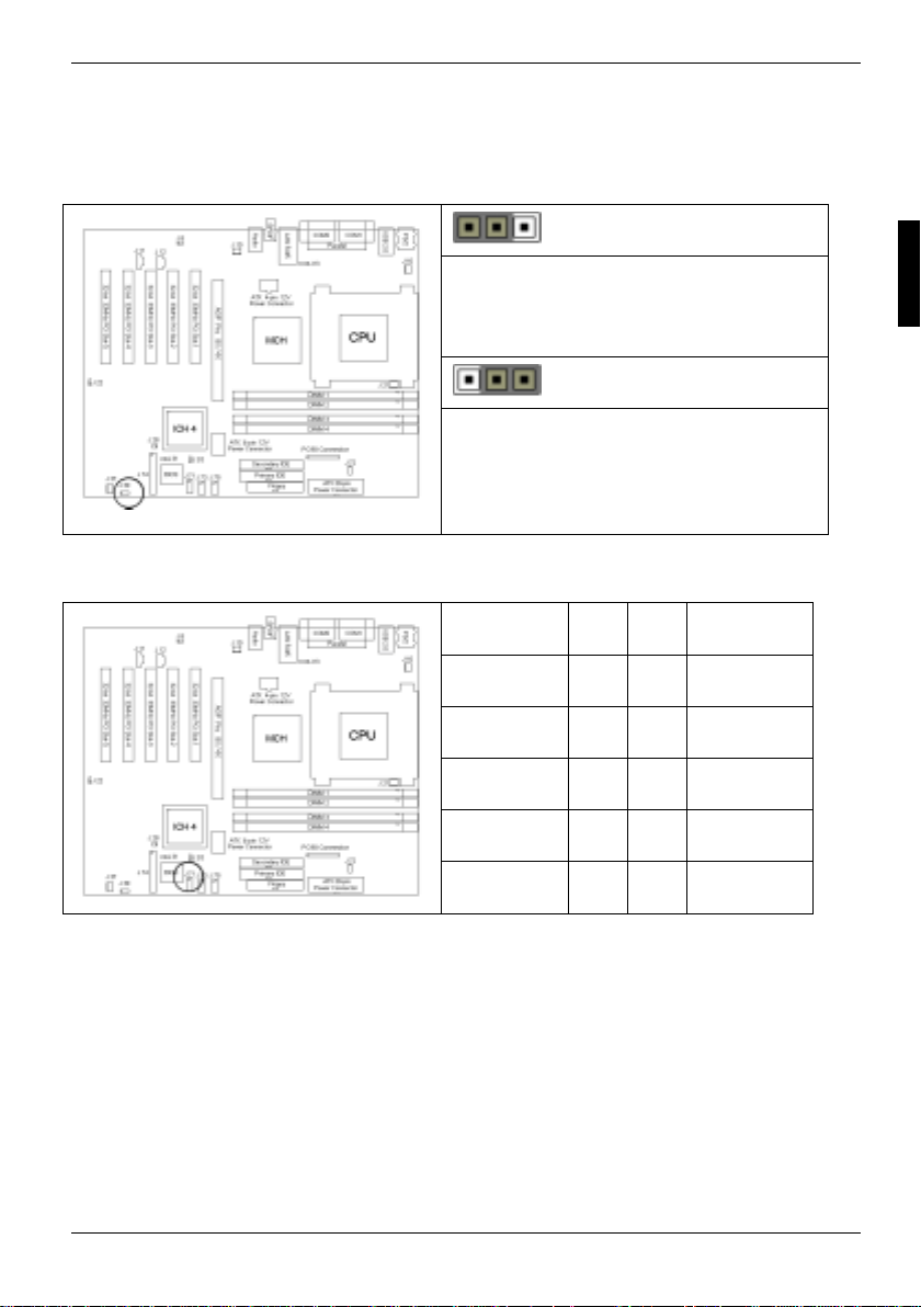
Enable/Disable On board LAN Jumper (J8)...............................................................................8
Fan Connectors (J10, J16, J21 and J37) ................................................................................... 8
AUX Audio connector (J11) and CD Audio connector (J12).......................................................9
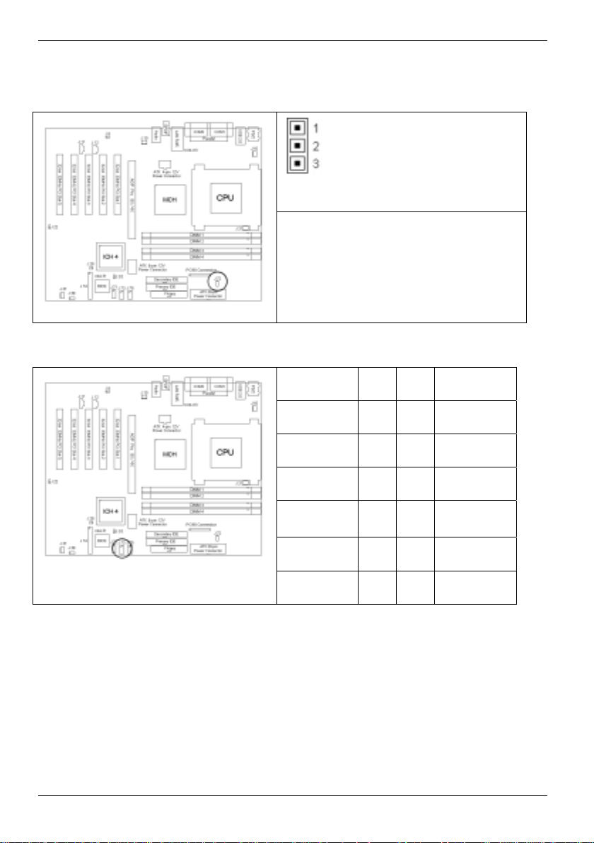
ACPI Wake-up Jumper for USB Port-A and Port-B (J13)...........................................................9
Clear CMOS Jumper (J28)...................................................................................................... 10
Recovery Jumper (J35)............................................................................................................10
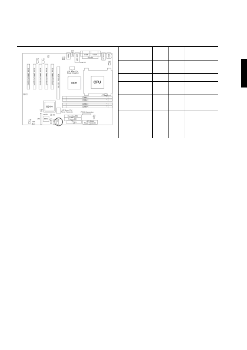
ACPI Wake-up Jumper for USB Port-C, Port-D, Port-E and Port-F (J39).................................11
Front Panel Audio Connector (J71)..........................................................................................11
Chassis Intrusion Connector (J72)...........................................................................................12
Front Panel USB Header (J73)................................................................................................12
Front Panel USB Header (J79)................................................................................................13
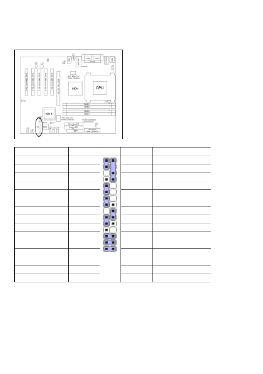
Front Panel Connector (J74)....................................................................................................14
Installing the Memory......................................................................................................................15
Memory Installation Procedure ................................................................................................16
Installing the Processor and Heatsink..............................................................................................17
Installing Add-In Cards....................................................................................................................19
Connecting External Devices...........................................................................................................20
Installing the Power Supply .............................................................................................................21
Attaching IDE and Floppy Drive Cables...........................................................................................22
Replacing lithium battery .................................................................................................................23
Glossary..........................................................................................................................................24
A26361-D1356-Z120-1-7619
Page 10

Page 11
Mainboard D1356
Your mainboard is available in dif ferent configuration levels . Depending on the configuration chosen,
some of the hardware components des cribed may not be available on your mai nboard.
Notational conventions
The meanings of the symbols and fonts used in this manual are as follows:
indicates informati on whi ch is important for your healt h or f or preventing physical
damage.
!
indicates additional inf orm ation which is required to use the system properly.
i
Ê Text which follows thi s symbol describes ac tivities that mus t be performed in the order shown.
Ë This symbol indicates that you must ent er a bl ank space (press the Space B ar) at this point.
Ú This symbol indicates that you must press the Enter key.
Text in this typeface indicates screen output s.
Text in this bold typeface indicates the entries you make via the keyboard.
Text in italics indicates commands or menu items.
"Quotation marks" indicate names of chapters or term s.
A26361-D1356-Z120-1-7619 English - 1
Page 12
Important notes
Important notes
With the mainboard installed y ou m ust open the system to access the mainboard. How to dismantle
and reassemble the system is described in the operating manual accompanying t he system.
Connecting cables for peripherals must be adequately shielded to avoid interference.
Observe the safety notes in the operating manual of your system.
!
Incorrect replacement of the lithium battery may l ead to a risk of explosion. It is therefore
essential to observe t he i nstructions in the "Replac i ng l i thium battery" secti on.
Components can become very hot during operation. Ensure you do not touch
components when making extensions to the mainboard. There is a danger of burns!
The shipped version of this board complies with the requirements of the EEC directive
89/336/EEC "Electromagnetic compatibility".
Compliance was tested in a t ypical PC configuration.
When installing the board, refer to the specif ic installation information in the manual for
the receiving device.
The warranty is invalidated if the system is damaged during the installation or
replacement of expansions. Information on which expansi ons you can use is available
i
from your sales outlet or the customer service centre.
Information about boards
To prevent damage to the mainboard, the c omponents and conductors on it, pl ease take great care
when you insert or remove boards. Take great care to ensure that extension boards are slotted in
straight, without damagi ng components or conductors on the m ai nboard, or any other components,
for example EMI spring c ontacts.
Remove the plug from the mains outlet so that system and mainboard are totally disconnected from
the mains voltage.
Be careful with the locking mechanisms (catches, centring pins etc .) when you replace the
mainboard or components on it, f or example memory modules or proces sors.
Never use sharp objects (s crewdrivers) for leverage.
Boards with electrost at i c sensitive devic es (ESD) are identifiable by the l abel shown.
When you handle boards fitted with E SDs, you must, under all circumstances,
observe the following:
• You must always di scharge static build up (e.g. by touching a grounded object)
before working.
• The equipment and tools you us e m ust be free of static c harges.
• Remove the power plug from the mai ns supply before inserting or removing
boards containing ESDs.
• Always hold boards wit h ESDs by their edges.
• Never touch pins or conductors on boards fitted with ESDs.
2 - English A26361-D1356-Z120-1-7619
Page 13

List of features
Processor
• mPGA478 ZIF soc ket
• Supports I ntel Pentium 4 processor
• Supports 400/ 533M Hz Front-Side Bus
• Supports Hy per-Threadi ng
• Onboard 3-phase switching VRM 9.0
Chipset
• Intel E7205 chipset
• MCH + ICH4 + FWH
• Winbond W83627HF super I/O chip
• Analog Device ADM1027 system monitor chip
Memory
• Four 184-pin 2.5-Vol t DDR DIMM sockets
• Supports dual channel memory
• Supports up t o 4GB unbuffered DDR memory
• Supports E CC/non-ECC DDR200/266 DIMM
Expansion Slots
• One AGP 8X/4X Pro50 slot
• Five 32-bit 33M Hz (5V) PCI slots
• Total of si x usable slots
List of features
Integrated I/O
• Six USB 2.0 and 1.1 compatible ports
(2 rear connectors and 4 internal headers f or chipcard reader, front panel and/or optional US B
cable)
• Supports one f l oppy drive with 3 mode
• Two 9-pin serial c onnectors
• One 25-pin ECP/EPP/SPP parallel connector
• PS/2 mouse and keyboard connectors
IDE
• ICH4 provides two PCI bus master channels for up to four Enhanced IDE devic es
• Supports f or UDM A 33/66/100 IDE drives and ATA P I compliant devices
A26361-D1356-Z120-1-7619 English - 3
Page 14

List of features
Power Management
• ACPI - Supports ACPI S1, S3, S4 and S5 modes
− S3 is enabled by default, it can be disabled via BIOS s etting in which case the suspend
mode will be S1 instead of S3.
• Wake-Up from S 1 (stand by)
− PCI_PME#, RI#
− PS/2 keyboard, PS/ 2 m ouse
− USB activity/connect/disconnect
− RTC
− External Modem Ring Indic ator (#RI)
− Power Button
• Wake-Up from S 3 (suspend to RAM)
− PCI_PME#
− PS/2 keyboard, PS/ 2 m ouse
− USB activity/connect/disconnect (optional)
− RTC
− Power Button
− External Modem Ring Indic ator (#RI)
• Power-On from S4 (save to disk) and S5
− RTC
− Power Button
− USB activity/connect/disconnect
− PS/2 keyboard, PS/ 2 m ouse
− PCI_PME#
− External Modem Ring Indic ator (#RI)
Integrated LAN
• Intel 82540EM Gi gabi t Ethernet 10/100/1000Mbit
• PME wakeup support
Integrated Audio
• Intel ICH4 AC’97 compliant audio link
• ADI 1981A CODEC
• Line-in, , Mic-in rear jacks, Headphone out
• SPDIF di gi t a l out put with rear RCA connector
• Front panel audio header
• One 4-pin CD-ROM audio input header
• One 4-pin Auxiliary audio header
System Management
• Analog Device ADM1027 at I
2
C serial bus
• Total four 3-pin f an headers
• All fan headers with tachometer monitoring
• One 3-pin chass i s intrusion header
• Temperature, vol tage and fan monitoring
General Power Management
• CPI 2.0b c om p l i ant
• PCI Bus P ower M anagement 1.1 compliant
• Memorize power-state before AC power cut & rest ore upon boot
4 - English A26361-D1356-Z120-1-7619
Page 15

BIOS
• Phoenix BI OS 4.06 on 4 Mbit Flash ROM
• Supports Hy per-Threadi ng technology
• Supports BIOS Boot Specif ic at ion v1.1 (BBS)
• Supports A CP I 2.0 S1, S3, S4 and S5
• Supports SMBIOS v2.3
• Auto conf i guration of IDE hard disk types
Form Factor
• Standard ATX footprint (12” x 9.6”)
• Six-layer design
• ATX12V (20pin+4pi n+6pin) power connectors
• Stacked parallel (one), serial (two) connectors
• Stacked USB (two) connectors
• Stacked PS/2 keyboard and mouse connectors
• Stack ed audi o Li ne-i n, Headphone out, and Mic-in jacks (Amplifier integerated)
• One SPDIF RCA connector (output)
• One RJ-45 10/100/1000 LA N connector with LEDs
Regulatory
• FCC Class B (Declaration of Conformity)
• European Communit y CE (Declaration of Conformit y)
List of features
A26361-D1356-Z120-1-7619 English - 5
Page 16
List of features
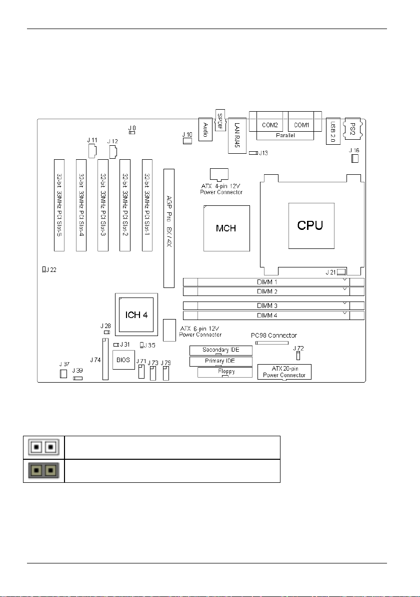
Overview Board, Jumpers and Connectors
This diagram is representative of the latest board revisi on available at the time of publishing. The
board you receive may not look exactly like the above di agram .
Jumper Legend
Jumper OFF without jumper cover
Jumper ON with jumper cover
6 - English A26361-D1356-Z120-1-7619
Page 17
Jumper and Connector Settings
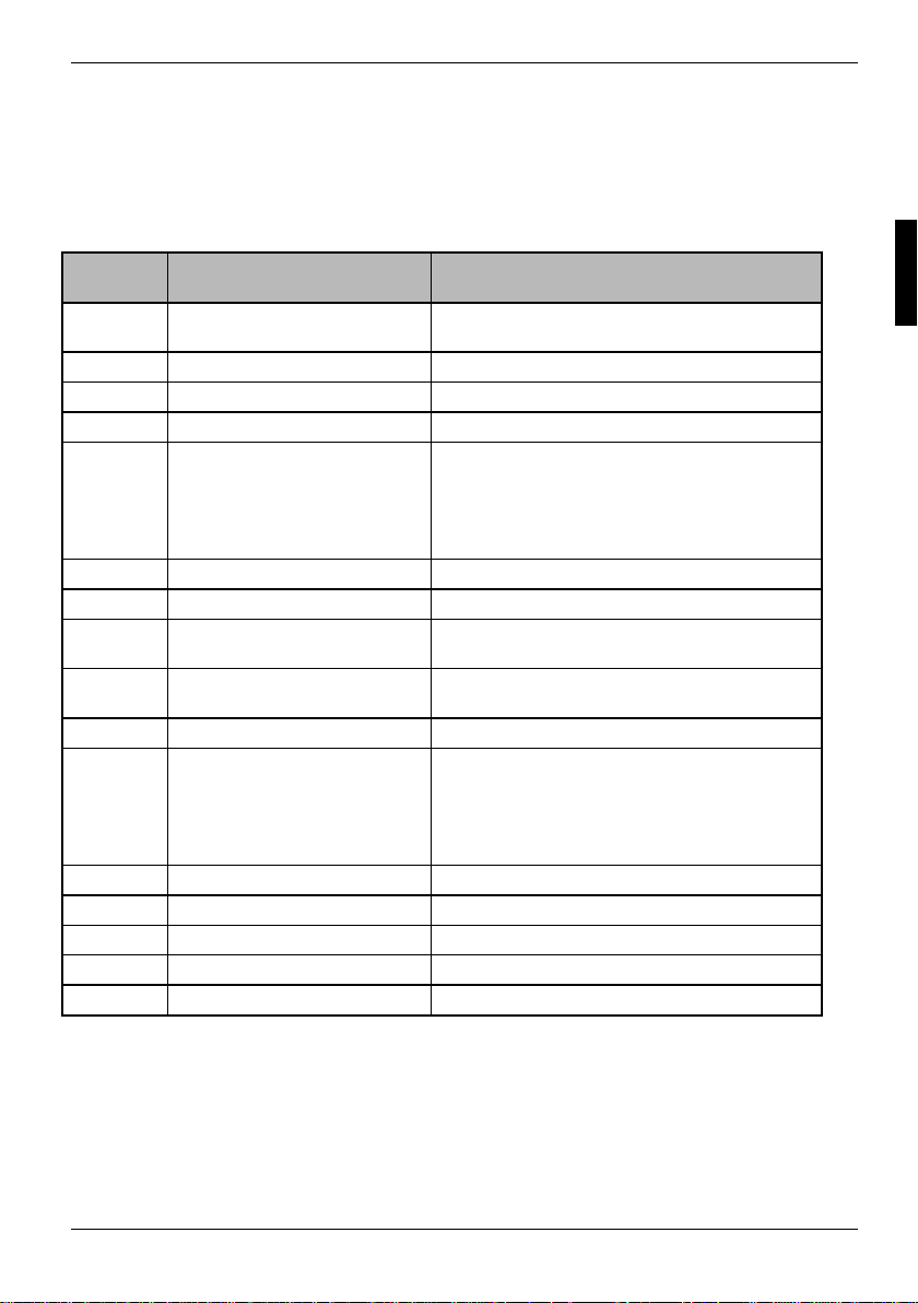
Overview
Jumper and Connector Settings
Jumper /
Connector
J8 Enable/Disable Onboard Intel
J10 Fan Connector Wit h t a chometer monitoring
J11 AUX Audio Connector
J12 CD Audio Input Connector
J13
J16 Fan Connector Wit h t a chometer monitoring
J21 Fan Connector Wit h t a chometer monitoring
J28 Clear CMOS Jumper Open: Normal (Default)
J35 Recovery Open: Normal (Default)
J37 Fan Connector Wit h t a chometer monitoring
J39
J71 Front Panel Audio Connector
J72 Chassis Intrusion Connec tor
J73 Front Panel USB Header-1
J74 Front Panel Connector
J79 Front Panel USB Header-2
Function Settings
82540EM GbE NIC
ACPI Wake-up Jumper
(USB Port-A and USB Port -B)
ACPI Wake-up Jumper
(USB Port-C, USB Port-D,
USB Port-E and USB Port-F)
Open: Enable (Default)
Close: Disable
Close Pin-1 and Pin-2
Rear panel USB devices’ ACP I S1 wake up
Close Pin-2 and Pin-3 (Default)
Rear panel USB devices’ ACP I S1/S3/S4 wake
up
Close: Clear CMOS Mode
Close Pin-1 and Pin-2: Recovery mode
Close Pin-1 and Pin-2
Front panel USB devices’ A CP I S1 wake up
Close Pin-2 and Pin-3 (Default)
Front panel USB devices’ A CP I S1/S3/S4
wake up
A26361-D1356-Z120-1-7619 English - 7
Page 18
Jumper and Connector Settings
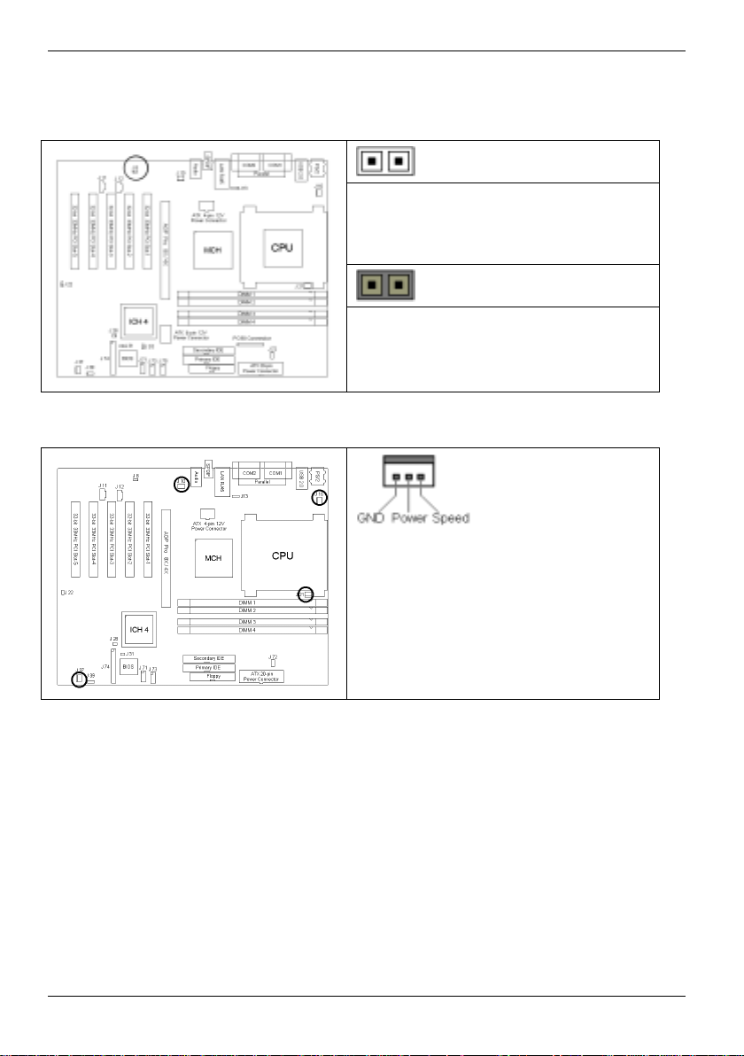
Enable/Disable On board LAN Jumper (J8)
OPEN (Default) - To enable onboard LAN
CLOSE - To disable onboard LAN
Fan Connectors (J10, J16, J21 and J37)
Use these headers to connect chassis and
processor cooling fans to your motherboard.
Cooling fans can keep the system stable and
reliable for its product li fe.
Max 850mA fans supported
8 - English A26361-D1356-Z120-1-7619
Page 19
Jumper and Connector Settings
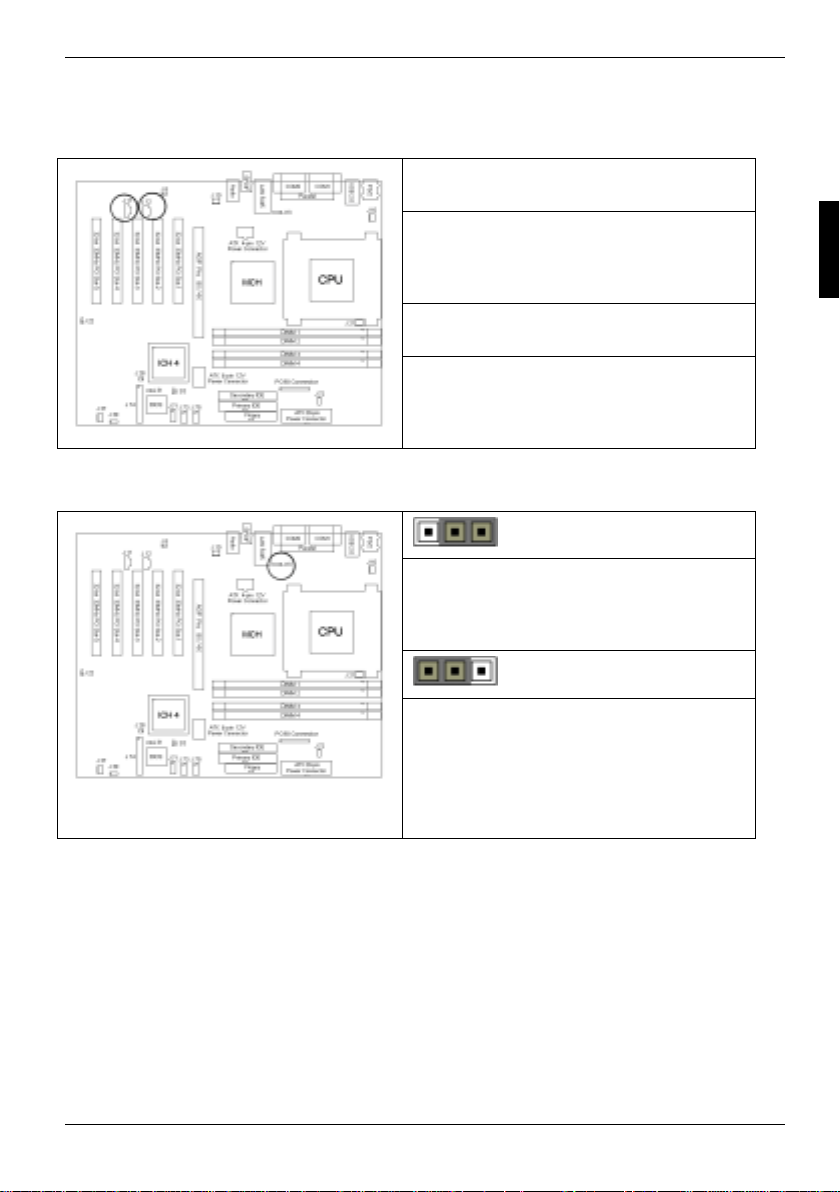
AUX Audio connector (J11) and CD Audio connector (J12)
J11 (AUX Audio connector)
Connects to internal audio sources such as
TV tuner, MPEG, or other si m i l ar cards
J12 (CD Audio connector)
Connects to a CD-ROM drive vi a an opt i onal
CD audio cable
ACPI Wake-up Jumper for USB Port-A and Port-B (J13)
pin-1
CLOSE Pins 1 and 2
Rear panel USB devices’ ACP I S1 wake up
pin-1
CLOSE Pins 2 and 3 (Default)
Rear panel USB devices’ ACP I S1/S3/S4
wake up
total current of all USB devices should not exceed the
standby current rating of the power supply
A26361-D1356-Z120-1-7619 English - 9
Page 20
Jumper and Connector Settings
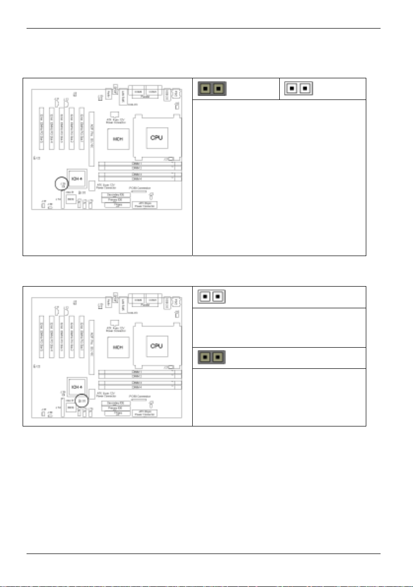
Clear CMOS Jumper (J28)
Recovery Jumper (J35)
Clear Default
You can reset the CMOS set tings by using
this jumper when you
• Have forgotten your system/setup
password
• Need to clear system BIOS setting
Ê Power off system and disconnect power
supply from AC source
Ê Use jumper to close JP 28 for several
seconds to Clear CMOS
Ê Take off jumper from JP28 (def aul t
setting)
Ê Reconnect power supply to AC source
Ê Power on system
Use “F2” key to go into system BIOS setup
OPEN (Default)
CLOSE Pins 1 and 2
Recovery mode
10 - English A26361-D1356-Z120-1-7619
Page 21
Jumper and Connector Settings
ACPI Wake-up Jumper for USB Port-C, Port-D, Port-E and Port-F (J39)
pin-3
CLOSE Pins 1 and 2
Front panel USB devices’ A CP I S1 wake up
pin-3
CLOSE Pins 2 and 3 (Default)
Front panel USB devices’ A CP I S1/S3/S4
wake up
Total current of all USB devices should not exceed the
standby current rating of the power supply
Front Panel Audio Connector (J71)
Signal
Description
MIC input 12Analog GND
MIC power 34Analog VCC
Right line
output
NC 78 Key
Left line
output
Note: If Audio Front panel is not bei ng used, put jumper on pins 5-6, and 9-10.
A26361-D1356-Z120-1-7619 English - 11
Pin#Pin
#
56
910
Signal
Description
Right line
return
Left line
return
Page 22
Jumper and Connector Settings
Chassis Intrusion Connector (J72)
Pin-1
Intrusion cable detect i on (l ow asserted)
Pin-2
Intrusion detection (low asserted)
Pin-3
GND
Front Panel USB Header (J73)
Signal
Description
Key 1 2
VCC 3 4 VCC
Data
negative A
Data
positive A
GND 9 10 GND
Key 11 12
Pin#Pin
#
Chipcardrea
56
78
Signal
Description
der on
Data
negative B
Data
positive B
Not
connected
12 - English A26361-D1356-Z120-1-7619
Page 23
Front Panel USB Header (J79)
Jumper and Connector Settings
Signal
Description
Key 1 2
VCC 3 4 VCC
Data
negative A
Data
positive A
GND 9 10 GND
Key 11 12
Pin#Pin
#
56
78
Signal
Description
Chipcard-
reader On
Data
negative B
Data
positive B
Not
connected
A26361-D1356-Z120-1-7619 English - 13
Page 24
Jumper and Connector Settings
Front Panel Connector (J74)
Signal Description Pin # Pin # Signal Description
Sleep LED “— “ 12Speaker “— “
Sleep LED “+ “ 34Key
Key 56GND
Power LED “+ “ 78Speaker “+ “
Power LED “+ “ 910Key
GND 11 12 Key
Message LED “+ “ 13 14 Key
Message LED “— “ 15 16 Not connected
Key 17 18 SCSI LED Input
HD LED “+ “ 19 20 SCSI LED Input
HD LED “— “ 21 22 Not connected
GND 23 24 Key
Power Button 25 26 GND
Sleep Button 27 28 GND
Reset Button 29 30 GND
14 - English A26361-D1356-Z120-1-7619
Page 25
Installing the Memory
Installing the Memory
Before attempting to ins tall any memory, make sure that the memory you have is compatible with
the motherboard as well as the processor. For example, DDR200 and DDR266 memory m odules
can be used for FSB=400MHz Intel Pentium 4 processor but only DDR266 memory modules
can be used for FSB=533MHz Intel Pentium 4 processor.
A current list of the m emory modules recommended for this mainboard is available on the Internet
at: www.fujitsu-siemens.de/mainboards.
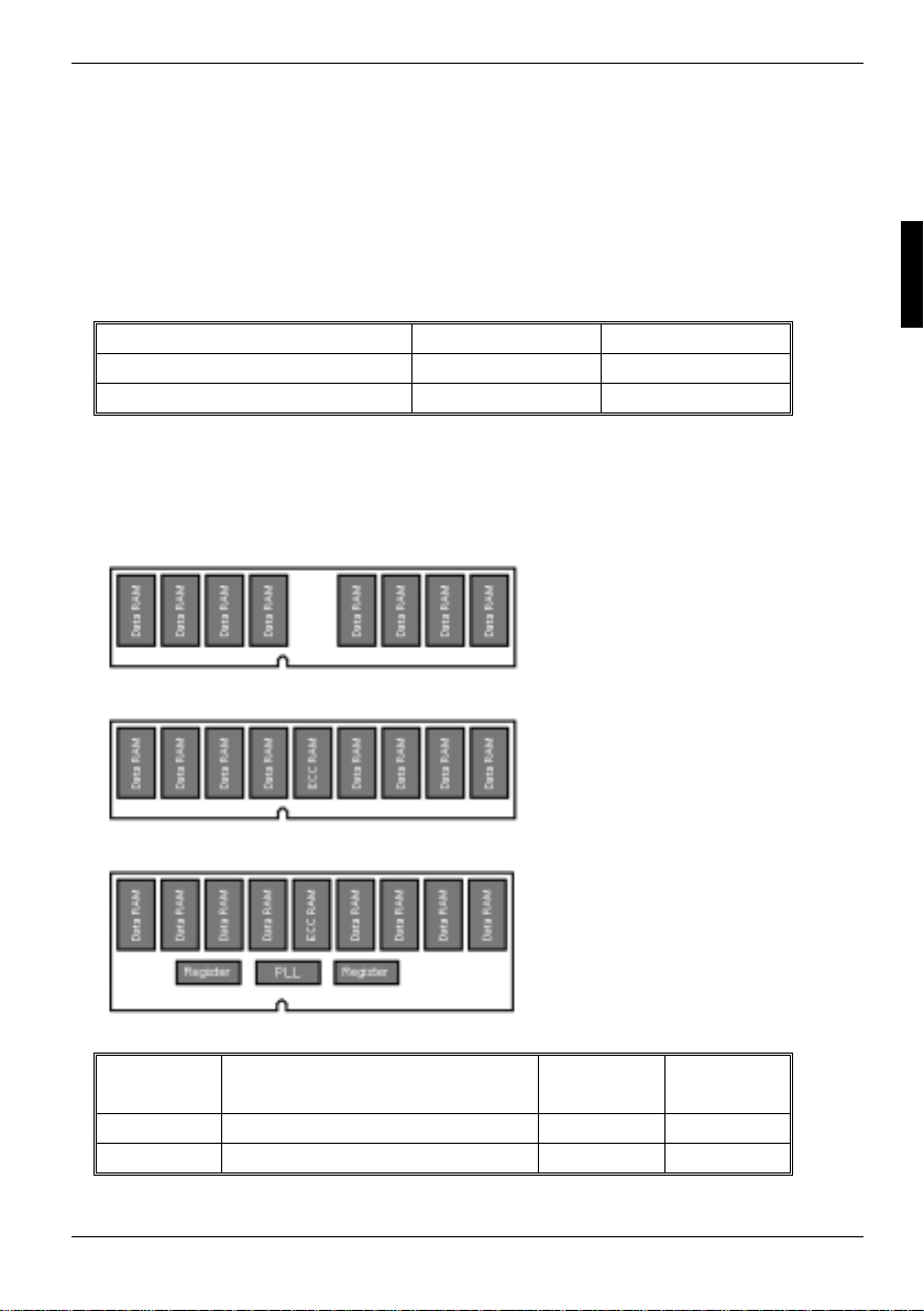
DDR200 (PC1600) DDR266 (PC2100)
Pentium 4 mPGA478 FSB=400MHz Y es Yes
Pentium 4 mPGA478 FSB=533MHz No Yes
Here are a few key points to note before installing memory modules onto your board.
• All installed memory will be aut omatically detected - no need to set any jumpers
• Supports 128MB, 256MB, 512MB and 1GB unbuffered DDR200/ 266 m odul es
• Supports up t o 4GB of memory
DDR Unbuffered Non-ECC
supported
DDR Unbuffered ECC
supported
DDR Registered ECC
unsupported
Memory
Slot
Two pieces DIMM1+DIMM2 or DIMM3+DIM M4 Dual 128-bit
Four pieces DIMM1+DIMM2+DIMM3+DIM M 4 Dual 128-bit
A26361-D1356-Z120-1-7619 English - 15
Memory
Channel
Memory
Bandwidth
Page 26
Installing the Memory
Dual Memory Channel
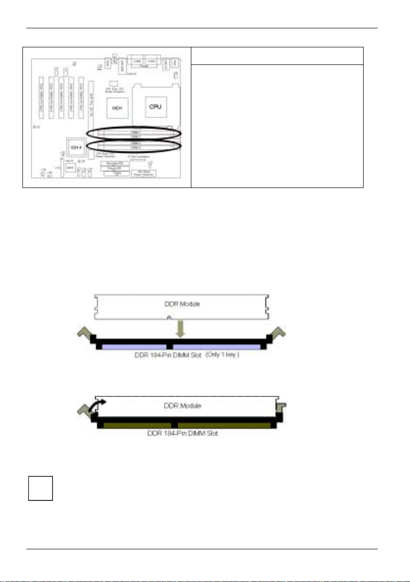
At least two unbuffered DDR E CC/non-ECC
modules must be instal l ed
Memory modules must be i nstalled in pairs
DIMM1+DIMM2 or
DIMM3+DIMM4 or
DIMM1+DIMM2+DIMM3+DIMM4
Dual channel 128-bit memory bandwidth
Note: The pair of memory module in slots DIMM1 and DIMM2 must be identical to the pair in slots
DIMM3 and DIMM4.
Memory Installation Procedure
When installing memory modules, make sure the modules align properly with the memory socket.
There should be a key (small indent ) on your memory module that fits according to the key in the
memory socket. DDR m odul es and sockets have only one key, which is slightly off-center of the
module/socket. The method of installing memory modules is detailed in the following diagrams.
Once the memory modules are firmly seated in the socket, two clamps on eit her s i de will close and
secure the module into the socket. Sometimes you may need to close the clam ps manually.
To remove the memory module, s i m pl y push the clamps outwards unt i l the memory module pops
up. Then remove the module.
When installing memory, a module may require a considerable amount of force to seat
properly, although this is very rare. To avoid bending and damaging your motherboard,
i
place it on its anti-s tatic bag and onto a flat surface, then proceed with memory
installation.
16 - English A26361-D1356-Z120-1-7619
Page 27
Installing the Processor and Heatsink
YOU MUST unplug the power supply before performing system hardware changes in
order to avoid damaging the board or expansion device..
!
Installing the Processor and Heatsink
The S2662 supports the mPGA478 Pentium 4 processors technologi es from Intel. A current li st of
the processors supported by this mainboard is available on t he Internet at: www.fujitsu-
siemens.de/mainboards.
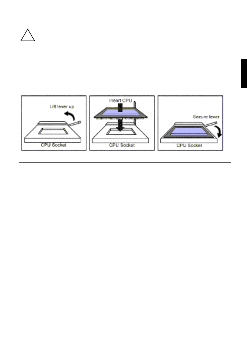
The following diagrams will detail how to install your processor:
The processors you choose to use may not look exactly lik e t he one pictured above, nor will the
socket look exactly the same. The diagram is a visual guide to help you instal l processors.
Lift the lever on the socket as far back as possible to the socket.
Ê Align the processor with the socket. There are keys underneath the processor just like on
memory modules to ensure that they insert the correct way.
Ê Seat the processor firm l y into the socket by gently pressing down until the proc essor sits flush
with the socket.
Ê Place the socket l ever back down until it snaps i nto place.
Your processor is inst al l ed.
Take care when installing the processor as it has fragile connector pins that c an bend and break if
inserted improperly.
Heatsink Installation
After you are done installing the proces sor, you should proceed to installing the heatsink. The
heatsink will ensure that the processor does not overheat, and will continue t o operate at maximum
performance. An overheated process or is also dangerous to the long-term reliability of the
motherboard.
The following diagram will illustrate how to install the most c ommon heat s i nks:
A26361-D1356-Z120-1-7619 English - 17
Page 28
Installing the Processor and Heatsink
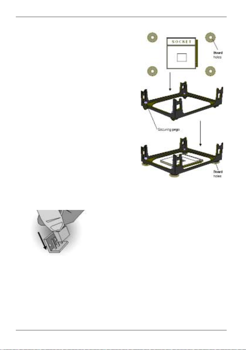
Install the mounting brac ket onto the motherboard by
aligning the bracket with t he four holes around the
processor socket. Once the bracket is aligned, press
down on the four white pegs on the bracket until they
insert securely, l ocking the bracket onto the
motherboard. Then proceed to installing the heatsi nk.
Instructions on how to i nstall heatsinks shoul d be
provided with the heatsink i tself.
First, use thermal com pound (al so called heatsink
compound or thermal grease) and apply a sm al l am ount
on to the processor’s core – the small shiny square in
the center of the process or.
Then, at an angle, clip one side of the heatsink onto the
socket and then lay the heatsink flat onto the processor.
Then clip the other end of the heatsi nk down by using a
flathead screwdriver.
Some heatsinks have a s m al l clip on the inside of one of
the clips which you c an i nsert a small flathead sc rew
driver into to secure the heat sink.
Because one side of the socket is raised (and usually
has “SOCKET” imprinted int o i t) heatsinks have an
indent on one side to secure flush with the raised side of
the socket.
Be sure to carefully obs erve which side your heatsink i s
seated before securing it down t o avoid damaging the
processor, the heatsink or both.
Finishing Installing the Heatsink
After you finish installing the heatsink ont o t he processor and socket, at tach the end wire of the fan
(which should already be attached to the heatsink) to the mot herboard. The following diagram
illustrates how to connect f ans onto the motherboard.
After you have finished inst alling all the fans you can connect your drives (hard drives, CD-ROM
drives, etc.) to your motherboard.
18 - English A26361-D1356-Z120-1-7619
Page 29
Installing Add-In Cards
Installing Add-In Cards
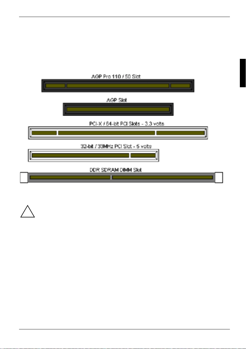
Before installing add-in cards, it is helpful to k now i f they are fully compati bl e wi th your motherboard.
For this reason, we have provided t he di agram s below showing the most comm on slots that may
appear on your motherboard. Not all of the slots shown will necessarily appear on your
motherboard. However, there will be combinations of what you see here.
Find the appropriate slot for your add-i n card and insert the card firmly . Do not force any add-in
cards (or anything else) into any slots if they will not seat in place.
YOU MUST unplug the power supply before performing system hardware changes in
order to avoid damaging the board or expansion device.
!
Before Continuing onto secti on Connecti ng E xternal Devices, make sure everythi ng i s properly
connected. Things like j um pers and case wiring are the most c om m on causes of troubleshooting
frustrations, both f or t he end-user and for any company doing techni cal support.
A26361-D1356-Z120-1-7619 English - 19
Page 30
Connecting External Devices
Connecting External Devices
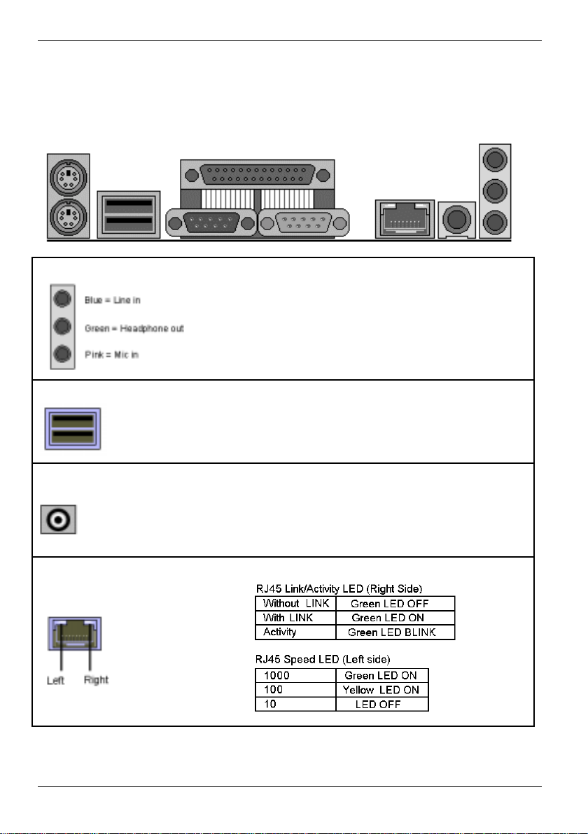
The following diagrams will detail the rear port stack f or this S2662 motherboard:
Audio Port
Line In Jack - Connects t o external devices for
playback or recording
Headphone Out Jack - Connects t o headphone or
speakers (Amplifier i ntegrated)
Microphone In Jack - Connects to an external
microphone
USB 2.0/1.1
USB 2.0 /1.1
Two rear USB 2.0/1.1 connectors
Four front USB 2.0/1.1 headers (J 73)
SPDIF
SPDIF RCA connector
Sony/Philips Digital Interface (SPDIF) is the newest
audio transfer file format . It provides impressive sound
quality through this RCA connector and allows you to
enjoy digital audio instead of anal og audi o.
RJ45 LAN Port
20 - English A26361-D1356-Z120-1-7619
Page 31
Installing the Power Supply
Installing the Power Supply
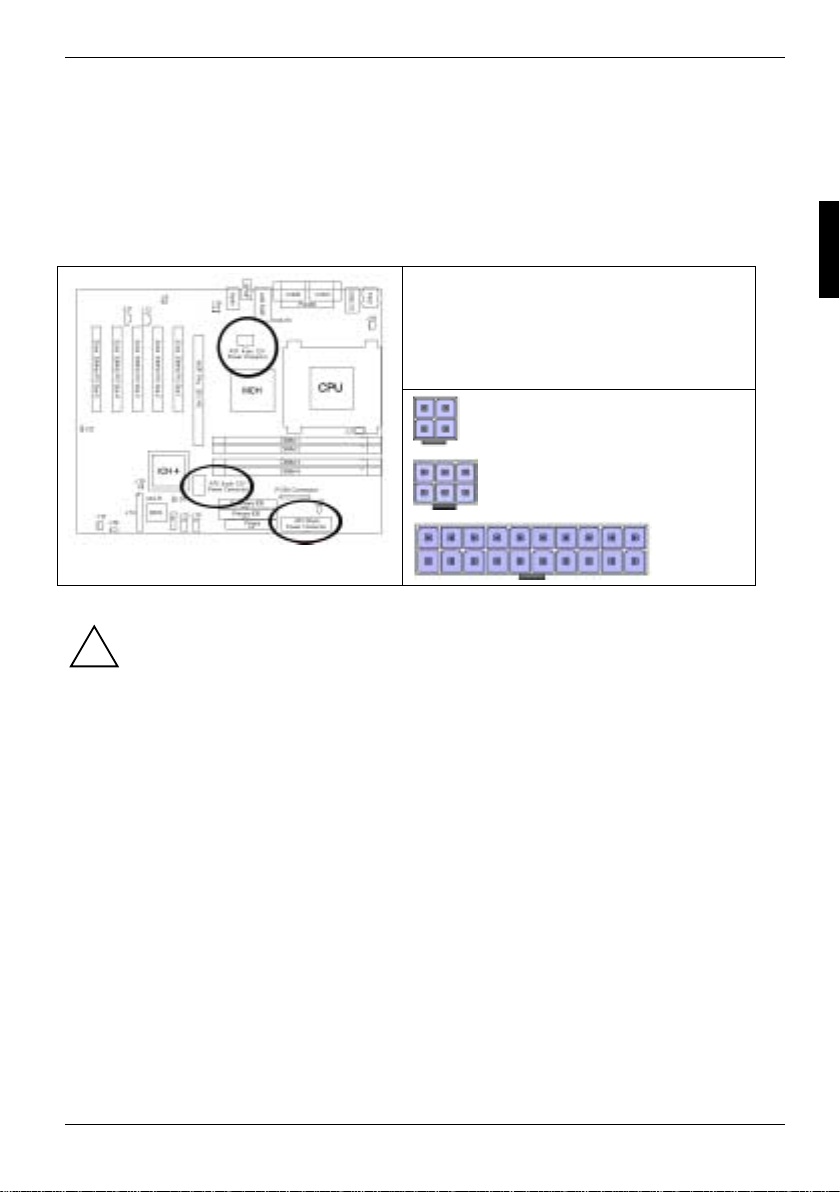
This motherboard requires that you have an ATX12V power supply. The st andard ATX12V power
supply has two power connectors, a 20-pin ATX connector and an addit i onal 4-pi n square
connector. The CPU power is provi ded by the onboard voltage switching regul ator which is sourced
from the 4-pin square connector. The CP U won't be powered without connecting the 4-pi n square
connector.
ATX 12V
(4-pin) connector + (6-pin) connector +
(20-pin) connector
YOU MUST unplug the power supply before pl uggi ng the 20-pin and 4-pin cables to
motherboard connectors.
!
A26361-D1356-Z120-1-7619 English - 21
Page 32
Attaching IDE and Floppy Drive Cables
Attaching IDE and Floppy Drive Cables
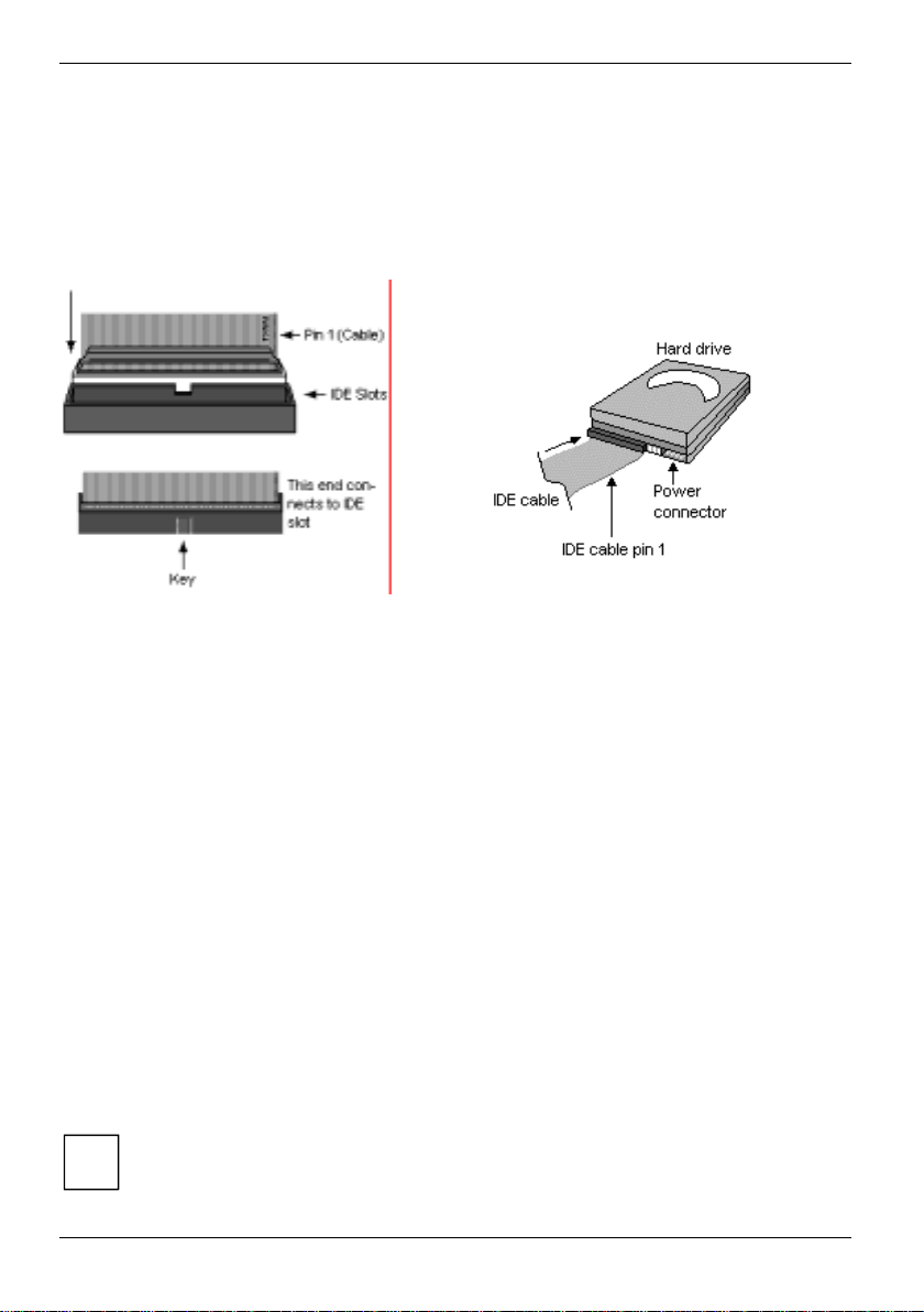
Attaching IDE drive cabling is simple. These cables are “keyed” to only allow t hem to be connected
in the correct manner. Tyan motherboards have two on-board IDE channels, each supporting two
drives. The grey connector designates the Primary channel , whi l e the black connector designat es
the Secondary channel. Attaching IDE cables to the IDE connectors is illustrated below:
Simply plug in the BLUE E ND of the IDE cable into the mot herboard I DE connector, and the other
end(s) into the drive(s). Ea ch standard IDE cable has three c onnectors, two of which are closer
together. The BLUE connector t hat is furthest away from t he other two is the end that connect s to
the motherboard. The other two connect ors are used to connect to drives .
Attaching a floppy drive can be done in a similar manner to an IDE dri ve. Most of the current floppy
drives on the market require that the cable be installed with the colored stripe (pin-1) positi oned next
to the power connector. In most cases, there will be a key pin on the cable whic h will f orce proper
connection of the cable.
Below are some symptoms of incorrectly ins talled floppy drives:
• Drive is not automatically detec ted
− Check if the floppy c ontroller is enabled under the BIOS set tings
− Verify that the floppy cable is installed co rrectly
− Verify that the floppy drive is working properly (i. e. try a new drive)
• Drive Fail message at bootup
− Verify with another drive or cable
• Drive does not power on
− Check power cable and cabling
− Check power supply
• Drive act i vity light is cons tantly on
− Cable is on backwards
Pin 1 on the cable (usually des i gnated by a colored wire) faces the dri ve’s power
connector.
i
22 - English A26361-D1356-Z120-1-7619
Page 33
Replacing lithium battery
Replacing lithium battery
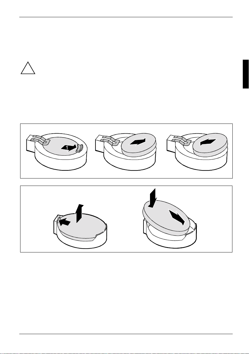
In order to permanently save t he system information, a lithium battery is installed to provide the
CMOS-memory with a current. A corresponding error message notifi e s the user when the charge is
too low or the battery is empty. The lithium battery must then be replaced.
Incorrect replacement of the lithium battery may l ead to a risk of explosion!
!
The lithium battery may be repl aced only with an identical battery or with a type
recommended by the manufactu rer.
Do not throw lithium batteries into the household waste. They m ust be disposed of in
accordance with local regulations concerning special waste.
Ensure that you insert t he battery the right way round. The plus pole must be on the top!
The lithium battery holder exi sts in different designs that function in the same way.
2
3
2
1
3
3
Ê Press the locking lug i n the direction of the arrow; the battery jumps somewhat out of the
holder (1).
Ê Remove the battery (2).
Ê Insert a new lithium batt ery of the same type into t he socket (3).
A26361-D1356-Z120-1-7619 English - 23
Page 34
Glossary
Glossary
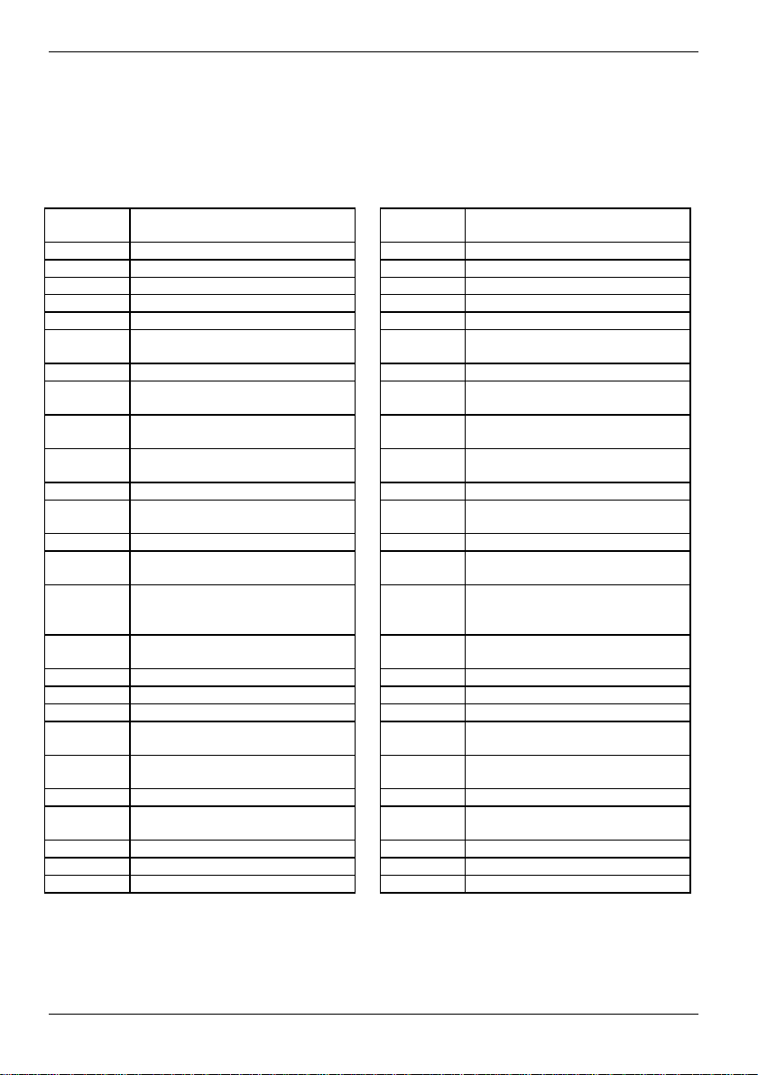
The technical terms and abbrevi ations given below represent only a s el ection of the full list of
common technical term s and abbreviations.
Not all technical terms and abbreviations listed here are valid for the described mainboard.
ACPI Advanced Configuration and
Power Management Interface
AC'97 Audio Codec '97 LAN Local Area Network
AGP Accelerated Graphics Port LSA LAN Desk Service Agent
AMR Audio Modem Riser MCH Memory Controller Hub
AOL Alert On LAN MMX MultiMedia eXtension
APM Advanced Power Management P64H P CI64 Hub
ATA Advanced Technology
Attachment
BIOS Basic Input Output System PXE Preboot eXecution Environment
BMC Baseboard management
controller
CAN Controller Area Network RAMDAC Random Access Memory Digital
CPU Central Processing Unit RDRAM Ram bus Dynamic Random
CNR Communication Network Riser RIMM Rambus Inline Memory Module
C-RIMM Continuity Rambus Inline
Memory Module
DIMM Dual Inline Memory Module SB Soundblaster
ECC Error Correct i ng Code SDRAM Synchronous Dy nam i c Random
EEPROM Electrical Erasable
Programmable Read Only
Memory
FDC Floppy disk controller SIMD Streaming Mode Instruction
FIFO First-In First-Out SMBus System Management Bus
FSB F ront Side Bus SVGA Super Video Graphic Adapter
FWH Firmware Hub US B Universal S eri al Bus
GMCH Graphics and Memory Controll er
Hub
GPA Graphics Performance
Accelerator
I2C Inter Integrated Circuit
IAPC Instantly Available Power
Managed Desktop PC Design
ICH I/O Controller Hub
IDE Intelligent Drive Electronics
IPSEC Internet Protocol Security
ISA Industrial Standard Architecture
PCI Peripheral Component
Interconnect
RAM Random Access Memory
Analogue Converter
Access Memory
RTC Real Time Clock
Access Memory
SGRAM Synchronous Graphic Random
Access Memory
(Single Instruction Multiple Data)
VGA Video Graphic A dapter
WOL Wake On LAN
24 - English A26361-D1356-Z120-1-7619
Page 35

Glossary
A26361-D1356-Z120-1-7619 English - 25
 Loading...