

Page 1
COMPONENT
.com Technisches Handbuch / Technical Manual
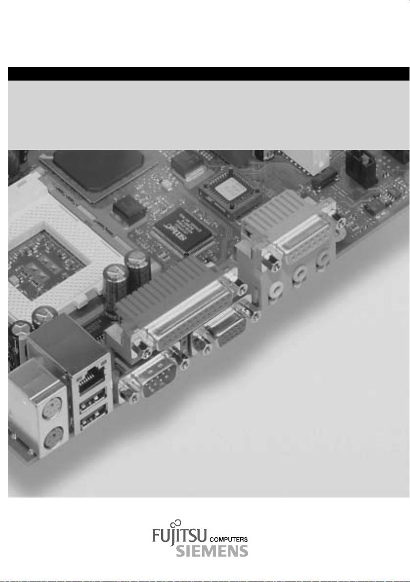
Systembaugruppe / System Board D1332
Page 2

Are there ...
... any technical problems or other questions which you would like to be clarified?
Please contact:
· your sales partner
· your sales outlet
Further information can be found in the "Safety, Warranty and Ergonomi cs" booklet.
The latest information on our produc t s, tips, updates, etc., can be found on the internet under:
http://www.fujitsu-siemens.com
Are there ...
... any technical problem or other question you need clarified?
Please contact:
· your sales partner
· your sales outlet
You will find further information in the manual "Safety, Warranty and Ergonomics".
The latest information on our produc t s, tips, updates, etc., can be found on the Internet under:
http://www.fujitsu-siemens.com
Page 3

Page 4
Dieses Handbuch wurde auf Recycling-Papier gedruckt.
This manual has been printed on recycled paper.
Ce manuel est imprimé sur du papier recyclé.
Este manual ha sido impreso sobre papel reciclado.
Questo manuale è stato stampato su carta da riciclaggio.
Denna handbok är tryckt på recyclingpapper.
Dit handboek werd op recycling-papier gedrukt.
Herausgegeben von/Published by
Fujitsu Siemens Computers GmbH
Bestell-Nr./Order No.:
Printed in the Federal Republic of Germany
AG 0102 01/02
A26361-D1332-Z120-1-7419
A26361-D1332-Z120-1-7419
Page 5
Systembaugruppe
D1332
System Board D1332
Technisches Handbuch
Technical Manual
German
English
Ausgabe Januar 2002
January 2002 edition
Page 6

Pentium and Celeron are registered trademarks of Intel Corporation, USA.
Microsoft, MS, MS-DOS and Windows are registered trademarks of Microsoft Corporation.
PS/2 and OS/2 Warp are registered tradem arks of International Busi ness Machines, Inc.
All other trademarks referenced are trademarks or registered trademarks of their respective
owners, whose protected rights are acknowledged.
Copyright ã Fujitsu Siem ens Computers GmbH 2002
All rights, includi ng ri ghts of translation, reproduc t i on by printing, copying or sim i l ar methods,
in part or in whole, are reserved.
Offenders will be liable for damages.
All rights, including rights creat ed by patent grant or registration of a utilit y model or design,
are reserved.
Delivery subject to availability. Right of technical modification reserved.
This manual was produced by
cognitas. Gesellschaft für Technik-Dokument at i on mbH
www.cognitas.de
Intel, Pentium and Celeron are registered trademarks of Intel Corporat i on, USA.
Microsoft, MS, MS-DOS and Windows are registered trademarks of Microsoft Corporation.
PS/2 and OS/2 Warp are registered tradem arks of International Busi ness Machines, Inc.
All other trademarks referenced are trademarks or registered trademarks of their respective
owners, whose protected rights are acknowledged.
All rights, includi ng ri ghts of translation, reproduc t i on by printing, copying or sim i l ar methods,
even of parts are reserved.
Offenders will be liable for damages.
All rights, including rights creat ed by patent grant or registration of a utilit y model or design,
are reserved. Delivery subject to availability.
Right of technical modi f i cation reserved.
This manual was produced by
cognitas. Gesellschaft für Technik-Dokument at i on mbH
www.cognitas.de
Page 7

Contents
Introduction........................................................................................................................................1
Notational conventions ..............................................................................................................1
Important notes..................................................................................................................................1
Information about boards...........................................................................................................2
Features............................................................................................................................................3
External ports............................................................................................................................4
Internal ports and connectors ....................................................................................................5
Temperature / System monitoring..............................................................................................6
Hard disk connection.................................................................................................................7
PCI bus interrupts......................................................................................................................7
Settings with switches and jumpers...................................................................................................8
Recovering System BIOS - switch 2.......................................................................................... 8
Defining auxiliary voltage - Switch 4 ..........................................................................................8
Add-on modules ................................................................................................................................9
Installing and removing processors..........................................................................................10
Upgrading main memory..........................................................................................................11
Installing network board with WOL...........................................................................................12
Replacing the lithium battery....................................................................................................13
Glossary..........................................................................................................................................14
A26361-D1332-Z120-1-7419
Page 8

Page 9
Introduction
Depending on the configuration chosen, some of the hardware components desc ri bed
may not be available on your system board.
i
You will find further information in the "BIOS Setup" description.
Further information on drivers is provided in the readme files on hard disk or on the supplied driver
diskettes or on the "Drivers & Utility" CD.
Notational conventions
The meanings of the symbols and fonts used in this manual are as follows:
indicates informati on whi ch is important for your healt h or for preventing physical
damage.
!
indicates additional inf orm ation which is required to use the system properly.
i
Ê Text which follows thi s symbol describes ac t i vities that must be performed in the order shown.
Text in this typeface indicates screen outputs.
Text in this bold typeface indicates the entries you make via the keyboard.
Text in italics indicates commands or menu it ems.
"Quotation marks" indicate names of chapters or term s.
Important notes
Store this manual clos e t o the system board. If you pass the system board on to third parti es, you
should pass this manual on wi th it.
You cannot access the system board components without first opening the system. How to
dismantle and reassemble t he system is described in the Operating Manual accompanying the
system.
Please observe the safet y information provided in the "I m portant notes" chapter in the
system’s operating manual.
!
Incorrect replacement of the lithium battery may l ead t o a ri sk of explosion. It i s therefore
essential to observe the instructions in the "Add-on modules" -
"Replacing the lithium battery" section.
Components can become very hot duri ng operation. Ensure you do not touch
components when making extensions to the system board. There is a danger of burns!
A26361-D1332-Z120-1-7419 English - 1
Page 10
Important notes
The shipped version of this board complies with the requirements of the EEC
directive 89/336/EEC "Electromagnetic compatibility".
Compliance was tested in a t ypical PC configuration.
When installing the board, refer to the specific installation information in the
Operating Manual or Technical Manual for the receiving device.
Connecting cables for peripherals must be adequately shielded to avoid interference.
The warranty is invalidated if the system is damaged during the installation or
replacement of system expansions. Information on which system expansions y ou can
i
use is available from y our sales outlet.
Information about boards
To prevent damage to the system board or the components and conductors on it, please t ake great
care when you insert or remove boards. Take great care to ensure that ex t ension boards are slotted
in straight, without dam agi ng components or conductors on t he system board, or any other
components, for example EMI spring contacts .
Be especially careful with the locking mechani sms (catches, c entring pins etc.) when you replace
the system board or components on it, for example memory modules or processors.
Never use sharp objects (s crewdrivers) for leverage.
Boards with electrost at i c sensitive devices (ESD) are identifiable by the
label shown.
When you handle boards fitted with E SDs, you must, under all
circumstances, observe the following points :
· You must always di scharge static build up (e.g. by touching a
grounded object) before working.
· The equipment and tools you us e m ust be free of static c harges.
· Remove the power plug from the mai ns supply before inserting or
removing boards containing ES Ds.
· Always hold boards wit h ESDs by their edges.
· Never touch pins or conductors on boards fitted wit h E SDs.
2 - English A26361-D1332-Z120-1-7419
Page 11

Features
Features
The components and connectors m arked are not necessarily present on the system board.
· System board in µATX format
· mPGA478 Intel processor Pentium 4 wit h 400 M Hz Front Side Bus.
Pentium 4 processors s upport MMX technology and Intel S treaming SIMD Extensi ons. The size and
frequency of first-level cache and second-level cache are dependent upon the processor used.
· Intel Chipsatz 845D
· Analogue Devices AD1885 (AC'97) Audio Codec
internal: Stereo CD-In, Stereo AUX-In
external: Mono Micro-In, S tereo Line-In, Stereo Line-Out, Game/ M i di port
Headphones via audio front panel
· 2 DIMM s l ots for 64 MB to 2 GB main mem ory (DDR-266 memory modules meet the P C2100
specification) with ECC
· Flash BIOS
· Fujitsu Siemens system monitoring and temperature monitoring
· Power-on functions:
- Wake on RTC
- Wake on LAN
- Wake on PCI Cards
- Wake on USB
- COM1 wake up support (standby )
· Energy saving functions:
- APM and ACPI (requires an operating system that supports ACPI)
- Switching on/off, standby mode, suspend mode via on/off switch
- Switching on/off via software
· Security functions:
- System, Setup and K eyboard password
Cover monitoring: cover moni toring reports when the cover has been opened without
authorisation.
- parallel and serial ports can be deac t i vated
- Floppy disk write-protect i on via BIOS Setup
- Boot hard disk virus warning function
- Flash BIOS and EEPROMs (on the memory modules) vi rus protection function.
· 3 PCI slots
PCI slots support 3.3 V main and auxiliary voltages.
A26361-D1332-Z120-1-7419 English - 3
Page 12
Features
· 1 AGP slot
The AGP slot supports 1x , 2x and 4x AGP mode. Only A GP boards with 1.5 V are supported.
· IDE hard dis k controller connected to P CI bus for up to four IDE drives
(e.g. IDE hard disk driv es, ATAPI CD-ROM drives )
The IDE hard disk controller are A T A 33/66/100, ultra DMA capable and support PIO modes 0-
4.
· Floppy disk drive controller (possibl e formats: 720 Kbyte, 1. 44 M byte)
· The system board supports booting from LS120 IDE floppy disk drives.
· Real-time clock/calendar with integrated battery backup
· 1 internal WOL int erface
· 2 internal USB ports (C / D)
· 1 external parallel port (ECP- and EPP-compatible)
· 2 external s eri al ports (16C550 compatible with FIFO)
· 2 external P S /2 ports for keyboard and mouse
· 2 external US B ports (A / B)
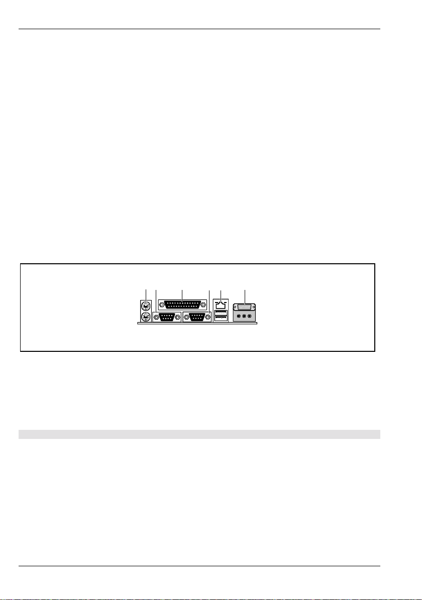
External ports
31 4 5
2
1 = PS/2 mouse port
2 = PS/2 keyboard port
3 = Serial port
4 = Parallel port
5 = Serial port
6 = LAN port
The components and connectors m arked are not necessarily present on the system board.
4 - English A26361-D1332-Z120-1-7419
6
8
7
9a 9c9b
7 = USB ports A and B
8 = Game/Midi port
9a = Audio Line-Out / Headphones
9b = Audio Line-In
9c = Audio Micro-In
Page 13
Internal ports and connectors
Features
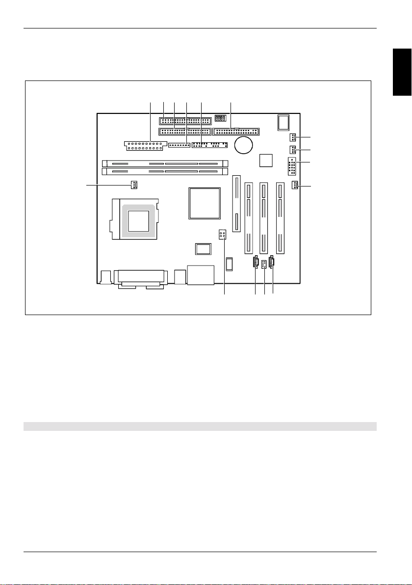
1234 6
5
7
8
DIMM 2
DIMM 1
15
1 = Power supply
2 = Floppy Disk Drive
3 = IDE drives 3 and 4 (secondary)
4 = Power supply monitoring
5 = Connector for control panel and
loudspeaker
AGP
PCI 1
14
PCI 3
PCI 2
1213
11
10 = Wake On LAN
11 = CD audio input
12 = Audio front panel
13 = AUX audio input
14 = Power supply +12 V
15 = Fan 1 (e.g. for the processor)
9
10
6 = IDE drives 1 and 2 (primary)
7 = Fan 2
8 = Cover monitoring
9 = USB ports C and D
The components and connectors m arked are not necessarily present on the system board.
A26361-D1332-Z120-1-7419 English - 5
Page 14

Features
Temperature / System monitoring
Temperature and system monitoring aim to reliably protect the computer hardware against damage
caused by overheating. In addi tion, any unnecessary noise is also prevented by reduci ng the fan
speed, and information is prov i ded about the system status. Cover monitoring protects the system
from unauthorised opening.
An onboard controller developed by Fujitsu Siemens Computers c ontrols the temperature and
system monitoring.
The following functions are s upported:
Temperature monitoring:
Measurement of the process or and the system temperature with an onboard temperature sensor.
Temperature control:
The temperature is controlled by adj usting the fan speed and/or by reduci ng the clock frequency of
the processor. The clock frequency of the process or i s dependent upon the setting in the BIOS Setup.
Temperature-dependent processor speed control enables a reduced fan speed, decreasing noise.
Fan monitoring:
Fans which have been removed, bloc ked or sticky fans are detected. Blocked or sticky fans are
operated with 12 V pulse voltage. If the system has a monitored fan removed while the system is
switched off this i s indicated by the mess age LE D when the system is switched on again and
processed by the BIOS or the application.
Fan control:
With the exception of the auxiliary fan (AUX), the fans are regulated according to temperature.
Sensor monitoring:
The removal of, or a fault in, a temperature sensor is detect ed. Should this happen all fans
monitored by this sens or run at m aximum speed, to achiev e t he greatest possible protect i on of the
hardware. If the system has a monitored fan removed while the system is switched off this is
indicated by the mess age LE D when the system is switched on again and processed by the BIOS or
the application.
Cover monitoring:
Unauthorised opening of the cover is detected, even when the system is switched off. However, this
will only be indicated when the system is switched on again.
6 - English A26361-D1332-Z120-1-7419
Page 15
Features
Hard disk connection
An ultra ATA/66 or ultra ATA/100 hard disk must be connected with a cable especiall y designed for
the ultra ATA/66or ultra ATA/100 mode.
Ê Connect the end of the cable mark ed wi th blue to the system board.
PCI bus interrupts
The following tabl e shows which PCI bus interrupt s are assigned on the system board.
PCI bus int errupt Component on system board:
B, C, D, A PCI bus sl ot 1
C, D, A, B PCI bus sl ot 2
D, A, B, C PCI bus slot 3
A, B AGP slot
D First US B controller
H Second USB controller
E LAN controller
B SMBus
B AC'97 Audio
A26361-D1332-Z120-1-7419 English - 7
Page 16
Settings with switches and jumpers
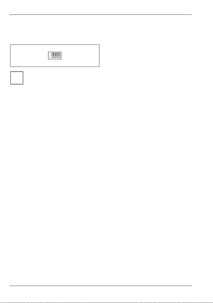
Settings with switches and jumpers
Switch 1 = must always be set to off
ON
1234
The clock frequency of the processor is set automatically.
i
Recovering System BIOS - switch 2
Switch 2 enabl es recovery of the old system BIOS after an attempt to update has failed. To restore
the old system BIOS you need a Flash BIOS Diskett e (pl ease call our customer serv i ce centre).
On The System BIOS ex ecutes from floppy drive A : and the inserted "Flash-BIO S -
Diskette" restores the System BIOS on the system board.
Off Normal operation (default setting).
Defining auxiliary voltage - Switch 4
Switch 4 enables y ou to switch off partly the aux iliary voltage for functions of the system board.
Auxiliary voltage of some power supplies is not sufficient to supply all f unctions of the system board
with auxiliary voltage.
On Wake up on USB is switched off.
Off Normal operation (default setting). All functions are supplied with auxiliary voltage.
Switch 2 = System BIOS recovery
Switch 3 = must always be set to
Switch 4 = Defining auxiliary voltage
off
8 - English A26361-D1332-Z120-1-7419
Page 17
Add-on modules
Exit energy-saving mode, switch off the system and remove the power pl ug from the
mains outlet, before carrying out any of the procedures described in this chapter!
!
Even when you have switched off the system, parts (e.g. memory modules, AGP and PCI
extension boards) are still supplied with power.
All AGP and PCI slots support 3. 3 V main and auxiliary voltages.
Add-on modules
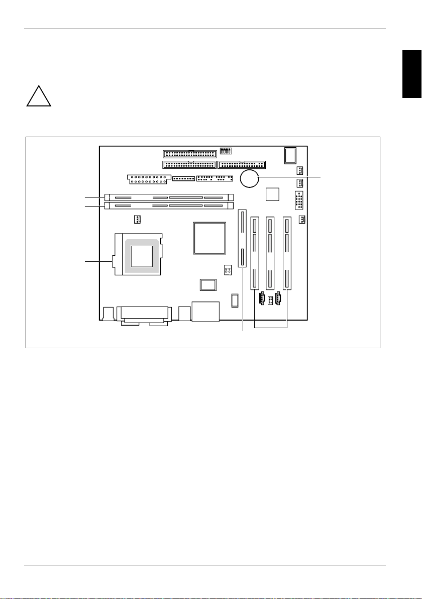
4
3
2
DIMM 2
DIMM 1
1
1 = Socket for processor wit h heat sink
2 = Location bank 1 for main memory
3 = Location bank 2 for main memory
AGP
PCI 1
4 = Lithium battery
5 = PCI slots 1, 2, 3
6 = AGP slot
PCI 3
PCI 2
56
A26361-D1332-Z120-1-7419 English - 9
Page 18
Add-on modules
Installing and removing processors
a
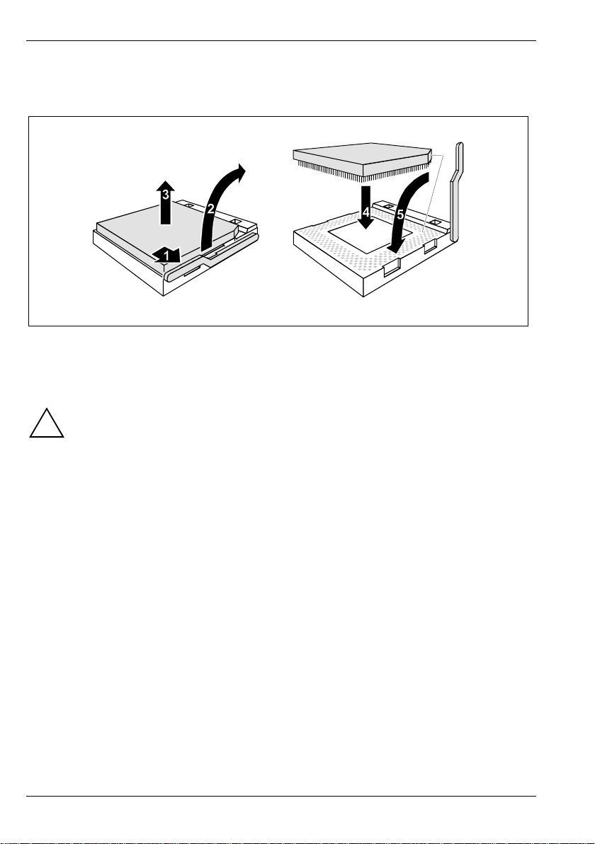
Ê Pull the lever in the direction of the arrow (1) and lift it as far as it will go (2).
Ê Remove the old processor from the socket (3).
Ê Insert the new processor in the socket so that t he angl ed corner of the processor matc hes the
coding on the socket (A) wi th regard to the position (4).
The angled corner of the processor may be covered by the heat sink. I n this case let
yourself be guided by the mark i ng i n the rows of pins on the underside of t he processor.
!
Ê Push the lever back down until it clicks into place (5).
10 - English A26361-D1332-Z120-1-7419
Page 19
Add-on modules
Upgrading main memory
These slot s are suitable for DIMM format 64, 128, 256, 32, 512 and 1024 MB DDR memory
modules.
Memory modules with different memory capacities can be combi ned.
You may only use unbuffered 2.5V memory modules. Buffered memory modules are not
supported.
!
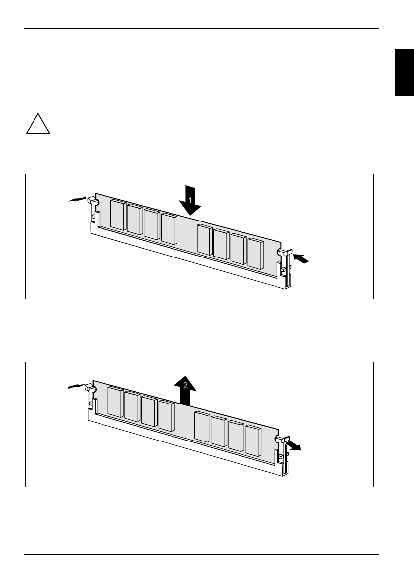
Installing a memory module
DDR memory modules must meet the PC2100 specification.
2
2
Ê Push the holders on each side of the memory compartment outwards.
Ê Insert the memory module i nto the location (1).
Ê At the same time fl i p the lateral holders upwards until the m e m ory module snaps in place (2).
Removing a memory module
1
1
Ê Push the clips on the right and left of the compartment outward (1).
Ê Carefully remove the memory module from the compartment (2).
A26361-D1332-Z120-1-7419 English - 11
Page 20
Add-on modules
Installing network board with WOL
Ê Install the network board as described in the operating manual for your uni t.
Ê Push the WOL cable onto the WOL plug connector of the system board.
To use the WOL functionality of a network board the power supply mus t provide a
5 V auxiliary voltage of at least 1 A . If the system board was not already
i
incorporated in a device when you bought i t you must check whether y our power
supply can provide the auxiliary volt age.
You may find further inform ation in the supplied description of the network board.
12 - English A26361-D1332-Z120-1-7419
Page 21
Replacing the lithium battery
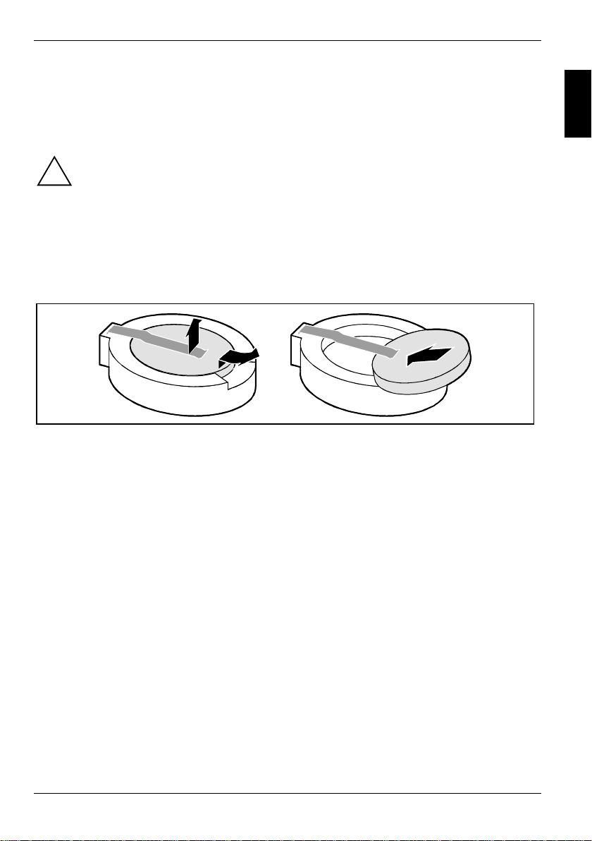
Incorrect replacement of the lithium battery may l ead to a risk of explosion.
!
The lithium battery must be replaced with an identical bat t ery or a battery type
recommended by the manufact urer (CR2032).
Do not throw lithium batteries into the household waste. They m ust be disposed of in
accordance with local regulations concerning special waste.
Ensure that you insert t he battery the right way round. The plus pol e m ust be on the top!
This representation is also valid for a v ertically built-in lithium battery.
Add-on modules
1
+
+
Ê Lift the contact (1) a few millimetres and remove the battery from its soc ket (2).
Ê Insert a new lithium batt ery of the same type into t he socket (3).
2
+
3
+
A26361-D1332-Z120-1-7419 English - 13
Page 22
Glossary
Glossary
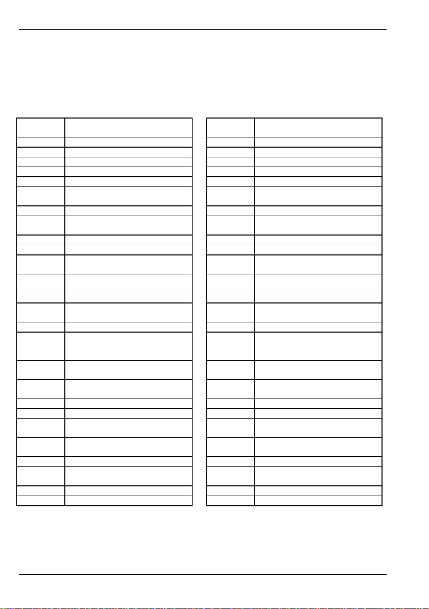
The technical terms and abbrevi ations given below represent only a selection of the full li st of
common technical term s and abbreviations. Not all technical terms and abbreviations listed here are
valid for the described system board.
ACPI Advanced Configuration and
Power Management Interface
AC'97 Audio Codec '97 ISA Industrial Standard Archi tecture
AGP Accelerated Graphics P ort LAN Local Area Network
AMR Audio Modem Riser LSA LAN Desk Service Agent
AOL Alert On LAN MCH Memory Controller Hub
APM Advanc ed P ower Management MMX MultiMedia eXtension
ATA Advanced Technology
Attachment
BIOS Basic Input Output System P64H PCI64 Hub
CAN Controller Area Network PCI Peripheral Com ponent
CPU Central Processing Unit PXE Preboot eXecution Environment
CNR Communication Network Riser RAM Random Access Memory
C-RIMM Continuity Rambus Inli ne
Memory Module
DDR Double Data Rat e RDRAM Rambus Dynamic Random
DIMM Dual Inline Memory M odul e RIMM Rambus Inline Memory Module
DRAM Dynamic Random Access
Memory
ECC Error Correcting Code SB Soundblaster
EEPROM Electrical Erasable
Programmable Read Only
Memory
FDC Floppy Di sk Controller SGRAM Synchronous Graphi c Random
FIFO First-In Firs t -Out SIMD Streaming Mode I ns truction
FSB Front Side Bus SMBus System Management Bus
FWH Firmware Hub SVGA Super Video Graphic Adapter
GMCH Graphics and Memory Controller
Hub
GPA Graphics Performance
Accelerator
I2C Inter I nt egrated Circuit WOL Wake On LAN
IAPC Instantly Avai l abl e P ower
Managed Desktop PC Design
ICH I/O Controller Hub
IDE Intell i gent Dri ve Electronics
IPSEC Internet Protocol Security
NIC Networking Interface Card
Interconnect
RAMDAC Random Access Memory Digital
Analogue Converter
Access Memory
RTC Real Time Cloc k
SDRAM Synchronous Dynamic Random
Access Memory
Access Memory
(Single Instruction Multiple Data)
USB Universal Serial Bus
VGA Video Graphic Adapter
14 - English A26361-D1332-Z120-1-7419
 Loading...