

Page 1
COMPONENT
.com Technisches Handbuch / Technical Manual
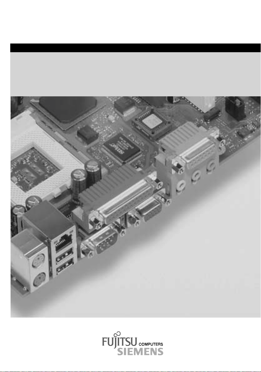
Systembaugruppe D1329 / System board D1329
Page 2

Sie haben ...
... technische Fragen oder Probleme?
Wenden Sie sich bitte an:
· Ihren zuständigen Vertriebs part ner
· Ihre Verkaufsst elle
Weitere Informationen finden Si e i m Handbuch "Sicherheit, Garantie und E rgonom i e" .
Aktuelle Informationen zu unseren Produkten, Tipps, Updates usw. finden Sie im Internet:
http://www.fujitsu-siemens.com
Are there ...
... any technical problems or other questions you need clarified?
Please contact:
· your sales partner
· your sales outlet
You will find further information in the manual "Safety, Guarantee and Ergonomics".
The latest information on our produc t s, tips, updates, etc., can be found on the Internet under:
http://www.fujitsu-siemens.com
Page 3

Page 4
Dieses Handbuch wurde auf Recycling-Papier gedruckt.
This manual has been printed on recycled paper.
Ce manuel est imprimé sur du papier recyclé.
Este manual ha sido impreso sobre papel reciclado.
Questo manuale è stato stampato su carta da riciclaggio.
Denna handbok är tryckt på recyclingpapper.
Dit handboek werd op recycling-papier gedrukt.
Herausgegeben von/Published by
Fujitsu Siemens Computers GmbH
Bestell-Nr./Order No.:
Printed in the Federal Republic of Germany
AG 1101 11/01
A26361-D1329-Z120-1-7419
A26361-D1329-Z120-1-7419
Page 5
Systembaugruppe
D1329
System Board D1329
Technisches Handbuch
Technical Manual
Deutsch
English
Ausgabe November 2001
November 2001 edition
Page 6

Intel, Pentium und Celeron s i nd ei nget ragene der Intel Corporation, USA.
Microsoft, MS, MS-DOS und Windows sind eingetragene Warenzeichen der Microsoft
Corporation.
PS/2 und OS/2 Warp sind eingetragene Warenz ei chen von International Business Machines,
Inc.
Alle weiteren genannten Warenzeichen s i nd Warenzeichen oder eingetragene Warenzeichen
der jeweiligen Inhaber und werden als geschüt zt anerkannt.
Alle Rechte vorbehalten, i nsbesondere (auch auszugsweise) di e der Übersetzung, des
Nachdrucks, der Wiedergabe durch Kopieren oder ähnliche Verfahren.
Zuwiderhandlungen verpflichten zu S chadenersatz.
Alle Rechte vorbehalten, insbesondere für den Fall der Patenterteil ung oder GM -Eintragung.
Liefermöglichkeiten und technische Änderungen vorbehalten.
Dieses Handbuch wurde erstellt von
cognitas. Gesellschaft für Technik-Dokument at i on mbH
www.cognitas.de
Copyright ã Fujitsu Siem ens Computers GmbH 2001
Intel, Pentium and Celeron are registered trademarks of Intel Corporation, USA.
Microsoft, MS, MS-DOS and Windows are registered trademarks of Microsoft Corporation.
PS/2 and OS/2 Warp are registered tradem arks of International Busi ness Machines, Inc.
All other trademarks referenced are trademarks or registered tradem arks of their respectiv e
owners, whose protected rights are acknowledged.
All rights, includi ng ri ghts of translation, reproduc t i on by printing, copying or similar methods,
even of parts are reserved.
Offenders will be liable for damages.
All rights, including rights creat ed by patent grant or registration of a utilit y model or design,
are reserved. Delivery subject to availability.
Right of technical modi f i cation reserved.
This manual was produced by
cognitas. Gesellschaft für Technik-Dokument at i on mbH
www.cognitas.de
Page 7

Contents
Introduction........................................................................................................................................1
Notational conventions ..............................................................................................................1
Important notes..................................................................................................................................1
Information about boards...........................................................................................................2
Features............................................................................................................................................3
External ports............................................................................................................................4
Internal ports and connectors ....................................................................................................5
Temperature / System monitoring..............................................................................................6
Hard disk connection.................................................................................................................7
LAN connector...........................................................................................................................7
PCI bus interrupts...................................................................................................................... 8
Settings with switches and jumpers...................................................................................................9
Recovering System BIOS - switch 2.......................................................................................... 9
Add-on modules ..............................................................................................................................10
Installing and removing processors..........................................................................................11
Upgrading main memory..........................................................................................................12
Installing network board with WOL...........................................................................................13
Replacing the lithium battery....................................................................................................14
Glossary..........................................................................................................................................15
A26361-D1329-Z120-1-7419
Page 8

Page 9
Introduction
Depending on the configuration chosen, some of the hardware components described
may not be available on your system board.
i
You will find further information in the "BIOS Setup" description.
Further information about drivers i s provided in the readme files on t he hard di sk, on the supplied
drivers diskettes, on the "Drivers & Utilities" or on the "ServerStart" CD.
Notational conventions
The meanings of the symbols and fonts used in this manual are as follows:
Pay particular attention to text marked with this symbol. Failure to observe this warning
endangers your life, destroy s the device, or may lead t o l oss of data.
!
Supplementary information, remarks, and tips fol l ow t h i s symbol.
i
Ê Text which follows thi s symbol describes activities that m ust be performed in the order shown.
Ë This symbol indicates that you must enter a blank space (press the Space Bar) at this point.
Ú This symbol indicates that you must press t he Enter key.
Text in this typeface indicates screen output s.
Text in this bold typeface indicates the entries you make via the keyboard.
Text in italics indicates commands or menu items.
"Quotation marks" indicate names of chapters or t erm s.
Important notes
Store this manual clos e to the device. If you pass the device on to third parti es, you should pass this
manual on with it.
Be sure to read this page careful l y and note the information before you open t he device.
!
You cannot access t he system board com ponent s without first opening the device. How
to dismantle and reassembl e t he device is described in the Operating Manual
accompanying the devic e.
Please observe the safety information provided in the "Important notes" chapt er i n the
device’s operating manual.
Incorrect replacement of the lithium battery may l ead to a risk of explosion. It is therefore
essential to observe t he i nstructions in the "Add-on modules" - "Replacing the lit hi um
battery" section.
A26361-D1329-Z120-1-7419 English - 1
Page 10
Important notes
The shipped version of this board complies with the requirements of the EEC
directive 89/336/EEC "Electromagnetic compatibility".
Compliance was tested in a t ypical PC configuration.
When installing the board, refer to the specific installation information in the
Operating Manual or Technical Manual for the receiving device.
Connecting cables for peripherals must be adequately shielded to avoid interference.
Individual components can become very hot during operation. Ensure you do not touch
components when making ext ensions to the system board. There is a danger of burns!
!
The warranty is invalidated if the device is damaged during the i nstallation or
replacement of system expansions. Information on which system expansions you can
i
use is available from y our sales outlet or the cust om er service centre.
Information about boards
To prevent damage to the system board or the components and conductors on it, please t ake great
care when you insert or remove boards. Take great care to ensure that ex t ension boards are slotted
in straight, without dam agi ng components or conductors on t he system board, or any other
components, for example EMI spring contacts.
Be especially careful with the locking mechani sms (catches, c entring pins etc.) when you replac e
the system board or components on it, for example memory modules or processors.
Never use sharp objects (s crewdrivers) for leverage.
Boards with electrost at i c sensitive devices (ESD) are identifiable by the
label shown.
When you handle boards fitted with E SDs, you must, under all
circumstances, observe the following points :
· You must always di scharge static build up (e. g. by touching a
grounded object) before working.
· The equipment and tools you us e m ust be free of static c harges.
· Remove the power plug from the mai ns supply before inserting or
removing boards containing ES Ds.
· Always hold boards wit h ESDs by their edges.
· Never touch pins or conductors on boards fitted wit h E SDs.
2 - English A26361-D1329-Z120-1-7419
Page 11

Features
Features
· System board in ATX format
· mPGA478 Intel processor Pentium 4 wit h 400 M Hz Front Side Bus.
Pentium 4 processors s upport MMX technology and Intel Streaming SIMD Extens i ons. The size and
frequency of first-level cache and second-level cache are dependent upon the processor used.
· Intel chipset 845
· Intel 82562E M LAN controller (10/100 Mbit/s) with RJ45 interface
WOL with Magic Packet ä i s supported, as is booting f rom LAN with Bootix LAN BootP or Intel
PXE.
· Fujitsu Siemens system monitoring and temperature monitoring
· 3 DIMM s l ots for 128 MB to 3 GB main mem ory (SDRAM memory modules m eet the PC133
specification) with ECC
· Flash BIOS
· Power-on functions:
- Wake on RTC
- Wake on LAN
- Wake on PCI Cards (LAN)
- Wake on USB
- Switching on/off vi a software
- COM1 wake up support (standby / soft-off)
· Security functions:
- Processor serial number
- Cover monitoring: cover moni toring reports when the cover has been opened without
authorisation.
- System, Setup and K eyboard password
- parallel and serial ports can be deac t i vated
- Floppy disk write-protect i on via BIOS Setup
- Virus protection function for the boot sector
- Flash BIOS and EEPROMs (on the memory modules) vi rus protection function.
· system monitoring
- Error log for EEPROM
- SMBus (Server Management)
- RSB (Remote Service Board)
- Redundant power supply monitoring
· 6 PCI slots
All PCI slots s upport 3.3 Vand 5 V main voltages.
A26361-D1329-Z120-1-7419 English - 3
Page 12
Features
· 1 AGP slot
The AGP slot supports 1x , 2x and 4x AGP mode. Only A GP boards with 1.5 V are supported.
· IDE hard dis k controller connected to P CI bus for up to four IDE drives
(e.g. IDE hard disk driv es, ATAPI CD-ROM drives )
The IDE hard disk controller are A T A 33/66/100, ultra DMA capable and support PIO modes 0-
4.
· Floppy disk drive controller (possibl e formats: 720 Kbyte, 1. 44 M byte)
· The system board supports booting from a 120 MB IDE floppy disk drive.
· Real-time clock/calendar with integrated battery backup
· 1 internal WOL int erface
· 2 internal USB ports (C / D)
· 1 external parallel port (ECP- and EPP-compatible)
· 2 external s eri al ports (16C550 compatible with FIFO)
· 2 external P S /2 ports for keyboard and mouse
· 2 external US B ports (A / B)
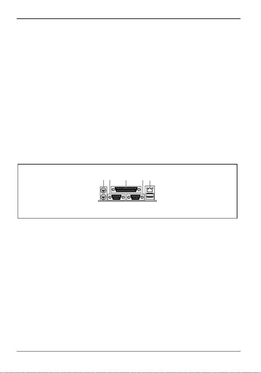
External ports
31 4 5 6
2
1 = PS/2 mouse port
2 = PS/2 keyboard port
3 = Serial interface 1 (COM1)
4 = Parallel port
4 - English A26361-D1329-Z120-1-7419
7
5 = Serial interface 2 (COM2)
6 = LAN connector
7 = USB ports A and B
Page 13
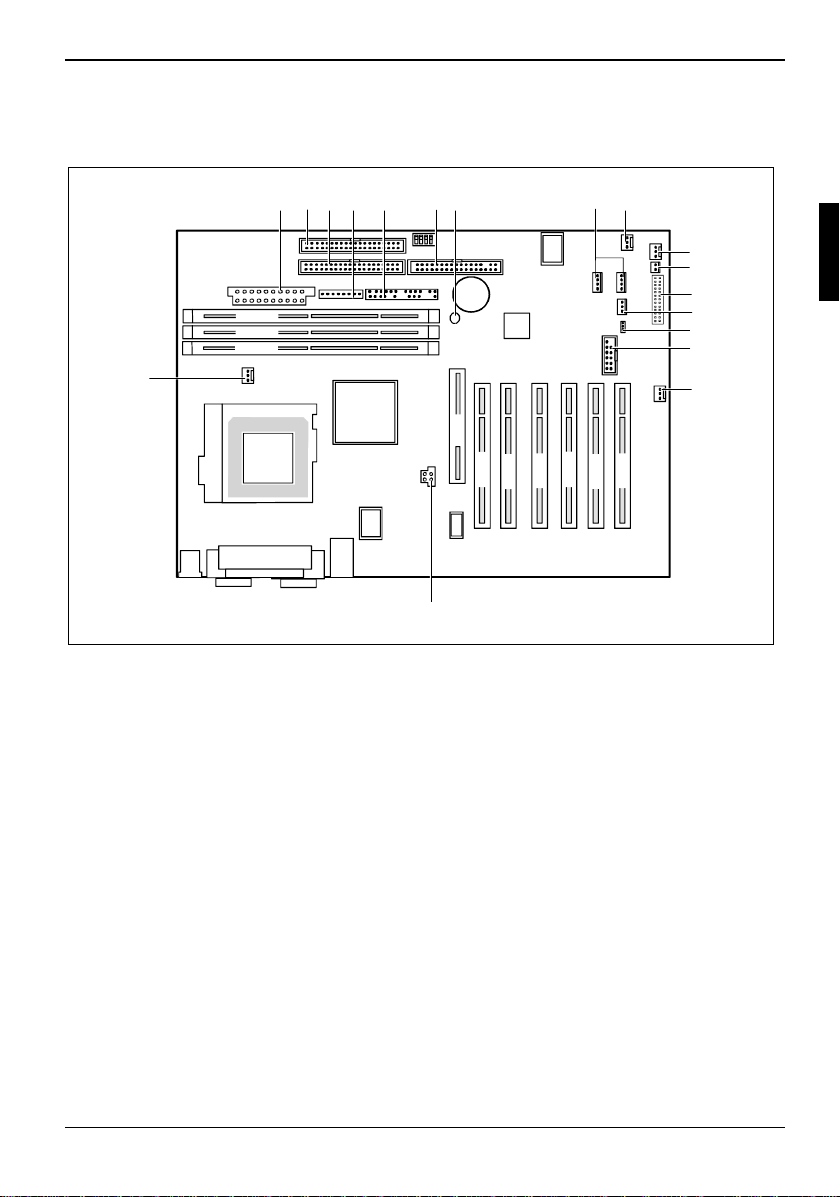
Internal ports and connectors
12
DIMM 3
DIMM 2
DIMM 1
18
567
34
Features
8
9
10
11
12
13
14
15
16
AGP
1 = Power supply ATX
2 = Floppy Disk Drive
3 = IDE drives 3 and 4 (secondary)
4 = Power supply monitoring
5 = Connection for control panel and optical
indicators
6 = IDE drives 1 and 2 (primary)
7 = Voltage indicator LED
8 = SMB 1 / SMB 2
9 = Fan 2 (for the processor fan)
PCI 1
PCI 2
PCI 4
PCI 3
PCI 6
PCI 5
17
10 = Fan 3
11 = VCC_RSB (Remote Service Board)
12 = RSB (Remote Service Board)
13 = Cover monitoring
14 = NMI
15 = USB ports C / D
16 = WOL
17 = Power supply +12 V (for processor)
18 = Fan 1 (for system fan)
A26361-D1329-Z120-1-7419 English - 5
Page 14

Features
Temperature / System monitoring
Temperature and system monitoring aim to reliably protect the computer hardware against damage
caused by overheating. However, unnecessary noise is to be prevented with a fan speed adapted to
the temperature conditions. In addition, important inf orm ation on the operating state of t he device
(temperature, operating voltat e, fan speeds, error states ) i s provided. The cover monitoring system
indicates an unauthorized opening of the device.
These functions are control l ed by an onboard controller developed by Fujit su Siemens Computers.
The following functions are s upported:
Temperature monitoring:
Measurement of the process o r t em perature, measurement of the air te m perat ure upon entry with a
temperature sensor.
Temperature control:
The fan speed of the system fan is controlled depending on the air temperature upon entry. When a
specified temperature lim i t is exceeded, the proces sor clock frequency is also reduced (throttling
mode) to prevent further warming of and dam age to the processor.
Fan monitoring:
Blocked fans or a reduced fan speed due to ageing can be detected with t he f an monitoring
function. Blocked fans are operated with 12 V pulse vol t age. An attempt is made to restart a blocked
system fan with a cyclical voltage pulse. If the system fan is removed with the device switched off,
this results in an error mes sage when the device is swit ched on again. This is indicated optically by
the flashing of the system error LED on the control panel. In addition, an entry is generated in the
BIOS Error Log.
Fan control:
The system fan and power supply fan are controlled in dependence on the temperature.
Sensor monitoring:
The installed sensors are also monitored. If a sensor outputs an impermissible v al ue, this results in
an increase in the fan speed to t he m aximum value in order to ensure the maximum possible
protection of the hardware.
A failed sensor results in an error message. This is i ndi cated optically by the flashing of the system
error LED on the control panel. In addit i on, an entry is generated in the BIOS Error Log.
Cover monitoring:
Unauthorised opening of the cover is detected, even when the system is switched off. However, this
will only be indicated when the system is switched on again.
This procedure generates an entry in t he B IOS Error Log.
6 - English A26361-D1329-Z120-1-7419
Page 15
Features
Voltage monitoring:
The voltages 12 V, 5 V and the CMOS battery are monitored.
If the voltage lies out side the specified tolerances, an error message is generated. Thi s is indicated
optically by the flashing of the system error LED on the control panel. In addition, an entry is
generated in the BIOS Error Log.
Advantages of hardware system monitoring
With hardware monitoring - regardless of the operating system and processor - the advantages
compared to conventional s of tware monitoring are clear:
- suitable for all operati ng systems and proces sor types
- no additional load on processor (performance)
- optimum temperature protection, even if process faults or faults are present i n the
operating system
- optimum noise reducti on
Hard disk connection
The system is equipped with two independent Ultra ATA/100 interfac es. An Ultra ATA/100 hard disk
must be connected with a special IDE cable (80-wire, 40-pin).
Ê Connect the end of the cable mark ed wi th blue to the system board.
Ê Insert the socket of the IDE cable marked in blue in one of the two blue plugs on the system
board.
LAN connector
The system board has an Intel 82562EM LAN controller. The LAN c ont rol l e r i s equipped with a 3 KB
transmission and receiv i ng buffer (FIFO) and supports WOL funct i on through Magic Packetä.
In addition, Bootix LAN BootP and Intel PXE are also supported (s upport of systems without hard
disks).
Basic AOL II is al so supported. Basic AOL II helps to protect systems against t heft or damage.
Basic AOL II can al so inform the administrat or about hardware faults and software errors.
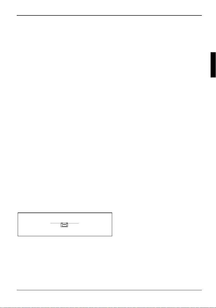
The LAN RJ45 connector is equipped wi t h a yellow and a green LED (light emitti ng di ode).
1 = Yellow indicator
2
1
Yellow a connection exists (e.g. to a hub).
Green Link Mode: the LAN connection is active.
WOL mode: a Magic Packet
A26361-D1329-Z120-1-7419 English - 7
2 = Green indicator
TM
is being received.
Page 16
Features
PCI bus interrupts
The following table shows which PCI bus interrupts are assi gned on the system board.
PCI bus interrupt Component on system board:
B, C, D, A PCI bus slot 1
C, D, A, B PCI bus slot 2
D, A, B, C PCI bus slot 3
E, F, G, H PCI bus slot 4
F, G, H, A PCI bus slot 5
G, H, A, B PCI bus slot 6
A, B AGP slot
D First USB controller
H Second USB controller
E LAN controller
BSMBus
8 - English A26361-D1329-Z120-1-7419
Page 17
Settings with switches and jumpers
Settings with switches and jumpers
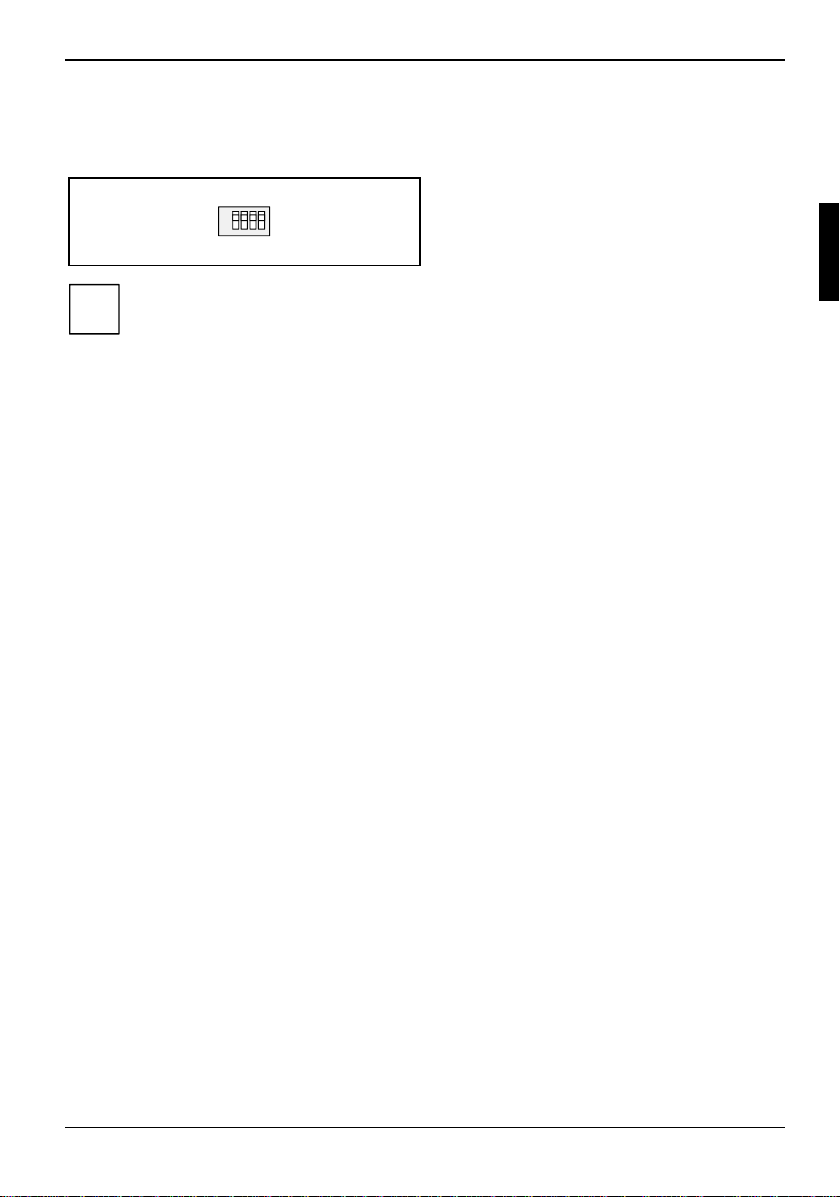
Switch 1 = must always be set to off
ON
1234
The clock frequency of the processor is set autom atically.
i
Recovering System BIOS - switch 2
Switch 2 enables recovery of the old system BIOS after an attempt to update has failed. To restore
the old system BIOS you need a Flash BIOS Diskette (please call our customer service centre).
On The System BIOS ex ecutes from floppy drive A : and the inserted "Flash-BI OS -
Off Normal operation (default setting).
Diskette" restores the System BIOS on the system board.
Switch 2 = System BIOS recovery
Switch 3 = must always be set to
Switch 4 = must always be set to off
off
A26361-D1329-Z120-1-7419 English - 9
Page 18
Add-on modules
Add-on modules
Exit the operating system and wait until the device has switched off. Pull the power plug
out of the mains outlet!
!
Even with the system switched off, certain parts of the device (e.g. memory modules,
AGP and PCI expansion boards) may st ill be energised. This is indicated by the red
voltage indicator LED next to the battery. These components may only be replaced when
the voltage indicator LED i s not lit up.
All PCI slots are s uppl i ed wi th both 3.3 V and 5 V main voltage. The A G P slot is supplied
with 1.5 V main voltage.
4
3
2
DIMM 3
DIMM 2
DIMM 1
1
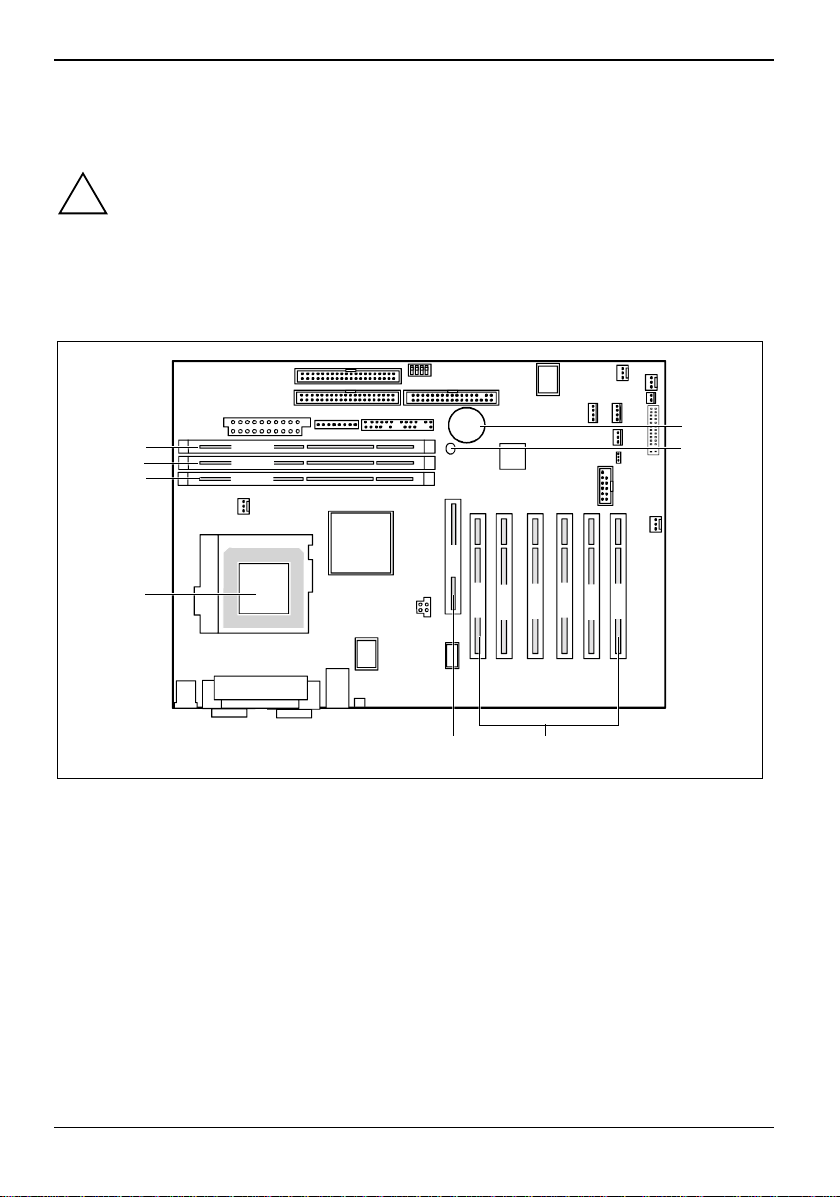
1 = Socket for processor wit h heat sink
2 = Location bank 1 for main memory
3 = Location bank 2 for main memory
4 = Location bank 3 for main memory
AGP
PCI 1
PCI 2
8
PCI 4
PCI 3
7
5 = Lithium battery
6 = Voltage indicator LED
7 = PCI slots 1, 2, 3, 4, 5, 6
8 = AGP slot
5
6
PCI 6
PCI 5
10 - English A26361-D1329-Z120-1-7419
Page 19
Add-on modules
Installing and removing processors
2
2
3
3
1
1
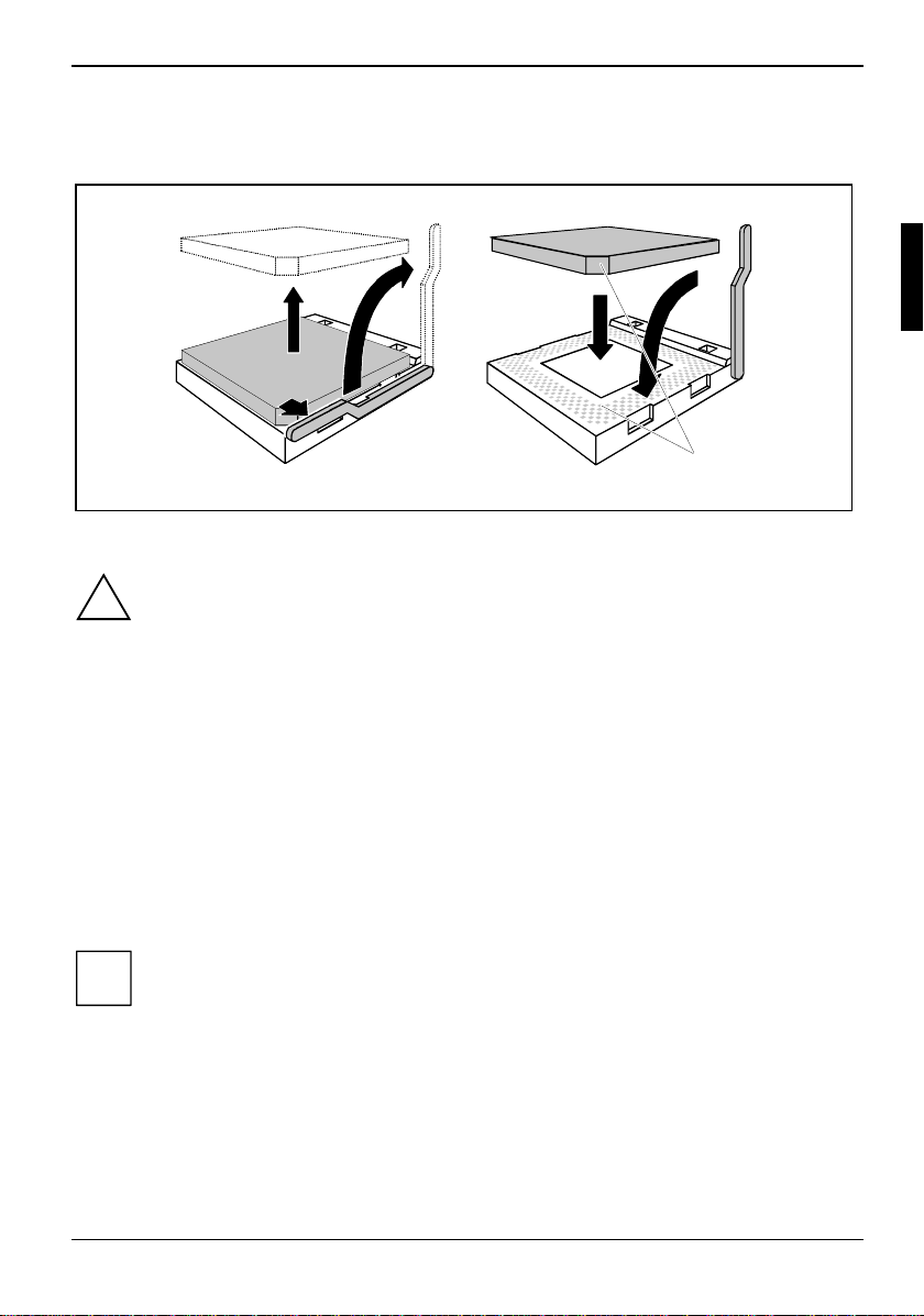
Before you install or remov e the processor, you must rem o ve the processor heat sink .
Processor heat sinks can become very hot.
!
Wait until the processor heat sink has cooled before remov i ng i t.
Ê Release the bracket for the processor heat sink.
Ê Lift the heat sink off the processor and lay the heat sink aside.
Ê Pull the lever in the direction of the arrow (1) and lift it as far as it will go (2).
Ê Remove the old processor from the socket (3).
Ê Insert the new processor in the socket so that t he angl ed corner of the processor matc hes the
coding on the socket (A) wi th regard to the position (4).
Ê Push the lever back down until it clicks into place (5).
Ê Before you refit the proces sor heat sink, carefull y remove the residues of the heat conducting
paste from the surface of the processor heat sink.
Ê Apply an even coat of new heat c onducting paste to the entire s urface of the processor or use
a new heat conducting pad.
4
4
5
5
A
A
If you upgrade your device wit h a new processor, it is advi sable to also replace the
processor fan at the same time. This serves to increase the reliability of the entire system
i
(preventative protecti on).
A26361-D1329-Z120-1-7419 English - 11
Page 20
Add-on modules
Upgrading main memory
These slots are suitable for 128, 256, 512, 1024 Mbyte SDRAM m em ory modules of the DIMM
format.
Memory modules with different memory capacities can be combined.
You may only use unbuffered 3. 3 V memory modules. Buffered m emory modules are not
allowed and lead to a device failure.
!
SDRAM memory modules must meet the PC133 specif i cation.
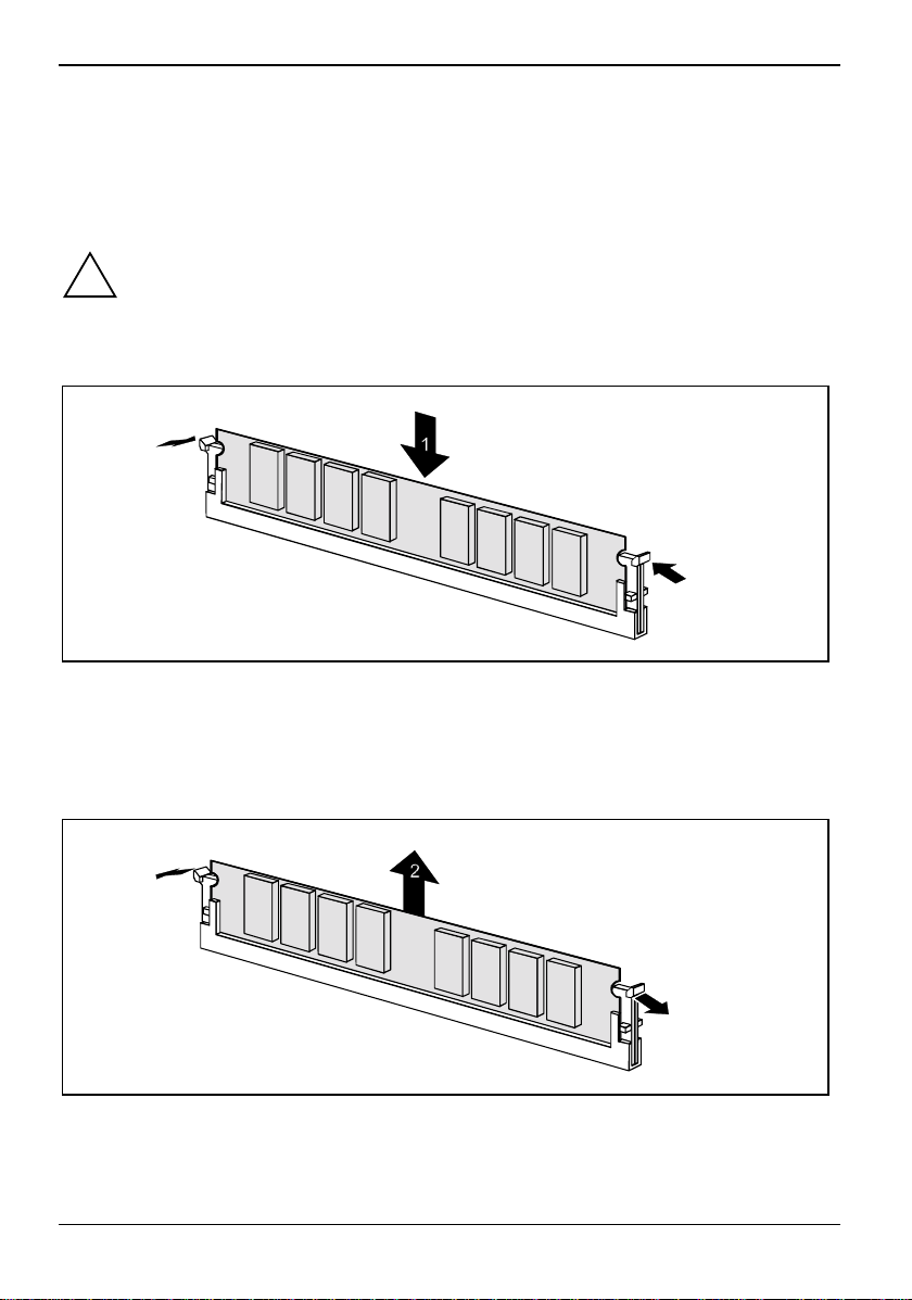
Installing a memory module
2
2
Ê Push the holders on each side of the memory compartment outwards.
Ê Push the memory module int o t he l o cation (1).
Ê At the same time fl i p t he both lateral holders upwards until t he m em ory module snaps in
place (2).
Removing a memory module
1
1
Ê Push the clips on the right and left of the compartment outward (1).
Ê Carefully remove the memory module from the compartment (2).
12 - English A26361-D1329-Z120-1-7419
Page 21

Add-on modules
Installing network board with WOL
Ê Install the network board in a free PCI slot.
The system board supports the PME cable, which replac es the additional WOL connector wit h
cable.
However, if you want to install a network board without PME signalling, you mus t connect the WOL
cable to the system board.
Ê Connect the WOL cable onto the WOL connec tor of the system board.
You may find further inform ation in the supplied descript i on of the network board.
A26361-D1329-Z120-1-7419 English - 13
Page 22
Add-on modules
Replacing the lithium battery
Incorrect replacement of the lithium battery may l ead to a risk of explosion.
!
The lithium battery must be replaced with an identical bat t ery or a battery type
recommended by the manufact urer (CR2032).
Do not throw lithium batteries into the household waste. They m ust be disposed of in
accordance with local regulations concerning special waste.
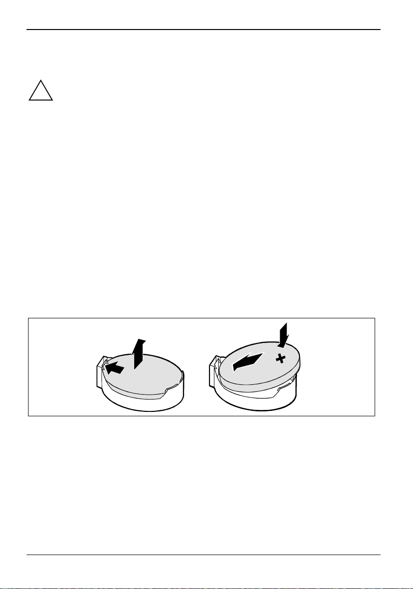
Ensure that you insert t he battery the right way round. The plus pol e m ust be on the top!
· VAROITUS
Paristo voi räjähtää, jos se on virheellisesti asennettu. Vaihda paristo ainoastaan
laitevalmistajan suosittelemaan tyyppi i n. Hävitä käytetty paristo valmistaj an
ohjeiden mukaisesti.
· VARNING
Explosionsfara vid felaktigt batteriby t e. Använd samma batterit yp eller en ekvivalent
typ som rekommenderas av apparattillverkaren. Kassera använt batteri enligt
fabrikantens instruk tion.
· ADVARSEL
Lithiumbatteri - Explosionsfare ved fejlagtig håndt ering. Udskiftning må kun ske med
batteri af samme fabrik at og type. Lever det brugte batteri tilbage til leverandøren.
· ADVARSEL
Explosionsfare ved feilaktig skifte av batteri. Benytt samme batteritype eller en
tilsvarende type anbefalt av apparatfabrikanten. Bruk te batterier kasseres i henhol d
til fabrikantens ins truksjoner.
The following graphic representation i s also valid if the lithium battery is built-in vertically.
4
2
1
3
+
Ê Press the retaining spring i n the direction of the arrow (1) until y ou can remove the lithium
battery from the holder (2).
Ê Push the new lithium batt ery of the identical type i nto the holder (3) and make sure it
engages (4).
14 - English A26361-D1329-Z120-1-7419
Page 23
Glossary
Glossary
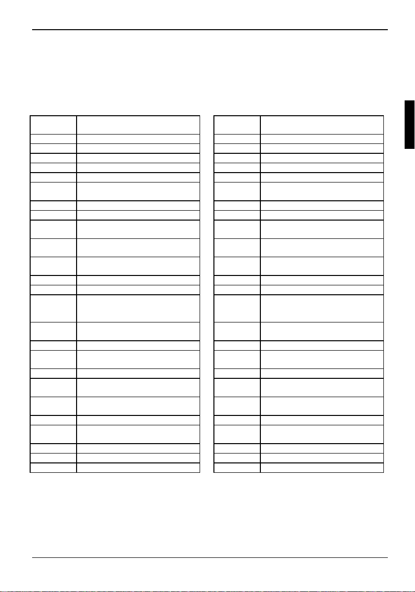
The technical terms and abbrevi ations given below represent only a selection of the full li st of
common technical term s and abbreviations.
Not all technical terms and abbreviations list ed here are valid for the described system board.
ACPI Advanced Configuration and
Power Management Interface
AC'97 Audio Codec '97 LAN Local Area Network
AGP Accelerat ed Graphics Port LSA LAN Desk Service Agent
AMR Audio Modem Riser MCH Memory Cont rol ler Hub
AOL Alert On LAN MMX MultiMedia eXtension
APM Advanced Power Management P64H PCI64 Hub
ATA Advanced Technology
Attachment
BIOS Basic Input Output System PXE P reboot eXecution Environment
CAN Controller Area Net work RAM Random Access Memory
CPU Central Processing Unit RAMDAC Random Access Memory Digital
CNR Communication Network Riser RDRAM Rambus Dynamic Random
C-RIMM Continuity Rambus Inli ne
Memory Module
DIMM Dual Inline Memory Modul e RTC Real Time Clock
ECC Error Correcting Code SB Soundblaster
EEPROM Electrical Erasable
Programmable Read Only
Memory
FDC Floppy Disk Controller SGRAM Synchronous Graphi c Random
FIFO First-In First-Out
FSB Front Side Bus SIMD Streaming Mode Instruction
FWH Firmware Hub SMBus System Management Bus
GMCH Graphics and Memory Control ler
Hub
GPA Graphics Perf orm ance
Accelerator
I2C Inter I nt egrated Circuit VGA Video Graphic Adapt er
IAPC Instantly Avai l abl e P ower
Managed Desktop PC Design
ICH I/O Controller Hub
IDE Intelligent Drive Electronics
IPSEC Internet Protocol Security
ISA Industrial Standard Archi tecture
PCI Peripheral Component
Interconnect
Analogue Converter
Access Memory
RIMM Rambus Inline Memory Module
SDRAM Synchronous Dynamic Random
Access Memory
Access Memory
(Single Instruction Multiple Data)
SVGA Super Video Graphic Adapter
USB Universal Serial Bus
WOL Wake On LAN
A26361-D1329-Z120-1-7419 English - 15
 Loading...