

Page 1
COMPONENT
.com Technisches Handbuch / Technical Manual
Systembaugruppe / System board D1309
Page 2

Sie haben ...
... technische Fragen oder Probleme?
Wenden Sie sich bitte an:
· Ihren zuständigen Vertriebs part ner
· Ihre Verkaufsstell e
Weitere Informationen finden Si e i m Handbuch "Sicherheit und Ergonomie".
Aktuelle Informationen zu unseren Produkten, Tipps, Updat es usw. finden Sie im Internet:
http://www.fujitsu-siemens.com
Are there ...
... any technical problems or other questions you need clarified?
Please contact:
· your sales partner
· your sales outlet
You will find further information in the manual "Safety and E rgonomics".
The latest information on our produc t s, tips, updates, et c., can be found on the Internet under:
http://www.fujitsu-siemens.com
Page 3

Page 4

Dieses Handbuch wurde auf Recycling-Papier gedruckt.
This manual has been printed on recycled paper.
Ce manuel est imprimé sur du papier recyclé.
Este manual ha sido impreso sobre papel reciclado.
Questo manuale è stato stampato su carta da riciclaggio.
Denna handbok är tryckt på recyclingpapper.
Dit handboek werd op recycling-papier gedrukt.
Bestell-Nr./Order No.:
Printed in the Federal Republic of Germany
AG 0402 04/02
A26361-D1309-Z120-1-7419
A26361-D1309-Z120-1-7419
Page 5
Systembaugruppe
D1309
System board D1309
Technisches Handbuch
Technical Manual
Deutsch
English
Ausgabe April 2002
April 2002 edition
Page 6

Intel ist ein eingetragenes Warenzeichen der Intel Corporation, USA .
PS/2 ist ein eingetragenes Warenzeichen von International Bus i ness Machines, Inc.
Alle weiteren genannten Warenzeichen s i nd Warenzeichen oder eingetragene Warenzeichen
der jeweiligen Inhaber und werden als geschüt zt anerkannt.
Alle Rechte vorbehalten, i nsbesondere (auch auszugsweise) die der Übersetzung, des
Nachdrucks, der Wiedergabe durch Kopieren oder ähnliche Verfahren.
Zuwiderhandlungen verpflichten zu S chadenersatz.
Alle Rechte vorbehalten, insbesondere für den Fall der Patenterteilung oder GM -Eintragung.
Liefermöglichkeiten und technische Änderungen vorbehalten.
Copyright ã Fujitsu Siem ens Computers GmbH 2002
Intel is a registered tradem ark of Intel Corporation, USA.
PS/2 is a registered tradem ark of International Busines s Machines, Inc.
All other trademarks referenced are trademarks or registered trademarks of their respectiv e
owners, whose protected rights are acknowledged.
All rights, includi ng ri ghts of translation, reproduction by printing, copying or s i m i l ar m ethods,
even of parts are reserved.
Offenders will be liable for damages.
All rights, including rights creat ed by patent grant or registration of a utilit y model or design,
are reserved. Delivery subject to availability.
Right of technical modi f i cation reserved.
Page 7

Contents
Introduction........................................................................................................................................1
Notational conventions ..............................................................................................................1
Important notes..................................................................................................................................1
Information about boards...........................................................................................................2
Features............................................................................................................................................3
Interfaces and connectors..........................................................................................................4
Temperature / System monitoring.............................................................................................. 5
LAN connector...........................................................................................................................6
ISA bus resources.....................................................................................................................6
PCI bus resources.....................................................................................................................7
Screen resolution.......................................................................................................................8
Settings with switches.......................................................................................................................9
Recovering System BIOS - switch 1..........................................................................................9
Skipping the password query - switch 2.....................................................................................9
Write protection for Flash BIOS - switch 3.................................................................................9
Write protection for floppy di sks - switch 4.................................................................................9
Add-on modules ..............................................................................................................................10
Slot sequence..........................................................................................................................11
Upgrading main memory..........................................................................................................11
Replacing the lithium battery....................................................................................................13
Glossary..........................................................................................................................................14
A26361-D1309-Z120-1-7419
Page 8

Page 9
Introduction
This Technical Manual descri bes the system board D1309, which can be equipped with up to two
Intel Xeon processors.
You will find further information in the "BIOS Setup" description.
Further information about drivers is provided in the readme f iles on the hard disk, on the suppli ed
drivers diskettes, on the "Drivers & Utilities" or on the "ServerStart" CD.
Notational conventions
The meanings of the symbols and fonts used in this manual are as follows:
Pay particular attention to text marked with this symbol. Failure to observe this warning
endangers your life, destroy s the device, or may lead to l oss of data.
!
Supplementary information, remarks, and tips foll ow this symbol.
i
Ê Text which follows this symbol describes activiti es that must be performed in the order s hown.
Ë This symbol indicat es that you must enter a blank space (press the Space Bar) at this point.
Ú This symbol indicates that you must press the Enter key.
Text in this typeface indicates screen output s.
Text in this bold typeface indicates the entries you make via the keyboard.
Text in italics indicates commands or menu items.
"Quotation marks" indicate names of chapters or term s.
Important notes
Store this manual clos e to the device. If you pas s the device on to third parties , you should pass this
manual on with it.
Be sure to read this page careful l y and note the information before you open t he device.
!
You cannot access t he system board com ponent s without first opening the device. How
to dismantle and reassembl e t he device is described in the Operat i ng M anual
accompanying the devic e.
Please observe the safety information provided in the " I mportant notes" chapter in the
device’s operating manual.
Incorrect replacement of the lithium battery may l ead t o a ri sk of explosion. It i s therefore
essential to observe t he i nstructions in the "Add-on m odul es" - "Replacing the lithium
battery" section.
A26361-D1309-Z120-1-7419 English - 1
Page 10
Important notes
The shipped version of this board complies with the requirements of the EEC
directive 89/336/EEC "Electromagnetic compatibility".
Compliance was tested in a t ypical PC configuration.
When installing the board, refer to the specific installation information in the
Operating Manual or Technical Manual for the receiving device.
Connecting cables for peripherals must be adequately shielded to av oi d i nterference.
Components can become very hot during operation. Ensure you do not touch
components when making ext ensions to the system board. There is a danger of burns!
!
The warranty is invalidated if the device is damaged during the installation or
replacement of system expansions. Information on which system expansions you can
i
use is available from y our sales outlet or the custom er service centre.
Information about boards
To prevent damage to the system board or the components and conductors on it, please take great
care when you insert or remove boards. Take great care to ensure that extension boards are slotted
in straight, without dam agi ng components or conductors on the system board, or any other
components, for example EMI spring contacts .
Be especially careful with the locking mechanisms (catches, centring pins etc.) when you replace
the system board or components on it, for example memory modules or processors.
Never use sharp objects (s crewdrivers) for leverage.
Boards with electrost at i c sensitive devic es (ESD) are identifiable by the
label shown.
When you handle boards fitted with E SDs, you must, under all
circumstances, observe the following points :
· You must always discharge static build up (e.g. by touching a
grounded object) before working.
· The equipment and tools you use mus t be free of static charges .
· Remove the power plug from the mains supply before inserting or
removing boards containing ES Ds.
· Always hold boards with ESDs by their edges.
· Never touch pins or conduct ors on boards fitted with ESDs .
2 - English A26361-D1309-Z120-1-7419
Page 11

Features
Features
· ServerWorks GC LE chipset
· two processor slots for Xeon (Prestonia) processors with 2.2 GHz and higher, sock et 603, with
100 MHz Front Side Bus
· 512 Kbyte second level c ache
· 6 memory slots for P C1600 m odul es (registered DDR SDRAM memory m odul es) for
256 Mbyte to 12 Gbyte main memory
· two 64 bit PCI-X slots wi th 100 MHz
· two 64 bit PCI slots wi th 66 MHz
· one 32 bit PCI slot with 33 MHz
· one 32 bit PCI slot with 33 MHz (short design)
· SCSI controller LSI 53C1000R onboard wi t h Ul tra160 SCSI interface and 64 bit/ 66 MHz PCI
interface
· Screen controller ATI Rage X L VGA onboard with 230 MHz RAMDAC and 8 Mby t e SDRAM
memory
· Intel 82559PM LAN controll er
· Server Management with Scylla (SM ASIC) onboard
· IDE controller ATA100 capabl e, supports PIO mode 0-4
· one external parallel interface (ECP- and EPP-compatible)
· two external serial ports (COM 1 and COM 2)
· two external and one internal USB1. 1 port
· one external RJ45 LAN port
· two external PS/2 interf aces for keyboard and mouse
· system monitoring
A26361-D1309-Z120-1-7419 English - 3
Page 12
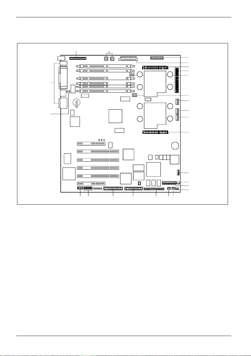
Features
Interfaces and connectors
26 27
25
24
PCI 6
PCI 5
PCI 4
PCI 3
PCI 2
PCI 1
1
2345678
Bank 2 – Module B
Bank 2 – Module A
Bank 1 – Module B
Bank 1 – Module A
Bank 0 – Module B
Bank 0 – Module A
CPU 0
CPU 1
1
2
3
4
5
6
7
8
9
10
11
12
13
14
15
16
181920212223
17
1 = PC98
2 = Power supply
3 = Voltage regulator module (VRM) CPU 0
4 = Connector for front panel
5 = Fan connector for CPU 0
6 = Fan connector for CPU 1
7 = Connector LCD display
8 = Connnector for casing ID EEPROM
9 = Connector PS backplane
10 = Voltage regulator module (VRM)
CPU 1
11 = Power monitoring
12 = Connector bus multiplexer
15 = Connector RSB signals
16 = Monitoring of the position of the door
17 = System fan 2
18 = System fan 1
19 = SCSI connection
20 = IDE drives (primary)
21 = IDE drives (sec ondary)
22 = Switch block
23 = Internal USB port for chipcard reader
24 = Wake On LAN
25 = External ports
26 = Floppy Disk Drive
27 = Power supply 12 V
13 = Connector NMI key
14 = Connector RSB power
4 - English A26361-D1309-Z120-1-7419
Page 13
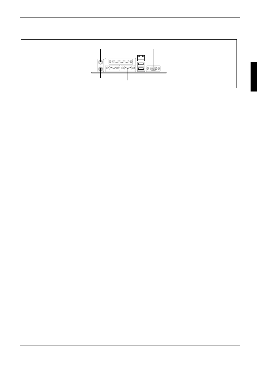
External ports
Features
1
8
1 = PS/2 mouse port
2 = Parallel port LPT
3 = LAN connector
4 = VGA port
2
67
4
3
5
5 = USB ports
6 = Serial port COM2
7 = Serial port COM1
8 = PS/2 keyboard port
Temperature / System monitoring
Temperature and system monitoring aim to reliably protect the computer hardware against damage
caused by overheating. In addi tion, any unnecessary nois e i s also prevented by reducing the f an
speed, and information is prov i ded about the system status. Cover monitoring protects the system
from unauthorised opening.
The temperature and system monitoring are controlled by an onboard controller developed by
Fujitsu Siemens.
The following functions are s upported:
Temperature monitoring:
Measurement of the processor temperature, measurement of the system temperature with an
onboard temperature sensor, measurem ent of the ambient temperature with an temperature sensor.
Fan monitoring:
Fans that are no longer available, blocked or sticky fans are detected. Blocked or sticky fans are
operated with 12 V pulse voltage. Fans removed while the system is switched off are signaled by
the Display ne ws LED when the system is switched on again and processed by the BIOS or the
application.
Fan control:
The fans are regulated according to temperature.
Sensor monitoring:
The removal of, or a fault in, a temperature sensor is detect ed. Should this happen all fans
monitored by this sens or run at m aximum speed, to achieve the greatest possible protection of the
hardware. Temperature sensors removed while the system is switched off are signaled by the
Display news LE D and processed by the BIOS or the appli cation.
Cover monitoring:
Unauthorised opening of the cover is detected, even when the system is switched off. However, this
will only be indicated when the system is switched on again.
A26361-D1309-Z120-1-7419 English - 5
Page 14
Features
LAN connector
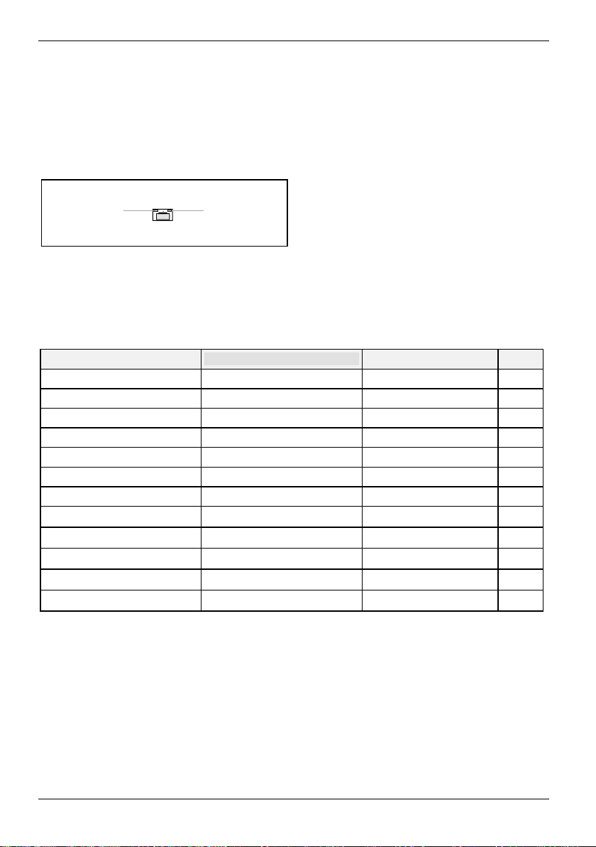
This system board has an Intel 82559 LAN controller. The LAN cont rol l er i s equipped with a 3 KB
transmission and receiv i ng buffer (FIFO) and supports WOL functi on through Magic Packetä.
It is also possi bl e to boot a device without its own boot hard disk via LAN. Here Booti x LAN BootP
and Intel PXE are supported.
The LAN RJ45 connector is equipped wi t h a yellow and a green LED (light emitting di ode).
1 = Yellow indicator
12
Green a connection exists (e.g. to a hub).
Yellow Link Mode: the LAN connection is active.
WOL mode: a Magic Packet
2 = Green indicator
TM
is being received.
ISA bus resources
Device IRQ Address DMA
Keyboard 1
Serial port COM2 3 03F8, 02F8, 03E8, 02E8
Serial port COM1 4 03F8, 02F8, 03E8, 02E8
5
Floppy disk drive control l er 6 2
Parallel interface LPT1 7 0278, 0378, 03BC 0, 1, 3
Real-time clock (RTC) 8
free 9, 10, 11
Mouse controller 12
Numeric processor 13
IDE controller 14 1F0-1F7
free 15
"IRQ" = interrupt assigned as shipped
"Address" = this addres s can be used for your particular dev i ce
"Address" = this DMA can be used for your particular dev i ce
Default settings are s hown i n bol d pri nt.
6 - English A26361-D1309-Z120-1-7419
Page 15
Features
PCI bus resources
PCI slots
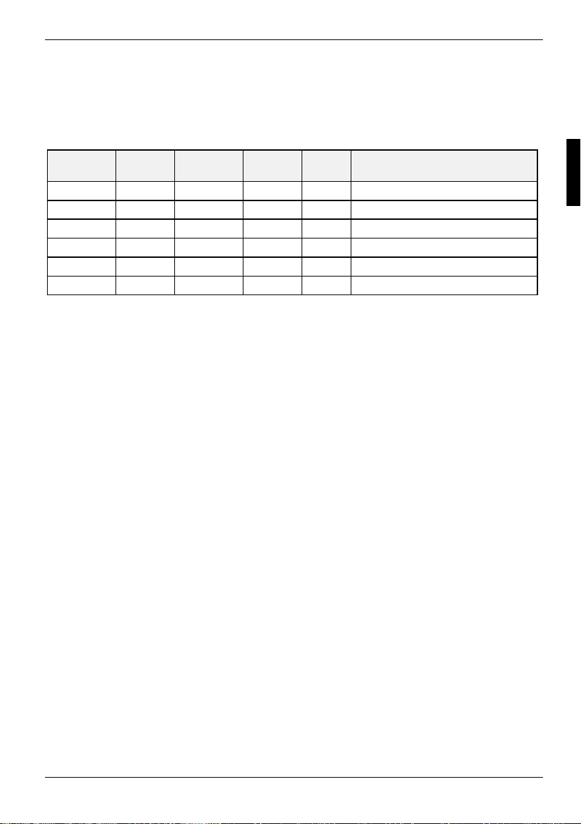
The following table shows an overv i ew of the PCI slots:
PCI slot 64bit/32bitFrequency
in MHz
1 32 bit 33 no no 32 bit PCI bus slot
2 64 bit 66 no no 64 bit PCI bus slot
3 64 bit 66 no no 64 bit PCI bus slot
4 64 bit 100 no yes 64 bit PCI bus s l ot
5 64 bit 100 no yes 64 bit PCI bus s l ot
6 32 bit 33 no no 32 bit PCI bus slot (short)
PCI IRQ line x - Assignment of the PCI interrupts
PCI IRQ Line x defines whi ch ISA interrupts are used f or the separate PCI slots.
If you select Auto in the BIOS setup, the interrupts are assigned automatically and no f urther
settings are required.
Multifunctional PCI boards or boards with an integrated PCI-t o-PCI bridge can use several PCI
interrupts (INTA#, INTB#, INTC#, INTD#). Monofunctional PCI boards (default) only use one PCI
interrupt (INTA#) per PCI slot .
The PCI interrupts INTA#, INTB #, INTC# and INTD# are available for every PCI s l ot .
The same interrupt can be assigned simultaneously to sev eral PCI boards. You should avoid thi s
condition due to reduced performance.
If you use a setting ot her than Auto, the Plug&Play functionality of the system BIOS for the
corresponding PCI boards is deac tivated.
Auto The PCI interrupts are assigned aut om atically in accordance with the Plug&Play
guidelines.
Disabled No ISA interrupt is assigned to the PCI interrupt.
3, 4, 5, 7, 10, 11, 12, 14, 15
The selected ISA interrupt i s assigned to the PCI interrupt. You may not select an
ISA interrupt that is used by a component on the system board (e.g. controll er) or an
ISA board.
Hot plug PCIX Description
A26361-D1309-Z120-1-7419 English - 7
Page 16
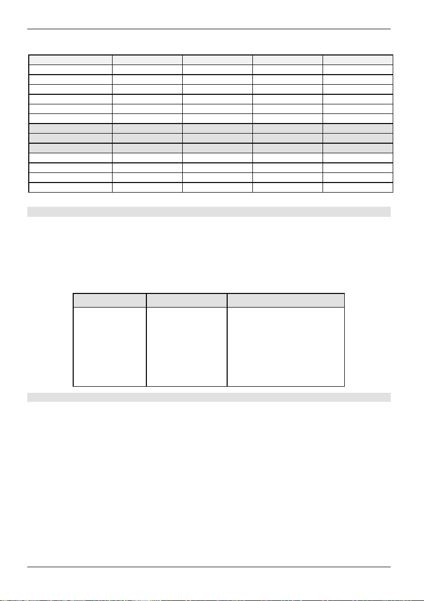
Features
Slot 1 PCI IRQ line 0 PCI IRQ line 1 PCI IRQ line 2 PCI IRQ line 3
Slot 2 PCI IRQ line 4 PCI IRQ line 5 PCI IRQ line 6 PCI IRQ line 7
Slot 3 PCI IRQ line 6 PCI IRQ line 7 PCI IRQ line 4 PCI IRQ line 5
Slot 4 PCI IRQ line 8 PCI IRQ line 9 PCI IRQ line 10 PCI IRQ line 11
Slot 5 PCI IRQ line 10 PCI IRQ line 11 PCI IRQ line 8 PCI IRQ line 9
Slot 6 PCI IRQ line 2 PCI IRQ line 3 PCI IRQ line 0 PCI IRQ line 1
Slot 7 PCI IRQ line 11 PCI IRQ line 8 PCI IRQ line 9 PCI I RQ l i ne 10
Slot 8 PCI IRQ line 8 PCI IRQ line 9 PCI IRQ line 10 PCI I RQ l i ne 11
Slot 9 PCI IRQ line 9 PCI IRQ line 10 PCI IRQ line 11 PCI IRQ line 8
VGA---SCSI PCI IRQ line 13 - - LAN PCI IRQ line 14 - - USB----
A..D = Interrupt output of the PCI controller
Slots 7 ... 9 are only available if a PCI expansion board is installed in slot 5.
A B C D
Screen resolution
Depending on the operating system used the screen resolutions in the following table refer to t he
screen controller on the system board. If y ou are using an external screen controller, you will f i nd
details of supported sc reen resolutions in the Operating Manual or Techni cal Manual supplied with
the controller.
Screen resolution Refresh rate (Hz) Max. number of col ours
640x480 200 16.7 mio.
800x600 200 16.7 mio.
1024x768 150 16.7 mio.
1052x864 120 16.7 mio.
1280x1024 100 16.7 mio.
1600x1200 76 16.7 mio.
Shaded screen resolutions are not s upport ed by LCD monitors (TFT).
8 - English A26361-D1309-Z120-1-7419
Page 17
Settings with switches
Settings with switches
ON
1
234 567
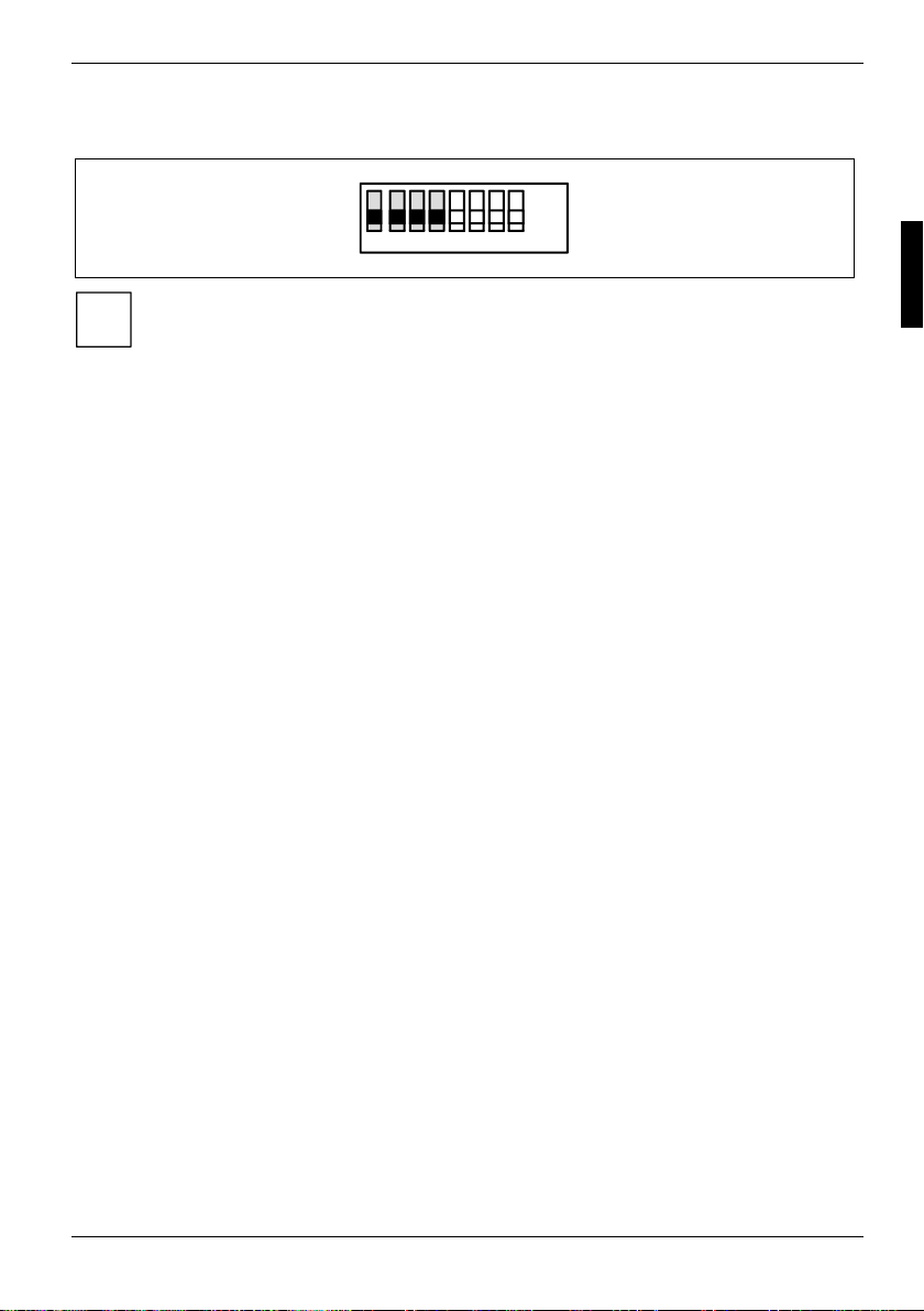
Preset for switches 1 t o 4 = Off.
i
The switches 5 to 8 don't hav e any function for the processor. The clock frequency of the
processor is set automatically. It c annot be changed manually.
Recovering System BIOS - switch 1
Switch 1 enables recovery of the old system BIOS after an attempt to update has failed. To restore
the old system BIOS you need a Flash BIOS Disk ette (please call our customer service centre).
on The system boots from the "Flash BIOS floppy di sk" from Drive A and reprograms
off The System BIOS is started with the system BIOS from the system board (default
the system BIOS on the board.
setting).
Skipping the password query - switch 2
Switch 2 is used to defi ne whether the password is queried at system startup, if the password
protection is enabled in BIOS Setup (in Security menu , t he Password field must be set to Enabled).
on The password query is effect i ve.
off The password query is skipped (default setting).
OFF
8
Write protection for Flash BIOS - switch 3
Switch 3 is used to defi ne whether the System BIOS i s write protected or not.
on The System BIOS can nei ther be written to nor deleted. Flash-BI OS update from
off The System BIOS can be written or deleted. Flas h-B IOS update from floppy disk i s
floppy disk is not possible.
possible (default setting).
Write protection for floppy disks - switch 4
Switch 4 is used to defi ne whether floppy disks can be written or deleted in the floppy disk drive. To
write and delete floppy disks, the write-protection in BIOS Setup must be disabled (in menu Security,
the field Diskette Write must be set to Enabled).
on The floppy disk drive is write-protected.
off Floppy disks can be read, written and deleted (default s etting).
A26361-D1309-Z120-1-7419 English - 9
Page 18
Add-on modules
Add-on modules
For all steps described in t hi s chapter pull the power plug out of the mai ns outlet!
!
9
8
7
6
5
4
3
PCI 6
PCI 5
PCI 4
PCI 3
PCI 2
PCI 1
12345678
Bank 2 – Module B
Bank 2 – Module A
Bank 1 – Module B
Bank 1 – Module A
Bank 0 – Module B
Bank 0 – Module A
CPU 0
CPU 1
1
2
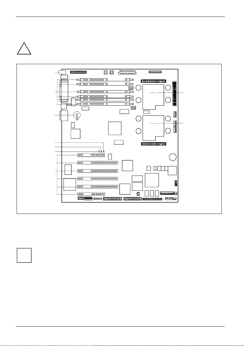
1 = Socket for processor 1 (CPU 0)
2 = Socket for processor 2 (CPU 1)
3 = PCI slots 1 to 6
4 = LED L1 (yellow): "System off“
5 = LED L2 (green): "System run“
PCI slots support 3.3 V main and auxiliary voltages.
i
6 = LED L3 (red): "Configuration error“
7 = Lithium battery
8 = Locations for main memory (mem ory bank
0-2)
9 = LED L4 (amber): "Message“
10 - English A26361-D1309-Z120-1-7419
Page 19

Add-on modules
Slot sequence
· An additional screen control l er m ust always be inserted into PCI slot 1 or 6.
· Insert 32 bit / 33 MHz adapter first into PCI slots 1, 6 and then into PCI slots 2, 3.
· Insert 64 bit / 33 MHz adapter first into PCI slots 2, 3 and then into PCI slots 4, 5.
· Insert 64 bit / 66 MHz adapter first into PCI slots 2, 3 and then into PCI slots 4, 5.
Upgrading main memory
These slots are suit abl e for DIMM format 512, 128, 256, 2048 and 1024 M B DDR SDRAM memory
modules. The organisation in three m emory banks 0 to 2 enables fast memory access with t wo-f ol d
interleave. The board supports a maximum of 12 Gbytes.
Two identical memory modules m ust be installed per memory bank . Partial equipping of a memory
bank is not possible. The equi ppi ng sequence of the memory banks is arbitrary.
You may only use regist ered DDR SDRAM memory modules. Unbuf f e red m em ory
modules are not permitted.
!
DDR SDRAM memory modules mu st be designed for a clock f requency of 100 MHz
(meets PC1600 specification).
A26361-D1309-Z120-1-7419 English - 11
Page 20
Add-on modules
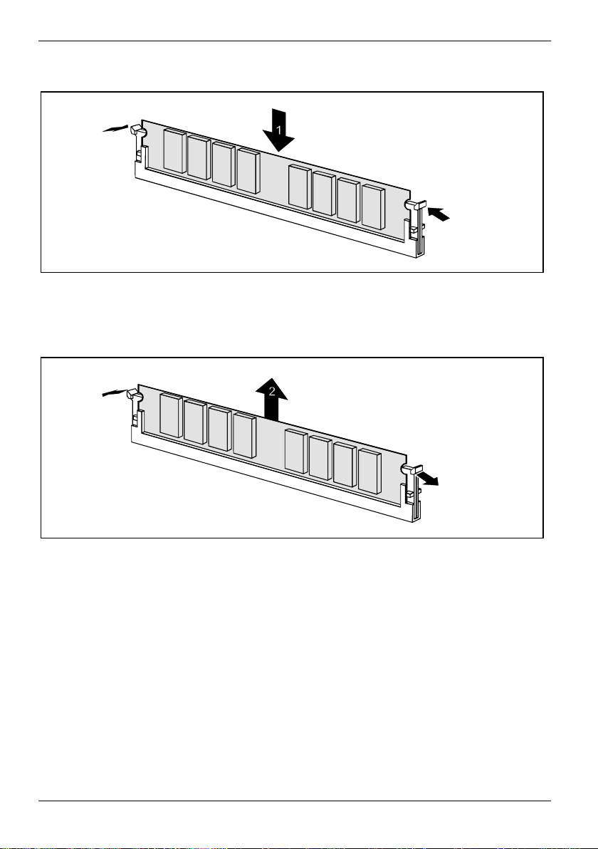
Installing a memory module
2
2
Ê Push the holders on each side of the memory compartment outwards.
Ê Insert the memory module in the slot while folding the side holders up until t he m em ory module
engages (2).
Removing a memory module
1
1
Ê Push the clips on the right and left of t he compartment outward (1).
Ê Carefully remove the memory module from the compartment (2).
12 - English A26361-D1309-Z120-1-7419
Page 21
Add-on modules
Replacing the lithium battery
Incorrect replacement of the lithium battery may l ead t o a ri sk of explosion.
!
The lithium battery must be replaced with an identical batt e ry or a battery type
recommended by the manufact urer (CR2032).
Do not throw lithium batteries into the household waste. They m ust be disposed of in
accordance with local regulations concerning special waste.
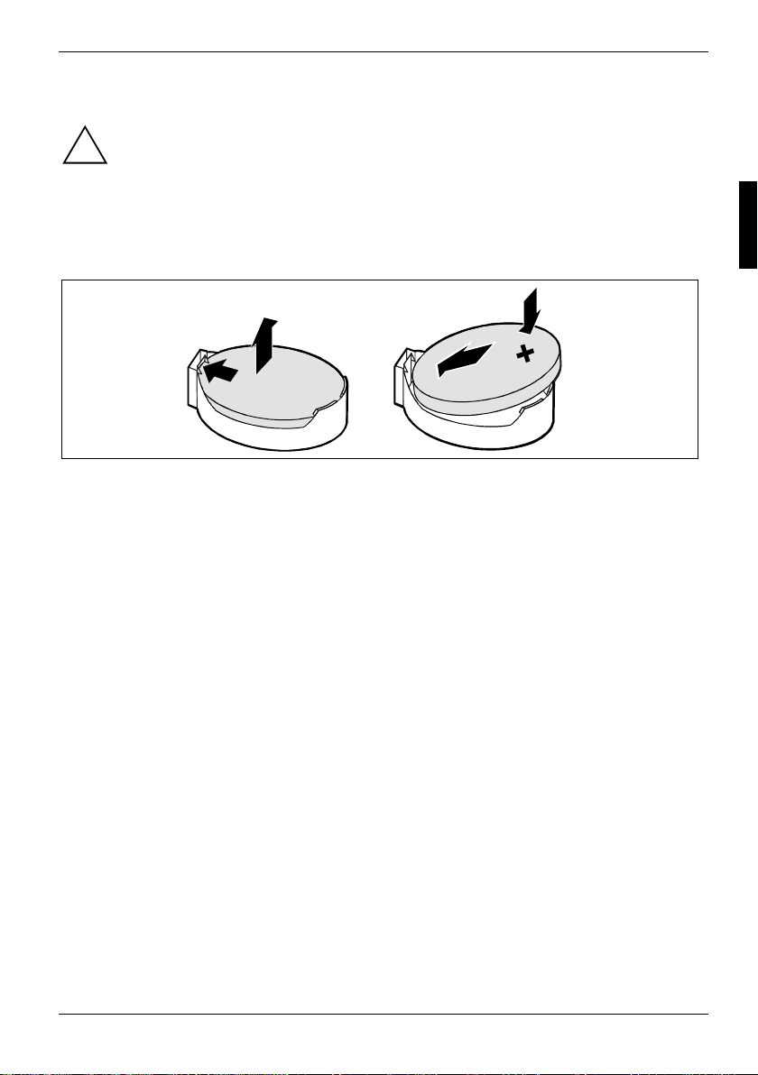
Ensure that you insert t he battery the right way round. The plus pol e m ust be on the top!
4
2
1
3
+
Ê Lift the contact (1) a few millimetres and remove the lithium bat tery from its socket (2).
Ê Insert a new lithium battery of the sam e type into the socket (3).
A26361-D1309-Z120-1-7419 English - 13
Page 22
Glossary
Glossary
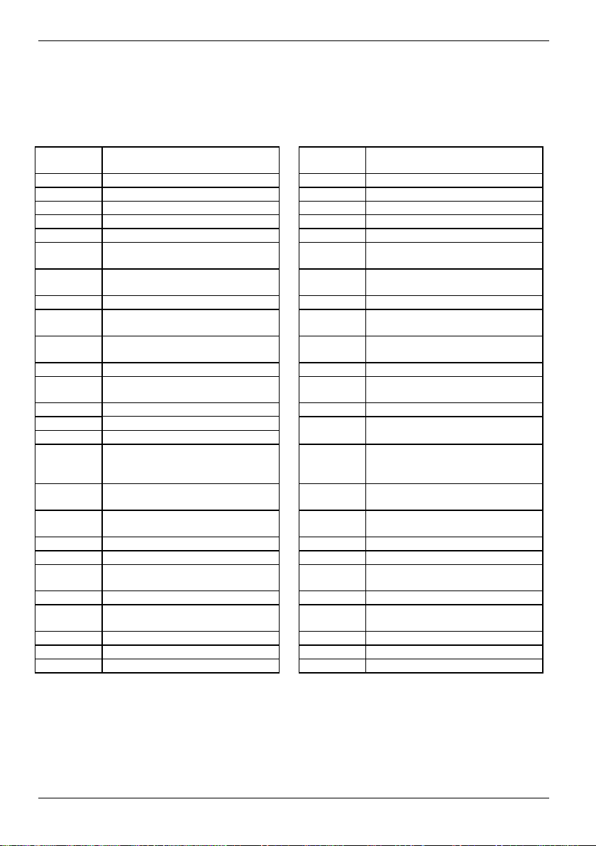
The technical terms and abbrevi ations given below represent only a s el ection of the full list of
common technical term s and abbreviations.
Not all technical terms and abbreviations listed here are valid for the described system board.
ACPI Advanced Configurati on and
Power Interface
AC'97 Audio Codec '97 LAN Local Area Network
AGP Accel erated Graphics Port LSA LAN Desk Service Agent
AIMM A G P Inline Memory Module MCH M emory Controller Hub
AMR Audio Modem Riser MMX MultiMedia eXtension
AOL Alert On LAN P64H PCI64 Hub
APM Advanced Power Management PCI Peripheral Component
ATA Advanced Technology
Attachment
BIOS Basic Input Output System RAM Random Access Memory
CAN Controller A rea Net work RAMDAC Random Access Memory Digital
CPU Central Proc essing Unit RDRAM Rambus Dynamic Random
CNR Communication Network Ris er RIMM Rambus Inline Memory Module
C-RIMM Continuity Rambus Inline
Memory Module
DIMM Dual Inline Memory Modul e RTC Real Time Clock
DDR Double Data Rate
ECC Error Correcti ng Code
EEPROM Electrical Erasable
Programmable Read Only
Memory
FDC Floppy Disk Controller SGRAM Sync hronous Graphic Random
FIFO First-In First-Out SIMD Streaming Mode Instruction
FSB Front Side Bus SMBus System Management Bus
FWH Firm ware Hub SVGA Super Video Graphic Adapter
GMCH Graphics and Memory Controller
Hub
I2C Inter I ntegrated Circuit VGA Video Graphic A dapter
IAPC Instantly A vailable Power
Managed Desktop PC Design
ICH I/O Controller Hub
IDE Intelligent Drive Elect roni cs
IPSEC Internet Protocol Security
ISA Industrial S tandard Architecture
Interconnect
PXE Preboot eXecution Environment
Analogue Converter
Access Memory
RSB Remote Service Board
SB Soundblaster
SDRAM Synchronous Dynamic Random
Access Memory
Access Memory
(Single Instruction Multiple Data)
USB Universal Serial Bus
WOL Wak e On LA N
14 - English A26361-D1309-Z120-1-7419
 Loading...