

Page 1
SYSTEM BOARD D1271 / D1291
SYSTEM BOARD D1271 / D1291SYSTEM BOARD D1271 / D1291
SYSTEM BOARD D1271 / D1291
TECHNICAL MANUAL
TECHNICAL MANUALTECHNICAL MANUAL
TECHNICAL MANUAL
Page 2

Are there ...
... any technical problems or other questions which you would like to be clarified?
Please contact:
• your salespartner
• your sales outlet
You will find further information in the manual "Safety, Warranty and
Ergonomics".
The latest information on our products, tips, updates, etc., can be found on the
Internet under:
http://www.fujitsu-siemens.com
Page 3

Page 4
Dieses Handbuch wurde auf Recycling-Papier gedruckt.
This manual has been printed on recycled paper.
Ce manuel est imprimé sur du papier recyclé.
Este manual ha sido impreso sobre papel reciclado.
Questo manuale è stato stampato su carta da riciclaggio.
Denna handbok är tryckt på recyclingpapper.
Dit handboek werd op recycling-papier gedrukt.
Herausgegeben von/Published by
Fujitsu Siemens Computers GmbH
Bestell-Nr./Order No.:
A26361-D1271-Z120-1-7619
A26361-D1271-Z120-1-7619A26361-D1271-Z120-1-7619
A26361-D1271-Z120-1-7619
Printed in the Federal Republic of Germany
AG 0101 01/01
A26361-D1271-Z120-1-7619
SYSTEM BOARD D1271 / D1291 TECHNICAL MANUAL
Page 5

SYSTEM BOARD
D1271 / D1291
Technical Manual
Introduction
Features
Hardware Setup
BIOS Setup
January 2001 edition
Page 6

Microsoft, MS, MS-DOS and Windows are registered trademarks of Microsoft Corporation.
VESA and DPMS are trademarks of Video Electronics Standards Association.
PS/2 and OS/2 Warp are registered trademarks of International Business Machines, Inc.
Copyright ã Fujitsu Siemens Computers GmbH 2001
All other trademarks referenced are trademarks or registered trademarks of their respective
owners, whose protected rights are acknowledged.
All rights, including rights of translation, reproduction by printing, copying or similar methods,
even of parts are reserved.
Offenders will be liable for damages.
All rights, including rights created by patent grant or registration of a utility model or design,
are reserved. Delivery subject to availability.
Right of technical modification reserved.
This manual was produced by
cognitas. Gesellschaft für Technik-Dokumentation mbH
www.cognitas.de
Page 7

D1271 / D1291 CUV-LSV / CUV-LV User's Manual 3
This manual describes server system board
D1271 - CUV-LSV
and
D1291 - CUV-LV.
Page 8

D1271 / D1291 CUV-LSV / CUV-LV User’s Manual
4
CONTENTS
1. INTRODUCTION ............................................................................. 7
1.1 How This Manual Is Organized ................................................... 7
1.2 Item Checklist .............................................................................. 7
2. FEATURES ........................................................................................ 8
2.1 CUV-LSV/LV Motherboard......................................................... 8
2.1.1 Specifications ..................................................................... 8
2.1.2 Special Features................................................................ 10
2.1.3 Performance Features ....................................................... 10
2.1.4 Intelligence ....................................................................... 11
2.2 Motherboard Components.......................................................... 12
2.2.1 Component Locations....................................................... 13
3. HARDWARE SETUP ...................................................................... 14
3.1 Motherboard Layout .................................................................. 14
3.2 Layout Contents ......................................................................... 15
3.3 Hardware Setup Procedure......................................................... 16
3.4 Motherboard Settings ................................................................. 16
3.5 System Memory ......................................................................... 23
3.5.1 General DIMM Notes....................................................... 23
3.5.2 Memory Installation ......................................................... 24
3.6 Central Processing Unit (CPU) .................................................. 25
3.6.1 CPU Installation ............................................................... 26
3.7 Expansion Cards ........................................................................ 27
3.7.1 Installing an Expansion Card ........................................... 27
3.7.2 Assigning IRQs for Expansion Cards .............................. 28
3.8 Connectors ................................................................................ 29
3.8.1 External Connectors ......................................................... 29
3.8.2 Internal Connectors .......................................................... 32
3.9 Starting Up the First Time.......................................................... 40
Page 9

D1271/D1291 CUV-LSV/CUV-LV User’s Manual 5
CONTENTS
4. BIOS SETUP..................................................................................... 41
4.1 Managing and Updating Your BIOS .......................................... 41
4.1.1 Upon First Use of the Computer System.......................... 41
4.1.2 Updating BIOS Procedures .............................................. 43
4.2 BIOS Setup Program.................................................................. 45
4.2.1 BIOS Menu Bar................................................................ 46
4.2.2 Legend Bar ....................................................................... 46
4.3 Main Menu................................................................................. 48
4.3.1 Primary & Secondary Master/Slave ................................. 49
4.3.2 Keyboard Features............................................................ 52
4.4 Advanced Menu ......................................................................... 54
4.4.1 Chip Configuration........................................................... 56
4.4.2 I/O Device Configuration ................................................. 59
4.4.3 PCI Configuration ............................................................ 61
4.4.4 Shadow Configuration ...................................................... 64
4.5 Power Menu ............................................................................... 65
4.5.1 Power Up Control............................................................. 67
4.5.2 Hardware Monitor ............................................................ 68
4.6 Boot Menu ................................................................................. 69
4.7 Server Menu ............................................................................... 71
4.8 Exit Menu................................................................................... 73
Page 10

D1271 / D1291 CUV-LSV / CUV-LV User’s Manual
6
FCC & DOC COMPLIANCE
Federal Communications Commission Statement
This device complies with FCC Rules Part 15. Operation is subject to the following
two conditions:
• This device may not cause harmful interference, and
• This device must accept any interference received, including interference that
may cause undesired operation.
This equipment has been tested and found to comply with the limits for a Class B
digital device, pursuant to Part 15 of the FCC Rules. These limits are designed to
provide reasonable protection against harmful interference in a residential
installation. This equipment generates, uses and can radiate radio frequency energy
and, if not installed and used in accordance with manufacturer's instructions, may
cause harmful interference to radio communications. However, there is no guarantee
that interference will not occur in a particular installation. If this equipment does
cause harmful interference to radio or television reception, which can be determined
by turning the equipment off and on, the user is encouraged to try to correct the
interference by one or more of the following measures:
• Re-orient or relocate the receiving antenna.
• Increase the separation between the equipment and receiver.
• Connect the equipment to an outlet on a circuit different from that to which
the receiver is connected.
• Consult the dealer or an experienced radio/TV technician for help.
W ARNING! Any changes or modifications to this product not expressly approved
by the manufacturer could void any assurances of safety or performance and
could result in violation of Part 15 of the FCC Rules.
Reprinted from the Code of Federal Regulations #47, part 15.193, 1993. Washington DC: Office of the
Federal Register, National Archives and Records Administration, U.S. Government Printing Office.
Canadian Department of Communications Statement
This digital apparatus does not exceed the Class B limits for radio noise emissions
from digital apparatus set out in the Radio Interference Regulations of the Canadian
Department of Communications.
This Class B digital apparatus complies with Canadian ICES-003.
Cet appareil numérique de la classe B est conforme à la norme NMB-003 du Canada.
Page 11

D1271/D1291 CUV-LSV/CUV-LV User’s Manual 7
1.1 How This Manual Is Organized
This manual is divided into the following sections:
1. INTRODUCTION Manual information and checklist
2. FEATURES Production information and specifications
3. HARDWARE SETUP Instructions on setting up the motherboard.
4. BIOS SETUP Instructions on setting up the BIOS
5. SOFTWARE SETUP Instructions on setting up the included software
6. SOFTWARE REFERENCE Reference material for the included software
7. APPENDIX Optional items and general reference
1.2 Item Checklist
Check that your package is complete. If you discover damaged or missing items,
contact your retailer.
1. INTRODUCTION
1. INTRODUCTION
Manual / Checklist
Package Contents
(1) Motherboard
(1) 40-pin 80-conductor ribbon
cable for internal UltraDMA/
66 or UltraDMA/33 IDE
drives
(1) Ribbon cable for two 3.5”
floppy disk drives
(1) Bag of spare jumper caps
(1) Support CD with
drivers and utilities
(1) User’s Manual
Optional Items
IrDA-compliant infrared
module
PCI-L101 Wake-On-LAN
10/100 Ethernet Card
2-port USB Connector Set
Page 12

8
D1271 / D1291 CUV-LSV / CUV-LV User’s Manual
2.1 CUV-LSV/LV Motherboard
The CUV-LSV motherboard is targeted diversely for home PCs and entrylevel workstations and servers. Powered by Intel
®
Pentium® III and Celeron™
processors, the CUV-LSV efficiently complies with today’s demand for a flexible
yet affordable system.
2.1.1 Specifications
• Latest Processor Support
Intel Pentium
®
III 133MHz FSB Coppermine core FC-PGA
Intel Pentium® III 100MHz FSB Coppermine core FC-PGA
Intel Celeron™ 66MHz FSB Mendocino core PPGA
• North Bridge System Chipset: Features the VIA VT82C694X system controller
that supports AGP 2X mode, 133/100/66MHz Front Side Bus (FSB), and
133/100/66MHz memory bus.
• South Bridge System Chipset: VIA VT82C686A PCIset with PCI Super I/O
integrated peripheral controller supports UltraDMA/66 for burst mode data transfer
rates of up to 66.6MB/sec and four USB ports.
• PC133 SDRAM / VC133 VCM / HSDRAM Support: Equipped with four Dual
Inline Memory Module (DIMM) sockets to support Intel PC133/PC100-compliant
(16, 32, 64, 128, 256, or 512MB), NEC’s VC133-compliant V irtual Channel (VC)
SDRAM, or Enhanced Memory System’s High-speed DRAMs (HSDRAMs) up
to 1GB. VC SDRAM and HSDRAM are new DRAM core architectures that
dramatically improves the memory system’s ability to service high multimedia
requirements.
• JumperFree™ Mode: Allows processor settings and easy overclocking of
frequency and Vcore voltage all through BIOS setup when the JumperFree™
mode is enabled. Easy-to-use DIP switches instead of jumpers are included to
allow manual adjustment of the processor external/internal frequency.
• Ultra SCSI Support: Equipped with the LSI 53C1010-33 Ultra160/Ultra3 64-bit
33MHz dual-channel SCSI controller that supports up to 30 SCSI devices. BIOS
configurable onboard SCSI settings.
• UltraDMA/66 Support: Comes with an onboard PCI Bus Master IDE controller
with two connectors that support four IDE devices on two channels. Supports
UltraDMA/66, UltraDMA/33, PIO Modes 3 & 4, and Enhanced IDE devices,
such as DVD-ROM, CD-ROM, CD-R/RW, LS-120, and Tape Backup drives.
• LAN Support: Features the Intel 82559 Fast-Ethernet LAN controller that fully
supports 10BASE-T/100BASE-TX.
• Wake-On-LAN Connector: Supports Wake-On-LAN activity through an
optional PCI-L101 10/100 Fast Ethernet PCI card.
2. FEATURES
Specifications
2. FEATURES
Page 13

D1271/D1291 CUV-LSV/CUV-LV User’s Manual 9
2. FEATURES
2. FEATURES
Specifications
• Wake-On-Ring Connector: Supports Wake-On-Ring activity through a PCI
modem card through a WOR connector.
• PC Health Monitoring: Provides an easy way to examine and manage system
status information, such as CPU and system voltages, temperatures, and fan
status through the onboard hardware ASIC and the bundled PC
Probe.
• SMBus: Features the System Management Bus interface used to physically
transport commands and information between SMBus devices.
• PCI Expansion Slots: Provides four 32-bit PCI (Rev. 2.2) expansion slots that
support Bus Master PCI cards, such as SCSI or LAN cards, with 133MB/s
maximum throughput.
• Super Multi-I/O: Provides two high-speed UART compatible serial ports and
one parallel port with EPP and ECP capabilities. UART2 can also be directed
from COM2 to the Infrared Module for wireless connections.
• Smart BIOS: 4MB firmware provides Vcore and CPU/SDRAM frequency
adjustments, boot block write protection, and HD/SCSI/MO/ZIP/CD/Floppy boot
selection.
• Enhanced ACPI and Anti-Boot Virus Pr otection: Programmable BIOS (Flash
EEPROM), offering enhanced ACPI for Windows 98 compatibility, built-in
firmware-based virus protection, and autodetection of most devices for a virtual
automatic setup.
• IrDA: Supports an optional infrared port module for wireless interface.
• Desktop Management Interface (DMI): Supports DMI through BIOS, which
allows hardware to communicate within a standard protocol creating a higher
level of compatibility. (Requires DMI-enabled components.)
• Onboard LED: Comes with a power LEDthat lights up if there is any standby
power on the motherboard. This LED acts as a reminder to turn off the system
power before plugging or unplugging devices to prevent damage to the
motherboard, peripherals, and other system components.
Page 14

10
D1271 / D1291 CUV-LSV / CUV-LV User’s Manual
2. FEATURES
Features
2. FEATURES
2.1.2 Special Features
• ACPI Support: Advanced Configuration Power Interface (ACPI) provides more
Energy Saving Features for operating systems that support OS Direct Power
Management (OSPM) functionality . W ith these features implemented in the OS,
PCs can be ready around the clock, yet satisfy all the energy saving standards.
To fully utilize the benefits of ACPI, an ACPI-supported OS, such as Windows
98 must be used.
• Easy Installation: Incorporates BIOS that supports autodetection of hard disk
drives, PS/2 mouse, and Plug and Play devices to make the setup of hard disk
drives, expansion cards, and other devices virtually automatic.
• PC’99 Compliant: Both the BIOS and hardware levels of smart series
motherboards are PC’99 compliant. The new PC’99 requirements for systems
and components are based on the following high-level goals: Support for Plugn-Play compatibility and power management for configuring and managing all
system components, and 32-bit device drivers and installation procedures for
Windows 95/98/NT. Color-coded connectors and descriptive icons make
identification easy as required by PC’99.
2.1.3 Performance Features
• Concurrent PCI: Concurrent PCI allows multiple PCI transfers from PCI master
busses to the memory and processor.
• High-Speed Data Transfer Interface: IDE transfers using UltraDMA/33 Bus
Master IDE can handle rates up to 33MB/s. This motherboard with its chipset
and support for UltraDMA/66 doubles the UltraDMA/33 burst transfer rate to
66.6MB/s. UltraDMA/66 is backward compatible with both DMA/33 and with
existing DMA devices so there is no need to upgrade current EIDE/IDE drives.
(UltraDMA/66 requires a 40-pin 80-conductor cable).
• VCM/SDRAM Optimized Performance: This motherboard supports the new
generation memory , NEC 64Mb Virtual Channel Memory (VCM) Synchronous
Dynamic Random Access Memory (SDRAM), that is compatible to the industry
standard SDRAM. The VCM’s core design provides up to 50% higher SDRAM
speed at reduced power consumption of about 30%. This motherboard also
supports the standard SDRAM for a the data transfer rate of up to 1.064GB/s using
PC133-compliant SDRAMs and up to 800MB/s using PC100-compliant
SDRAMs).
Page 15

D1271/D1291 CUV-LSV/CUV-LV User’s Manual 11
2. FEATURES
2. FEATURES
Intelligence
2.1.4 Intelligence
• Auto Fan Off: The system fans powers off automatically even in sleep mode.
This function reduces both energy consumption and system noise, and is an
important feature in implementing silent PC systems.
• Dual Function Power Button: Pushing the power button for less than 4 seconds
when the system is in the working state places the system into one of two states:
sleep mode or soft-off mode, depending on the BIOS or OS setting (see PWR
Button < 4 Secs in 4.5 Power Menu). When the power button is pressed for
more than 4 seconds, the system enters the soft-off mode regardless of the BIOS
setting.
• Fan Status Monitoring and Alarm: To prevent system overheat and system
damage, the CPU and system fans can be monitored for RPM and failure. All
fans are set for its normal RPM range and alarm thresholds.
• Power LED (requir es ACPI OS support): The power LED indicates the system
status.
• Remote Ring On (requires modem): This allows a computer to be turned on
remotely through an internal or external modem. With this benefit on-hand, users
can access vital information from their computers anywhere.
• System Resources Alert: Today’s operating systems such as Windows 95/98/
NT and OS/2, require much more memory and hard drive space to present
enormous user interfaces and run large applications. The system resource monitor
warns the user before the system resources are used up to prevent possible
application crashes. Suggestions provide the user some information on managing
their limited resources more efficiently.
• Temperature Monitoring and Alert: CPU temperature is monitored by the
ASIC through the CPU’s internal thermal diode (on Pentium III and
Celeron) to prevent system overheat and system damage.
• Voltage Monitoring and Alert: System voltage levels are monitored to ensure
stable voltage to critical motherboard components. Voltage specifications are
more critical for future processors, so monitoring is necessary to ensure proper
system configuration and management.
Page 16

12
D1271 / D1291 CUV-LSV / CUV-LV User’s Manual
2. FEATURES
2. FEATURES
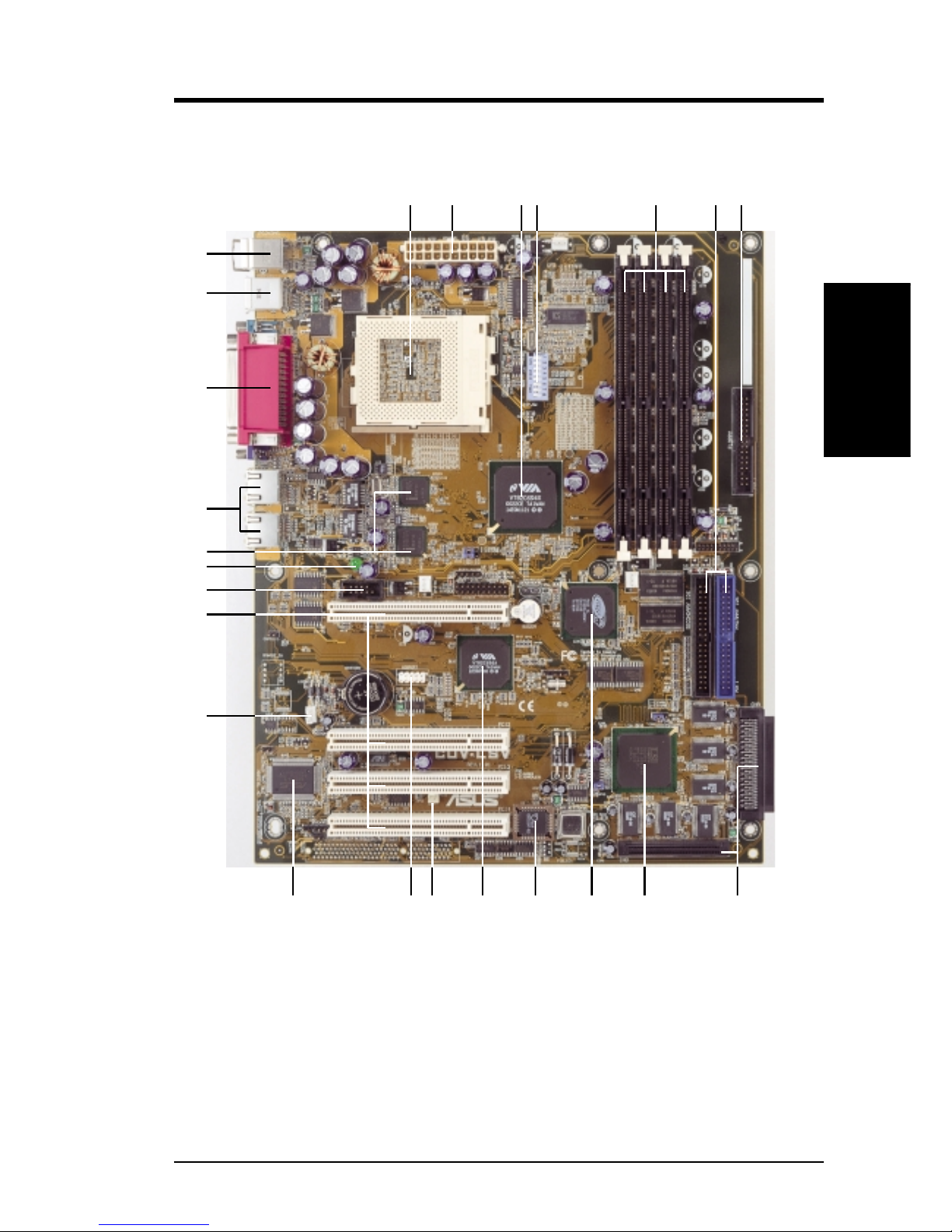
Motherboard Parts
Location
Processor Support Socket 370 for Pentium III/Celeron Processors ....................... 1
Feature Setting DIP Switches ................................................... 4
Chipsets VIA VT82C694X System Controller ........................................ 3
VIA VT82C686A PCIset......................................................... 12
ATI Rage XL Video Chipset ................................................... 10
4Mbit Programmable Flash EEPROM ................................... 11
Main Memory Maximum 2GB support
4 DIMM Sockets ...................................................................... 5
PC133 SDRAM support
Expansion Slots 4 PCI Slots .............................................................................. 17
System I/O 1 Floppy Disk Drive Connector ............................................... 7
2 IDE Connectors (UltraDMA/66 Support) ............................. 6
1 Parallel Port ............................................................... (Top) 22
1 Serial Port (COM1) ............................................. (Bottom) 22
1 Serial Port (COM2) ............................................................. 18
1 VGA Port ............................................................. (Bottom) 22
USB Connectors (Port 0 & Port 1) ........................................ 23
USB Connectors (Port 2 & Port 3) ......................................... 14
1 PS/2 Mouse Connector .............................................. (Top) 24
1 PS/2 Keyboard Connector ................................... (Bottom) 24
Network Features Intel 82559 Fast Ethernet Controllers .................................... 20
2 RJ-45 Connectors ................................................................ 21
Wake-On-LAN Connector...................................................... 16
Wake-On-Ring Connector ...................................................... 13
Hardware Monitoring System Voltage Monitoring (integrated in ASIC) ................. 15
2 Fan Power and Speed Monitoring Connectors
Power ATX Power Supply Connector ................................................. 2
Special Features LSI 32-bit Ultra160 SCSI Controller (optional)....................... 9
Onboard SCSI Connectors (optional)....................................... 8
Onboard LED ......................................................................... 19
Form Factor ATX
2.2 Motherboard Components
See opposite page for locations.
Page 17
D1271/D1291 CUV-LSV/CUV-LV User’s Manual 13
2. FEATURES
2. FEATURES
Motherboard Parts
2.2.1 Component Locations
17
24
22
21
23
2
19
5
101115
16
1
89
20
13
18
7643
1214
Page 18
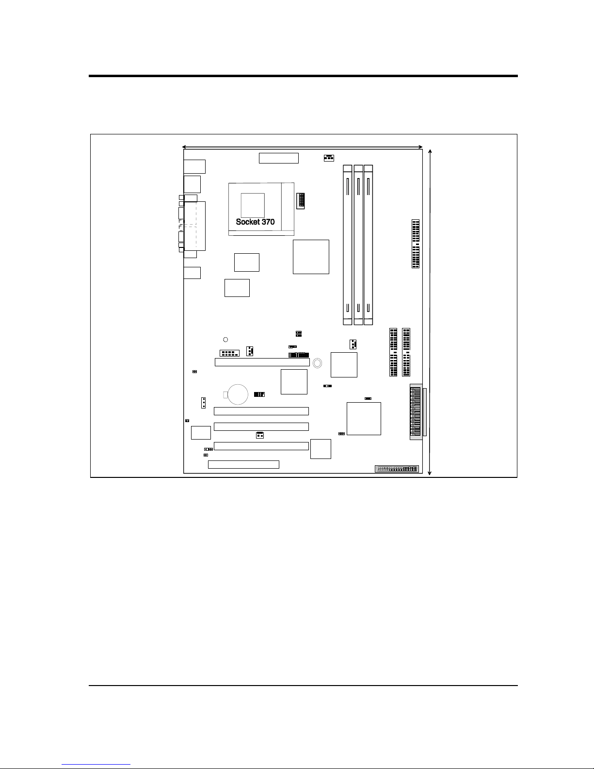
3 HARDWARE SETUP
3.1 Motherboard Layout
PS/2
T: Mouse
B: Keyboard
USB1
USB2
COM1
VGA
PARALLEL PORT
ATX_POW ER
PWRFAN
CPU_FAN
4Mbit
Firmware
Hub
(FWH)
WOR
ASIC
withHardware
Monitor
CR20323 V
Lithium Cell
CMOS Power
68-Pin Ultra 160/
Ultra3-Wide SCSI
Connector
PANEL
WOL_CON
PrimaryIDE
34
68
1
35
68-Pin Ultra 160/Ultra3-Wide
SCSI Connector
Fast
Ethernet
Controller
PCI 1
FLOPPY
IDE1
LSI SCSI
Controller
896/1010-33
VIA
VT82C694X
Chipset
DIMM Socket 1 (64/72-bit, 168-pin module01DIMM Socket 2 (64/72-bit, 168-pin module23DIMM Socket 3 (64/72-bit, 168-pin module
45
4
321
ON
8
765
Fast
Ethernet
Controller
DIP Switches
LAN1_EN
LAN2_EN
IR
VIA
VT82C686A
Chipset
BUZZER
CHAFAN
ATI
RAGE XL
VGA
Controller
COM2
SecondaryIDE
SMB
PCI 2
PCI 3
PCI 4
ASMC Slot
IDELED
BP_SMB
JTPWR
USBPORT
JEN
SCSI_EN
CHA
CHB
RJ-45
LED
CHASSIS
24.5cm (9.64in)
30.5cm (12.0in)
NOTE: The LSI SCSI controller chipset and SCSI channels (CHA and CHB) are
optional components.
14 D1271 / D1291 CUV-LSV / CUV-LV User’s Manual
Page 19

D1271/D1291 CUV-LSV/CUV-LV User’s Manual 15
3. HARDWARE SETUP
3.2 Layout Contents
Motherboard Settings
1) JEN p. 17 JumperFree Mode Setting (Disable/Enable)
2) DIP_SW 5–8 p. 18 CPU External Frequency Selection
3) DIP_SW 1-4 p. 19 CPU Core:BUS Frequency Multiple Selection
4) R56 p. 21 Clear RTC RAM
5) LAN-EN p. 21 LAN Setting
6) SCSI_EN p. 22 SCSI Setting (optional)
Expansion Slots/Sockets
1) DIMM 1/2/3/4 p. 24 DIMM Support
2) Socket 370 p. 25 CPU Support
3) PCI 1/2/3/4 p. 27 32-bit PCI Bus Expansion Slots
Connectors
1) PS2KBMS p. 29 PS/2 Mouse Port (6 pin-female)
2) PS2KBMS p. 29 PS/2 Keyboard Port (6-pin female)
3) USB p. 30 Universal Serial Bus Ports1 & 2 ( Two 4-pin female)
4) PRINTER p. 30 Parallel Port (25-pin female)
5) COM1/COM2 p. 30 Serial Ports (9-pin /10-1 pin male)
6) VGA p. 31 Monitor Output Port (15-pin female)
7) RJ-45 p. 31 Fast Ethernet LAN Connectors (Two RJ-45)
8) HDLED p. 32 IDE and SCSI Activity LED (2-pin)
9) FLOPPY p. 32 Floppy Disk Drive Port Connector (34 pins)
10) PRIMAR Y IDE p. 33 IDE Connectors (T wo 40-1 pins)
SECONDARY IDE
11) CHA/CHB p. 34 Ultra160 Wide SCSI Connectors (Two 68-pin)
12) WOL_CON p. 35 Wake-On-LAN Connector (3-pin)
13) WOR p. 35 Wake-On-Ring Connector (2-pin)
14) PWR/CP U /CHA_FAN p. 36 Power, CPU, and Chassis Fan Connectors (Three 3-pin)
15) USBPORT p. 36 USB2 Header (10-1 pins)
16) IR p. 37 Infrared Module Connector (5-pin)
17) CHASSIS p. 37 Chassis Intrusion Lead (2-pin)
18) ATXPWR p. 38 ATX Power Supply Connector (20 pins)
19) SMB/BP_SMB p. 38 SMBus Connectors (Two 5-1 pins)
20)
PWR.LED (
PANEL
)
p. 39 System Power LED Lead (3-pin)
21) SPEAKER (PANEL) p. 39 System Warning Speaker Connector (4-pin)
22) MSG.LED (PANEL) p. 39 System Message LED (2-pin)
23) SMI (PANEL) p. 39 System Management Interrupt Lead (2- pin)
24) PWR.SW (PANEL) p. 39 ATX / Soft-Off Switch Lead (2-pin)
25) RESET (PANEL) p. 39 Reset Switch Lead (2-pin)
Layout Contents
3. H/W SETUP
Page 20
16
D1271 / D1291 CUV-LSV / CUV-LV User’s Manual
3. HARDWARE SETUP
Motherboard Settings
3. H/W SETUP
3.3 Hardware Setup Procedure
Before using your computer, you must complete the following steps:
1. Check motherboard settings
2. Install memory modules
3. Install the Central Processing Unit (CPU)
4. Install Expansion Cards
5. Connect Ribbon Cables, Panel Wires, and Power Supply
6. Setup the BIOS Software
3.4 Motherboard Settings
This section explains how to change your motherboard function settings through the
switches and/or jumpers.
W ARNING! Computer motherboards and expansion cards contain very delicate
Integrated Circuit (IC) chips. T o protect them against damage from static electricity ,
you should follow some precautions whenever you work on your computer .
1. Unplug your computer when working on the inside.
2. Use a grounded wrist strap before handling computer components. If you do
not have one, touch both of your hands to a safely grounded object or to a
metal object, such as the power supply case.
3. Hold components by the edges and try not to touch the IC chips, leads or
connectors, or other components.
4. Place components on a grounded antistatic pad or on the bag that came with
the component whenever the components are separated from the system.
5. Ensure that the ATX power supply is switched off before you plug in or
remove the ATX power connector on the motherboard.
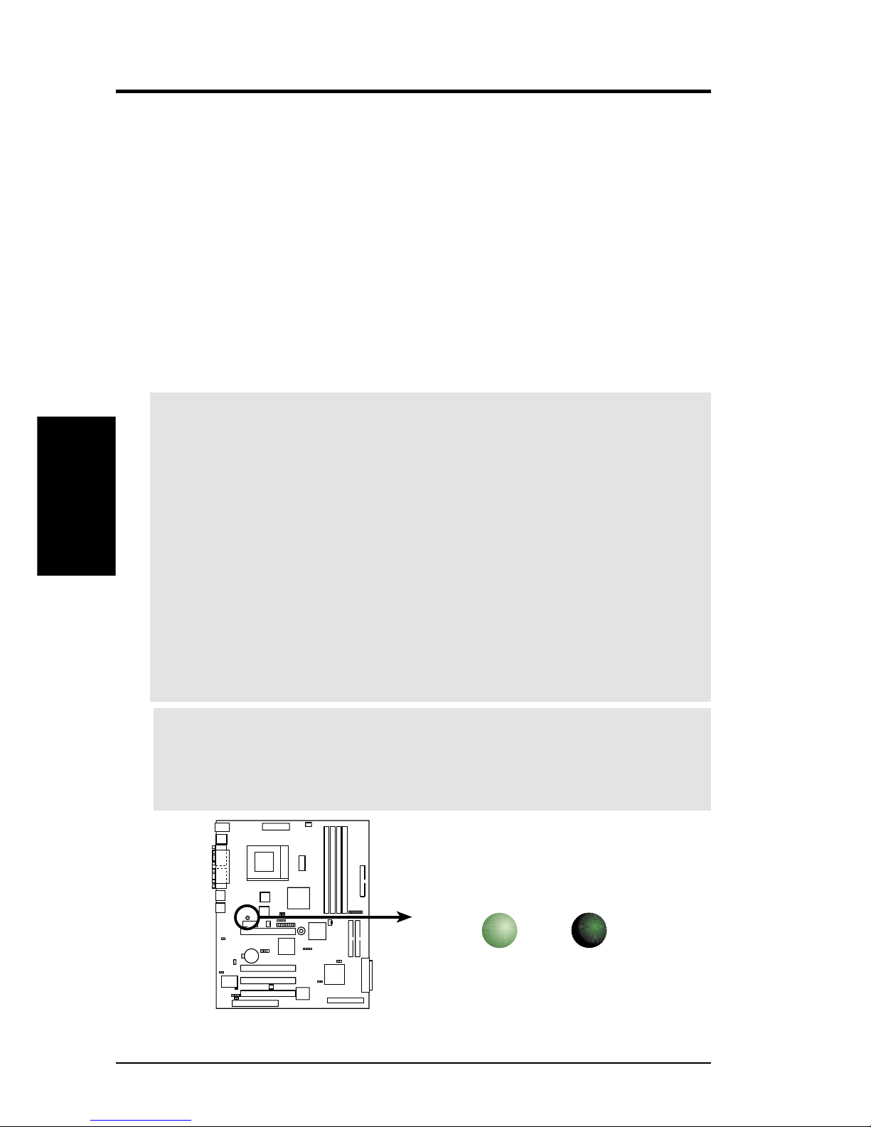
WARNING! Make sure that you unplug the power supply when adding or
removing system components. Failure to do so may cause severe damage to the
motherboard, peripherals, and/or components. When lit, the onboard LED
indicates that the system is in suspend or soft-off mode, not powered OFF.
CUV-LSV
CUV-LSV Onboard LED
ON
OFF
Standby
Power
Powered
Off
LED1
Page 21
D1271/D1291 CUV-LSV/CUV-LV User’s Manual 17
3. HARDWARE SETUP
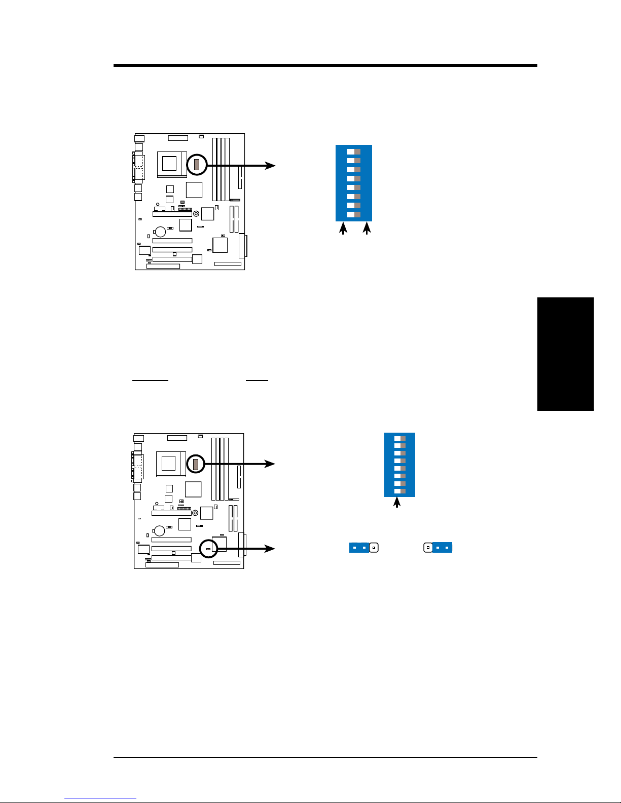
Motherboard Frequency Settings (DIP Switches - DIP_SW)
The motherboard frequency is adjusted through the DIP switches. The white block
represents the switch’s position. The example below shows all the switches in the
OFF position.
1) JumperFree™ Mode (JEN)
This jumper allows you to enable or disable the JumperFree™ mode. The
JumperFree™ mode allows processor settings to be made through the BIOS
setup (see 4.4 Advanced Menu).
Setting JEN
Enable (JumperFree) [2-3] (default)
Disable (Jumper) [1-2]
NOTE: In JumperFree™ mode, set all DIP switches (DIP_SW) to OFF.
3. H/W SETUP
Motherboard Settings
CUV-LSV DIP Switches
ON
12345678
OFF
ON
< Frequency Multiple
< Frequency Multiple
< Frequency Multiple
< Frequency Multiple
< Frequency Selection
< Frequency Selection
< Frequency Selection
< Frequency Selection
CUV-LSV
CUV-LSV
CUV-LSV JumperFree™ Mode Setting
Jumper Mode JumperFree Mode
(Default)
JEN
ON
12345678
OFF
DIP_SW
2
3
1
2
Page 22
18
D1271 / D1291 CUV-LSV / CUV-LV User’s Manual
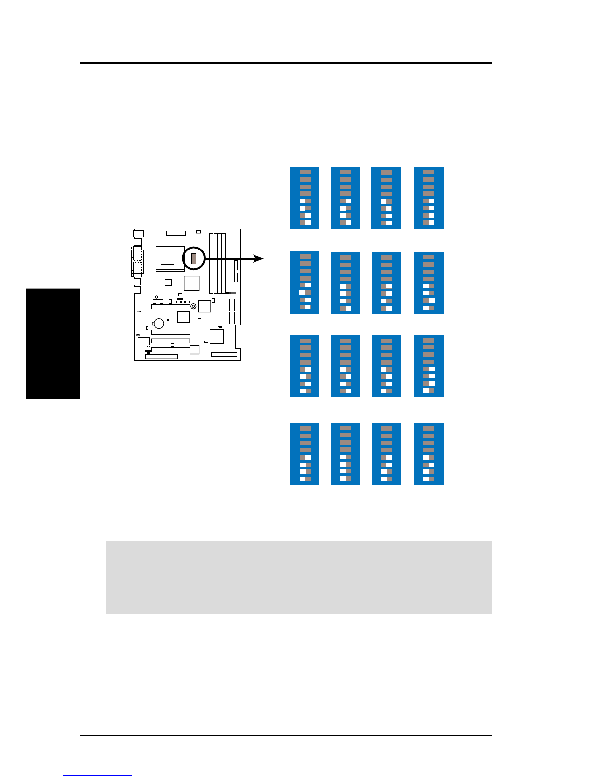
3) CPU External Frequency Selection (DIP_SW Switches 5–8)
This option tells the clock generator what frequency to send to the CPU, DRAM,
and the PCI bus. This allows the selection of the CPU’s External frequency (or
BUS Clock). The BUS Clock multiplied by the Frequency Multiple equals the
CPU’s Internal frequency (the advertised CPU speed).
3. HARDWARE SETUP
3. H/W SETUP
Motherboard Settings
CUV-LSV CPU External
Frequency Selection
83MHz
42MHz
ON
12345678
66MHz
33MHz
ON
12345678
68MHz
34MHz
ON
12345678
75MHz
37MHz
ON
12345678
80MHz
40MHz
ON
12345678
CPU
PCI
100MHz
33MHz
ON
12345678
CPU
PCI
103MHz
34MHz
ON
12345678
105MHz
35MHz
ON
12345678
110MHz
36MHz
ON
12345678
124MHz
31MHz
ON
12345678
CPU
PCI
CPU
PCI
150MHz
37MHz
ON
12345678
133MHz
33MHz
ON
12345678
140MHz
35MHz
ON
12345678
120MHz
40MHz
ON
12345678
115MHz
38MHz
ON
12345678
112MHz
37MHz
ON
12345678
CUV-LSV
WARNING! Set the CPUbus frequency to the recommended settings only.
Frequencies other than the recommended CPU bus frequencies are not guaranteed
stable. Overclocking the processor is not recommended. It may result in a slower
speed.
Page 23

D1271/D1291 CUV-LSV/CUV-LV User’s Manual 19
3. HARDWARE SETUP
3. H/W SETUP
Motherboard Settings
4) CPU Core:BUS Frequency Multiple (DIP_SW Switches 1–4)
This option sets the frequency multiple between the Internal frequency of the
CPU and the CPU’s External frequency. These must be set in conjunction with the
CPU Bus Frequency.
CUV-LSV CPU Core:Bus
Frequency Multiple
2.0x
ON
12345678
2.5x
ON
12345678
3.0x
ON
12345678
4.5x
ON
12345678
6.0x
ON
12345678
7.5x
ON
12345678
8.0x
ON
12345678
3.5x
ON
12345678
4.0x
ON
12345678
5.0x
ON
12345678
5.5x
ON
12345678
6.5x
ON
12345678
7.0x
ON
12345678
CUV-LSV
Page 24

20
D1271 / D1291 CUV-LSV / CUV-LV User’s Manual
3. HARDWARE SETUP
3. H/W SETUP
Motherboard Settings
Manual CPU Settings
NOTE: Disable the JumperFree™ mode when you are manually setting the
CPU frequency through the DIP switches.
Set the DIP switches b y the Internal speed of your processor as follows:
(CPU BUS Freq.) (Freq. Multiple)
Intel CPU Model
Freq. Mult. Bus F. 5 6 7 8 1 2 3 4
Pentium III 933MHz 7.0x 133MHz [OFF] [OFF] [OFF] [OFF] [ON] [OFF] [ON] [OFF]
Pentium III 866MHz 6.5x 133MHz [OFF] [OFF] [OFF] [OFF] [OFF] [ON] [ON] [OFF]
Pentium III 800MHz 6.0x 133MHz [OFF] [OFF] [OFF] [OFF] [ON] [ON] [ON] [OFF]
Pentium III 733MHz 5.5x 133MHz [OFF] [OFF] [OFF] [OFF] [OFF] [OFF] [OFF] [ON]
Pentium III 667MHz 5.0x 133MHz [OFF] [OFF] [OFF] [OFF] [ON] [OFF] [OFF] [ON]
Pentium III 600MHz 4.5x 133MHz [OFF] [OFF] [OFF] [OFF] [OFF] [ON] [OFF] [ON]
Pentium III 533MHz 4.0x 133MHz [OFF] [OFF] [OFF] [OFF] [ON] [ON] [OFF] [ON]
Pentium III 800MHz 8.0x 100MHz [OFF] [OFF] [OFF] [ON] [ON] [ON] [OFF] [OFF]
Pentium III 750MHz 7.5x 100MHz [OFF] [OFF] [OFF] [ON] [OFF] [OFF] [ON] [OFF]
Pentium III 700MHz 7.0x 100MHz [OFF] [OFF] [OFF] [ON] [ON] [OFF] [ON] [OFF]
Pentium III 650MHz 6.5x 100MHz [OFF] [OFF] [OFF] [ON] [OFF] [ON] [ON] [OFF]
Pentium III 600MHz 6.0x 100MHz [OFF] [OFF] [OFF] [ON] [ON] [ON] [ON] [OFF]
Pentium III 550MHz 5.5x 100MHz [OFF] [OFF] [OFF] [ON] [OFF] [OFF] [OFF] [ON]
Pentium III 500MHz 5.0x 100MHz [OFF] [OFF] [OFF] [ON] [ON] [OFF] [OFF] [ON]
Pentium III 450MHz 4.5x 100MHz [OFF] [OFF] [OFF] [ON] [OFF] [ON] [OFF] [ON]
Celeron 533MHz 8.0x 66MHz [OFF] [OFF] [ON] [ON] [ON] [ON] [OFF] [OFF]
Celeron 500MHz 7.5x 66MHz [OFF] [OFF] [ON] [ON] [OFF] [OFF] [ON] [OFF]
Celeron 466MHz 7.0x 66MHz [OFF] [OFF] [ON] [ON] [ON] [OFF] [ON] [OFF]
Celeron 433MHz 6.5x 66MHz [OFF] [OFF] [ON] [ON] [OFF] [ON] [ON] [OFF]
Celeron 400MHz 6.0x 66MHz [OFF] [OFF] [ON] [ON] [ON] [ON] [ON] [OFF]
Celeron 366MHz 5.5x 66MHz [OFF] [OFF] [ON] [ON] [OFF] [OFF] [OFF] [ON]
Celeron 333MHz 5.0x 66MHz [OFF] [OFF] [ON] [ON] [ON] [OFF] [OFF] [ON]
Celeron 300MHz 4.5x 66MHz [OFF] [OFF] [ON] [ON] [OFF] [ON] [OFF] [ON]
Celeron 266MHz 4.0x 66MHz [OFF] [OFF] [ON] [ON] [ON] [ON] [OFF] [ON]
IMPORTANT When using Celeron CPUs faster than 533MHz, select the
JumperFree™ mode to allow the system to autodetect the CPU and self-adjust to
the optimum frequency.
Page 25

D1271/D1291 CUV-LSV/CUV-LV User’s Manual 21
3. HARDWARE SETUP
Motherboard Settings
3. H/W SETUP
5) Clear RTC RAM
These two solder points allow you to clear the Real T ime Clock (RTC) RAM in
CMOS. You can clear the CMOS memory of date, time, and system setup
parameters by erasing the CMOS RTC RAM data. The RAM data in CMOS,
that include system setup information such as system passwords, is powered by
the onboard button cell battery.
T o erase the R TC RAM: (1) unplug the computer , (2) short the solder points, (3)
turn ON the computer, (4) hold down the <Del> key during the boot process and
enter BIOS setup to re-enter data.
6) LAN Setting Jumper (3-pin LAN_EN)
This jumper allows you to enable or disable the Local Area Network (LAN)
feature on the motherboard. The default setting is ENABLE.
CUV-LSV
CUV-LSV Clear RTC RAM
R56
Short solder points
to Clear CMOS
CUV-LSV
CUV-LSV LAN Setting
LAN_EN1
LAN_EN2
Enable Disable
12
2
3
Enable Disable
12
2
3
Page 26

22
D1271 / D1291 CUV-LSV / CUV-LV User’s Manual
7) SCSI Setting Jumper (3-pin SCSI_EN) (optional)
This jumper allows you to enable or disable the SCSI feature on the motherboard.
The default setting is ENABLE.
CUV-LSV
CUV-LSV SCSI Setting
Enable Disable
12
2
3
SCSI_EN
NOTE: This jumper is present on SCSI models only.
3. H/W SETUP
Motherboard Settings
Page 27

D1271/D1291 CUV-LSV/CUV-LV User’s Manual 23
3.5 System Memory
This motherboard uses only Dual Inline Memory Modules (DIMMs). Four DIMM
sockets are available for 3.3Volt (power level) unbuffered or registered Synchronous
Dynamic Random Access Memory (SDRAM) of 16, 32, 64, 128, 256, or 512 MB to
form a memory size between 32MB to 2GB. One side (with memory chips) of the
DIMM takes up one row on the motherboard. This motherboard also supports NEC’s
Virtual Channel SDRAMs and Enhanced Memory System’s High-speed DRAMs.
IMPORTANT (see General DIMM Notes below for more)
• SDRAMs used must be compatible with the current Intel PC133 SDRAM
specifications.
• DO NOT attempt to mix registered SDRAMs with VCM SDRAMs.
Install memory in any combination as follows:
DIMM Location 168-pin DIMM Total Memory
Socket 1 (Rows 0&1) SDRAM 16, 32, 64, 128, 256, 512MB x1
Socket 2 (Rows 2&3) SDRAM 16, 32, 64, 128, 256, 512MB x1
Socket 3 (Rows 4&5) SDRAM 16, 32, 64, 128, 256, 512MB x1
Socket 4 (Rows 6&7) SDRAM 16, 32, 64, 128, 256, 512MB x1
Total System Memory (Max. 2GB) =
3.5.1 General DIMM Notes
• DIMMs that have more than 18 chips are not supported on this motherboard.
• For the system CPU bus to operate 100MHz/133MHz, use only PC100-/PC133-
compliant DIMMs.
• Motherboards support Serial Presence Detect (SPD) DIMMs. This is the
memory of choice for best performance vs. stability.
• SDRAM chips are generally thinner with higher pin density than EDO (Extended
Data Output) chips.
• BIOS shows SDRAM memory on bootup screen.
• Single-sided DIMMs come in 16, 32, 64,128, 256MB; double-sided come in 32, 64,
128, 256, 512MB.
W ARNING! Make sure that the DIMM you use can handle the specified SDRAM
speeds, otherwise the computer does not boot.
System Memory
3. H/W SETUP
Page 28

24
D1271 / D1291 CUV-LSV / CUV-LV User’s Manual
3. HARDWARE SETUP
3. H/W SETUP
System Memory
3.5.2 Memory Installation
WARNING! Make sure that you unplug the power supply when adding or
removing memory modules or other system components. Failure to do so may
cause severe damage to both the motherboard and expansion cards (see 3.3
Hardware Setup Procedure for more information).
Insert the module(s) into the DIMM sockets as shown. Because the number of pins
are different on either side of the breaks, the module only fits in one direction. SDRAM
DIMMs have different pin contacts on each side and have a higher pin density than
DRAM SIMMs.
The DIMMs must be 3.3Volt unbuffered SDRAMs. To determine the DIMM type,
check the notches on the DIMMs (see the figure below).
The notches on the DIMM shifts between left, center, or right to identify the type
and also to prevent the wrong type from being inserted into the DIMM slot on the
motherboard. You must tell your retailer the correct DIMM type before purchasing.
This motherboard supports four clock signals per DIMM.
CUV-LSV
CUV-LSV 168-Pin DIMM Sockets
Lock
20 Pins
60 Pins
88 Pins
Page 29
D1271/D1291 CUV-LSV/CUV-LV User’s Manual 25
3. HARDWARE SETUP
CPU
3. H/W SETUP
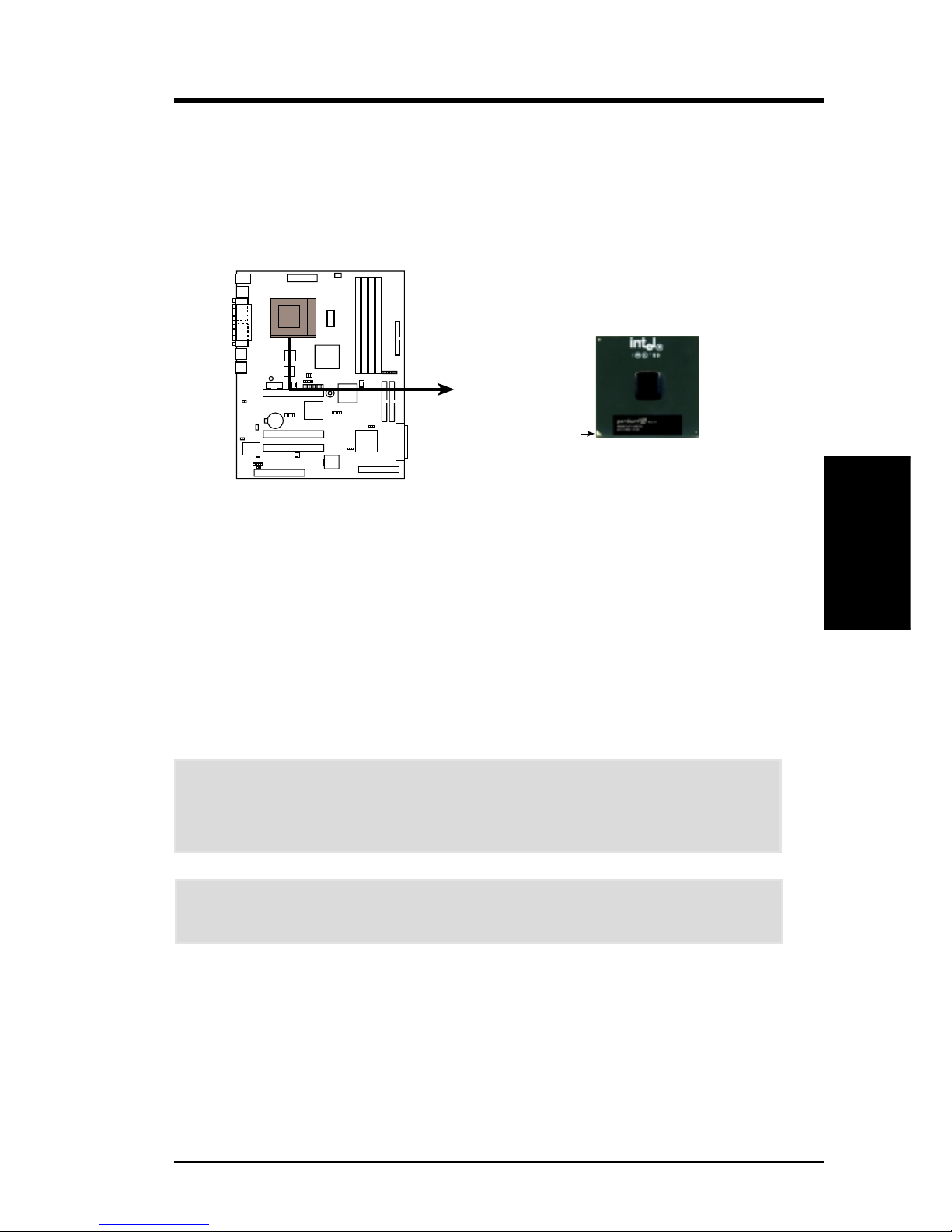
3.6 Central Processing Unit (CPU)
The motherboard comes with a ZIF Socket for the supported CPUs listed in section
2.1.1 Specifications. The following illustration shows the CPU socket location on
the motherboard and the correct CPU orientation.
Note in the illustration that CPUs have marks (usually a notch or a gold mark on one
corner) to help you identify the proper orientation and enable you to correctly install
a CPU. It is important that you match the marked corner of the CPU with the
corresponding corner on the socket so as not to damage the CPU pins.
The CPU picture above is for reference only. Usually, when you buy a CPU, the
heatsink and fan are already attached to the CPU. If a heatsink and fan did not come
with the package, make sure you obtain one before installing the CPU.
Proceed to the next section for the steps on how to properly install a CPU.
CAUTION! Be careful not to scrape the motherboard when mounting/unmounting
a clamp-style processor fan to avoid damaging the motherboard.
WARNING! You must install the proper heatsink and fan to the CPU. Failure to
do so will cause the CPU to overheat and may damage both the CPU and the
motherboard. Install an auxillary fan, if necessary.
CUV-LSV
CUV-LSV Socket 370
Gold Arrow
Pentium III
Page 30

26
D1271 / D1291 CUV-LSV / CUV-LV User’s Manual
3. HARDWARE SETUP
CPU Installation
3. H/W SETUP
3.6.1 CPU Installation
Follow these steps to install a CPU.
1. Locate the ZIF socket on the
motherboard.
2. Unlock the socket by pressing the
lever sideways then lifting it up to a
90°-100° angle.
5. Secure the CPU into the socket by pushing the socket lever all the way down.
You will hear a click indicating that the lever is in place.
6. Attach the heatsink and fan to the CPU, if they were not pre-installed by the
vendor . Refer to the installation instructions that came with the heatsink and fan.
CAUTION! The CPU fits only in one orientation. Do not force the CPU into the
socket to prevent bending the pins and damaging the CPU. If the CPU does not
fit completely, check its orientation or check for bent pins.
NOTE: Do not forget to set the correct Bus Frequency and Multiple (frequency
multiple setting is available only on unlocked processors) for the processor to avoid
start-up problems.
3. Position the CPU above the socket
such that its notched or marked
corner matches the socket corner
near the end of the lever, while
making sure that the CPU is parallel
to the socket.
4. Carefuly insert the CPU into the
socket until it fits in place.
Marked Corner
Page 31

D1271/D1291 CUV-LSV/CUV-LV User’s Manual 27
3. HARDWARE SETUP
Expansion Cards
3. H/W SETUP
3.7 Expansion Cards
In the future, you may need to install expansion cards. The motherboard has four
PCI expansion slots to support these cards. Follow the steps in the next section
when installing expansion cards.
W ARNING! Unplug the system power cord when adding or removing expansion
cards or other system components. Failure to do so may cause severe damage to
both the motherboard and expansion cards.
3.7.1 Installing an Expansion Card
1. Read the documentation that comes with the expansion card and make any
necessary hardware settings for the card before installing it.
2. Remove the system unit cover and the bracket plate on the slot you intend to use.
Keep the screw for later use.
3. Align the card connectors with the slot and press firmly until the card fits in
place.
4. Secure the card to the slot with the screw you removed earlier.
5. Replace the system cover.
6. Change the necessary BIOS settings, if any.
(see section 4.4.3 PCI Configuration to change the settings.)
7. Install the necessary software drivers for the expansion card.
Page 32

28
D1271 / D1291 CUV-LSV / CUV-LV User’s Manual
3. HARDWARE SETUP
Expansion Cards
3. H/W SETUP
3.7.2 Assigning IRQs for Expansion Cards
Some expansion cards need an IRQ to operate. Generally , an IRQ must be exclusively
assigned to one use. In a standard design, there are 16 IRQs available but most of
them are already in use, leaving 6 IRQs free for expansion cards.
IMPORTANT: If using PCI cards on shared slots, make sure that the drivers support
“Share IRQ” or that the cards do not need IRQ assignments. Conflicts arise between
the two PCI groups that will make the system unstable or cards inoperable.
The following table lists the default IRQ assignments for standard PC devices. Use
this table when configuring your system and for resolving IRQ conflicts.
Standard Interrupt Assignments
IRQ Priority Standard Function
0 1 System Timer
1 2 Keyboard Controller
2 N/A Programmable Interrupt
3* 11 Communications Port (COM2)
4* 12 Communications Port (COM1)
5* 13 Sound Card (sometimes LPT2)
6 14 Floppy Disk Controller
7* 15 Printer Port (LPT1)
8 3 System CMOS/Real Time Clock
9* 4 ACPI Mode when used
10* 5 IRQ Holder for PCI Steering
11* 6 IRQ Holder for PCI Steering
12* 7 PS/2 Compatible Mouse Port
13 8 Numeric Data Processor
14* 9 Primary IDE Channel
15* 10 Secondary IDE Channel
*These IRQs are usually available for ISA or PCI devices.
Interrupt Request Table for this Motherboard
INT-A INT-B INT-C INT-D
PCI slot 1 shared —— —
PCI slot 2 — shared ——
PCI slot 3 ——shared —
PCI slot 4 ———shared
Onboard AGP shared ———
Onboard LAN1 — shared ——
Onboard LAN2 ——shared —
Onboard SCSI CHA (optional) ———shared
Onboard SCSI CHB (optional) shared ———
Onboard USB Controller ———shared
Page 33

D1271/D1291 CUV-LSV/CUV-LV User’s Manual 29
3. HARDWARE SETUP
Connectors
3. H/W SETUP
3.8 Connectors
3.8.1 External Connectors
WARNING! Some pins are used for connectors or power sources. These are
clearly distinguished from jumpers in the Motherboard Layout. Placing jumper
caps over these connector pins will cause damage to your motherboard.
IMPORTANT: Ribbon cables should always be connected with the red stripe to
Pin 1 on the connectors. Pin 1 is usually on the side closest to the power connector
on hard drives and CD-ROM drives, but may be on the opposite side on floppy
disk drives. Check the connectors before installation because there may be
exceptions. IDE ribbon cable must be less than 46 cm (18 in.), with the second
drive connector no more than 15 cm (6 in.) from the first connector.
1) PS/2 Mouse Port (Green 6-pin PS2KBMS)
The system automatically directs IRQ12 to the PS/2 mouse if one is detected. If
no mouse is detected, IRQ12 become available to expansion cards. See PS/2
Mouse Function Control in 4.4 Advanced Menu.
2) PS/2 Keyboard Port (Purple 6-pin PS2KBMS)
This port is for a standard keyboard using an PS/2 plug (mini DIN). This
connector does not allow standard A T size (large DIN) keyboard plugs. You
may use a DIN to mini DIN adapter on standard AT keyboards.
PS/2 Mouse (6-pin female)
PS/2 Keyboard (6-pin female)
Page 34

30 D1271 / D1291 CUV-LSV / CUV-LV User’s Manual
3. HARDWARE SETUP
Connectors
3. H/W SETUP
3) Universal Serial Bus Ports 1 & 2 (Black two 4-pin USB)
Two USB ports are available for connecting USB devices.
5) Serial Ports (Teal/Turquoise 9-pin COM1)
One external serial port is ready for a mouse or other serial devices. A second
serial port is available using an optional serial port bracket. Connect the bracket
interface cable to the COM2 connector on the motherboard, then install the bracket
to an empty slot opening on the chassis. Make sure to enable the serial ports in
BIOS (see Onboard Serial Port 1 / Onboard Serial Port 2 in 4.4.2 I/O Device
Configuration for the settings).
4) Parallel Port (Burgundy 25-pin PRINTER)
You can enable the parallel port and choose the IRQ through Onboard Parallel
Port (see 4.4.2 I/O Device Configuration).
NOTE: Connect serial printers to the serial port.
Universal Serial Bus (USB) 2
USB 1
Parallel Port (25-pin female)
Serial Port (9-pin male) COM 1
Page 35

D1271/D1291 CUV-LSV/CUV-LV User’s Manual 31
3. HARDWARE SETUP
Connectors
3. H/W SETUP
7) Fast Ethernet LAN Connectors (RJ-45)
The RJ-45 connectors allow connection to a Local Area Network (LAN) through
a network hub.
6) Monitor Output Port (Blue 15-pin VGA)
The port is for a monitor or other VGA-compatible devices.
VGA Monitor (15-pin female)
RJ-45 Ports
Page 36

32 D1271 / D1291 CUV-LSV / CUV-LV User’s Manual
3. HARDWARE SETUP
Connectors
3. H/W SETUP
3.8.2 Internal Connectors
1) IDE and SCSI Activity LED (2-pin HDLED)
This connector supplies power to the IDE and SCSI activity LED on the chassis
front panel. Read and write activities by devices connected either to the IDE or
to the SCSI connectors cause the HDLED to light up.
2) Floppy Disk Drive Connector (34-1 pin FLOPPY)
This connector supports the provided floppy drive ribbon cable. After connecting
the single end to the board, connect the two plugs on the other end to the floppy
drives. (Pin 5 is r emoved to prevent inserting in the wr ong orientation when
using ribbon cables with pin 5 plugged).
CUV-LSV
NOTE: Orient the red markings on
the floppy ribbon cable to
PIN 1
CUV-LSV Floppy Disk Drive Connector
PIN 1
CUV-LSV IDE & SCSI Activity LED
TIP: If the case-mounted LED does not
light, try reversing the 2-pin plug.
HDLED
CUV-LSV
Page 37

D1271/D1291 CUV-LSV/CUV-LV User’s Manual 33
3. HARDWARE SETUP
Connectors
3. H/W SETUP
CUV-LSV
CUV-LSV IDE Connectors
NOTE: Orient the red markings
(usually zigzag) on the IDE
ribbon cable to PIN 1.
Secondary IDE Connector
Primary IDE Connector
PIN 1
3) Primary (Blue) / Secondary IDE Connectors (40-1 pin IDE1/IDE2)
These connectors support the provided UltraDMA/66 IDE hard disk ribbon
cable. Connect the cable’s blue connector to the primary (recommended) or
secondary IDE connector, then connect the gray connector to the UltraDMA/66
slave device (hard disk drive) and the black connector to the UltraDMA/66 master
device. It is recommended that non-UltraDMA/66 devices be connected to the
secondary IDE connector. If you install two hard disks, you must configure the
second drive as a slave device by setting its jumper accordingly. Refer to the
hard disk documentation for the jumper settings. BIOS supports specific device
bootup (see 4.6. Boot Menu). If you have more than two UltraDMA/66 devices,
purchase another UltraDMA/66 cable.
NOTES:
1. Pin 20 on each IDE connector is removed to match the covered hole on the
UltraDMA cable connector. This prevents incorrect orientation when you
connect the cables.
2. The hole near the blue connector on the UltraDMA/66 cable is intentional.
TIP: You may configure two hard disks to be both Masters with two ribbon
cables – one for the primary IDE connector and another for the secondary
IDE connector.
IMPORT ANT: For UltraDMA/66 IDE devices, use a 40-pin 80-conductor IDE cable.
Page 38

34 D1271 / D1291 CUV-LSV / CUV-LV User’s Manual
3. HARDWARE SETUP
Connectors
3. H/W SETUP
4) Two 68-pin Ultra160/Ultra3 SCSI Connectors (optional)
This motherboard has two 68-Pin Ultra160/Ultra3 SCSI connectors, one for each
of the two channels. Each channel can support a maximum of 15 devices as
specified by Ultra160/Ultra3 standards. (NOTE: The 68-pin Ultra160 SCSI
connectors are present on SCSI models only.)
SCSI Connection Notes
The onboard SCSI chipset incorporates an advanced multimode I/O cell that supports
both single-ended (SE), Ultra3, and Ultra160 devices. With Ultra160/Ultra3 devices,
the SCSI bus platform performs at full Ultra160/Ultra3 speeds (up to 160MB/sec)
and extended cabling 12m (or 25m in a point-to-point configuration). When an SE
device is attached, the bus defaults to an SE speed and 1.5m cable length.
IMPORTANT: Connect SCSI devices as shown. Each channel should have only
one type of SCSI standard (e.g. Ultra160, Ultra3, Ultra-Wide). Mixing SCSI devices
on the same channel decreases performance of the slower device.
NOTE: Ultra160/Ultra3 SCSI devices do not have termination jumpers and must
use a separate terminator on the last connector (internal) or device (external).
CUV-LSV
CUV-LSV
Onboard SCSI Connectors
3568
34 1
35
6834
1
CHB (Internal)
68-Pin Ultra160/Ultra2-Wide SCSI Connector
CHA (External)
68-Pin Ultra160/
Ultra2-Wide SCSI Connector
CUV-LSV
CUV-LSV SCSI Connection Example
68-pin Internal SCSI Cable (Twisted-Pair Ribbon)
68-pin Female
Terminator
Internal SCSI Devices (up to 15 devices)
Channel A
68-pin Internal SCSI Cable (Twisted-Pair Ribbon)
68-pin Female
Terminator
Internal SCSI Devices (up to 15 devices)
Channel B
Page 39

D1271/D1291 CUV-LSV/CUV-LV User’s Manual 35
3. HARDWARE SETUP
Connectors
3. H/W SETUP
5) Wake-On-LAN Connector (3-pin WOL_CON)
This connector connects to a LAN card with a Wake-On-LAN output, such as
the PCI-L101 Ethernet card (see 7. Appendix). The connector powers up
the system when a wakeup packet or signal is received through the LAN card.
IMPORTANT: This feature requires that Wake-On-LAN field in BIOS is
enabled (see 4.5.1 Power Up Control ) and that your system has an ATX power
supply with at least 720mA +5V standby power.
6) Wake-On-Ring Connector (2-pin WOR)
This connector connects to internal modem cards with a Wake-On-Ring output.
The connector powers up the system when a ringup packet or signal is received
through the internal modem card. NOTE: For external modems, W ake-On-Ring
is detected through the COM port.
CUV-LSV
CUV-LSV Wake-On-LAN Connector
IMPORTANT: Requires an ATX power
supply with at least 720mA +5 volt
standby power.
+5 Volt Standby
PME
Ground
WOL_CON
CUV-LSV
CUV-LSV Wake-On-Ring Connector
WOR
RI#
Ground
21
Page 40

36 D1271 / D1291 CUV-LSV / CUV-LV User’s Manual
3. HARDWARE SETUP
Connectors
3. H/W SETUP
7) Power Fan, CPU Fan, and Chassis Fan Connectors
The three fan connectors (PWR_F AN, CPU_FAN, CHA_FAN) support cooling
fans of 350mA (4.2 Watts) or less. Orient the fans so that the heat sink fins allow
airflow to go across the onboard heat sink(s) instead of the expansion slots. The
fan wiring and plug may vary depending on the fan manufacturer. The red wire
should be positive while the black should be ground. Connect the fan plug to the
board taking into consideration the polarity of the connector.
NOTE: Use th e “Rotation” signal only with a specially designed fan with a rotation
signal. You can monitor the Rotations P er Minute (RPM) of the fans using the
PC Probe (see 6. SOFTWARE REFERENCE).
WARNING! The CPU and/or motherboard will overheat if there is no airflow
across the CPU and onboard heatsinks. Damage may occur to the motherboard
and/or the CPU fan if these pins are incorrectly used. These are not jumpers,
do not place jumper caps over these pins.
8) USB Header (10-1 pin USBPORT)
If the USB port connectors on the back panel are inadequate, one USB header is
available for two additional USB port connectors. Connect the USB header to a
2-port USB connector set and mount the bracket to an open slot in the chassis.
(The USB connector set is optional and does not come with the motherboard
package.)
CUV-LSV
CUV-LSV 12-Volt Cooling Fans
PWRFAN
GND
Rotation
+12V
CPUFAN
GND
Rotation
+12V
CHAFAN
GND
Rotation
+12V
CUV-LSV Front Panel USB Header
USBPORT
USB Power
USBP2–
USBP2+
GND
NC
USB Power
USBP3–
USBP3+
GND
15
610
CUV-LSV
Page 41

D1271/D1291 CUV-LSV/CUV-LV User’s Manual 37
3. HARDWARE SETUP
Connectors
3. H/W SETUP
9) Standard Infrared Module Connector (5-pin IR)
This connector supports an optional wireless transmitting and receiving infrared
module. This module mounts to a small opening on system cases that support
this feature. You must also configure the setting through UART2 Use Infrared
(see 4.4.2 I/O Device Configuration) to select whether UART2 is directed for
use with COM2 or IrDA. Use the five pins as shown in Back View and connect
a ribbon cable from the module to the motherboard SIR connector according to
the pin definitions.
10) Chassis Intrusion Lead (2-pin CHASSIS)
This lead is for a chassis designed for chassis intrusion detection. This requires
an external detection mechanism such as a chassis intrusion monitor/sensor or
microswitch. When any chassis component is removed, the sensor is triggered
and a high-level signal is sent to this lead to record a chassis intrusion event.The
event is then be processed by software such as LDCM. When not using the
chassis intrusion lead, place a jumper cap over the pins to close the circuit.
CUV-LSV
CUV-LSV Infrared Module Connector
Front View Back View
+5V
IRTX
IRRX
(NC)
GND
+5V
IRRX
IRTX
(NC)
GND
IR
1
CUV-LSV Chassis Open Alarm Lead
CHASSIS
CUV-LSV
Page 42

38 D1271 / D1291 CUV-LSV / CUV-LV User’s Manual
3. HARDWARE SETUP
Connectors
3. H/W SETUP
11) Power Supply Connector (20-pin block ATXPWR)
This connector connects to an ATX 12V power supply. The plugs from the power
supply fits in only one orientation because of the different hole sizes. Find the
proper orientation and push down firmly making sure that the pins are aligned.
IMPORTANT: Make sure that the ATX 12V power supply (minimum
recommended wattage: 230W) can supply at least 100mA on the +5-volt standby
lead (+5VSB). The system may become unstable and may experience difficulty
powering up if the power supply is inadequate. For Wake-On-LAN support, the
ATX power supply must supply at least 720mA +5VSB.
12) SMBus Connectors (5-1 pin SMB, BP_SMB)
These connectors allow you to connect SMBus (System Management Bus)
devices. SMBus devices communicate by means of the SMBus with an SMBus
host and/or other SMBus devices. SMBus is a specific implementation of an I
2
C
bus, which is a multi-device bus. This means that multiple chips can be connected
to the same bus and each one can act as a master by initiating data transfer.
CUV-LSV ATX Power Connector
+3.3 Volts
-12.0 Volts
Ground
Power Supply On
Ground
Ground
Ground
-5.0 Volts
+5.0 Volts
+5.0 Volts
Power Good
+12.0 Volts
+3.3 Volts
+3.3 Volts
Ground
+5.0 Volts
Ground
+5.0 Volts
Ground
+5V Standby
CUV-LSV
CUV-LSV SMBus Connectors
BP_SMB
SMBCLK
Ground
SMBDATA
+5V
1
SMBCLK
Ground
SMBDATA
+5V
1
SMB
CUV-LSV
Page 43

D1271/D1291 CUV-LSV/CUV-LV User’s Manual 39
3. HARDWARE SETUP
Connectors
3. H/W SETUP
The following 20-pin PANEL illustration is for items 13-18.
13) System Power LED Connector(3-1 pin PWR.LED)
This 3-1 pin connector connects to the system power LED. The LED lights up
when you turn on the system power, and blinks when the system is in sleep or
soft-off mode.
14) System Warning Speaker Connector (4-pin SPEAKER)
This 4-pin connector connects to the case-mounted speaker.
15) System Message LED Connector (2-pin MSG.LED)
This 2-pin connector is for the system message LED that indicates receipt of
messages from a fax/modem. The normal status for this LED is ON, when there
is no incoming data signal. The LED blinks when there is data received. The
system message LED feature requires an ACPI OS and driver support.
16) System Management Interrupt Connector (2-pin SMI)
This 2-pin connector allows you to manually place the system into a suspend
mode, or “Green” mode, where system activity is instantly decreased to save
power and to expand the life of certain system components. Attach the casemounted suspend switch this 2-pin connector.
17) ATX Power Switch / Soft-Off Switch Connector (2-pin PWR.SW)
The system power is controlled by a momentary switch attached to this connector .
Pressing the button switches the system between ON and SLEEP, or ON and
SOFT OFF, depending on the BIOS or OS settings. Pressing the button while in
the ON mode for more than 4 seconds turns the system off.
18) Reset Switch Connector (2-pin RESET)
This 2-pin connector connects to the case-mounted reset switch for rebooting
the system without turning off the power switch. This is a preferred method
CUV-LSV
CUV-LSV System Panel Connectors
*
Requires an ATX power supply.
PLED
Ground
MLED
PWR_SW
+5 V
+5V
SPKR
Ground
+5 V
ExtSMI#
ResetCon
NC
NC
Reset SW
Power LED
ATX Power Switch*
Message LED
SMI Lead
Speaker
Connector
Ground
Page 44

40 D1271 / D1291 CUV-LSV / CUV-LV User’s Manual
3. HARDWARE SETUP
Connectors
3. H/W SETUP
3.9 Starting Up the First Time
1. After making all the connections, replace the system case cover.
2. Be sure that all switches are off (in some systems, marked with
).
3. Connect the power cord to the power connector at the back of the system chassis.
4. Connect the power cord to a power outlet that is equipped with a surge protector.
5. Turn on the devices in the following order:
a. Monitor
b. External SCSI devices (starting with the last device on the chain)
c. System power (For ATX power supplies, you need to switch on the power
supply as well as press the ATX power switch on the front of the chassis.)
6. The power LED on the front panel of the system case lights up. For ATX power
supplies, the system LED lights up when you press the ATX power switch. If the
monitor complies with “green” standards or if it has a power standby feature,the
monitor LED may light up or switch between orange and green after the system
LED does. The system then runs the power-on tests. While the tests are running,
the BIOS beeps or additional messages appear on the screen. If you do not see
anything within 30 seconds from the time you turn on the power, the system
may have failed a power-on test. Check the jumper settings and connections or
call your retailer for assistance.
Award BIOS Beep Codes
Beep Meaning
One short beep when No error during POST
displaying logo
Long beeps in an endless loop No DRAM installed or detected
One long beep followed by Video card not found or video card
three short beeps memory bad
High frequency beeps when CPU overheated
system is working System running at a lower frequency
7. At power on, hold down <Delete> to enter BIOS Setup. Follow the instructions
in 4. BIOS SETUP.
* Powering Off the computer: Y ou must first exit or shut down the system before
switching off the power switch. For ATX power supplies, you can press the ATX
power switch after exiting or shutting down the operating system. If you use
Windows 9X, click the Start button, click Shut Down, then click Shut down
the computer? The power supply should turn off after Windows shuts down.
NOTE: The message “You can now safely turn off your computer” does not
appear when shutting down with ATX power supplies.
Page 45

4. BIOS SETUP
D1271/D1291 CUV-LSV/CUV-LV User’s Manual 41
4.1 Managing and Updating Your BIOS
4.1.1 Upon First Use of the Computer System
It is recommended that you save a copy of the original motherboard BIOS along with a Flash
Memory Writer utility (AFLASH.EXE) to a bootable floppy disk in case you need to reinstall the BIOS
later. AFLASH.EXE is a Flash Memory Writer utility that updates the BIOS by uploading a new
BIOS file to the programmable flash ROM on the motherboard. This file works only in DOS mode.
To determine the BIOS version of your motherboard, check the last four numbers of the code
displayed on the upper left-hand corner of your screen during bootup. Larger numbers represent a
newer BIOS file.
1. Type FORMAT A:/S at the DOS prompt to create a bootable system floppy disk.DO NOT copy
AUTOEXEC.BAT and CONFIG.SYS to the disk.
2. Type COPY D:\AFLASH\AFLASH.EXE A:\ (assuming D is your CD-ROM drive) to copy
AFLASH.EXE to the just created boot disk.
NOTE: AFLASH works only in DOS mode. It will not work with DOS prompt in Windows and will not
work with certain memory drivers that may be loaded when you boot from your hard drive. It is
recommended that you reboot using a floppy.
3. Reboot your computer from the floppy disk.
NOTE: BIOS setup must specify “Floppy” as the first item in the boot sequence.
4. In DOS mode, type A:\AFLASH <Enter> to run AFLASH.
ASUS ACPI BIOS
FLASH MEMORY WRITER V1.24
Copyright (C) 1994-99, ASUSTeK COMPUTER INC.
Flash Memory: Winbond W29C020 or SST 29EE020 or Intel 82802AB
Current BIOS Version: ASUS XXX-XX ACPI BIOS Revision 100X
BIOS Model : XXX-XX
BIOS Built Date : 09/25/99
Choose one of the followings:
1. Save Current BIOS To File
2. Update BIOS Including Boot Block and ESCD
Enter Choice: [1]
Press ESC To Exit
IMPORTANT! If “unknown” is displayed after Flash Memory:, the memory chip is either not
programmable or is not supported by the ACPI BIOS and therefore, cannot be programmed by the
Flash Memory Writer utility.
Page 46

4. BIOS SETUP
42 D1271 / D1291 CUV-LSV / CUV-LV User’s Manual
5. Select 1. Save Current BIOS to File from the Main menu and press <Enter>. TheSave Current
BIOS To File screen appears.
Save Current BIOS To File
Flash Memory: Winbond W29C020 or SST 29EE020 or Intel 82802AB
Current BIOS Version: ASUS XXX-XX ACPI BIOS Revision 100X
BIOS Model : XXX-XX
BIOS Built Date : 09/25/99
Please Enter File Name to Save: XXX-XX.XXX
BIOS Saved Successfully
Press ESC To Exit
6. Type a filename and the path, for example,A:\XXX-XX.XXX and then press <Enter>.
Page 47

4. BIOS SETUP
D1271/D1291 CUV-LSV/CUV-LV User’s Manual 43
4.1.2 Updating BIOS Procedures
WARNING! Only update your BIOS if you have problems with your motherboard and you know that
the new BIOS revision will solve your problems. Careless updating can result in your motherboard
having more problems!
1. Download an updated BIOS file from the Internet (WWW or FTP) and save to the disk you
created earlier.
2. Boot from the disk you created earlier.
3. At the “A:\” prompt, type AFLASH and then press <Enter>.
4. At the Main Menu, type 2 and then press <Enter>. TheUpdate BIOS Including Boot Block and
ESCD screen appears.
5. Type the filename of your new BIOS and the path, for example,A:\XXX-XX.XXX, and then press
<Enter>.
NOTE: To cancel this operation, press <Enter>.
Update BIOS Including Boot Block and ESCD
Flash Memory: Winbond W29C020 or SST 29EE020 or Intel 82802AB
Current BIOS Version: ASUS XXX-XX ACPI BIOS Revision 100X
BIOS Model : XXX-XX
BIOS Built Date : 09/25/99
Please Enter File Name for NEW BIOS: A:\XXX-XX.XXX
6. When prompted to confirm the BIOS update, pressY to start the update.
Update BIOS Including Boot Block and ESCD
Flash Memory: Winbond W29C020 or SST 29EE020 or Intel 82802AB
BIOS Version
[Current ] ASUS XXX-XX ACPI BIOS Revision 100X
[test.awd] ASUS XXX-XX ACPI BIOS Revision 100X
BIOS Mode
[Current ] XXX-XX
[test.awd] XXX-XX
Date of BIOS Built
[Current ] 09/25/99
[test.awd] 05/29/00
Check sum of 1001.010 is F266.
Are you sure (Y/N) ? [Y]
Press ESC To Return to Main Menu
Page 48

4. BIOS SETUP
44 D1271 / D1291 CUV-LSV / CUV-LV User’s Manual
7. The utility starts to program the new BIOS information into the flash ROM. The boot block will be
updated automatically only when necessary. This will minimize the chance that a failed update will
prevent your system from booting up. When the programming is finished,Flashed Successfully will
be displayed.
Update BIOS Including Boot Block and ESCD
Flash Memory: Winbond W29C020 or SST 29EE020 or Intel 82802AB
BIOS Version
[Current ] ASUS XXX-XX ACPI BIOS Revision 100X
[test.awd] ASUS XXX-XX ACPI BIOS Revision 100X
BIOS Mode
[Current ] XXX-XX
[test.awd] XXX-XX
Date of BIOS Built
[Current ] 09/25/99
[test.awd] 05/29/00
Check sum of 1001.010 is F266.
Are you sure (Y/N) ? [Y]
Block Erasing –- Done
Programming -- 3FFFF
Flashed Successfully
Press ESC To Continue
8. Follow the onscreen instructions to continue.
ASUS ACPI BIOS
FLASH MEMORY WRITER V1.24
Copyright (C) 1994-99, ASUSTeK COMPUTER INC.
Flash Memory: Winbond W29C020 or SST 29EE020 or Intel 82802AB
Current BIOS Version: ASUS XXX-XX ACPI BIOS Revision 100X
BIOS Model : XXX-XX
BIOS Built Date : 09/25/99
Choose one of the followings:
1. Save Current BIOS To File
2. Update BIOS Including Boot Block and ESCD
Enter Choice: [1]
You have flashed the EPROM, It is recommended that you turn off
the power, enter SETUP and LOAD Setup defaults to have CMOS
updated with new BIOS when exits.
Press ESC To Exit
WARNING! If you encounter problems while updating the new BIOS, DO NOT turn off your system
since this might prevent your system from booting up. Just repeat the process, and if the problem
still persists, update the original BIOS file you saved to disk above. If the Flash Memory Writer utility
was not able to successfully update a complete BIOS file, your system may not be able to boot up.
If this happens, your system will need servicing.
Page 49

D1271/D1291 CUV-LSV/CUV-LV User’s Manual 45
4. BIOS SETUP
4. BIOS SETUP
4.2 BIOS Setup Program
This motherboard supports a programmable EEPROM that you can update using
the provided utility described in 4.1 Managing and Updating Your BIOS.
The utility is used if you are installing a motherboard, reconfiguring your system,
or prompted to “Run Setup”. This section describes how to configure your system
using this utility.
Even if you are not prompted to use the Setup program, at some time in the future
you may want to change the configuration of your computer. For example, you
may want to enable the Security Password Feature or make changes to the power
management settings. It will then be necessary to reconfigure your system using
the BIOS Setup program so that the computer can recognize these changes and
record them in the CMOS RAM of the EEPROM.
The EEPROM on the motherboard stores the Setup utility. When you start up the
computer, the system provides you with the opportunity to run this program. This
appears during the Power-On Self Test (POST). Press <Delete> to call up the Setup
utility . If you are a little bit late in pressing the mentioned key, POST will continue
with its test routines, thus preventing you from calling up Setup. If you still need to
call Setup, restart the system by pressing <Ctrl> + <Alt> + <Delete>, or by pressing
the Reset button on the system chassis. You can also restart by turning the system
off and then back on again. But do so only if the first two methods fail.
The Setup program has been designed to make it as easy to use as possible. It is a
menu-driven program, which means you can scroll through the various sub-menus
and make your selections among the predetermined choices.
To access the BIOS Setup program, press the <Delete> key after
the computer has run through its POST.
NOTE: Because the BIOS software is constantly being updated, the following
BIOS setup screens and descriptions are for reference purposes only, and may
not exactly match what you see on your screen.
Program Information
Page 50

D1271 / D1291 CUV-LSV / CUV-LV User’s Manual46
4. BIOS SETUP
4. BIOS SETUP
4.2.1 BIOS Menu Bar
The top of the screen has a menu bar with the following selections:
MAIN Use this menu to make changes to the basic system configuration.
ADVANCED Use this menu to enable and make changes to the advanced
features.
POWER Use this menu to configure and enable Power Management
features.
BOOT Use this menu to configure the default system device used to locate
and load the Operating System.
EXIT Use this menu to exit the current menu or specify how to exit the
Setup program.
To access the menu bar items, press the right or left arrow key on the keyboard
until the desired item is highlighted.
4.2.2 Legend Bar
At the bottom of the Setup screen is a legend bar. The keys in the legend bar allow
you to navigate through the various setup menus. The following table lists the keys
found in the legend bar with their corresponding functions.
Navigation Key(s) Function Description
<F1> or <Alt + H> Displays the General Help screen from anywhere in the BIOS
Setup
<Esc> Jumps to the Exit menu or returns to the main menu from a
sub-menu
← or → (keypad arrow) Selects the menu item to the left or right
↑ or ↓ (keypad arrow) Moves the highlight up or down between fields
- (minus key) Scrolls backward through the values for the highlighted field
+ (plus key) or spacebar Scrolls forward through the values for the highlighted field
<Enter> Brings up a selection menu for the highlighted field
<Home> or <PgUp> Moves the cursor to the first field
<End> or <PgDn> Moves the cursor to the last field
<F5> Resets the current screen to its Setup Defaults
<F10> Saves changes and exits Setup
Menu Introduction
Page 51

D1271/D1291 CUV-LSV/CUV-LV User’s Manual 47
4. BIOS SETUP
4. BIOS SETUP
General Help
In addition to the Item Specific Help window , the BIOS setup program also provides
a General Help screen. You may launch this screen from any menu by simply
pressing <F1> or the <Alt> + <H> combination. The General Help screen lists the
legend keys with their corresponding functions.
Saving Changes and Exiting the Setup Program
See 4.7 Exit Menu for detailed information on saving changes and exiting the
setup program.
Scroll Bar
When a scroll bar appears to the right of a help window, it indicates that there is
more information to be displayed that will not fit in the window. Use <PgUp> and
<PgDn> or the up and down arrow keys to scroll through the entire help document.
Press <Home> to display the first page, press <End> to go to the last page. To exit
the help window, press <Enter> or <Esc>.
Sub-Menu
Note that a right pointer symbol (as shown in the left view)
appears to the left of certain fields. This pointer indicates
that you can display a sub-menu from this field. A submenu contains additional options for a field parameter . To
display a sub-menu, move the highlight to the field and
press <Enter>. The sub-menu appears. Use the legend keys
to enter values and move from field to field within a submenu as you would within a menu. Use the <Esc> key to
return to the main menu.
T ake some time to familiarize yourself with the legend keys and their corresponding
functions. Practice navigating through the various menus and sub-menus. If you
accidentally make unwanted changes to any of the fields, use the set default hot
key <F5> to load the Setup default values. While moving around through the Setup
program, note that explanations appear in the Item Specific Help window located
to the right of each menu. This window displays the help text for the currently
highlighted field.
NOTE: The item heading in square brackets represents the default setting for
that field.
Menu Introduction
Page 52

D1271 / D1291 CUV-LSV / CUV-LV User’s Manual48
4. BIOS SETUP
4. BIOS SETUP
System Time [XX:XX:XX]
Sets the system to the time that you specify (usually the current time). The
format is hour, minute, second. Valid values for hour, minute and second
are Hour: (00 to 23), Minute: (00 to 59), Second: (00 to 59). Use the
<Tab> or <Shift> + <Tab> keys to move between the hour, minute, and
second fields.
System Date [XX/XX/XXXX]
Sets the system to the date that you specify (usually the current date). The
format is month, day , year . V alid values for month, day, and year are Month:
(1 to 12), Day: (1 to 31), Y ear: (100 year range). Use the <T ab> or <Shift>
+ <Tab> keys to move between the month, day, and year fields.
Legacy Diskette A [1.44M, 3.5 in.], Legacy Diskette B [None]
Sets the type of floppy drives installed. Configuration options: [None]
[360K, 5.25 in.] [1.2M , 5.25 in.] [720K , 3.5 in.] [1.44M, 3.5 in.]
[2.88M, 3.5 in.]
Floppy 3 Mode Support [Disabled]
This is required to support older Japanese floppy drives. The Floppy 3
Mode feature allows reading and writing of 1.2MB (as opposed to
1.44MB) on a 3.5-inch diskette. Configuration options: [Disabled]
[Enabled]
4.3 Main Menu
When you enter the Setup program, the following screen appears:
Main Menu
Page 53

D1271/D1291 CUV-LSV/CUV-LV User’s Manual 49
4. BIOS SETUP
4. BIOS SETUP
NOTE: Before attempting to configure a hard disk drive, make sure you
have the configuration information supplied by the drive manufacturer.
Incorrect settings may cause the system to fail to recognize the installed
hard disk. T o allow the BIOS to detect the drive type automatically , select
[Auto].
Type [Auto]
Select [Auto] to automatically detect an IDE hard disk drive. If automatic
detection is successful, Setup automatically fills in the correct values for
the remaining fields on this sub-menu. If automatic detection fails, this
may be because the hard disk drive is too old or too new. Try updating the
BIOS or manually entering the IDE hard disk drive parameters.
NOTE: After entering the IDE hard disk drive information into BIOS,
use a disk utility, such as FDISK, to partition and format new IDE hard
disk drives. This is necessary so that you can write or read data from the
hard disk. Make sure to set the partition of the Primary IDE hard disk
drives to active.
Other options for the Type field are:
[None] - to disable IDE devices
4.3.1 Primary & Secondary Master/Slave
Master/Slave Drives
Page 54

D1271 / D1291 CUV-LSV / CUV-LV User’s Manual50
4. BIOS SETUP
4. BIOS SETUP
IMPORT ANT: If the hard disk was already formatted on an older system,Setup may
detect incorrect parameters. You will need to enter the correct parameters manually,
or use low-level format in case you do not need the data stored on the hard disk. If the
parameters listed differ from the ones used when the disk was formatted, the disk
will not be readable. If the auto-detected parameters do not match the ones that
should be used for the disk, you should enter the correct ones manually by setting
[User Type HDD].
Master/Slave Drives
[User Type HDD]
Manually enter the number of cylinders, heads and sectors per track for the drive.
Refer to the drive documentation or on the drive label for this information. If no
drive is installed or if you are removing a drive and not replacing it, select [None].
Translation Method [LBA]
Select the hard disk drive type in this field. When Logical Block Addressing is
enabled, 28-bit addressing of the hard drive disregarding cylinders, heads, or sectors.
Note that LBA Mode is necessary for drives with more than 504MB storage capacity.
Configuration options: [LBA] [LARGE] [Normal] [Match Partition T able] [Manual]
Cylinders
This field configures the number of cylinders. Refer to the drive documentation to
determine the correct value to enter into this field. NOTE: To make changes to
this field, set the Type field to [User Type HDD] and the Translation Method
field to [Manual].
Page 55

D1271/D1291 CUV-LSV/CUV-LV User’s Manual 51
4. BIOS SETUP
4. BIOS SETUP
Master/Slave Drives
Head
This field configures the number of read/write heads. Refer to the drive documentation
to determine the correct value to enter into this field. NOTE: To make changes to this
field, set the Type field to [User Type HDD] and the Translation Method field to
[Manual].
Sector
This field configures the number of sectors per track. Refer to the drive
documentation to determine the correct value to enter into this field. NOTE: To
make changes to this field, set the Type field to [User Type HDD] and the
Translation Method field to [Manual].
CHS Capacity
This field shows the drive’s maximum CHS capacity as calculated by the BIOS
based on the drive information you entered.
Maximum LBA Capacity
This field shows the drive’s maximum LBA capacity as calculated by the BIOS
based on the drive information you entered.
Multi-Sector Transfers [Maximum]
This option automatically sets the number of sectors per block to the highest number
that the drive supports. Note that when this field is automatically configured, the set
value may not always be the fastest value for the drive. You may also manually
configure this field. Refer to the documentation that came with the hard drive to
determine the optimum value and set it manually. NOTE: To make changes to this
field, set the Type field to [User Type HDD]. Configuration options: [Disabled] [2
Sectors] [4 Sectors] [8 Sectors] [16 Sectors] [32 Sectors] [Maximum]
SMART Monitoring [Disabled]
This filed allows you to enable or disable the S.M.A.R.T . (Self-Monitoring, Analysis
and Reporting T echnology) system that utilizes internal hard disk drive monitoring
technology. This parameter is normally disabled because the resources used in the
SMART monitoring feature may decrease system performance. Configuration
options: [Disabled] [Enabled]
PIO Mode [4]
This option lets you set a PIO (Programmed Input/Output) mode for the IDE device.
Modes 0 through 4 provide successively increased performance. Configuration
options: [0] [1] [2] [3] [4]
Ultra DMA Mode [Disabled]
Ultra DMA capability allows improved transfer speeds and data integrity for
compatible IDE devices. Set to [Disabled] to suppress Ultra DMA capability.
NOTE: To make changes to this field, set the Type field to [User Type HDD].
Configuration options: [0] [1] [2] [3] [4] [5] [Disabled]
Page 56

D1271 / D1291 CUV-LSV / CUV-LV User’s Manual52
4. BIOS SETUP
4. BIOS SETUP
Other options for “Type:” are:
[CD-ROM] - for IDE CD-ROM drives
[LS-120] - for LS-120 compatible floppy disk drives
[ZIP-100] - for ZIP-100 compatible disk drives
[MO] - for IDE magneto optical disk drives
[Other ATAPI Device] - for IDE devices not listed here
After making your selections on this sub-menu, press the <Esc> key to return
to the Main menu. When the Main menu appears, the hard disk drive filed
displays the size for the hard disk drive that you configured.
Keyboard Features
Boot Up NumLock Status [On]
This field enables users to activate the Number Lock function upon system
boot. Configuration options: [Off] [On]
Keyboard Auto-Repeat Rate [12/Sec]
This controls the speed at which the system registers repeated keystrokes.
Options range from 6 to 30 characters per second. Configuration options:
[6/Sec] [8/Sec] [10/Sec] [12/Sec] [15/Sec] [20/Sec] [24/Sec] [30/Sec]
Keyboard Auto-Repeat Delay [1/4 Sec]
This field sets the time interval for displaying the first and second characters.
Configuration options: [1/4 Sec] [1/2 Sec] [3/4 Sec] [1 Sec]
4.3.2 Keyboard Features
Page 57

D1271/D1291 CUV-LSV/CUV-LV User’s Manual 53
4. BIOS SETUP
4. BIOS SETUP
Main Menu
Halt On [No Error]
This field specifies the types of errors that will cause the system to halt. Configuration
options: [All Errors] [No Error] [All but Keyboard] [All but Disk] [All but Disk/
Keyboard]
Installed Memory [XXX MB]
This field automatically displays the amount of conventional memory detected by the
system during the boot process.
Language [English]
This field displays the BIOS language version.
Supervisor Password [Disabled] / User Password [Disabled]
These fields allow you to set passwords. To set a password, highlight the appropriate
field and press <Enter>. Type in a password then press <Enter>. You can type up to
eight alphanumeric characters. Symbols and other characters are ignored. To confirm
the password, type the password again and press <Enter>. The password is now set to
[Enabled]. This password allows full access to the BIOS Setup menus. To clear the
password, highlight this field and press <Enter>. The same dialog box as above appears.
Press <Enter>. The password is set to [Disabled].
A Note about Passwords
The BIOS Setup program allows you to specify passwords in the Main menu. The passwords
control access to the BIOS during system startup. Passwords are not case sensitive, meaning,
it makes no difference whether you the password using uppercase or lowercase letters.
The BIOS Setup program allows you to specify two di fferent passwords: a Supervisor
password and a User password. If you did not set a Supervisor password, anyone can
access the BIOS Setup program. If you did, the Supervisor password is required to enter
the BIOS Setup program and to gain full access to the configuration fields.
Forgot the Password?
If you forget your password, you can clear it by erasing the CMOS Real T ime Clock (RTC)
RAM. The RAM data containing the password information is powered by the onboard button
cell battery. To erase the RTC RAM: (1) Turn OFF and unplug the computer, (2) Short the
solder points on the motherboard, (3) T urn ON the computer, (4) Hold down <Delete> during
the boot process and enter BIOS Setup to re-enter user preferences.
CUV-LSV
CUV-LSV Clear RTC RAM
R56
Short solder points
to Clear CMOS
Page 58

D1271 / D1291 CUV-LSV / CUV-LV User’s Manual54
4. BIOS SETUP
4. BIOS SETUP
4.4 Advanced Menu
Advanced Menu
CPU Speed [xxxMHz]
This field shows the processor speed detected by BIOS.
CPU : System Frequency Multiple [xxxMHz]
This field sets the frequency multiple between the CPU’s internal frequency
(CPU speed) and external frequency.
System/PCI Frequency (MHz) (when CPU Speed is set to [Manual])
This feature tells the clock generator what frequency to send to the system
bus and PCI bus. The bus frequency (external frequency) multiplied by the
bus multiple equals the CPU speed.
System/SDRAM Frequency Ratio [Auto]
This field determines whether the memory clock frequency is set to be in
synchronous or asynchronous mode with respect to the system frequency.
The options that appear in the popup menu vary according to the System/
PCI Frequency (MHz).
CPU Level 1 Cache, CPU Level 2 Cache [Enabled]
These fields allow you to choose from the default of [Enabled] or choose
[Disabled] to turn on or off the CPU Level 1 and Level 2 built-in cache.
Configuration options: [Disabled] [Enabled]
Page 59

D1271/D1291 CUV-LSV/CUV-LV User’s Manual 55
4. BIOS SETUP
4. BIOS SETUP
Advanced Menu
CPU Level 2 Cache ECC Check [Enabled]
This function controls the ECC capability in the CPU level 2 cache.
Configuration options: [Disabled] [Enabled]
Processor Serial Number [Disabled]
The Processor Serial Number is a unique number added to every Pentium
III processor to help verify the identity of the user across the Internet. Set
this field to [Enabled] when you need increased security for doing business
online or e-commerce. Otherwise, leave it to its default setting [Disabled]
for greater anonymity when surfing the Internet.
NOTE: This field is available only when a Pentium III processor is
installed in the system.
BIOS Update [Enabled]
This field functions as an update loader integrated into the BIOS to supply
the processor with the required data. When set to [Enabled], the BIOS loads
the update on all processors during system bootup. Configuration options:
[Disabled] [Enabled]
PS/2 Mouse Function Control [Auto]
The default setting [Auto] allows the system to detect a PS/2 mouse at startup.
If a mouse is detected, the BIOS assigns IRQ12 to the PS/2 mouse. Otherwise,
IRQ12 can be used for expansion cards. When you set this field to [Enabled],
BIOS always reserves IRQ12, whether or not a PS/2 mouse is detected at
startup. Configuration options: [Enabled] [Auto]
USB Legacy Support [Auto]
This motherboard supports Universal Serial Bus (USB) devices. The default
of [Auto] allows the system to detect a USB device at startup. If detected,
the USB controller is enabled. If not detected, the USB controller is disabled.
When you set this field to [Disabled], the USB controller is disabled whether
you are using a USB device or not. Configuration options: [Disabled]
[Enabled] [Auto]
OS/2 Onboard Memory > 64M [Disabled]
When using OS/2 operating systems with installed DRAM of greater than
64MB, you need to set this option to [Enabled]. Otherwise, leave to the
default setting [Disabled]. Configuration options: [Disabled] [Enabled]
Page 60

D1271 / D1291 CUV-LSV / CUV-LV User’s Manual56
4. BIOS SETUP
4. BIOS SETUP
JumperFree Mode
SDRAM Configuration [By SPD]
This sets the optimal timings for items 2–5, depending on the memory
modules that you are using. The default setting is [By SPD], which configures
items 2–5 by reading the contents in the SPD (Serial Presence Detect) device.
The EEPROM on the memory module stores critical parameter information
about the module, such as memory type, size, speed, voltage interface, and
module banks. Configuration options: [User Define] [7ns (143MHz)] [8ns
(125MHz)] [By SPD]
SDRAM CAS Latency
This controls the latency between the SDRAM read command and the
time that the data actually becomes available. NOTE: This field appears
only when you set the SDRAM Configuration to [User Defined].
SDRAM RAS Precharge Time
This controls the idle clocks after issuing a precharge command to the
SDRAM. NOTE: This field appears only when you set the SDRAM
Configuration to [User Defined].
SDRAM RAS to CAS Delay
This controls the latency between the SDRAM active command and the
read/write command. NOTE: This field appears only when you set the
SDRAM Configuration to [User Defined].
4.4.1 Chip Configuration
(Scroll down to see more items as shown above.)
Page 61

D1271/D1291 CUV-LSV/CUV-LV User’s Manual 57
4. BIOS SETUP
4. BIOS SETUP
SDRAM Active to Precharge Time
To make changes to this field, set the SDRAM Configuration field to
[User Defined].
Read Around Write [Enabled]
Setting this field to [Enabled] allows the memory controller to store write
data in its buffer whenever the CPU issues a write command. The next time
the CPU needs the data, it retrieves the data from the memory buffer without
accessing the SDRAM. Configuration options: [Disabled] [Enabled]
CPU-DRAM Back-Back Transaction [Enabled]
Configuration options: [Enabled] [Disabled]
Delayed Transaction [Disabled]
When set to [Enabled], this feature frees the PCI bus when the CPU is
accessing 8-bit ISA cards. This process normally consumes about 50-60
PCI Clocks without PCI delayed transaction. Set this field to [Disabled]
when using ISA cards that are not PCI 2.1 compliant. Configuration options:
[Enabled] [Disabled]
PCI to DRAM Prefetch [Disabled]
Configuration options: [Disabled] [Enabled]
Byte Merge [Disabled]
To optimize the data transfer on PCI, this feature combines a sequence of
individual memory writes (bytes or words) into a single 32-bit block of
data. However, byte merging may only be done when the bytes within a
data phase are in a prefetchable address range. Configuration options:
[Disabled] [Enabled]
DRAM Read Latch Delay [1 ns]
Configuration options: [0.0 ns] [0.5 ns] [1.0 ns] [1.5 ns]
AGP Capability [4X Mode]
This motherboard supports the AGP 4x interface that transfers video data at
1066MB/s. AGP 4x is backward-compatible, so you may leave the default
[4X Mode] on even if you are using an AGP 1x or 2x video card. When set
to [1X Mode], the AGP interface only provides a peak data throughput of
266MB/s even if you are using an AGP 2x/4x card. When set to [2X Mode],
the AGP interface only provides a peak data throughput of 533MB/s even if
you are using an AGP 4x card. Configuration options: [1X Mode] [2X Mode]
[4X Mode]
Chip Configuration
Page 62

D1271 / D1291 CUV-LSV / CUV-LV User’s Manual58
4. BIOS SETUP
4. BIOS SETUP
Chip Configuration
Graphics Aperture Size [64MB]
This feature allows you to select the size of mapped memory for AGP graphic
data. Configuration options: [4MB] [8MB] [16MB] [32MB] [64MB]
[128MB] [256MB]
PCI Parity [Enabled]
This field allows you to enable or disable the PCI parity check feature.
Configuration options: [Disabled] [Enabled]
Video Memory Cache Mode [UC]
USWC (uncacheable, speculative write combining) is a new cache
technology for the video memory of the processor. It can greatly improve
the display speed by caching the display data. You must set this to UC
(uncacheable) if your display card does not support this feature, otherwise
the system may not boot. Configuration options: [UC] [USWC]
Onboard PCI IDE Enable [Both]
This field allows tou to enable either the primary IDE channel or secondary
IDE channel, or both. You can also set both channels to [Disabled].
Configuration options: [Both] [Primary] [Secondary] [Disabled]
Memory Hole At 15M-16M [Disabled]
This field allows you to reserve an address space for ISA expansion cards.
Setting the address space to a particular setting makes that memory space
unavailable to other system components. Expansion cards can only access
memory up to 16MB. Configuration options: [Disabled] [Enabled]
Data Integrity Mode [ECC]
This parameter appears only if the system memory is capable of Error Code
Correction (ECC). Configuration options: [Non-ECC] [ECC] [EC Only)]
Page 63

D1271/D1291 CUV-LSV/CUV-LV User’s Manual 59
4. BIOS SETUP
4. BIOS SETUP
I/O Device Config
Onboard FDC Swap A & B [No Swap]
This field allows you to reverse the hardware drive letter assignments of
your floppy disk drives. Configuration options: [No Swap] [Swap AB]
Onboard Serial Port 1 [3F8H/IRQ4]
Onboard Serial Port 2 [2F8H/IRQ3]
These fields allow you to set the addresses for the onboard serial connectors.
Serial Port 1 and Serial Port 2 must have different addresses. Configuration
options: [3F8H/IRQ4] [2F8H/IRQ3] [3E8H/IRQ4] [2E8H/IRQ10]
[Disabled]
UART2 Use Standard Infrared [Disabled]
When enabled, this field activates the onboard standard infrared feature and
sets the second serial UART to support the infrared module connector on the
motherboard. If the system already has a second serial port connected to the
onboard COM2 connector, it will no longer work if you enable the infrared
feature. See Standard Infrared Module Connector in 3.8 Connectors.
Configuration options: [Disabled] [Enabled]
Onboard Parallel Port [378H/IRQ7]
This field sets the address of the onboard parallel port connector . If you disable
this field, the Parallel Port Mode and ECP DMA Select configurations are
not available. Configuration options: [Disabled] [378H/IRQ7] [278H/IRQ5]
4.4.2 I/O Device Configuration
Page 64

D1271 / D1291 CUV-LSV / CUV-LV User’s Manual60
4. BIOS SETUP
4. BIOS SETUP
I/O Device Config
Parallel Port Mode [ECP+EPP]
This field allows you to set the operation mode of the parallel port. [Normal]
allows normal-speed operation but in one direction only; [EPP] allows
bidirectional parallel port operation; [ECP] allows the parallel port to operate
in bidirectional DMA mode; [ECP+EPP] allows normal speed operation in
a two-way mode. Configuration options: [Normal] [EPP] [ECP] [ECP+EPP]
ECP DMA Select [3]
This field allows you to configure the parallel port DMA channel for the
selected ECP mode. This selection is available only if you select [ECP] or
[ECP+EPP] in Parallel Port Mode above. Configuration options: [1] [3]
[Disabled]
Page 65

D1271/D1291 CUV-LSV/CUV-LV User’s Manual 61
4. BIOS SETUP
4. BIOS SETUP
PCI Configuration
Slot 1, Slot 2, Slot 3, Slot 4 IRQ [Auto]
These fields automatically assign the IRQ for each PCI slot. The default
setting for each field is [Auto], which utilizes auto-routing to determine
IRQ assignments. Configuration options: [Auto] [NA] [3] [4] [5] [7] [9]
[10] [11] [12] [14] [15]
PCI/VGA Palette Snoop [Disabled]
Some non-standard VGA cards, such as graphics accelerators or MPEG
video cards, may not show colors properly. Setting this field to [Enabled]
corrects this problem. If you are using standard VGA cards, leave this
field to the default setting [Disabled]. Configuration options: [Disabled]
[Enabled]
PCI Latency Timer [32]
Leave this field to the default setting [32] for best performance and stability .
Onboard SCSI BIOS [Auto]
[Auto] allows the BIOS to detect whether you have a SYMBIOS SCSI card. If such
card is detected, the SCSI BIOS is enabled. Otherwise, the onboard SCSI BIOS is
disabled.The setting [Disabled] disables the onboard SYMBIOS SCSI BIOS so that
the BIOS on an add-on SYMBIOS SCSI card can be used. If the SYMBIOS SCSI
card does not have a BIOS, the SYMBIOS SCSI card will not work. Configuration
options: [Auto] [Disabled]
NOTE: This parameter appears on SCSI models only.
4.4.3 PCI Configuration
(Scroll down to see more items as shown above.)
Page 66

D1271 / D1291 CUV-LSV / CUV-LV User’s Manual62
4. BIOS SETUP
4. BIOS SETUP
PCI Configuration
ONB SCSI BIOS First [Yes]
When set to [Yes], this field allows the onboard SCSI BIOS to start up before the
PCI devices. When set to [No], the onboard SCSI starts up after all the PCI devices
have been initialized. Configuration options: [No] [Yes]
NOTE: This parameter appears on SCSI models only.
USB Function [Enabled]
Set this field to [Enabled] if you want to use Universal Serial Bus devices.
Configuration options: [Disabled] [Enabled]
Primary VGA BIOS [PCI Card]
This field allows you to select the primary graphics card. Configuration options:
[PCI Card] [AGP Card] [On-Board]
Onboard LAN Boot ROM [Disabled]
When set to [Enabled], this field allows the system to boot from a remote server
through the onboard LAN connection. Configuration options: [Disabled] [Enabled]
IRQ XX Used By ISA [No/ICU]
These fields indicate whether or not the displayed IRQ for each field is being used
by a legacy (non-PnP) ISA card. The setting [No/ICU] for an IRQ field indicates
that you are using the ISA Configuration Utility (ICU), and that this particular IRQ
is NOT required by a legacy ISA card. Set the IRQ field to [Yes] if you install a
legacy ISA card that requires a unique IRQ and you are NOT using ICU. Configuration
options: [No/ICU] [Yes]
PCI IRQ Resource Exclusion
Page 67

D1271/D1291 CUV-LSV/CUV-LV User’s Manual 63
4. BIOS SETUP
4. BIOS SETUP
PCI Configuration
DMA x Used By ISA [No/ICU]
These fields indicate whether or not the displayed DMA channel for each
field is being used by a legacy (non-PnP) ISA card. The setting [No/ICU]
for a DMA channel indicates that you are using the ISA Configuration Utility
(ICU), and that this particular DMA channel is NOT required by a legacy
ISA card. Set the DMA field to [Yes] if you install a legacy ISA card that
requires a DMA channel and you are NOT using ICU. Configuration options:
[No/ICU] [Yes]
PCI DMA Resource Exclusion
PCI UMB Resource Exclusion
Page 68

D1271 / D1291 CUV-LSV / CUV-LV User’s Manual64
4. BIOS SETUP
4. BIOS SETUP
ISA MEM Block BASE [No/ICU]
This field allows you to set the base address and block size of a legacy ISA
card that uses a memory segment within the C800 and DFFF address range.
If you have such a card and you are not using ICU to specify its address
range, select a base address from the six available options.
When you select an option other than [No/ICU], the ISA MEM Block SIZE
field appears for selecting the block size. If there is more than one legacy
ISA card in the system that requires the use of this address range, you can
increase the block size to 8K, 16K, 32K, or 64K. If you are using ICU to
accomplish this task, leave ISA MEM Block BASE to its default setting
[No/ICU]. Configuration options: [No/ICU] [C800] [CC00] [D000] [D400]
[D800] [DC00]
Video ROM BIOS Shadow [Enabled]
When enabled, this field allows you to change the video BIOS location
from ROM to RAM. Relocating the video BIOS to RAM enhances system
performance because information access is faster than in ROM.
Configuration options: [Disabled] [Enabled]
C8000-DFFFF Shadow [Disabled]
These fields are used for shadowing other expansion card ROMs. If you
install any expansion card with a built-in ROM, you need to know which
addresses the ROM uses to specifically shadow them. Shadowing a ROM
reduces the memory available between 640K and 1024K by the amount
used for this purpose. Configuration options: [Disabled] [Enabled]
4.4.4 Shadow Configuration
Shadow Configuration
Page 69

D1271/D1291 CUV-LSV/CUV-LV User’s Manual 65
4. BIOS SETUP
4. BIOS SETUP
Power Menu
4.5 Power Menu
The Power menu allows you to reduce power consumption. This feature turns off the
video display and shuts down the hard disk after a period of inactivity.
Power Management [Disabled]
This field must be enabled to activate the automatic power saving features. When
set to [Disabled], the power management features do not function regardless of the
other settings on this menu. The [User Defined] option allows you to make your
own selections in the Power menu. When set to [Max Saving], system power
conserved to its greatest amount. The Suspend Mode field is then be set to a
predefined value that ensures maximum power savings.
This field acts as the master control for the power management modes. [Max Saving]
puts the system into power saving mode after a brief period of system inactivity.
[Min Saving] is almost the same as [Max Saving] except that the system inactivity
period is longer. [Disabled] deactivates the power saving features, [User Defined]
allows you to set power saving options according to your preference. Configuration
options: [User Define] [Disabled] [Min Saving] [Max Saving]
IMPORT ANT: You should install the Advanced Power Management (APM)
utility to keep the system time updated even when the computer enters suspend
mode. In DOS environment, you need to add the statement,
DEVICE=C:\DOS\POWER.EXE, to the CONFIG.SYS file. In Windows 3.x
and W indows 95, you need to install Windows with the APM feature. In Windows
98 or later, APM is automatically installed as indicated by a battery and power
cord icon labeled “Power Management” in the “Control Panel.” Select the item
“Advanced” in the Power Management Properties dialog box.
Page 70

D1271 / D1291 CUV-LSV / CUV-LV User’s Manual66
4. BIOS SETUP
4. BIOS SETUP
Power Menu
Video Off Option [Always On]
This field determines when to activate the video off feature for monitor
power management. Configuration options: [Always On] [Suspend -> Off]
Video Off Method [DPMS OFF]
This field defines the video off features. The DPMS (Display Power
Management System) feature allows the BIOS to control the video display
card if it supports the DPMS feature. [Blank Screen] only blanks the screen
(use this for monitors without power management or “green” features. If set
up in your system, your screen saver will not display with [Blank Screen]
selected). [V/H SYNC+Blank] blanks the screen and turns off vertical and
horizontal scanning. Configuration options: [Blank Screen] [V/H
SYNC+Blank] [DPMS Standby] [DPMS Suspend] [DPMS OFF] [DPMS
Reduce ON]
HDD Power Down [Disabled]
Shuts down any IDE hard disk drives in the system after a period of
inactivity as set in this user-configurable field. This feature does not af fect
SCSI hard drives. Configuration options: [Disabled] [1 Min] [2 Min] [3
Min]...[15 Min]
Suspend Mode [Disabled]
Sets the time period before the system goes into suspend mode.
Configuration options: [Disabled] [30 Sec] [1 Min] [2 Min]...[1 Hour]
PWR Button < 4 Secs [Soft Off]
When set to [Soft off], the ATX switch can be used as a normal system
power-off button when pressed for less than 4 seconds. [Suspend] allows
the button to have a dual function where pressing less than 4 seconds will
place the system in sleep mode. Regardless of the setting, holding the ATX
switch for more than 4 seconds will power off the system. Configuration
options: [Soft off] [Suspend]
Page 71

D1271/D1291 CUV-LSV/CUV-LV User’s Manual 67
4. BIOS SETUP
4. BIOS SETUP
Power Up Control
AC PWR Loss Restart [Previous State]
This allows you to set whether you want your system to reboot after the
power has been interrupted. [Disabled] leaves your system off and [Enabled]
reboots your system. [Previous State] sets your system back to the state it is
before the power interruption. Configuration options: [Disabled] [Enabled]
[Previous State]
PWR Up On External Modem Act [Disabled]
This allows either settings of [Enabled] or [Disabled] for powering up the
computer when the external modem receives a call while the computer is in
Soft-off mode. NOTE: The computer cannot receive or transmit data until
the computer and applications are fully running. Thus connection cannot be
made on the first try . T urning an external modem off and then back on while
the computer is off causes an initialization string that will also cause the
system to power on. Configuration options: [Disabled] [Enabled]
Wake On LAN or PCI Modem [Disabled]
W ake-On-LAN/PCI Modem allows your computer to be booted from another
computer via a network by sending a wake-up frame or signal. Configuration
options: [Disabled] [Enabled]
IMPORTANT: This feature requires an optional network interface with W ake-On-
LAN and an ATX power supply with at least 720mA +5V standby power.
4.5.1 Power Up Control
Page 72

D1271 / D1291 CUV-LSV / CUV-LV User’s Manual68
4. BIOS SETUP
4. BIOS SETUP
Hardware Monitor
4.5.2 Hardware Monitor
MB Temperature [xxxC/xxxF]
CPU Temperature [xxxC/xxxF]
JTPWR Temperature [xxxC/xxxF]
The onboard hardware monitor automatically detects the MB (motherboard),
CPU, and JTPWR (power supply) temperatures. Set this field to [Ignore]
only if necessary.
CPU Fan Speed [xxxxRPM]
Power Fan Speed [xxxRPM]
Chassis Fan Speed [N/A]
The onboard hardware monitor automatically detects the speeds of the CPU
fan, power supply fan, and chassis fan measured in rotations per minute
(RPM).
VCORE Voltage, +3.3V Voltage, +5V Voltage, +12V Voltage,
-12V Voltage [xx.xxV]
The onboard hardware monitor automatically detects the voltage output
through the onboard voltage regulators.
NOTE: If any of the monitored items is out of range, the following error
message appears: “Hardware Monitor found an error. Enter Power setup
menu for details”. You will then be prompted to “Press F1 to continue or
DEL to enter SETUP”.
Page 73

D1271/D1291 CUV-LSV/CUV-LV User’s Manual 69
4. BIOS SETUP
4. BIOS SETUP
Boot Menu
Boot Sequence
The Boot menu allows you to select among the four possible types of boot
devices listed using the up and down arrow keys. By using the <+> or <Space>
key, you can promote devices and by using the <-> key, you can demote
devices. Promotion or demotion of devices alters the priority which the system
uses to search for a boot device on system power up. Configuration fields
include A T API CD-ROM, Removable Device, IDE Hard Drive, and Other
Boot Device.
ATAPI CD-ROM
This field allows you to select which ATAPI CD-ROM drive to use in the
boot sequence. Pressing [Enter] shows the product IDs of all connected
ATAPI CD-ROM drives.
Removable Device [Legacy Floppy]
Configuration options: [Disabled] [Legacy Floppy] [LS-120] [ZIP-100]
[AT API MO]
IDE Hard Drive
This field allows you to select which IDE hard disk drive to use in the boot
sequence. Pressing [Enter] shows the product IDs of all connected IDE hard
disk drives.
Other Boot Device Select [SCSI Boot Device]
Configuration options: [Disabled] [SCSI Boot Device] [INT18 Device
(Network)]
4.6 Boot Menu
Page 74

D1271 / D1291 CUV-LSV / CUV-LV User’s Manual70
4. BIOS SETUP
4. BIOS SETUP
Boot Menu
Plug & Play O/S [No]
This field allows you to use a Plug-and-Play (PnP) operating system to
configure the PCI bus slots instead of using the BIOS. When [Y es] is selected,
interrupts may be reassigned by the OS. When a non-PnP OS is installed or
you want to prevent reassigning of interrupt settings, select the default setting
of [No]. Configuration options: [No] [Yes]
Reset Configuration Data [No]
The Extended System Configuration Data (ESCD) contain information about
non-PnP devices. It can also hold the complete record of how the system
was configured the last time it was booted. Select [Yes] only if you want to
clear these data during the Power-On Self Test (POST). Configuration
options: [No] [Yes]
Quick Power On Self Test [Enabled]
This field speeds up the Power-On-Self Test (POST) routine by skipping
retesting a second, third, and fourth time. Configuration options: [Disabled]
[Enabled]
Boot Up Floppy Seek [Enabled]
When enabled, the BIOS will seek the floppy disk drive to determine whether
the drive has 40 or 80 tracks. Configuration options: [Disabled] [Enabled]
Page 75

D1271/D1291 CUV-LSV/CUV-LV User’s Manual 71
4. BIOS SETUP
4. BIOS SETUP
Server Menu
4.7 Server Menu
Boot Retry Counter [3]
This field allows you to set the number of system reboots due to Boot W atch
Dog Timer (WDT) time out. When this counter counts down to zero, the
system either shuts down or boots from a specific drive, depending on the
Diagnostic System setting. Set to [Infinite] to disable this feature.
Configuration options: [0] [1] [2] [3] [4] [5] [6] [7] [Infinite]
Diagnostic System [Disabled]
When you set this field to [Disabled], the system shuts down every time the
Boot Retry Counter counts down to zero. When you set this field to
[Enabled], the parameter Next Boot Uses appears right after this parameter .
Configuration options: [Disabled] [Enabled]
Next Boot Uses [Diagnostic System]
When you set this field to [Diagnostic System], the system boots from a
specific drive whenever the Boot Retry Counter counts down to zero.
Configuration options: [Boot Option] [Diagnostic System]
Page 76

D1271 / D1291 CUV-LSV / CUV-LV User’s Manual72
4. BIOS SETUP
4. BIOS SETUP
Server Menu
Boot Watch Dog Timer [Disabled]
This parameter allows you to set the down-counting counter that reboots
the system when the count down reaches zero. Configuration options:
[Disabled] [1 minute] [2 minutes] [5 minutes] [15 minutes] [30 minutes] 60
minutes] 120 minutes] [ 240 minutes]
ASR&R Boot Delay [Disabled]
Use this parameter to set the time delay before BIOS powers up the system
after an automatic shutdown. Configuration options: [Disabled] [1 minute]
[2 minutes] [3 minutes]
RTC Battery Install on xx/xx/xxxx
This parameter shows the date the CMOS battery was installed. The system
automatically detects this information through the management software.
Page 77

D1271/D1291 CUV-LSV/CUV-LV User’s Manual 73
4. BIOS SETUP
4. BIOS SETUP
4.8 Exit Menu
When you have made all of your selections from the various menus in the
Setup program, save your changes and exit Setup. Select Exit from the menu
bar to display the following menu:
Exit Saving Changes
Once you are finished making your selections, choose this option from the
Exit menu to ensure the values you selected are saved to the CMOS RAM.
The CMOS RAM is sustained by an onboard backup battery and stays on
even when the PC is turned off. When you select this option, a confirmation
window appears. Select [Yes] to save changes and exit.
NOTE: If you attempt to exit the Setup program without saving your
changes, the program prompts you with a message asking if you want to
save your changes before exiting. Pressing <Enter> saves the changes while
exiting.
Exit Discarding Changes
Select this option only if you do not want to save the changes that you
made to the Setup program. If you made changes to fields other than system
date, system time, and password, the BIOS asks for a confirmation before
exiting.
NOTE: Pressing <Esc> does not immediately exit this menu. Select one of
the options from this menu or <F10> from the legend bar to exit this menu.
Exit Menu
Page 78

D1271 / D1291 CUV-LSV / CUV-LV User’s Manual74
4. BIOS SETUP
4. BIOS SETUP
Load Setup Defaults
This option allows you to load the default values for each of the parameters
on the Setup menus. When you select this option or if you press <F5>, a
confirmation window appears. Select [Yes] to load default values. Select
Exit Saving Changes or make other changes before saving the values to
the non-volatile RAM.
Discard Changes
This option allows you to discard the selections you made and restore the
previously saved values. After selecting this option, a confirmation appears.
Select [Yes] to discard any changes and load the previously saved values.
Save Changes
This option saves your selections without exiting the Setup program. You
can then return to other menus and make further changes. After you select
this option, a confirmation window appears. Select [Y es] to save any changes
to the non-volatile RAM.
Exit Menu
Page 79

Information on this document
On April 1, 2009, Fujitsu became the sole owner of Fujitsu Siemens Computers. This new subsidiary of Fujitsu has been renamed Fujitsu Technology Solutions.
This document from the document archive refers to a product version which
was released a considerable time ago or which is no longer marketed.
Please note that all company references and copyrights in this document have
been legally transferred to Fujitsu Technology Solutions.
Contact and support addresses will now be offered by Fujitsu Technology Solutions and have the format …@ts.fujitsu.com.
The Internet pages of Fujitsu Technology Solutions are available at
http://ts.fujitsu.com/...
and the user documentation at http://manuals.ts.fujitsu.com.
Copyright Fujitsu Technology Solutions, 2009
Hinweise zum vorliegenden Dokument
Zum 1. April 2009 ist Fujitsu Siemens Computers in den alleinigen Besitz von
Fujitsu übergegangen. Diese neue Tochtergesellschaft von Fujitsu trägt seitdem den Namen Fujitsu Technology Solutions.
Das vorliegende Dokument aus dem Dokumentenarchiv bezieht sich auf eine
bereits vor längerer Zeit freigegebene oder nicht mehr im Vertrieb befindliche
Produktversion.
Bitte beachten Sie, dass alle Firmenbezüge und Copyrights im vorliegenden
Dokument rechtlich auf Fujitsu Technology Solutions übergegangen sind.
Kontakt- und Supportadressen werden nun von Fujitsu Technology Solutions
angeboten und haben die Form …@ts.fujitsu.com.
Die Internetseiten von Fujitsu Technology Solutions finden Sie unter
http://de.ts.fujitsu.com/..., und unter http://manuals.ts.fujitsu.com finden Sie die
Benutzerdokumentation.
Copyright Fujitsu Technology Solutions, 2009
 Loading...