

Page 1
ADDITIONAL TECHNICAL
ADDITIONAL TECHNICAL
ADDITIONAL TECHNICALADDITIONAL TECHNICAL
MANUAL
MANUAL
MANUALMANUAL
SYSTEM BOARD D1224/
SYSTEM BOARD D1224/
SYSTEM BOARD D1224/SYSTEM BOARD D1224/
D1238
D1238
D1238D1238
Page 2

Are there ...
... any technical problems or other
questions you need clarified?
Please contact:
• Our Hotline:
Mo-Fr: 8 a.m. - 6 p.m.
Sat: 9 a.m. - 2 p.m.
Tel.: ++49 (0) 180 3777 005
• your sales outlet
The latest information on our products, tips, updates, etc., can be found on the Internet
under: http://www.fujitsu-siemens.com/mainboard
Page 3

Page 4
Dieses Handbuch wurde auf Recycling-Papier gedruckt.
This manual has been printed on recycled paper.
Ce manuel est imprimé sur du papier recyclé.
Este manual ha sido impreso sobre papel reciclado.
Questo manuale è stato stampato su carta da riciclaggio.
Denna handbok är tryckt på recyclingpapper.
Dit handboek werd op recycling-papier gedrukt.
Herausgegeben von/Published by
Fujitsu Siemens Computers GmbH
A26361-D1238-Z180-2-7619
Bestell-Nr./Order No.:
Printed in the Federal Republic of Germany
AG 0101 01/01
A26361-D1238-Z180-2-7619
A26361-D1238-Z180-2-7619A26361-D1238-Z180-2-7619
A26361-D1238-Z180-1-7619
Page 5

System Board
D1224 / D1238
Additional Technical Manual
January 2001 edition
Page 6

Intel, Pentium and Celeron are registered trademarks of Intel Corporation, USA.
Microsoft, MS, MS-DOS and Windows are registered trademarks of Microsoft Corporation.
PS/2 and OS/2 Warp are registered trademarks of International Business Machines, Inc.
Magic Packet is a registered trademark of Advanced Micro Devices, Inc.
Rambus, RDRAM, and the Rambus Logo are registered trademarks of Rambus Inc. Direct
Rambus, RIMM, SO-RIMM, and Direct RDRAM are trademarks of Rambus Inc.
All other trademarks referenced are trademarks or registered trademarks of their respective
owners, whose protected rights are acknowledged.
Copyright ã Fujitsu Siemens Computers GmbH 2001
All rights, including rights of translation, reproduction by printing, copying or similar methods,
even of parts are reserved.
Offenders will be liable for damages.
All rights, including rights created by patent grant or registration of a utility model or design,
are reserved. Delivery subject to availability.
Right of technical modification reserved.
Page 7

Contents
Introduction........................................................................................................................................ 1
Features............................................................................................................................................ 2
Mechanics.........................................................................................................................................3
Connectors................................................................................................................................5
Serial chipcard reader or internal serial port 2 (COM 2).....................................................5
Power supply monitoring....................................................................................................5
Intrusion connector for case open detect for optional push-button (opener).......................6
Front panel connector........................................................................................................7
Wake On LAN (WOL) connector........................................................................................8
USB port - Dual channel....................................................................................................8
USB port - Single channel..................................................................................................9
Fan 2 connector.................................................................................................................9
CD-ROM audio connector (internal)...................................................................................9
Auxiliary (MPEG, TV) audio connector (internal)..............................................................10
Fan 1 connector...............................................................................................................10
Configuration...........................................................................................................................11
Functions controlled by the configuration switch..............................................................11
Power......................................................................................................................................11
Power requirement ..........................................................................................................11
Documentation................................................................................................................................12
Installing drivers ..............................................................................................................................12
Upgrading main memory .................................................................................................................12
Troubleshooting...............................................................................................................................13
Power loadability..............................................................................................................11
Message BIOS update.............................................................................................................13
The screen stays blank............................................................................................................13
A26361-D1238-Z180-2-7619
Page 8

Page 9

Introduction
Depending on the configuration chosen, some of the hardware components described
may not be available on your system board.
i
You will find further information e. g. in the complete system board Technical Manual and in the
"BIOS Setup" description.
Further information regarding drivers is provided on the supplied drivers diskettes or on the
"Drivers & Utilities" or "ServerStart" CD. For detailed information please read the "Installing drivers"
chapter. The latest BIOS version and drivers can be found on the internet under
http://www.fujitsu-siemens.com/en/service.
Computer system boards and components contain very delicate IC chips. To protect them
against damage caused by static electricity, you must follow these precautions:
!
• Use a grounded wrist strap.
• Unplug your computer before you remove any part of the casing.
• Place the system board and the components on a grounded antistatic pad whenever
you remove them from the computer.
Hold components by the edge, do not touch any pins or connectors on them.
Once you have installed the system board, you should remove the battery protection (i.e.
the thin plastic plate between battery and contact spring).
A26361-D1238-Z180-2-7619 English - 1
Page 10
Features
µ
µ
Features
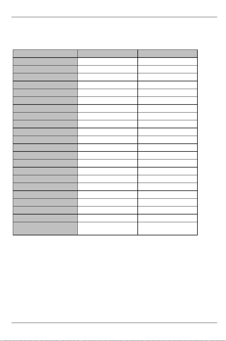
The table shows two assembly versions of this system board as an example.
Function Version D1224-B1X Version D1238-A1X
Processor socket FC-PGA 370 FC-PGA 370
Processor Celeron or Pentium III Celeron or Pentium III
Formfactor
Front Side Bus in MHz 66/100/133 66/100/133
Chipset VIA Apollo Pro266 VIA Apollo Pro266
Memory sockets 2 DIMM 3 DIMM
PCI slots 3 3
AGP 4x Port 1 1
CNR slot Type B 1 1
System monitoring - - - Thermal Management - - - Wake On LAN 1 1
Basic Alert On LAN II - - - Chipcard reader x x
Save to Disk (ACPI S4) x x
Save to RAM(ACPI S3) x x
Game/midi port x x
LAN onboard - - - Audio onboard AD1885 AD1885
VGA onboard - - - USB ports extern 2 2
USB ports intern 3 - internal connector
1 - via CNR connector
ATX
ATX
3 - internal connector
1 - via CNR connector
2 - English A26361-D1238-Z180-2-7619
Page 11
Mechanics
Mechanics
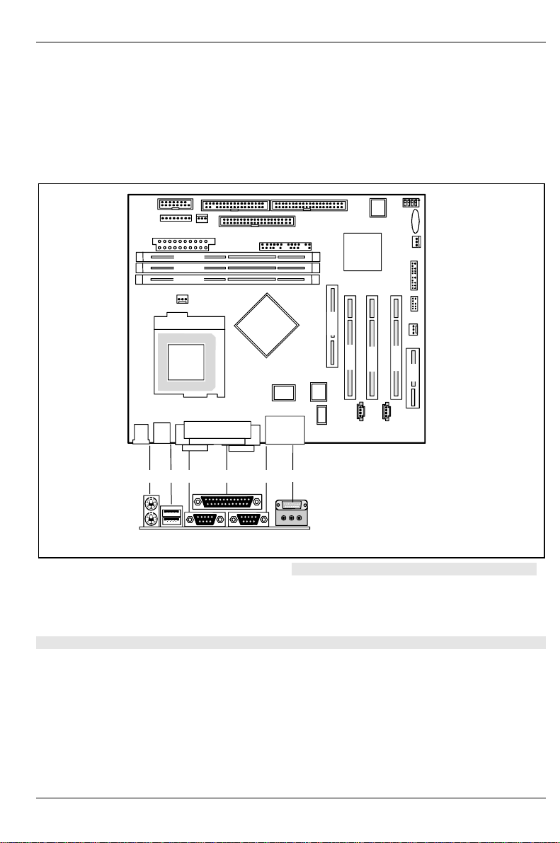
Layout System board D1238 and D1224
µ-ATX 9,6" x 8’’ (243.84 mm x 203.2 mm)
Some of the following connectors are optional and may therefore not be included on your system
board.
DIMM 3
DIMM 2
DIMM 1
AGP
2
1 = PS/2 mouse port
2 = PS/2 keyboard port
3 = USB ports 1 and 2
4 = Serial port 1
5 = Parallel port
31 4 5 6
PCI 1
7
8a 8c8b
6 = Serial port 2
7 = Game/Midi port
8a = Audio Line-Out
8b = Audio Line-In
8c = Audio Micro-In
PCI 3
PCI 2
CNR
The components and connectors marked are not necessarily present on the system board.
A26361-D1238-Z180-2-7619 English - 3
Page 12
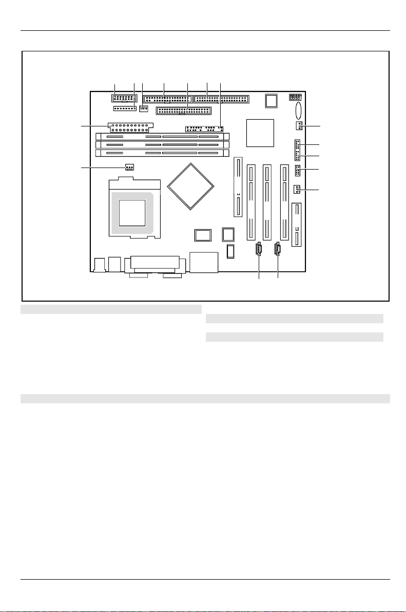
Mechanics
r
1234 5
16
DIMM 3
DIMM 2
DIMM 1
15
1 = Chipcard reader interface or serial port 2
2 = Power supply monitoring
3 = Cover monitoring
4 = Floppy disk drive
5 = IDE drives 3 and 4 (secondary)
6 = IDE drives 1 and 2 (primary)
7 = Connector for control panel and
loudspeake
67
AGP
PCI 1
14
PCI 3
PCI 2
CNR
13
9 = USB port F
10 = USB port E
11 = USB port D
12 = Fan 2 (e. g. for the processor)
13 = CD audio input
14 = AUX audio input
15 = Fan 1 (e. g. for the processor)
16 = Power supply
8
9
10
11
12
8 = Wake On LAN
The components and connectors marked are not necessarily present on the system board.
4 - English A26361-D1238-Z180-2-7619
Page 13
Connectors
Some of the following connectors are optional!
!
Connectors
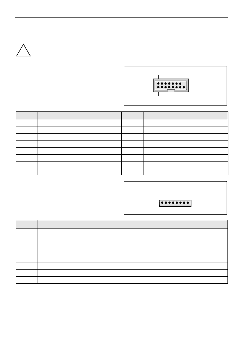
Serial chipcard reader or internal
2
serial port 2 (COM 2)
external via optional cable
1
Pin Signal Pin Signal
1 DCD2 2 DSR 2
3 SIN 2 4 RTS 2
5 SOUT 2 6 CTS 2
7 DTR 2 8 PC_On_Strobe
9 GND 10 VCC Auxiliary
11 EXT SMI (low asserted) 12 VCC
13 RESET (high asserted) 14 GND
15 GND 16 Key
Power supply monitoring
Pin Signal
1 Monitor on
2 PS FAN off request (low asserted)
3 PS FAN full on (low asserted)
4 PS FAN pulse
5 SMB CLK
6 SMB DATA
7 VCC EEPROM
8 GND
1
A26361-D1238-Z180-2-7619 English - 5
Page 14
Connectors
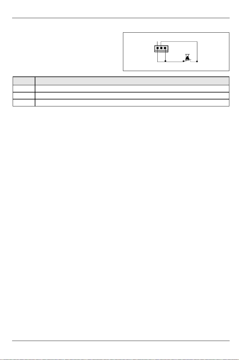
Intrusion connector for case open detect for optional push-button (opener)
Pin Signal
1 GND
2 Case open (low asserted)
3 Intrusion switch present (low asserted)
1
6 - English A26361-D1238-Z180-2-7619
Page 15
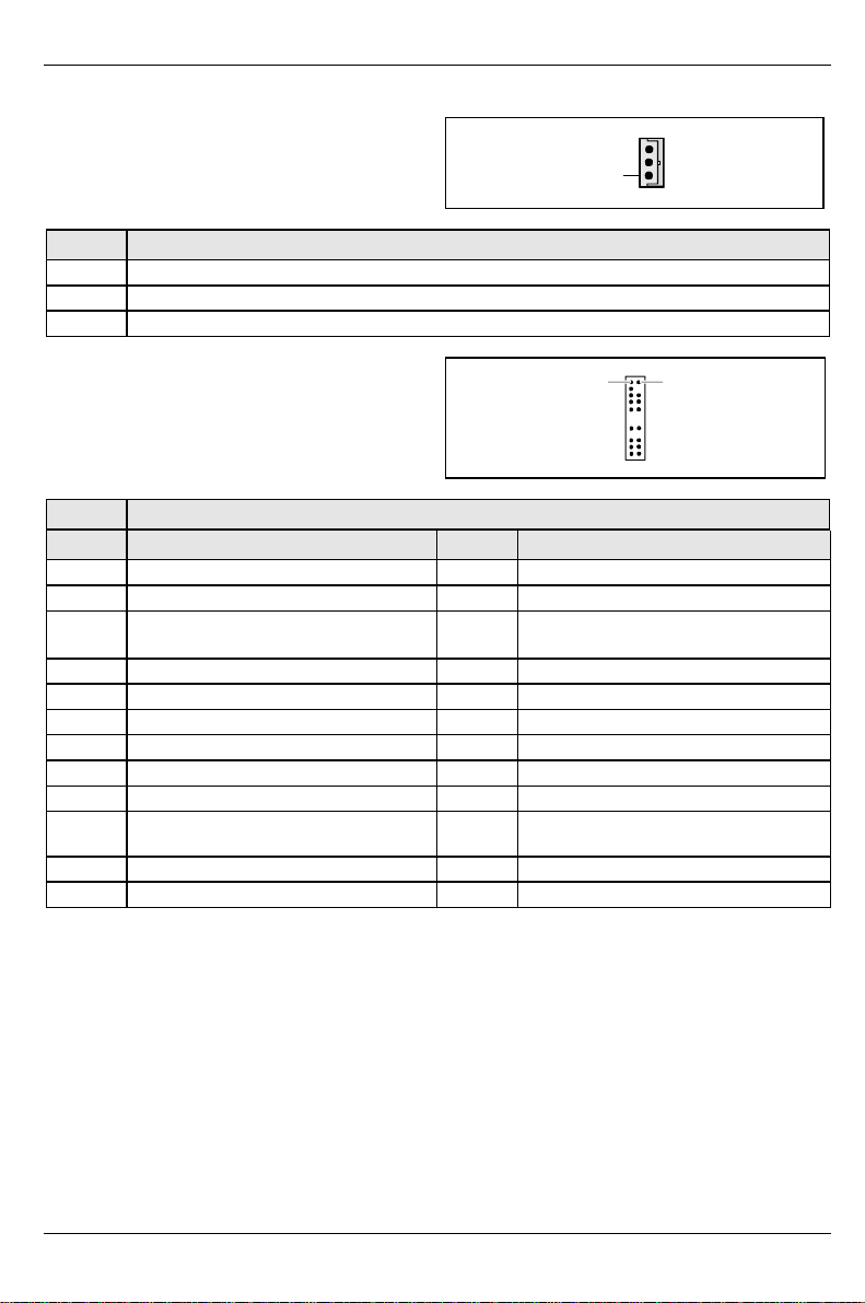
Connectors
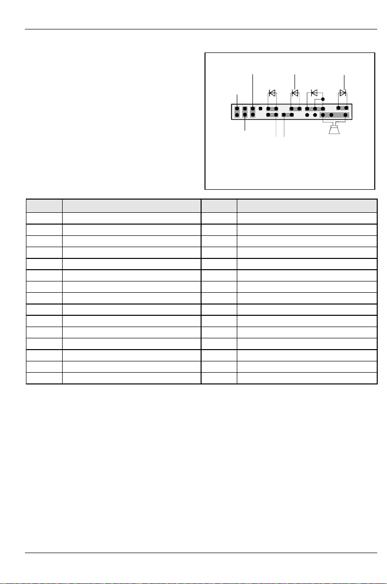
Front panel connector
Power On/Off
1)
Reset
1)
Sleep
1) Cableis not included in the delivery scope.
2) Thesame interface
3) 2pin or 3pin connector possible
Message LED
1)
HD-LED
SCSI LED Input
1)
Power On
1) 3)
LED
2)1)
Sleep LED
Speaker
Pin Signal Pin Signal
1 Sleep LED (Cathode) 2 Speaker
3 Sleep LED (Anode) 4 Key
5 Key 6 GND
7 PowerON_LED (Anode) 8
1)
VCC or GND
9 PowerON_LED (Anode) 10 Keypin
11 PowerON_LED (Cathode) 12 Key pin
13 Message LED (Anode) 14 Key
15 Message LED (Cathode) 16 Notconnected
17 Key 18 SCSI LED input (low asserted)
19 HD_LED (Anode) 20 SCSI LED input (low asserted)
21 HD_LED (Cathode) 22 Not connected
23 GND 24 Key
25 Power button (low asserted) 26 GND
2)
27
reserved 28 GND
29 Reset button (low asserted) 30 GND
1) Pin 8 is connected to VCC if audio is not onboard.
Pin 8 is connected to GND if audio is onboard.
2) The sleep button (optional) functions only for operating systems with APM (not with ACPI).
1
2
2)
A26361-D1238-Z180-2-7619 English - 7
Page 16
Connectors
Wake On LAN (WOL) connector
Pin Signal
1 VCC Auxiliary
2 GND
3 Wake pulse (high asserted)
1
USB port - Dual channel
Pin Signal
Pin Signal Pin Signal
1 VCC Dual (max. 250mA) 2 VCC Dual (max. 250mA)
3 Reserved 4 Key
5
7 Data positive 8 Data negative
9 GND 10 Over current (low asserted)
11 Key 12 Key
13 Key 14 Key
15 VCC Dual (max. 250mA) 16 VCC Dual (max. 250mA)
17 Key 18 Key
19 Power supply on
21 Data positive Data negative
22 GND Over current (low asserted)
Power supply on
(max 1 second low pulse)
(max 1 second low pulse)
6 GND
12
GND
8 - English A26361-D1238-Z180-2-7619
Page 17
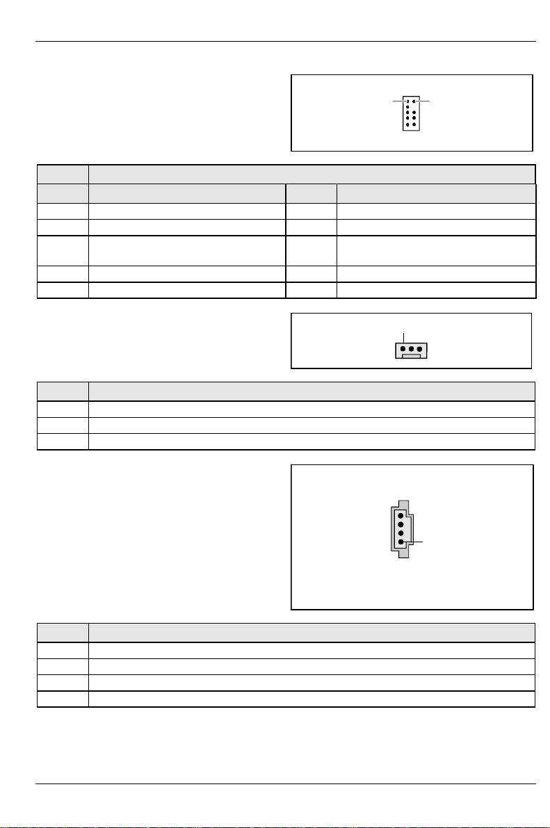
Connectors
USB port - Single channel
Pin Signal
Pin Signal Pin Signal
1 VCC Dual (max. 250mA) 2 VCC Dual (max. 250mA)
3 Reserved 4 Key
5
7 Data positive 8 Data negative
9 GND 10 Over current (low asserted)
Power supply on
(max 1 second low pulse)
6 GND
Fan 2 connector
(system fan - supervised)
Pin Signal
1 GND
2 +12 V
3 Fan sense
1
2
1
CD-ROM audio connector (internal)
1
Pin Signal
1 Left CD audio input
2 CD GND
3 CD GND
4 Right CD audio input
A26361-D1238-Z180-2-7619 English - 9
Page 18
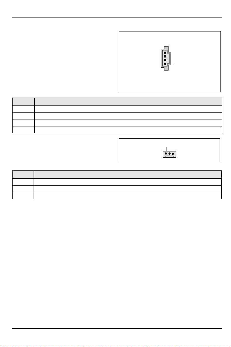
Connectors
Auxiliary (MPEG, TV) audio connector (internal)
Pin Signal
1 Left AUX audio input
2 Analog GND
3 Analog GND
4 Right AUX audio input
1
Fan 1 connector
(processor fan - controlled and supervised, only
for 3 pin fans)
Pin Signal
1 GND
2 Controlled fan voltage (0 V / 6...12 V)
3 Fan sense
1
10 - English A26361-D1238-Z180-2-7619
Page 19
Connectors
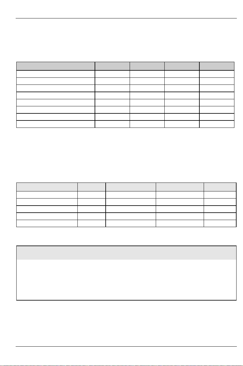
Configuration
Functions controlled by the configuration switch
Function SKP RCV FWP PSS
Password skip on X X X
Off off X X X
Recovery BIOS X on X X
Off X off X X
Floppy write protect X X on X
Off X X off X
Low auxiliary power supply (<2 A) X X X on
High auxiliary power supply X X X off
PSS must be switched on for systems with not enough 5 V auxiliary power for all its self powered
wake devices (WakeOnLAN, USB, PCI) in S3-S4.
Power
Power requirement
Source Voltage Maximum variation Maximum current Comment
Main power supply +5.0 V ±5 % 15 A
Main power supply +12 V ±10 % 350 mA
Main power supply -12 V ±10% 200 mA
Main power supply +3.3 V ±5 % 4 A
Auxiliary power supply +5.0 V ±5 % 2 A
Power loadability
Fuse
number
A26361-D1238-Z180-2-7619 English - 11
Maximum fuse
current
1 750 mA Keyboard port Not specified
2 500 mA Universal serial bus (USB) Port A 500 mA
3 500 mA Universal serial bus (USB) Port B 500 mA
Function Maximum function current
Mouse port Not specified
Game port Not specified
VGA connector Minimum 50 mA
Page 20

Documentation
Documentation
Ê Insert the "Drivers & Utilities" CD.
Ê If the CD does not start automatically, run the START.EXE file in the main directory of the CD.
Ê Select your system board or your device.
Ê Select Documentation.
Ê Select - Technical Manuals
Ê Select - Technical Manuals (BIOS)
You may have to install the Acrobat Reader - Software on the CD-ROM
(path: utls/acrobat) before reading!
i
For more details please read the according readme.txt files.
Installing drivers
Ê Insert the "Drivers & Utilities" CD.
Ê If the CD doesn't start automatically call the START.EXE file in the main directory of the CD.
Ê If the system board list is displayed select the system board or select under Driver the
operating system used and the audio and video drivers.
Upgrading main memory
Support: The system needs at least one module.
Size: From 64 Mbytes up to 3 GB DDR-DRAM (with next 512 Mbit-technologie)
Technology: PC200 or PC266 unbuffered DIMM modules.
Granularity: For one socket 64, 128, 256, 512 MB or 1GB
12 - English A26361-D1238-Z180-2-7619
184 pin, 2.5 V, 64 bit, 72 bit (with ECC), DDR-DRAM
8 M, 16 M, 32 M, 64M and 128M x 64 bit
8 M, 16 M, 32 M, 64M and 128M x 72 bit
As option ECC and EC modules can be used simultaneously respective
functionality.
Mix of PC200 and PC266 DIMMs is possible, but all modules will only work at PC200
speed.
Page 21

Troubleshooting
Troubleshooting
Message BIOS update
The System BIOS provides optimum support for the processor you have chosen. If the message
BIOS update for installed CPU failed
appears the microcode required for the processor inserted must still be loaded. Further information
on this is available in the "BIOS Setup" manual on the "Drivers & Utilities" CD provided.
The screen stays blank
If your screen stays blank this may have the following cause:
The wrong RAM memory module has been inserted
Ê See the chapter "Main Memory" for information which memory modules can be used.
ACPI S3 (Save-to-RAM) and/or ACPI S4 (Save-to-Disk) doesn't work
This system board is fully compliant for ACPI S3 and S4. Therefore it is PC99 certified by Microsoft.
If you have any problems with ACPI please ensure that all of your components are supporting
ACPI S3 and S4.
− Operating system
− Hardware and drivers of controllers (e. g. VGA, audio, LAN, SCSI controllers).
For further information please refer to http://developer.intel.com/technology/iapc/involve.htm .
A26361-D1238-Z180-2-7619 English - 13
 Loading...