

Page 1

System
Operating Manual
LIFEBOOK E780
Page 2

Are there ...
... any technical questions or problems?
Please contact:
• our Hotline/Service Desk (see Service Desk list or visit: "
http://ts.fujitsu.com/support/servicedesk.html")
• your sales partner
• your sales office
Latest information about our products, u seful tips, updates etc. is available
on our website: "
http://ts.fujitsu.com"
You can obtain automatic driver updates at: "http://support.de.ts.fujitsu.com/de/support/index.html"
Page 3

Page 4

Copyright
Fujitsu Tech
nology Solutions 2009 11/09
Published by
Fujitsu Technology Solutions GmbH
Mies-van-der
-Rohe-Straße 8
80807 Munich, Germany
Contact
h
ttp://ts.fuji
tsu.com/support
All rights reserved, including intellectual property rights. Technical d ata is subject to changes; del iverability is dependent
on availability. No guarantee of completeness, topicality or correctness of the data and illustrations is given and any
liability asso
ciated therewith is excluded. Brand names may be protected trademarks of the respective manufacturer
and/or protected by copyright. Their use by third parties for their own purposes could represent a violation of the
rights of the owner. For more information, see "
http://ts.fujitsu.com/terms_of_use.html"
Order No. Fujitsu Technology Solutions GmbH: A26391-K310-Z200-1-7619, edition 1
Page 5

LIFEBOOK E780
Operating Manual
Innovative technology 7
Ports and operating elements 9
Important notes 12
First-time setup of your device 15
Working with the notebook 18
Security functions 54
Connecting external devices 64
Removing and installing components
during servicing 71
Settings in BIOS Setup U tility 78
Troubleshooting and tips 80
Technical data 88
Manufacturer’s notes 92
Index 99
Page 6

Microsoft, MS, Windows XP, Windows Vista and Windows 7 are registered
trademarks of the Microsoft Corporation.
Adobe Reader is a trademark of Adobe Systems Incorporated.
MultiMediaCard is a registered trademark of Infineon Technologies AG
Sony and Memory Stick are registered tra demarks of Sony Electronics, Inc.
All other trademarks referenced are trademarks or registered tra demarks of their
respective owners, whose protected rights are acknowledged.
Copyright © Fujitsu Technology Solutions GmbH 2009
All rights reserved, including rights of translation, reproduction by printing, copying
or similar methods, in part or in whole.
In the event of violations, perpetrators will be liable to prosecution for damages.
All rights reserved, including rights created by patent grant or registration of a utility model o r design.
Subject to availability and technical modifications.
Page 7

Contents
Contents
Innovativetechnology ................................................................. 7
Furtherinformation ...................................................................... 7
Notational co nventions .................................................................. 8
Ports and operating elemen
ts ..........................................................
9
Importantnotes ........................................................................ 12
Safety notes ............................................................................ 12
Additional safety notes for devices w ith radio components . . . . . ............................. 12
Energy saving .......................................................................... 13
Energy saving under Windows ....................................................... 13
Travelling with your notebook ............................................................ 13
Before you travel ................................................................... 13
Notebook: transporting ............................................................... 14
Cleaning thenotebook .................................................................. 14
First-time setup o
fyourdevice .........................................................
15
Unpacking and che
ckingthe device ......................................................
15
Selectingalocat
ion .....................................................................
16
Mains adapter con
necting ...............................................................
16
Switchingonthe
device for the first time ..................................................
17
Working with thenotebook ............................................................ 18
Status indicators ........................................................................ 18
Switching on the notebook . . . . ........................................................... 21
Notebook: switch ing off .................................................................. 21
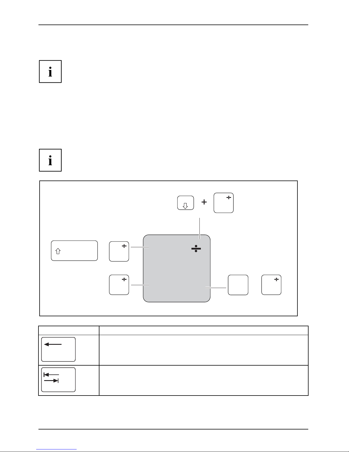
Keyboard ............................................................................... 22
Virtual numerickeypad .............................................................. 24
Keycombinations ................................................................... 24
Country and keyboard s ettings ....................................................... 26
Application keys ........................................................................ 27
Programming theapplication keys .................................................... 28
Touchpad andtouchpadbuttons .......................................................... 28
Moving thepointer .................................................................. 28
Selecting an item .................................................................... 29
Executing commands . . . . . ........................................................... 29
Dragging items ...................................................................... 29
LCDscreen ............................................................................ 30
Webcam ............................................................................... 31
Rechargeable battery ................................................................... 32
Charging, caring forand maintaining the battery ....................................... 32
Removing andinstalling thebattery ................................................... 32
Module ................................................................................. 34
Removing a module . . . . . . ........................................................... 35
Installing a module .................................................................. 36
Opticaldrive ............................................................................ 36
Handling datacarriers ............................................................... 36
CD/DVD indicator ................................................................... 37
Inserting or removing adatacarrier ................................................... 37
Manual removal (emergency removal) . . . . ............................................ 38
Removing and fittingthe dust removalcover (ventilationslotcover) ......................... 38
Usingthe power-management features ................................................... 40
Fujitsu Technology Solutions 3
Page 8

Contents
Memory cards .......................................................................... 41
Supported formats .................................................................. 41
Inserting thememorycard ........................................................... 41
Removing thememorycard .......................................................... 42
PC cardsand ExpressCards ............................................................. 43
Inserting thecard ................................................................... 43
Removing thecard .................................................................. 44
Loudspeakers and microphones . . ........................................................ 44
Integrated 56k modem . . ................................................................ 45
Connecting notebook modem to telephone wall socket . . . .............................. 46
SIMcard ............................................................................... 47
Inserting theSIM card ............................................................... 47
Removing aSIM card ............................................................... 47
Wireless LAN/ Bluetooth (device-depe ndent) / UMTS (device-dependent) ................... 48
Switching the wireless components on and off ......................................... 48
Setting up WLAN access ............................................................ 49
Access viaUMTS ................................................................... 49
Ethernet and LAN ....................................................................... 49
Your Port Replicator (optional) . . . ........................................................ 50
Portsonthe Port Replicator .......................................................... 50
Connecting the notebook to the Port Replicator . . . . . .................................. 51
Connecting the mains adapter to the Port Replicator . .................................. 52
Switching on the notebook via the port replicator . . . . . .................................. 52
Switching offnotebook viaPortReplicator ............................................. 52
Disconnecting the notebook from the Port Replicator .................................. 53
Securityfunctions ..................................................................... 54
Configuring the fingerprint sensor ........................................................ 54
Usinga Kensington Lock ................................................................ 55
Configuring password protection in BIOS SetupUtility ...................................... 55
Protecting BIOS Setup Utility (supervisor and user password) . .......................... 55
Password protection for booting of the operating system . .............................. 56
Password protection for theharddisk ..................................................... 57
Activating harddiskprotection ........................................................ 57
Deactivating harddiskprotection ..................................................... 58
Boot from RemovableMedia ............................................................ 58
Owner Information (device-dependent) . . . ................................................. 59
Virus Warning (device-dependent) . . . . . . ................................................. 59
SmartCard reader ....................................................................... 60
Inserting theSmartCard ............................................................. 60
SmartCard as software protection (SmartCase
™
Logon+) .............................. 61
Trusted Platform Module (TPM) (device-dependent) . . . . . .................................. 62
Enabling TPM ....................................................................... 63
Disabling TPM ...................................................................... 63
Connectingexternaldevices ........................................................... 64
Connecting an external monitor . . ........................................................ 65
Connecting external devices to the parallel or serial port . .................................. 66
Port settings ........................................................................ 66
Device drivers ...................................................................... 66
Connecting USB devices ................................................................ 67
Connecting an external SATA hard disk (eSATA) . . . . . .................................. 68
Safe removalofeSATA and USBdevices ............................................. 68
Connecting FireWire devices . ............................................................ 69
4 Fujitsu Technology Solutions
Page 9

Contents
Connecting external audio devices ....................................................... 69
Microphone port / Line In . ........................................................... 69
Headphone port . . . .................................................................. 70
Removing and installing components during servicing .. . . ............................. 71
Notesoninstalling andremoving boards andcomponents .................................. 71
Preparing to remove components . ....................................................... 72
Installing and removing memory expansion . . . . ............................................ 72
Removing acover ................................................................... 73
Removing memory modules .......................................................... 73
Installinga memory module .......................................................... 74
Attaching thecover .................................................................. 74
Removing andinstalling theharddisk .................................................... 75
Removing acover ................................................................... 75
Removing aharddisk ............................................................... 76
Installinga hard disk ................................................................. 76
Attaching thecover .................................................................. 77
Finishing component removal . ........................................................... 77
Settings in BIOS Setup Utility . . . ....................................................... 78
Starting the BIOS SetupUtility ........................................................... 78
OperatingBIOSSetup Utility ............................................................. 78
Exiting BIOS SetupUtility ................................................................ 79
Exit Saving Changes - save changes and exit BIOS Setup Utility . . ..................... 79
Exit Discarding Changes – Discard changes and exit BIOS Setup Utility . . . .............. 79
Load Setup Defaults – Copy Standard Entries . ........................................ 79
Discard Changes – Discard changes without exiting the BIOS Setup Utility . .............. 79
Save Changes - save changes without exiting the BIOS Setup Utility . . . . . . .............. 79
Save Changes and Power Off ....................................................... 79
Troubleshootingandtips .............................................................. 80
Help if problems occur ................................................................... 81
Restoring the hard disk contents under Windows . . ........................................ 81
The notebook’s date or time is incorrect ................................................... 82
When certaincharacters areentered on thekeyboard, only numerals arewritten ............. 82
The notebook’s LCD screen remains blank . . . . ............................................ 82
The LCD screen is difficult to read ........................................................ 82
Theexternalmonitorremains blank ...................................................... 83
Theexternalmonitorisblank or theimage is unstable ..................................... 83
The notebook cannot be started . . . ....................................................... 84
The notebook stops working . . ........................................................... 84
The printer does not print . . . . . ........................................................... 85
The radio connection to a network does not work . . ........................................ 85
Acoustic warnings ....................................................................... 85
Errormessageson thescreen ........................................................... 86
Technical data ......................................................................... 88
Notebook . . ............................................................................. 88
Port Replicator (optional) ................................................................ 90
Rechargeable battery ................................................................... 90
Mains adapter .......................................................................... 91
Mainsadapter 80W .................................................................. 91
100W mains adapter . . . . . ........................................................... 91
Fujitsu Technology Solutions 5
Page 10

Contents
Manufacturer’snotes .................................................................. 92
Energy Star ............................................................................ 92
Disposal and recycling .................................................................. 92
DeclarationsofConformity ............................................................... 92
CE marking ............................................................................ 93
Regulatory notices ...................................................................... 93
Regulatory information for notebooks without radio device .............................. 93
DOC (Industry CANADA) notices . . . . ................................................. 95
FCC Regulatory information for notebooks with radio device . . .......................... 96
Index .................................................................................. 99
6 Fujitsu Technology Solutions
Page 11

Innovative technology
Innovative technology
... and ergonomic design make your device a reliable and convenient companion.
The device boots very quickly, is ready for immediate use and offers a particularly
long operating time because of its high capacity battery.
With the user-friendly "BIOS Setup Utility" you can control your notebook’s hardware and better
protect your system against unauthorised access by using the powerful password properties.
Information on the connections and user components of your notebo ok can
be found in "
Ports and operating elements", Page 9.
Further information
The Windows drivers for your device can be found on our Internet
website. The factory installation of your device does not support any
other operating system. Fujitsu Technology Solutions accepts no liability
whatsoever if any other operating system is used.
Software oriented c omponents of these instructions refer to Microsoft products,
if they come within the scope of the delivery.
If you install other software products, pay attention to the operating
instructions of the manufacturer.
Fujitsu Technology Solutions 7
Page 12

Innovative technology
Notational conventions
Pay particular attention to text marked with this symbol. Failure to observe
these warnings could pose a risk to health, damage the device or lead
to loss of data. The warranty will be i nvalidated if the device becomes
defective through failure to observe these warnings.
Indicates importan t informat
ion for the proper use of the device.
►
Indicates an activity that must be performed
Indicates a result
This font
indicates data entered usin
g the keyboard in a program dialogue or at
the c ommand line, e.g. your p
assword (Name123) or a command used to
start a program (start.ex
e)
This font
indicates information that is displayed on the screen by a program, e.g.:
Installation is complete.
This font
indicates
• terms and texts used in a software interface, e.g.: Click on Save
• names of programs or files, e.g. Windows or setup.exe.
"This font"
indicates
• cross-references to another section, e.g. "Safety information"
• cross-references to an external source, e.g . a web address: For more
information, go to "
http://ts.fujitsu.com"
• Names of CDs, DVDs and titles or designations of other materials, e.g.:
"CD/DVD Drivers & Utilities" or "Safety" Manual
Key
indicates a key on the keyboard, e.g:
F10
This font
indicates terms and texts that are emphasised or highlighted, e.g.: Do
not switch off the device
8 Fujitsu Technology Solutions
Page 13
Ports and operating elements
Ports and operating elements
This chapter presents the individual hardware components of your device. It gives
an overview of the indicators and ports of the device. Please familiarise yourself with
these components before you start to work with the device.
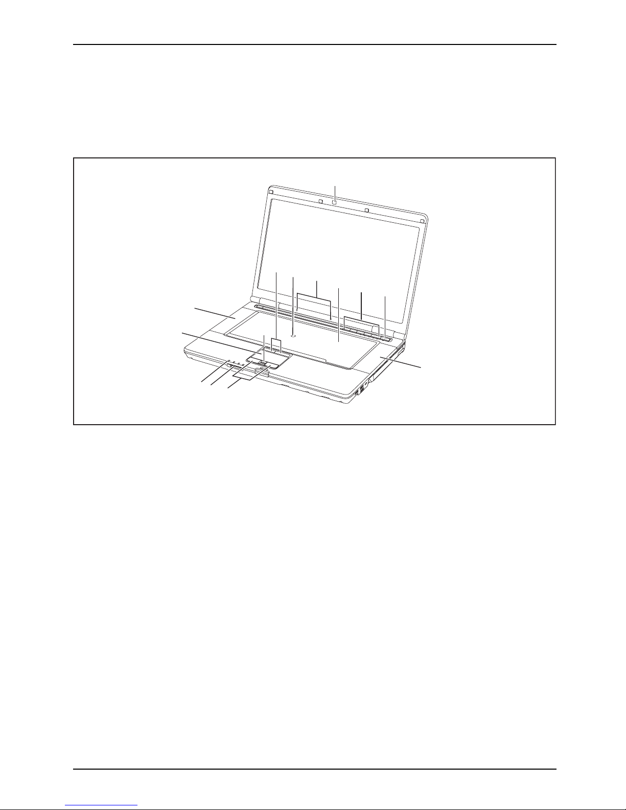
6
7
8
5
12
1*
13
9*
11
10
8
3*
2
4
1 = WebCam (* device-dependent)
2 = TouchStick bu
ttons
3 = TouchStick (* op tional)
4 = Microphones
5 = Keyboard
6 = Applicatio
n buttons
7 = ON/OFF switch
8 = Loudspeakers
9 = Fingerprint s
ensor (* optional)
10 = Touchpad buttons
11 = Memory card s
lot
12 = Status indicators
13 = Touchpad
Fujitsu Technology Solutions 9
Page 14
Ports and operating elements
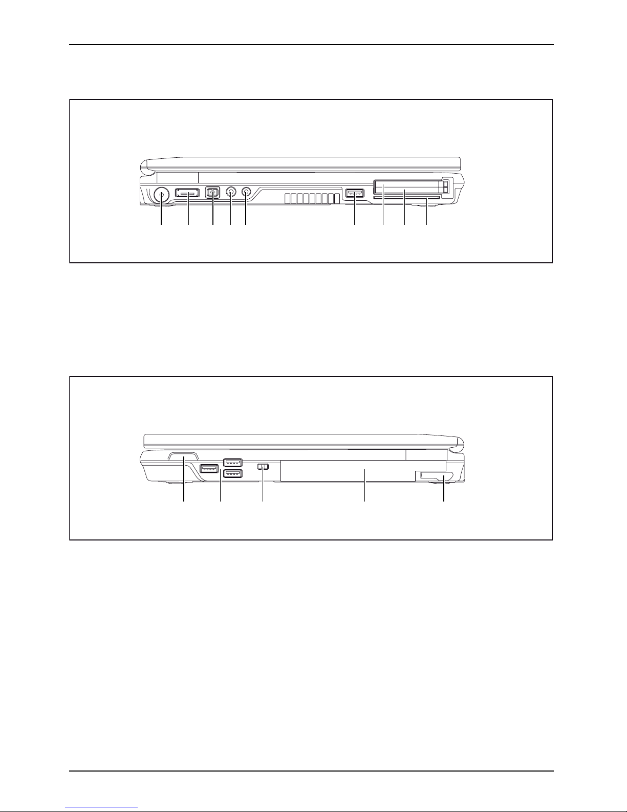
Left panel
1 2 3 4 5 6 7 8 9
1 = DC input connector (DC IN)
2 = eSATA port
3 = FireWire port
4 = Microphone port
5 = Headphones port
6 = USB port
7 = ExpressCard slot
8 = PC card slots
9 = SmartCard reader
Right side
21 3 4 5
1 = ON/OFF switch for radio components
2 = USB ports
3 = Kensington Lock
4 = Module bay with optical drive
5 = Eject lever for module
10 Fujitsu Technology Solutions
Page 15

Ports and operating elements
Rear
1 2 3 4 5 6
1 = Kensington Lock
2 = Modem port
3 = VGA monitor port
4 = Serial port
5 = LAN port
6 = DisplayPort
Underside
1
3
4
5
6
2
2
1 = Hard disk service compartment
2=B
attery lock
3 = Rechargeable battery
4 = Memory service compartment
5=P
ort for Port Replicator
6 = Ventilation slot cover
Fujitsu Technology Solutions 11
Page 16

Important notes
Important notes
ImportantnotesNotes
This chapter contains essential sa fety information which must be followed
when working with your notebook. Other notes also provide useful information
which will help you with your notebook.
Safety notes
SafetynotesNotes
Please note the information provided in the "Safety" manual and
in the following safety notes.
Please pay special attention to the sections in the manual marked
with the symbol on the left.
When connecting and disconnecting cables, observe the relevant
notes in this operating manual.
Read the information on the ambient conditions in the "
Technical data", Page
88 and "First-time setup of your device", Page 15 before preparing your
notebook for use and switching it on for the first time.
When cleaning the device, please observe the r elevant notes in the
section "
Cleaning the notebook", Page 14.
Pay attention to the additional sa fety notes for devices with wireless
components provided in the "Safety" manual.
Please refer to the notes in the chapter "
Removing and ins talling
components during s ervicing", Page 71.
This notebook complies with the relevant safety regulations for data processing
equipment. If you have questions about using your notebook in a particular area,
please contact your sales outlet or our Hotline/Service Desk.
Additional safety notes fo
r devices with
radio components
Radiocomponent:WirelessLAN:Bluetooth,safetynotes
If a radio component (Wireles
s LAN, Bluetooth, UMTS) is integrated in your no tebook, you
must be sure to observe the fol
lowing safety notes when using your notebook:
• Switch off the radio componen
ts when you are in an aircraft or driving in a car.
• Switch off the radio components when you are in a hospital, an operating room or near a medical
electronics system. The transmitted radio waves can impair the operation of medical devices.
• Switch off the radio componen
ts when you let the device get near flam mable
gases or into hazardous envi
ronments (e.g. petrol station, paintshops), as the
transmitted radio waves can
cause an explosion or a fire.
For information on how to sw
itch radio components on and off, see chapter
"
Switching the wireless co
mponents on and off", Page 48.
12 Fujitsu Technology Solutions
Page 17

Important notes
Energy saving
NotesEnergyEnergysaving
Switch the notebook off when it is not in use. Switch off external, connected devices if you
are not using them. If you use the energy saving functions, the noteboo k uses less energy.
You will then be able to work for longer before having to recharge the battery.
Energy efficiency is increased and the environmental impact is reduced.
You save money while protecting the environment.
Energy saving under Windows
► Make use of the power management features (see ""Using the power-management features",
Page 40").
Travelling with your notebook
MobileoperationNotesTrans portationNotebook
Please observe the points listed below when travelling with your notebook.
Before you t ravel
► Back up important data stored on your hard disk.
NotebookTravel,notebook
► Switch o ff the radio component for da
ta security reasons. With data traffic via a wireless
connection, it is also possible fo r u
nauthorised third parties to receive data.
Information on activating data enc
ryption is provided in the documentation
for your radio comp onent.
► If you w ish to use your notebook d uring a flight, first check with the flight
attendants if it is OK to do so.
When travelling in other countrie
s
► If you are travelling a broad, check that the mains adapter can be operated with the
local mains voltage. If this is not the case, obtain the appropriate mains adapter for
your notebook. Do not use any other voltage converter!
► Check whether the local mains vo
ltage and the power cable are compatible. If this is
not the case, buy a pow er cable th
at matches the local conditions.
► Enquire with the corresponding government office of the country you will be
travelling in as to whether you may operate the radio component integrated in
your notebook there (see also "
CE marking " , Page 93).
Fujitsu Technology Solutions 13
Page 18

Important notes
Notebook: transporting
Protect the notebook from severe shocks and ext reme temperatures
(e.g. direct sunlight in a car).
► If your device has an optical drive, remove all data media (e.g. CD, DVD) from the drives.
TransportationNotebook
► Switch the notebook off.
► Unplug the mains adap ter and all external devices from the power socket.
► Disconnect the mains adapter cable and the data cables for all external devices.
► Close the LCD screen.
► To protect against damaging jolts and bumps, use a notebook carrying
case to transp ort your notebook.
Cleaning the notebook
Do not clean any interior parts yourself; leave this job to a service technician.
Only use cleaning products designed for computers. N orma l household
cleaners and polishes can damage the markings on the keyboard and the
device, the paintwork or the notebook itself.
Ensure that no liquid enters the notebook.
The LCD screen very sensitive to scratches. Only clean the display
surface with a very soft, slightly damp cloth.
► Switch the notebook off.
CleaningNotesNotebookKeyboardTouchpadLCDscreenCrystalView display
► In order to prevent accidentially switc
hing the device on, remove the power cable from the mains
adaptor and remove the battery (see "
Rem
oving and installing the battery", Page 32).
The surface can be cleaned with a dry cloth. If particularly dirty, use a cloth which has
been moistened in mild do mestic detergent and then carefully wrung out.
To clean the keyboard and the touchpa d, if available, you can use disinfectant wipes.
Ensure that n o liquid enters the device.
14 Fujitsu Technology Solutions
Page 19

First-time setup of your device
First-time setup of your devic
e
First-timese tupGettingstarted
Please read the chapter "Important notes", Page 12.
If your device is equipped with a Windows operating system, the necessary
hardware drivers and sup plied software are already pre-installed.
Beforeyouswitchonthedeviceforthefirst time, connect it to the mains voltage
using the mains adapter, see "
Mains adapter connecting", Page 16.Themains
adapter must be con nected during the entire installation process.
A system test is performed when your device is first switched on. Various messages
can appear. The display may remain dark for a short time or may flicker.
Please follow the instructions on the screen.
NEVER switch off your device during the first-time setup process.
On delivery, the battery can be found in the battery compartment or in the accessories kit.
The battery must be charged if you want to operate your device u sing the battery.
When used on the m ove, the built-in battery pro vides the device with the necessary power. You
can increase the operating time by using the available energy-saving functions.
For instructions on how to connect external devices (e.g. mouse, printer) to your
device, please refer to the operating ma nual for y our device.
Unpacking and checking the d
evice
Should you discover any damage that occurred during transportation,
notify your local s ales outlet immediately!
► Unpack all the individual parts.
PackagingTransport
► Check your device for any visible damage which may have occurred during transp ortation.
You may need the packaging in the future, if you need to transport your device.
Fujitsu Technology Solutions 15
Page 20

First-time setup of your device
Selecting a location
SelectingalocationDeviceMainsadapter
Select a suitable location for the device before setting it up. Follow
the instructions below when doing so:
• Never place the device or the mains adapter on a heat-sensitive surface.
The surface could be dama ged as a result.
• Never place the device on a soft surface (e. g. carpeting, upholstered furniture,
bed). This can block the air vents and cause overheating and damage.
• The underside of the device heats up during normal operation. Prolonged contact
with the skin may become unpleasant or even result in burns.
• Place the device on a stable, flat, non-slippery s urface. Please note that the
rubber feet of the device may mark certain types of delicate surfaces.
• Keep other objects at least 100 mm away from the device and its
mains adapter to ensure adequate ventilation.
• Never cover the ventilation slots of the device.
• Do not expose the device to extreme environmental conditions. Protect
the device from dust, humidity, and heat.
Mains adapter connecting
PreparingforoperationMainsadapter
Observe the safety precautions in the enclosed "Safety" manual.
The supplied power cable conforms to the requireme nts of the country in
which you purchased your device. Make sure that the power cable is approved
for use in the country in which you intend to use it.
3
1
2
► Connect the power cable (1) to the
mains adapter.
► Plug the mains cable (2) into a mains outlet.
► Connect the mains adapter cable (3) to
the DC jack (DC IN) of the device.
16 Fujitsu Technology Solutions
Page 21

First-time setup of your device
Switching on the device for the first time
Switchingonforthefirsttime
On devices with ON/OFF switch for wireless components: Slide the ON/OF F sw itch
for wireless components to the ON position before switching on the device.
When you switch on the device for the first time, the supplied software is
installed and configured. Because this procedure must not be interrupted,
you should set aside enough time for it to be fully completed and connect
the device to the mains using the mains adapter.
During the installation process, DO NOT restart the device unless
you are requested to do so!
To make it easier to use your de
vice for the first time, the ope rating system
is pre-installed on the hard
disk.
► Switch on your device.
► During installation, follow the instructions on screen.
If a Windows o perating system is installed on your device, you will find mo re
information on the system and drivers, help programmes, updates, manuals etc.
on the device or on the Internet at "
http://ts.fujitsu.com/support".
Fujitsu Technology Solutions 17
Page 22

Working with the notebook
Working with the notebook
Notebook,operationNotebook
This chapter describes th e basics for operating your notebook. Please read the chapter
entitled "
Connecting external devices", Page 64 for instructions on how to connect
devices such as a mouse and a printer to the notebook.
Please refer to the notes in "Important notes", Page 12.
Status indicators
Statusindicatorpanel
The status indicators provide information about the status of the power supply,
the drives and the keyboard functions.
E
1
2
Indicator Description
Power-on indicator
Power-onindicatorIndicat or
• The indicator is illuminated: The notebook is switched on.
•Theindicatorflashes (1 second on/1 second off): The notebook is in power
saving mode.
• The indicator is not illuminated: The notebook is switched off or is in
Save-to-Disk mode.
18 Fujitsu Technology Solutions
Page 23
Working with the notebook
Indicator Description
Battery charging indicator
• The indicator lights up green: The mains adapter is connected and the installed
battery or batteries are already fully charged, or no battery is installed.
• The indicator lights up orange: The mains adapter is connected and the
installed battery or batteries are being charged.
•Theindicatorflashes orange: The mains adapter is connected and the installed
battery or batteries cannot be charged (the battery is too hot for charging).
• The indicato r is not illuminated: The mains adapter is not connected.
First battery indicator
• The indicator lights up green: The first battery is charged to between 51% an d
100% of maximum c apa city.
• The indicator slowly flashes green (1 second on/5 seconds off): The notebook
is in suspend mode and power is being supplied by the first battery. The first
battery is charged to between 51% and 100% of maximum capacity.
• The indicator lights up orange: The mains adapter is connected and the first
battery is being charged. The first battery is charged to between 13% and
50% of maximum capacity.
• The indicator slowly flashes orange (1 second on/5 seconds off): The notebook
is in suspend mode and power is being supplied by the first battery. The first
battery is charged to betwe en 13% and 50% of maximum capacity.
• The indicator flashes orange (for four seconds after installing the bat tery): The
battery charge level is being checked.
• The indicator lights up red: The mains adapter is connected and the first
battery is being charged. The first battery is charged to between 0% and 12%
of maximum capacity.
• The indicator slowly flashes red (1 second on/5 seconds off): The notebook
is in suspend mode and power is being supplied by the first battery. The first
battery is charged to between 0% and 12% of maximum capacity.
• The indicator flashes red (1 seco nd on/1 second off). Malfunction.
• The indicator is not illuminated: The first battery is not installed or is n ot charged.
Fujitsu Technology Solutions 19
Page 24

Working with the notebook
Indicator Description
Second battery indicator
• The indicator lights up green: The second battery is charged t o between 51%
and 100% of its capacity.
• The indicator slowly flashes green (1 second on/5 seconds off): The notebook
is in suspend mode and power is being supplied by the seco nd battery. The
second battery is charged to between 51% and 100% of its capacity.
• The indicator lights up orange: The mains adapter is connected and the second
battery is being charged. The second battery is charged to between 13% and
50% of its capacity.
• The indicator slowly flashes orang e (1 second on/5 seconds off): The notebook
is in suspend mode and power is being supplied by the seco nd battery. The
second battery is charged to between 13% and 50 % of its capacity.
• The indicator flashes orange (for four seconds after installing the battery): The
battery charge level is being ch ecked.
• The indicator lights up red: The mains adapter is connected and the second
battery is being charged. The second battery is charged to between 0% and
12% of its capacity.
• The indicator slowly flashes red (1 second on/5 seconds off): The notebook
is in suspend mode and power is being supplied by the seco nd battery. The
second ba ttery is charged to between 0% and 12% o f its capacity.
• The indicator flashes red (1 second on/1 second off). M alfunction.
• The indicator is not illuminated: The second battery is not installed or is not
charged.
Energy saving functions ind
icator
• The indicator is illuminate
d: The energy saving functions are enabled (e.g.
reduce screen brightness).
• The indicator is not illuminated: The energy saving functions have been
disabled.
Drive indicator
IndicatorCD/DVDind
icator
The indica tor is illuminated: The hard disk drive or the CD/DVD in the optical drive
of the notebook is being accessed.
Num Lock indicator
IndicatorNum Lock
The indicator is illuminated: The
Num
key has been pressed. The virtual
numerical keypad is activated. You can output the characters indicated on the
upper right of the keys.
Caps Lock indicator
Indica
tor
CapsLo
ck
The indicator is illuminated: The Caps Lock key has been pressed. All the
characters you type will appear in upper case. In the case of overlay keys, the
character printed on the upper left of the key will appear when that key is pressed.
Scroll Lock indicator
IndicatorScrollLock
IndicatorScrollLock
The indicator is illuminated: The key combination
Fn+Scr
has been pressed. The
effect that this key has varies between applications.
20 Fujitsu Technology Solutions
Page 25
Working with the notebook
Switching on the notebook
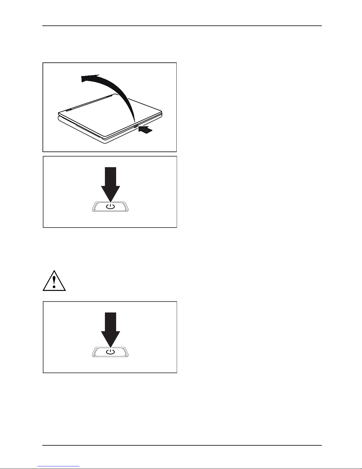
1
2
► Press on the unlocking lever (1).
Notebook
The monitor is unlocked.
► Lift up the LCD monitor (2).
► Press the ON/OFF swit
ch for about one
second to switch the
notebook on.
The power-on indicator of the notebook lights up.
Notebook: switching off
Back up your data and close all applications before you switch off your
device. Otherwise data might be lost.
► Shut down the opera ting system properly
(e.g. inWindowsviatheStart menu by
clicking Start Symbol – Shut Down – OK).
Notebook
► If the notebook is not switched off
automatically, press the ON/OFF s witch
for approx. five seconds.
► Close the LCD screen.
Fujitsu Technology Solutions 21
Page 26
Working with the notebook
Keyboard
KeyboardNumeric keypadNumerickeypadButtons
The keyboard of your notebook is subject to continuous wear through normal
use. The key markings are especially prone to wear. The key markings are
liable to wear away over the life of the notebook.
The keyboard has been designed to provide all the functions of an enhanced keyboard.
Some enhanced keyboard functions are mapped with key combinations.
The following description of keys refers to Windows. Additional functions supported by the keys
are described in the relevant manuals supplied with your application programs.
The figure below shows how to access the different characters on keys with overlaid functions.
The exa mple applies when the Caps Lock key has not been activated.
The illustrations shown below may differ from your actual device.
0
=
}
+
+
Num
Alt Gr
=
0
}
=
0
}
=
0
}
=
0
}
Key Description
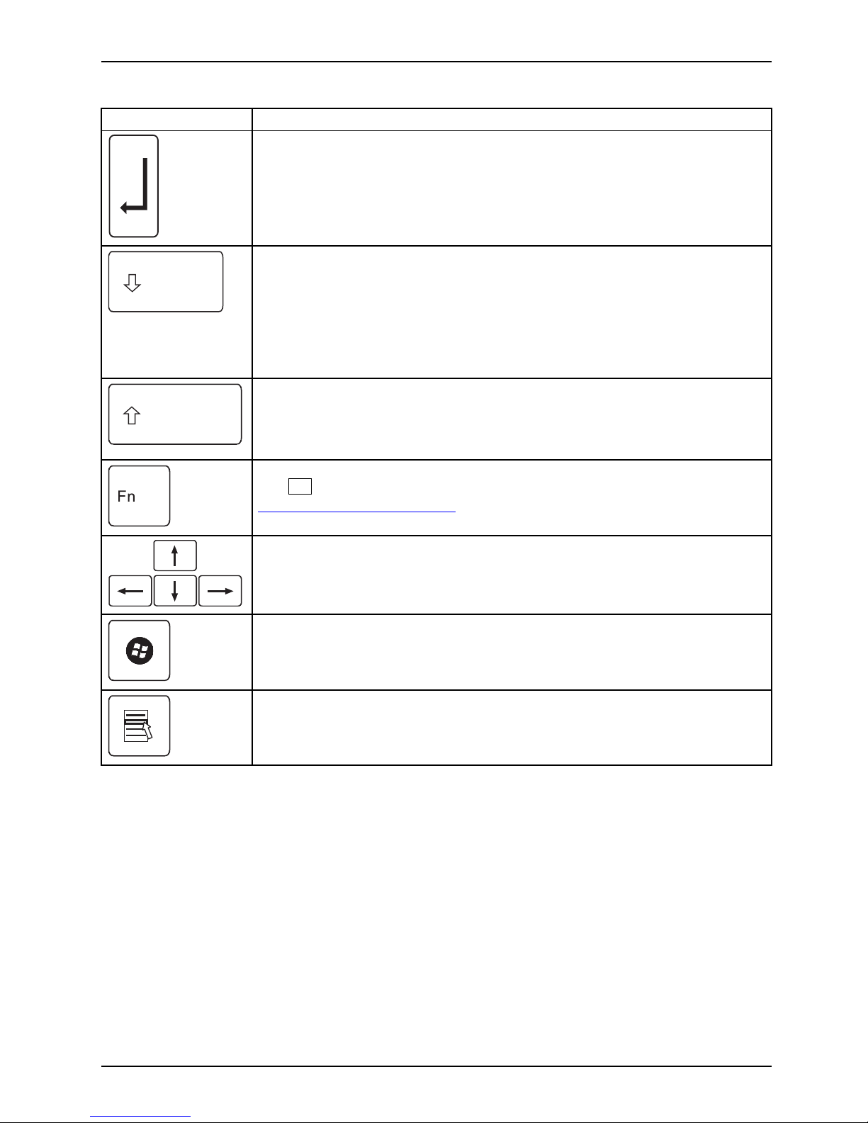
Backspace key
The Backspace key deletes the character to the left of the curso r.
BackspaceBackspace
Tab key
The Tab key moves the cursor to the next tab stop.
Tabkey
22 Fujitsu Technology Solutions
Page 27
Working with the notebook
Key Description
Enter key (return)
The Enter key terminates a command line. The command you have entered
is executed when you press this key.
EnterkeyReturnEnterLinefeed
Caps Lock key
The Caps Lock key activates the Caps Lock mode, and the corresponding
icon is displayed in the Windows information area. In Caps L ock mode, all
of the characters you type appear in upper case. In the case of overlay
keys, the character printed on the upper left of the key will appear when
that key is pressed. To cancel the Caps Lock function, simply p ress the
Caps Lock key again.
ShiftkeyCap sLock
Shift key
The Shift key causes uppercase characters to appear. In th e case of overlay
keys, the character printed on the upper left of the key appears when that
keyispressed.
ShiftkeyShift
Fn button
The
Fn
key enables the special functions indicated on overlay keys (see
"
Key combi nations", Page 24).
Fnkey
Cursor keys
The cursor keys move the cursor in the direction of the arrow, i .e. up, down,
left, or right.
CursorkeysCursorcontrolkeys
Start key
The Start key opens the Windows Start menu.
Startkey
Menu key
TheMenukeyinvokestheme
nu for the marked item.
Fujitsu Technology Solutions 23
Page 28
Working with the notebook
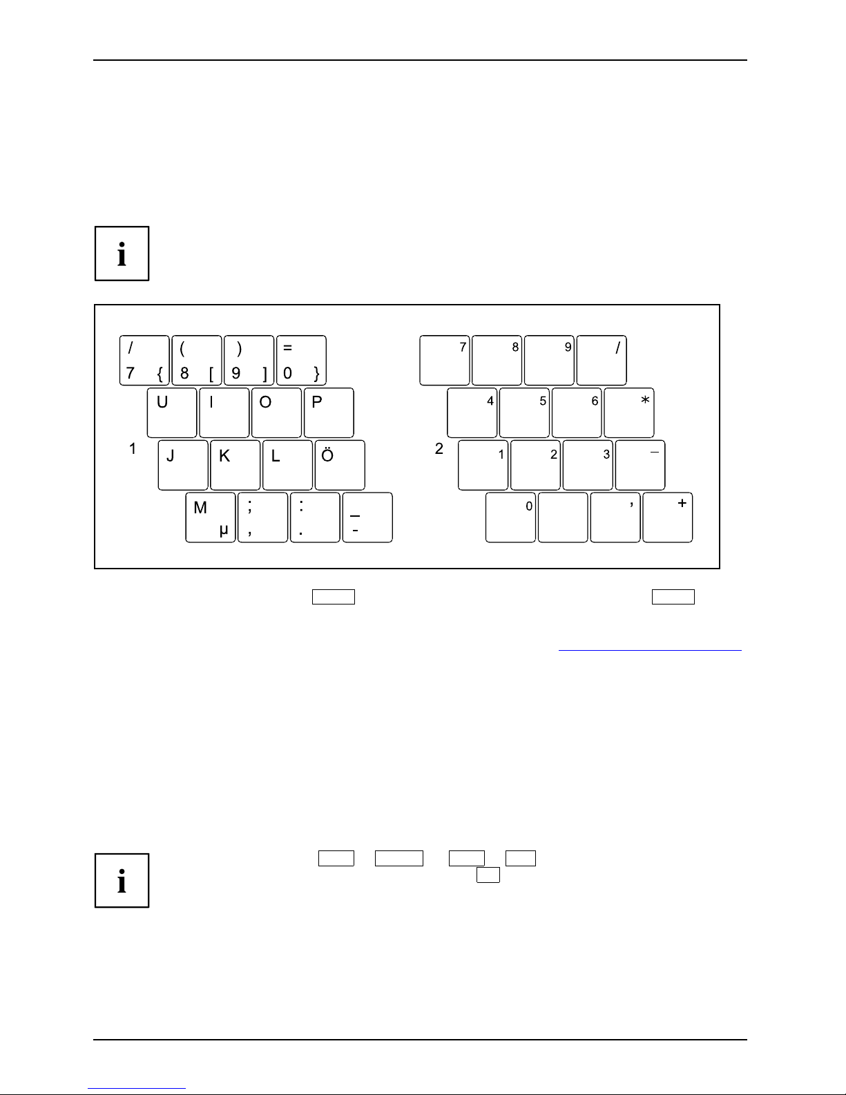
Virtual numeric keypad
NumerickeypadVirtualnumerickeypadNumLock
To provide the convenience of a numeric keypad, your keyboard is equipped with a virtual
numeric keypad. The special keys of the virtua l numeric keypad are recognisable by the numbers
and symbols printed in the upper right corner of each key. If you ha ve s witched on the virtual
numeric keypad, you can output the characters shown on the upper right of the keys.
The keyboard layout shown below may differ from your actual device.
1 = Valid characters when the
Num
key is not activated
2 = Valid characters when the
Num
is ac tivated
Further information about the status indicators can be found in chapter "
Status indicators", Page 18.
Key combinations
The following description of key combinations refers to functions when using
Microsoft Windows. Some of the following key combinations may not function in
other operating systems and with some device drivers.
Key combinations are entered as follows:
► Press and hold the first key in the combination.
► While holding th e first key down, press the other key or keys in the combination.
The key combination
Ctrl
+
Alt Gr
or
Ctrl
+
Alt
canbeusedon
external keyboards that do not not feature a
Fn
key.
24 Fujitsu Technology Solutions
Page 29

Working with the notebook
Combination Description
Sleep mode
Fn+F1Sleepmode
This key combination is used to activa
te the suspend mode (S3).
Enable/disable loudspeakers
Fn+F3LoudspeakersLoudspeake rs
This key combination switches your no
tebook’s loudspeakers o ff and on.
Switching the touchpad on/of
f
Fn+F4TouchpadLoudspeakers
This key combination enables and d
isables the touchpad.
Enlarge display
Fn+F5DisplayFull-screenmode
This key combination enlarges the screen to the full-screen mode or
switches it back to the normal mode.
Decrease screen brightness
Fn+F6Screenbrightness
This key combination decreases the brightness of the screen.
Increase screen brightness
Fn+F7Screenbrightne
ss
This key combination increases the brightness of the screen.
Decrease volume
Fn+F8Volume
This key combination reduces the volume of the integrated loudspeakers.
Volume increase
Fn+F9Volume
This key combination raises the volume of the integrated loudspeakers.
Toggle output scree n
Fn+F10Toggleou
tputscreen
If an external monitor is connected, the monitor on which the output is to
be displayed can be selected with this key combination.
You can opt to use:
• just the notebook’s LCD screen
• just the external monitor
• both the LCD screen and the external monitor
Fujitsu Technology Solutions 25
Page 30

Working with the notebook
+
Ctrl
C
Halt current operation
Ctrl+C
This key combination can be used to halt an operation instantly
without clearing the keyboard buffer.
Switch between open applications
With this key combination you can switch between several open
applications.
Alt+Tab
AltCtrl
Del
SysRq
++
Windows Security/Task M anager
This key combination opens the Windows Security/Task Manager
window.
Ctrl+Alt+Del
Back tab
This key combination moves the cursor back to the previous tabular
stop.
Shift+TabBacktab
Key combinations using the Wind
ows keys are detailed in the manual
for your operating system.
Country and keyboard settings
If you w ant to change the country and keyboard settings, proceed as follows:
► Enter the settings by clicking Start – (S ettings) – Control Panel – Time, Regional and Language Options.
26 Fujitsu Technology Solutions
Page 31

Working with the notebook
Application keys
Applicationkeys
Your notebook is equ ippe d with five application keys.
You can programme all application keys freely, see "Programming
the applicat ion keys", Page 28.
E
Button Description
Lock Workstation k ey
This key allows you to lock your workstation.
Mobility Center k
ey
This button start
s the Mobility Center.
E key
The E key is a simple way of activating and deactivating power management functions
(e.g. reduce screen brightness), see "
Using the p ower-management fe atures", Page 40.
I key
With the I key, you can obtain further information about your notebook.
Wireless Components key
This application k ey is used to start the WirelessSelector softw are. The wireless
components that have been activated in the BIOS Setup can be switched on and off
individually.
Fujitsu Technology Solutions 27
Page 32

Working with the notebook
Programming the application keys
With the Applicatio n Panel you can assign various functions to the application keys.
Windows XP
You will find the Application Panel under Start - (Settings) - Control Panel - Additional
Control Panel Options - Application Panel.
Windows Vista and Windows 7:
You will find the Application Panel under Start symbol - Programs - Lifebook Application Panel.
Touchpad and touchpad buttons
Keep the touchpad clean. Protect it from dirt, liquids and grease.
TouchpadTouchpad
Do not use the touchpad if your fingers are dirty.
Do not rest heavy objects (e.g. books) on the touchpad or the touchpad buttons.
*
*
1 = To uchStick (* optional)
2 = Touchpad
3 = TouchStick buttons
4 = Touchpad buttons
5 = Fingerprint sensor (* optional)
The touchpad enables you to move the mouse pointer on the screen.
The touchpad buttons allow you to select and execute commands. They correspond
to the buttons on a conventional mouse.
You can use a key combination to disable the touchpad, to avoid accidentally moving
the pointer on the screen (see a lso "
Key combinations", Page 24).
Moving the pointer
► Move your finger on the touchpad.
Touchpad
or
► Press down gently with you
r finger on the TouchStick. If you wan t t o move the pointer
to the left for example, p
ress down gently on the left side of the TouchStick.
The pointer will move.
28 Fujitsu Technology Solutions
Page 33

Working with the notebook
Selecting an item
► Move the pointer to the item you wish to select.
Touchpad
► Tap the touchpad once or press the left-hand TouchStick/touchpad button once.
The item is selected.
Executing commands
► Move the pointer to the field you wi
sh to select.
Touchpad
► Tap the touchpad twice or press the left TouchStick/touchpad button twice.
The command is executed.
Dragging items
► Move the pointer to the item you wish to select.
► Select the desired object a nd hold down the left TouchStick/touchpad button.
► Drag the object to the desired position.
► Lift your finger from the touchpad.
or
► Lift your finger from the TouchStick.
The item will be moved.
Fujitsu Technology Solutions 29
Page 34

Working with the notebook
LCD screen
LCDscreenNotes
High-quality TFT displays are installed in notebooks from Fujitsu Technology Solutions GmbH. For
technical reasons, TFT monitors are m an ufactured for a specific resolution. An optimal, clear
picture can only be ensured with the c orrect resolution intended for the relevant TFT monitor. A
monitor resolution which differs from the specification can result in an unclear picture.
The screen resolution of the LCD monitor of your notebook is optimally set at the factory.
The standard of production techniques today cannot guarantee an absolutely f ault-free screen
display. A few isolated con stan t lit or unlit pixels (picture elements) may be pre sen t. The maximum
permitted number of pixels faults is stipulated in the international standard ISO 9241-3 (Class II).
Example:
A m onitor with a resolution of 1280 x 800 has 1280 x 800 = 1024000 pixels. Each pixel consists of
three subpixels (red, green and blue), so there are almost 3 million subpixels in total. According to
ISO 9241-3 (class II), a maximum of 2 light and 2 dark pixels and an additional 5 light or 10 dark
subpixels or a corresponding mix may be defective (1 light subpixel counts as 2 dark subpixels).
Pixel
A pixel consists of 3 subpixe
ls, normally red, green and
blue. A pixel is the smallest
element that can be generated
by complete functionality
of the display.
Subpixel
A subpixel is a separately a
ddressable internal structu re
within a pixel that enhance
s the pixel function.
Cluster A c luste r contains two or more defective pixels or
subpixels in a 5 x 5 pixel block.
Background lighting
TFT monitors are operate
d with background lighting. T he luminosity of the background
lighting can decrease du
ring the period of use of the notebook. However, you can
set the brightness of you
r monitor individually.
Synchronising the displ
ay on the LCD screen and an external monitor
For more information, p
lease refer to the chapter "
Key combinations", Page
24 under "Display ou tput,
switch between".
30 Fujitsu Technology Solutions
Page 35

Working with the notebook
Webcam
Webcam
Depending on the device variant, a WebCam may be integrated in your notebook.
Depending on the software used, you can use your Webcam to take pictures,
record video clips or take part in web chats.
• The picture quality depends on the lighting conditions and the software being used.
• You can only operate the webcam with a particular application (e.g. an Internet telephony
program or a video conferencing p rogram which supports a webcam).
• When using the webcam the notebook support must not wobble.
• The webcam automatically adjusts itself to the current light level. For this reason
the LCD screen may flicker while the light level is adjuste d.
Further information on use of the webcam and additional settings can be found
in the help function o f the program w hich uses the webcam.
If you wish to carry out a function test with your webcam, you can use the
corresponding test software available at "
http://ts.fujitsu.com/support/" .
Fujitsu Technology Solutions 31
Page 36

Working with the notebook
Rechargeable battery
RechargeablebatteryBatteryLife,batteryRechargeablebatteryRechargeablebattery
When not plugged into a mains socket, the notebook runs on its built-in battery. You
can increase the life of the battery by caring for the battery properly. The avera ge
battery life is around 500 charge/discharge cycles.
You can extend the battery life by taking advantage of the available energ y saving functions.
Charging, caring for and maintaining the battery
BatteryBattery
The notebook battery can only be charged, when the ambient temperature
is between 5°C and max. 35°C.
You can charge the battery by connecting the notebook to the mains adapter
(see "
Mains adapter connecting", Page 16).
You can increase the life of your battery by allowing it to fully discharge before recharging it again.
To do this, leave your notebook turned on when it is operated with the battery. Once the battery
is running low you will hear a warning a larm. If you do not connect the mains adapter within five
minutes of the warning alarm described above, your notebook will automatically switch off.
monitoring the battery charging level
BatteryBatterystatusme
ter
Windows also has a "Batte ry status meter" in the taskbar for monitoring the battery capacity. When
you place the mouse pointer on the battery symbol, the system displays the battery status.
Battery storage
BatteryBatterySelf-discharge,batteryChargingcapacity,battery
Keep the battery pack between 0°C and +30°C. The lower the temperature at which
the batteries are stored, the lower the r ate of s elf-discharge.
If you will be storing batteries for a longer period (longer than two months),
the battery charge level should be approx. 30 %. To prevent exhaustive
discharge which would permanently damage the battery, check the level
of charge of the battery at regular intervals.
To be able to make use of the optimal charging capacity of the batteries, the battery
should be completely discharged and then fully recharg ed.
If you do not use the batteries for long periods, remove them from the
notebook. Never store the batteries in the device.
Removing and installing the battery
Only use rechargeable batteries approved by F ujitsu Technology
Solutions for your notebook.
Never use force when fitting or removing a battery.
Make sure that no foreign bodies get into the battery connections.
Never store a battery for longer periods in the discharged state. This
can make it impossible to recharge.
32 Fujitsu Technology Solutions
Page 37

Working with the notebook
Removing a battery
► Prepare for removal, see chapter "Preparing to r emove components", Page 72.
1
1
2
► Press the two unlocking levers (1).
► Remove the battery from the battery com partm ent (2).
Fujitsu Technology Solutions 33
Page 38

Working with the notebook
Installing a battery
1
► Position the battery at the edge.
► Push the battery into the battery slot until you feel it lock into place (1).
► Complete the removal, see chapter "
Finishing component removal", Page 77.
Module
ModulebayModules
The design of your notebook enables the flexible use of notebook batteries and drives. The
following modules can be operated in the module bay of your notebook:
• Second battery
• Second hard disk drive
• Optical drive
• Blank slot (weight saver)
Only use modules designed for your notebook.
Do not use force when installing or removing the module.
Make sure that no f oreign objects enter the module bay.
You can swap modules during operation. This means you do not
need to switch off the notebook.
To replace a module, simply click on the corresp onding icon in the
task bar and then on Exit or Select - Exit.
The module can now be removed without any further actions being necessary.
34 Fujitsu Technology Solutions
Page 39

Working with the notebook
Removing a module
1
2
ModuleDriveWeigh tSaver
► Pull the unlocking lever in the direction of the arrow (1).
► Now pull the module out of the module bay (2).
Fujitsu Technology Solutions 35
Page 40

Working with the notebook
Installing a module
► Place the module into the module bay so that the contacts enter firs t.
► Push the module into the module bay unt il you feel it locking into place.
Optical drive
Opticaldrive
This product contains a light emitting diode, classified in accordance with IEC
8251:1993: LASER CLASS 1, and must therefore not be opened.
Handling data carriers
Handling
Observe the following guidelines when handling data carriers:
• Avoid touching the surface of a data carrier. Only handle data carriers by their edges.
• Always store data carriers in their cases. This will protect the data carrier against
being covered in dust, scratched or damaged in any other way.
• Protect your data carriers against dust, mechanica l v ibrations and direct sunlight.
• Avoid storing a data carrier in areas subject to high temperatures or humidity.
You may use both 8-cm and 12-cm data carriers in the opt ical drive.
When using a data carrier of lesser quality, vibrations and reading errors may occur.
36 Fujitsu Technology Solutions
Page 41

Working with the notebook
CD/DVD indicator
CD/DVDindicator
The CD/DVD indicator flashes when a data carrier is inserted. The indicator goes out when
the drive is ready for reading. The indicator lights up when the drive is being accessed.
You may only remove the data carrier when the indicator is unlit.
If the CD/DVD indicator does not go out after a data carrier has been inserted, but
instead continues to flash, this means th at the drive cannot acce ss the data carrier.
Either the data c arrier is damaged or dirty or you are using a data
carrier that the drive cannot read.
Inserting or removing a data carrier
InsertingRemoving
The notebook must be switched on.
2
1
► Push the insert/eject button (1).
The drive tray will open.
► Gently pull the drive tra y (2) completely out.
► Place the data carrier in the drive tray with
the printed side facing upwards.
or
► Remove a data carrier that has
been inserted.
► Push in the drive tray until you
feel it lock into place.
Fujitsu Technology Solutions 37
Page 42

Working with the notebook
Manual removal (emergency removal)
CD/DVD:ManualremovalofdatacarrierEmergencyremovalofdata carrier
In the event of a power failure or damage to the drive, you can remove the data carrier manually.
1
2
► Switch your notebook off.
► Push a pen or a piece of wire (such as a
paperclip) firmly into the opening (1).
The drive tray is ejected. You can now pull
the drive tray (2) out of the drive.
Removing and fitting the dust removal cover
(ventilation slot cover)
The description below applies to both vent covers.
In order to ensure optimum cooling of the components in your notebook, you
should pe riodically clean the ventilation slot of the heatsink.
This ensures optimum f
an performan ce. You can achieve the best cleaning
results with a s mall ha
nd-held vacuum cleaner.
If necessary, y ou can also use a dry brush to release dust from the ventilation slots.
Do not use any cleaning
liquids! Ensure that no liquid enters the device.
To avoid overheating of the device, do not remove the ventilation slot
cover when the device is switched on.
► Prepare for removal, see chapter "
Preparing to remove components", P age 72.
38 Fujitsu Technology Solutions
Page 43

Working with the notebook
1
2
► Press and hold the lock of the ventilation
slot cover (1) and remove it from its slot (2).
► Clean the dust cham ber with a dry brush.
1
► Insert the ventilation slot cover into the
slot (1) at an angle as shown, and ensure
that you feel it click into place.
► Complete the removal, see chapter
"
Finishing component removal", Page 77.
Fujitsu Technology Solutions 39
Page 44
Working with the notebook
Using the power-management features
PowerPowerBattery
The notebook uses less power when the available power-management features are used. You
will then be able to work longer when using the battery before having to recharge it.
Power efficiency is increased and environmental pollution reduced. By
choosing the best power options, you can make significant savings and
at the same time help protect the environment.
When you fold down and close the LCD screen, depending on the setting in Windows,
the notebook automatically enters a power saving mode.
We recommend the following settings:
Function On external power On battery power
Turn off monitor After 10 minutes After 5 minutes
Turn off hard disk(s) After 15 minutes After 10 minutes
Energy saving (S3) After 20 minutes After 15 minutes
Hibernate mode (S4) After 1 hour After 30 minutes
► Select the power management functions in your C ontrol Panel.
► Select the Screen Saver in your Control Panel.
or
► Right-click on the desktop. Switch on the screen saver by clicking Personalization –
Change screen saver.
If you need further information about an option, you can get help with most
settings by pressing
F1
to open the Microsoft Help.
When the notebook is in power-s aving mode, the following must be remem bered:
During power saving mode, open files are held in the main memory
orinaswapfile on the h ard disk.
Never turn off your notebook while it is in a power saving mode. If the built-in battery is
nearly flat, close the open files and do not go into power saving mode.
If you do not intend to use your notebook for a long period of time:
► Exit power saving mode if necessary via the mouse or keyboard or by switching on the
notebook.
► Close all opened programs and completely shut down the notebook.
40 Fujitsu Technology Solutions
Page 45

Working with the notebook
Memory cards
Slot
Your notebook is equipped with an integrated memory card reader.
Observe the manufacturer ’s instructions when handling the memory cards.
Memorycard
Supported formats
Your notebook supports the following formats:
• Secure Digital (SD
TM
card)
• Memory Stick (MS)
• Memory Stick Pro
Inserting the memory card
► Carefully slide the memory car
dintothe
slot. The label should be facin
g upward. Do
not apply excessive force, as o
therwise the
delicate contact surfaces co
uld be damaged.
Memorycard
Depending on the particular type
used, the memory card may protrude
slightly from the slot.
Fujitsu Technology Solutions 41
Page 46

Working with the notebook
Removing the memory card
Memorycard
In order to protect your data, always follow the correct procedure
for removing the card outlined below.
You can stop the m emo ry card via the c orresponding icon in the task bar:
► Left-click on the icon.
► Select the card you want to stop and remove.
► Press the Enter key.
Wait for the dialogue box which tells y ou that it is now safe to re m ove the memory card.
1
2
► On devices with card locking: Press
on the storage card (1).
Memorycard
The storage card is released and
can now be removed.
► Pull the storage card out of the slot (2).
42 Fujitsu Technology Solutions
Page 47

Working with the notebook
PC cards and ExpressCards
PCcardExpressCardCardBus,seePC cardPCMCIA,seePCc ardPC-card,seePC card
An ExpressCard slot enables operation of an ExpressCard/34 or ExpressCard/54.
A PC card slot enables the notebook to operate one type I or type II PC card.
Please read the documentation on the PC card and/or on the ExpressCard
and follow the manufacturer’s instructions.
NeveruseforcewheninstallingorremovingaPCcardoranExpressCard.
Inserting the card
Keep the placeholder for the slot in a safe place. When you remove the card again you
must reinstall the placeholder. This prevents foreign bodies from getting into the slot.
1
2
► If the eject button (1) is recessed, press it
once so that it disengages. Now press the
eject button again so that the placeholder
protrudes slightly from the notebook.
► Pull the card placeholder out of the slot (2).
► Insert the card into the slot guide with
the connection contacts first.
► Gently push the card into the slot either
until it will go no further or you feel it
engage. Do not use excessive force.
Depending on the type, the card may
protrude slightly from the slot.
Please see the documentation relating to the card for driver installation instructions.
Fujitsu Technology Solutions 43
Page 48

Working with the notebook
Removing the card
Always remove the card according to the rules described below, to
ensure that none of your data is lost.
You can stop the card using the corresponding icon in the task bar:
► Left click on the icon to safely remove hard w are, located in the taskbar.
► Select the card you want to stop
and remove.
► Press the "Enter" key.
Wait for the dialog box which tel
ls you that it is now safe to remove the card .
1
2
► If the eject button is lowered, you must
first cause the eject button to r elease
from the notebook casing. To do th is,
press the eject button until it pops out.
Press the eject button (1) so that the card
protrudes a little from the notebook.
► Pull the card out of the slot (
2).
► Insert t h e card placeholder into the
slot gu ide.
► Carefully slide the placeholder for the
card as far as it will go into the slot.
Do not use excessive force.
Loudspeakers and microphones
Microph
one
Loudspe
akers
Basslou
dspeaker(subwoofer)
Volumec
ontrol
Information on the exa ct position of the speakers and microphone can be found
in "
Ports and operating elements", Page 9.
Please refer to chapter "
Key combinations", Page 24 for information on setting the volume
and also enabling/disabling the loudspe akers using key combinations.
If you attach an external microphone, the built-in microphone is disabled.
When you connect headphones or external speakers, the built-in speakers are disabled.
Information on connecting headphones and a microphone can be found
in "
Connecting external devices", Pa ge 64.
44 Fujitsu Technology Solutions
Page 49

Working with the notebook
Integrated 56k modem
56kmodemModem
Whether or not your device has a 56k modem depends on the device
configuration you have ordered.
The integrated 56k modem supports all data communication ap plications, such as:
• Modem operation: High-speed downloads at up to 56,000 bit/s (V.9x).
Downward-compatible to V.34 modems.
• Fax operation: Transmitting and receiving at up to 14,400 bit/s
• Simple software-based country adaptations
The m od em complies with the EU Directive 91/263/EEC (Telecommunications terminal equipment
directive) and has been checked in agreement with the guideline TBR-21.
The modem can be operated in the following countries:
Multifrequency (MFC) dialling: Belgium, Denmark, Ge rmany, Finland, France,
Greece, Great Britain, Holland, Ireland, Iceland, Italy, Luxembourg, Norway,
Austria, Portugal, Sweden, Switzerland and Spain.
Pulse dialling: Belgium, France, Holland and Italy.
Also in: Poland, Slovenia, South Africa and Hungary.
Fujitsu Technology Solutions 45
Page 50

Working with the notebook
Connecting notebook modem to telephone wall socket
If you use a modem, incompatibilities with the local telephone system may result.
This may result in po or performance, or the modem may not work at all.
Check whether you need a country-specific telephone adapter (available
as an optional accessory).
The modem cable and the country-specific telephone adapter are not included
in delivery. You can order these as an option.
Please note that th e telephone line is busy and that you cannot use your
telephone if the m odem cable is plugged into the telephone wall socke t. Pull the
modem cable out of the telephone socket after you have finished your internet
session or the fax mode and reconnect the telephone cable.
4
3
1
2
► Connect the m odem cable to the modem
port of the noteb ook (1).
Modem
► Plug the modem cable (2) into
the
country-specific telephon
e adapter (3).
► Connect the modem cable to your
telephone wall socket (4).
46 Fujitsu Technology Solutions
Page 51

Working with the notebook
SIM card
A SIM Card (Subscriber Identity Module) is a chip card which is inserted in a mobile telephone or
notebook to enable access to a mobile radio network in conjunction with an installed UMTS module.
Follow the instructions supplied by the provider of the SIM card.
The SIM card slot is located in the battery compartment and can only
be accessed when the battery is removed.
Inserting the SIM card
► Prepare for insertion of the SIM card, see chapter "Preparing to remove components", Page 72.
1
2
a
► Slide the SIM card into the slot (1)
until it is felt to engage, as shown in
the battery compartm ent.
► Slide the SIM card lock (a) in the
direction of the arrow (2).
► Complete the installa
tion, see chapter "
Finishing co mponent removal", Page 77.
Removing a SIM card
► Prepare for removal of the SIM card, see chapter "Pre paring to remove components", Page 72.
a
1
2
► Slide the SIM card lock (a) in the
direction of the arrow (1).
► Press on the edge of the SIM card so tha t
it jumps up slightly out of the slot.
► Pull the SIM card out of the slot in the
direction of the arrow (2).
► Complete the rem
oval, see chapter "
Finishing component removal", Page 77.
Fujitsu Technology Solutions 47
Page 52

Working with the notebook
Wireless LAN/ Bluetooth (device-dependent)
/ UMTS (device-dependent)
The installation of a radio components not approved by Fujitsu Technology
Solutions will invalidate the certifications issued for this device.
Switching the wireless components on and off
Before switching on your device for t he first time, the on/off switch for
radio components must be in the "ON" position.
► Slide the ON/OF F switch into the "ON"
position to activate the radio components.
WirelessLANWirelessLANBl uetoothBluetooth
or
► Slide the ON/OFF switch to the
"OFF" position to deactivate the
radio components.
If you switch off
the radio c omponents, the wireless LAN transmission unit (antenna)
and, if present
, the Bluetooth and UMT S module will also be switched off.
You can enable an
d disable the installed radio components individually
using the Wirel
essSelector program me
You can also dea
ctivate the wireless components individually in the BIOS Setup.
For this to occu
r, you must either not have assigned a supervisor password or if a
supervisor pa
ssword has been assigned, you must know this password.
Pay attention t
o the additional safety notes for devices with wireless
components pr
ovided in the "Safety" manual.
Details on usin
g Wireless LAN can be found in the online help system
included in th
e Wireless LAN software.
You can find mor
e information on how to use B luetooth on the CD you
received with
your Bluetooth software.
You can obtain
more information on UMTS from your service provider.
48 Fujitsu Technology Solutions
Page 53

Working with the notebook
Setting up WLAN access
• Requirement: A WLAN must be available and you must have the
corresponding access information.
Information on configuring the WLAN access can be found in the
documentation for your operating system.
Access via UMTS
If you have ordered an integra
ted U MTS module with your system , you can enjoy the
best reception and maximum en
ergy efficiency, without any disruptive cables or aerials.
The optional UMTS module is r
eady for use immediately.
If you have not ordered a UMTS m
odule, you can purchase the accessories for UMTS reception
from specialised dealers o
r from your Fujitsu Technology Solutions dealer.
You wi l l find information on
establishing the conn ection with the UMTS network
in the documentation for th
e hardware used.
Your device can connect wit
h the Internet via UMTS. To do this, use one of
the following types of conn
ection:
• an integrated UMTS module (
depending on your model variant)
• a USB dongle (a USB stick with your mobile phone provider’s SIM card)
• a UMTS Expre ssCard (to be in
serted in the ExpressCard slot of your device)
• a mobile en d-device (e.g. mobile phone with Bluetooth or cable connection)
Ethernet and LAN
EthernetLAN
The internal network module o
f your notebook supports Ethernet LAN. You can use it to
establish a connection to a
local network (LAN = Local Area Network).
2
1
► Connect the network cable t
o the LAN
port of the notebook (1).
► Connect the network cable to y our
network connection (2).
Your network administrator can help you to configure and use the LAN connections.
The network ca ble is not included in the delivery scope. This type of
cable can be obtained from a specialist dealer.
Fujitsu Technology Solutions 49
Page 54

Working with the notebook
Your Port Replicator (optional)
Your Port Replicator is a device that enables you to quickly connect your notebook
to your peripherals, such as a monitor, printer etc.
The features offered by the Port Replicator include standard ports for
monitor, audio, mouse and keyboard.
You need only dock the notebook in order to use your peripheral devices.
Ports on the Port Replicator
1
17
16
15
2
3
4
5
6
7
8
9
10
11
12
13
14
1 = Kensington Lock
2 = LAN port
3 = USB ports
4 = Parallel port
5 = Serial port
6 = VGA monitor port
7 = DVI monitor port
8 = DisplayPort
9=e-SATAport
10 = USB ports
11 = DC input connector (DC IN)
12 = Kensington Lock
13 = Headphones port
14 = M icro phone port/Line In
15 = Connector on the Port Replicato r for
the docking port on the underside
of the notebook
16 = ON/OFF switch
17 = Unlocking lever
50 Fujitsu Technology Solutions
Page 55

Working with the notebook
Connecting the notebook to the Port Replicator
If you connect the notebook to the Port Replicator during operation, problems can
occur. We recommend that you switch off the notebook beforehand.
The mains adapter must be connected to the Port Replicator when the
notebook is connected to the Port Replicator.
We recommend that the notebook is not operated with the LCD monitor closed when
the notebook is connected to the Port Replicator. The resulting overheating can
cause reduced perf ormance and increased activity of the integrated fan.
PortReplicator
► Switch the notebook off.
► Remove the power plug of the mai
ns adapter from the mains socket.
► Disconnect the mains adapter cable from the DC socket (DC IN) of the notebook.
a
2
1
► Ensure that the positioning aid (a) is folded (1).
► Position the note book so that it is in line with the back edge and the
positioning aid of the Port Replicator.
► Push the c entre of the notebook in the direction of the arrow (2) onto the
Port R eplicator until it is felt to engage.
Fujitsu Technology Solutions 51
Page 56

Working with the notebook
Connecting the mains adapter to the Port Replicator
1
2
3
► Connect the mains adapter cable to the DC
jack (DC IN) of the Port Replicator (1).
► Connect the po wer cable to the
mains adapter (2).
► Plug the power cable into the mains
socket (3).
When the notebook is connected to a Port Replicator, the operating system creates
a hardware profile for the "Docked" mode. In this profile, for example, the setting is
saved as to which monitor was last used for output. Th is profile will be loaded, as
soon as the notebook is connected to a Port Replicator of the same type.
Switching on the notebook via the port replicator
► Press the ON/OFF
switch on the port
replicator to sw
itch the notebook on.
The power-on indicator of the Port
Replicator lights up.
Switching
off notebook via Port Replicator
► Close all applications and shut down your operating system (please refer
to the manual f or the operating system).
If the notebook cannot be shut down properly, press the ON/OFF button
on the Port Replicator for approx. four seconds. The notebook will switch
off. Any unsaved data may howe ver be lost.
52 Fujitsu Technology Solutions
Page 57

Working with the notebook
Disconnecting the notebook from the Port Replicator
Problems may occur if the notebook is removed from the Port Replicator during
operation. We recommend that the notebook is switched off or that the appropriate
undocking function provided by the operating system is executed.
► Switch the notebook off.
2
1
► Pull the unlocking lever in the direction of the arrow (1), until you hear the notebook unlatch.
► Lift off the notebook (2).
Fujitsu Technology Solutions 53
Page 58

Security functions
Security functions
Securityfunctions
Your notebook has several security features that you can use to secure your
system from unauthorised access.
This chapter explains how to use each function, and what the bene fits are.
Please remember that in some cases, for example, forgetting your password,
you may be locked out and unable to access your data. Therefore,
please note th e following information:
• Make regular backups to external storage de vices such as external
hard drives, CD or DVD disks.
• Some security functions need you to choose passwords. Make a note
of the passwords and keep them in a safe place.
If you forget your passwords you will need to contact the our Service
Desk. Deletion or resetting of passwords is not covered by your warranty
and a charge will be made for assistance.
Configuring the fingerprint sensor
FingerprintsensorFingerprintsensor
Whether or not your device has a fingerprint sensor depends on th e
device configuration you have ordered.
The fingerprint sensor can record an image of a fingerprint. With additional fingerprint
software, this image can be processed and used instead of a password.
1
► You must install the fingerprint software
in order to be ab le to use the
fingerprint sensor (1).
54 Fujitsu Technology Solutions
Page 59

Security functions
Using a Kensington Lock
Your device comes with a Kensington Lock device for the Kensington MicroSaver. With
the Kensington MicroSaver, a sturdy steel cable, you can help protect your notebook from
theft. The Kensington MicroSaver is available as an accessory.
K
► Fit the Kensington MicroSaver on the
device on your notebook.
KensingtonMicroSaverUsingaKensingtonLockMechanicalbackupAnti-theftprotecti on
Connect another Kensington MicroSaver to your port replicator in order
to secure your port replicator against theft.
Configuring password p
rotection in BIOS Setup Utility
Before using the various options for password protection in the BIOS Setup u tility
to increase data security, please observe the following:
Make a note of the passwords and keep them in a safe place. If you forget you r
supervisor password you will not be able to access your notebook. Passwords are
not covered by your warranty and a charge will be made for assistance.
Passwordprotection
Your passw ord can be up to eight characters long and contain letters and numbers.
No distinction is made between uppercase and lowercase.
Protecting BIOS Setup Utility (supervisor and user password)
If you have opened these operating instructions on the screen, we recommend that
you print out the following instructions. Because you cannot call the instructions
onto the screen while y ou are setting up the password.
BIOSSetupUtility
You prevent unauthorised use of the BIOS Setup Utility with both the supervisor and the user
password. The supervisor password gives you access to all functions of the BIOS Setup
Utility, while the user password only provides some of the functions. You can only set a
user password if a supervisor password has already been assigned.
Please refer to the ""Settings in BIOS Setup Utility", Page 78 section for a
description of how to call up and operate the BIOS Setup Utility.
Fujitsu Technology Solutions 55
Page 60

Security functions
Setting supervisor and user password
► Start the BIOS Setup Utility and go to the Security menu.
► Select the Set Supervisor Password field and press the Enter key.
With Enter new Password: you are asked to enter a p assword.
► Enter the password and press the Enter key.
Confirm new Password requires you to con firm the password.
► Enter the password again and press the Enter key.
Changes have been saved is a confirmation that the new passwo rd has been saved.
► To set the user password, select Set User Password and proceed exactly as
when configuring the supervisor password.
If you do not want to change any other settings, you can exit BIOS Setup Utility.
► In the Exit menu, select the option Save Changes & Exit.
► Select Yes and press the Enter key.
PasswordSupervisorpas swordUserpassword
The notebook will be reboo ted and the new password will come into effect. It will now be
necessary to first enter your supervisor or user password in order to open the BIOS Setup Utility.
Please note that the user password only provides access to a few of the BIOS settings.
Changing the supervisor or user password
You can only change the supervisor password when you have logged into the
BIOS Setup Utility with the supervisor password.
PasswordSupervisorpasswordUserpassword
► Call the BIOS Setup Utility andgototheSecurity menu.
► When changing the password, proceed exactly as for password assignment.
Removing passwords
To remove a password (without setting a new password) perform the following steps:
PasswordSupervisor
password
Userpasswo
rd
► Start the BIOS Setup Utility and go to the Security menu.
► Highlight the Set Supervisor Password or Set User Password field and press the Enter key.
You will be requested to enter the current password by the Enter Current Password prompt.
You will be requested to enter a new password by the Enter New Password prompt.
► Press the Enter key twice.
► In the Exit menu, select the option Save Changes & Exit.
► Select Yes and press the Enter key.
The notebook will now reboot with the password removed.
Removing the supervisor password simultaneously deactivates the user password.
Password protection for booting of the operating system
With the supervisor password you have set in
the BIOS Setup Utility (see
section "
Setting supervisor and user passw
ord", Page 56), you ca n also
prevent booting of the operating system.
Ope
ratingsyste m
56 Fujitsu Technology Solutions
Page 61

Security functions
Activating system protection
► Start the BIOS Setup Utility and go to the Security menu.
Operatingsystem
► Select the PasswordonBootoption and press the Enter key.
► Select the desired option (Disabled, First Boot or Every Boot) and press the Enter key
► Select the Save Changes & Exit option under Exit.
The notebook will reboot. You will be pro m pted to enter your password (the supervisor password).
Deactivating system protection
► Start the BIOS Setup Utility and go to the Security menu.
Operatingsystem
► Select the PasswordonBootoption and press the Enter key.
► Select the Disabled option and press the Enter key.
If you do not want to change any other settings, you can exit BIOS Setu p Utility.
► Select the Save Changes & Exit option under Exit.
The notebook will reboot. The system is no longer password-protected.
Password protection for the hard disk
Passwordprotec
tion:
The had disk password prevents unauthorised access to the hard disk drives
and is checked internally each time the system is booted. The condition for this
is that you have assigned at least the supervisor passw ord.
Activating hard disk protection
► Call up the BIOS Setup and select the Security me nu.
If you have not assigned BIO S passwords yet, define the supervisor and the user
password now, if desired (see "
Security functions", Page 54).
► Mark the Hard Disk Security field and press the Enter key.
► In the Drive0 area mark the Set Master Password field and press the Enter key.
Enter new Password then appears and you are asked to enter a password.
► Enter the password and press the Ente r key.
Confirm new Password requires you to confirm the password.
► Enter the password aga in and press the Enter key.
Setup Notice: Changes have been saved is displayed to confirm that the
new password has been saved.
► To assign the password for the second h ard disk (Drive1), go to the Drive1 area and
select the field Set Master Password, then proceed in exactly the same way as for
setting up the password for the first hard disk (Drive0).
The field Password Entry on Boot is set to Enabled by default. You can exit the BIOS
Setup once you have finished changing the settings.
► From the Exit menu, choose the option Exit Saving Changes.
► Press the Enter key and select Yes.
The notebook reboots and your hard disk is now protected with a password. The system
will ask you to enter the password when the no tebook is restarted again.
Fujitsu Technology Solutions 57
Page 62

Security functions
Deactivating hard disk protection
To cancel a passw ord without setting a new one, proceed as follows:
► Call up the BIOS Setup and select the Security menu.
► Mark the Hard Disk Security field and press the Enter key.
► In the Drive0 area mark the Set Master Password field and press the Enter key.
You will be initially requested to enter the old password by the Enter current Password prompt.
You will then be requested to enter a new password by the Enter new Password prompt.
► After entering the password, press the Enter key three times.
► From the Exit menu, choose the option Exit Saving Changes.
► Press the Ent er key and select Yes.
The notebook reboots, and password protection for the hard disk is cancelled.
► To cancel the password for the second hard disk (Drive1), go to the Drive1 area
and select the field Set Master Password, then proceed in exactly the same way as
for cancelling the password for the first hard disk (Drive0).
Boot from Removable Media
With this BIOS feature you can control unauthorised booting of an operating system from external
media (e.g. USB stick, USB CD-ROM drive etc.). Here, we recommend that you set up the hard disk
as the first booting device to prevent access to your system from bootable CDs or other media.
The condition for this BIOS feature is that you have assigned at
least the supervisor password.
► Call up the BIOS Setup and select the Security menu.
► Highlight the Boot from Removable Media field and press the Enter key.
► Select the entry All (if you want everyone to be allowed to boot) or Supervisor Only (if you
only want the supervisor to be authorised to do this) and press the Enter key.
If you do not want to change any other settings you can exit the BIOS Setup.
► From the Exit menu, choose the option Exit Saving Changes.
► Press the Ent er key and select Yes.
The notebook will restart and the settings will be adopted.
58 Fujitsu Technology Solutions
Page 63

Security functions
Owner Information (device-dependent)
The BIOS feature Owner Information enables you to enter up to 80 characters of text
which is displayed in the bottom left corner of the screen before the operating system
boots up. You could use this feature for example to put your name and telephone
number on the notebook in case it is lost or stolen.
Requirements:
• You have been assigned at least the supervisor password.
•IntheBOOT menu, the Boot time diagnostic screen option is set to enabled.
► Call up the BIOS Setup and sele
ct the Security menu.
► Highlight the Owner Information field and press the Enter key.
► Addthetextyouwouldliketoen
ter un der Set Owner Information.
Setup Notice: Changes have been saved is displayed to con firm that the text has been saved.
► From the Exit menu, choose the o
ption Exit Saving Changes.
► Press the Enter key and select Yes.
The notebook will restart and th
e Owner Information will be adopted.
Virus Warning (device-dependent)
This field checks the boot sectors of the hard disk drive to see if any changes have been
made since the previous system start-u p. If the boot sector has been changed since the
previous system start-up (e.g. new operating system or virus attack), a warning is displayed
on the screen. The warning will stay on the screen until you acknowledge the changes by
clicking on Confirm or until you set the Virus Warning function to Disabled.
If the boot sectors have been changed and the reason for this is unknown, a
programme for finding computer viruses should be loaded.
Such a change is not only caused by viruses, but also by the boot manager.
This function does not replace proper anti-virus software.
No supervisor password is required to set it up.
► Call up the BIOS Setup and select the S ecurity menu.
► Highlight the Virus Warning
field and press the Enter key.
► Select Enabled to activate the Virus Warning function.
► From the Exit menu, choose th
e option Exit Saving Changes.
► Press the Enter key and select Yes.
The notebook will restart and
the settings will be adopted.
Fujitsu Technology Solutions 59
Page 64

Security functions
SmartCard reader
Securityfunctions,Securityfunctions
Depending on the device configuration level, your notebook is equipped
with a SmartCard reader.
SmartCards are not supplied as standard equipment. You can use all SmartCards that comply with
the ISO standard 7816-1, -2 or -3. These SmartCards are available from various manufacturers.
With the appropriate software you can use your SmartCard as an alternative to password protection,
but also as a digital signature, for encrypting your e-mails or for home banking.
We recommend that you always use two SmartCards. Always keep one of the SmartCards
in a safe place if you are carrying the other SmartCard with you.
In order to be able to take advantage of all the security features of your notebook, you
will need a CardOS SmartCard from Fujitsu Technology Solutions.
The SmartCard can only be used with a PIN, offering maximum protection even if
you lose the SmartCard. In order to maximise your security, the CardOS SmartCard
is disabled if three incorrect attempts are made to enter the PIN.
When you use the CardOS SmartCard for the first time, you will either need to enter the
preset PIN "12345678" or the PIN given to you by your systems administrator.
Inserting the SmartCard
Do not use force when inserting and removing the SmartCard.
Make sure that foreign objects do not fall into the SmartCard reader.
► Slide the SmartCard into the Sma rtCard
reader with the chip facing upwards (on
some variants it faces down) and to the fro nt.
60 Fujitsu Technology Solutions
Page 65

Security functions
SmartCard as software protection (SmartCase™Logon+)
Tog ether with a CardOS Sma rtCard, software like SmartCase™Logon+ gives you the
option of logging on with the SmartCard and entering your PIN. If th e PIN is entered
correctly, SmartCard is checked and the operating system is booted. The SmartCard must
remain in the SmartCard reader during the entire work session.
In addition, the software allows y ou to block your computer during breaks. This allow s
you to leave your notebook unattended, without the risk of unauthorised persons
being able to access your opened documents an d data.
The settings for blocking access to the computer during a session are set up in
SmartCase
™
Logon+ under OS Logon (Smarty). Among other things, Smarty allows
you to specify how users should log on to the operating system, e.g.:
• Fingerprint (without a SmartCard)
• TPM with PIN (witho ut a SmartCard)
• Windows password
• SmartCard with PIN, with fingerprint or with PIN and fingerprint
To install, con figure and use SmartC ase
™
Logon+, please refer to the documentation
and online help on the CD with the SmartCase
™
Logon+ software.
Proceed as follows to block your computer when you want to take a break:
► Pull the SmartCard out of the notebook during your work session.
A window appears stating tha
t the system is locked.
► When you want to continue with your work, insert the SmartCard and enter your PIN.
You will automatically retur
n to your opened documents.
Fujitsu Technology Solutions 61
Page 66

Security functions
Trusted Platform Module (TPM) (device-dependent)
TPMTrustedPlatform Module
To use the TPM, you must activate the TPM in the BIOS Setup before the software
is installed. The condition for this is that you have assigned at least the supervisor
password (see "
Security functions", Page 54).
Options for using the TPM
You can use the T PM in different ways:
SmartCase
TM
Logon+ SmartC ase
TM
Logon+ offers addi
tional help with managing and
using the numerous passwo rds re
quired to work with the computer.
To install, configure and use Sma
rtCase
™
Logon+, please refer to
the documentation and online he
lp on the CD with the SmartCase
™
Logon+ software.
Security API Smart Security API 4.1 is middleware which supports the entire
range of mobile and stationary clients from Fujitsu Technology
Solutions. Independent of the TPM hardware, it is needed
by everyone who uses a PKI Smart Security environment for
identification purposes.
Microsoft® BitLocker BitLocke r Drive Encr yption (BDE) is a feature of Microsoft® Vista
Enterprise and Ultimate Editions for encryption of the hard disk
drive. Here, BitLocker u ses the TPM for the storage of the recovery
data which are used for decryption of the partition.
It is also p ossible to use BitLocker without TPM and only to use
the USB dongle for storing the crypto key. This option is mainly of
interest if Vista is installed on a computer on which TPM is not
installed or an older version (before Version 1.2) is installed.
A requirement for BitLocker is that you must have set up at least
two partitions on your hard disk. The first partition contains the
booting information. T he second, larger partition is encrypted and
contains the operatin g system and the user data.
Important: The partitions mu st be set up before Windows Vista
is installed.
62 Fujitsu Technology Solutions
Page 67

Security functions
Enabling TPM
• Requirement: You have assigned a superviso r password, see "Security functions", Page 54.
► Call up the BIOS Setup and select the S ecurity menu.
► Mark the TPM Security Chip Setting field and press the Enter key.
► Select Enabled to activ a te the TPM.
Once you have activated the TPM the Clear Security Chip option appears.
Select Clear Security Chip to delete the holder in the TPM. B y clicking on Enabled,
all secret keys (e.g. SRK - Storage Root Keys, AIK - Attestation Identity Keys
etc.) generated by applications are deleted.
Please note that you will then no longer be able to access the data you have
encrypted with the keys based on that holder.
► Select the Exit Saving Changes option in the Exit menu.
► Press the Enter key and select Yes.
The notebook will restart, and TPM will be enabled after the reboot.
Disabling TPM
• Requirement: You have assigned a superviso r password, see "Security functions", Page 54.
► Call up the BIOS Setup and select th
e Security menu.
► Mark the TPM Security Chip Setting field and press the Enter key.
► Select Disabled to deactivate th
eTPM.
► From the Exit menu, choose the option Exit Saving Changes.
► Press the Enter key and select Yes.
Your notebook will now restart and TPM will be disabled.
Fujitsu Technology Solutions 63
Page 68

Connecting external devices
Connecting external devices
Always refer to the safety information provided in "Important notes", Page 12 before
connecting or disconnecting any devices to or from your notebook.
Always read the documentation supplied with the device you wish to connect.
Never c onnect or disconnect cables during a thunderstorm.
Never pull at a cable when disconnecting it. Always grasp the plug.
Follow the steps below in order, when connecting or disconnecting
devices to your n otebook:
With some devices su ch as USB devices, it is not necessary to switch off
the notebook and the device before connecting/disconnecting. For more
information about whether or not devices need to be switched off, please refer
to the documentation supplied with the external device.
Some of the external devices require special drivers (see the o perating
system and external device documentation).
Connecting devices to the notebook
1. Turn off your notebook and all external devices.
2. Unplug your notebook and al
l d evices from the mains sockets.
3. Connect the cables for your external devices following the instructions.
4. Plug all power cables into t
he mains sockets.
DevicesPeripheralde
vices
Disconnecting devices from the notebook
1. Turn off your notebook and all external devices.
2. Unplug your notebook and all dev
ices f rom the mains sockets.
3. Disconnect the cables for your external devices following the instructions.
DevicesPeripheraldevices
64 Fujitsu Technology Solutions
Page 69

Connecting e xternal devices
Connecting an external m onitor
An analogue monitor is connected to the analogue VGA monitor port, a digital monitor to
the DisplayPort. Screen output is limited to a maximum of t wo monitors at any one time
(see "
Key combinations", Page 24, section "Toggle output screen").
MonitorVGA con nectionsocketMonitorportMonitorport
Digital DisplayPort
Analogue VGA monitor port
► Switch off the note book an
d the external monitor.
► Plug the data cable of the external monitor into the monitor port.
► First switch on the externa
l monitor and then the notebook.
You can also switch betwe
en the external monitor and the LCD monitor of the
notebook, see chapter "
K
ey combinations", Page 24.
You can display th e same p
icture on the external monitor and the
notebook LCD monitor sim
ultaneously.
If you wish to operate the
monitor via a DVI port, use the optional Port
Replicator available fo
r your notebook.
Fujitsu Technology Solutions 65
Page 70

Connecting external devices
Connecting external devices to the parallel
or serial port
ParallelportSerialportParallelportSerialportExternaldevicesDevices
The notebook has one serial port. If you wish to operate devices at a parallel
port, use the optional Port Replicator available for your notebook.
External devices can be connected to the parallel or serial port (e.g. a printer or a modem).
► Connect the data cable to the external device.
► Depending on the device, connect the data cable to the parallel port or the serial port.
For an exact description of how to connect external devices to the corresponding
port, please see the external device documentation.
Port settings
ParallelportSerialport,
You can change the port settings (e.g. address, interrupt) in the BIOS Setup.
Device drivers
DevicedriversDevice drivers
,
The devices connected to the paralle
l or serial port require drivers. Your operating
system already includes many drive
rs. If the required drive is missing, install it. Current
drivers are usually available on th
e Internet or will be supplied on a data medium.
66 Fujitsu Technology Solutions
Page 71

Connecting e xternal devices
Connecting USB devices
USBports
On the USB ports, you can connect external devices that also have a USB port
(e.g. a DVD drive, a printer, a scanner or a m od em).
USB devices are hot-pluggable. This means you can connect and disconnect
devices while your operating system is running.
USB 1.x has a maximum data transfer rate of 12 Mbit/s.
USB 2.x has a data transfer rate of up to 480 Mbit/s.
Additional information can b
e found in the documentation for the USB devices.
► Connect the data cable to the
external device.
► Connect the data cable to a USB
port of the notebook.
Device drivers
USB devices will be automatically recognised and installed by your operating system.
Fujitsu Technology Solutions 67
Page 72

Connecting external devices
Connecting an external SATA hard disk (eSATA)
An external SATA hard disk can be connected at the eSATA port. This allows you
to expand the internal hard disk capacity as you wish.
The length of the eSATA cable must not exceed 2 metres. Consult a specialist
dealer for advice on which eSATA data cable is suitable for your external eSATA
hard disk. Make sure that the hard disk has its own external power supply.
The data transfer rate is up to 2,400 Mbit/s.
eSATA
► Connect the data cable to the external
device.
► Connect the data cable to the eSATA port.
Device driverThe eSATA hard disk is automatically recognised by
your operating system and installed.
You will find more information in the documentation for the external SATA
hard disk and the operating system.
Safe removal of eSATA and USB devices
Always correctly
remove the device according to the rules described below,
to ensure that non
e of your data is lost.
► Left-click on the symbol to remove hardware s afely.
► Select the device which you want to shut down and remove.
► Press the "Enter" key.
Wait for the dialogue box which tells you that it is now safe to remove the device.
68 Fujitsu Technology Solutions
Page 73

Connecting e xternal devices
Connecting FireWire devices
FireWireConnectingaudiodev icesVideodevices,connectingFireWire :
External devices such as digital audio/video d evices or other high-speed devices c an be connected
to the FireWire port. The FireWire port operates at a speed of up to 400 Mbit per second.
FireWire devices are hot-pluggable. Therefore, the cables of FireWire devices can
be connected and disconnected with the system switched on. Further information
may be found in the documentation for the FireW ire devices.
► Connect the data cable of the external devices to the FireWire port of the notebook.
► Plug the power cable of the external device into the mains socket.
Connecting external audio devices
Microphone port / Line In
Audiodevices,connectingAudioportsMicrophone , connecting
The microphone port/Line In allows you to connect an externa l microphone, a MiniDisc
player, MP3 player, CD player or a tape deck to your notebook.
► Connect the audio cable to the
external device.
► Connect the audio cable to the micro
phone
port/Line In of the notebook.
Fujitsu Technology Solutions 69
Page 74

Connecting external devices
Headphone port
ConnectingaudiodevicesAudioportsConnectingheadphones
You can connect headphones or external loudspea kers to your notebook via the headphone port.
► Connect the audio cable to the
external device.
► Connect the audio cable to the headphone
port of the notebook.
The internal loudspeakers are disabled.
If you purchase a cable from a retailer, please note the following information:
The headphone port on your notebook is a "3.5 mm jack socket".
If you want to connect headphones or a speaker you will need a "3.5 mm jack plug".
70 Fujitsu Technology Solutions
Page 75

Removing and installing components
during servicing
Removing and installing compo
nents
during servicing
Only qualified technicians should repair your notebook. Unauthorised
opening or incorrect repair may greatly endanger the user (electric shock,
fire risk) and will invalidate your warranty.
Components
Servicing
After consulting the Hotline/Service Desk, you ma y remove and install the
components described in this chapter yourself.
If you remove and install components without consulting the Hotline/Service
Desk, then the warranty of your notebook will be voided.
Notes on installing and removing boards
and components
• Switch the notebook off and pull the power plug out of the mains socket.
• Always remove the battery.
• Ta ke care when you use the locking m e chanisms on the battery and any other component.
• Never use sharp objects suc
h as screwdrivers, scissors or knives as leverage to remove covers.
NotesBoardESD
Boards with electrostatic sensitive devices (ESD) are marked with the label
shown.
When handling boards fitted with ESDs, you must always observe the following
points:
• You must always discharge static build up (e.g. by touching a grounded
object) before working.
• The equipment and tools you use must be free of static cha rges.
• Remove the power plug from the mains supply b efore inserting or removing
boards containing ESD s.
• Always hold boards with ESDs by their edges.
• Never touch pins or conductors on boards fitt ed with ESDs.
Fujitsu Technology Solutions 71
Page 76

Removing and installing components
during servicing
Preparing to remove components
If you are going to remove or change system components, prepare for the removal as follows:
Please observe the safety information in chapter "Important notes", Page 12.
Remove the power plug from the mains outlet !
► Switch the device off.
The device must not be in energy-saving mode !
► Close the LCD screen.
► Remove all the cables from the device.
► Turn the device over and place it on a stable, flat and clean surface. If necessary, lay an
anti-slip cloth on this surf ace to pre vent the device from being scratched.
► Remove the battery (see "
Removing a b attery", Page 33).
Installing and removing memory expansion
MemorymoduleMainmemoryRemovingmemorySystem expansionSystemexpansion
If you are asked by the Hotline/Service Desk to remove and install the memory
expansion yourself, proce ed as follows:
Please observe the safety information in chapter "Important notes", Page 12.
When installing/removing memory modules, the battery must be removed from
the noteb ook and the notebook must not be connected to the power supply,
see "
Preparing to remove components" , Page 72 .
Only use memory expansion modules that have been approved for your
notebook (see "
Technical data", Page 88).
Never use force when installing or removing a memory extension.
Make sure that foreign objects do not fall into the memory extension compartment.
You must open the service compart
ment to remove or install a memory module. On some devices,
opening the compartment may exp
ose other components. These components should be removed
and replaced only by authorise
d specialists. Therefore, be sure to observe the following:
Individual components can be
come very hot during operation. Therefore, we
recommend that you wait one ho
ur after switching off the notebook before removing
or installing memory module
s. Otherwise, there is a risk of suffering burns!
As some components are expose
d that are sensitive to static electricity, please take
note of chapter "
Notes on ins
talling and removing boards and components", Page 71.
72 Fujitsu Technology Solutions
Page 77

Removing and installing components
during servicing
Removing a cover
1
2
► Remove the scr ew (1).
Keep the screws in a safe place. If you are removing more than one component at
the same time, store the screws for the individual components separate from each
other. If you install the wrong screws, components may be damaged.
► Lift the cover off the notebook (2).
Removing memory modules
3
2
1
1
► Carefully push t
he two mounting
clips outwards (
1).
MemoryexpansionMemorymodule
The memory mod ule snaps upwards (2).
► Pull the memory modu
le out of its slot
in the direction of
the arrow (3).
Fujitsu Technology Solutions 73
Page 78

Removing and installing components
during servicing
Installing a memory module
2
a
1
► Insert the memo ry module with the contacts
and the recess (a) facing the slot (1).
MemoryexpansionMemorymodule
► Carefully push the memory module
downwards until you feel it click
into place ( 2).
Attaching the cover
2
1
► Place the cover in the correct mounting position (1).
If you remove more than one component at the same time, keep the screws for the
individual components separate from each other and make sure that you use the correct
screws. If you install the wrong screws, components may be damaged.
► Tighten the screw (2).
74 Fujitsu Technology Solutions
Page 79

Removing and installing components
during servicing
Removing and installing the har
ddisk
Removing a cover
► Remove the battery (see Chapter "Removing a battery", Page 33).
1
2
► Remove the scr ew (1).
Keep the screws in a safe place. If you are removing more than one component at
the same time, store the screws for the individual components separately from each
other. If you install the wrong screws, components may be damaged.
► Lift the cover off the notebook (2).
Fujitsu Technology Solutions 75
Page 80

Removing and installing components
during servicing
Removing a hard disk
1
2
► Remove the screw (1).
► Lift the hard disk out of the hard disk compartment (2).
Installing a hard disk
2
1
► Place the hard disk into the hard disk compartment (1).
► Tighten the screw (2).
76 Fujitsu Technology Solutions
Page 81

Removing and installing components
during servicing
Attaching the cover
2
1
► Place the cover in the correct mounting position (1).
If you remove more than one component at the same time, keep the screws for the
individual components separately from each other and make su re that you use the
correct screws. If you install the wrong screws, components may be damaged.
► Tighten the screw (2).
► Insert the battery (see Chapter "
Installing a battery", Page 34).
Finishing component removal
After you have removed or changed the system components as you required, please
prepare your device for operation again as follows:
► Install the battery again (see "
Installing a battery", Page 34).
► Turn the notebook the right way up again and place it on a flat surface .
► Reconnect the cables that you disconnected before.
Fujitsu Technology Solutions 77
Page 82

Settings in BIOS Setup Utility
Settings in BIOS Setup Utility
BIOSSetupUtilitySystemsettings,BIOSSetupUtilityConfiguration,BIOSSetupUtilitySetupSystemconfigurationHardwareconfigurati on
The BIOS Setup Utility allows you to set the system functions and the h ardwa re
configuration for the notebook.
When it is delivered, the notebook is set to factory default settings. You can
change these settings in BIOS Setup Utility. Any change s you make take effect as
soon as you save and exit the BIOS Setu p Utility.
The BIOS Setup Utility program contains the following menus:
About
Displays information relating to the BIOS, processor and notebook
System
Advanced system settings
Advanced
Configuration of various hardware compo nents, such as mouse, keyboard,
processor
Security
Password settings and security functions
Boot
Configuration of the start-up sequence
Exit
Exits the BIOS Setup Utility
Starting the BIOS Setup Utility
► Reboot the notebook (switch off/
on or reboot the operating system).
BIOSSetupUtility
The following or a similar display appears on the screen at start-up:
<F2> BIOS Setup <F12> Boot Menu
► Press the function key
F2
.
► If a password has been assigned, ent
er the password and press the Enter key.
If you have forgotten the password
, con tact your system administrator
or co ntact our customer service ce
ntre.
The BIOS Setup Utility starts.
Operating BIOS Setup Utility
BIOSSet
upUtility
Press the
F1
key to display help on the operation of BIOS Setup Utility. The description
of the individual settings is show n in the right-hand window of the BIOS Setup Utility.
With the
F9
key you can load the default settings of the BIOS Setup Utility.
► Use the cursor keys
←
or
→
to select the menu you wish to access to make cha nges.
The menu is displayed on the scree
n.
► Select the option you want to chan ge with the cursor keys
↑
or↓.
► Press the Enter key.
► Press the
ESC
key to exit the selected menu.
► For future refe rence, make a note
of the changes you have made (for example, in this manual).
78 Fujitsu Technology Solutions
Page 83

Settings in BIOS Setup Utility
Exiting BIOS Setup Utility
BIOSSetupUtility
You need to select the desired option in the Exit menu and activate it by pressing the Enter key:
Exit Saving Changes - save chang
es and exit B IOS Setup Utility
► To save the current menu settings and exit the BIOS Setup Utility,selectExit Saving Changes and Yes.
The n otebook is rebooted and the
new settings come into effect.
Exit Discarding Changes – Discard changes and
exit BIOS Setup Utility
► To discard the changes, select Exit Discarding Changes and Yes.
The settings in place when BIOS Setup Utility was called remain effective. BIOS
Setup Utility is terminated and the notebook is rebooted.
Load Setup D efaults – Copy Sta
ndard Entries
► To copy the standard entries for all menus of the BIOS Setup Utility ,
choose Load Setup Defaults and Yes.
Discard Changes – Discard changes without exiting
the BIOS Setup Utility
► To discard the changes you have made, select Discard Changes and Yes.
ThesettingsinplacewhenBIOS Setup Utility was called remain effective.
You can now make additional settings in the BIOS Setup Utility.
► If you want to exitBIOS Setup Utilitywith these settings, select Exit Saving Changes and Yes.
Save Changes - save changes without exiting
the BIOS Setup Utility
► To save the changes, select Save Changes and Yes.
The changes are saved. You can now make additional settings in the BIOS Setup Utility.
► If you want to exit BIOS Setup Utility with these settings, choose Exit Saving C hanges and Yes.
Save Changes and Power Off
► To save the changes and switch off your device, select Save Changes and Power Off and Yes.
The changes are saved. Your device is shut down.
Fujitsu Technology Solutions 79
Page 84

Troubleshooting and tips
Troubleshooting and tips
TroubleshootingTipsFaultTroubleshooting
Refer to the safety information in the "Safety" manual when
connecting or disconnecting cables.
If a fault occurs, try to correct it as described. I f you fail to correct the problem, proceed as follows:
► Make a note of the steps and the circumstances that led to the fault. Also
make a note of any error messages displayed.
► Switch the notebook off.
► Please contact the Hotline/Service Desk.
You c an find the telephone numbers in the service desk list. Please have
the following information ready when you call:
• The model name and serial number
of the notebook. The serial number is
located on a sticker on the under
side of the notebook.
• Notes of any messa ges that appear on the screen and information on acoustic signals.
• Any changes you have made to the ha
rdware or software since
receiving the notebook.
• Any changes you have made to th e BIOS Setup settings since receiving the notebook.
• Your system configuration and all p
eripheral devices connected to your system.
• Your sales contract.
Our notebooks have been designed primarily with mobile applications in mind. This
means that considerable effort has been made to optimise component s and equipment
in terms of we ight, space and energy requirements. Depending on the particular
configuration you have purchased, it is possible that fun ctionality m a y be slightly reduced
compared to a desktop PC if you are ru nning processor-intensive gaming software, e.g.
games with intensive 3D graphics. Updating your hardware with drivers which have not
been approved by Fujitsu Technology Solutions may result in performance losses, data
losses or malfunction of the equipment . A list of approved drivers and current BIOS
versions can be d ownloaded from: "
http://ts.fujitsu.com/support/downloads.html"
80 Fujitsu Technology Solutions
Page 85

Troubleshooting and tips
Help if problems occur
Should you at any time have a problem with your computer that you can’t solve
yourself, in many cases you can quickly solve it b y using th e SystemDiagnostics
program which is pre-installed on your computer.
The SystemDiagnostics program is already installed on devices which were
delivered with a Windows operating s ystem.
► To start the SystemDiagnost
ics program, click on Startsymbol - Program - Fujitsu - SystemDiagnostics.
► If a problem is found during a test run, the SystemDiagnostics program outputs
a code (e.g. DIFS-Code YXXX123456789123).
► Make a note of the output DIFS
code and the identity number of your device. The identity
number can be found on the typ
e rating plate on the back of the casing.
► For further clarification of the problem, contact the Service Desk for your country (see the Service
Desk list or visit the Internet at "
http://ts.fujitsu.com/support/servicedesk.html"). When you do
this, please have ready the identity number and serial number of your system and the DIFS code.
Restoring the hard disk contents under Windows
Harddisk:Operatingsystem,restoring
You can reinstall the operat
ing system with the "Windows Recovery CD" and
the "Drivers & Utilities" C
D/DVD.
The instructions are provi
ded on the c ase of the Recovery CD.
During the reinstall proc
ess y our personal files and any installed programs
will be deleted. We advise
youtobackupyourfiles to an external hard
drive, or CD / DVD disk befo
re you start.
► Switch the notebook on.
The following display briefly a ppears on the screen during start-up:
<ESC>Diagnostic screen <
F12>Boot Menu <F2>BIOS Se tup
► When this message appears, press the function key
F12
.
► Insert the "W indows Recove
ry CD" into the optical drive.
► Select CD-ROM and press the Enter key.
► Follow the instructions on t
he screen.
After the installation you must install all the drivers again. Some installed hardware
components w ill not be correctly supported u ntil this has been done.
► Insert the "Drivers & Utilit
ies" CD/DVD into the optical drive. The CD starts automatically.
► Click on the Desk Update button.
► Select Automatic driver inst
allation (Express) and click on Start installation.
► Follow the instructions on the screen.
► Restart your notebook when the
driver installation is completed.
Fujitsu Technology Solutions 81
Page 86

Troubleshooting and tips
The notebook’s date or time is in
correct
SummertimeTime,daylight s avingsTimenotcorrectTimeno tcorrectIncorre ctdate/tim eDateisincorrectBufferbattery,load
Cause Troubleshooting
Time and date are incorrect. ► With the BIOS-Setup-Utility, you can set t
he
date and time in the main menu.
If the date and time are repeatedly incorrect when you s witch on the notebook,
the b uilt-in battery that supplies the internal clock has failed.
► Please contact your sales outlet or our Hotline/Service Desk.
When certain characters are entered on the
keyboard, only numerals are written
Abeepsoundseveryseco nd
Cause Troubleshooting
The virtual numeric keypad of your device is
activated, see "
Virtual numeric key pad", Page 24
► Press the
Num
key.
The notebook’s L CD screen rem
ains blank
LCDscreenLCDscreenist
oodark
Cause Troubleshooting
Monitor is switched off.
► Press a key or touch the touchpad.
External monitor or television set connected. ► Press the key combination to switch the
screen output, see "
Key combinations",
Page 24.
The LCD screen is difficult to read
LCDscreenLCDscree
n
Cause Troubleshooting
Reflected glare ► Turn the notebook or alter the tilt of the LCD
screen.
► Increase the brightness of the s
creen.
82 Fujitsu Technology Solutions
Page 87

Troubleshooting and tips
The external monitor remains bl
ank
Monitor
Cause Troubleshooting
Monitor is switched off. ► Switch the external monitor on.
Power saving has been activated (monitor is
blank).
► Press any key to continue.
Brightness is set to dark.
► Adjust the brightness of the monit
or.
Screen output is set to the notebook’s LCD
screen
► Press the key combination to swi
tch the
screen output, see "
Key combina
tions",
Page 24.
The external monitor’s power ca
ble or data
cable is not connected properl
y.
► Switch off the external monitor and the
notebook.
► Check whether the power cable is plugged
properly into the external monitor and into
the power socket.
► Check whether the data cable is properly
connected to the notebook and the external
monitor (if it is plugged in with a connector).
► Switch on the external monitor and the
notebook.
The external monitor is blank or the image is unstable
ScreenM oni tor
Cause Troubleshooting
The wrong external monitor has been selected
or the wrong screen resolution has been set for
the application program.
► Terminate the application program in
Windows by pre ssin g
Alt
+
F4
.Ifthe
fault persists after closing the program, use
the key comb ination for switching the screen
output (see "
Key combinations", Page 24)to
switch over to the notebook’s LCD screen.
Change the following setting:
► Set the screen resolution: Set the screen
resolution as described in the documentation
for your operating system.
► Select monitor: Select monitor 1 or 2 as
described in the documentation for your
operating system.
Fujitsu Technology Solutions 83
Page 88

Troubleshooting and tips
The notebook cannot be started
Notebook
Cause Troubleshooting
The battery is not installed corre
ctly.
► Check whether the battery is installed
correctly in its compartment.
► Switch the notebook on.
The battery is dead.
► Charge the battery.
or
► Insert a charged battery.
or
► Connect the mains adapter to the
notebook.
The power adapter is not connected correctly.
► Check whether the mains adapter is
connected correctly to the notebook.
► Switch the notebook on.
The notebook stops working
NotebookEnergysavi ng mode
Cause Troubleshooting
Notebook is in energy saving mode. ► Leave energy saving mode.
An application programme has caused the
malfunction.
► Close the application program or restart
the notebook (by restarting the operating
system or switching the device off and back
on again).
The battery is dead.
► Charge the battery.
or
► Insert a charged battery.
or
► Connect the mains adapter to the
notebook.
84 Fujitsu Technology Solutions
Page 89

Troubleshooting and tips
The printer does not print
Printerdoesnotprint
Cause Troubleshooting
The printer is not switched on. ► Make sure that the printer is switc
hed
on and ready for operation (refer
to the
documentation supplied with the
printer).
The printer is not connected corr
ectly.
► Check that the data cable connecting
the notebook to the printer is properly
connected.
The printer driver is faulty or not correctly
installed, or it is the wrong printer driver.
► Check that the data cable connecting
the notebook to the printer is properly
connected.
► Check whether the correct printer driver is
loaded (refer to the printer documentation).
Theradioconnectiontoan
etwork does not work
Theradioconnecti
ontoanetworkdoes notwork
Cause Troubleshooting
The wireless component is di
sabled.
► Switch the radio component on (see
"
Switching the wireless components on and
off", Page 48).
The wireless component is enabled. Despite
this, the wireless connection to a netwo rk does
not work.
► Check whether the radio connection is
switched on via the software.
► Further information on using the radio
component can be found in the help files.
Acoustic warnings
Acousticwa
rnings
Errormessa
ge:
Cause
Troubleshooting
A beep sounds every few seconds
The battery is almost flat.
► Charge the battery.
Fujitsu Technology Solutions 85
Page 90

Troubleshooting and tips
Error messages on the screen
Errormessagesonthes creenErrormessage:
This section describes the error messages generated by the BIOS Setup. Error messages displayed
by the operating system or programmes are described in the relevant documen tation.
If the error message appears repeatedly, despite troubleshooting measures, please
contact the place of purchase or our customer service centre.
Error message/cause Resolution
CMOS battery bad
If the error message occurs repe
atedly, the
buffer battery in the notebook i
s flat.
► Contact your sales outlet or our cust omer
service centre.
System CMOS checksum bad - defau
lt configuration
used
The system configuration info
rmation is
incorrect.
► Switch the notebook off.
► Switch the notebook on.
► Press the function key
F2
to access the
BIOS Setup.
► In the BIO Setup, select the Exit menu.
► Select the entry Load Setup Defaults.
► Select OK and press the Enter key.
Extended memory failed at offset: xxxx Failing Bits:
zzzz zzzz
When testing the extended memory an error has
resulted at the address xxxx.
► Check whether the additional memory
module has been inserted correctly.
Failure Fixed Disk n
The settings of the hard disk drive a re incorrect.
► Start the BIOS Setup (Primary Master
submenu) and select the correct settings.
Keyboard controller error
► Switch the notebook off w ith t he ON/OFF
switch.
► Wait 3 - 5 seconds and switch on the
notebook again.
Keyboard error
Ifyouareusinganexternalke
yboard:
► Check the connection and reboo
tthe
notebook.
nn Stuck key
► Make sure that no key is presse
d.
Operating system not found
► Check in the BIOS Setup whether your hard
disk has been set correctly.
► Make sure that the operating system is
installed on the corresponding drive.
Press <F1> to resume, <F2> to SE TU P
This error message appears if an error occurs
during the self-test before starting the operating
system.
► Press the
F1
function key to start the
operating system.
► Press the function key
F2
to access the
BIOS Setup.
86 Fujitsu Technology Solutions
Page 91

Troubleshooting and tips
Error message/cause Resolution
Previous boot incomplete - Default configuration
used Due to an error during the previous system
boot, default valu es were used for certain
settings. Check the settings in the BIOS Setup.
► Press the
F1
function key when promp
ted
to do so.
Real time clock error
► Contact your sales outlet or our
customer
service centre.
nnnnK Shadow RAM failed at of
fset: xxxx Failing
Bits: zzzz
► Contact your sales outlet or our customer
service centre.
System battery is dead - Replace and run SETUP
► Contact your sales outlet or our customer
service centre.
System cache error - Cache disabled
► Contact your sales outlet or o
ur customer
service centre.
System timer error
► Contact your sales outlet or our customer
service centre.
Fujitsu Technology Solutions 87
Page 92

Technical data
Technical data
Notebook
Technicaldata
Device
LIFEBOOK E780
(external graphics)
LIFEBOOK E780
(internal graphics)
Processor
Intel Core i5, i7
Main memory
Maximum 8 Gbyte DDR3 SDRAM
2 slots for 2 GByte or 4 GByte modu les
Possible modules
• Second battery
• Second hard disk drive
• Optical drive (Blu-ray RE, Super Multi)
• Weight Saver
Electrical data
Safety regulations
complied with
CE, CE!, EN55022, EN55024, EN301
489, EN300328, EN301893,
UL NoA, CB, EN50371
Protection class II
Maximum powe r draw
(with the notebook
switched on and the
battery charging)
100 W 80 W
LCD monitor
Display diagonal
15.6 inch/39.62 cm TFT HD (1366 x 768), 15.6 inch/39.62 cm TFT HD+
(1600 x 900), 16 million colours
Display adapter
Chip GeForce GTS 350M Intel Graphic Media Accelerat
or HD
Video memory (VRAM) 1 Gbyte GDDR3 1600MHz
shared with system memory
Audio
Sound chip Realtek ALC 269
Dimensions
Width x depth x height
(front/back)
372 mm x 256.5 mm x 35/37 mm
Weight with Weight Saver
approx. 2.7 kg with 6-cell rechargeable battery
approx. 2.8 kg with 8-cell rechargeable battery
Input devices
Keyboard 86 keys
Touchpad 1 touchpad, 2 touchpa d buttons
TouchStick 1 TouchStick, 2 TouchStick b u
ttons
88 Fujitsu Technology Solutions
Page 93

Technical data
Slots
ExpressCard slot 1 x ExpressCard/34 or ExpressCar
d/54
PC card slot PCMCIA 1 x type I or II
Memory card slot
SD Card, Memory Stick, Memory Stick Pro
SIM card slot
1x
Ports
VGA monitor port
15-pin socket
DisplayPort 20-pin socket
Modem port
(device-dependent)
RJ11 socket
LAN port RJ45 socket
Serial port
9-pin connector
Microphone port/Line In
3.5 mm mono mini-jack
Headphones port/Line
Out
3.5mmstereominijack
FireWire port
4-pin S400
USB port 4 x USB 2.0
eSATA port
1x
Docking port 1 x
Ambient conditions
Environment class 3K2
DIN IEC 721
Mechanical class 7M2
DIN IEC 721
Temperature
Operation 5 °C ... 35 °C
Transportation
-15 °C ... 60 °C
Fujitsu Technology Solutions 89
Page 94

Technical data
Port Replicator (optional)
Electrical data
Safety regulations complied w ith CE, CB
Protection class II
Dimensions/weight
Width x depth x height (front/
back)
184 mm x 118 mm x 14/40 mm
Weight approx. 550 g
Ports
LAN port RJ45 socket
VGA port
15-pin socket
DisplayPort 20-pin socket
Parallel port 25-pin socket
Serial port
9-pin connector
Microphone port 3.5 mm mono mini-jack
Headphones port 3.5 mm mono mini-jack
FireWire port
4-pin S400
USB port 4 x USB 2.0
eSATA port
1x
Docking port 100-pin
Ambient condit ions
Environment class D IN IEC 721
3K2
Mechanical class DIN IEC 721
7M2
Temperature:
Operation 5 °C ... 35 °C
Transportation
-15 °C ... 60 °C
Rechargeable battery
You c an find information on the batteries used in your device at
"
http://ts.fujitsu.com/support".
6-cell rechargeable
battery
8-cell rechargeable
battery
Rated voltage 10.8 V 14.4 V
Rated capacity 56 Wh 83 Wh
90 Fujitsu Technology Solutions
Page 95

Technical data
Mains adapter
Depending on the device configuration level, your LIFEBOOK is supplied with
either an 80W m ains adapter or a 100W mains adapter.
Mains adapter 80W
Technicaldata
Rated voltage
100 V to 240 V (automatic)
Max. rated current 4.22 A
An additional mains adap ter or power cable can be ordered a t any time.
100W mains adapter
Technicaldata
Rated voltage
100 V to 240 V (automatic)
Max. rated current 5.27 A
An additional mains adapter o
r power cable can be ordered at any time.
Fujitsu Technology Solutions 91
Page 96

Manufacturer’s notes
Manufacturer’s notes
Energy Star
Devices which are certified according to the Energy Star environmental
mark help to save money and reduce the emission of greenhouse gases.
Power Management settings on delivery:
• Monitor switched off after < 15 minutes of inactivity
• Automatic activation of energy saving mode (ACPI S3): < 30 minutes
of inactivity
Detailed information about the requirements of the "Energy Star"
environmental mark and the products which satisfy these requirements
can b e found on the Internet at "
https://www.energystar.gov/".
Disposal and recycling
Notes
Information about this subject can be found on your notebook or on our Internet pages.
Declarations of Conformity
Declarationofconformity
The "Declarations of Conformity" concerning the device ca n be found at our
Internet address: "
http://ts.fujitsu.com".
Fujitsu Technology Solutions hereby declares that your device is in compliance with the
essential requirements a nd other relevant provisions of Directive 1999/5/EC.
92 Fujitsu Technology Solutions
Page 97

Manufacturer’s notes
CE marking
CEmarking
CE marking for devices with radio component
This equipment complies with the requirements of Directive 1999/5/EC of the
European Parliament and Commission from 9 March, 1999 governing Radio
and Telecommunications Equipment and m utua l recognition of conformity.
This equipment can be used in the following countries:
Belgium Bulgaria Denmark
Germany
Estonia Finland France
Greece
UK Ireland Iceland Italy
Latvia Liechtenstein Lithuania Luxembourg
Malta The
Netherlands
Norway Austria
Poland Portugal Rumania
Sweden
Switzerland Slovakia Slovenia Spain
Czech Repu blic
Hungary
Cyprus
Contact the corresponding government office in the respective country for
current information on possible operating restrictions. If your country is
not included in the list, then please contact the corresponding supervisory
authority as to whether the use of this product is permitted in yo ur country.
Regulatory notices
If there is no FCC logo and also no FCC ID on the device then this device is
not approved by the Federal Communications Commission (FCC) of the USA.
Although it is not explicitly forbidden to travel in the US trading area ca rrying this
device, to avoid trouble at customs clearance, Fujitsu Technology Solutions GmbH
recommends not to bring this device into the US trading area.
Regulatory information for notebooks without radio device
Regulatoryinformation
NOTICE:
Changes or modifications not expressly approved by Fujitsu Technology Solutions
could void this user’s authority to operate the equipment.
Notice to Users of Radios and Television
These limits are designed to provide reasonable protection against harmful interference in a
residential installation. This equipment generates, uses, and can radiate radio frequency energy
and, if not installed and used in accordance with the instructions, may cause harmful interference
to radio communications. However, there is no guarantee that interference will not occur in a
particular installation. If this equipment does cause harmful interference to radio or television
reception, which can be determined by turning the equipment off and on, the user is encouraged
to try to correct the interference by one or more of the following measures:
• Reorient or relocate the receiving antenna.
• Increase the separation between the equipment and receiver.
Fujitsu Technology Solutions 93
Page 98

Manufacturer’s notes
• Connect the equipment into an outlet that is on a different circuit than the receiver.
• Consult the dealer or an experienced radio/TV technician for help.
Notice to Users of the US Telephone Network
Your notebook may be supplied with an interna l modem which complies with Part 68 of the
FCC rules. On this notebook is a label that contains the FCC Registration Number and the
Ringer Equivalence Number (REN) for this equipm ent among other information. If requested,
the user must provide their telephone company w ith the following information:
1. The telephone number to which the notebook is connected.
2. The Ringer Equivalence Number (REN) for this equipment.
3. The equipment requires a standard modular jack type USOC RJ-11C
which is FCC Part 68 co mpliant.
4. The FCC Registration Number.
This equipment is designed to be connected to the telephone network or premises wiring using
a standard modular jack type USOC RJ-11C which is FCC Part 68 compliant and a line cord
between the modem and the telephone network with a minimum of 26AWG.
The REN is used to determine the number of devices that you may connect to your telephone
line and still have all of those devices ring when your number is called. Too many devices
on one line may result in failure to ring in response to an incoming call. In most, but not all,
areas the sum of the RENs of all of the devices should not exceed five (5). To be certain
of the number of devices you may connect to your line, as determined by the RENs, contact
your local telephone company. If this equipment causes harm to the telephone network, your
telephone company may discontinue your service temporarily. If possible, they will notify you
in advance. If advance notice is not practical they will notify you as soon as possible. You
will also be advised of your right to file a complaint with the FCC.
This fax modem also complies with fax branding requirements per FCC Part 68.
Your telephone company will probably ask you to disconnect this equipment from the telephone
network until the problem is corrected and you are s ure that the equipment is not malfunctioning.
This equipment may not be used on coin-operated telephones provided by your telephone
company. Connection to party lines is subject to state tariffs. Contact your state’s public utility
commission, public service commission or corporation commission for more informat ion.
This equipment includes automatic dialing capability. When programming and/or
making test calls to emergency n umbers:
• Remain on the line and briefly explain to the dispatcher the reason for the call.
• Perform such activities in off-peak hours, such as early morning or late evening.
FCC rules prohibit the use of non-hearing aid compatible telephones in the
following locations or applications:
• All public or semi-public coin-operated or credit card telephones.
• Elevators, highways, tunnels (automobile, subway, railroad or pedestrian) where a
person with impaired hearing might be isolated in an emergency.
• Places where telephones are specifically installed to alert emerg ency au thorities
such as fire, police or me dical assistance personnel.
• Hospital rooms, residential health care facilities, convalescent homes and prisons.
• Hotel, motel or apartment lobbies.
• Stores wh ere telephones are used by patrons to order merchandise.
94 Fujitsu Technology Solutions
Page 99

Manufacturer’s notes
• Public transportation terminals where telephones are used to call taxis or
to reserve lodgin g or rental cars.
• In hotel and motel rooms as at least ten percent of the rooms must contain hearing
aid-compatible telephones or jacks for plug-in hearing aid co mpatible telephones which
will be provided to hea ring impaired customers on request .
DOC (Industry CANADA) notices
DOC(INDUSTRYCANADA)NOTICES
Notice to Users of Radios and Te
levision
This Class B digital apparatus m
eets all requirements of Canadian Interference-Causing Equipment
Regulations.
CET appareil numérique de la cla
ss B respecte toutes les exigence du Réglement
sur le matérial brouilleur du C
anada.
Notice to Users of the Canadia
n Telephone Network
NOTICE:
This equipment meets the appli
cable Industry Canada Terminal Equipment Technical
Specifications. This is confirm
ed by the registration number. The abbreviation, IC, before
the registration number sign
ifies that registration was performed based on a Declaration of
Conformity indicating that I
ndustry Canada technical specifications were met. It does not
imply that Industry Canada a
pproved the equipment. Before connecting this equipment to
a telephone line the user sho
uld ensure that it is pe rmissible to connect this equipment to
the local telecommunicat
ion facilities. The user should be aware that compliance with the
certification standards d
oes not prevent service degradation in some situations.
Repairs to telecommunica
tion equipment should be made by a Canadian authorised
maintenance facility. An
y repairs or alterations not expressly approve d by Fujitsu or
any equipment failures ma
y give the telecommunication company cause to request the
user to disconnect the eq
uipment from the telephone line.
NOTICE:
The Ringer Equivalence N
umber (REN) for this terminal equipment is 0.0. The REN assigned
to each terminal equipme
nt provides an indication of the maximum number of terminals
allowed to be connected
to a telephone interface. The termination on an interface may
consist of any combinat
ion of devices subject only to the requirement that the sum of the
Ringer Equivalence Num
bers of all the devices does not exceed five.
CAUTION:
For safety, users shou
ld ensure that the electrical ground of the power utility, the
telephone lines and t
he metallic water p ipes are connected together. Users should NO T
attempt to make such c
onnections themselves but should contact the appropriate electric
inspection authori
ty or electrician. This may be particularly importan t in rural areas.
Avis Aux Utilisateurs Du Réseau Téléphonique Canadien
AVIS : Le présent matériel est conforme aux spécifications techniques d’Industrie Canada
applicables a u matériel terminal. Cette conformité est confirmée par le numéro d’enregistrement.
Le sigle IC, placé devant le numéro d’enregistrement, signifie que l’enregistrement s’est effectué
conformément à une déclaration de conformité et indique que les spécifications techniques
d’Industrie Canada ont été respectées. Il n’implique pas qu’Industrie Canada a approuvé le matériel.
Fujitsu Technology Solutions 95
Page 100

Manufacturer’s notes
Avant de connecter cet équipement à une ligne téléphonique, l’utilisateur doit vérifier
s’il est permis de connecter cet équipement aux installations de télécommunications
locales. L’utilisateur est averti que même la conformité aux normes de certification ne
peut dans certains cas empêcher la dégradation du service.
Les réparations de l’équipement de télécommunications doivent être effectuées par un service de
maintenance agréé au Canada. Toute réparation ou modification, qui n’est pas expressément
approuvée par Fujitsu, ou toute défaillance de l’équipement peut entraîner la compagnie de
télécommunications à exiger que l’utilisateur déconnecte l’équipement de la ligne téléphonique.
AVIS : L’indice d’équivalence de la sonnerie (IES) du présent matériel est de 0.0. L’IES
assigné à chaque dispositif terminal indique le nombre maximal de terminaux qui peuvent
être raccordés à une interface téléphonique. La terminaison d’une interface peut consister
en une combinaison quelco nque de dispositifs, à la seule condition que la somme d’indices
d’équivalence de la sonnerie de tous les dispositifs n’excède pas 5.
AVERTISSEMENT:
Pour assurer la sécurité, les utilisateurs d oivent vérifier que la prise de terre du service
d’électricité, les lignes télphoniques et les conduites d’eau métalliques sont connectées
ensemble. Les utilisateurs NE d oivent PAS tenter d’établir ces connexions eux-mêmes,
mais doivent contacter les services d’inspection d’installations électriques appropriés
ou un électricien. Ceci peut être particulièrement important en régions rurales.
UL Notice
This unit requires an A
C adapter to opera te. Only use a UL Listed Class 2 adapter.
The correct output rat
ing is indicated on the AC adapter label. Refer to the illustration
below for the correct A
C Adapter output p olarity:
CAUTION:
To reduce the risk of fire, use only 26AWG or larger telecommunications line cord.
For Authorized Repair Technicians Only
CAUTION:
For continued protection against risk of fire, replace only with the
same type and rating fuse.
WARNING:
Danger of explosi
on if Lithium (CMOS) battery is incorrectly replaced. Replace only
with the same or eq
uivalent type recommended by the manufacturer.
Disposeofusedba
tteries according to the manufacturer’s instructions.
FCC Regulatory information for notebooks with radio device
Regulatoryinformation
Federal Communication s Commission statement
96 Fujitsu Technology Solutions
 Loading...