

Page 1

User Interface Description
English
PRIMERGY BX600 Blade Server Systems
Intelligent Blade Panel Module 30/12
Page 2

PRIMERGY BX600 Blade Server Systems
Intelligent Blade Panel Module 30/12
Edition March 2008
Page 3

Comments… Suggestions… Corrections…
The User Documentation Department would like to know your
opinion on this manual. Your feedback helps us to optimize our
documentation to suit your individual needs.
Feel free to send us your comments by e-mail to:
manuals@fujtsu-siemens.com
Certified documentation
according to DIN EN ISO 9001:2000
To ensure a consistently high quality standard and
user-friendliness, this documentation was created to
meet the regulations of a quality management system which
complies with the requirements of the standard
DIN EN ISO 9001:2000.
cognitas. Gesellschaft für Technik-Dokumentation mbH
www.cognitas.de
Copyright and Trademarks
Copyright © Fujitsu Siemens Computers GmbH 2008.
All rights reserved.
Delivery subject to availability; right of technical modifications reserved.
All hardware and software names used are trademarks of their respective manufacturers.
Page 4

Important Notes
Introduction
Networking Planning
Making Network Connection
Configuration the IBP
Web Base Command Interface
Command Reference
Using SNMP
System Defaulting
Troubleshooting and Tips
3
Intelligent Blade Panel Module
Page 5

CONTENTS
1 Important Notes ........................................................................................................... 8
1.1 Information About Boards ..................................................................................... 8
1.2 Compliance Statements........................................................................................9
2 Introduction................................................................................................................12
2.1 Features of the IBP Module................................................................................ 13
2.1.1 MAC Address Supported Features................................................................13
2.1.2 Layer 2 Features ...........................................................................................14
2.1.3 IBP Module Management Features...............................................................16
2.1.4 Security Feature ............................................................................................18
2.2 Description of Hardware.....................................................................................19
2.2.1 Ethernet Ports................................................................................................19
2.3 Features and Benefits ........................................................................................ 23
2.4
2.5
2.6
3 Network Planning ......................................................................................................29
3.1
4 Making Network Connections....................................................................................30
4.1
4.2
4.3
5 Configuration the IBP Module.................................................................................... 33
5.1 Overview ............................................................................................................33
5.2 Connecting the IBP Module................................................................................ 34
5.3 Start up and Configuration the IBP Module ........................................................36
5.4 Configuring the Terminal.....................................................................................37
5.5 Booting Device ................................................................................................... 38
5.6 Software Download ............................................................................................ 39
Notational Conventions
Ta r g e t Group
Technical Data
Introduction to
Connecting to 1000BASE-T Devices
1000BASE-T Cable Requirements
1000BASE-T Pin Assignments
.......................................................................................................26
....................................................................................................27
IBP .............................................................................................. 29
.......................................................................................25
............................................................................32
..................................................................30
.....................................................................31
5.6.1 In BootROM Back Door CLI ..........................................................................39
5.6.2 In Operation Code CLI...................................................................................40
6 Web-Based Management Interface...........................................................................43
6.1 Overview ............................................................................................................43
6.2 Main Menu.......................................................................................................... 44
6.2.1 Groups Administration ...................................................................................44
6.2.2 Panel Settings Menu .....................................................................................61
6.2.3 Security Menu................................................................................................90
4
Intelligent Blade Panel Module
Page 6

6.2.4 Extended Configuration Menu .....................................................................100
7 Command Reference ..............................................................................................131
7.1 CLI Command Format......................................................................................131
7.2 CLI Mode-based Topology................................................................................132
7.3 System Information and Statistics commands.................................................. 134
7.3.1 show arp ......................................................................................................134
7.3.2 show calendar..............................................................................................134
7.3.3 show eventlog ..............................................................................................135
7.3.4 show running-config.....................................................................................135
7.3.5 show sysinfo ................................................................................................136
7.3.6 show system ................................................................................................ 137
7.3.7 show hardware.............................................................................................137
7.3.8 show version ................................................................................................138
7.3.9 show loginsession........................................................................................139
7.4 Device Configuration Commands..................................................................... 140
7.4.1 Interface ....................................................................................................... 140
7.4.2 L2 MAC Address and Multicast Forwarding Database Tables .....................153
7.4.3 IGMP Snooping............................................................................................157
7.4.4 Port Channel ................................................................................................158
7.4.5 Uplink Sets ...................................................................................................159
7.4.6 Port Group ...................................................................................................160
7.4.7 Port Backup .................................................................................................162
7.4.8 Link State ..................................................................................................... 164
7.4.9 VLAN Port Groups ....................................................................................... 165
7.4.10 Service LAN ...............................................................................................168
7.4.11 Service VLAN .............................................................................................170
7.5 Management Commands ................................................................................. 172
7.5.1 Network Commands .................................................................................... 172
7.5.2 Serial Interface Commands .........................................................................177
7.5.3 Telnet Session Commands .......................................................................... 180
7.5.4 SNMP Server Commands ............................................................................ 186
7.5.5 SNMP Trap Commands ...............................................................................194
7.5.6 HTTP commands .........................................................................................197
7.5.7 Secure Shell (SSH) Commands .................................................................. 201
7.5.8 DHCP Client Commands .............................................................................204
7.5.9 LOCK Commands ........................................................................................ 206
7.6 System Log Management Commands ............................................................. 208
5
Intelligent Blade Panel Module
Page 7

7.6.1 Show Commands ........................................................................................208
7.6.2 show logging buffered .................................................................................208
7.6.3 show logging traplog....................................................................................209
7.6.4 Configuration Commands............................................................................210
7.7 Script Management Commands.......................................................................215
7.7.1 script apply ..................................................................................................215
7.7.2 script delete ................................................................................................. 215
7.7.3 script list.......................................................................................................216
7.7.4 script show...................................................................................................216
7.8 User Account Management Commands...........................................................217
7.8.1 Show Commands ........................................................................................217
7.8.2 Configuration Commands............................................................................217
7.9 Security Commands ......................................................................................... 220
7.9.1 Show Commands ........................................................................................220
7.9.2 Configuration Commands............................................................................231
7.9.3 Dot1x Configuration Commands .................................................................234
7.9.4 Radius Configuration Commands................................................................240
7.9.5 TACACS Configuration Commands ............................................................ 244
7.9.6 Port Security Configuration Commands ......................................................248
7.10 SNTP Commands.............................................................................................251
7.10.1 Show Commands ........................................................................................ 251
7.10.2 Configuration Commands............................................................................252
7.11 System Utilities.................................................................................................257
7.11.1 clear............................................................................................................. 257
7.11.2 copy.............................................................................................................263
7.11.3 delete........................................................................................................... 266
7.11.4 dir.................................................................................................................266
7.11.5 whichboot ....................................................................................................267
7.11.6 boot-system.................................................................................................267
7.11.7 ping.............................................................................................................. 268
6
7.11.8 traceroute ....................................................................................................269
7.11.9 logging cli-command....................................................................................270
7.11.10 calendar set.................................................................................................270
7.11.11 reload...........................................................................................................271
7.11.12 configure...................................................................................................... 271
7.11.13 disconnect ...................................................................................................271
7.11.14 hostname.....................................................................................................272
Intelligent Blade Panel Module
Page 8

7.11.15 quit............................................................................................................... 272
7.12 DHCP Commands............................................................................................273
7.12.1 ip dhcp restart..............................................................................................273
7.12.2 ip dhcp client-identifier.................................................................................273
8 Using SNMP ............................................................................................................ 274
8.1
Supported MIBs
8.2
Accessing MIB Objects
8.3
Supported Tr a p s
9
Default Settings ....................................................................................................... 281
9.1 The overview system default settings ..............................................................281
9.2 The default settings for all the configuration commands .................................. 282
10 Troubleshooting and Tips.........................................................................................286
10.1
Diagnosing
10.2
Accessing the Management Interface
................................................................................................275
.....................................................................................277
...............................................................................................280
IBP
Indicators
................................................................................286
...............................................................287
7
Intelligent Blade Panel Module
Page 9

Information About Boards Important Notes
1 Important Notes
Store this manual close to the device. If you pass the device on to third parties,
you should pass this manual on with it.
Be sure to read this page carefully and note the information before you
open the device.
You cannot access the IBP Module without first opening the device. How
to dismantle and reassemble the device is described in the Operating
Manual accompanying the device.
Please observe the safety information provided in the “Important Notes”
chapter in the device’s operating manual.
Components can become very hot during operation. Ensure you do not
touch components when handling the device. There is a danger of burns!
The warranty is invalidated if the device is damaged during the installation.
1.1 Information About Boards
To prevent damage to the device or the components and conductors on it,
please take great care when you insert or remove it. Take great care to ensure
that the board is slotted in straight, without damaging components or
conductors on it, or any other components.
Be especially careful with the locking mechanisms (catches, centering pins etc.)
when you replace the board.
Never use sharp objects (screwdrivers) for leverage.
Boards with electrostatic sensitive devices (ESD) are
identifiable by the label shown.
When you handle boards fitted with ESDs, you must, under
all circumstances, observe the following points:
You must always discharge static build up (e.g., by
touching a grounded object) before working.
The equipment and tools you use must be free of static
charges.
Remove the power plug from the mains supply before
inserting or removing boards containing ESDs.
Always hold boards with ESDs by their edges.
Never touch pins or conductors on boards fitted with
ESDs.
8
Intelligent Blade Panel Module
Page 10

Compliance Statements Introduction
1.2 Compliance Statements
FCC Class A Compliance
This equipment has been tested and found to comply with the limits for a “Class A” digital
device, pursuant to Part 15 of the FCC rules and meets all requirements of the Canadian
Interference-Causing Equipment Regulations. These limits are designed to provide reasonable
protection against harmful interference in a residential installation. This equipment generates,
uses and can radiate radio frequency energy and, if not installed and used in strict accordance
with the instructions, may cause harmful interference to radio communications. However, there
is no guarantee that interference will not occur in a particular installation. If this equipment does
cause harmful interference to radio or television reception, which can be determined by turning
the equipment off and on, the user is encouraged to try to correct the interference by one or
more of the following measures:
Reorient or relocate the receiving antenna.
Increase the separation between equipment and the receiver.
Connect the equipment into an outlet on a circuit different from that to which the receiver is
connected.
Consult the dealer or an experienced radio/TV technician for help.
Fujitsu Siemens Computers is not responsible for any radio or television interference caused
by unauthorized modifications of this equipment or the substitution or attachment of connecting
cables and equipment other than those specified by Fujitsu Siemens Computers. The
correction of interferences caused by such unauthorized modification, substitution or
attachment will be the responsibility of the user.
You may use unshielded twisted-pair (UTP) cables for RJ-45 connections – Category 3 or
greater for 10 Mbps connections, Category 5 for 100 Mbps connections, and Category 5 or 5e
for 1000 Mbps connections.
Wear an anti-static wrist strap or take other suitable measures to prevent
electrostatic discharge when handling this equipment.
Industry Canada - Class A
This digital apparatus does not exceed the Class A limits for radio noise emissions from digital
apparatus as set out in the interference-causing equipment standard entitled “Digital
Apparatus,” ICES-003 of the Department of Communications.
Cet appareil numérique respecte les limites de bruits radioélectriques appli- cables aux
appareils numériques de Classe A prescrites dans la norme sur le matériel brouilleur:
“Appareils Numériques,” NMB-003 édictée par le ministère des Communications.
9
Intelligent Blade Panel Module
Page 11

Compliance Statements Introduction
Japan VCCI Class A
CE Mark Declaration of Conformance for EMI and Safety (EEC)
This information technology equipment complies with the requirements of the Council Directive
89/336/EEC on the Approximation of the laws of the Member States relating to Electromagnetic
Compatibility and 73/23/EEC for electrical equipment used within certain voltage limits and the
Amendment Directive
93/68/EEC. For the evaluation of the compliance with these Directives, the following
standards were applied:
RFI Emission: • Limit class A according to EN 55022:1998
• Limit class A for harmonic current emission according to EN 61000-3-2/1995
• Limitation of voltage fluctuation and flicker in low-voltage supply system according to
EN 61000-3-3/1995
Immunity: • Product family standard according to EN 55024:1998
LVD:
• Electrostatic Discharge according to EN 61000-4-2:1995
(Contact Discharge: ±4 kV, Air Discharge: ±8 kV)
• Radio-frequency electromagnetic field according to EN 61000-4-3:1996
(80 - 1000 MHz with 1 kHz AM 80% Modulation: 3 V/m)
• Electrical fast transient/burst according to EN 61000-4-4:1995 (AC/DC power supply: ±1
kV, Data/Signal lines: ±0.5
• Surge immunity test according to EN 61000-4-5:1995
(AC/DC Line to Line: ±1 kV, AC/DC Line to Earth: ±2 kV)
• Immunity to conducted disturbances, Induced by radio-frequency fields:
EN 61000-4-6:1996 (0.15 - 80 MHz with 1 kHz AM 80% Modulation: 3 V/m)
• Power frequency magnetic field immunity test according to EN 61000-4-
8:1993 (1 A/m at frequency 50 Hz)
• Vol tage dips, short interruptions and voltage variations immunity test according to
EN 61000-4-11:1994 (>95% Reduction @10 ms, 30% Reduction @500 ms, >95%
Reduction @5000 ms)
• EN 60950 (A1/1992; A2/1993; A3/1993; A4/1995; A11/1997)
kV)
Do not plug a phone jack connector in the RJ-45 port. This may damage
this device. Les raccordeurs ne sont pas utilisé pour le système télépho- nique!
10
Intelligent Blade Panel Module
Page 12

Compliance Statements Introduction
Taiwan BSMI Class A
Australia AS/NZS 3548 (1995) - Class A
11
Intelligent Blade Panel Module
Page 13
Features of the IBP Module Introduction
2 Introduction
The PRIMERGY BX600 Blade Server system is a modular server system that can
integrates up to 10 server modules, four IBP Modules (one IBP will be included in the base
enclosure, the other three are optional) and two Management Modules (MMB). The IBP
Module provides networking connectivity to PRIMERGY BX600 Blade Server. The
Management Modules provides a single point of control for the PRIMERGY BX600 Blade
Server.
The PRIMERGY BX600 Intellignent Blade Panel (IBP) Modules are 42-port devices that
are connected to servers through the mid-plane connectors located on PRIMERGY BX600
Blade Server middle plane. The device has 42 ports. The ports numeration starts from the
internal ports g1-g30 connected to server blades, and ports g31-g42 are the external ports
connecting the IBP Module to the network through the internal ports.
• 12 external RJ-45 connectors for 10/100/1000 Base-T copper ports (uplinks).
• 30 internal ports connected to servers through PRIMERGY BX600 Blade Server mid-plane
connector of a VHDM type.
The terminal connection to the device is provided through the MMB board only. No access
point is provided on the IBP Module front panel. For debugging and management purposes, a
UART bus of each IBP Module is connected to the MMB board. The MMB board can select for
management only one IBP at a time.
The IBP Module receives a power supply (12 V dc) through the mid-plane connector. A
four system LED indicates the IBP Module status (Power module,MMB-selected or not).
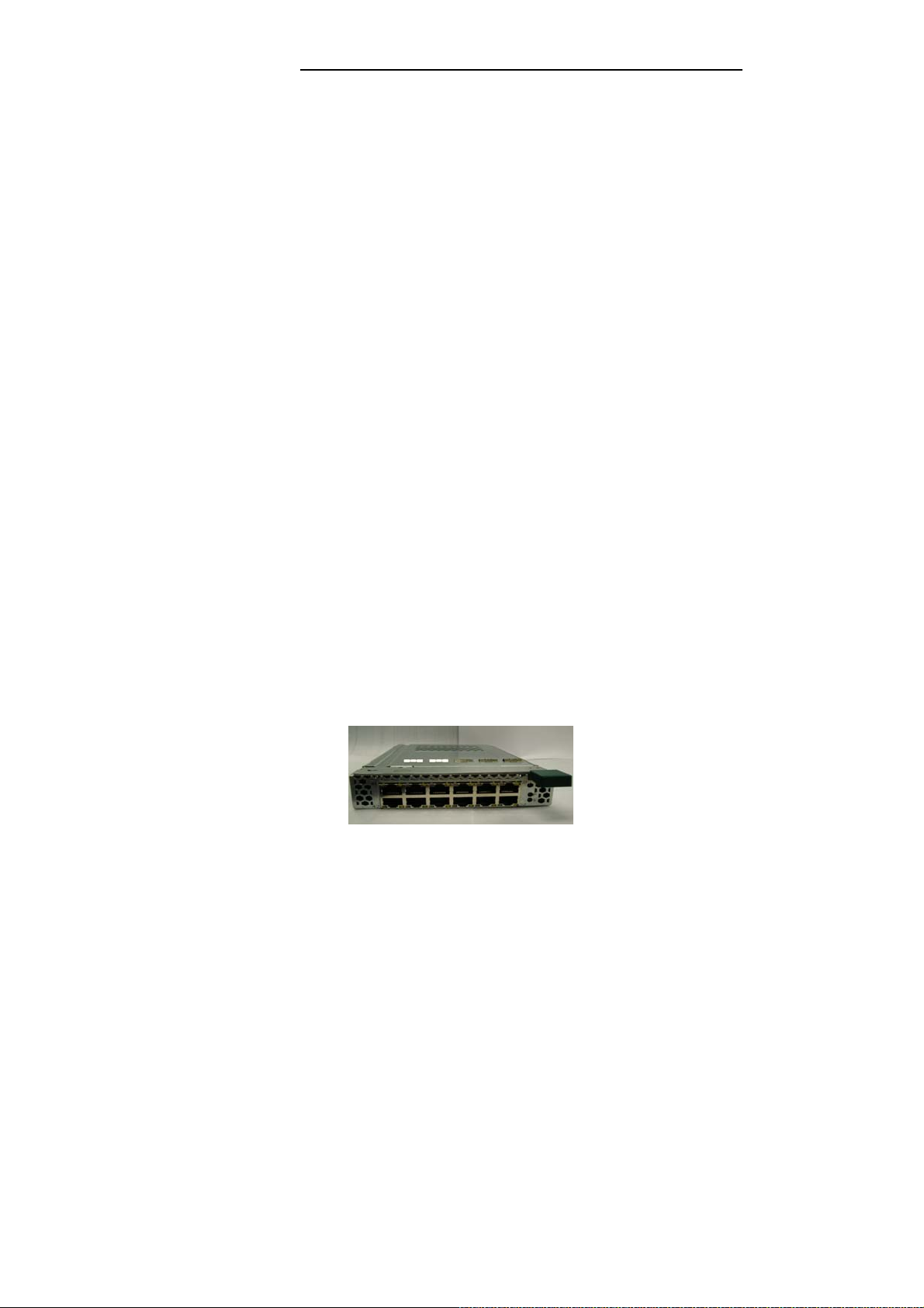
The following figure illustrates the PRIMERGY BX600:
Figure 1-1. PRIMERGY BX600 IBP Module Front Panel
12
Intelligent Blade Panel Module
Page 14

Features of the IBP Module Introduction
2.1 Features of the IBP Module
The IBP provides a wide range of advanced performance-enhancing features. Multicast
filtering provides support for real-time network applications. Flow control eliminates the loss of
packets due to bottlenecks caused by port saturation. And broadcast storm suppression
prevents broadcast traffic storms from engulfing the network. Some of the management
features are briefly described below.
Head of Line Blocking
Head of Line (HOL) blocking results in traffic delays and frame loss caused by traffic competing
for the same egress port resources. HOL blocking queues packets, and the packets at the
head of the queue are forwarded before packets at the end of the queue.
Flow Control Support (IEEE 802.3X)
Flow control enables lower speed devices to communicate with higher speed devices, by
requesting that the higher speed device refrains from sending packets. Transmissions are
temporarily halted to prevent buffer overflows.
Back Pressure Support
On half-duplex links, the receiving port prevents buffer overflows by occupying the link so that it
is unavailable for additional traffic.
Jumbo Frames Support
Jumbo frames are frames with an MTU size of up to 9K bytes, and better utilize the network by
transporting the same data using less frames. The main benefits of this facility are reduced
transmission overhead, and reduced host processing overhead. Less frames leads to less I/O
interrupts. This facility is typically used for server-to-server transfers.
MDI/MDIX Support
The IBP Module automatically detects whether the cable connected to an RJ-45 port is crossed
or straight through. Standard wiring for end stations is Media-Dependent Interface (MDI) and
the standard wiring for hubs and switches is known as Media-Dependent Interface with
Crossover (MDIX).
Auto Negotiation
Auto negotiation allows an IBP Module to advertise modes of operation. The auto negotiation
function provides the means to exchange information between two devices that share a
point-to-point link segment, and to automatically configure both devices to take maximum
advantage of their transmission capabilities.
2.1.1 MAC Address Supported Features
MAC Address Capacity Support
The IBP Module supports up to 16K MAC addresses. The IBP Module reserves specific MAC
addresses for system use.
Static MAC Entries
MAC entries can be manually entered in the Bridging Table, as an alternative to learning them
13
Intelligent Blade Panel Module
Page 15

Features of the IBP Module Introduction
from incoming frames. These user-defined entries are not subject to aging, and are preserved
across resets and reboots.
Self-Learning MAC Addresses
The IBP Module enables automatic MAC address learning from incoming packets. The MAC
addresses are stored in the Bridging Table.
Automatic Aging for MAC Addresses
MAC addresses from which no traffic is received for a given period are aged out. This prevents
the Bridging Table from overflowing.
Port Security
Port security prevents unauthorized users from accessing your network. It allows each port to
learn, or be assigned, a list of MAC addresses for devices authorized to access the network
through that port. Any packet received on the port must have a source address that appears in
the authorized list, otherwise it will be dropped. Port security is disabled on all ports by default,
but can be enabled on a per-port basis.
MAC Multicast Support
Multicast service is a limited broadcast service, which allows one-to-many and many-to-many
connections for information distribution. Layer 2 Multicast service is where a single frame is
addressed to a specific Multicast address, from where copies of the frame are transmitted to
the relevant ports.
2.1.2 Layer 2 Features
IGMP Snooping
IGMP Snooping examines IGMP frame contents, when they are forwarded by the IBP
Module from work stations to an upstream Multicast router. From the frame, the IBP Module
identifies work stations configured for Multicast sessions, and which Multicast routers are
sending Multicast frames.
Broadcast Storm Control
Storm Control enables limiting the amount of Multicast and Broadcast frames accepted and
forwarded by the IBP Module. When Layer 2 frames are forwarded, Broadcast and Multicast
frames are flooded to all ports on the relevant VLAN. This occupies bandwidth, and loads all
nodes connected on all ports.
VLAN Transparency Supported Features
The IBP supports VLAN transparency feature. All packets will be forwarded without any
modifications as they are received.
Link Aggregation
One Aggregated Links may be defined, with up to 8 member ports, to form a single Link
Aggregated Group (LAG). This enables:
• Fault tolerance protection from physical link disruption
• Higher bandwidth connections
• Improved bandwidth granularity
• High bandwidth server connectivity
LAG is composed of ports with the same speed, set to full-duplex operation.
14
Intelligent Blade Panel Module
Page 16

Features of the IBP Module Introduction
Uplink Set Support
Uplink Sets are used to define the external connection. An “Uplink Set” is defined as a set of 1
to n external (uplink) ports, which is used in port group definitions to connect a group of server
blades to the customer’s LAN. All members of a Uplink Set will form a LAG.
Port Group Support
Port Group feature is supported on IBP. Port Groups combine several internal ports into a
group. Up to 30 groups are available for IBP. Each Port Group could be combined with a uplink
set to be as its external connection. Packets only are forwarding within the same group.
VLAN Port Group Support
VLAN Port Group feature is used to define groups on VLAN basis, which are sharing the same
Uplink Set. Up to 30 groups are available for IBP. Packets received on internal ports should be
untagged packets, and the packets egress on uplink port should be tagged with the VLAN Port
Group’s VLAN IDs.
Within the set of VLAN Port Groups sharing the same Uplink Set one VLAN can optionally be
defined as “native VLAN”. This changes the tagging behavior at the uplink port for this native
VLAN ID. Incoming untagged packets tagged with the native VLAN Id and forwarded to all the
downlinks of this VLAN group. Incoming packets tagged with the native VLAN ID are dropped.
Service VLAN & Service LAN Support
Service VLAN & Service LAN are supported in IBP to provide dedicated ports for handling
specific VLAN tagged packets. The packets with the same VLAN will be forwarded within the
members. Their operations are very similar but in Service LAN, the tagged of packet egress on
the uplink ports will be stripped and send as untagged packet. The members of the Service
LAN & Service VLAN can be overlapped with the members of port group or VLAN Port group
with different VLAN ID.
Port Backup Support
Port Backup feature is supported on IBP for redundant uplink ports. Two aggregation groups
are created automatically as the Port Group is created. One of the aggregation groups are
defined as active aggregation link, and the other is defined as backup aggregation group. As
the active aggregation group is link down, the backup aggregation group will be activated for
transmittion. After the active aggregation group is link up again, the backup aggregation group
will be deactivated.
Failover Propogation Support
Blade Server has a dual-port network interface controller, and it realizes the redundant LAN
ports in case of using NIC management program with LAN teaming function. In order to
improve the switching time and realize the “rapid” fail-over of redundant LAN ports, Failover
Propogation feature is introduced in IBP for uplink ports to speed up the switching of the
redundant LAN ports.
Link Aggregation and LACP
LACP uses peer exchanges across links to determine, on an ongoing basis, the aggregation
capability of various links, and continuously provides the maximum level of aggregation
capability achievable between a given pair of systems. LACP automatically determines,
15
Intelligent Blade Panel Module
Page 17

Features of the IBP Module Introduction
configures, binds and monitors the port binding to aggregators within the system.
BootP and DHCP Clients
DHCP enables additional setup parameters to be received from a network server upon system
startup. DHCP service is an on-going process. DHCP is an extension to BootP. For more
information on DHCP, see "Defining DHCP IP Interface Parameters".
2.1.3 IBP Module Management Features
The Intelligent Blade Panel can either be managed through the console port (out-of-band
management) or through the network (in-band management) with SNMP, TELNET or HTTP
protocols.
Various Files of Management Operation:
z There are three types of files for the Intelligent Blade Panel:
Configuration Files: The file stores system configuration information
Operation Code: Executed after system boot-up, also known as Run Time Image
BootRom Image: The images brought up by loader when power up. Also known as
POST (Power On Self-Test)
z Due to the size of flash memory, the Intelligent Blade Panel supports only two copies for
Configuration files and Operation Code respectively, but only one copy for BootRom
Image.
Duplication of Management file
The Intelligent Blade Panel can copy those three types of files in three different ways.
1. Local file to local file copy: The Intelligent Blade Panel can copy an existed local
Configuration File to another local file. Copy exited local Operation Code to another
local file is not permitted.
2. Remote TFTP Server to Local file copy: The Intelligent Blade Panel can support to
download Configuration File or Operation Code from remote server to local file.
3. Local file to remote server: The Intelligent Blade Panel can support to upload an existed
local Configuration File to the remote server.
4. Running Config to local file copy
5. Running Config to remote TFTP server
6. Local file to Running Config copy
7. Remote TFTP server to Running Config copy
Select Start-up Files
Users can select one of two copies for Configuration Files and Operation Codes as start-up file
which is used as default bootup configuration and execution image, And the other copy of
Configuration File and Operation Code will be used for backup.
Save Configuration as file
Users can save the running configuration as a file for future use. This newly saved
configuration file can be selected as start-up file later on. Or users can upload this saved
configuration to the remote server for backup.
16
Intelligent Blade Panel Module
Page 18

Features of the IBP Module Introduction
Provision
The Intelligent Blade Panel allows users to select the Configuration files to configure the
system. There are two timings to configure system: Start-up and Run time.
Start-up: Select the Configuration File for start-up purpose.
Run time: Users can choose a new configuration file to reconfigure the system while system
running, without rebooting the system. This function is available for CLI only.
SNMP Alarms and Trap Logs
The system logs events with severity codes and timestamps. Events are sent as SNMP traps
to a Trap Recipient List.
SNMP Version 1,Version 2, and Version 3
Simple Network Management Protocol (SNMP) over the UDP/IP protocol. To control access to
the system, a list of community entries is defined, each of which consists of a community string
and its access privileges. There are 2 levels of SNMP security read-only and read-write.
Web Based Management
With web based management, the system can be managed from any web browser. The
system contains an Embedded Web Server (EWS), which serves HTML pages, through which
the system can be monitored and configured. The system internally converts web-based input
into configuration commands, MIB variable settings and other management-related settings.
Configuration File Download and Upload
The IBP Module configuration is stored in a configuration file. The Configuration file includes
both system wide and port specific IBP Module configuration. The system can display
configuration files in the form of a collection of CLI commands, which are stored and
manipulated as text files.
TFTP Trivial File Transfer Protocol
The IBP Module supports boot image, software and configuration upload/download via TFTP.
Remote Monitoring
Remote Monitoring (RMON) is an extension to SNMP, which provides comprehensive network
traffic monitoring capabilities (as opposed to SNMP which allows network IBP Module
management and monitoring). RMON is a standard MIB that defines current and historical
MAC-layer statistics and control objects, allowing real-time information to be captured across
the entire network.
Command Line Interface
Command Line Interface (CLI) syntax and semantics conform as much as possible to common
industry practice. CLI is composed of mandatory and optional elements. The CLI interpreter
provides command and keyword completion to assist user and shorten typing.
Syslog
Syslog is a protocol that allows event notifications to be sent to a set of remote servers, where
they can be stored, examined and acted upon. Multiple mechanisms are implemented to send
notification of significant events in real time, and keep a record of these events for after-the-fact
usage.
SNTP
The Simple Network Time Protocol (SNTP) assures accurate network IBP Module clock time
synchronization up to the millisecond. Time synchronization is performed by a network SNTP
server. Time sources are established by Stratums. Stratums define the distance from the
17
Intelligent Blade Panel Module
Page 19

Features of the IBP Module Introduction
reference clock. The higher the stratum (where zero is the highest), the more accurate the
clock.
2.1.4 Security Feature
SSL
Secure Socket Layer (SSL) is an application-level protocol that enables secure transactions of
data through privacy, authentication, and data integrity. It relies upon certificates and public
and private keys. SSL version 3 and TLS version 1 are currently supported.
Port Based Authentication (802.1x)
Port based authentication enables authenticating system users on a per-port basis via an
external server. Only authenticated and approved system users can transmit and receive data.
Ports are authenticated via the Remote Authentication Dial In User Service (RADIUS) server
using the Extensible Authentication Protocol (EAP).
Locked Port Support
Locked Port increases network security by limiting access on a specific port only to users with
specific MAC addresses. These addresses are either manually defined or learned on that port.
When a frame is seen on a locked port, and the frame source MAC address is not tied to that
port, the protection mechanism is invoked.
RADIUS Client
RADIUS is a client/server-based protocol. A RADIUS server maintains a user database, which
contains per-user authentication information, such as user name, password and accounting
information. For more information, see "Configuring RADIUS Global Parameters".
SSH
Secure Shell (SSH) is a protocol that provides a secure, remote connection to an IBP Module.
SSH version 1 and version 2 are currently supported. The SSH server feature enables an SSH
client to establish a secure, encrypted connection with a IBP Module. This connection provides
functionality that is similar to an inbound telnet connection. SSH uses RSA Public Key
cryptography for IBP Module connections and authentication.
TACACS+
TACACS+ provides centralized security for validation of users accessing the IBP Module.
TACACS+ provides a centralized user management system, while still retaining consistency
with RADIUS and other authentication processes.
18
Intelligent Blade Panel Module
Page 20

System LED
There is one IBP Module system LED with dual functions, controlled by MMB for error status
reporting and blade identification. Different flashing frequencies are used to indicate the
different functions. There are two functions, identification and error reporting, with identification
having a higher priority than error reporting.
NOTE: If there is an error and the identification function is activated, the LED still functions as
an identification LED. The LED can only be disabled by the MMB with a 255 seconds timeout. If
an error is happening, the LED for error reporting will always be flashing and cannot be turn off.
The following table describes the system LED indications.
Features and Benefits Introduction
2.2 Description of Hardware
IBP Module Port Configurations
PRIMERGY BX600 Front Panel Port Description
The PRIMERGY BX600 IBP Module contains 12 Gigabit Ethernet ports for connecting to the
network and 30 Gigabit Ethernet ports for connecting PRIMERGY BX600 Blade Server
management MMB modules.
The 12 Gigabit Ethernet ports can operate at 10, 100 or 1000 Mbps. These ports support auto
negotiation, duplex mode (Half or Full duplex), and flow control. The 30 Gigabit Ethernet ports
that connect to server modules can only operate at 1000 Mbps, full-duplex. These 30 ports also
support flow control.
The following figure illustrates the PRIMERGY BX600 IBP front panel.
Figure 1. PRIMERGY BX600 IBP Front Panel
2.2.1 Ethernet Ports
Up-link Ports
12 external RJ-45 ports support IEEE 802.3x auto-negotiation of speed, duplex mode, and flow
control. Each port can operate at 10 Mbps, 100 Mbps and 1000 Mbps, full and half duplex, and
control the data stream to prevent buffers from overflowing. The up-link ports can be connected
to other IEEE 802.3ab 1000BASE-T compliant devices up to 100 m (328 ft.) away using
Category 5 twisted-pair cable. These ports also feature automatic MDI/MDI-X operation, so
you can use straight-through cables for all connections. These up-link ports are named g31 –
g42 in the configuration interface.
Note – Note that when using auto-negotiation, the speed, transmission mode and flow control
19
Intelligent Blade Panel Module
Page 21

Features of the IBP Module Introduction
can be automatically set if this feature is also supported by the attached device. Otherwise,
these items can be manually configured for any connection.
Note – Auto-negotiation must be enabled for automatic MDI/MDI-X pin-out configuration.
Internal Ports
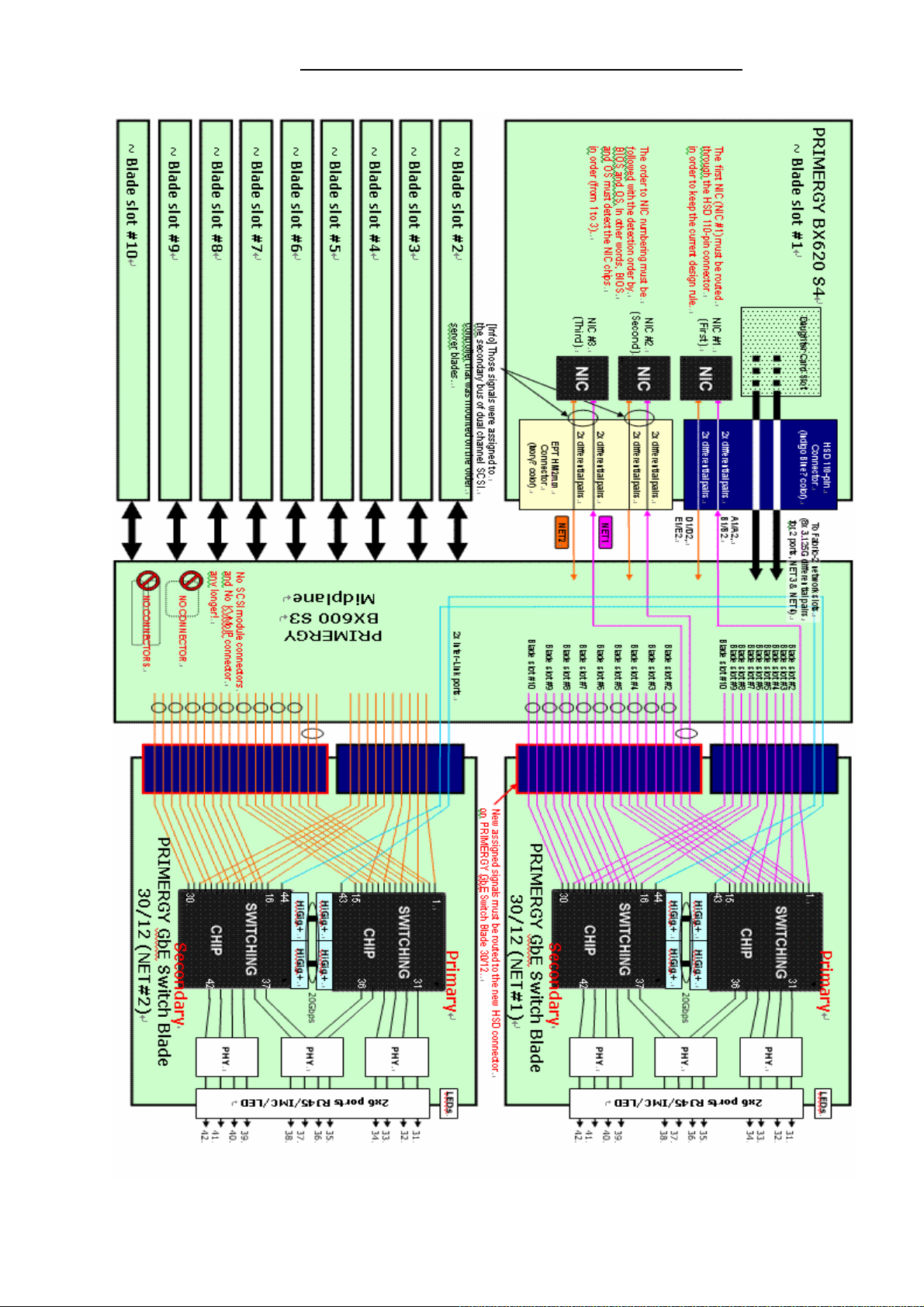
The IBP also includes 30 internal 1000BASE-X Gigabit Ethernet ports that connect to the
server blades in the chassis. These ports are fixed at 1000 Mbps, full duplex. The internal ports
are named g1 – g30 in the configuration interface. The 30 internal ports connect with server
blade as following diagram.
20
Intelligent Blade Panel Module
Page 22
Features of the IBP Module Introduction
21
Intelligent Blade Panel Module
Page 23

Features of the IBP Module Introduction
PRIMERGY GbE Switch Blade 30/12 Internal Ports List
PRIMERGY BX620
S4 Nic No.
Blade No 1 Nic 1 Net 1 Port 1 Blade No 6 Nic 1 Net 1 Port 16
Blade No 1 Nic 2 Net 2 Port 1 Blade No 6 Nic 2 Net 2 Port 16
Blade No 1 Nic 3 Net 1 Port 2 Blade No 6 Nic 3 Net 1 Port 17
Blade No 1 Nic 4 Net 2 Port 2 Blade No 6 Nic 4 Net 2 Port 17
Blade No 1 Nic 5 Net 1 Port 3 Blade No 6 Nic 5 Net 1 Port 18
Blade No 1 Nic 6 Net 2 Port 3 Blade No 6 Nic 6 Net 2 Port 18
Blade No 2 Nic 1 Net 1 Port 4 Blade No 7 Nic 1 Net 1 Port 19
Blade No 2 Nic 2 Net 2 Port 4 Blade No 7 Nic 2 Net 2 Port 19
Blade No 2 Nic 3 Net 1 Port 5 Blade No 7 Nic 3 Net 1 Port 20
Blade No 2 Nic 4 Net 2 Port 5 Blade No 7 Nic 4 Net 2 Port 20
Blade No 2 Nic 5 Net 1 Port 6 Blade No 7 Nic 5 Net 1 Port 21
Blade No 2 Nic 6 Net 2 Port 6 Blade No 7 Nic 6 Net 2 Port 21
Blade No 3 Nic 1 Net 1 Port 7 Blade No 8 Nic 1 Net 1 Port 22
I/O Switch
Blade Module.
Internal
Ports Mapping
PRIMERGY BX620
S4 Nic No.
I/O Switch
Blade Module.
Internal
Ports Mapping
Blade No 3 Nic 2 Net 2 Port 7 Blade No 8 Nic 2 Net 2 Port 22
Blade No 3 Nic 3 Net 1 Port 8 Blade No 8 Nic 3 Net 1 Port 23
Blade No 3 Nic 4 Net 2 Port 8 Blade No 8 Nic 4 Net 2 Port 23
Blade No 3 Nic 5 Net 1 Port 9 Blade No 8 Nic 5 Net 1 Port 24
Blade No 3 Nic 6 Net 2 Port 9 Blade No 8 Nic 6 Net 2 Port 24
Blade No 4 Nic 1 Net 1 Port 10 Blade No 9 Nic 1 Net 1 Port 25
Blade No 4 Nic 2 Net 2 Port 10 Blade No 9 Nic 2 Net 2 Port 25
Blade No 4 Nic 3 Net 1 Port 11 Blade No 9 Nic 3 Net 1 Port 26
Blade No 4 Nic 4 Net 2 Port 11 Blade No 9 Nic 4 Net 2 Port 26
Blade No 4 Nic 5 Net 1 Port 12 Blade No 9 Nic 5 Net 1 Port 27
Blade No 4 Nic 6 Net 2 Port 12 Blade No 9 Nic 6 Net 2 Port 27
Blade No 5 Nic 1 Net 1 Port 13 Blade No 10 Nic 1 Net 1 Port 28
Blade No 5 Nic 2 Net 2 Port 13 Blade No 10 Nic 2 Net 2 Port 28
Blade No 5 Nic 3 Net 1 Port 14 Blade No 10 Nic 3 Net 1 Port 29
Blade No 5 Nic 4 Net 2 Port 14 Blade No 10 Nic 4 Net 2 Port 29
Blade No 5 Nic 5 Net 1 Port 15 Blade No 10 Nic 5 Net 1 Port 30
Blade No 5 Nic 6 Net 2 Port 15 Blade No 10 Nic 6 Net 2 Port 30
22
Intelligent Blade Panel Module
Page 24

Features of the IBP Module Introduction
2.2.2 Status of LEDs
The front panel contains light emitting diodes (LED) that indicate the status of links, and IBP
diagnostics.
Port LEDs
Each of uplink port has two LED indicators.
One Gbe Port LED definition:
LED Color Function
LED-A
(Speed)
LED-B
(Link/Activity)
Orange Port Link at 1000 Mbps
Green Port Link at 100 Mbps
Off Port Link at 10 Mbps
Yellow Network Link
Yellow Blink Network Activity
Off No Network Link or port disable
Power, Manage of LED indicator:
LED Color Function
TOP Green Power LED
BUTTOM
Green Identify LED
System LED
There is one IBP Module system LED with dual functions, controlled by MMB for error status
reporting and blade identification. Different flashing frequencies are used to indicate the
different functions. There are two functions, identification and error reporting, with identification
having a higher priority than error reporting.
NOTE: If there is an error and the identification function is activated, the LED still functions as
an identification LED. The LED can only be disabled by the MMB with a 255 seconds timeout. If
an error is happening, the LED for error reporting will always be flashing and cannot be turn off.
The following table describes the system LED indications.
2.3 Features and Benefits
2.3.1 Connectivity
l
30 internal Gigabit ports for easy network integration of your server cards
l
l
23
12
external 1000BASE-T Gigabit ports for uplinking to the corporate network
Support for auto MDI/MDI-X on external ports allows any connections to be made with
Intelligent Blade Panel Module
Page 25

Features of the IBP Module Introduction
straight-through cable (with auto-negotiation enabled)
l
Auto-negotiation enables each port to automatically select the optimum speed (10, 100
or 1000 Mbps) and communication mode (half or full duplex) if this feature is supported
by the attached device; otherwise the port can be configured manually
l
IEEE 802.3ab Gigabit Ethernet compliance ensures compatibility with
standards-based
2.3.2 Performance
l
Transparent bridging
l
Aggregate bandwidth up to
l
Switching Table with
l
Filtering and forwarding at line speed
l
Non-blocking switching architecture
2.3.3 Management
network cards and switches from any vendor
12
Gbps
16K
MAC address entries
l
Telnet, SNMP/RMON and Web-based interface
l
Multicast Switching based on IGMP (Internet Group Management Protocol) Snooping and
Multicast Filtering
l
Broadcast storm suppression
l
Link aggregaton
l
Management access security provided with username/password, and SNMP community
names
24
Intelligent Blade Panel Module
Page 26

p
l
Telnet, SNMP/RMON and Web-based interface
l
Multicast Switching based on IGMP (Internet Group Management Protocol) Snooping and
Multicast Filtering
l
Broadcast storm suppression
l
Link aggregaton
l
Management access security provided with username/password, and SNMP community
names
Notational Conventions
2.4
Notational Conventions
Introduction
The meanings of the symbols and fonts used in this manual are as follows:
I
CAUTION!
!
“Quotation marks”
Pay particular attention to texts marked with this symbol.
to
Failure
system,
indicate names of chapters and terms that are being
em
This symbol is followed by supplementary information, remarks
and
observe this warning endangers your life, destroys th
hasized
tips.
25
Intelligent Blade Panel Module
Page 27

Ta r g e t Group
2.5
Target Group
Introduction
This manual is intended for those responsible for installing and configuring network
connections. This manual contains all the information required to configure the IBP.
26
Intelligent Blade Panel Module
Page 28

Technical Data
CSA
950
2.6
Technical Data
Introduction
Electrical data
Operating voltage
Maximum current
National
Product safety
Electromagnetic compatibility
and international standards
Interference emission
Harmonic current
flicker
Interference immunity
+12 VDC @ 3 A max
11 A max @ 3.3 VDC
IEC 60950 / EN 60950 / UL 1950,
22.2 No.
FCC class A
Industry Canada class A
EN60005-2
EN60005-3
VCCI class A
AS / NZS 3548 class A
EN 55022
EN 6100-3-2 JEIDA
class
A
CE certification to
EU directives:
Dimensions
Length
Height
242 mm
110 mm
EN 61000-3-3
EN 55024,
73/23/EEC (low voltage directive)
89/336/EEC
Compatibility )
-
-
(Electromagnetic
27
Intelligent Blade Panel Module
Page 29

Technical Data
Introduction
Enviro nmental conditions
Environment class 3K2
Environment class 2K2
Temperature:
– Operating (3K2)
– Transport (2K2)
DIN IEC 721 part 3-3
DIN IEC 721 part 3-2
0 °C .... 50 °C
-40 °C .... 70 °C
Humidity 10 ... 90%
Condensation while operating must be avoided.
28
Intelligent Blade Panel Module
Page 30

Introduction to
IBP Network Planning
3 Network Planning
3.1
Introduction to
The
Intelligent Blade Panel M
connecting
administrative effort and network skills required to connect to the network are minimized. The
number and type of configuration options on the
complexity and to minimize the impact on upstream networking devices.
multi-linked
becomes as easy as connecting a single server to the network.
the PRIMERGY BX600 Blade Server systems to the network infrastructure. The
The
IBP
requires basic administration tasks similar to those required to connect a single
server to the network. Connecting the Blade Center with up to ten server blades
IBP
odule (IBP) provides a simple Ethernet interface option for
IBP
are restricted to reduce the initial setup
The default network configuration of the
Area
Network (VLAN). All of the uplink ports in each Port Group are aggregated together into a
IBP is
consists of a single, untagged Virtual Local
static Link Aggregation Group (LAG, or trunk group), which is fully compatible with Cisco Ether
Channel
prevent network loops, since the uplink ports act as a single link.
technology. This configuration eliminates the need for Spanning Tree Protocol to
The
IBP
provides improved network reliability. All of the uplink ports in each Port Group
participates
in a
static LAG, so if a link fails, the existing traffic is redirected to the other links.
The
IBP
(10/100/1000
software permits the copper TX uplink ports to auto-negotiate the speed
Mbps), duplex (full/half) and flow-control settings of each link (the default set- ting).
You can also fix these port characteristics to specified values. All of the uplink ports in each Port
Group must be configured to the same port characteristics.
With Network Adaptor Teaming configured on the server blade Ethernet NIC, the servers
can maintain redundant links to multiple
enhanced
when
ware
reliability. The L2 Failover option allows the
all of its external uplinks are inactive. This causes the Network Adaptor Teaming soft-
to
failover to the other
IBP
(s) in the Blade Server Chassis.
IBP
within the Blade Sever chassis to provide
IBP to
disable the server-blade ports
29
Intelligent Blade Panel Module
Page 31

The
IBP
connects server boards installed inside the system to a common switch fabric, and
also provides three external ports for uplinking to external IEEE 802.3ab compliant devices. For
most applications, the external ports on the
IBP
will be connected to other switches in the
network backbone.
Connecting to 1000BASE-T Devices
Making Network Connections
4 Making Network Connections
The
IBP
connects server boards installed inside the system to a common switch fabric, and
also provides three external ports for uplinking to external IEEE 802.3ab compliant devices. For
most applications, the external ports on the
network backbone.
4.1
Connecting to 1000BASE-T Devices
The data ports on the
IBP
operate at 10 Mbps, 100 Mbps, and 1000 Mbps, full and half duplex,
with support for auto-negotiation of speed, duplex mode and flow control. Yo u can connect any
data port on the
IBP to
any server or workstation, or uplink to a network device such as another
switch or a router. The 1000BASE-T standard uses four pairs of Category 5 twisted-pair cable
for connections up to a maximum length of 100 m (328 feet).
For 1000 Mbps operation, you should first test the cable installation for IEEE 802.3ab
1000BASE-T compliance. See “1000BASE-T Cable Requirements” on page 34 for more
information.
IBP
will be connected to other switches in the
1. Prepare the devices you wish to network. For 1000 Mbps operation, make sure that
servers and workstations have installed 1000BASE-T network interface cards. Other
network devices should have RJ-45 ports that comply with the IEEE 802.3ab 1000BASE-T
standard.
2. Prepare shielded or unshielded twisted-pair cables (straight-through or crossover) with
RJ-45 plugs at both ends. Use 100-ohm Category 5 (Category 5e or better is
recommended) cable for 1000 Mbps Gigabit Ethernet connections.
3. Connect one end of the cable to the RJ-45 port on the other device, and the other end to
any available RJ-45 port on the
plug clicks into position to ensure that it is properly seated.
IBP.
When inserting an RJ-45 plug, be sure the tab on the
30
Intelligent Blade Panel Module
Page 32

1000BASE-T Cable Requirements
Making Network Connections
Do not plug a phone jack connector into any RJ-45 port. This may
damage the
connectors that conform with FCC standards.
IBP.
Instead, use only twisted-pair cables with RJ-45
For 1000 Mbps operation, all four wire pairs in the cable must be connected. When
auto-negotiation is enabled, the 1000BASE-T ports support the auto MDI/MDI-X feature,
which means that at any operating speed (10, 100, or 1000 Mbps), either straight-through
or crossover cables can be used to connect to any server, workstation, or other network
device. Make sure each twisted-pair cable does not exceed
100 meters (328 feet). (Note that auto-negotiation must be enabled to support auto
MDI/MDI-X.)
4.2
1000BASE-T Cable Requirements
All Category 5 UTP cables that are used for 100BASE-TX connections should also work for
1000BASE-T, providing that all four wire pairs are connected. However, it is recommended that
for all critical connections, or any new cable installations, Category 5e (enhanced Category 5)
cable should be used. The Category 5e specification includes test parameters that are only
recommenda- tions for Category 5. Therefore, the first step in preparing existing Category 5
cabling
complies with the IEEE 802.3ab standards.
for running 1000BASE-T is a simple test of the cable installation to be sure that it
4.2.1 Cable Testing for Existing Category 5 Cable
Installed Category 5 cabling must pass tests for Attenuation, Near-End Crosstalk (NEXT), and
Far-End Crosstalk (FEXT). This cable testing infor- mation is specified in the
ANSI/TIA/EIA-TSB-67 standard. Additionally, cables must also pass test parameters for Return
Loss and Equal-Level Far-End Crosstalk (ELFEXT). These tests are specified in the
ANSI/TIA/EIA-TSB-95Bulletin, “The Additional Transmission Performance Guidelines for 100
Ohm 4- Pair Category 5 Cabling”.
Note that when testing your cable installation, be sure to include all patch cables between
and end devices.
IBP
31
Intelligent Blade Panel Module
Page 33

1000BASE-T Pin Assignments
Making Network Connections
4.2.2 Adjusting Existing Category 5 Cabling for 1000BASE-T
If your existing Category 5 installation does not meet one of the test parameters for
1000BASE-T, there are basically three measures that can be applied to try and correct the
problem:
1. Replace any Category 5 patch cables with high-performance Category 5e cables.
2. Reduce the number of connectors used in the link.
3. Reconnect some of the connectors in the link.
4.3
1000BASE-T ports support automatic MDI/MDI-X operation, so you can use straight-through
cables for all network connections to PCs or servers, or to other switches. (Auto-negotiation
must be enabled to support auto MDI/MDI-X.)
The table below shows the 1000BASE-T MDI and MDI-X port pinouts. These ports require
that all four pairs of wires be connected. Note that for 1000BASE-T operation, all four pairs of
wires are used for both transmit and receive.
1000BASE-T Pin Assignments
Use 100-ohm Category 5 or 5e unshielded twisted-pair (UTP) or shielded twisted-pair (STP)
cable for 1000BASE-T connections. Also be sure that the length of any twisted-pair
connection does not exceed 100 meters (328 feet).
32
Intelligent Blade Panel Module
Page 34

Overview Configuration the IBP Module
5 Configuration the IBP Module
This section contains information about IBP unpacking, installation, and cable connections.
5.1 Overview
The IBP Module is inserted in the PRIMERGY BX600 Blade Server which is a modular server
system that can integrates up to 10 processor blades and four IBP Modules.
Package Contents
While unpacking the IBP Module, ensure that the following items are included:
• The IBP Module
• Documentation CD
Unpacking the IBP Module
To unpack the IBP Module:
NOTE: Before unpacking the IBP Module, inspect the package and report any evidence of
damage immediately.
NOTE: An ESD strap is not provided, however it is recommended to wear one for the following
procedure.
1 Open the container.
2 Carefully remove the IBP Module from the container and place it on a secure and clean
surface.
3 Remove all packing material.
4 Inspect the IBP Module for damage. Report any damage immediately.
NOTE: The illustrations in this document might differ slightly from actual Blade Panel and
chassis.
33
Intelligent Blade Panel Module
Page 35

Connecting the IBP Module Configuration the IBP Module
5.2 Connecting the IBP Module
Before configuring the IBP Module, PRIMERGY BX600 Blade Server console port must be
connected to the IBP Module. To connect PRIMERGY BX600 Blade Server console port to the
IBP Module, perform the following:
1. Mount the IBP Module.
On the console monitor the MMB application displays a login screen.
The IBP Module bootup screen is displayed.
Welcome to Management Blade 1.70D
<Username>:
+-----------------------------------------------------------------------------+
| Console Menu |
+-----------------------------------------------------------------------------+
(1) Management Agent
(2) Emergency Management Port
(3) Console Redirection
(4) TFTP update
(5) Logout
(6) Reboot Management Blade
(7) System Information Dump
Enter selection: 5
+-----------------------------------------------------------------------------+
| Logout!!! |
+-----------------------------------------------------------------------------+
ATE0
ATE0
2. Enter the provide and password. The console menu is displayed.
Welcome to Management Blade 1.70D
<Username>:root
<Password>:****
+-----------------------------------------------------------------------------+
| Console Menu |
+-----------------------------------------------------------------------------+
(1) Management Agent
(2) Emergency Management Port
(3) Console Redirection
(4) TFTP update
34
Intelligent Blade Panel Module
Page 36

Connecting the IBP Module Configuration the IBP Module
(5) Logout
(6) Reboot Management Blade
(7) System Information Dump
Enter selection: 3
3. Select (3) Console Redirection. The Console Redirection Table is displayed.
+-----------------------------------------------------------------------------+
| Console Redirection Table |
+-----------------------------------------------------------------------------+
(1) Console Redirect Server Blade
(2) Console Redirect Switch Blade
(3) Set Return Hotkey , Ctrl+(a character) : Q
Enter selection or type (0) to quit: 2
+-----------------------------------------------------------------------------+
| Console Redirect Switch Blade |
+-----------------------------------------------------------------------------+
Enter selection or type (0) to quit: 0
4. Select (2) Console Redirection Switch Blade
+-----------------------------------------------------------------------------+
| Console Redirection Table |
+-----------------------------------------------------------------------------+
(1) Console Redirect Server Blade
(2) Console Redirect Switch Blade
(3) Set Return Hotkey , Ctrl+(a character) : Q
Enter selection or type (0) to quit: 2
+-----------------------------------------------------------------------------+
| Console Redirect Switch Blade |
+-----------------------------------------------------------------------------+
(1) Console Redirect Switch Blade_1
Enter selection or type (0) to quit: 1
Press <Ctrl+Q> Return Console Menu
35
Intelligent Blade Panel Module
Page 37

Start up and Configuration the IBP Module Configuration the IBP Module
5.3 Start up and Configuration the IBP Module
It’s important to understand the IBP Module architecture when configuring the IBP Module. The
IBP Module has two types of ports. One type is for interfacing the IBP Module with PRIMERGY
BX600 Blade Server, and the other type are regular Ethernet ports used for connecting
PRIMERGY BX600 Blade Server to the network.
The IBP Module module is connected to PRIMERGY BX600 Blade Server (Management
Board) MMB through 30 internal ports called the Internal Ports. The maximum link speed
through the Internal Ports is 1 Gigabit per port. The port configuration ID’s are g1 to g30. To
connect the IBP Module to the network there are 12 PHY based ports called the External ports.
The external 12 ports are 10/100/1000 Base-T Ethernet ports. The port configuration ID’s are
g31 to g42.
The default configuration of the internal and external ports are as follows:
Table 4-1. Port Default Settings
Figure 4-1. Installation and Configuration Flow
36
Intelligent Blade Panel Module
Page 38

Configuring the Terminal Configuration the IBP Module
5.4 Configuring the Terminal
To configure the device, the station must be running terminal emulation software. Ensure that
switch module is correctly mounted and is connected to the chassis serial port. Ensure that the
terminal emulation software is set as follows: Connect PRIMERGY BX600 Blade Server serial
port to the IBP Module.
NOTE:
1. The default data rate is 9600. No other data rate is required for initial configuration.
2. Sets the data format to 9600 baudrate 9600,8 data bits, 1 stop bit, and no parity.
3. Sets Flow Control to none.
4. Under Properties, select VT100 for Emulation mode.
5. Select Terminal keys for Function, Arrow, and Ctrl keys. Ensure that the setting is for
Terminal keys (not Windows keys).
For accessing IBP module from terminal perform following steps:
1. Connect your terminal to the serial port of the Chassis.
37
Intelligent Blade Panel Module
Page 39

Booting Device Configuration the IBP Module
2. Power up the Chassis and observe booting information (if Chassis is running press <Enter>
few times to ensure that terminal connection is successful).
5.5 Booting Device
• The device is delivered with a default configuration.
• The device is not configured with a default user name and password.
After connecting the PRIMERGY BX600 Blade Server serial port to the IBP Module,
When the IBP Module is connected to the local terminal, the device IBP Module goes through
Power On Self Test (POST). POST runs every time the device is initialized and checks
hardware components to determine if the device is fully operational before completely booting.
If a critical problem is detected, the program flow stops. If POST passes successfully, a valid
executable image is loaded into RAM. POST messages are displayed on the terminal and
indicate test success or failure.
As the device boots, the bootup test first counts the device memory availability and then
continues to boot. The following screen is an example of the displayed POST:
------------ Performing Power-On Self Tests (POST) --------------
System SDRAM Test..........…………….........PASS
CPU Self Test......................………………….PASS
UART Loopback Test.................……………..PASS
Flash Memory Initialize............……………….PASS
Flash Memory Checksum Test.........………...PASS
PCI Bus Initialize and Test........………………PASS
System Timer Test..................………………..PASS
---------------Power-On Self Test Completed---------------------------
The boot process runs approximately 60 seconds.
The auto-boot message displayed at the end of POST (see the last lines) indicates that no
problems were encountered during boot. During the BootROM Back Door Command Line
Interface can be used to run special procedures. To enter the BootROM Back Door CLI
menu, press <Ctrl-B> within the first two seconds after the auto-boot message is displayed. If
the system boot process is not interrupted by pressing <Ctrl-B>, the process continues
decompressing and loading the code into RAM. The code starts running from RAM and the list
of numbered system ports and their states (up or down) are displayed. After the device boots
successfully, a system prompt is displayed ((vty-0) #) which is used to configure the device.
However, before configuring the device, ensure that the latest software version is installed on
38
Intelligent Blade Panel Module
Page 40

Software Download Configuration the IBP Module
the device. If it is not the latest version, download and install the latest version. For more
information on downloading the latest version see the "Software Download"
5.6 Software Download
5.6.1 In BootROM Back Door CLI
Software Download Using Xmodem Protocol
The software download procedure is performed when a new version must be downloaded to
replace the corrupted files, update or upgrade the system software (system and boot images).
NOTE: The data rate cannot be changed.
To download software from the BootROM CLI:
1. From the BootROM CLI prompt input the following command: xmodem –rb <filename>
2. When using the HyperTerminal, click Transfer on the HyperTerminal Menu Bar.
3. In the Filename field, enter the file path for the file to be downloaded.
4. Ensure that the Xmodem protocol is selected in the Protocol field.
5. Press Send. The software is downloaded.
Erasing the Device Configuration
1. From the BootROM CLI prompt input the following command:
delete <configuration filename>
The following message is displayed:
Are you sure you want to delete <configuration filename> (y/n)?
2. Press Y. The following message is displayed.
Updating partition table, please wait ... Done
Image file <configuration filename> deleted.
3. Repeat the device initial configuration.
Boot Image Download
Loading a new boot image using xmodem protocol and programming it into the flash updates
the boot image. The boot image is loaded when the device is powered on. A user has no
control over the boot image copies. To download a boot image using xmodem protocol:
1. Ensure that the file to be downloaded is saved on the PC host (the img file).
2. Enter BootROM > dir -l command to verify which software version is currently running on
the device. The following is an example of the information that appears:
BootROM > dir -l
type zip def date version name
------------------------------------------------------------------------------loader none yes 2005/12/14 0.4 PRIMERGY BX600-l-0.4.1214.bin
bootrom gzip yes 2005/12/14 0.4 PRIMERGY BX600-b-0.4.1214.biz
runtime gzip yes 2005/01/10 0.5 PRIMERGY BX600-r-q-0.5.0110.biz
Total: 3 files.
3. From the BootROM CLI prompt input the following command: xmodem –rb <filename>
4. When using the HyperTerminal, click Transfer on the HyperTerminal Menu Bar.
5. In the Filename field, enter the file path for the file to be downloaded.
6. Ensure that the Xmodem protocol is selected in the Protocol field.
7. Press Send. The software is downloaded.
39
Intelligent Blade Panel Module
Page 41

Software Download Configuration the IBP Module
8. Enter the reset command. The following message is displayed:
BootROM > reset
Are you sure you want to reset the system (y/n)? y
System Resetting...
9. Enter y. The device reboots.
5.6.2 In Operation Code CLI
Software Download Through TFTP Server
This section contains instructions for downloading device software through a TFTP server. The
TFTP server must be configured before beginning to download the software.
System Image Download
The device boots and runs when decompressing the system image from the flash memory
area where a copy of the system image is stored. When a new image is downloaded, it is
saved in the other area allocated for the other system image copy. On the next boot, the device
will decompress and run the currently active system image unless chosen otherwise.
To download a system image through the TFTP server:
1. Ensure that an IP address is configured on one of the device ports and pings can be sent to
a TFTP server.
2. Make sure that the file to be downloaded is saved on the TFTP server (the img file).
3. Enter (vty-0) # show version command to verify which software version is currently
running on the device. The following is an example of the information that appears:
(vty-0) #show version
Unit1
Serial number :123456789
Hardware Version :1.0
Number of ports :16
Label Revision Number :123456789
Part Number :123456789
Machine Model :PRIMERGY BX600
Loader version :1.0
Operation code version :0.50
Boot rom version :1.0
4. Enter (vty-0) # whichboot command to verify which system image is currently active. The
following is an example of the information that appears:
(vty-0) #whichboot
40
Intelligent Blade Panel Module
Page 42

Software Download Configuration the IBP Module
file name file type startup size (byte)
-------------------------------- -------------- ------- -----------
PRIMERGY BX600-b-0.4.1214.biz Boot-Rom image Y 118206
default.cfg Config File Y 17336
PRIMERGY BX600-r-c-0.5.0110.biz Operation Code Y 40666365
5. Enter (vty-0) # copy tftp://{tftp address}/{file name} image {file name} command to
copy a new system image to the device. The following message is displayed:
Mode........................................... TFTP
Set TFTP Server IP............................. {tftp address}
TFTP Path...................................... ./
TFTP Filename.................................. {file name}
Data Type...................................... Code
Are you sure you want to start? (y/n)
6. Press Y. When the new image is downloaded, it is saved in the area allocated for the other
copy of system image. The following is an example of the information that appears:
TFTP code transfer starting
Verifying CRC of file in Flash File System
TFTP receive complete... storing in Flash File System...
File transfer operation completed successfully.
7. Select the image for the next boot by entering the boot-system command. After this
command. Enter (vty-0) # whichboot command to verify that the copy indicated as a
parameter in the boot-system command is selected for the next boot. The following is an
example of the information that appears:
(vty-0) #boot-system opcode PRIMERGY BX600-r-q-0.50.0110.biz
Start Up Success!
(vty-0) #
(vty-0) #whichboot
file name file type startup size (byte)
-------------------------------- -------------- ------- ---------- PRIMERGY BX600-b-0.4.1214.biz Boot-Rom image Y 118206
default.cfg Config File Y 17336
PRIMERGY BX600-r-q-0.5.0110.biz Operation Code Y 4153628
If the image for the next boot is not selected by entering the boot system command, the
system boots from the currently active image.
8. Enter the reload command. The following message is displayed:
41
Intelligent Blade Panel Module
Page 43

Software Download Configuration the IBP Module
(vty-0) #reload
Are you sure you would like to reset the system? (y/n) y
System will now restart!
9. Enter y. The device reboots.
42
Intelligent Blade Panel Module
Page 44

Overview
Web-Based Management Interface
6 Web-Based Management Interface
6.1 Overview
The BX600 Network IBP module provides a built-in browser software interface that lets you
configure and manage it remotely using a standard Web browser such as Microsoft Internet
Explorer or Netscape Navigator. This software interface also allows for system monitoring and
management of the IBP module. When you configure this IBP module for the first time from the
console, you have to assign an IP address and subnet mask to the IBP module. Thereafter, you
can access the IBP’s Web software interface directly using your Web browser by entering the
IBP’s IP address into the address bar. In this way, you can use your Web browser to manage
the IBP module from any remote PC station, just as if you were directly connected to the IBP’s
console port.
The four menu options available are: Group Administration, Panel Settings, Security and
Extended Configuration.
1. Group Administration Menu: This section provides information for configuring Port
Groups, Link State, IGMP snooping, Management VLAN and Port Backup, etc.
2. Panel Settings Menu: This section provides users to configure IBP interface (port),
SNMP and trap manager, Ping, DHCP client, SNTP, system time, defining system
parameters including telnet session and console baud rate, etc, downloading IBP module
software, and resetting the IBP module.
3. Security Menu: This section provides users to configure IBP securities including 802.1x,
Radius, TACACS, Secure Http, and Secure Shell.
4. Extended Configuration Menu: This section provides users to configure logging system
statistics, port access control, IP filtering, and authentication.
43
Intelligent Blade Panel Module
Page 45

Main Menu
Web-Based Management Interface
6.2 Main Menu
6.2.1 Groups Administration
6.2.1.1 Managing Uplink Sets
6.2.1.1.1. Configuring Uplink Set Configuration Page
An "Uplink Set" is defined as a set of 1 to n external (uplink) ports, which is be used in port
group definitions to connect a group of server blades to the customer's LAN. The purpose of
the uplink set configuration is to create groups, and to add or modify the existing external ports
to groups. Link state, port backup, and IGMP snooping of the uplink set groups can be
configured in this page.
Selection Criteria
Uplink Set Name – Use this pull-down menu to select one of the existing uplink set.
Configurable Data
Uplink Set Name – Input the uplink set name to create a new group. It can be up to 32
alphanumeric characters, including blanks.
Link State – Use this pull-down menu to configure link state.
Port Backup – Use this pull-down menu to configure port backup
IGMP snooping –Use this pull-down menu to configure IGMP snooping
Participation –Use this field to specify whether a interface will participate in this uplink set.
The factory default is 'Exclude'. The possible values are:
- Include: This interface is the member of the uplink set.
- Exclude: This interface is not the member of the uplink set.
Non-Configurable Data
Slot/Port – The interface
Type – The interface type. Type should be external.
Status – The interface is belong to this port group or not.
Command Buttons
44
Intelligent Blade Panel Module
Page 46

Groups Administration
Web-Based Management Interface
Submit – Update the IBP the values on this screen. If you want the IBP to retain the new
values across a power cycle, you have to perform a save
Delete – Delete the Uplink Set. You are not allowed to delete the "default" uplink set.
6.2.1.1.2. View Uplink Set Information Page
This page displays the status of all currently configured uplink set.
Non-Configurable Data
Uplink Set Name – The group name of the uplink set.
External Active Ports – List the external active port group members.
External Backup Ports – List the external backup port group members.
Link State – The status of the link state of that port group.
Port Backup - The status of the port backup of that port group.
IGMP snooping – The status of IGMP snooping of that port group.
45
Intelligent Blade Panel Module
Page 47

Groups Administration
Web-Based Management Interface
6.2.1.2 Managing Port Groups
6.2.1.2.1. Configuring Port Group Configuration Page
The purpose of the port group configuration is to create port groups, and to modify the existing
port groups. Only the internal ports could be defined to be the member of the port groups. The
external connection is defined by specifying an Uplink Set.
Selection Criteria
Group Name – Use this pull-down menu to select one of the existing groups.
Configurable Data
Group Name – Input the group name to create a new port group. It can be up to 32
alphanumeric characters, including blanks.
Uplink Set Name – Use the pull-down menu to configure external connection for this port
group.
Participation – Use the pull-down menu to configure a interface to participate in this port
group. The factory default is ‘Exclude’. The possible values are:
- Include: This interface is the member of the port group.
- Exclude: This interface is not the member of the port group.
Non-Configurable Data
Slot/Port – The interface
Type – The interface type. Type should be internal.
Status – The interface is belong to this port group or not.
46
Intelligent Blade Panel Module
Page 48

Groups Administration
Web-Based Management Interface
Command Buttons
Submit – Update the IBP the values on this screen. If you want the IBP to retain the new
values across a power cycle, you have to perform a save.
Delete - Delete the port group. You are not allowed to delete the "default" port group.
47
Intelligent Blade Panel Module
Page 49

Groups Administration
Web-Based Management Interface
6.2.1.2.2. Viewing Port Group Information Page
This page displays the status of all currently configured port group.
Non-Configurable Data
Port Group Name – The group name of the port group.
Internal Ports – List the internal port members.
Uplink Set Name –The name of the uplink set.
External Ports – List the external port members.
48
Intelligent Blade Panel Module
Page 50

Groups Administration
Web-Based Management Interface
6.2.1.3 Managing VLAN Port Groups
6.2.1.3.1. Configuring VLAN Port Group Configuration Page
The purpose of the VLAN port group configuration is to create groups based on the VLAN
basis, and to modify the existing groups. Only the internal ports could be defined to be the
member of the VLAN port groups. The external connection is defined by specifying an Uplink
Set.
Selection Criteria
VLAN Port Group Name – You can use this screen to configure an existing VLAN Port
Group, or to create a new one. Use this pulldown menu to select one of the existing VLAN
Port Groups, or select 'Create' to add a new one.
Configurable Data
VLAN Port Group Name – Specify the name for the new VLAN Port Group. It can be up
to 32 alphanumeric characters, including blanks.
VLAN ID – the VLAN Identifier for the VLAN Port Group. The range of the VLAN ID is from
1 to 4094.
Uplink Set Name – Specify the uplink set for the external connection. If the pulldown
menu shows "----------", it means that there is no available uplink set.
Participation – Use the pull-down menu to configure a interface to participate in this
VLAN port group. The factory default is ‘Exclude’. The possible values are:
- Include: This interface is the member of the VLAN port group.
- Exclude: This interface is not the member of the VLAN port group.
Native VLAN – Use the pull-down menu to configure a VLAN group to behavior as the
Native VLAN port group.
- Enable: Enabling this VLAN Port Group to be a Native VLAN Port Group.
- Disable: Disabling this Native VLAN Port Group.
Non-Configurable Data
Slot/Port – The interface
Type – The interface type. Type should be internal.
Status –Indicates the current value of the participation parameter for the interface.
Command Buttons
Submit – Update the IBP the values on this screen. If you want the IBP to retain the new
values across a power cycle, you have to perform a save.
Delete - Delete the VLAN port group.
49
Intelligent Blade Panel Module
Page 51

Groups Administration
Web-Based Management Interface
6.2.1.3.2. Viewing VLAN Port Group Information Page
This page displays the status of all currently configured VLAN port group.
Non-Configurable Data
50
Intelligent Blade Panel Module
Page 52

Groups Administration
Web-Based Management Interface
VLAN Port Group Name – The group name of the VLAN port group.
VLAN ID – The VLAN Identifier of the VLAN Port Group.
Internal Ports – Internal interface, member of that VLAN Port Group.
Uplink Set Name – The Uplink Set for the external connection of that VLAN Port Group.
External Ports – External interface, member of the specified Uplink Set.
51
Intelligent Blade Panel Module
Page 53

Groups Administration
Web-Based Management Interface
6.2.1.4 Managing Service LAN Groups
6.2.1.4.1. Configuring Service LAN Configuration Page
Selection Criteria
Service LAN Name – You can use this screen to configure an existing Service LAN, or to
create a new one. Use this pulldown menu to select one of the existing Service LAN
Groups, or select 'Create' to add a new one.
Configurable Data
Service LAN Name – Specify the name for the new Service LAN. It can be up to 32
alphanumeric characters, including blanks.
Service LAN ID – the VLAN Identifier for the Service LAN. The range of the VLAN ID is
from 1 to 4094.
Uplink Set Name – Specify the uplink set for the external connection. If the pulldown
menu shows "----------", it means that there is no available uplink set.
Participation – Use the pull-down menu to configure a interface to participate in this
Service LAN. The factory default is ‘Exclude’. The possible values are:
- Include: This interface is the member of the Service LAN.
- Exclude: This interface is not the member of the Service LAN.
Non-Configurable Data
Slot/Port – The interface
Type – The interface type. Type should be internal.
Status –Indicates the current value of the participation parameter for the interface.
Command Buttons
Submit – Update the IBP the values on this screen. If you want the IBP to retain the new
values across a power cycle, you have to perform a save.
Delete - Delete the Service LAN.
52
Intelligent Blade Panel Module
Page 54

Groups Administration
Web-Based Management Interface
6.2.1.4.2. Viewing Service LAN Information Page
This page displays the status of all currently configured Service LAN.
Non-Configurable Data
Service LAN Name – The group name of the Service LAN.
53
Intelligent Blade Panel Module
Page 55

Groups Administration
Web-Based Management Interface
Internal Ports – Internal interface, member of that Service LAN.
Uplink Set Name – The Uplink Set for the external connection of that Service LAN.
External Ports – External interface, member of the specified Uplink Set.
54
Intelligent Blade Panel Module
Page 56

Groups Administration
Web-Based Management Interface
6.2.1.5 Managing Service VLAN Groups
6.2.1.5.1. Configuring Service VLAN Configuration Page
Selection Criteria
Service VLAN Name - You can use this screen to reconfigure an existing Service VLAN,
or to create a new one. Use this pull down menu to select one of the existing Service
VLANs, or select 'Create' to add a new one.
Configurable Data
Service VLAN Name – Specify the Service VLAN Name for the new Service VLAN. It can
be up to 32 alphanumeric characters, including blanks.
Service VLAN ID - Specify the VLAN Identifier for the new Service VLAN. (You can only
enter data in this field when you are creating a new Service VLAN.) The range of the VLAN
ID is from 1 to 4094.
Uplink Set Name – Specify the uplink set for the external connection. If the pulldown
menu shows "----------", it means that there is no available uplink set.
Participation – Use the pull-down menu to configure a interface to participate in this
Service VLAN. The factory default is ‘Exclude’. The possible values are:
- Include: This interface is the member of the Service VLAN.
- Exclude: This interface is not the member of the Service VLAN.
Non-Configurable Data
Slot/Port - Indicates the interface.
Type – The interface type. Type could be Internal.
Status - Indicates the current value of the participation parameter for the interface.
Command Buttons
Submit - Update the IBP with the values on this screen. If you want the IBP to retain the
new values across a power cycle, you must perform a save.
Delete - Delete this Service VLAN.
55
Intelligent Blade Panel Module
Page 57

Groups Administration
Web-Based Management Interface
6.2.1.5.2. Viewing Service VLAN Information Page
This page displays the status of all currently configured Service VLANs.
Non-Configurable Data
56
Intelligent Blade Panel Module
Page 58

Groups Administration
Web-Based Management Interface
Service VLAN Name – The group name of the Service VLAN.
Service VLAN ID –The VLAN Identifier of the Service VLAN.
Internal Ports – Internal interface, member of that Service VLAN.
Uplink Set Name – The Uplink Set for the external connection of that Service VLAN.
External Ports – External interface, member of the specified Uplink Set.
57
Intelligent Blade Panel Module
Page 59

Groups Administration
Web-Based Management Interface
6.2.1.6 Managing Port Backup
6.2.1.6.1. Configuring Port Backup Configuration Page
Two link aggregation groups are associated with one uplink set as the uplink set is created.
Two link aggregation groups are defined as active and backup port internally. One of two link
aggregation groups will be activated at a time. For example, as active link aggregation group is
link up, the backup aggregation group will be blocked (no traffic could be sent or received).
Otherwise, if active aggregation group is link down (all members of the active aggregation
group are link down), the backup aggregation group will be activated. As the active aggregation
group is link up again, the backup one will be deactivated.
Configurable Data
Active/Backup – Select field to set the interface to be in active aggregation group or
backup aggregation group.
Non-Configurable Data
Slot/Port – The interface.
Port Group – The name of port group that this interface belongs to.
Status – Active or Backup.
Command Buttons
Submit – Update the IBP with the values on this screen. If you want the IBP to retain the
new values across a power cycle, you have to perform a save.
58
Intelligent Blade Panel Module
Page 60

Groups Administration
Web-Based Management Interface
6.2.1.6.2. Viewing Port Backup Status Page
The page displays the status of all currently configured port-backup.
Non-Configurable Data
Uplink Set Name – The name of the Uplink Set.
External Active Ports – The configured external active ports.
External Backup Ports – The configured external backup ports.
Port Backup – Current port backup setting for the Uplink Set.
Failback Time –The time delay for activating the active port if the link of active port is
resumed.
Current Activated Port – Current activated port for the Uplink Set.
59
Intelligent Blade Panel Module
Page 61

Groups Administration
Web-Based Management Interface
60
Intelligent Blade Panel Module
Page 62

Panel Settings Menu
Web-Based Management Interface
6.2.2 Panel Settings Menu
6.2.2.1 Configuring Management Session and Network Parameters
6.2.2.1.1 Viewing Inventory Information
Use this panel to display the IBP's Vital Product Data, stored in non-volatile memory at the
factory.
Non-Configurable Data
System Description - The product name of this IBP module.
Machine Type - The machine type of this IBP module.
Machine Model - The model within the machine type.
Serial Number - The unique box serial number for this IBP module.
Part Number - The manufacturing part number.
Base MAC Address - The burned-in universally administered MAC address of this IBP
module.
Hardware Version - The hardware version of this IBP module. It is divided into four parts.
The first byte is the major version and the second byte represents the minor version.
Loader Version - The release-version maintenance number of the loader code currently
running on the IBP module. For example, if the major version was 2, and the minor version
was 4, the format would be '2.4'.
Boot Rom Version - The release-version maintenance number of the boot rom code
currently running on the IBP module. For example, if the major version was 2, and the
minor version was 4, the format would be '2.4'.
Label Revision Number - The label revision serial number of this IBP module is used for
manufacturing purpose.
Runtime Version - The release-version maintenance number of the code currently
running on the IBP module. For example, if the major version was 2, and the minor version
was 4, the format would be '2.4'.
Operating System - The operating system currently running on the IBP module.
Network Processing Device - Identifies the network processor hardware.
Additional Packages - A list of the optional software packages installed on the IBP
module, if any.
Command Buttons
Refresh - Updates the information on the page.
61
Intelligent Blade Panel Module
Page 63

Panel Settings Menu
Web-Based Management Interface
62
Intelligent Blade Panel Module
Page 64

Panel Settings Menu
Web-Based Management Interface
6.2.2.1.2 Viewing Panel Description Page
Configurable Data
System Name - Enter the name you want to use to identify this IBP module. You may use
up to 31 alpha-numeric characters. The factory default is blank.
System Location - Enter the location of this IBP module. You may use up to 31
alpha-numeric characters. The factory default is blank.
System Contact - Enter the contact person for this IBP module. You may use up to 31
alpha-numeric characters. The factory default is blank.
Non-Configurable Data
System Description - The product name of this IBP module.
System Object ID - The base object ID for the IBP’s enterprise MIB.
System IP Address - The IP Address assigned to the network interface.
System Up time - The time in days, hours and minutes since the last IBP module reboot.
Command Buttons
Submit - Update the IBP module with the values on the screen. If you want the IBP module
to retain the new values across a power cycle you must perform a save.
63
Intelligent Blade Panel Module
Page 65

Panel Settings Menu
Web-Based Management Interface
6.2.2.1.3 Configuring Inband Administration Page
The network interface is the logical interface used for in-band connectivity with the IBP module
via any of the IBP's front panel ports. The configuration parameters associated with the IBP's
network interface do not affect the configuration of the front panel ports through which traffic is
switched or routed.
To access the IBP module over a network you must first configure it with IP information (IP
address, subnet mask, and default gateway). You can configure the IP information using any of
the following:
BOOTP
DHCP
Terminal interface via the EIA-232 port
Once you have established in-band connectivity, you can change the IP information using any
of the following:
Terminal interface via the EIA-232 port
Terminal interface via telnet
SNMP-based management
Web-based management
Configurable Data
IP Address - The IP address of the interface. The factory default value is 0.0.0.0
Subnet Mask - The IP subnet mask for the interface. The factory default value is 0.0.0.0
Default Gateway - The default gateway for the IP interface. The factory default value is
0.0.0.0
Network Configuration Protocol Current - Choose what the IBP module should do
following power-up: transmit a Bootp request, transmit a DHCP request, or do nothing
(none). The factory default is None.
You cannot make this choice for both the network configuration protocol and the service
port. You will only be given the choices for Bootp or DHCP here if the service port protocol
is configured to None.
Inband Administration VLAN ID - Specifies the inband administration VLAN ID of the IBP
module. It may be configured to any value in the range of 1 - 4094. The inband
administration VLAN is used for management of the IBP module. This field is configurable
for administrative users and read-only for other users.
Web Mode - Specify whether the IBP may be accessed from a Web browser. If you
choose to enable web mode you will be able to manage the IBP from a Web browser. The
factory default is enabled.
Java Mode - Enable or disable the java applet that displays a picture of the IBP module at
the top right of the screen. If you run the applet you will be able to click on the picture of the
IBP to select configuration screens instead of using the navigation tree at the left side of
the screen. The factory default is enabled.
Web Port - This field is used to set the HTTP Port Number. The value must be in the range
of 1 to 65535. Port 80 is the default value. The currently configured value is shown when
the web page is displayed.
Paticipation – This select field is used to set the interface to be grated or denied for
64
Intelligent Blade Panel Module
Page 66

Panel Settings Menu
Web-Based Management Interface
management access. By setting the interface to be granted, IBP will be allowed to access
from this interface; on the other hand, if the interface is set to be denied, IBP will not be
allowed to access from this interface.
Non-Configurable Data
Burned-in MAC Address - The burned-in MAC address used for in-band connectivity if
you choose not to configure a locally administered address.
Status – The status of the interface. Grant or Deny.
Slot/Port – The interface
Type – The interface type. Type could be Internal or External.
Command Buttons
Submit - Update the IBP module with the values on the screen. If you want the IBP
module to retain the new values across a power cycle you must perform a save.
65
Intelligent Blade Panel Module
Page 67

Panel Settings Menu
Web-Based Management Interface
6.2.2.1.4 Configuring Telnet Session Page
Configurable Data
Telnet Session Timeout (minutes) - Specify how many minutes of inactivity should
occur on a telnet session before the session is logged off. You may enter any number
from 1 to 160. The factory default is 5.
Maximum Number of Telnet Sessions - Use the pulldown menu to select how many
simultaneous telnet sessions will be allowed. The maximum is 5, which is also the factory
default.
Allow New Telnet Sessions - If you set this to no, new telnet sessions will not be
allowed. The factory default is yes.
Password Threshold - When the logon attempt threshold is reached on the console port,
the system interface becomes silent for a specified amount of time before allowing the
next logon attempt. (Use the silent time command to set this interval.) When this
threshold is reached for Telnet, the Telnet logon interface closes. The default value is 3.
Command Buttons
Submit - Update the IBP module with the values on the screen. If you want the IBP
module to retain the new values across a power cycle you must perform a save
66
Intelligent Blade Panel Module
Page 68

Panel Settings Menu
Web-Based Management Interface
6.2.2.1.5 Configuring Outbound Telnet Client Configuration Page
Configurable Data
Admin Mode - Specifies if the Outbound Telnet service is Enabled or Disabled. Default
value is Enabled.
Maximum Sessions - Specifies the maximum number of Outbound Telnet Sessions
allowed. Default value is 5. Valid Range is (0 to 5).
Session Timeout - Specifies the Outbound Telnet login inactivity timeout. Default value
is 5. Valid Range is (1 to 160).
Command Buttons
Submit - Sends the updated configuration to the IBP module. Configuration changes
take effect immediately.
67
Intelligent Blade Panel Module
Page 69

Panel Settings Menu
Web-Based Management Interface
6.2.2.1.6 Configuring Serial Port Page
Configurable Data
Serial Port Login Timeout (minutes) - Specify how many minutes of inactivity should
occur on a serial port connection before the IBP closes the connection. Enter a number
between 0 and 160: the factory default is 5. Entering 0 disables the timeout.
Baud Rate (bps) - Select the default baud rate for the serial port connection from the
pull-down menu. You may choose from 1200, 2400, 4800, 9600, 19200, 38400, 57600,
and 115200 baud. The factory default is 9600 baud.
Password Threshold - When the logon attempt threshold is reached on the console port,
the system interface becomes silent for a specified amount of time before allowing the
next logon attempt. (Use the silent time command to set this interval.) When this threshold
is reached for Telnet, the Telnet logon interface closes. The default value is 3.
Silent Time (Sec) - Use this command to set the amount of time the management console
is inaccessible after the number of unsuccessful logon attempts exceeds the threshold set
by the password threshold command. The default value is 0.
Non-Configurable Data
Character Size (bits) - The number of bits in a character. This is always 8.
Flow Control - Whether hardware flow control is enabled or disabled. It is always
disabled.
Parity - The parity method used on the serial port. It is always None.
Stop Bits - The number of stop bits per character. It is always 1.
Command Buttons
Submit - Update the IBP module with the values on the screen. If you want the IBP
module to retain the new values across a power cycle you must perform a save.
68
Intelligent Blade Panel Module
Page 70

Panel Settings Menu
Web-Based Management Interface
6.2.2.1.7 Defining User Accounts Page
By default, two user accounts exist:
admin, with 'Read/Write' privileges
guest, with 'Read Only' privileges
By default, the password for admin is “admin”, and password for guest is blank. The names are
case insensitive.
If you logon with a user account with 'Read/Write' privileges (that is, as admin) you can use the
User Accounts screen to assign passwords and set security parameters for the default
accounts, and to add and delete accounts (other than admin) up to the maximum of six. Only a
user with 'Read/Write' privileges may alter data on this screen, and only one account may be
created with 'Read/Write' privileges.
Selection Criteria
User Name Selector - You can use this screen to reconfigure an existing account, or to
create a new one. Use this pulldown menu to select one of the existing accounts, or select
'Create' to add a new one, provided the maximum of five 'Read Only' accounts has not
been reached.
Configurable Data
User Name - Enter the name you want to give to the new account. (You can only enter
data in this field when you are creating a new account.) User names are up to eight
characters in length and are not case sensitive. Valid characters include all the
alphanumeric characters as well as the dash ('-') and underscore ('_') characters.
Password - Enter the optional new or changed password for the account. It will not display
as it is typed, only asterisks (*) will show. Passwords are up to eight alpha numeric
characters in length, and are case sensitive.
Confirm Password - Enter the password again, to confirm that you entered it correctly.
This field will not display, but will show asterisks (*).
Authentication Protocol - Specify the SNMPv3 Authentication Protocol setting for the
selected user account. The valid Authentication Protocols are None, MD5 or SHA. If you
select None, the user will be unable to access the SNMP data from an SNMP browser. If
you select MD5 or SHA, the user login password will be used as the SNMPv3
authentication password, and you must therefore specify a password, and it must be eight
characters.
Encryption Protocol - Specify the SNMPv3 Encryption Protocol setting for the selected
user account. The valid Encryption Protocols are None or DES. If you select the DES
Protocol you must enter a key in the Encryption Key field. If None is specified for the
Protocol, the Encryption Key is ignored.
Encryption Key - If you selected DES in the Encryption Protocol field enter the SNMPv3
Encryption Key here. Otherwise this field is ignored. Valid keys are 8 to 64 characters. The
Apply checkbox must be checked in order to change the Encryption Protocol and
Encryption Key.
Non-Configurable Data
Access Mode - Indicates the user's access mode. The admin account always has
'Read/Write' access, and all other accounts have 'Read Only' access.
SNMP v3 Access Mode - Indicates the SNMPv3 access privileges for the user account.
The admin account always has 'Read/Write' access, and all other accounts have 'Read
Only' access.
69
Intelligent Blade Panel Module
Page 71

Panel Settings Menu
Web-Based Management Interface
Command Buttons
Submit - Update the IBP module with the values on this screen. If you want the IBP
module to retain the new values across a power cycle, you must perform a save.
Delete - Delete the currently selected user account. If you want the IBP module to retain
the new values across a power cycle, you must perform a save. This button is only visible
when you have selected a user account with 'Read Only' access. You cannot delete the
'Read/Write' user.
70
Intelligent Blade Panel Module
Page 72

Panel Settings Menu
Web-Based Management Interface
6.2.2.1.8 Defining DHCP Client
Configuring DHCP Restart Page
This command issues a BOOTP or DHCP client request for any IP interface that has been set
to BOOTP or DHCP mode via the IP address command. DHCP requires the server to reassign
the client's last address if available. If the BOOTP or DHCP server has been moved to a
different domain, the network portion of the address provided to the client will be based on this
new domain.
Command Buttons
Reset - Send the updated screen to the IBP to restart the DHCP client.
Configuring DHCP Client-identifier Page
Specify the DCHP client identifier for the IBP. The DCHP client identifier is used to include a
client identifier in all communications with the DHCP server. The identifier type depends on the
requirements of your DHCP server.
Non-Configurable Data
Current DHCP Identifier (Hex/Text) - Shows the current setting of DHCP identifier.
Configurable Data
DHCP Identifier - Specifies the type of DHCP Identifier.
z Default
z Specific Text String
z Secific Hexadecimal Value
Text String - A text string.
Hex Value - The hexadecimal value.
Command Buttons
Submit - Send the updated screen to the IBP perform the setting DHCP client identifier.
71
Intelligent Blade Panel Module
Page 73

Panel Settings Menu
Web-Based Management Interface
6.2.2.1.9 Defining SNMP
Configuring SNMP Community Configuration Page
By default, two SNMP Communities exist:
private, with 'Read/Write' privileges and status set to enable
public, with 'Read Only' privileges and status set to enable
These are well-known communities, you can use this menu to change the defaults or to add
other communities. Only the communities that you define using this menu will have access to
the IBP using the SNMPv1 and SNMPv2c protocols. Only those communities with read-write
level access will have access to this menu via SNMP.
You should use this menu when you are using the SNMPv1 and SNMPv2c protocol: if you want
to use SNMP v3 you should use the User Accounts menu.
Configurable Data
SNMP Community Name - You can use this screen to reconfigure an existing community,
or to create a new one. Use this pulldown menu to select one of the existing community
names, or select 'Create' to add a new one. A valid entry is a case-sensitive string of up to
16 characters. The default community names are public and private.
Client IP Address - Taken together, the Client IP Address and Client IP Mask denote a
range of IP addresses from which SNMP clients may use that community to access this
device. If either (IP Address or IP Mask) value is 0.0.0.0, access is allowed from any IP
address. Otherwise, every client's IP address is ANDed with the mask, as is the Client IP
Address, and, if the values are equal, access is allowed. For example, if the Client IP
Address and Client IP Mask parameters are 192.168.1.0/255.255.255.0, then any client
whose IP address is 192.168.1.0 through 192.168.1.255 (inclusive) will be allowed access.
To allow access from only one station, use a Client IP Mask value of 255.255.255.255, and
use that machine's IP address for Client IP Address.
Client IP Mask - Taken together, the Client IP Address and Client IP Mask denote a range
of IP addresses from which SNMP clients may use that community to access this device. If
either (IP Address or IP Mask) value is 0.0.0.0, access is allowed from any IP address.
Otherwise, every client's IP address is ANDed with the mask, as is the Client IP Address,
and, if the values are equal, access is allowed. For example, if the Client IP Address and
Client IP Mask parameters are 192.168.1.0/255.255.255.0, then any client whose IP
address is 192.168.1.0 through 192.168.1.255 (inclusive) will be allowed access. To allow
access from only one station, use a Client IP Mask value of 255.255.255.255, and use that
machine's IP address for Client IP Address.
Access Mode - Specify the access level for this community by selecting Read/Write or
Read Only from the pull down menu.
Status - Specify the status of this community by selecting Enable or Disable from the pull
down menu. If you select enable, the Community Name must be unique among all valid
Community Names or the set request will be rejected. If you select disable, the Community
Name will become invalid.
Command Buttons
Submit - Update the IBP with the values on this screen. If you want the IBP to retain the
new values across a power cycle, you must perform a save.
Delete - Delete the currently selected Community Name. If you want the IBP to retain the
72
Intelligent Blade Panel Module
Page 74

Panel Settings Menu
Web-Based Management Interface
new values across a power cycle, you must perform a save.
Configuring SNMP Trap Receiver Configuration Page
This menu will display an entry for every active Trap Receiver.
Configurable Data
SNMP Community Name - Enter the community string for the SNMP trap packet to be
sent to the trap manager. This may be up to 16 characters and is case sensitive.
SNMP Version - Select the trap version to be used by the receiver from the pull down
menu:
SNMP v1 - Uses SNMP v1 to send traps to the receiver.
SNMP v2 - Uses SNMP v2 to send traps to the receiver.
IP Address - Enter the IP address to receive SNMP traps from this device. Enter 4
numbers between 0 and 255 separated by periods.
Status - Select the receiver's status from the pulldown menu:
Enable - send traps to the receiver.
Disable - do not send traps to the receiver.
Command Buttons
Submit - Update the IBP with the values on this screen. If you want the IBP to retain the
new values across a power cycle, you must perform a save.
Delete - Delete the currently selected Community Name. If you want the IBP to retain the
new values across a power cycle, you must perform a save.
73
Intelligent Blade Panel Module
Page 75

Panel Settings Menu
Web-Based Management Interface
Viewing SNMP supported MIBs Page
This is a list of all the MIBs supported by the IBP module.
Non-configurable Data
Name - The RFC number if applicable and the name of the MIB.
Description - The RFC title or MIB description.
Command Buttons
Refresh - Update the data.
74
Intelligent Blade Panel Module
Page 76

Panel Settings Menu
Web-Based Management Interface
75
Intelligent Blade Panel Module
Page 77

Panel Settings Menu
Web-Based Management Interface
6.2.2.1.10 Configuring SNTP
Configuring SNTP Global Configuration Page
Configurable Data
Client Mode - Specifies the mode of operation of SNTP Client. An SNTP client may
operate in one of the following modes.
• Disable- SNTP is not operational. No SNTP requests are sent from the client
nor are any received SNTP messages processed.
• Unicast- SNTP operates in a point to point fashion. A unicast client sends a
request to a designated server at its unicast address and expects a reply from which it
can determine the time and, optionally the round-trip delay and local clock offset
relative to the server.
• Broadcast - SNTP operates in the same manner as multicast mode but uses a
local broadcast address instead of a multicast address. The broadcast address has a
single subnet scope while a multicast address has Internet wide scope. Default value
is Disable.
Port - Specifies the local UDP port to listen for responses/broadcasts. Allowed range is (1
to 65535). Default value is 123.
Unicast Poll Interval - Specifies the number of seconds between unicast poll requests
expressed as a power of two when configured in unicast mode. Allowed range is (6 to 10).
Default value is 6.
Broadcast Poll Interval - Specifies the number of seconds between broadcast poll
requests expressed as a power of two when configured in broadcast mode. Broadcasts
received prior to the expiry of this interval are discarded. Allowed range is (6 to 10).
Default value is 6.
Unicast Poll Timeout - Specifies the number of seconds to wait for an SNTP response
when configured in unicast mode. Allowed range is (1 to 30). Default value is 5.
Unicast Poll Retry - Specifies the number of times to retry a request to an SNTP server
after the first time-out before attempting to use the next configured server when
configured in unicast mode. Allowed range is (0 to 10). Default value is 1.
Command Buttons
Submit - Sends the updated configuration to the IBP. Configuration changes take effect
immediately.
76
Intelligent Blade Panel Module
Page 78

Panel Settings Menu
Web-Based Management Interface
Viewing SNTP Global Status Page
Non-Configurable Data
Version - Specifies the SNTP Version the client supports.
Supported Mode - Specifies the SNTP modes the client supports. Multiple modes may
be supported by a client.
Last Update Time - Specifies the local date and time (UTC) the SNTP client last updated
the system clock.
Last Attempt Time - Specifies the local date and time (UTC) of the last SNTP request or
receipt of an unsolicited message.
Last Attempt Status - Specifies the status of the last SNTP request or unsolicited
message for both unicast and broadcast modes. If no message has been received from a
server, a status of Other is displayed. These values are appropriate for all operational
modes.
• Other None of the following enumeration values.
• SuccessThe SNTP operation was successful and the system time was
updated.
• Request Timed Out A directed SNTP request timed out without receiving a
response from the SNTP server.
• Bad Date Encoded The time provided by the SNTP server is not valid.
• Version Not Supported TheSNTP version supported by the server is not
compatible with the version supported by the client.
• Server Unsychronized The SNTP server is not synchronized with its peers.
This is indicated via the 'leap indicator' field on the SNTP message.
• Server Kiss Of Death The SNTP server indicated that no further queries were
to be sent to this server. This is indicated by a stratum field equal to 0 in a message
received from a server.
Server IP Address - Specifies the IP address of the server for the last received valid
packet. If no message has been received from any server, an empty string is shown.
77
Intelligent Blade Panel Module
Page 79

Panel Settings Menu
Web-Based Management Interface
Address Type - Specifies the address type of the SNTP Server address for the last
received valid packet.
Server Stratum - Specifies the claimed stratum of the server for the last received valid
packet.
Reference Clock Id - Specifies the reference clock identifier of the server for the last
received valid packet.
Server Mode - Specifies the mode of the server for the last received valid packet.
Unicast Sever Max Entries - Specifies the maximum number of unicast server entries
that can be configured on this client.
Unicast Server Current Entries - Specifies the number of current valid unicast server
entries configured for this client.
Broadcast Count - Specifies the number of unsolicited broadcast SNTP messages that
have been received and processed by the SNTP client since last reboot.
Configuring SNTP Server Configuration Page
Configurable Data
Server - Specifies all the existing Server Addresses along with an additional option
"Create". When the user selects "Create" another text box "Address" appears where the
user may enter Address for Server to be configured.
Address - Specifies the address of the SNTP server. This is a text string of up to 64
characters containing the encoded unicast IP address or hostname of a SNTP server.
Unicast SNTP requests will be sent to this address.
Address Type - Specifies the address type of the configured SNTP Server address.
78
Intelligent Blade Panel Module
Page 80

Panel Settings Menu
Web-Based Management Interface
Allowed types are :
• Unknown
• IPV4
Default value is Unknown
Port - Specifies the port on the server to which SNTP requests are to be sent. Allowed
range is (1 to 65535). Default value is 123.
Priority - Specifies the priority of this server entry in determining the sequence of servers
to which SNTP requests will be sent. The client continues sending requests to different
servers until a successful response is received or all servers are exhausted. This object
indicates the order in which to query the servers. A server entry with a precedence of 1
will be queried before a server with a priority of 2, and so forth. If more than one server
has the same priority then the requesting order will follow the lexicographical ordering of
the entries in this table. Allowed range is (1 to 3). Default value is 1.
Version - Specifies the NTP Version running on the server. Allowed range is (1 to 4).
Default value is 4.
Command Buttons
Submit - Sends the updated configuration to the IBP. Configuration changes take effect
immediately.
Delete - Deletes the SNTP Server entry. Sends the updated configuration to the IBP
Configuration changes take effect immediately.
Viewing SNTP Server Status Page
Non-Configurable Data
Address - Specifies all the existing Server Addresses. If no Server configuration exists, a
message saying "No SNTP server exists" flashes on the screen.
Last Update Time - Specifies the local date and time (UTC) that the response from this
server was used to update the system clock.
79
Intelligent Blade Panel Module
Page 81

Panel Settings Menu
Web-Based Management Interface
Last Attempt Time - Specifies the local date and time (UTC) that this SNTP server was
last queried.
Last Attempt Status - Specifies the status of the last SNTP request to this server. If no
packet has been received from this server, a status of Other is displayed.
• Other None of the following enumeration values.
• Success The SNTP operation was successful and the system time was
updated.
• Request Timed Out A directed SNTP request timed out without receiving a
response from the SNTP server.
• Bad Date Encoded The time provided by the SNTP server is not valid.
• Version Not Supported TheSNTP version supported by the server is not
compatible with the version supported by the client.
• Server UnsychronizedThe SNTP server is not synchronized with its peers.
This is indicated via the 'leap indicator' field on the SNTP message.
• Server Kiss Of Death The SNTP server indicated that no further queries were
to be sent to this server. This is indicated by a stratum field equal to 0 in a message
received from a server.
Unicast Server Num Requests - Specifies the number of SNTP requests made to this
server since last time agent reboot.
Unicast Server Num Failed Requests - Specifies the number of failed SNTP requests
made to this server since last reboot.
80
Intelligent Blade Panel Module
Page 82

Panel Settings Menu
Web-Based Management Interface
6.2.2.2 Configuring IBP Interface
6.2.2.2.1 Interface Configuration Page
Selection Criteria
Slot/Port - Selects the interface for which data is to be displayed or configured.
Configurable Data
Physical Mode - Use the pulldown menu to select the port's speed and duplex mode. If
you select auto the duplex mode and speed will be set by the auto-negotiation process.
Note that the port's maximum capability (full duplex and 100 Mbps) will be advertised.
Otherwise, your selection will determine the port's duplex mode and transmission rate.
The factory default is auto. The selection when applied against the "All" option in Slot/Port
is applied to all applicable interfaces only.
Link Trap - This object determines whether or not to send a trap when link status changes.
The factory default is enabled.
Maximum Frame Size - The maximum Ethernet frame size the interface supports or is
configured, including Ethernet header, CRC, and payload. (1518 to 9216). The default
maximum frame size is 1518 . (Notes: If you configure an external port, the other external
members of the same port group will be changed together.)
Flow Control - Used to enable or disable flow control feature on the selected interface.
Capability - You could advertise the port capabilities of a given interface during
auto-negotiation.
Port Description – You can specify the description for this port.
Non-Configurable Data
Port Type - For normal ports this field will be blank. Otherwise the possible values are:
Mon - the port is a monitoring port. Look at the Port Monitoring screens for more
information.
LAG - the port is a member of a Link Aggregation trunk. Look at the LAG screens for
more information.
Physical Status - Indicates the port speed and duplex mode.
Link Status - Indicates whether the Link is up or down.
ifIndex - The ifIndex of the interface table entry associated with this port.
Command Buttons
Submit - Update the IBP module with the values you entered. If you want the IBP module
to retain the new values across a power cycle you must perform a save.
81
Intelligent Blade Panel Module
Page 83

Panel Settings Menu
Web-Based Management Interface
6.2.2.2.2 Viewing Interface Configuration Page
This screen displays the status for all ports in the box.
Non-Configurable Port Status Data
Slot/Port - Identifies the port
Port Type - For normal ports this field will be blank. Otherwise the possible values are:
Mon - this port is a monitoring port. Look at the Port Monitoring screens for more
information.
LAG - the port is a member of a Link Aggregation trunk. Look at the LAG screens for
more information.
Forwarding State - The port's current state Spanning Tree state. This state controls what
action a port takes on receipt of a frame. If the bridge detects a malfunctioning port it will
place that port into the broken state. The possible states are Disabled, Blocking, and
Manual Forwarding.
Admin Mode - The Port control administration state. The port must be enabled in order for
it to be allowed into the network. The factory default is enabled.
Physical Mode - Indicates the port speed and duplex mode. In auto-negotiation mode the
duplex mode and speed are set from the auto-negotiation process.
Physical Status - Indicates the port speed and duplex mode.
Link Status - Indicates whether the Link is up or down.
Link Trap - Indicates whether or not the port will send a trap when link status changes.
ifIndex - Indicates the ifIndex of the interface table entry associated with this port.
Flow Control - Indicates the status of flow control on this port.
Capability - Indicates the port capabilities during auto-negotiation.
Port Description – the description for this port.
Command Buttons
82
Intelligent Blade Panel Module
Page 84

Panel Settings Menu
Web-Based Management Interface
Refresh – Refresh the configuration value again.
83
Intelligent Blade Panel Module
Page 85

Panel Settings Menu
Web-Based Management Interface
6.2.2.3 Managing System Utilities
6.2.2.3.1 Panel Reset Page
Command Buttons
Reset - Select this button to reboot the IBP. Any configuration changes you have made
since the last time you issued a save will be lost. You will be shown a confirmation screen
after you select the button.
6.2.2.3.2 Reset All Configuration to Defaults Page
Command Buttons
Reset - Clicking the Reset button will reset all of the system login passwords to their
default values. If you want the IBP to retain the new values across a power cycle, you must
perform a save.
6.2.2.3.3 Reset the Passwords to Defaults Page
Command Buttons
Reset - Select this button to have all passwords reset to their factory default values.
84
Intelligent Blade Panel Module
Page 86

Panel Settings Menu
Web-Based Management Interface
6.2.2.3.4 Downloading Specific Files to Panel Page
Use this menu to download a file to the Panel.
Configurable Data
File Type - Specify what type of file you want to download:
Script - specify configuration script when you want to update the IBP’s script file.
CLI Banner - Specify the banner that you want to display before user login to the IBP.
Code – Specify code when you want to upgrade the operational flash.
Configuration - Specify configuration when you want to update the IBP’s
configuration. If the file has errors the update will be stopped.
SSH-1 RSA Key File - SSH-1 Rivest-Shamir-Adleman (RSA) Key File
SSH-2 RSA Key PEM File - SSH-2 Rivest-Shamir-Adleman (RSA) Key File (PEM
Encoded)
SSH-2 DSA Key PEM File - SSH-2 Digital Signature Algorithm (DSA) Key File (PEM
Encoded)
SSL Trusted Root Ce rtificate PEM File - SSL Trusted Root Certificate File (PEM
Encoded)
SSL Server Certificate PEM File - SSL Server Certificate File (PEM Encoded)
SSL DH Weak Encryption Parameter PEM File - SSL Diffie-Hellman Weak
Encryption Parameter File (PEM Encoded)
SSL DH Strong Encryption Parameter PEM File - SSL Diffie-Hellman Strong
Encryption Parameter File (PEM Encoded)
The factory default is code.
Note that to download SSH key files SSH must be administratively disabled and there can
be no active SSH sessions.
TFTP Server IP Address - Enter the IP address of the TFTP server. The factory default is
0.0.0.0.
TFTP File Path (Target) - Enter the path on the TFTP server where the selected file is
located. You may enter up to 32 characters. The factory default is blank.
TFTP File Name (Source) - Enter the name on the TFTP server of the file you want to
download. You may enter up to 32 characters. The factory default is blank.
TFTP File Name (Target) - Enter the name on the IBP of the file you want to save. You
may enter up to 32 characters. The factory default is blank.
Start File Transfer - To initiate the download you need to check this box and then select
the submit button.
Non-Configurable Data
The last row of the table is used to display information about the progress of the file
transfer. The screen will refresh automatically until the file transfer completes.
Command Buttons
Submit - Send the updated screen to the IBP and perform the file download.
85
Intelligent Blade Panel Module
Page 87

Panel Settings Menu
Web-Based Management Interface
6.2.2.3.5 Uploading Specific Files from Panel Page
Use this menu to upload a code, configuration, or log file from the IBP.
Configurable Data
File Type - Specify the type of file you want to upload. The available options are Script,
Code, CLI Banner, Configuration, Error Log, Buffered Log, and Trap Log. The factory
default is Error Log.
TFTP Server IP Address - Enter the IP address of the TFTP server. The factory default is
0.0.0.0
TFTP File Path (Target) - Enter the path on the TFTP server where you want to put the file
being uploaded. You may enter up to 32 characters. The factory default is blank.
TFTP File Name (Target) - Enter the name you want to give the file being uploaded. You
may enter up to 32 characters. The factory default is blank.
TFTP File Name (Source) - Specify the file which you want to upload from the IBP.
Start File Transfer - To initiate the upload you need to check this box and then select the
submit button.
Non-Configurable Data
The last row of the table is used to display information about the progress of the file
transfer. The screen will refresh automatically until the file transfer completes.
Command Buttons
Submit - Send the updated screen to the IBP and perform the file upload.
86
Intelligent Blade Panel Module
Page 88

Panel Settings Menu
Web-Based Management Interface
6.2.2.3.6 Defining Configuration and Runtime Startup File Page
Specify the file used to start up the system.
Configurable Data
Configuration File - Configuration files.
Runtime File - Run-time operation codes.
Command Buttons
Submit - Send the updated screen to the IBP and specify the file start-up.
6.2.2.3.7 Removing Specific File Page
Delete files in flash. If the file type is used for system startup, then this file cannot be deleted.
Configurable Data
Configuration File - Configuration files.
Runtime File - Run-time operation codes.
Script File - Configuration script files.
Command Buttons
Remove File - Send the updated screen to the IBP and perform the file remove.
87
Intelligent Blade Panel Module
Page 89

Panel Settings Menu
Web-Based Management Interface
6.2.2.3.8 Copying Running Configuration to Panel Page
Use this menu to copy a start-up configuration file from the running configuration file on IBP.
Configurable Data
File Name - Enter the name you want to give the file being copied. You may enter up to 32
characters. The factory default is blank.
Non-Configurable Data
The last row of the table is used to display information about the progress of the file copy.
The screen will refresh automatically until the file copy completes.
Command Buttons
Copy to File - Send the updated screen to the IBP perform the file copy.
6.2.2.3.9 Defining Ping Function Page
Use this screen to tell the IBP to send a Ping request to a specified IP address. You can use
this to check whether the IBP can communicate with a particular IP station. Once you click the
Submit button, the IBP will send three pings and the results will be displayed below the
configurable data. If a reply to the ping is not received, you will see No Reply Received from
IP xxx.xxx.xxx.xxx, otherwise you will see Reply received from IP xxx.xxx.xxx.xxx : (send
count = 5, receive count = n).
Configurable Data
IP Address - Enter the IP address of the station you want the IBP to ping. The initial value
is blank. The IP Address you enter is not retained across a power cycle.
88
Intelligent Blade Panel Module
Page 90

Panel Settings Menu
Web-Based Management Interface
Command Buttons
Submit - This will initiate the ping.
89
Intelligent Blade Panel Module
Page 91

Security Menu
Web-Based Management Interface
6.2.3 Security Menu
6.2.3.1 Managing RADIUS
6.2.3.1.1 Configuring RADIUS Configuration Page
Configurable Data
Max Number of Retransmits - The value of the maximum number of times a request
packet is retransmitted. The valid range is 1 - 15. Consideration to maximum delay time
should be given when configuring RADIUS maxretransmit and RADIUS timeout. If multiple
RADIUS servers are configured, the max retransmit value on each will be exhausted
before the next server is attempted. A retransmit will not occur until the configured timeout
value on that server has passed without a response from the RADIUS server. Therefore,
the maximum delay in receiving a response from the RADIUS application equals the sum
of (retransmit times timeout) for all configured servers. If the RADIUS request was
generated by a user login attempt, all user interfaces will be blocked until the RADIUS
application returns a response.
Timeout Duration (secs) - The timeout value, in seconds, for request retransmissions.
The valid range is 1 - 30. Consideration to maximum delay time should be given when
configuring RADIUS maxretransmit and RADIUS timeout. If multiple RADIUS servers are
configured, the max retransmit value on each will be exhausted before the next server is
attempted. A retransmit will not occur until the configured timeout value on that server has
passed without a response from the RADIUS server. Therefore, the maximum delay in
receiving a response from the RADIUS application equals the sum of (retransmit times
timeout) for all configured servers. If the RADIUS request was generated by a user login
attempt, all user interfaces will be blocked until the RADIUS application returns a
response.
Accounting Mode - Selects if the RADIUS accounting mode is enabled or disabled.
Non-Configurable Data
Current Server IP Address - The IP address of the current server. This field is blank if no
servers are configured.
Number of Configured Servers - The number of RADIUS servers that have been
configured. This value will be in the range of 0 and 3.
Command Buttons
Submit - Sends the updated screen to the IBP and causes the changes to take effect on
the IBP but these changes will not be retained across a power cycle unless a save is
performed.
Refresh - Update the information on the page.
90
Intelligent Blade Panel Module
Page 92

Security Menu
Web-Based Management Interface
6.2.3.1.2 Viewing Radius Statistics Page
Non-Configurable Data
Invalid Server Addresses - The number of RADIUS Access-Response packets received
from unknown addresses.
Command Buttons
Refresh - Update the information on the page.
6.2.3.1.3 Configuring RADIUS Server Configuration Page
Selection Criteria
RADIUS Server IP Address - Selects the RADIUS server to be configured. Select add to
add a server.
Configurable Data
IP Address - The IP address of the server being added.
Port - The UDP port used by this server. The valid range is 0 - 65535.
Secret - The shared secret for this server. This is an input field only.
Apply - The Secret will only be applied if this box is checked. If the box is not checked,
anything entered in the Secret field will have no affect and will not be retained. This field is
only displayed if the user has READWRITE access.
Primary Server - Sets the selected server to the Primary or Secondary server.
Message Authenticator - Enable or disable the message authenticator attribute for the
selected server.
91
Intelligent Blade Panel Module
Page 93

Security Menu
Web-Based Management Interface
Non-Configurable Data
Current - Indicates if this server is currently in use as the authentication server.
Secret Configured - Indicates if the shared secret for this server has been configured.
Command Buttons
Submit - Sends the updated screen to the IBP and causes the changes to take effect on
the IBP but these changes will not be retained across a power cycle unless a save is
performed.
Remove - Remove the selected server from the configuration. This button is only available
to READWRITE users. These changes will not be retained across a power cycle unless a
save is performed.
Refresh - Update the information on the page.
6.2.3.1.4 Viewing RADIUS Server Statistics Page
Selection Criteria
RADIUS Server IP Address - Selects the IP address of the RADIUS server for which to
display statistics.
Non-Configurable Data
Round Trip Time (secs) - The time interval, in hundredths of a second, between the most
recent Access-Reply/Access-Challenge and the Access-Request that matched it from this
RADIUS authentication server.
Access Requests - The number of RADIUS Access-Request packets sent to this server.
This number does not include retransmissions.
Access Retransmissions - The number of RADIUS Access-Request packets
retransmitted to this server.
Access Accepts - The number of RADIUS Access-Accept packets, including both valid
and invalid packets that were received from this server.
Access Rejects - The number of RADIUS Access-Reject packets, including both valid
and invalid packets that were received from this server.
Access Challenges - The number of RADIUS Access-Challenge packets, including both
valid and invalid packets that were received from this server.
Malformed Access Responses - The number of malformed RADIUS Access-Response
packets received from this server. Malformed packets include packets with an invalid
length. Bad authenticators or signature attributes or unknown types are not included as
92
Intelligent Blade Panel Module
Page 94

Security Menu
Web-Based Management Interface
malformed access-responses.
Bad Authenticators - The number of RADIUS Access-Response packets containing
invalid authenticators or signature attributes received from this server.
Pending Requests - The number of RADIUS Access-Request packets destined for this
server that have not yet timed out or received a response.
Timeouts - The number of authentication timeouts to this server.
Unknown Types - The number of RADIUS packets of unknown type which were received
from this server on the authentication port.
Packets Dropped - The number of RADIUS packets received from this server on the
authentication port and dropped for some other reason.
Command Buttons
Refresh - Update the information on the page.
6.2.3.1.5 Defining RADIUS Accounting Server Configuration Page
Selection Criteria
Accounting Server IP Address - Selects the accounting server for which data is to be
displayed or configured. If the add item is selected, a new accounting server can be
configured.
Configurable Data
IP Address - The IP address of the accounting server to add. This field is only
configurable if the add item is selected.
Port - Specifies the UDP Port to be used by the accounting server. The valid range is 0 -
65535. If the user has READONLY access, the value is displayed but cannot be changed.
93
Intelligent Blade Panel Module
Page 95

Security Menu
Web-Based Management Interface
Secret - Specifies the shared secret to use with the specified accounting server. This field
is only displayed if the user has READWRITE access.
Apply - The Secret will only be applied if this box is checked. If the box is not checked,
anything entered in the Secret field will have no affect and will not be retained. This field is
only displayed if the user has READWRITE access.
Non-Configurable Data
Secret Configured - Indicates if the secret has been configured for this accounting server.
Command Buttons
Submit - Sends the updated screen to the IBP and causes the changes to take effect on
the IBP but these changes will not be retained across a power cycle unless a save is
performed.
Remove - Remove the selected accounting server from the configuration. This button is
only available to READWRITE users. These changes will not be retained across a power
cycle unless a save is performed.
Refresh - Update the information on the page.
6.2.3.1.6 Viewing RADIUS Accounting Server Statistics Page
Non-Configurable Statistics
Accounting Server IP Address - Identifies the accounting server associated with the
statistics.
Round Trip Time (secs) - Displays the time interval, in hundredths of a second, between
the most recent Accounting-Response and the Accounting-Request that matched it from
this RADIUS accounting server.
Accounting Requests - Displays the number of RADIUS Accounting-Request packets
sent not including retransmissions.
Accounting Retransmissions - Displays the number of RADIUS Accounting-Request
packets retransmitted to this RADIUS accounting server.
Accounting Responses - Displays the number of RADIUS packets received on the
accounting port from this server.
Malformed Accounting Responses - Displays the number of malformed RADIUS
Accounting-Response packets received from this server. Malformed packets include
packets with an invalid length. Bad authenticators and unknown types are not included as
malformed accounting responses.
Bad Authenticators - Displays the number of RADIUS Accounting-Response packets
94
Intelligent Blade Panel Module
Page 96

Security Menu
Web-Based Management Interface
that contained invalid authenticators received from this accounting server.
Pending Requests - Displays the number of RADIUS Accounting-Request packets sent
to this server that have not yet timed out or received a response.
Timeouts - Displays the number of accounting timeouts to this server.
Unknown Types - Displays the number of RADIUS packets of unknown type that were
received from this server on the accounting port.
Packets Dropped - Displays the number of RADIUS packets that were received from this
server on the accounting port and dropped for some other reason.
Command Buttons
Refresh - Update the information on the page.
6.2.3.1.7 Resetting All RADIUS Statistics Page
Command Buttons
Clear All RADIUS Statistics - This button will clear the accounting server, authentication
server, and RADIUS statistics.
95
Intelligent Blade Panel Module
Page 97

Security Menu
Web-Based Management Interface
6.2.3.2 Defining TACACS Configuration
6.2.3.2.1 Configuring TACACS Configuration Page
Use this menu to configure the parameters for TACACS+, which is used to verify the login
user's authentication. Note that only a user with Read/Write access privileges may change the
data on this screen.
Configurable Data
Authen. State - TACACS+ administration mode which are Enable and Disable.
Server ID - The TACACS+ server index which are 1, 2, and 3.
Authen. Server - TACACS+ server IP address.
Authen. Port - The TCP port number of TACACS+.
Server Time Out - Timeout value of TACACS+ packet transmit.
Retry Count - Retry count after transmit timeout.
Status - The TACACS+ server status which are "disable”, “master" and "slave".
Share Secret - The key only transmit between TACACS+ client and server..
Command Buttons
Submit - Send the updated screen to the IBP. Changes take effect on the IBP but these
changes will not be retained across a power cycle unless a save is performed.
Clear All - Reset all configured to default.
96
Intelligent Blade Panel Module
Page 98

Security Menu
Web-Based Management Interface
6.2.3.3 Defining Secure HTTP Configuration
6.2.3.3.1 Secure HTTP Configuration Page
Configurable Data
Admin Mode - This field is used to enable or disable the Administrative Mode of Secure
HTTP. The currently configured value is shown when the web page is displayed. The
default value is disabled.
TLS Version 1 - This field is used to enable or disable Transport Layer Security Version
1.0. The currently configured value is shown when the web page is displayed. The default
value is enabled.
SSL Versio n 3 - This field is used to enable or disable Secure Sockets Layer Version 3.0.
The currently configured value is shown when the web page is displayed. The default
value is enabled.
HTTPS Port Number - This field is used to set the HTTPS Port Number. The value must
be in the range of 1 to 65535. Port 443 is the default value. The currently configured value
is shown when the web page is displayed.
Command Buttons
Submit - Send the updated screen to the IBP. Changes take effect on the IBP but these
changes will not be retained across a power cycle unless a save is performed.
Download Certificates - Link to the File Transfer page for the SSL Certificate download.
Note that to download SSL Certificate files SSL must be administratively disabled.
97
Intelligent Blade Panel Module
Page 99

Security Menu
Web-Based Management Interface
6.2.3.4 Defining Secure Shell Configuration
6.2.3.4.1 Configuring Secure Shell Configuration Page
Configurable Data
Admin Mode - This select field is used to Enable or Disable the administrative mode of
SSH. The currently configured value is shown when the web page is displayed. The
default value is Disable.
SSH Version 1 - This select field is used to Enable or Disable Protocol Level 1 for SSH.
The currently configured value is shown when the web page is displayed. The default
value is Enable.
SSH Version 2 - This select field is used to Enable or Disable Protocol Level 2 for SSH.
The currently configured value is shown when the web page is displayed. The default
value is Enable.
Maximum Number of SSH Sessions Allowed - This select field is used to configure the
maximum number of inbound SSH sessions allowed on the IBP. The currently configured
value is shown when the web page is displayed. The range of acceptable values for this
field is (0-5).
SSH Session Timeout (Minutes) - This text field is used to configure the inactivity
timeout value for incoming SSH sessions to the IBP. The acceptable range for this value
is (1-160) minutes.
Non-Configurable Data
SSH Connections in Use - Displays the number of SSH connections currently in use in
the system.
Command Buttons
Submit - Send the updated screen to the IBP. Changes take effect on the IBP but these
changes will not be retained across a power cycle unless a save is performed.
Download Host Keys - Link to the File Transfer page for the Host Key download. Note
that to download SSH key files SSH must be administratively disabled and there can be
no active SSH sessions.
98
Intelligent Blade Panel Module
Page 100

Security Menu
Web-Based Management Interface
99
Intelligent Blade Panel Module
 Loading...