

Page 1

English
FUJITSU Server BS2000
SE700 / SE500 / SE300
Quick Guide
User Guide
Valid for:
M2000 V6.0A / V6.1A
X2000 V6.0A / V6.1A
HNC V6.0A / V6.1A
Edition September 2015
Page 2

Comments… Suggestions… Corrections…
The User Documentation Department would like to know your
opinion on this manual. Your feedback helps us to optimize our
documentation to suit your individual needs.
Feel free to send us your comments by e-mail to:
manuals@ts.fujitsu.com
Certified documentation
according to DIN EN ISO 9001:2008
To ensure a consistently high quality standard and
user-friendliness, this documentation was created to
meet the regulations of a quality management system which
complies with the requirements of the standard
DIN EN ISO 9001:2008.
cognitas. Gesellschaft für Technik-Dokumentation mbH
www.cognitas.de
Copyright and Trademarks
Copyright © 2015 Fujitsu Technology Solutions GmbH.
All rights reserved.
Delivery subject to availability; right of technical modifications reserved.
All hardware and software names used are trademarks of their respective manufacturers.
The Xen® mark is a trademark of Citrix Systems, Inc., which manages the mark on behalf of the Xen open source
community. The Xen® mark is registered with the U.S. Patent and Trademark Office, and may also be registered in
other countries.
Novell and SUSE are registered trademarks of Novell, Inc. in the USA and other countries.
Linux is a registered trademark of Linus Torvalds.
Windows® is a registered trademark of Microsoft Corporation.
The Linux-based basic software M2000, X2000, and HNC which is installed on the Management Unit, Server Unit
x86, and HNC contains Open Source Software. The licenses for this can be found in the LICENSES directory on the
relevant installation DVD.
This manual is printed
on paper treated with
chlorine-free bleach.
Page 3

Contents
1 Introduction . . . . . . . . . . . . . . . . . . . . . . . . . . . . . . . . . . . . . . . 5
1.1 Objective and target groups of this manual . . . . . . . . . . . . . . . . . . . . . . 7
1.2 Summary of contents . . . . . . . . . . . . . . . . . . . . . . . . . . . . . . . . . . 7
1.3 Notational conventions . . . . . . . . . . . . . . . . . . . . . . . . . . . . . . . . . 9
1.4 Names and abbreviations . . . . . . . . . . . . . . . . . . . . . . . . . . . . . . 10
2 Architecture of the SE servers and networks . . . . . . . . . . . . . . . . . . . . 11
2.1 Hardware . . . . . . . . . . . . . . . . . . . . . . . . . . . . . . . . . . . . . . . 11
2.2 Architecture of SE servers . . . . . . . . . . . . . . . . . . . . . . . . . . . . . . 12
2.3 Networks . . . . . . . . . . . . . . . . . . . . . . . . . . . . . . . . . . . . . . . . 13
2.4 Operating the SE Manager . . . . . . . . . . . . . . . . . . . . . . . . . . . . . . 15
2.4.1 Calling the SE Manager . . . . . . . . . . . . . . . . . . . . . . . . . . . . . . . . 15
2.4.1.1 Logging in . . . . . . . . . . . . . . . . . . . . . . . . . . . . . . . . . . . . . 16
2.4.1.2 Logging out . . . . . . . . . . . . . . . . . . . . . . . . . . . . . . . . . . . . . 17
2.4.2 Working with the SE Manager . . . . . . . . . . . . . . . . . . . . . . . . . . . . . 17
2.4.2.1 Main window . . . . . . . . . . . . . . . . . . . . . . . . . . . . . . . . . . . . 18
2.4.2.2 Terminal window . . . . . . . . . . . . . . . . . . . . . . . . . . . . . . . . . . 21
2.4.2.3 Calling an object or function in the SE Manager . . . . . . . . . . . . . . . . . . 22
2.4.2.4 Navigation . . . . . . . . . . . . . . . . . . . . . . . . . . . . . . . . . . . . . 22
2.4.2.5 Authorizations . . . . . . . . . . . . . . . . . . . . . . . . . . . . . . . . . . . 23
2.4.2.6 Calling the online help . . . . . . . . . . . . . . . . . . . . . . . . . . . . . . . 23
U41857-J-Z125-1-76
Page 4

Contents
3 Power-on, starting up BS2000, shutdown . . . . . . . . . . . . . . . . . . . . . . 25
3.1 Powering on the Management Unit remotely . . . . . . . . . . . . . . . . . . . . 25
3.2 Powering on the Management Unit via the local console . . . . . . . . . . . . . . 28
3.3 Powering on Server Units and other units . . . . . . . . . . . . . . . . . . . . . . 29
3.4 Starting up BS2000 (SU /390) . . . . . . . . . . . . . . . . . . . . . . . . . . . . . 30
3.5 Starting up BS2000 (SU x86) . . . . . . . . . . . . . . . . . . . . . . . . . . . . . 35
3.6 Opening and terminating BS2000 dialog . . . . . . . . . . . . . . . . . . . . . . . 38
3.7 Shutting down BS2000 via the BS2000 console . . . . . . . . . . . . . . . . . . . 40
3.8 Powering off Server Units and other units . . . . . . . . . . . . . . . . . . . . . . 41
3.9 Messages on the BS2000 console . . . . . . . . . . . . . . . . . . . . . . . . . . 42
4 Setting the system time or configuring the NTP . . . . . . . . . . . . . . . . . . 43
5 Application Units . . . . . . . . . . . . . . . . . . . . . . . . . . . . . . . . . . . 45
5.1 Powering the Application Unit on and off via the iRMC . . . . . . . . . . . . . . . 45
5.2 Embedding an application or link in the SE Manager . . . . . . . . . . . . . . . . 47
Related publications . . . . . . . . . . . . . . . . . . . . . . . . . . . . . . . . . . 49
Index . . . . . . . . . . . . . . . . . . . . . . . . . . . . . . . . . . . . . . . . . . 51
U41857-J-Z125-1-76
Page 5

1 Introduction
With the completely newly developed FUJITSU Server BS2000 SE Series, FUJITSU now
offers a server infrastructure which consists of three server lines. Under the umbrella of this
SE infrastructure, multiple application scenarios are possible in various combinations for
both mainframe applications and applications of the open world. This new platform stands
out on account of the unrivaled performance scalability (scale-up and scale-out), and
ensures that users can manage their application workloads securely, quickly and efficiently
across technological boundaries with maximum availability.
One major aim in developing the SE series was to provide a uniform management strategy
which offers customers significant added value through maximum integration, and
guarantees extremely cost-effective operation of their IT.
The new SE server line succeeds the tried and tested S and SQ server lines, integrating
the advantages of both lines in an optimal manner. The heart of the SE series is formed by
the /390-based Server Units, the x86-based Server Units, the Net Unit, and the
Management Unit (MU). All components are integrated into a standard 19" rack and are
supplied to customers ready to use. With its newly developed processors and appreciably
higher system performance, the new generation of the SE series offers enhanced
configuration options, maximum availability and, not least of all, significantly reduced power
consumption.
Depending on requirements, the SE server contains all the system components needed for
operation as an overall application:
– Server Unit /390 for BS2000 guest systems
– Server Unit x86 with BS2000, Linux or Windows guest systems
– Application Units x86 for operating Native or hypervisor systems (e.g. Linux, Windows,
VMware, OVM, etc.)
– Shareable tape and disk periphery
– A high-speed, server-internal infrastructure to connect the components with each other
and with the customer's IP and FC networks.
U41857-J-Z125-1-76 5
Page 6

Introduction
The SE server offers the following advantages:
– Cross-system administration with state-of-the-art, browser-based GUI (SE Manager) as
a single point of operation
– Joint system monitoring of all components
– Uniform redundancy strategy
– Joint service process
– All options for consolidation through virtualization
– SE components and infrastructure are
–
SE servers consequently enable flexible and application-specific implementation which
fulfills high SLAs through the use of high-end components and an end-to-end redundancy
concept, and nevertheless permits cost-effective operation of the overall system with few
resources thanks to its uniformity.
Intel x86-based server systems with their VMware, Linux or Windows system platforms also
profit from the concepts for stable system operation tested on the mainframe:
– Selection of high-quality server components
– Redundant hardware components
– Prepared operating concepts which also include high availability
– Comprehensive tests before release
– Comprehensive service concept.
The management interface which is uniform for all SE servers, the SE Manager, permits a
view of all the system components involved and, from this higher-level perspective, enables
the resources to be optimized through efficient distribution of the application to the systems
which are currently utilized least.
SE servers consequently permit particularly stable system operation which includes not
only the mainframe platforms which have to date been known to be particularly failsafe, but
also other Server Units and the infrastructure and peripherals employed by the SE server.
This can be achieved with fewer resources for administration and system operation than for
separate operation of different IT systems.
6 U41857-J-Z125-1-76
Page 7

Introduction Objective and target groups of this manual
1.1 Objective and target groups of this manual
This Quick Guide is intended for people who operate an SE server:
● As administrator you manage the entire SE server with all its components and the
operating systems which run on it. You need a good knowledge of the BS2000, Linux
and Windows operating systems and of the network and peripherals.
As administrator you can also manage the integration of the optional Application Units
on which an open operating system (by default Linux) runs in Native mode or in a
virtualized manner (e.g. under VMware® vSphere 5).
● For other users, roles are provided with a customized selection of functions (e.g.
operator, AU administrator, etc.) to permit the assigned tasks to be performed.
This Quick Guide assumes the following:
● Customer Support provides the customer with the SE server.
● The desired BS2000 operating mode is set on each Server Unit.
● A BS2000 system is configured and fully operational.
● All necessary BS2000 devices are configured.
1.2 Summary of contents
Chapter 2 contains fundamental information which is relevant for all readers.
The chapters below describe fundamental functions which enable you to ensure the SE
server is ready to operate. Detailed knowledge, as described in the “Operation and
Administration” manual [5], is not required.
Detailed information on the data displayed, the dialog boxes, and operation of the SE
Manager is provided in the online help of the SE Manager.
Further information is provided in related publications for the SE servers in the chapter
„Related publications“ auf Seite 49.
U41857-J-Z125-1-76 7
Page 8

Summary of contents Introduction
README file
For information on any functional changes or extensions to this manual, please refer to the
product-specific Readme file.
In addition to the product manuals, Readme files for each product are available to you
online at http://manuals.ts.fujitsu.com. You will also find the Readme files on the Softbook
DVD.
Information under BS2000
When a Readme file exists for a product version, you will find the following file on the
BS2000 system:
SYSRME.<product>.<version>.<lang>
This file contains brief information on the Readme file in English or German (<lang>=E/D).
You can view this information on screen using the
The
/SHOW-INSTALLATION-PATH INSTALLATION-UNIT=<product> command shows the user
/SHOW-FILE command or an editor.
ID under which the product’s files are stored.
Additional product information
Current information, version and hardware dependencies and instructions for installing and
using a product version are contained in the associated Release Notice. Release Notices,
in particular those relating to BS2000 OSD/XC, M2000, X2000, and HNC, are available at
http://manuals.ts.fujitsu.com.
8 U41857-J-Z125-1-76
Page 9

Introduction Notational conventions
1.3 Notational conventions
The following notational conventions are used in this manual:
I
V
Ê
italics
monospace
monospaced
semibold
<abc>
[Key symbols]
[ ] The titles of related publications in the text are abbreviated. The complete title of
each publication which is referred to by a number is listed in the Related
Publications chapter after the associated number.
This symbol indicates important information and tips which you should bear
in mind.
This symbol and the word CAUTION! precede warning information. In the
interests of system and operating security you should always observe this
information.
The action which you must perform is indicated by this symbol.
Texts from the SE Manager (e.g. menu name, tab)
System inputs and outputs
Statements which are entered via the keyboard are displayed in this font.
Variables which are replaced by values.
Keys are displayed as they appear on the keyboard. When uppercase letters
need to be entered, the Shift key is specified, e.g. [SHIFT] - [A] for A. If two
keys need to be pressed at the same time, this is indicated by a hyphen
between the key symbols.
U41857-J-Z125-1-76 9
Page 10

Names and abbreviations Introduction
1.4 Names and abbreviations
Because the names are used frequently, for the sake of simplicity and clarity the following
abbreviations are employed:
● SE server for the FUJITSU Server BS2000 SE Series (Server Units /390 and x86) with
the following models:
● SE300 for FUJITSU Server BS2000 SE300 (with SU300, optionally AUs)
● SE500 for FUJITSU Server BS2000 SE500 (with SU500, optionally SU300 and
AUs)
● SE700 for FUJITSU Server BS2000 SE700 (with SU700, optionally SU300 and
AUs)
● SU for the Server Unit irrespective of the unit type
A distinction is made between SUs depending on the unit type:
● SU /390 for Server Unit /390 (type of Server Unit with one or more /390 processors)
● SU x86 for Server Unit x86 (type of Server Unit with one or more x86 processors)
A distinction is made between the following SUs according to models:
● SU300 for the Server Unit of the unit type SU x86 in SE300, optionally in SE500 and
SE700
● SU500 for the Server Unit of the unit type SU /390 in SE500
● SU700 for the Server Unit of the unit type SU /390 in SE700
● MU for the Management Unit. The MU permits central, user-friendly and cross-system
management on the SE server.
● AU for the Application Unit (with x86-based hardware)
● HNC (High Speed Network Connect) connects the SU /390 with the LAN and as a net
client also permits access to the Net-Storage. HNC designates both Linux-based basic
software and the hardware unit itself on which this basic software executes.
● BS2000 server as the generic term for all SE servers and the existing S and SQ
servers. BS2000 servers are operated with the relevant BS2000 operating system.
● BS2000 for the BS2000 OSD/BC operating system in compound nouns, e.g. BS2000
system.
10 U41857-J-Z125-1-76
Page 11

2 Architecture of the SE servers and networks
2.1 Hardware
A FUJITSU Server BS2000 of the SE Series (SE server for short) consists of the following
components:
● Management Unit (MU) with SE Manager
One or two MUs with redundant SKP functionality can be installed.
● Server Units
– A /390-based Server Unit (SU /390) enables operation of BS2000 (Native BS2000
or VM2000).
– An x86-based Server Unit (SU x86) enables operation of BS2000 (Native BS2000
or VM2000). XenVM operation with Linux or Windows guest systems is also
possible as an option.
● Application Units (AUs)
AUs can be operated on the SE server. An AU permits operation of applications under
Linux, Windows, VMware or other hypervisors.
● Net Unit
For the SU /390 the Net Unit also contains HNCs.
● Rack console and KVM switch
● Peripherals (storage)
● Optional hardware components:
ETERNUS JX40 (for SU x86, AU), ETERNUS LT40 S2 (for SU x86), FC switches
U41857-J-Z125-1-76 11
Page 12

Architecture of SE servers Architecture of the SE servers and networks
2.2 Architecture of SE servers
Redundant Management Unit (MU) with SE Manager
Customer network
Net Unit
SE Server
(IP networks)
Management Unit (MU) with SE Manager
Redundant Net Unit
BS2000
Linux
Windows
Disk
Tape
Disk
VMware, Citrix,
Hyper-V, OVM ...
Further optional
peripherals
VM2000
Xen
VM2000
Windows
Linux
BS2000
BS2000
Peripherals
Application
Server Unit x86Server Unit /390
Unit (AU)
(SU /390) (SU x86)
Bild 1: Architecture of SE servers
The SE Manager of each MU enables you to operate and manage all components of the
SE server centrally.
The Net Unit offers maximum performance and security for internal communication in an
SE server and for a connection to customer networks (IP networks).
12 U41857-J-Z125-1-76
Page 13

Architecture of the SE servers and networks Networks
2.3 Networks
The Net Unit implements the connection of the units to the networks of the SE server and
to customer networks. In addition, private networks are available for internal communication
in the SE server.
The following logical networks are supported:
– Data Network Public
– Data Network Public (DANPU): when required, up to 8 additive networks
DANPU<n> (where <n>= 01..08) can be configured for connecting applications to
the public customer network.
– Data Network Private
– Data Network Private (DANPR): when required, up to 99 networks DANPR<n>
(where <n>= 01..99) can be configured for internal private customer networks for
SE servers.
– Public management networks
– Management Administration Network Public (MANPU) for administrative access to
the MU, BS2000 systems and AUs
– Management Optional Network Public (MONPU): the additive administration
network can be configured when required (e.g. when AIS Connect is not to be
operated via MANPU but over a separate network).
– Management Network Private
– Management Control Network Local (MCNLO) for the local SE server
communication
– Management Control Network Private (MCNPR) for SE server communication
– Management Optional Network Private (MONPR): when required, up to 8 additive
networks MONPR<n> (where <n>= 01..08) can be configured for SE server
communication.
– Management SVP Network Private (MSNPR) enables SVP communication to the
SU /390 on SE700/SE500
U41857-J-Z125-1-76 13
Page 14

Networks Architecture of the SE servers and networks
Bild 2: Block diagram of the Net Unit
The networks are protected, i.e. the use of different networks means that components of
one network cannot influence the components of another network.
The services for the various networks DANPU<xx>, MANPU, MONPU, DANPR<xx> and
MONPR<xx> can be further restricted at Net Unit level by means of the ACL (Access
Control List).
The base operating system of the HNC and SU x86 can only be reached over the internal
networks and are thus protected from the customer networks.
In addition to the connections of the units to the switches of the Net Unit (for use by the
guest systems), direct cabling from the units to the customer network can also be used.
14 U41857-J-Z125-1-76
Page 15

Architecture of the SE servers and networks Operating the SE Manager
2.4 Operating the SE Manager
2.4.1 Calling the SE Manager
Ê Enter the address of the SE server in the address bar of the browser.
I If the browser now displays a warning about the security certificate, click
Continue to this website.
In M2000 V6.1 and higher the administrator can grant access to the MU (applies
for the SE Manager and CLI) explicitly only for specific IP addresses or
networks. If your PC is not defined in the access list, access is denied.
Ê Press the Enter key.
The connection is set up. The login window is opened. The login window provides
access to the web application. It has a different format from the other windows:
The login window is also displayed to permit you to log in again if you have logged out or
the session was terminated owing to inactivity.
U41857-J-Z125-1-76 15
Page 16
Operating the SE Manager Architecture of the SE servers and networks
2.4.1.1 Logging in
Access to the SE Manager is protected. You must log in with your account and the
associated password.
Exception: You can call the SE Manager help even if you are not logged in.
Ê Enter your account in the login window.
Ê Enter your password.
I When the SE server is supplied, the default account admin exists for the
administrator. The password set for this account is admin.
Change the password immediately after you have logged in for the first time.
As administrator you can create further accounts for the roles administrator,
BS2000 administrator (in M2000 V6.1A or higher), operator, XenVM administrator,
and AU administrator (in M2000 V6.1A or higher).
The BS2000 administrator, operator, XenVM administrator, and AU administrator
roles have restricted rights which are tailored to their different task areas. For an
operator account, you can extend the rights for granting individual authorizations
(e.g. access to particular BS2000 systems, SVP access).
Details of managing the users, passwords, and the individual authorizations are
provided in the “Operation and Administration” manual [5].
Ê Click Log in.
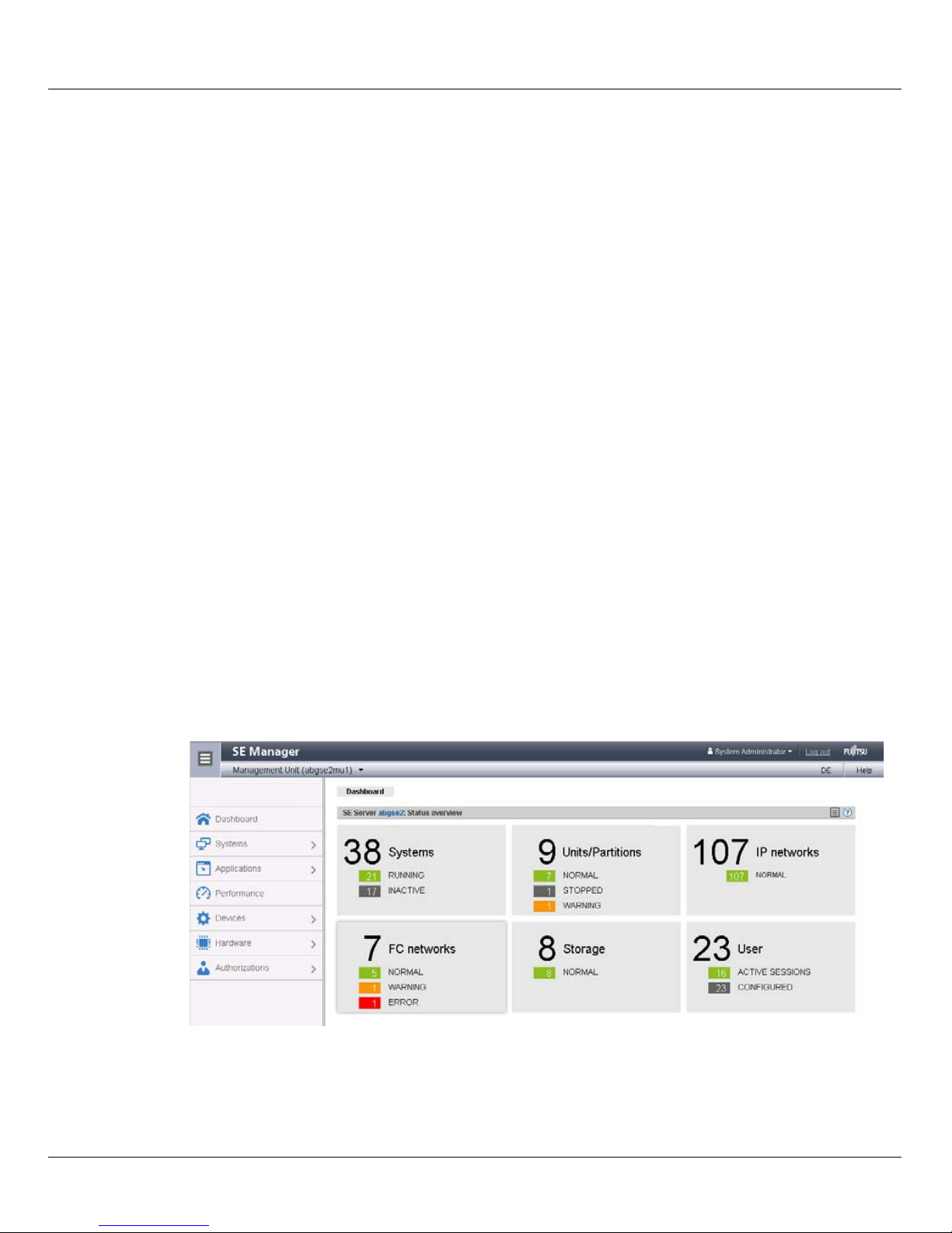
The Dashboard tab opens as the welcome page. It provides a quick overview of the
systems, units, IP networks, FC networks, storage, and users of the SE server. The
information displayed is described in the SE Manager help.
Information on the topic of "session management" is provided in the “Operation and
Administration” manual [5].
16 U41857-J-Z125-1-76
Page 17

Architecture of the SE servers and networks Operating the SE Manager
2.4.1.2 Logging out
Logging out explicitly
Ê In the header area of the SE Manager main window click Log out to terminate the
session. See section “Main window” on page 18.
The login window opens.
Logging out because of a session timeout
If you do not log out explicitly, the session terminates if there is no activity for 20 minutes,
i.e. if the SE Manager registers no action in this time.
I When you want to start an action in the SE Manager after a session has timed out,
first the login window window appears, and you must log in again. Only after you
have done this will the action be executed.
Each user can change this setting for himself/herself in the range from 5 through 60 minutes
or exclude it:
Ê Click in the login information in the header area. A list containing the menu item
Individual settings opens.
Ê Click Individual settings. The Change update cycle and session timeout dialog box opens in
which you can enable/disable the session timeout and set the timeout in the range from
5 to 60 minutes.
The individual setting is stored in the SE Manager on a user-specific basis. Information
on the topic of "individual settings" is provided in the “Operation and Administration”
manual [5].
2.4.2 Working with the SE Manager
The section below describes the most important terms of the SE Manager interface and
working with the SE Manager. Detailed information on operating the SE Manager is
provided in the “Operation and Administration” manual [5].
Various window types are used in the SE Manager:
● Login window: a window in which you log in using your account and password.
See section “Logging in” on page 16.
U41857-J-Z125-1-76 17
Page 18
Operating the SE Manager Architecture of the SE servers and networks
● Main window: a window which is always visible between logging in and logging out on
12
3
4
ab cdef
the SE Manager; it contains the navigation elements and the workarea in which
information is output and actions are initiated.
See section “Main window” on page 18.
● Terminal window: Window which is opened from the SE Manager and enables access
to the BS2000 console, BS2000 dialog, SVP console or the MU shell. A terminal
window remains opened irrespective of the SE Manager session.
See section “Terminal window” on page 21.
● Dialog/Wizard: a window which opens when an action starts and closes again after the
action has been completed. It is also used to output error messages concerning the
action being performed. A wizard is a utility which takes you through a task in a number
of steps (dialog boxes).
● Online help window: a window which opens when the online help is called.
See section “Calling the online help” on page 23.
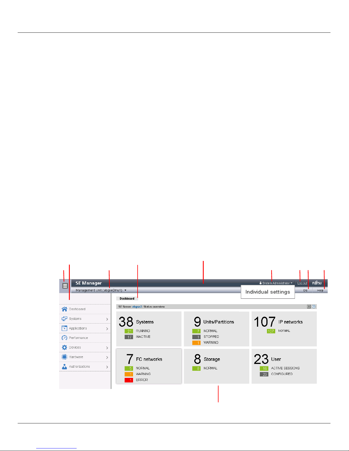
2.4.2.1 Main window
The main window of the SE Manager opens as soon as you have logged in on the SE
Manager. The next two figures provide an example to name the areas in the main window
and the principle controls.
SE Manager: areas in the main window
18 U41857-J-Z125-1-76
Page 19

Architecture of the SE servers and networks Operating the SE Manager
1: Tree structure
Main menus for selecting objects which are displayed in the working area
2: Tabs
Tabs for selecting objects which are displayed in the working area.
The update icon (rotating wheel) is displayed on the right-hand edge while the data
is being updated automatically.
3: Header area
Contains general information and settings for the SE Manager:
a Click the icon to hide or display the tree structure again.
b Management Unit (<unit name>) [location] provides information about the
Management Unit via which you are currently operating the SE Manager.
<unit name> is the name of the Management Unit.
If a location is configured with SYSLOCATION, <location> displays the
entry.
If the field ends with the arrow icon, redundant Management Units are
available. Click the field to obtain a list with links to the available
Management Units.
c Displays the login information: user account or, if defined, the person-
d Click Logout to end the session.
e Clicking the language option displayed (DE or EN) switches the web
f Click Help to open the SE Manager help in a new tab.
4: Working area
Displays data and enables dialog boxes and wizards to be opened to execute
actions.
related name of the user account.
Click the login information and Individual settings in the following pop-up. In
the subsequent dialog box you can set the cycle of the automatic update
and the session timeout for your user account.
A tool tip for login information displays the values currently set.
interface to the language selected.
U41857-J-Z125-1-76 19
Page 20

Operating the SE Manager Architecture of the SE servers and networks
SE Manager: elements of the main window
1
2
7
6
3
4
5a
5b
1 Active main menu of the tree structure
2 Active tab
3 Update icon to manually update the displayed information. This icon is displayed when the
automatic update is suspended. If the automatic update is active, the rotating wheel is
briefly displayed as an update icon in the rhythm of the update.
4 Help icon for calling the SE Manager help on a context-sensitive basis (see page 23)
5
a, b
The information is subdivided into groups (in the example above, 5a and 5b). Each group
contains one or more tables with properties of the objects displayed.
6 Icons for triggering actions
7 Number of entries in the table Total: <n> or Total <objects>: <n>
20 U41857-J-Z125-1-76
Page 21

Architecture of the SE servers and networks Operating the SE Manager
2.4.2.2 Terminal window
BS2000 console window, BS2000 dialog box, SVP console window, and shell terminal (CLI)
are opened in a separate terminal window after they are called in the SE Manager.
Subsequently the terminal window remains open irrespective of the SE Manager's session.
i Note that for further entries you may first need to click in the window to activate it.
The terminal window and its embedding in the SE Manager have the following properties,
among others:
● No further login is required when the terminal window is called.
● The size of the window can be changed flexibly.
● A virtual keyboard (matching the functionality):
The virtual keyboard enables all required characters and function keys to be entered
irrespective of the real keyboard's layout.
● Copy & paste functions:
– Copy/paste with the context menu in the terminal window
– Cross-window copy/paste (terminal window ↔ Windows) under Windows
→Windows:
Copying with COPY (context menu) or CTRL+C in the terminal window.
Pasting with Paste (context menu) or CTRL+V in Windows.
→Terminal window:
Copying with Copy (context menu) or CTRL+C in Windows.
Pasting with PA S T E (context menu) in the terminal window or via the menu bar of
Firefox (no CTRL+V is possible in the terminal window!)
● In the event of a loss of connection, the Connect button appears in the middle of the
terminal window. When you click this button, the terminal window session is continued
and you can once again make entries. A prerequisite for this is that the SE Manager
session in which the terminal window was opened is still active.
I If you want more than one terminal window to remain open in parallel (e.g. with
BS2000 console windows), this must also be supported on the client side by the
number of possible connections to a server. You must configure your browser
appropriately to permit this (see "SE Manager interface" in the “Operation and
Administration” manual [5]).
U41857-J-Z125-1-76 21
Page 22

Operating the SE Manager Architecture of the SE servers and networks
2.4.2.3 Calling an object or function in the SE Manager
Proceed as follows to call a function area in the SE Manager:
Ê Select an object or function in the primary navigation by clicking it.
A tab opens in the working area which enables you to manage or operate the object or
function Some functions are distributed over more than one tab, and these are
displayed at the top of the working area.
In the working area the content which belongs to the function area of the first tab is
displayed in one or more tables. Buttons or icons may also be available to execute
actions.
Ê If required, select another tab by clicking it.
Alternatively, you can also switch directly between the associated tabs in the tree
structure using an object's or function's tool tip.
The content of the working area changes if you select another tab.
The selected menu item and the selected tab are highlighted by being displayed in bold
black print against a blue or gray background.
Example
Hardware → Server → <unit name>(MU) → Service, Update tab
i The objects and functions which are displayed in the tree structure depend on the
server component and the configuration.
2.4.2.4 Navigation
The navigation in the SE Manager is distributed over the main menus Dashboard, Systems,
Application, Performance, Devices, Hardware, and Authorizations. With the exception of
Dashboard and Performance, all the main menus can be expanded.
When you click a main menu, the tree structure beneath it expands. Below this you see
objects and functions as links. Navigation using the main menus is also referred to as the
primary navigation.
When you click a link, a tab opens in the working area which enables you to manage or
operate the object or function Some functions are distributed over more than one tab, and
these are displayed at the top of the working area. These tabs are also referred to as
secondary navigation.
22 U41857-J-Z125-1-76
Page 23

Architecture of the SE servers and networks Operating the SE Manager
A main menu expands in the following cases:
● When you click the main menu again.
● When you click a link in another main menu.
2.4.2.5 Authorizations
The scope and thus the visibility of the functions depends on the role which is assigned to
your account.
New links are created in the tree structure for the following functions:
● Systems main menu:
– when creating a BS2000 VM
– when creating a XenVM
– when creating a virtual machine on an Application Unit
● IP networks main menu:
when creating a new network
In the tree structure an operator with configured individual rights sees only the BS2000 VMs
which are permitted for him/her. A XenVM administrator sees only the functions for
managing the XenVMs.
The BS2000 administrator and AU administrator roles are supported in M2000 V6.1 and
higher. A BS2000 administrator sees the functions which are needed to operate BS2000
systems in the tree structure and also has the BS2000-related administrator authorizations.
An AU administrator sees the functions which are needed to operate the systems on AUs
in the tree structure and also has the AU-related administrator authorizations.
Overviews of the role-specific tasks and functions are provided in the “Operation and
Administration” manual [5] and in the online help.
2.4.2.6 Calling the online help
The SE Manager incorporates an integrated, context-sensitive online help, the SE Manager
help. You can call the SE Manager help in two ways:
● Clicking Help in the header area of the SE Manager calls the SE Manager help's
welcome page in a new tab in the browser window.
● Clicking the Help icon (question mark) in a selected group displays the information on
the functionality of the group in a new tab in the browser window.
Information on working with the SE Manager help is provided in the “Operation and
Administration” manual [5].
U41857-J-Z125-1-76 23
Page 24

Operating the SE Manager Architecture of the SE servers and networks
24 U41857-J-Z125-1-76
Page 25

3 Power-on, starting up BS2000, shutdown
This chapter describes a simple way to power on the Management Unit, to power on other
units of the SE server with the SE Manager, and to start up the BS2000 operating system.
Descriptions of how to shut down BS2000 and to power off the units of the SE server are
also provided.
3.1 Powering on the Management Unit remotely
This section describes how you log in remotely on the iRMC (integrated Remote
Management Controller) of the Management Unit and power on the MU via its user
interface.
Ê Open a browser window on your administration PC.
Ê Enter the IP address of the iRMC of the MU.
I If the browser now displays a warning about the security certificate, click
Continue to this website.
The browser displays the iRMC’s graphical user interface with a note in the work area that
it is necessary to log in on the iRMC:
Ê Click Login.
U41857-J-Z125-1-76 25
Page 26
Powering on the Management Unit remotely Power-on, starting up BS2000, shutdown
The login window opens in the work area:
Ê Enter admin (or another administrator account) as the iRMC account.
Ê Enter the current password of the specified account.
i When the SE server is supplied, the default account admin is configured for the
administrator on the iRMC of the MU. admin is set as this account's password.
Change the password immediately after you have logged in for the first
time.
Ê Click OK.
After a successful login the browser window displays the System Overview menu item of
the iRMC’s graphical user interface. The System Status group shows that the MU is shut
down.
Ê In the navigation select Console Redirection → Video Redirection.
The Advanced Video Redirection tab is displayed.
26 U41857-J-Z125-1-76
Page 27
Power-on, starting up BS2000, shutdown Powering on the Management Unit remotely
Ê In the Video Redirection content area click Start Video Redirection (Java Web Start).
I If the browser now displays a warning about the security certificate, click
Continue to this website.
A window opens to display the console. As the MU has not yet been powered on, the
console window is empty.
Ê Switch to the iRMC window.
Ê In the navigation select Power Management → Power ON/OFF.
Ê In the Power Control content area enable the Power On option.
Ê Click Apply.
Ê Answer the question Do you really want the server to ’Power On’? by clicking Confirm.
The MU powers itself on and starts up. Some minutes will pass before it is possible to log
in on the SE Manager. You can see in the console window when it is possible:
Ê Switch to the console window.
The current progress of the startup operation is displayed here.
The appearance of a login request indicates that the system has started up.
Ê Close the console and log out from the iRMC Web GUI.
You can now log in on the SE Manager in order to power on the Server Units and other units
(see Abschnitt „Powering on Server Units and other units“ auf Seite 29).
U41857-J-Z125-1-76 27
Page 28

Powering on the Management Unit via the local console Power-on, starting up BS2000, shutdown
3.2 Powering on the Management Unit via the local console
This section describes how you power on the Management Unit at the local console. You
are on the server rack of the SE server.
Ê Open the server rack.
Ê Pull out the draw with the local console and flap up the screen.
Ê Press the Power On key on the MU.
I By default the local console is attached to the MU. If the connection is attached to
the Server Unit, switch over to the MU using the console switch menu (press the
HOT KEY to call it).
The MU powers itself on and starts up. The startup messages are output on the local
console.
As soon as the system is ready, you receive the login request.
Ê Enter admin (or another administrator account) as the account.
Ê Enter admin as the password.
admin is the password of the admin account when the system is supplied. If it has
already been changed (or you are using a different password), you must enter the
current password (see also Abschnitt „Logging in“ auf Seite 16).
Ê Click Log in.
After a successful login a Gnome Desktop is loaded.
Ê Click Computer in the task bar (bottom left).
The Applications menu drops down.
Ê Double-click the Firefox icon to open the browser.
Ê Enter the IP address of the MU in the browser address bar (or alternatively localhost) to
call the SE Manager of the MU.
You can now log in on the SE Manager in order to power on the Server Units and other units
(see Abschnitt „Powering on Server Units and other units“ auf Seite 29).
28 U41857-J-Z125-1-76
Page 29
Power-on, starting up BS2000, shutdown Powering on Server Units and other units
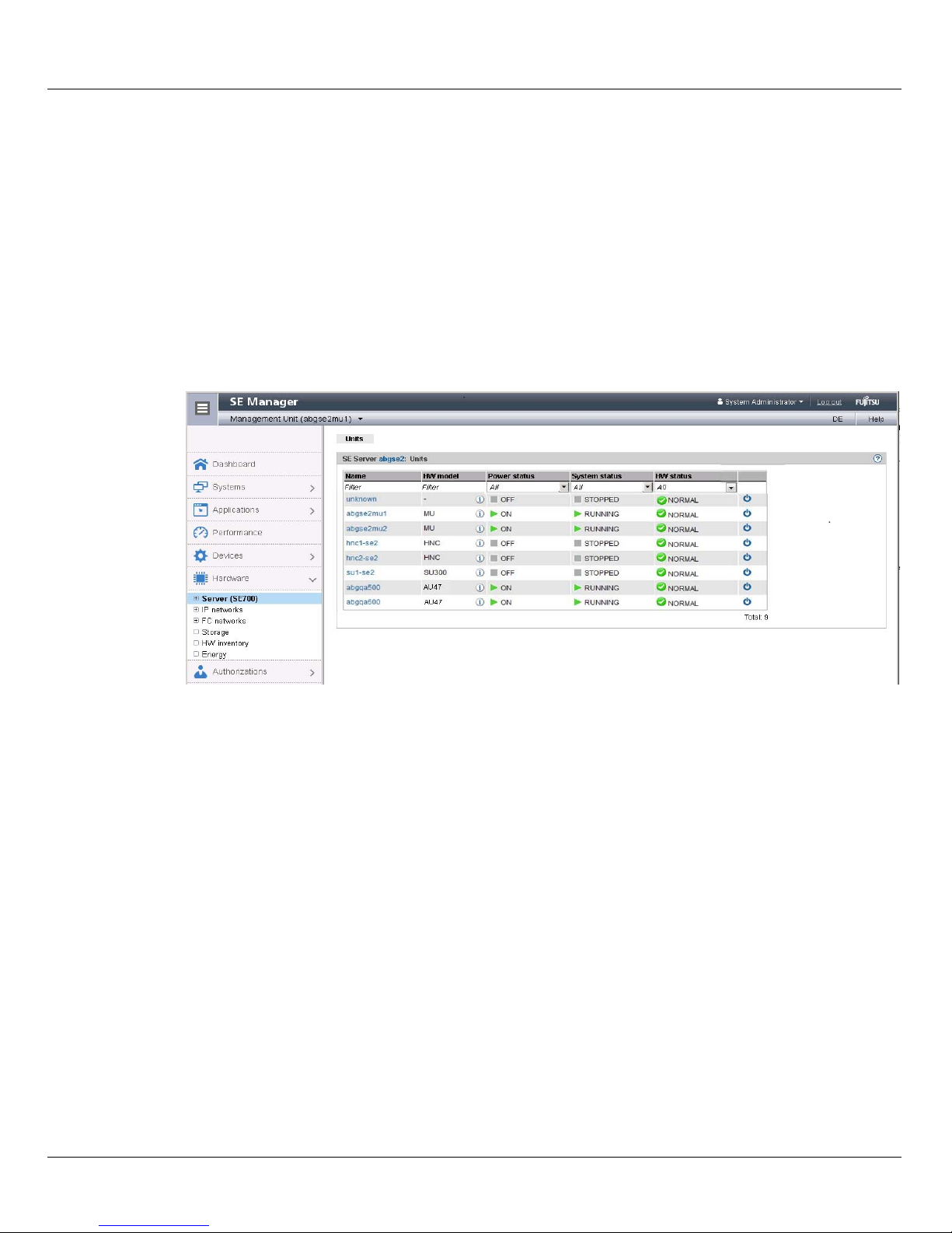
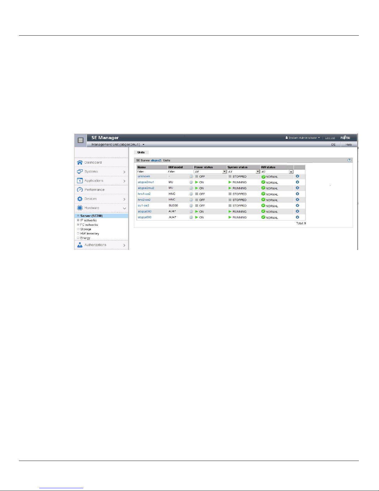
3.3 Powering on Server Units and other units
Call the SE Manager and log in, see Abschnitt „Calling the SE Manager“ auf Seite 15.
You manage the units of the SE server using the menu Hardware → Server (SE<model>).
When you expand this menu, all the existing units are listed.
Ê Select Hardware and click Server (SE<model>).
The example shows an SE700.
The Units tab displays information on Server Units, Management Units (also redundant
MUs), HNCs (only for models with SU /390) and Application Units of the SE server.
Depending on the status, you use the Units tab to power the required units on or off or
reboot them.
Switching the Server Unit on
Requirement
The unit is powered off (power status OFF).
Procedure
Ê Click the Power on icon by the required Server Unit and confirm the action with Execute
in the subsequent dialog box.
The powered-off unit is powered on. As soon as the Power status of the unit displays the
value On, you can start up BS2000 in accordance with the hardware.
i After a Server Unit has been powered on, depending on the operating mode set the
Native BS2000 system or the VMs are started up if an automatic startup (auto IPL)
has been configured for this purpose, see the “Operation and Administration”
manual [5].
U41857-J-Z125-1-76 29
Page 30

Starting up BS2000 (SU /390) Power-on, starting up BS2000, shutdown
Powering on further units
For BS2000 operation on an SU /390m the following units should also be powered on:
● In the case of MU redundancy the second MU should also be powered on. Only in this
way will it remain possible to continue operating the SVP of the SU /390 if the first MU
crashes. The SE Manager on the second MU will also remain available.
● To enable the BS2000 systems to communicate over the IP network and ensure access
to Net-Storage is possible, the HNC must be powered on. Redundant existing HNCs
should also be powered on.
3.4 Starting up BS2000 (SU /390)
A Server Unit /390 is operated via the SVP (Service Processor) after it has been powered
on.
SVP functions are operated under menu guidance on the SVP console using SVP frames.
i Some important SVP functions, for instance for IPL or IORSF, are also available
directly on the SE Manager or can alternatively be called in the KVP menu of the
BS2000 console, see the "Operation and Administration" manual [5].
The SVP console is accessed via the SE Manager:
Ê Select Systems → <unit>(SU</390>), BS2000 operation mode tab.
Ê In the SVP console group click Open.
i If the browser now displays a warning about the security certificate, click
Continue to this website.
30 U41857-J-Z125-1-76
Page 31
Power-on, starting up BS2000, shutdown Starting up BS2000 (SU /390)
The SVP console window opens.
Ê Press the Enter key. The MODE SELECTION FRAME appears.
i If the SVP has already been worked with, the last frame used will appear. You
reach the MODE SELECTION FRAME by entering
FR ML in the entry line.
U41857-J-Z125-1-76 31
Page 32

Starting up BS2000 (SU /390) Power-on, starting up BS2000, shutdown
You can operate the SVP console in the familiar manner using the keyboard. A virtual
keyboard is also available to you for making entries on the SVP console.
(Click the keyboard icon at the top right to open the virtual keyboard. Clicking the icon
again closes the keyboard.)
Enter the alphanumeric characters shown in the frame in the input fields marked by an
arrow (=>).
A detailed description of how to operate the SVP is provided in the "Server Unit /390"
Operating Manual [2].
32 U41857-J-Z125-1-76
Page 33

Power-on, starting up BS2000, shutdown Starting up BS2000 (SU /390)
Ê To load BS2000, enter FUNCTION ==> ld and press the Enter key. The PROGRAM
LOAD FRAME: DETAIL-1 frame will appear.
You can start execution of IPL with the entries in this frame.
The frame shows, among other things, the (current and preset) load device (also called
IPL or boot load device) of BS2000. As the Server Unit was rebooted, the IPL load
device from the auto IPL configuration is set. This can differ from the IPL load device of
the last IPL. If necessary, select a different load device under
IPL-DEVICE.
I Initial startup from the IPL load device requires a DIALOG startup. LOAD
FUNCTION ==> 3
Take note of the setting for
set. In VM2000 mode,
In Native BS2000 mode, a blank must be entered there.
Ê In VM2000 mode, switch to the PROGRAM LOAD FRAME: DETAIL-2 if necessary
using [PF9] in order to check the settings for loading the VM2000 firmware.
In VM2000 mode,
Ê For
LOAD FUNCTION ==> select one of the functions LOAD or START and press the Enter
key.
must be selected for this purpose.
PARMS ==>. This depends on the BS2000 operating mode
PARMS ==> 1 must be set.
VM MODE ==> 2 must be set there.
U41857-J-Z125-1-76 33
Page 34

Starting up BS2000 (SU /390) Power-on, starting up BS2000, shutdown
Ê Please monitor the further procedure on the BS2000 console. Take note of the console
messages and answer the question messages.
As a large number of messages are output one after the other, question messages can
also quickly “disappear”. The /SHOW-PENDING-MSG (or /STATUS MSG) command
enables you to have all the open question messages displayed again.
As soon as the message NSI0000 displays “System ready”, startup of BS2000 has already
been largely completed. You can continue to observe the current BS2000 session on the
console and, when necessary, react to system messages (e.g. reply to a mount message).
For information on console messages which are issued by M2000/X2000, see Abschnitt
„Messages on the BS2000 console“ auf Seite 42.
For more extensive administration tasks in BS2000, you must log in on BS2000, see
Abschnitt „Opening and terminating BS2000 dialog“ auf Seite 38.
Information on working with the SE Manager in Native BS2000 and VM2000 modes is
provided in the "Operation and Administration" manual [5].
34 U41857-J-Z125-1-76
Page 35

Power-on, starting up BS2000, shutdown Starting up BS2000 (SU x86)
3.5 Starting up BS2000 (SU x86)
BS2000 is started up on a Server Unit x86 in the KVP menu of the BS2000 console.
i Some important SVP functions, for instance for IPL, are also available directly on
the SE Manager, see the "Operation and Administration" manual [5].
Ê Depending on the SU x86's operating mode, select the following on the SE Manager:
● In BS2000 Native mode: Systems→ <unit>(SU<x86>) → BS2000 → MONITOR,
Operation tab
● In VM2000 mode: Systems→ <unit>(SU<x86>) → Virtual machines → BS2000 →
MONITOR, Operation tab
Alternatively, select Systems→ <unit>(SU<x86>), Overview tab When you click on the
name of the BS2000 system, the SE Manager switches to the Operation tab of the
BS2000 system.
Ê In the Console and dialog group, click Open on the BS2000 console function.
i The console mnemonic must be configured in the BS2000/OSD/BC parameter file;
in the default case, the console mnemonics C0 and C1 are defined.
If the browser now displays a warning about the security certificate, click Continue
to this website.
A BS2000 console window opens. The console is loaded. As BS2000 is not yet active, no
console messages can yet be seen.
Ê Press the function key [F2] on your keyboard.
Alternative:
Click the function key [F2] on the virtual keyboard. (Click the keyboard icon at the
top right to open the virtual keyboard. Clicking the icon again closes the keyboard.)
The KVP menu below is then displayed.
U41857-J-Z125-1-76 35
Page 36

Starting up BS2000 (SU x86) Power-on, starting up BS2000, shutdown
Main KVP Function Menu
==========================================================================
0 - Exit
1 - Permit input (on)
2 - Inhibit input (off)
3 - Change password
4 - View last messages
5 - Show logging files
6 - SVP commands
7 - Programmable function keys
8 - Help
==========================================================================
Please enter value:
Ê Click next to Please enter value: and enter 6.
The menu with the SVP commands is then displayed:
SVP commands
==========================================================================
0 - Back to main menu
1 - Start BS2000
2 - Start BS2000 dump IPL
3 - Dump IOH memory
4 - Report actual default parameters for IPL
==========================================================================
Please enter value:
Ê Enter 1.
The menu containing the IPL functions for starting BS2000 is then displayed:
Start BS2000
==========================================================================
0 - Back to main menu
1 - Execute with current parameters
2 - Execute with preset parameters
3 - Execute with current parameters and save into preset parameters
Change params: current preset parameters
a - IPL load device: 9908 9908
b - Consol device: Z0 Z0
c - Startup mode [a|d|f]: a f
d - BS2000 systemname: ABGAFR01 ABGAFR01
e - Clear BS2000 memory [y|n]: n n
==========================================================================
Please enter value:
36 U41857-J-Z125-1-76
Page 37

Power-on, starting up BS2000, shutdown Starting up BS2000 (SU x86)
The menu shows, among other things, the (current and preset) load device (also called
IPL or boot load device) of BS2000. As the Server Unit was rebooted, the IPL load
device from the auto IPL configuration is set. This can differ from the IPL load device of
the last IPL. If necessary, use menu item a to select a different IPL load device.
I Initial startup from the IPL load device requires a DIALOG startup. For this
purpose the value d must be set for the IPL parameter Startup mode. If
necessary, select this value using menu item c.
Ê Enter 1.
The settings are saved and IPL starts. The KVP is closed and the current console
messages are displayed.
Ê Take note of the console messages and answer the question messages.
As a large number of messages are output one after the other, question messages can
also quickly “disappear”. The /SHOW-PENDING-MSG (or /STATUS MSG) command
enables you to have all the open question messages displayed again.
As soon as the message NSI0000 displays “System ready”, startup of BS2000 has already
been largely completed. You can continue to observe the current BS2000 session on the
console and, when necessary, react to system messages (e.g. reply to a mount message).
For information on console messages which are issued by M2000/X2000, see Abschnitt
„Messages on the BS2000 console“ auf Seite 42.
The [F3] and [F4] keys enable you to scroll backward and forward in the history of the
console inputs. Pressing [Ctrl] + [d] or entering ::c terminates the console.
For more extensive administration tasks in BS2000, you must log in on BS2000, see
Abschnitt „Opening and terminating BS2000 dialog“ auf Seite 38.
Information on working with the SE Manager in Native BS2000 and VM2000 modes is
provided in the "Operation and Administration" manual [5].
U41857-J-Z125-1-76 37
Page 38

Opening and terminating BS2000 dialog Power-on, starting up BS2000, shutdown
3.6 Opening and terminating BS2000 dialog
You perform administration tasks in the BS2000 system in a dialog task. To start a dialog
task you require a dialog window in which you can log into the BS2000 system. You can log
in on the BS2000 system as soon as BS2000’s data communication system has started.
Ê Iconize the opened console window and switch once more to the main window of the
SE Manager.
That is where the Operation tab of the BS2000 system which was previously started was
most recently opened (take note of „Logging out because of a session timeout“ auf
Seite 17).
Ê In the Console and dialog group, click Open in the BS2000 dialog function.
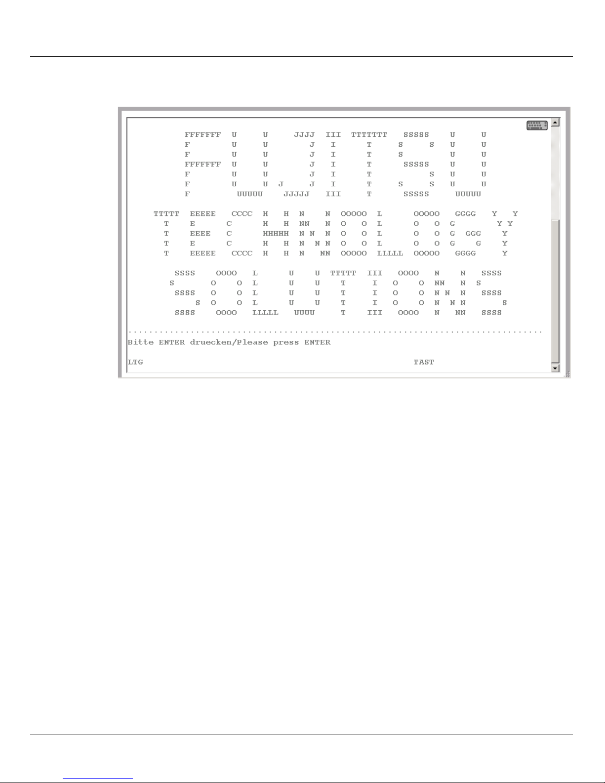
A BS2000 dialog window opens.
...........................................
CN04 CONNECTED WITH MANLO1$DIALOG;IND=C'::'
% JMS0150 INSTALLATION '390SU- 700-20', BS2000 VERSION 'V190', HOST
'D020ZE01': PLEASE ENTER '/SET-LOGON-PARAMETERS' OR '?'
/set-logon-parameters ....
LTG TAST
After you have logged in successfully using the /SET-LOGON-PARAMETERS command,
you can enter commands and perform your tasks in BS2000.
I To complete an entry, click the [DUE1] key in the key panel of the virtual keyboard
or press the Enter key on your keyboard.
38 U41857-J-Z125-1-76
Page 39

Power-on, starting up BS2000, shutdown Opening and terminating BS2000 dialog
Terminating a BS2000 dialog and closing the dialog window
Proceed as follows to close the dialog window:
Ê Terminate your dialog task using the /EXIT-JOB command (or /LOGOFF).
BS2000 terminates your task and the connection to BS2000 is cleared.
Ê Respond to the request PLEASE ACKNOWLEDGE by pressing the Enter key.
Ê The main window of the terminal emulation opens.
Ê Enter e and press the Enter key to terminate terminal emulation.
The window is closed.
U41857-J-Z125-1-76 39
Page 40

Shutting down BS2000 via the BS2000 console Power-on, starting up BS2000, shutdown
3.7 Shutting down BS2000 via the BS2000 console
This section describes how you shut down BS20000.
Ê In the SE Manager, select Systems, Overview tab.
The system overview lists all the systems which exist on the SE server. BS2000
systems are either of the type Native BS2000 or of the type VM2000.
Ê Select the BS2000 system to be shut down and click on the name.
In the tree structure the SE Manager switches to the BS2000 system concerned and
displays the Operation tab.
Ê In the Console and dialog, group, click Open in the BS2000 console function.
A BS2000 console window opens. The console is loaded.
Ê Enter the /SHUTDOWN command (if necessary with specifications for the MODE and
MESSAGE operands to warn the participants in the BS2000 dialog).
Ê Take note of the console messages and answer any question messages which are
issued.
Output of the message EXC0557 SHUTDOWN PROCESSING COMPLETED indicates that
shutdown of BS2000 has been completed.
Ê Close the console window.
i When you shut down the monitor system of a Server Unit operated in VM2000
mode, VM2000 mode is also terminated, i.e. all BS2000 VMs are shut down.
Provision should therefore be made beforehand in the monitor system to ensure
that VM2000 operation is terminated correctly so that all guest systems can be shut
down properly.
For information on console messages which are issued by M2000/X2000, see Abschnitt
„Messages on the BS2000 console“ auf Seite 42.
40 U41857-J-Z125-1-76
Page 41
Power-on, starting up BS2000, shutdown Powering off Server Units and other units
3.8 Powering off Server Units and other units
You manage the units of the SE server using the menu Hardware → Server (SE<model>).
When you expand this menu, all the existing units are listed.
Ê Select Hardware and click Server (SE<model>).
The Units tab displays information on Server Units, Management Units (also redundant
MUs), HNCs (SU /390), and Application Units of the SE server.
Depending on the status, you use the Units tab to power a unit on or off or reboot it.
Shutting down the unit or immediately powering it off
Requirement
You can power off a unit only when the unit is accessible, i.e. the HW status is not
NOT_ACCESSIBLE.
Procedure
Ê Click the Power off icon by the required unit.
Ê In the dialog box which then appears, select the option Shut down or Power off
immediately and confirm the action with Execute.
i Only Power off immediately is available for the SU /390. In this case shutdown is
possible only via the BS2000 console (see Abschnitt „Shutting down BS2000
via the BS2000 console“ auf Seite 40).
The unit is shut down or powered off immediately. You will receive a message when the
operation has been completed.
U41857-J-Z125-1-76 41
Page 42
Messages on the BS2000 console Power-on, starting up BS2000, shutdown
3.9 Messages on the BS2000 console
The base system M2000 or X2000 issues messages on the BS2000 console. On an SU
/390 these messages are issued by the M2000 of the MU, and on an SU x86 by the X2000
of the SU. With the exception of the messages for write operations to CDROM/DVD, these
messages are not issued via the BS2000 system component MIP (Message Improvement
Processing) and are therefore not stored in a BS2000 message file.
Specifically, M2000/X2000 issues messages of the following message classes on the
BS2000 console:
Message
class
KVP Messages of the console distribution program (KVP)
SVR Messages of the SVP emulation (to SU x86 only)
IOD Messages of the I/O handler for bus devices (to SU x86 only)
HAL Messages of the Hardware Abstraction Layer (to SU x86 only)
SNX Messages for write operations to CDROM/DVD CDROM/DVD (SNXCDxx) or
In BS2000 OSD/BC V10.0 and higher, you can inquire response and any meaning texts for
messages of M2000/X2000 using the HTML application "System messages" (online at
http://manuals.ts.fujitsu.com or on the "BS2000 SoftBooks" DVD).
Meaning
messages relating to a fault in a peripheral component which cannot be reported via
an I/O to BS2000.
i In BS2000 you can only inquire the message text, meaning and response text for a
message code with the HELP-MSG-INFORMATION command only if the message
is stored in a BS2000 message file.
42 U41857-J-Z125-1-76
Page 43

4 Setting the system time or configuring the NTP
The Management Units are available as NTP servers for all units of the server via the
internal LAN. SU x86 and HNC are preconfigured with respect to NTP; AU configuration
must be performed as required by the administrator responsible.
To ensure high time accuracy, you can also configure automatic time leveling with a socalled NTP server, e.g. one which supplies a time which is as accurate as a radio clock,
using NTP (Network Time Protocol).
Effect on the time setting of the systems on the SE server
The time settings of the other systems are synchronized with the system time of the
Management Unit. The Management Unit is the basic timer.
When changes are made to the time management which affect the Server Unit, bear in
mind that the time settings in BS2000 systems and of XenVMs that are started later are also
affected. Here you should in particular avoid large leaps in time which are caused by setting
the time manually.
Details on BS2000 are provided in the "Synchronization of the system time" section in the
"BS2000 OSD/BC System Administration" manual.
U41857-J-Z125-1-76 43
Page 44

Setting the system time or configuring the NTP
Ê Select Hardware → Server (SE<model>) → <unit>(MU) → Management, System time tab:
The System time tab displays the NTP servers which are entered for automatic time
synchronization and the local time of the MU.
Adding or removing an NTP server
Ê To add an NTP server, click Add NTP server in the Time synchronization with NTP server
group, and after making the necessary entries confirm the action.
Ê To remove an NTP server from the NTP configuration, click the Remove icon by the
required NTP server in the Time synchronization with NTP server group and confirm the
action.
i In the case of an SE server with redundant MU, the MU with the index 1 should by
default be entered as an NTP server on the MU with the index2 (for details see the
“Operation and Administration” manual [5].
Changing the local time
You can only change the local time if no NTP server is active.
i Changes to the time can also have an effect on productive operation. See also
section „Effect on the time setting of the systems on the SE server“ auf Seite 43".
Ê In the Local time group click the Change icon, and after making the necessary entries
confirm the action.
44 U41857-J-Z125-1-76
Page 45

5 Application Units
As a rule an operating system of another vendor (Windows, Linux or Unix systems) runs on
an Application Unit. The scope of the setting and display options thus depends on the
operating system concerned. On an AU, an operating system can also be used in Native
mode on the AU, on a guest system which was configured under HyperV Windows Server
on the AU, or on a VM which was configured under VMware vSphere on the AU.
Application Units are displayed in the tree structure as <unit name>(AU<model>).
i In M2000 V6.1 and higher, AUs are also supported on the basis of
PRIMEQUEST. When the AU is supported as an appliance delivery on the basis
of Oracle VM Server from FUJITSU, it is displayed as a Database Unit with the
short name DBU87. Otherwise the short name is displayed.
In the case of an AU87 or DBU87, systems run on the individual partitions of the
AU. You operate a partition via the Management Board. In the Operation tab,
you open the web interface of the Management Board (instead of the iRMC) in
the Operation group for this purpose.
5.1 Powering the Application Unit on and off via the iRMC
You operate a Native system via the Operation tab.
Ê In the tree structure select Systems → <unit name>(AU<model>), Operation tab.
Ê Click iRMC and Open in the Operation tab in the Operation group.
The web interface of the AU's iRMC opens.
Ê Click Login.
The login window is opened in the work area.
Ê Enter the user name and password.
Ê Click OK.
After a successful login the browser window displays the System Overview menu item of
the iRMC’s graphical user interface. The System Status group shows that the AU is
powered off.
U41857-J-Z125-1-76 45
Page 46
Powering the Application Unit on and off via the iRMC Application Units
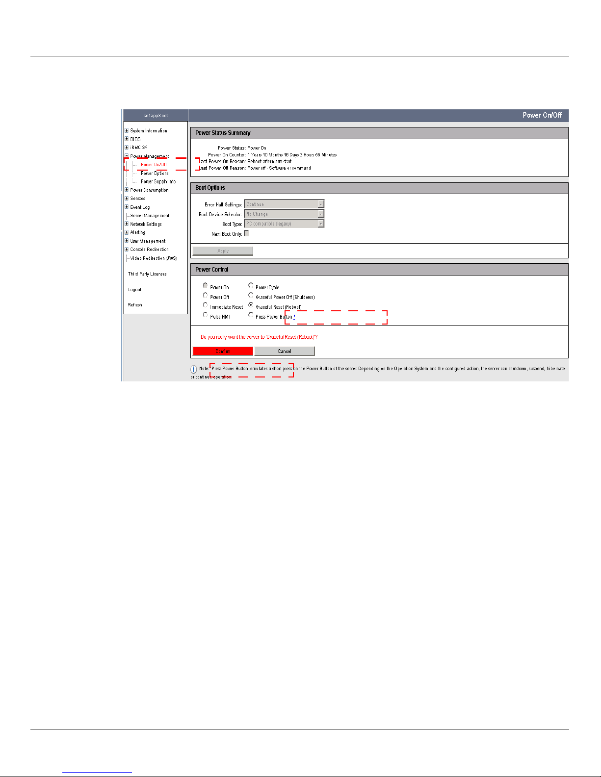
Ê In the navigation select Power Management → Power ON/OFF.
Ê In the Power Control group activate the option you require (Graceful Reset (Reboot) is
selected in the example).
Ê Click Apply.
Ê Reply to the subsequent question by clicking Confirm.
You can observe the status of the AU in the overview of the units:
Ê Select Hardware → Server (SE<model>, Units tab.
Alternatively, depending on the status of the AU you can start up or shut down the AU's
Native system in the SE Manager:
Ê In the Units icon, click the Power on/Power off icon, and if you want to shut down the AU
select the Shutdown action.
You can also execute the action which is currently permissible under Systems → <unit
name>(AU<model>) in the Action group of the Operation tab.
46 U41857-J-Z125-1-76
Page 47

Application Units Embedding an application or link in the SE Manager
i In M2000 V6.1 and higher, AUs are also supported on the basis of
PRIMEQUEST. AU87 or DBU87 is displayed as the short name.
In the case of an AU87 or DBU87, you operate the individual partitions of the
AU via a Management Board. In the Operation tab, you open the web interface
of the Management Board (instead of the iRMC) in the Operation group for this
purpose.
For an AU87 or DBU87, the various partitions are powered on/off (not the entire
Unit).
5.2 Embedding an application or link in the SE Manager
With M2000 V6.0 you can embed independent links to any internet site in the SE Manager.
This enables you to switch directly to a web application or internet site from the SE
Manager. Each link opens in a separate tab or window of the browser. In M2000 V6.0, such
links are still called "user-defined management applications."
In M2000 V6.1 and higher, the functionality for connecting applications extends to AUs. The
independent links are then called "user-defined links" and are managed in the User-defined
links group. An application which can be integrated into the SE Manager infrastructure, such
as the OVM Manager, is then called a "user-defined management application" and is
managed in the User-defined management applications group. Each application opens in a
separate tab or window in the browser.
Ê Select Applications → User-defined management applications, Administration tab.
The Administration tab displays the list of the user-defined management applications
and the list of the user-defined links which are embedded in in the SE Manager.
Ê The Change and Remove icons enable you to change the properties of user-defined
applications or links or to remove the link from the SE Manager.
Ê Click Link user-defined management applications to embed another application in the SE
Manager.
Ê Click Embed user-defined link to embed another link in an internet site in the SE Manager.
U41857-J-Z125-1-76 47
Page 48

Embedding an application or link in the SE Manager Application Units
48 U41857-J-Z125-1-76
Page 49

Related publications
You will find the manuals on the internet at http://manuals.ts.fujitsu.com. You can order printed
versions of manuals which are displayed with the order number.
In addition to this Quick Guide, the documentation for the SE servers consists of the
SE700 / SE500 / SE300 Operating Manual (comprising several modules) and the User
Guides “Operation and Administration” and “Security Manual”.
[1] FUJITSU Server BS2000
SE700 / SE500 / SE300
Basic Operating Manual
[2] FUJITSU Server BS2000
SE700 / SE500
Server Unit /390
Operating Manual
[3] FUJITSU Server BS2000
SE700 / SE500 / SE300
Server Unit x86
Operating Manual
[4] FUJITSU Server BS2000
SE700 / SE500 / SE300
Additive Components
Operating Manual
[5] FUJITSU Server BS2000
SE700 / SE500 / SE300
Operation and Administration
User Guide
[6] FUJITSU Server BS2000
SE700 / SE500 / SE300
Security Manual
U41857-J-Z125-1-76 49
Page 50

Related publications
[7] FUJITSU Server BS2000
SE700 / SE500 / SE300
Quick Guide
A additional documentation is available for the SE servers. As the BS2000 OSD/XC
software package comprises the BS2000 OSD/BC operating system and additional
system-related software products, the documentation for BS2000 OSD/XC consists of the
following:
● The manuals on BS2000 OSD/BC, which provide the basic literature on BS2000 OSD/
XC.
● The manuals for the system-related software products which belong to the BS2000
OSD/XC software package also apply.
Any additions to the manuals are described in the Readme files for the various product
versions. These Readme files are available at http://manuals.ts.fujitsu.com under the various
products.
Current information, version and hardware dependencies and instructions for installing and
using a product version are contained in the associated Release Notice. Release Notices,
in particular those relating to BS2000 OSD/XC, M2000, X2000, and HNC, are available at
http://manuals.ts.fujitsu.com.
50 U41857-J-Z125-1-76
Page 51

Index
A
abbreviations 10
account 16
ACL (Access Control List) 14
Application Unit 11
AU (Application Unit) 10
AU87 47
B
boot load device 33, 37
BS2000 console, messages 42
BS2000 server 10
D
Dashboard 16
data network
private 13
public 13
Data Network Private (DANPR) 13
Data Network Public (DANPU) 13
DBU (Data Base Unit) 45
DBU87 47
H
HAL (message class) 42
HNC (High Speed Network Connect) 10
L
load device 33, 37
logging in on the SE Manager 16
login window 15
M
main window 18
Management Administration Network Public
(MANPU) 13
Management Board 45
Management Control Network Local
(MCNLO) 13
Management Control Network Private
(MCNPR) 13
management network
private 13
Public 13
Management Optional Network Private
(MONPR) 13
Management Optional Network Public
(MONPU) 13
Management SVP Network Private (MSNPR) 13
Management Unit 11
messages of M2000/X2000 42
metalanguage 9
MU (Management Unit) 10
I
initial password 16, 26
IOD (message class) 42
IPL load device 33, 37
iRMC 25, 45
K
KVP (message class) 42
U41857-J-Z125-1-76 51
N
names 10
Net Unit 11 , 12
notational conventions 9
NTP (Network Time Protocol) 43
NTP server 43
Page 52

Index
O
online help 23
T
time setting 43
P
password 16
powering off, unit 41
powering on, unit 29
R
Readme file 8
S
S server 10
SE Manager 12
authorizations 23
calling function 22
calling object 22
interface 17
logging in 16
navigation 22
online help 23
welcome page 16
SE server 11
SE300 10
SE500 10
SE700 10
Server Unit 11
SNX (message class) 42
SQ server 10
standard account, password 16, 26
SU (Server Unit) 10
SU /390 10
SU x86 10
SVP commands 36
SVR (message class) 42
U
unit
powering off 41
powering on 29
user-defined link 47
user-defined management application 47
W
welcome page SE Manager 16
window type 17
52 U41857-J-Z125-1-76
 Loading...