

Page 1

T101-2293-1,03,02
GX4000 R3.0 Series
E band Impulse Radio System
User Guide
T101-2293-01
Issue 1.03.02
2014 July
FUJITSU LIMITED
Page 2

01 Issue History
Issue Number
Issue Date
History
1.02.01
9th December, 2013
First issue
1.02.02
30th May, 2014
Second issue 1
Additional figure (Mounting kit)
1.03.01
23th July, 2014
Third issue 1
Reviewed all and revised
Additional figure (Antenna & Scope mounting kit)
1.03.02
23th July, 2014
Third issue 2
Additional table (throughput[RFC2544] ) etc.
02 Scope
This document describes all of the Operation Manual for Fujitsu’s BroadOne GX4000 series
E band Impulse Radio System. Please note that the specifications are subjected to change
without notice due to Fujitsu’s further design improvements.
03 Non-Disclosure
Fujitsu Limited has taken every care that the contents of this document are correct at the time
of going to press. If any errors are found, or any other comments are wished to be made,
Please do not hesitate to contact us.
The contents of this document are protected under copyright and contain commercially and/or
technically confidential information. The content of the document must not be used other than
for purpose for which it was not provided nor may it be disclosed or copied (by authorized
recipient or otherwise) without the prior written consent of an authorized officer of Fujitsu
Limited.
Page 3

04 Contents
1. System Description
1.1 Overview ………………………………………………………… 1-1
1.2 System Overview ………………………………………………. 1-1
1.3 Ordering Information …………………………………………… 1-4
1.4 General Specification ………………………………………….. 1-14
1.5 Environmental Specification ………………………………….. 1-24
1.6 Power requirement …………………………………………….. 1-29
1.7 Reference Data(Throughput) ………………………………….. 1-34
2. Installation & Site Survey
2.1 Overview ………………………………………………………… 2-1
2.2 Installation & Site Survey Guideline ………………………….. 2-1
2.3 Unpacking ……………………………………………………….. 2-3
2.4 Antenna Pole Mounting …………………………………………. 2-4
2.4.1 Antenna Pole Mounting Overview……………………………….2-4
2.4.2 Goods Necessary for Installation……………………………….. 2-5
2.4.3 Mechanical Dimension of Goods……………………………….. 2-6
2.4.4 Breakdown Components of Mounting Kit………………………. 2-8
2.4.5 Fixing Mounting Kit to Pole………………………………………. 2-9
2.5 Assembly of Connection Material with E-Band IR .…………… 2-15
2.6 Confirmation of Antenna Polarization…….……………………. 2-16
2.7 Assembly of Antenna Base and E-Band IR…….…………….. 2-17
2.8 Cable & Connector ……………………………………………….. 2-18
2.8.1 Cable and Connector Code necessary for Installation……….. 2-18
2.8.2 Cable and Connector Description………………………………. 2-18
2.8.3 Cable and Connector Used …………………………………..… 2-19
2.8.4 Pin Assignment of Connector ………………………………….. 2-21
2.8.5 Cable Connector Location ………………………………………. 2-23
2.8.6 Cable Connection with External Equipment ………………..… 2-23
2.9 Cable Connection between External Equipment …………..… 2-24
2.10 Assembly of Connector …………………………………………. 2-27
2.10.1 Optical Connector …………………………………………………2-27
2.10.2 Ether Connector ………………………………………………….. 2-27.
2.10.3 I/O Connector ………………………………………………………2-27
2.10.4 Power Supply Cable ……………………………………………….2-32
3. Commissioning Test
3.1 Overview …………………………………………………………. 3-1
3.2 Preparation ………………………………………………………. 3-1
3.3 Power Supply ON ……………………………………………….. 3-2
3.4 Starting WebLT ………………………………………………….. 3-2
3.5 Antenna Alignment Guideline ………………………………….. 3-3
3.6 Antenna Alignment Procedure …………………………………. 3-6
3.7 Continuity Test ……………………………………………………. 3-11
3.8 Applicable/Not Applicable of Menu Tree ……………………… 3-15
4. Maintenance & Trouble Shooting
4.1 Overview …………………………………………………………. 4-1
4.2 Routine Maintenance …………………………………………… 4-1
4.3 Loopback Function ……………………………………………… 4-5
4.4 ODU Removal for Replacement ……………………………….. 4-7
4.5 ODU Replacement ………………………………………………. 4-9
4.6 Firmware Update ………………………………………………… 4-12
4.7 Housekeeping ……………………………………………………. 4-13
Page 4

5. Web-Based Local Terminal (WebLT)
5.1 WebLT …………………………………………………………….. 5-1
5.2 Getting Started with WebLT ……………………………………. 5-2
5.3 Menu Tree for Ethernet Interface ………………………………. 5-8
5.4 Menu Tree for CPRI Interface ………………………………….. 5-10
5.5 WebLT Menu and Description …………………………………. 5-13
Summary ………………………………………………………….. 5-15
Configuration > Alarm …………………………………………….5-17
Configuration > Radio …………………………………………….5-18
Configuration > System > Information ……………………… 5-19
Configuration > System > IP ………………………………….. 5-20
Configuration > System > NTP ……………………………….. 5-21
Configuration > System > Log Server ……………………….. 5-22
Configuration > Ports ………………………………………. 5-23
Configuration > Security > Switch > Users ……………… 5-24
Configuration > Security > Switch > HTTPS ……………. 5-26
Configuration > Security > Switch > Access Management … 5-27
Configuration > Security > Switch > SNMP > System ….. 5-28
Configuration > Security > Switch > SNMP > RMON > History 5-30
Configuration > Spanning Tree >CIST Ports ………………… 5-31
Configuration > Spanning Tree > CIST Ports ……………. 5-32
Configuration > SyncE ………………………………………. 5-33
Configuration > Sync ………………………………………… 5-35
Configuration > MAC Table …………………………………. 5-36
Configuration > VLAN Translation > Ports to Group Mapping 5-38
Configuration > VLAN Translation > VID Translation Mapping 5-39
Configuration > VLANs Membership …………………………… 5-40
Configuration > VLANs > Ports …………………….…………. 5-41
Monitor > Alarm …………………………………………………. 5-43
Monitor > System > Information ……………………………….. 5-44
Monitor > System > Log ………………………………………… 5-46
Monitor > Ports > Traffic Overview ……………………………. 5-47
Monitor > Ports > Detailed Statistics Radio …………………… 5-48
Monitor > Security > Access Management Statistics ………… 5-49
Monitor > Security > Switch > RMON > Statistics ……………. 5-50
Monitor > Security > Switch > RMON > History ………………. 5-52
Monitor > Spanning Tree > Bridge Status …………………….. 5-53
Monitor > Spanning Tree > Port Status ……………………….. 5-55
Monitor > Spanning Tree > Port Statistics ……………………. 5-56
Monitor > MAC Table ……………………………………………. 5-57
Monitor > VLANs > VLAN Membership ……………………… 5-58
Monitor > VLANs > VLAN Port ………………………………… 5-59
Monitor > Radio Performance > Current ……………………… 5-60
Monitor > Radio > 15 Minutes ………………………………….. 5-61
Monitor > Radio Performance > 1 Day ………………………… 5-62
Test & Diagnostics > Control ……………………………………. 5-63
Test & Diagnostics > Ping ……………………………………….. 5-64
Maintenance > Restart Devices ………………………………… 5-65
Maintenance > Factory Default …………………………………. 5-66
Maintenance > Software > Upload …………………………….. 5-67
Maintenance > Software > Image Select ……………………… 5-68
Maintenance > FPGA > Upload ………………………………… 5-69
Maintenance > FPGA > Image Select …………………………. 5-70
Maintenance > Configuration > Save ………………………….. 5-71
Page 5

Maintenance > Configuration > Upload …………………….… 5-72
Maintenance > Data > CSV Download ……………………….. 5-73
6. Appendix-A: Notice of Licensing ………………………………………….. 6-1
Page 6
Notes, Notices and Cautions
NOTE: A NOTE indicates important information that helps you make better use of
E-band Impulse Radio Equipment and your System.
NOTICE: A NOTICE indicates either potential damage to hardware or loss of data
and tells you how to avoid the problem.
CAUTION: A CAUTION indicates a potential for property damage, personal injury or
death.
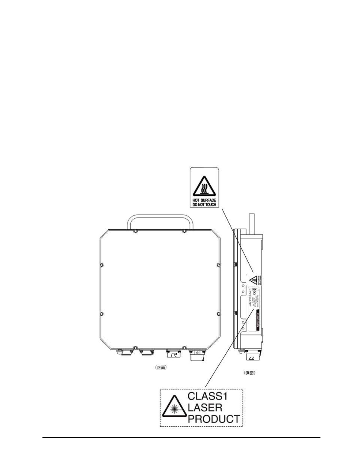
Important
Observe all warnings in the text and on equipment labels regarding high-voltage or high temperature
conditions. The fallowing warnings and figures apply to most FUJITSU product.
Page 7

.
Page 8

The contents of this document are subject to change without notice since Fujitsu Limited reserves the right to make changes
in equipment design or components or firmware release roadmap without notice, as progress in engineering or
manufacturing methods may warrant. Neither this document nor any portion thereof, is to be reproduced in any form
whatsoever without written permission from Fujitsu Limited.
Copyright © 2012 Fujitsu Limited. All Rights Reserved.
Microsoft is a registered trademark of the Microsoft Corporation. Windows is a trademark of the Microsoft Corporation.
All other product names mentioned herein are the trademarks of their respective owners.
Page 9

Fujitsu and Fujitsu Customer Use Only System Description
BroadOne GX4000 Manual (R3.0) issue 1.03 1-1
1 System Description
1.1 Overview
This chapter describes the system description of BroadOne GX4000
E-band Impulse radio. The main topics covered are:
System Overview
Ordering Information
General Specification
Environmental Specification
Power requirement
1.2 System Overview
Two Types of Signal Interface
Fujitsu BroadOne GX4000 series E-band impulse radio is complete
All-In-One ODU radio employing impulse modulation technology.
Two (2) types of signal interfaces are available, one is Ethernet interface
(10GbE and/or 1GbE) and the other is CPRI (Common Public Radio
Interface) (*1) interface for mobile communication.
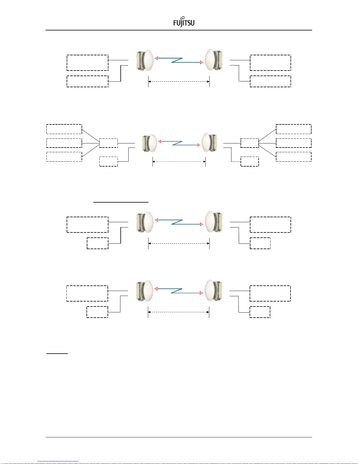
Ethernet Interface
Figure 1.1a Ether System-1 (10GbE Optical Interface)
Figure 1.1b Ether System-2 (1GbE Electrical Interface)
70GHz/80 GHz
5 GHz Bandwidth
10GBASE-LR
Network Equipment
10GBASE-LR
Network Equipment
10GbE
Optical
Ethernet: 3.0 Gbit/s
Local
Terminal
10GbE
Optical
70GHz/80 GHz
5 GHz Bandwidth
1GbE
Electrical
1GbE
Electrical
1000BASE-T
Network Equipment
1000BASE-T
Network Equipment
Ethernet: 3.0 Gbit/s
Page 10
System Description Fujitsu and Fujitsu Customer Use Only
1-2 BroadOne GX4000 Manual (R3.0) issue 1.03
Figure 1.1c Ether System-3 (10GbE Optical & 1GbE Electrical Interface)
Figure 1.1d Ethernet System-4 (L2SW Interface)
CPRI Interface (*1)
Figure 1.1e CPRI Interface
Figure 1.1f CPRI Interface
Note-*1:
The Common Public Radio Interface (CPRI™) is the successful industry cooperation defining the
publicly available specification for the key internal interface of radio base stations between the Radio
Equipment Control (REC) and the Radio Equipment (RE). The Parties cooperating to define the CPRI
Specification are now encompassing Ericsson, Huawei, NEC, Nokia Siemens Networks and AlcatelLucent. Nortel contributed as member of the CPRI cooperation to CPRI Specification versions 1.4, 2.1,
3.0 4.0 and 4.1 and left the cooperation in December 2009
BBU: Base Band Unit for Japan domestic market
RRH: Remote Radio Head for Japan domestic market
70GHz/80 GHz
5 GHz Bandwidth
10GbE
Optical
10GbE
Optical
1000BASE-T
Network Equipment
1000BASE-T
Network Equipment
Ethernet: 3.0 Gbit/s
1000BASE-T
Network Equipment
1000BASE-T
Network Equipment
1GbE
Electrical
1GbE
Electrical
70GHz/80 GHz
5 GHz Bandwidth
Baseband Unit
(BBU)
Remote Radio Head
(RRH)
Local
Terminal
2.4576 Gbit/s (CPRI)
CPRI
2.4576 Mbit/s
Local
Terminal
5 GHz Bandwidth
CPRI
Optical
Radio Equipment
Control (REC)
Remote Radio
Equipment (RRE)
Local
Terminal
2.4576 Gbit/s (CPRI)
Local
Terminal
CPRI
Optical
70GHz/80 GHz
5 GHz Bandwidth
Local
Terminal
1000BASE-LX
Network Equipment
1000BASE-LX
Network Equipment
1000BASE-LX
Network Equipment
1000BASE-LX
Network Equipment
1000BASE-LX
Network Equipment
Ethernet: 3.0 Gbit/s
L2SW
Local
Terminal
L2SW
10GbE
Optical
1GbE
Electrical
1000BASE-LX
Network Equipment
Page 11

Fujitsu and Fujitsu Customer Use Only System Description
BroadOne GX4000 Manual (R3.0) issue 1.03 1-3
Features & Performance
Wireless Innovation based on Impulse Radio
70/80 GHz E-Band 1+0 point-to-point radio
Lightweight, small size zero-footprint ODU design
< 3.0 litter and < 3.0 kg
High power amplifier using GaAs Field Effect Transistor (GaAs FET)
Low power consumption (< 20 W / 1+0)
High Capacity Radio
- 3,000 Mbit/s for Ethernet interface
- 2,457.6 Mbit/s for CPRI interface (4 x 614.4 Mbit/s)
Low latency for multimedia application
Transmit Power Control (ATPC/MTPC) available
Read Solomon error correction
Web-based local terminal and EMS compatible SNMP
1-feet or 2-feet cassegrain antenna with fixing material to pole
Application
LTE/WiMAX Backhaul
Fiber Extension
Mobile Backhaul
Local Area Network Extension
Metropolitan Area Networks (MAN)
Page 12
System Description Fujitsu and Fujitsu Customer Use Only
1-4 BroadOne GX4000 Manual (R3.0) issue 1.03
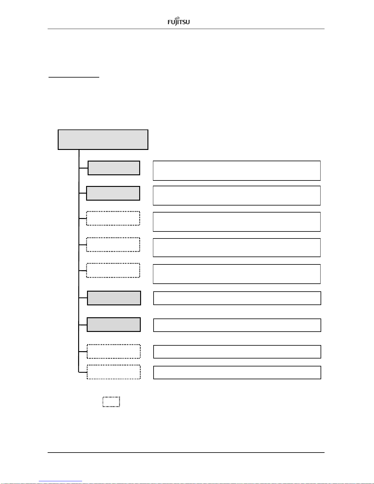
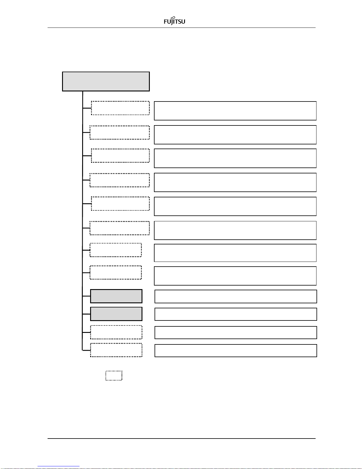
1.3 Ordering Information
Ordering Guide
< Configuration Tree of GX4000 System per Link >
: Optional item
Figure 2.1a Configuration Tree for Ethernet Interface & DC Feed
L2SW
70G Ether DC
GX4000 System
Ether interface, DC
: 70G GX4000 for Ether for station A (B): x 1
Signal interface: 10GBASE-LR & 1000BASE-T
80G Ether DC
: 80G GX4000 for Ether for station B (A): x 1
Signal interface: 10GBASE-LR & 1000BASE-T
: L2 Switch module : x 1
Max. 3 1000BASE-LX to 10GBASE-LR
1-feet Antenna
: 1-feet cassegrain antenna with fixing materials to pole : x 1
Direct connection with radio equipment without feeder
2-feet Antenna
: 2-feet cassegrain antenna with fixing materials to pole : x 1
Direct connection with radio equipment without feeder
: DC power cable: x 2
Signal Cable
: Ethernet (electrical or optical) and IO cable: x 1 set
Connector
: Connector for DC power, IO & criping terminal: x 1 set
Power Cable
Optional
: Optional such as Instruction manual & test stand : x 1 set
Page 13

Fujitsu and Fujitsu Customer Use Only System Description
BroadOne GX4000 Manual (R3.0) issue 1.03 1-5
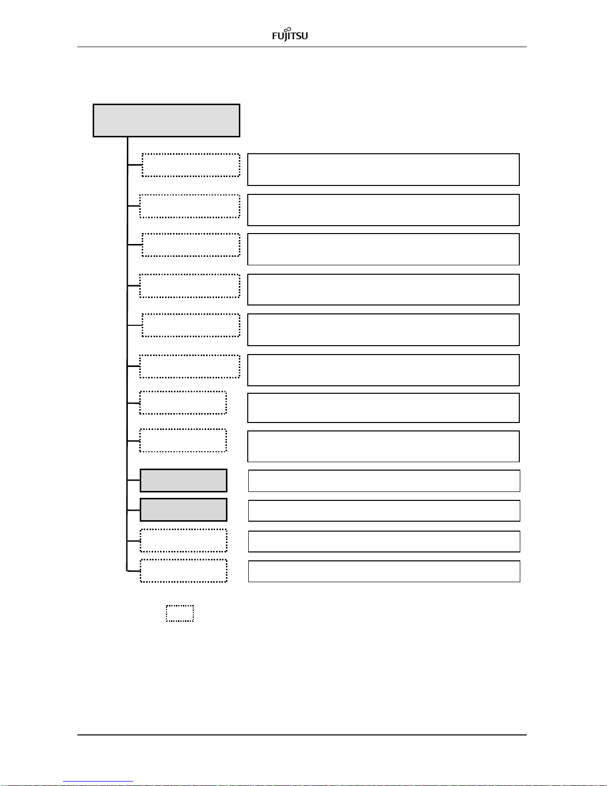
: Optional
Figure 2.1b Configuration Tree for Ethernet Interface & AC Feed
L2SW
70G Ether AC
GX4000 System
Ether interface, AC
: 70G E-band IR for Ether for station A (B): x 1
Signal interface: 10GBASE-LR & 1000BASE-T
80G Ether AC
: 80G E-band IR for Ether for station B (A): x 1
Signal interface: 10GBASE-LR & 1000BASE-T
: L2 Switch module : x 1
Max. 3 1000BASE-LX to 10GBASE-LR
1-feet Antenna
: 1-feet cassegrain antenna with fixing materials to pole : x 1
Direct connection with radio equipment without feeder
2-feet Antenna
: 2-feet cassegrain antenna with fixing materials to pole : x 1
Direct connection with radio equipment without feeder
: AC power cable: x 2
Signal Cable
: Ethernet (electrical or optical) and IO cable: x 1 set
Connector
: Connector for AC power, IO & criping terminal: x 1 set
Power Cable
Optional
: Optional such as Instruction manual & test stand : x 1 set
Page 14
System Description Fujitsu and Fujitsu Customer Use Only
1-6 BroadOne GX4000 Manual (R3.0) issue 1.03
: Optional item
Figure 2.1c Configuration Tree for CPRI Interface & DC Feed
70G CPRI BBU
GX4000 System
CPRI interface, DC
: 70G E-band IR for CPRI BBU for station A (B): x 1
User rate: 2,4576 Mbit/s
80G CPRI RRH
: 80G E-band IR for CPRI RRH for station B (A): x 1
User rate: 2,4576 Mbit/s
1-feet Antenna
: 1-feet cassegrain antenna with fixing materials to pole : x 1
Direct connection with radio equipment without feeder
2-feet Antenna
: 2-feet cassegrain antenna with fixing materials to pole : x 1
Direct connection with radio equipment without feeder
: DC power cable: x 2
Signal Cable
: Signal cable for optical CPRI & IO cable: x 1 set
Connector
: Cnnector for DC power, IO & crimping terminal: x 1 set
80G CPRI BBU
: 80G E-band IR for CPRI BBU station A (B): x 1
User rate: 2,4576 Mbit/s
70G CPRI RRH
: 70G E-band IR for CPRI RRH for station B (A): x 1
User rate: 2,4576 Mbit/s
Power Cable
Optional
: Optional such as instruction manual & test stand: x 1 set
70G CPRI MMF
: 80G E-band IR for CPRI MMF station A (B): x 1
User rate: 2,4576 Mbit/s
80G CPRI MMF
: 70G E-band IR for CPRI MMF for station B (A): x 1
User rate: 2,4576 Mbit/s
Page 15
Fujitsu and Fujitsu Customer Use Only System Description
BroadOne GX4000 Manual (R3.0) issue 1.03 1-7
: Optional item
Figure 2.1d Configuration Tree for CPRI Interface & AC Feed
70G CPRI BBU
GX4000 System
CPRI interface, AC
: 70G E-band IR for CPRI BBU for station A (B): x 1
User rate: 2,4576 Mbit/s
80G CPRI RRH
: 80G E-band IR for CPRI RRH for station B (A): x 1
User rate: 2,4576 Mbit/s
1-feet Antenna
: 1-feet cassegrain antenna with fixing materials to pole : x 1
Direct connection with radio equipment without feeder
2-feet Antenna
: 2-feet cassegrain antenna with fixing materials to pole : x 1
Direct connection with radio equipment without feeder
: AC power cable: x 2
Signal Cable
: Signal cable for optical CPRI & IO cable: x 1 set
Connector
: Cnnector for AC power, IO & crimping terminal: x 1 set
80G CPRI BBU
: 80G E-band IR for CPRI BBU station A (B): x 1
User rate: 2,4576 Mbit/s
70G CPRI RRH
: 70G E-band IR for CPRI RRH for station B (A): x 1
User rate: 2,4576 Mbit/s
Power Cable
Optional
: Optional such as instruction manual & test stand: x 1 set
70G CPRI MMF
: 80G E-band IR for CPRI MMF station A (B): x 1
User rate: 2,4576 Mbit/s
80G CPRI MMF
: 70G E-band IR for CPRI MMF for station B (A): x 1
User rate: 2,4576 Mbit/s
Page 16
System Description Fujitsu and Fujitsu Customer Use Only
1-8 BroadOne GX4000 Manual (R3.0) issue 1.03
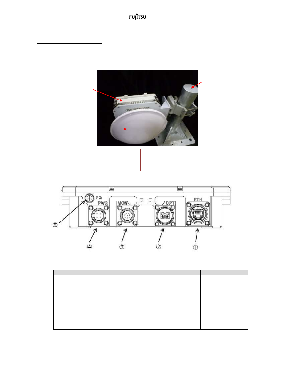
Mechanical Configuration
To introduce the GX4000 system, it is necessary to select equipment, proper materials
and cables regarding to the Application Code. Table 2.1 shows the code.
Mounting Pole
GX4000
Optical cable for 10GbE or CPRI interface,
LAN cable & DC/AC power supply / ALM cable
Mechanical Connection of GX4000
No
Indication
Cable
Description
Cable
1
ETH
RJ-45
1GbE electrical or
maintenance port
Ether cable
2
OPT
Ether: 2xLC
CPRI 1-core: 1xSC
CPRI 2-core: 2xLC
Optical IN/OUT
Optical cable
3
MON
Round 8P
Housekeeping
RSL monitoring
IO cable
Monitor cable
4
PWR
DC: Round 4P
AC: Round 3P
DC -48 V
AC: 100 to 240 V
DC power cable
AC power cable
5
FG
M8 bolt
Frame ground
Cassegrain antenna
with antenna fixing
material to pole
Page 17

Fujitsu and Fujitsu Customer Use Only System Description
BroadOne GX4000 Manual (R3.0) issue 1.03 1-9
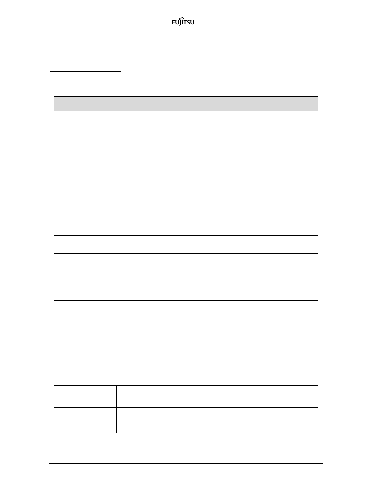
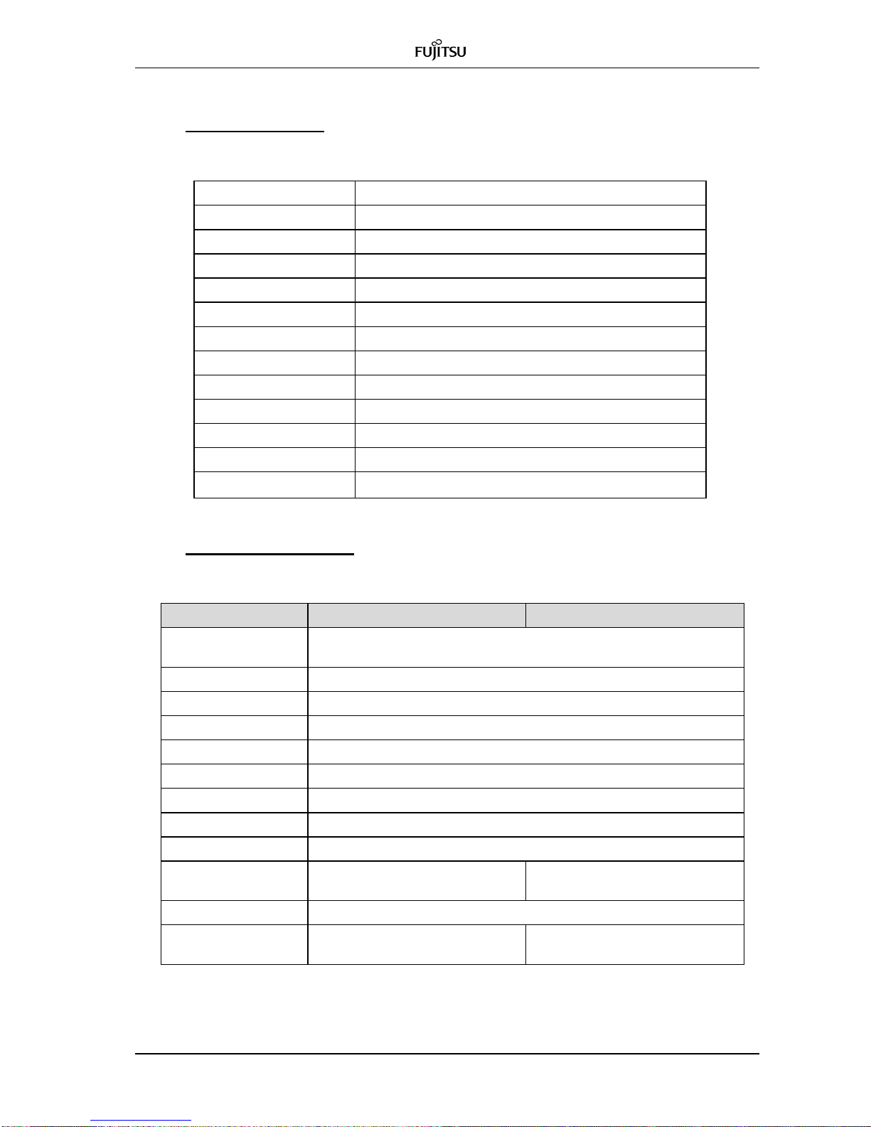
Ordering Code
Table 2.1a Code for GX4000 Equipment
Description
Ordering Code
GX4000 Ether 70G DC
TX=70 GHz & RX=80 GHz band
Ethernet interface, 3.0 Gbps,
2-SMF, DC -48 V
GX4380LE3D
GX4000 Ether 80G DC
TX=80 GHz & RX=70 GHz band
Ethernet interface, 3.0 Gbps
2-SMF, DC -48 V
GX4380UE3D
GX4000 CPRI BBU 70G DC
TX=70 GHz & RX=80 GHz band
CPRI BBU interface, 2.4576 Gbps
1-SMF, DC -48 V
GX4380LB3D
GX4000 CPRI RRH 80G DC
TX=80 GHz & RX=70 GHz band
CPRI RRH interface, 2.4576 Gbps
1-SMF, DC -48 V
GX4380UB3D
GX4000 CPRI BBU 80G DC
TX=80 GHz & RX=70 GHz band
CPRI BBU interface, 2.4576 Gbps
1-SMF, DC -48 V
GX4380UB3D
GX4000 CPRI RRH 70G DC
TX=80 GHz & RX=70 GHz band
CPRI RRH interface, 2.4576 Gbps
1-SMF, DC -48 V
GX4380LR3D
GX4000 CPRI MMF 70G DC
TX=70 GHz & RX=80 GHz band
CPRI MMF interface, 2.4576 Gbps
2-MMF, DC -48 V
GX4380UC3D
GX4000 CPRI MMF 80G DC
TX=80 GHz & RX=70 GHz band
CPRI MMF interface, 2.4576 Gbps
2-MMF, DC -48 V
GX4380LC3D
GX4000 Ether 70G AC
TX=70 GHz & RX=80 GHz band
Ether interface, 3.0 Gbps
2-SMF, AC 100 - 240 V
GX4380LE3A
GX4000 Ether 80G AC
TX=80 GHz & RX=70 GHz band
Ether interface, 3.0 Gbps
2-SMF, AC 100 - 240 V
GX4380UE3A
GX4000 CPRI BBU 70G AC
TX=70 GHz & RX=80 GHz band
CPRI BBU interface, 2.4576 Gbps
1-SMF, AC 100 – 240 V
GX4380LB3A
GX4000 CPRI RRH 80G AC
TX=80 GHz & RX=70 GHz band
CPRI RRH interface, 2.4576 Gbps
1-SMF, AC 100 – 240 V
GX4380UR3A
E-band CPRI BBU 80G AC
TX=80GHz & RX=70 GHz band
CPRI BBU interface, 2.4576 Gbps
1-SMF, AC100 to 240 V
GX4380UB3A
E-band CPRI RRH 70G AC
TX=70 GHz & RX=80 GHz band
CPRI RRH interface, 2.4576 Gbps
1-SMF, AC 100 to 240 V
GX4380LR3A
GX4000 CPRI MMF 70G AC
TX=70 GHz & RX=80 GHz band
CPRI interface, 2.4576 Gbps
2-MMF, AC 100 – 240 V
GX4380UC3A
GX4000 CPRI MMF 80G AC
TX=80 GHz & RX=70 GHz band
CPRI interface, 2.4576 Gbps
2-MMF, AC 100 – 240 V
GX4380LC3A
Page 18

System Description Fujitsu and Fujitsu Customer Use Only
1-10 BroadOne GX4000 Manual (R3.0) issue 1.03
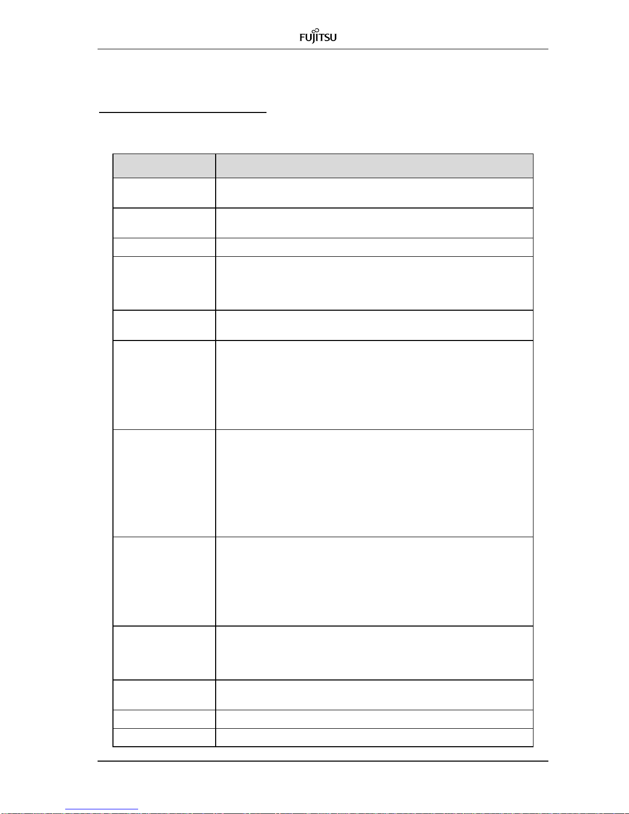
Table 2.1b Code for Antenna
Description
Ordering Code
Cassegrain Antenna, 1-feet
1-feet antenna
Direct connection to GX4000
Including mounting kit
GX4K80ATP11
Cassegrain Antenna, 2-feet
1-feet antenna
Direct connection to GX4000
Including mounting kit
GX4K80ATP12
Table 2.1c Code for DC Power Cable
Description
Ordering Code
DC Power cable, 1 m
DC power supply cable, 1 m
GX4K80CBPD01
DC Power cable, 5 m
DC power supply cable, 5 m
GX4K80CBPD05
DC Power cable, 10 m
DC power supply cable, 10 m
GX4K80CBPD10
DC Power cable, 20 m
DC power supply cable, 20 m
GX4K80CBPD20
DC Power cable, 30 m
DC power supply cable, 30 m
GX4K80CBPD30
DC Power cable, 40 m
DC power supply cable, 40 m
GX4K80CBPD40
DC Power cable, 50 m
DC power supply cable, 50 m
GX4K80CBPD50
DC Power cable, 60 m
DC power supply cable, 60 m
GX4K80CBPD60
DC Power cable, 70 m
DC power supply cable, 70 m
GX4K80CBPD70
DC Power cable, 80 m
DC power supply cable, 80 m
GX4K80CBPD80
DC Power cable, 90 m
DC power supply cable, 90 m
GX4K80CBPD90
DC Power cable, 100 m
DC power supply cable, 100 m
GX4K80CBPD99
Table 2.1d Code for AC Power Cable
Description
Ordering Code
AC Power cable, 1 m
AC power supply cable, 1 m
GX4K80CBPA01
AC Power cable, 5 m
AC power supply cable, 5 m
GX4K80CBPA05
AC Power cable, 10 m
AC power supply cable, 10 m
GX4K80CBPA10
AC Power cable, 20 m
AC power supply cable, 20 m
GX4K80CBPA20
AC Power cable, 30 m
AC power supply cable, 30 m
GX4K80CBPA30
AC Power cable, 40 m
AC power supply cable, 40 m
GX4K80CBPA40
AC Power cable, 50 m
AC power supply cable, 50 m
GX4K80CBPA50
AC Power cable, 60 m
AC power supply cable, 60 m
GX4K80CBPA60
AC Power cable, 70 m
AC power supply cable, 70 m
GX4K80CBPA70
AC Power cable, 80 m
AC power supply cable, 80 m
GX4K80CBPA80
AC Power cable, 90 m
AC power supply cable, 90 m
GX4K80CBPA90
AC Power cable, 100 m
DC power supply cable, 100 m
GX4K80CBPA99
Page 19

Fujitsu and Fujitsu Customer Use Only System Description
BroadOne GX4000 Manual (R3.0) issue 1.03 1-11
Table 2.1e Code for Ether Electrical Cable
Description
Ordering Code
Ether electrical cable, 1 m
Ether cable, 1 m
GX4K80CBET01
Ether electrical cable, 5 m
Ether cable, 5 m
GX4K80CBET05
Ether electrical cable, 10 m
Ether cable, 10 m
GX4K80CBET10
Ether electrical cable, 20 m
Ether cable, 20 m
GX4K80CBET20
Ether electrical cable, 30 m
Ether cable, 30 m
GX4K80CBET30
Ether electrical cable, 40 m
Ether cable, 40 m
GX4K80CBET40
Ether electrical cable, 50 m
Ether cable, 50 m
GX4K80CBET50
Ether electrical cable, 60 m
Ether cable, 60 m
GX4K80CBET60
Ether electrical cable, 70 m
Ether cable, 70 m
GX4K80CBET70
Ether electrical cable, 80 m
Ether cable, 80 m
GX4K80CBET80
Ether electrical cable, 90 m
Ether cable, 90 m
GX4K80CBET90
Table 2.1f Code for IO Cable
Description
Ordering Code
IO cable, 1 m
IN/OUT cable, 1 m
GX4K80CBAL01
IO cable, 5 m
IN/OUT cable, 5 m
GX4K80CBAL05
IO cable, 10 m
IN/OUT cable, 10 m
GX4K80CBAL10
IO cable, 20 m
IN/OUT cable, 20 m
GX4K80CBAL20
IO cable, 30 m
IN/OUT cable, 30 m
GX4K80CBAL30
IO cable, 40 m
IN/OUT cable, 40 m
GX4K80CBAL40
IO cable, 50 m
IN/OUT cable, 50 m
GX4K80CBAL50
IO cable, 60 m
IN/OUT cable, 60 m
GX4K80CBAL60
IO cable, 70 m
IN/OUT cable, 70 m
GX4K80CBAL70
IO cable, 80 m
IN/OUT cable, 80 m
GX4K80CBAL80
IO cable, 90 m
IN/OUT cable, 90 m
GX4K80CBAL90
IO cable, 100 m
IN/OUT cable, 100 m
GX4K80CBAL99
Table 2.1g Code for Ether Optical Cable
Description
Ordering Code
Ether optical cable, 1 m
2-SMF, single mode, 1 m
GX4K80CB2S01
Ether optical cable, 5 m
2-SMF, single mode, 5 m
GX4K80CB2S05
Ether optical cable, 10 m
2-SMF, single mode, 10 m
GX4K80CB2S10
Ether optical cable, 20 m
2-SMF, single mode, 20 m
GX4K80CB2S20
Ether optical cable, 30 m
2-SMF, single mode, 30 m
GX4K80CB2S30
Ether optical cable, 40 m
2-SMF, single mode, 40 m
GX4K80CB2S40
Ether optical cable, 50 m
2-SMF, single mode, 50 m
GX4K80CB2S50
Ether optical cable, 60 m
2-SMF, single mode, 60 m
GX4K80CB2S60
Ether optical cable, 70 m
2-SMF, single mode, 70 m
GX4K80CB2S70
Ether optical cable, 80 m
2-SMF, single mode, 80 m
GX4K80CB2S80
Ether optical cable, 90 m
2-SMF, single mode, 90 m
GX4K80CB2S90
Ether optical cable, 100 m
2-SMF, single mode, 100 m
GX4K80CB2S99
Page 20

System Description Fujitsu and Fujitsu Customer Use Only
1-12 BroadOne GX4000 Manual (R3.0) issue 1.03
Table 2.1h Code for CPRI 1-SMF Optical Cable
Description
Ordering Code
CPRI optical cable,1 m
CPRI, 1-SMF, single mode, 1 m
GX4K80CB1S01
CPRI optical cable,5 m
CPRI, 1-SMF, single mode, 5 m
GX4K80CB1S05
CPRI optical cable,10 m
CPRI, 1-SMF, single mode, 10 m
GX4K80CB1S10
CPRI optical cable,20 m
CPRI, 1-SMF, single mode, 20 m
GX4K80CB1S20
CPRI optical cable,30 m
CPRI, 1-SMF, single mode, 30 m
GX4K80CB1S30
CPRI optical cable,40 m
CPRI, 1-SMF, single mode, 40 m
GX4K80CB1S40
CPRI optical cable,50 m
CPRI, 1-SMF, single mode, 50 m
GX4K80CB1S50
CPRI optical cable,60 m
CPRI, 1-SMF, single mode, 60 m
GX4K80CB1S60
CPRI optical cable,70 m
CPRI, 1-SMF, single mode, 70 m
GX4K80CB1S70
CPRI optical cable,80 m
CPRI, 1-SMF, single mode, 80 m
GX4K80CB1S80
CPRI optical cable,90 m
CPRI, 1-SMF, single mode, 90 m
GX4K80CB1S90
CPRI optical cable,100 m
CPRI, 1-SMF, single mode, 100 m
GX4K80CB1S99
Table 2.1i Code for CPRI 2-SMF Optical Cable
Description
Ordering Code
CPRI optical cable,1 m
CPRI, 2-SMF, multi mode, 1 m
GX4K80CB2M01
CPRI optical cable,5 m
CPRI, 2-SMF, multi mode, 5 m
GX4K80CB2M05
CPRI optical cable,10 m
CPRI, 2-SMF, multi mode, 10 m
GX4K80CB2M10
CPRI optical cable,20 m
CPRI, 2-SMF, multi mode, 20 m
GX4K80CB2M20
CPRI optical cable,30 m
CPRI, 2-SMF, multi mode, 30 m
GX4K80CB2M30
CPRI optical cable,40 m
CPRI, 2-SMF, multi mode, 40 m
GX4K80CB2M40
CPRI optical cable,50 m
CPRI, 2-SMF, multi mode, 50 m
GX4K80CB2M50
CPRI optical cable,60 m
CPRI, 2-SMF, multi mode, 60 m
GX4K80CB2M60
CPRI optical cable,70 m
CPRI, 2-SMF, multi mode, 70 m
GX4K80CB2M70
CPRI optical cable,80 m
CPRI, 2-SMF, multi mode, 80 m
GX4K80CB2M80
CPRI optical cable,90 m
CPRI, 2-SMF, multi mode, 90 m
GX4K80CB2M90
CPRI optical cable,100 m
CPRI, 2-SMF, multi mode, 100 m
GX4K80CB2M99
Page 21

Fujitsu and Fujitsu Customer Use Only System Description
BroadOne GX4000 Manual (R3.0) issue 1.03 1-13
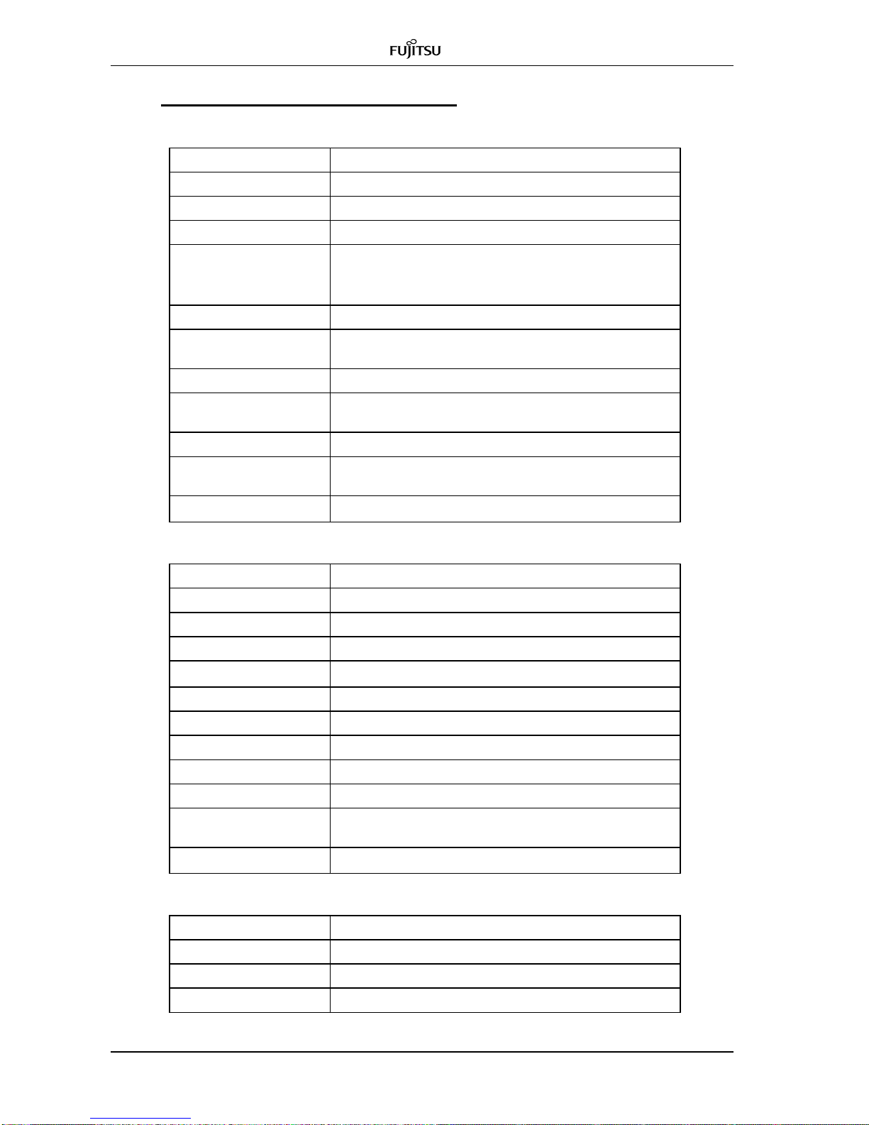
Table 2.1j Code for DC Power Connector
Description
Ordering Code
DC power connector
4P connector
GX4K80CNPD
Table 2.1k Code for AC Power Connector
Description
Ordering Code
AC power connector
3P connector
GX4K80CNPA
Table 2.1l Code for IO Connector
Description
Ordering Code
IO connector
8P connector
GX4K80CNHK
Table 2.1m Code for Crimping Connector
Description
Ordering Code
Crimping terminal
M8 crimping terminal
GX4K80CNFG
Table 2.1n Code for Optional Materials
Description
Ordering Code
Installation kit
Installation manual, paper media
GX4K80MNJAP
Installation kit
Installation manual, soft media
GX4K80MNJAC
Monitor cable
Monitor cable for RSL monitoring
GX4K80CBMT
Test stand
Test stand on table
GX4K80TFTS
Test stand kit
Test stand on table x2
GX4K80TFTS2
Fixing material for telescope
Material for antenna orientation
GX4K80ADMK
Telescope
Telescope for antenna orientation
GX4K80ADSD
Sighting device
Sighting device for antenna
orientation
GX4K80ADSSD
Table 2.1o Code for Optional L2SW Module
Description
Ordering Code
L2SW
L2 switch module
SJ324TC113
10G expansion module
10G expansion module
SJ10GXFPA
10G optical module
10G optical module
SJXFPLR
1G optical module
1G optical module
SJSFPLX
Page 22
System Description Fujitsu and Fujitsu Customer Use Only
1-14 BroadOne GX4000 Manual (R3.0) issue 1.03
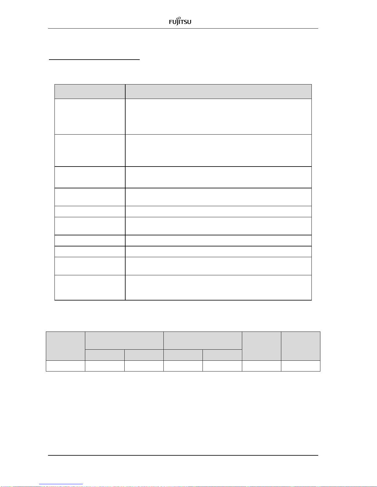
1.4 General Specifications
System Specification
Table 1.4-1 System Specification
Item
Description
RF Band Used
70/80 GHz band (E-Band)
in accordance with ETSI EN302 217-3 V1.3.1 (2009-07) Annex UC
70 GHz band: 71,0 to 76.0 MHz
80 GHz band: 81,0 to 86.0 MHz
Occupied
Bandwidth
Less than 5,000 MHz
Transmission
Capacity
Digital Transfer rate:
In case of Ether interface: 3,000 Mbit/s
In case of CPRI interface: 2,457.6 Mbit/s
Total digital transfer rate:
70 GHz band: 3,266.786 Mbit/s
80 GHz band: 3,274.286 Mbit/s
Radio Symbol Rate
70 GHz band: 3,266.786 MHz
80 GHz band: 3,274.286 MHz
System
Configuration
1+0, Terminal configuration
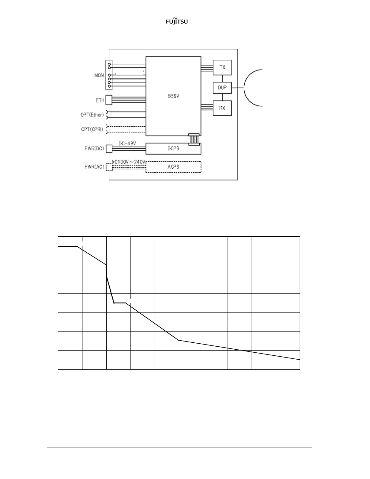
Block diagram of GX4000 is shown in Figure 1.4-1.
TX Power Output
0 to +10 dBm measured at Point C’ (antenna port)
in accordance with ETSI EN302 217-1 V1.2.1 (2007-06)
TX Output Control
ATPC/MTPC
Received RF Input
Minimum RSL: -54 dBm typical at BER of 10-6
Maximum RSL: -25 dBm typical at BER of 10-6
AGC range: -56 to -25 dBm
measured at Point C (antenna port) in accordance with ETSI EN302
217-1 V1.2.1 (2007-06)
Modulation
OOK (ON-OFF-Keying)
Error Correction
Reed Solomon (255/239) with Bit Interleave function
Route ID
0 to 15, pre-settable
Baseband Interface
(1) 10GBASE-LR and/or 1000BASE-T or
(2) CPRI or
(3) CPRI BBU for Base Band Unit interface or
(4) CPRI RRH for Remote Radio Head interface
DC Power Supply
DC -48 Vdc (-40.5 to -57 Vdc)
AC 100 to 240 V, 50/60 Hz
Power Consumption
25 W typical, 30 W guaranteed
Dimension
230 x 230 x 56 mm excluding protrusions
Weight
GX4000: < 3 kg
1-feet antenna with fixing materials to pole: < 10 kg
2-feet antenna with fixing materials to pole: < 14 kg
Page 23
Fujitsu and Fujitsu Customer Use Only System Description
RroadOne GX4000 Manual (R3.0) issue 1.03 1-15
Transmitter Side Specification
Table 1.4-2 Transmitter Part
Item
Description
RF Output Power
0 to +10 dBm measured at antenna port
RF output power tolerance: -3.0 / +0.8 dB
RF Output Power
when set TX OFF
< -40 dBm
CW/MOD Selection
None
RF Band used and
RF equivalent
center frequency
70/80 GHz band (E-band)
in accordance with ETSI EN302 217-3 V1.3.1 (2009-07) Annex UC
70 GHz band: 71,125 to 75,625 MHz (f0 = 73,503 GHz)
80 GHz band: 81,125 to 85,625 MHz (f0 = 83,494 GHz)
Output Power
Density Mask
In accordance with ETSI EN 302 217-3 V1.3.1 (2009-07) Annex-UC
measured at antenna port as shown in Figure 1.4-2a.
Emission Outside
the 71-76 GHz &
8.1-86 GHz Range
(1) Output power spectral density, at antenna port, falling outside of
the 71-76 GHz band edge or below the lower band edge of 81-86
GHz band should be limited to a maximum of -55 dBW/MHz.
(2) For the band 86-92 GHz is allocated to Passive Services and, in
particular to Earth Extension Satellite Services, for their protection,
unwanted emission power density at the antenna port is in
accordance with Figure 1.4-2b.
TX Spurious
Emission - External
In accordance with ETSI EN301 390 V1.2.1 (2003-11)
For the interference into other systems operation for the fundamental
frequency range of 13 GHz to 150 GHz band, spurious emission
allowable is shown in Figure 1.4-2c.
(a) < -50 dBm in the frequency range of 30 MHz to 21.2 GHz
(b) < -30 dBm in the frequency range of 21.2 GHz to 2nd harmonic
Spurious emission is defined as any emission at frequencies which
are outside the nominal carrier frequency by more than +/- 250% of
the aggregated channel separation (4,500 MHz of 70/80 GHz band).
ATPC
Automatic transmit power control (ATPC) is available as standard.
Power control level: 0 to +10 dBm, continuous
Initiation threshold: Normal RSL +/- 3 dB
Restoration threshold; Normal RSL +/- 2 dB
Response time: 20 dB/sec
Control initiator: Pre-settable Received signal Level (RSL)
Pre-settable RSL: -30 dBm or -40 dBm
MTPC
Manual transmit power control (MTPC) is available as standard.
Power control level: 0 to 10 dB, 0.5-dB step
Output level variation: +/- 0.5 dB
Control: Manual
Symbol Rate
70 GHz (Lower band): 3,266.786 Mbit/s
80 GHz (Upper band): 3.274.286 Mbit/s
RF Output VSWR
Less than 1.5 measured at antenna port
RF Connector
UG-387 / U (flange)
Page 24
System Description Fujitsu and Fujitsu Customer Use Only
1-16 BroadOne GX4000 Manual (R3.0) issue 1.03
Figure 1.4-1 Schematic Block Diagram of GX4000
Figure 1.4-2a Output Power Density Mask
(In accordance with ETSI EN 302 217-3 V1.3.1 (2009-07) Annex UC
0%/-15 20%/-15
50%/-25
50%/-30
57.5%/-45
70%/-45
125%/-65
-80
250%
Frequency Offset from Center of Frequency relative to aggregated channel
TX Output Power Density Mask
-40
-50
50%
150%
0%
-10
Power Density (dBW / MHz)
-60
-70
-20
-30
200%
100%
Page 25

Fujitsu and Fujitsu Customer Use Only System Description
RroadOne GX4000 Manual (R3.0) issue 1.03 1-17
Figure 1.4-2b Unwanted Emission Power Density at the Antenna port
(In accordance with ETSI EN 302 217-3 V1.3.1 (2009-07) Annex UC
Parameter
Description
Remarks
CS
Aggregation channel spacing
4.5 GHz
F0
Equivalent RF center frequency
73.503 GHz (lower)
83.494 GHz (upper)
F0-CSx2.5
Edge of output power density mask
62.253 GHz (lower)
72.244 GHz (upper)
F0+CSx2.
5
Edge of output power density mask
84.753 GHz (lower)
94.744 GHz (upper)
2 x F0
Second harmonic
147.0054 GHz (lower)
166.9886 GHz (upper)
TX spurious specification according to EN301 390 V1.2.1 (2003-11)
Spurious Range
Frequency Range
Specification
External
30 MHz to 21.2 GHz
<-50 dBm
21.2 GHz to 2nd Harmonic
<-30 dBm
Figure 1.4-2c Spurious Emission - External at the Antenna port
(In accordance with ETSI EN 301 390-3 V1.2.1 (2003-11)
90
-35
-40
-41
-45
-50
-55
91
92
Frequency (GHz)
Power Dendity (dBW/100 MHz)
-60
868788
89
f0+CS×250%
f0-CS×250%
f0
-30dBm/MHz
-30dBm/MHz
21.2GHz
-50dBm/MHz
30MHz
2f0+CS×50%
スペクトラムマス
30 MHz 21.2 GHz F0-CSx250% F0 F0+CSx250% 2xF0
-50 dBm/MHz
-30 dBm/MHz
-30 dBm/MHz
GX4000 Power Density
Mask
Aggregation Channel
(CS=4.5 GHz)
Page 26
System Description Fujitsu and Fujitsu Customer Use Only
1-18 BroadOne GX4000 Manual (R3.0) issue 1.03
Receiver Side Specification
Table 1.4-3 Receiver Part
Item
Description
Noise Figure
11.5 dB typical
12 dB guaranteed
Noise figure is measured at Point C (antenna port) in accordance
with ETSI EN302 217-1 (2007-06) & at maximum gain of RF AMP.
RX RF Band
70/80 GHz band (E-band)
in accordance with ETSI EN302 217-3 V1.3.1 (2009-07) Annex UC
70 GHz band: 71,125 to 75,625 MHz
80 GHz band: 81,125 to 85,625 MHz
RX Spurious Emission
<-10 dBm / MHz for out band emission frequency range
<-13 dBm / MHz for spurious emission frequency range
Normal Received
Power
–54 to –25 dBm at Point C and BER of 10
-6
AGC Dynamic Range
–56 to –25 dBm
Allowable TX-RX
Interference Level
<-79 dBm when RSL is -54 dBm
RF Interference
In accordance with Table 1.4-3
RX Input VSWR
Less than 1.5 measured at antenna port
Alarm Function
(1) RX Block Failure
(2) RSL Abnormal
Monitoring
(1) Analogue monitor for antenna orientation (0 to 3.3 V)
(2) RSL monitor on WebLT (Level variation: +/- 3 dB)
(3) Inner temperature monitoring (-33 to +85 degree)
Table 1.4-4 RF Interference Sensitivity
Co-CH Interference
First Adjacent CH
Interference
CW
Remarks
1 dB deg.
3 dB deg.
1 dB deg.
3 dB deg.
C/I
23
19 0 -4
-30
Note: CW: > f0 +/- CS x 250 %
Page 27
Fujitsu and Fujitsu Customer Use Only System Description
RroadOne GX4000 Manual (R3.0) issue 1.03 1-19
Transmit-Receive Overall Performance
Table 1.4-5 BER Performance Overall
Item
Description
Upfade BER
BER = 10–6 at RSL of –25 dBm typical
BER = 10–6 at RSL of –28 dBm guaranteed
measured at antenna RF input port
Downfade BER
BER = 10–6 at RSL of –54 dBm typical
BER = 10
–6
at RSL of –50.7 dBm guaranteed
measured at antenna RF input port
Residual BER
BER < 10
–12
/hop/day at normal receiving condition (Typical)
BER < 10
–11
/hop/day at normal receiving condition
(Guaranteed)
Signal Interface
Ethernet 10GbE Optical Interface
Table 1.4-6 10GBASE-LR Optical Interface
SFP Used
10G Gigabit Ethernet optical transceiver
Specification
IEEE802.3ae
Transmission Speed
10.3125 Gbit/s
Transmission Capacity
3,000 Mbit/s
Optical Fiber used
1.31 μm single-mode fiber
Optical Fiber Wavelength
1.260 to 1.355 nm
Output Level (average)
-10.2 to +1.5 dBm on XFP using 5 m cable
Input Level (average)
-10.6 to +0.5 dBm on XFP using 5 m cable
Typical Reach
10 km (maximum)
Coding Method
64B/66B
Networking
Tag VLAN, Port VLAN
Synchronization
SyncE, not supported IEEE1588
1-hop, One-way Latency
< 60 μsec excluding transmission path
Connector used
LC duplex
Page 28
System Description Fujitsu and Fujitsu Customer Use Only
1-20 BroadOne GX4000 Manual (R3.0) issue 1.03
Ethernet 1GbE Electrical Interface
Table 1.4-7 1000BASE-T Electrical Interface
Specification
IEEE802.3-2008 (10/100/1000BASE-T)
Connector
RJ-45
Channel
1
Transfer speed
10 Mbit/s, 100 Mbit/s, 1,000 Mbit/s
Transmission capacity
10 Mbit/s, 100 Mbit/s, 1,000 Mbit/s
Cable used
CAT5 or higher
Typical reach
Less than 100 m
Transmission mode
Auto negotiation
MDI/MDI-X
Auto MDI-X
CPRI Optical Interface
Table 1.4-8 CPRI Optical Interface
Specification
CPRI specification V5.0 (2011-09-21), optical
Connector
SC connector, x1
Channel
1
Transmission speed
2,457.6 Mbit/s
Transmission capacity
2.457.6 Mbit/s
Optical Fiber used
1.31 μm zero dispersal type, single-mode fiber (SMF)
1.55 μm dispersal shift type, single-mode fiber (DSM)
Operation Wavelength
Up-stream (REC←RE): 1.275 to 1.355 nm
Down-stream (REC→RE): 1.480 to 1.500 nm
Transmit/receive wave division multiplex (WDM)
Output Level (average)
-8 to -2 dBm on XFP using 5 m cable
Input Level (average)
-17 to 0 dBm on XFP using 5 m cable
Typical Reach
20 km (maximum)
Coding Method
8B/10B
Synchronization
Slave Synchronization
1-hop, One-way Latency
< 20 μsec excluding propagation path
Page 29
Fujitsu and Fujitsu Customer Use Only System Description
RroadOne GX4000 Manual (R3.0) issue 1.03 1-21
CPRI MMF Interface
Table 1.4-9 CPRI MMF Interface
Specification
CPRI specification V5.0 (2011-09-21), optical
Connector
LC duplex, 2xLC
Channel
1
Transmission speed
2,457.6 Mbit/s
Transmission capacity
2.457.6 Mbit/s
Optical Fiber used
850 nm multi-mode fiber
Operation Wavelength
840 to 860 nm
Output Level (average)
-8.2 to +0.5 dBm
Input Level (average)
-13.9 to 0 dBm
Typical Reach
20 km (maximum)
Coding Method
8B/10B
Synchronization
Slave Synchronization
1-hop, One-way Latency
< 15 μsec excluding propagation path
Maintenance Interface
Table 1.4-10 Maintenance Interface for Ether
Item
GX4000 Ether
GX4000 CPRI
Local Maintenance
Web server, Supervision/Log management/Configuration setting/ User
administration/File management
EMS Access
SNMP V2c (MIB II and Private MIB)
Connector
RJ-45
No. of CH
1
Transmission
10BASE-T and 100BASE-TX
Cable
Category 5 UTP (Unshielded Twisted Pair)
Transmission length
<100 m
Transmission Mode
Auto-negotiation (10M full/100M full)
MDI/MDI-X
Auto MDI-X
Remote Contact Line
In-band (V-LAN) both Line and
Radio sides
Not applicable for Line side
RFCOH for Radio side
Housekeeping Item
Supervision x3 and Control x1
Time Setting
Auto setting by NTP version 4
(Client) or manual setting
Manual setting by local
maintenance application
Page 30
System Description Fujitsu and Fujitsu Customer Use Only
1-22 BroadOne GX4000 Manual (R3.0) issue 1.03
Recommended L2SW Module Interface
Table 1.4-12a Line Side Interface of L2SW
Line Side Interface
1000BASE-LX, maximum x3 channels
Connector
LC duplex (LCx2)
Transmission Speed
1.25 Gbit/s
Transmission Capacity
1.25 Gbit/s
Optical Fiber Used
62.5 μm multi-mode fiber (MMF) 50
μm multi-mode fiber (MMF) 10
μm single-mode fiber (SMF)
Operation Wavelength
1,270 to 1,355 nm
Output Level (average)
MMF: -11.5 dBm
SMF: -11.0 to -3.0 dBm
Input Level (average)
-19.0 to -3.0 dBm
Typical Reach
MMF: Maximum 500 m
SMF: Maximum 10 km
Coding Method
8B/10B
Networking
Tag VLAN, Port VLAN, QoS(IEEE802.1p (COS)/
TOS(IP Precedence)/DSCP/ACL(IPv4, IPv6)
1-hop, One-way Latency
< 4 μsec, 64 byte frame in accordance with RFC2544
Table 1.4-12b Radio Side Interface of L2SW
Line Side Interface
10GBASE-LR, 1 channel
Connector
LC duplex (LCx2)
Transmission Speed
10.3125 Gbit/s
Transmission Capacity
10.3125 Gbit/s
Optical Fiber Used
1.31 μm single-mode fiber (SMF)
Operation Wavelength
1,260 to 1,355 nm
Output Level (average)
-8.2 to +0.5 dBm
Input Level (average)
-12.6 to +0.5 dBm
Typical Reach
Maximum 10 km
Coding Method
64B/66B
Networking
Tag VLAN, Port VLAN, QoS(IEEE802.1p (COS)/
TOS(IP Precedence)/DSCP/ACL(IPv4, IPv6)
1-hop, One-way Latency
< 4 μsec, 64 byte frame in accordance with RFC2544
Table 1.4-12c Other Specification of L2SW
Power Consumption
Less than 80 W
Dimension
441 x 388 x 44 mm
Weight
< 5.5 kg excluding fixing material to rack
Rack used
19-inch rack mounting as standard
Page 31

Fujitsu and Fujitsu Customer Use Only System Description
RroadOne GX4000 Manual (R3.0) issue 1.03 1-23
Cassegrain Antenna
Table 1.4-11 Parabolic Antenna
1-feet antenna
2-feet antenna
RF
71.0 to 76 GHz & 81.0 to 86.0 GHz
Antenna Gain
43 dB (typical)
48 dB (typical)
Half Beam Width
1.0 degree (typical)
0.6 degree (typical)
VSWR
<1.5 (50-ohm)
Polarization
Horizontal / Vertical
Allowable input power
Maximum 1 W
XPD (minimum)
>27 dB
F/B Discrimination
>60 dB
>65 dB
Antenna Diameter
30 cm
60 cm
Side Lobe Suppression
ETSI EN302 217-4-2 V1.5.1 class 3
Antenna angle range
Vertical: +/- 30 degree, Horizontal: +/- 7 degree
Weight including fixing
materials to pole
<10 kg
<14 kg
Gain (dBi)
Angle 5 10
15
20
50
60
70
90
180
Co-pol.
16 9 - 1 -1 - -4
-17
-17
X-pol. 3 3 3 -2 - -10 - -17
-17
Figure 1.4-3 ETSI EN302 217-4-2 V1.5.1 Class 3
ETSI EN 302 217-4-2 V1.5.1 class3
-30
-20
-10
0
10
20
30
0 20 40 60 80 100 120 140 160 180
angle (°)
gain (dBi)
co-polar cross-polar
Page 32

System Description Fujitsu and Fujitsu Customer Use Only
1-24 BroadOne GX4000 Manual (R3.0) issue 1.03
1.5 Environmental Specification
Environmental Condition
Not In-Use Condition (Storage/Transportation)
Table 1.5-1 shows the storage/Transportation conditions when E-band
radio equipment and base band conversion module are not operational.
(Not in-use condition).
Table 1.5-1a Environmental Condition - Storage -
Item
Description
Storage
Classification
In accordance with ETSI EN 300 019-1-1 V2.1.4 (2003-04)
Class 1.3: Non-weatherprotected storage locations
Specification
In accordance with ETSI EN 300 019-2-1 V2.1.2 (2000-09)
Specification T1.3: Non-weatherprotected storage locations
Altitude
Up to 3,000 m
Transportation
Classification
In accordance with ETSI EN 300 019-1-2 V2.1.4 (2003-04)
Class 2.3: Public transportation
Specification
In accordance with ETSI EN 300 019-2-2 V2.1.2 (1999-09)
Specification T2.3: Public transportation
Altitude
Up to 10,000 m
Figure 1.5-1 Climatogram for class 1.3: Not weatherprotected storage locations
25
0.26
0
Absolute Air Humidity [g/m3]
708090
10030405060
Air Temperature [
℃
]
10
20
Relative Air Humidity [%]
-30
-40
-50
-60
100-10
-20
504030
20
Page 33

Fujitsu and Fujitsu Customer Use Only System Description
BroadOne GX4000 Manual (R3.0) issue 1.03 1-25
In-Use Condition
Table 1.5-2 shows the environmental conditions when GX4000
equipment is operational. (In-use condition).
Table 1.5-2 Environmental Condition - In-Use condition -
Item
Description
Out-door use
Classification
In accordance with ETSI EN 300 019-1-4 V2.1.2 (2003-04)
Class 4.1: Non-weatherprotected locations and
Class 4.2H: Non-weatherprotected locations – extremely warm dry
Specification
In accordance with ETSI EN 300 019-2-4 V2.2.2 (2003-04)
Specification T4.1: Non-weatherprotected locations and
Specification T4.2H: Non-weatherprotected locations – extremely
warm dry
Altitude
Up to 3,000 m
Figure 1.5-2 Climatogram for class 4.1 & 4.2H: Non-weatherprotected locations
Page 34

System Description Fujitsu and Fujitsu Customer Use Only
1-26 BroadOne GX4000 Manual (R3.0) issue 1.03
Electro-Magnetic Compatibility
EMC requirements are in accordance with ETSI EN 301 489-1 V1.8.1
(2008-04) and ETSI EN 301 489-4 V1.4.1 (2009-05). Table 1.5-3 shows
the EMC emission test method and limits
Table 1.5-3 EMC Emission Test Method and Limits
Phenomenon
Application
Requirement
Radiated
emission
Enclosure of ancillary
equipment
Test method is in accordance with CENELEC EN
55016-2-3 (2006):
(1) Class B limits given in EN 55022 (2006), measured
on a stand alone at a measurement distance of 10 m
30 dBμV/m for 30 MHz to 230 MHz
37 dBμV/m for 230 MHz to 1,000 MHz
(2) Limits above 1 GHz, measured on a stand alone
basis at a measurement distance of 3 m
Average limit
50 dBμV/m for 1,000 MHz to 3,000 MHz
54 dBμV/m for 3,000 MHz to 6,000 MHz
Peak limit
70 dBμV/m for 1,000 MHz to 3,000 MHz
74 dBμV/m for 3,000 MHz to 6,000 MHz
Conducted
emission
DC power input/output
ports
Test method is in accordance with CENELEC EN
55022 (2006):
Limits (Quasi-peak):
66 - 56 dBμV for 0.15 MHz to 0.5 MHz (*1)
56 dBμV for > 0.5 MHz to 5 MHz 60
dBμV for > 5 MHz to 30 MHz
Limits (Average):
56 - 46 dBμV for 0.15 MHz to 0.5 MHz (*1)
46 dBμV for > 0.5 MHz to 5 MHz 50
dBμV for > 5 MHz to 30 MHz
Conducted
emission
Telecommunication port
Test method is in accordance with CENELEC EN
55022 (2006), class B:
Class B limits given in EN 55022 (2006)
Voltage Limits (Quasi-peak)
84 to 74 dBμV for 0.15 MHz to 0.5 MHz
74 dBμV for 0.5 MHz to 30 MHz
Voltage Limits (Average):
74 to 64 dBμV for 0.15 MHz to 0.5 MHz
64 dBμV for 0.5 MHz to 30 MHz
Current Limits (Quasi-peak)
40 to 30 dBμA for 0.15 MHz to 0.5 MHz
30 dBμA for 0.5 MHz to 30 MHz
Current Limits (Average):
30 to 20 dBμA for 0.15 MHz to 0.5 MHz
20 dBμA for 0.5 MHz to 30 MHz
Note-*1: The limit decreases linearly with the logarithm of the frequency in the range of 0.15 MHz to 0.50 MHz.
Page 35

Fujitsu and Fujitsu Customer Use Only System Description
BroadOne GX4000 Manual (R3.0) issue 1.03 1-27
Immunity
Table 1.5-6 shows the Immunity test methods and conditions.
Table 1.5-6 Immunity Test Method and Conditions
Phenomenon
Application
Requirement
RF
electromagnetic
field 80 to 1,000
MHz and
1,400 to 2,700
MHz
Enclosure
a) Test method is in accordance with EN 61000-4-3 (2006)
b) Test level is 3 V/m (measured unmodulated). Test signal
shall be AM’ed to a depth of 80% by a sinusoidal audio signal
of 1,000 MHz.
c) Test shall be performed over the frequency range 80 MHz
to 1,000 MHz and 1,400 MHz to 2,700 MHz
Result: EUT operates without any recorded errors in main
signal during the test.
Electrostatic
discharge
Enclosure
a) Test method is in accordance with EN 61000-4-2 (2001)
b) Test severity level for contact discharge shall be 4 kV & for
air discharge 8 kV. All other details, including intermediate
test levels, are contained within EN 61000-4-2 (2001).
c) Electrostatic discharges shall be applied to all exposed
surfaces of the EUT.
Result: EUT operates without any recorded errors in main
signal during the test.
Fast transients
common mode
Signal,
telecommunication
and control ports,
DC power ports
a) Test method is in accordance with EN 61000-4-4 (2004)
b) Test level for signal ports, telecommunication ports and
control ports shall be 0.5 kV open circuit voltage at a
repetition rate of 5 kHz as given in EN61000-4–4 (2004).
c) Test level for DC power inputs shall be 0.5 kV open circuit
voltage as given NE61000-4-4 (2004).
Result: EUT operates without any recorded errors in main
signal during the test.
RF common mode
0.15 to 80 MHz
Signal,
telecommunication
and control ports,
DC power ports
a) Test method is in accordance with EN 61000-4-6 (2005)
b) Test level shall be severity level 2 as given in EN610004-6 (2005) corresponding to 3 Vrms unmodulated.
Test signal shall be amplitude modulated to a depth of 80%
by a sinusoidal audio signal of 1,000 Hz.
c) Test shall be performed over 150 kHz to 80 MHz.
d) The stepped frequency increments shall be 1 % of
frequency increment of the momentary frequency in the
frequency range 150 kHz to 80 MHz.
Result: EUT operates without any recorded errors in main
signal during the test.
Surges line to line
and line to ground
Telecommunication
ports
a) Test method is in accordance with EN 61000-4-5 (2006)
b) Test level telecommunication ports, intended to be directly
connected to the communication network via outdoor cables
shall be 1 kV line to ground.
c) Test level for telecommunication ports, intended to be
connected to indoor cables (> 10m) shall be 2 kV line to line.
d) Test generator shall provide the 1.2/50μs pulse
Result: EUT operates without any recorded errors in main
signal during the test.
Page 36

System Description Fujitsu and Fujitsu Customer Use Only
1-28 BroadOne GX4000 Manual (R3.0) issue 1.03
Safety
GX4000 System equipment is well designed to meet the Safety
Requirement in accordance with Cenelec EN 60950-1: 2006 (IEC
60950-1:2005 (Second Edition) as follows;
Item
Principles of Safety
General principles
of Safety
To design safe equipment, priority design measures are to;
(1) specify design criteria to eliminate, reduce or guard against hazards;
(2) specify the use of protective means independent of the equipment;
(3) specify the provision of markings and instructions regarding the
residual risks.
Hazards
Well designed to reduce the risk of injury or damage due to;
(1) electric shock;
(2) energy related hazards;
(3) fire;
(4) heat related hazards;
(5) mechanical hazards;
(6) radiation;
(7) chemical hazards;
Materials and
components
Materials and components used are;
(1) so selected and arranged in a reliable manner for the anticipated life of
the equipment without creating a hazard and would not contribute
significantly to the development of a serious fire hazard.
(2) Components are within ratings under normal conditions and do not
create a hazard under fault conditions
Waste Directive Compliance
Regarding the directive of waste from communication equipment,
E-band radio system is compliant with European Union’s RoHS and
WEEE directives.
Directive
Description
RoHS-06 (*1)
Restriction of the use of certain Hazardous Substances in electrical
and electronic equipment (EC 95)
WEEE
Waste from Electrical and Electronic Equipment (EC 95)
Note-*1: 2011/65/EU (RoHS2) directive is complied.
MTBF
Unit
FITS
(calculated)
MTBF
k-hour (calculated)
MTBF
year (calculated)
GX4000, 70/80G Ether
1,040
962
>30
GX4000, 70/80G CPRI
1,040
962
>30
1/2-feet Antenna
30 - >30
Note-1: Actual MTBF value is estimated 3 to 5 times better than
calculated one from the field data of Fujitsu digital microwave radio.
Page 37

Fujitsu and Fujitsu Customer Use Only System Description
BroadOne GX4000 Manual (R3.0) issue 1.03 1-29
1.6 Power Requirements
Power Supply Interface Requirement
DC -48 V Power Feed
Table 1.6-1 shows the power supply interface requirement in accordance
with ETSI EN300 132-2 V2.2.2 (2007-10) below;
Table 1.6-1 Power Supply Requirement at Interface “A”
Item
Specification
(1) Nominal voltage
-48 Vdc with positive grounded
Note*: The voltage of interface “A” will be complemented by a 24 cell
lead-acid battery.
(2) Normal service
voltage range
-40.5 Vdc to –57.0 Vdc
(3) Abnormal service
voltage range
(a) Abnormal service voltage under steady-state condition
GX4000 will not suffer any damage when subjected to the following
voltage ranges; 0.0 to –40.5 Vdc and –57 to –60 Vdc
(b) Recovery from steady state abnormal voltage
Following the restoration to the normal voltage range, GX4000 will
automatically restore service and resume operation according to its
specification. And the abnormal voltage shall not lead to the
disconnection of the power supply by causing circuit breakers & so on.
(c) Voltage Transients caused by power distribution system
GX4000 will not be damaged under the test model in accordance with
EN61000-4-5.
(d) Recovery from voltage transients
GX4000 will continue to function within its operational specification
without requiring manual intervention.
(4) Voltage change
due to the regulation
of the power supply
For the single rate of the voltage at interface “A” with an amplitude of 6V±
10% for both the fall and rise time of the voltage and a change rate within the
range 3 V/ms to 7 V/ms, GX4000 shall operate according to the specification
and no loss of data or false alarm shall occur.
Page 38

System Description Fujitsu and Fujitsu Customer Use Only
1-30 BroadOne GX4000 Manual (R3.0) issue 1.03
Table 1.6-1 Power Supply Requirement at Interface “A” (Cont’d)
Item
Specification
(5) Supply
protection
The supply at interface “A” shall be protected by circuit breaker or other
such devices.
(6) Maximum
current drain
following
abnormal service
Maximum current drain at any voltage in the normal and abnormal voltage
range at interface “A” lasting for longer than 1 second shall not exceed 1.5
times the maximum continuous current drain at normal working voltage of
-48 Vdc.
(7) Inrush current
In accordance with Figure 3, ETSI EN300 132-2 V2.2.1 (2007-05)
(8) Immunity to
narrowband noise
In accordance with Table 1 and Figure 5, ETSI EN300 132-2 V2.2.1
(2007-05)
(9) Emissions of
narrowband noise
In accordance with Table 2 and Figure 7, ETSI EN300 132-2 V2.2.1
(2007-05)
Inrush Current Specification
Page 39

Fujitsu and Fujitsu Customer Use Only System Description
BroadOne GX4000 Manual (R3.0) issue 1.03 1-31
Immunity to narrow band Specification
Emission of narrowband noise Specification
AC 240 V Power Feed
Table 1.6-2 shows the power supply interface requirement in accordance
with ETSI ETS 132-1 (September 1996) below;
Table 1.6-2 Power Supply Requirement at Interface “A”
Item
Specification
(1) Nominal voltage
230 Vac at interface “A”.
(2) Normal service
voltage range
207 to 253 Vac
(3) Abnormal service
voltage range
(a) Abnormal service voltage under steady-state condition
GX4000 will not suffer any damage when subjected to the following
voltage ranges; 0.0 to 207 Vac and frequency tolerance: 45 to 55 Hz
(b) Recovery from steady state abnormal voltage
Following the restoration to the normal voltage range, GX4000 will
automatically restore service and resume operation according to its
specification. And the abnormal voltage shall not lead to the
disconnection of the power supply by causing circuit breakers & so on.
Page 40

System Description Fujitsu and Fujitsu Customer Use Only
1-32 BroadOne GX4000 Manual (R3.0) issue 1.03
(c) Abnormal service voltage under temporary conditions
Abnormal service voltage under temporary conditions and surge testing
simulating these temporary conditions are covered by ETS 300 386-1.
(d) Recovery from steady state abnormal voltage
Abnormal service voltage shall not lead to the disconnection of power
supply units e.g. by causing circuit breakers, fuses or other such devices
to operate.
(4) Abnormal service
voltage under
temporary conditions
Abnormal service voltage under temporary conditions and surge testing
simulating these temporary conditions are covered by ETS 300 386-1.
(5) Voltage changes
due to the regulation
of secondary voltage
(a) Voltage interruption of the ac power supply
Where automatic switching is used to maintain continuity, short interruption
and fluctuation of the voltage measured at interface “A” may occur. GX4000
shall continue to function correctly when the duration of the interruption is
less than or equal to 20 ms at normal supply voltage.
(6) Slow voltage
fluctuations
GX4000 shall continue to function correctly in accordance with its
specification within the envelope of the voltage fluctuations shown below:
(b) for <500 ms with respect to the rms value: +/- 15% (c)
for < 2 ms with respect to actual value: +/- 40%
(7) Supply protection
at interface “A”
The supply to interface “A” shall be protected by circuit breakers.
(8) Surge current on
connection of
interface “A”
The ratio of the instantaneous surge current It to maximum current Im at
interface “A”, under any random sequence of switching operations, shall not
exceed the limit shown in Figure 1.6-2.
(9) Electrical safety
requirement
Safety requirement at interface “A” and 230Vac is in accordance with
EN60950 as for hazardous voltage.
(10) EMC
requirement
In accordance with ETS 300 386-1.
Page 41

Fujitsu and Fujitsu Customer Use Only System Description
BroadOne GX4000 Manual (R3.0) issue 1.03 1-33
Power Consumption
The power consumption of each unit is shown in Table 1.6-3.
Table 1.6-3 Power Consumption of Each Equipment
No.
Unit
Pc (W)
Remarks
1
GX4000 Ether 70G
25 2
GX4000 Ether 80G
25 3
GX4000 CPRI BBU 70G
25 4
GX4000 CPRI RRH 80G
25 5
GX4000 MMF 70G
25 6
GX4000 MMF 80G
25
Note-1: Power consumption includes the efficiency of power supply unit。
Note-2: Above figures is typical value. Guaranteed value is +10% up including environmental
conditions and primary power voltage variance within –40.5 to –57 V.
Note-3: Power consumption value for ODU is quoted when set ATPC to ON.
Page 42

System Description Fujitsu and Fujitsu Customer Use Only
1-34 BroadOne GX4000 Manual (R3.0) issue 1.03
1.7 Reference Data
GX4000 Link Throughput
The measurement result of GX4000 Link Throughput by RFC2544 standard is shown as
follows.
GX4000 R3.0 product / Max Test BW 3500 L1 Mbps / Indoor RF connection (Layer 2 Traffic Term mode)
Page 43

Fujitsu and Fujitsu Customer Use Only System Description
BroadOne GX4000 Manual (R3.0) issue 1.03 1-35
GX4000 R3.0 product / Max Test BW 3500 L1 Mbps / Indoor RF connection (Layer 3 Traffic Term mode)
Page 44

Fujitsu and Fujitsu Customer Use Only Installation
BroadOne GX4000 Manual (R3.0) issue 1.03 2-1
2 Installation & Site Survey
2.1 Overview
This chapter describes how to install and do the site survey for BroadOne
GX4000 E-band IR system. The main topics covered are;
Installation & Site Survey Guideline
Unpacking the equipment
Preparation of Circuit Breaker for ODU
Antenna fixing to pole
ODU Installation
Cable connection between ODU and external equipment
2.2 Installation & Site Survey Guideline
To ensure the efficiency of an installation, a proper site survey should be
conducted. Prior to start of an installation, an approved survey team should
conduct a survey of the proposed sites. The team should be approved by the
customer and may consist of either contracted surveyors or employees or
both.
Tools Required
The survey team will need:
A pair of Binoculars
Spotting Scope
GPS Navigation Device
Site Survey Report Form
Equipment Requisition Form
Measure Tape
Line of Sight (LOS)
The 70/80 GHz antenna half beam width is very narrow (less than 1 degree).
This reduces the clearance required between the direct path between sites A
and B and buildings alongside the radio path. The required clearance from
obstacles is called a Fresnel zone.
Fresnel zones are a series of concentric ellipsoid areas surrounding the
straight line path between two antennas.
WARNING
THE GX4000 EQUIPMENT MUST BE INSTALLED BY SUITABLY
QUALIFIED SERVICE PERSONAL.
THE EQUIPMENT CAN ONLY BE INSTALLED IN A RESTRICTED
ACCESS LOCATION
Page 45

Installation Fujitsu and Fujitsu Customer Use Only
2-2 BroadOne GX4000 Manual (R3.0) issue 1.03
The first Fresnel zone is the area containing every point of which the distance
from the transmitter to any reflection point on the area and on to the receiver
is half a wavelength longer than the path of the direct signal.
The radius of the Fresnel zone is greatest at midpoint in the signal path. The
required clearance of obstacles at this point is therefore higher than at any
other point on the signal path.
The minimum required clearance is 0.6 of the first Fresnel zone.
Determining of LOS
The LOS should be clear and unimpeded for maximum efficiency in signal
transmission and reception.
Determining Latitude and Longitude
Identification of the exact latitude and longitude of each site location is
required. This information is used in determining the distance between sites
and the expected Receive Signal Level (RSL).
The measurements are performed using a Global Positioning System (GPS)
Navigation Device, which is placed near the proposed location of the
antenna. When the GPS device is activated, latitude and longitude readings
transmitted from an overhead satellite will be recorded for at least 15 minutes
Selecting a Antenna Location
The Site Survey team will determine the optimum location for the antenna.
This should provide for ease of erecting and mounting the antenna as well as
unimpeded LOS to the next site. Factors that need to be taken into account
include:
• Loading weight for the roof
• Roof type (tar, cement, gravel, etc.)
• Proximity to the edge of the roof
• Local or Building ordinances prohibiting visibility of antennas
• Length of cable runs
• Grounding Connection Points
• Obstructions
• Accessibility
Grounding
CAUTION: Proper grounding of the antenna mounting provides protection
from lightning and reduces the risk of electrical shock. The Site Survey Team
will determine the source and connection points for the building–to–earth
ground in the vicinity of the antenna. Efficient grounding of the antenna
reduces electromagnetic interference to the operation of ODU and protects
against electrical discharges
Page 46

Fujitsu and Fujitsu Customer Use Only Installation
BroadOne GX4000 Manual (R3.0) issue 1.03 2-3
Antenna Mounting Type
The Site Survey Team will assess and report on any existing tower or
antenna framework that may be usable.
In the case of a rooftop location, a standard non–penetrating mounting with a
1.8 m antenna pole is standard. Non–penetrating mounts require concrete
building blocks to prevent movement which might affect the alignment of the
antennas.
The Site Survey team may determine that a wall–mounted antenna provides
the optimum LOS.
Cable Feed and Others
The Site Survey Team will also identify the best place for the ODU and
optional IDU (L2SW module). Factors that need to be considered include:
• Accessibility - For installation and maintenance purposes, optional IDU is
installed to 19-inch rack and should be readily accessible from both the front
and the rear.
• Environment - Optional IDU is designed to operate in temperatures ranging
from –33 ℃ to +55 ℃, and in relative humidity of 95% non–condensing.
• Cables - The Site Survey Team will determine the path for the optical fiber
cable, power supply/alarm cable and LAN cable(s).
In the case of a rooftop installation, the Site Survey Team will locate any
available portal conduit to the roof. If none is available, the Site Survey Team
will prepare a recommendation and include it in the report.
The Site Survey Team will determine the proposed length of the above
cables between ODU/IDU and external equipment. A further 10% of this
measurement is required to allow for service loops and contingencies.
• Power Supply - The Site Survey Team will determine the location and
availability of a power source. The E-Band ODU radio is designed to operate
with a DC power supply from –40.5 to –57 Vdc or AC power supply is
designed to operate 100 to 240 Vac. A dedicated wall outlet is required.
NOTICE: Circuit breaker for ODU is needed outside radio equipment
provided by customer.
Power Supply Feed through Circuit Breaker in case of DC Power Feed
Station Power Supply
System (DC)
CB
Circuit Breaker (CB)
provided by Customer
Approved component
according to IEC60934
Rating: -57V/1A min.
Page 47

Installation Fujitsu and Fujitsu Customer Use Only
2-4 BroadOne GX4000 Manual (R3.0) issue 1.03
Power Supply Feed through Circuit Breaker in case of AC Power Feed
2.3 Unpacking
Verify that the item received are compliant with the packing list.
If any part of the equipment is damaged, contact Fujitsu Limited
representative for repair or replacement instruction.
The ODU is packaged in two (2) separate boxes. In addition, the optional
items such as cables are packaged in a separate container.
2.4 Antenna Pole Mounting
Two types of parabolic antenna with 1-feet (30 cm) or 2-feet (60 cm)
diameters with antenna adapter are available.
Integrated antenna with ODU interface (1-feet or 2-feet diameter).
With these antennas, ODU is directly attached on the antenna.
2.4.1 Antenna Pole Mounting Overview
ODU and parabolic antenna is mounted on tubular self-supported pole
having diameter of 60.5 mm x 1,750 mm height.
If ODU with antenna is installed on tower using another type of structure
(e.g., square-section tower), special installation kits must be used for this
support.
CAUTION: For ODU with antenna mounting, following precautions must
always be taken:
Allow enough clearance (± 10°) about the alignment axis. Leave also
adequate space around the ODU with antenna to allow easy mounting;
Make sure that nothing may obstruct the radio path, even partially or
especially in the line of sight;
Keep enough room for access to the ODU with antenna for
commissioning test and maintenance test;
Install proper lightning rod and ground earthling;
Station Power Supply
System (AC)
CB
Circuit Breaker (CB)
provided by Customer
Approved component
according to IEC60934
Rating: 253V/0.25A min.
SPD
Surge Protective Device
(SPD)Provided by Customer
Rating: Up <= 2.5 kV
Page 48

Fujitsu and Fujitsu Customer Use Only Installation
BroadOne GX4000 Manual (R3.0) issue 1.03 2-5
CAUTION: If there is an existing lightning rod, make sure that the ODU
installation site is covered by the lightning protection cone.
Misalignment under extreme weather conditions must not exceed ± 2
min. angle in elevation and azimuth;
The antenna mount may be secured in different ways depending on the
antenna installation site type and environment:
Mounting pole secured to the HEA section with a back-plate or clips;
Mounting pole secured to a square-shaped base plate with threaded
rods. The base plate is set on top of a resilient plate which may be
installed on the terrace of a building without affecting water-tightness;
Wall-mounted staff on the building front;
Antenna mount secured directly to a tower tube (diameter 88.9 or 114
mm);
Antenna support secured to a square-section tower tube with adapters;
NOTICE: There are protection cap on ODU for antenna waveguide port, optical
fiber cable, LAN cable and DC/AC power supply/Alarm cables. DO NOT remove
these caps before commencement of commissioning test.
Figure 2.4.1 Antenna Pole Mount
1-feet or 2-feet
Antenna with fixing
materials to pole
ODU directly connected
with antenna
Self-supported pole,
NOTICE: Fixing position of
antenna is determined in
accordance with survey
Page 49

Installation Fujitsu and Fujitsu Customer Use Only
2-6 BroadOne GX4000 Manual (R3.0) issue 1.03
2.4.2 Goods Necessary for Installation
Table 2.4.2a Goods Necessary for Installation per Station
Item
Goods
Code
Quantity
Remarks
1
GX4000
GX4380 (*1)(*2)(*3)
1
(*1): Radio frequency
L: TX=70GHz/RX=80GHz
U: TX=80 GHz/RX=70 GHz
(*2): User interface
E: Ethernet, 2xSMF
B: CPRI BBU, 1xSMF
R: CPRI RRH, 1xSMF
C: CPRI MMF, 2-MMF
(*3): Power supply voltage
D: DC -48 V
A: AC 100 to 240 V
2
Cassegrain Antenna
GX4K80ATP1(*4)
1
(*4): Diameter
1: 1-feet
2: 2-feet
3
Power Cable and/or
Connector
GX4K80CBP(*3)(*5)
and/or GX4K80CNP(*3)
1
(*5): Cable length
01 to 90: 1 m to 90 m
99: 100 m
Power cable is provided by the
customer
4
Ether Cable
GX4K80CBET(*6)
1
(*6): Cable length, same as (*5)
Table 2.4.2a Goods Necessary for Installation per Station (Cont’d)
Item
Goods
Code
Quantity
Remarks
5
I/O Cable and/or I/O
connector
GX4K80CBAL(*5)
and/or GX4K80CNHK
(1)
Only when SV/CONT is needed.
Cable is provided by the customer.
6
Optical Fiber Cable
GX4K80CB(*7)(*5)
1
(*7): Fiber mode
1S: 1xSingle-Mode Fiber
2S: 2xSingle-Mode Fiber
2M: 2xMulti-Mode Fiber
7
Crimping Terminal for
Frame grounding
GX4K80CBFG
1
8
Mounting kit
1 9 Connection material
1
Table 2.4.2b Tool and Jig for Installation per Station
Item
Goods
Remarks
1
1/2-inch wrench
Antenna installation and orientation
2
9/16-inch wrench
Connection with connection material and antenna
3
Plus driver
Connection with GX4000 and connection material &
adjustment of antenna polarization
Table 2.4.2c Optional Materials for Installation per Station
Item
Goods
Code
Remarks
1
Installation kit
GX4K80MNEAP
Paper base
2
Installation kit
GX4K80MNEAC
Software base
3
Monitor Cable
GX4K80CBMT
RSL monitoring
Page 50

Fujitsu and Fujitsu Customer Use Only Installation
BroadOne GX4000 Manual (R3.0) issue 1.03 2-7
2.4.3 Mechanical Dimension of Goods
GX4000
1-feet Cassegrain Antenna
Page 51

Installation Fujitsu and Fujitsu Customer Use Only
2-8 BroadOne GX4000 Manual (R3.0) issue 1.03
2-feet Cassegrain Antenna
Mounting Kit
Page 52

Fujitsu and Fujitsu Customer Use Only Installation
BroadOne GX4000 Manual (R3.0) issue 1.03 2-9
Connection Material
Page 53

Installation Fujitsu and Fujitsu Customer Use Only
2-10 BroadOne GX4000 Manual (R3.0) issue 1.03
2.4.4 Breakdown Components of Mounting Kit
Breakdown components of mounting kit are shown below:.
Breakdown Components of Mounting Kit
1: Antenna mount plate
2: Tilt plate
3: Azimuth fixing bolts (x6)
4: Azimuth adjusting bolts
5: Elevation adjusting bolt
Above components are
delivered to the site after
assembling.
6: Holder for pole (x2)
7: Elevation fixing bolts, washers
& spring washers (x2)
8: Mount fixing bolts, washers
& spring washers (x4)
9: Lock bolt
Page 54

Fujitsu and Fujitsu Customer Use Only Installation
BroadOne GX4000 Manual (R3.0) issue 1.03 2-11
2.4.5 Fixing Mounting Kit to Pole
Step-1: Fixing Mounting Kit to Pole Loosely
Mount fixing bolt
Holder
Mount plate
Mount fixing bolt
Holder
Washer, spring washer & bolt
Page 55

Installation Fujitsu and Fujitsu Customer Use Only
2-12 BroadOne GX4000 Manual (R3.0) issue 1.03
Step-2: Adjust Fixing Mounting Kit Position
Adjust mounting kit position to the direction of far-end station.
Step-3: Fixing Mounting Kit to the Pole
Fix the mounting kit to the pole tightly by azimuth adjusting bolts (x6) and
mounting fixing bolts (x4). Rated torque is 14.4 to 17.6 N/m.
Azimuth angle
fixing bolts (x3)
Rotate mount kit and adjust
right direction to the far-end
GX4000 station.
Azimuth angle
fixing bolts (x3)
Azimuth angle
fixing bolts (x3)
Fixing bolts for
Mounting kit (x4)
Page 56

Fujitsu and Fujitsu Customer Use Only Installation
BroadOne GX4000 Manual (R3.0) issue 1.03 2-13
Step-4: Adjusting Elevation Bolt Position
Loose the elevation bolt to the right position (see below).
Take care for over loosing.
Step-5: Grease
Grease to the azimuth adjusting bolt and screw
Grease to the elevation adjusting bolt and screw
Grease to the antenna base (elevation adjusting bolt fitting part)
Grease to the tilt plate (centre pin and variable slot)
Elevation
adjusting bolt
Loosing elevation adjusting bolt to
the right position
Tilt plate
(variable slot)
Elevation bolt
(fitting part)
Azimuth
adjusting bolt
Tilt plate
(centre pin)
Elevation
adjusting bolt
Page 57

Installation Fujitsu and Fujitsu Customer Use Only
2-14 BroadOne GX4000 Manual (R3.0) issue 1.03
Step-6: Installing Antenna Base to the Tilt Plate
Install antenna base to the tilt plate through center pin.
Step-7: Fixing Antenna Base and Tilt Plate
Fix the elevation adjusting bolt from mount plate by washer, spring
washer and lock bolts.
Adjust antenna slot base and elevation adjusting bolt
Fit the antenna base hole to the centre pin of tilt plate
Tilt plate pin
Antenna base
Elevation fixing
bolt
Page 58

Fujitsu and Fujitsu Customer Use Only Installation
BroadOne GX4000 Manual (R3.0) issue 1.03 2-15
Step-8: Set Antenna Vertical Angle to Zero
Set antenna vertical angle to zero and install lock bolt..
Fix using elevation fixing bolts (x2) and lock bolt.
Rated torque is 14.4 to 17.6 N/m.
Step-6: Drain Plug Setting
Lock
Drain Plug
Drain plug should be OFF
for lower part of antenna
Drain plug should be ON
for lower part of antenna
Page 59

Installation Fujitsu and Fujitsu Customer Use Only
2-16 BroadOne GX4000 Manual (R3.0) issue 1.03
2.5 Assembly of Connection Material with GX4000
Step-1: Polarization Setting
Install connection material with GX4000 by 4xM5 bolts.
Fix by 4 x M5 cross bolts. Rated torque is 4.9 to 5.9 N/m.
M5 hole (x4)
M5 tape (x4)
M5 hole
M5 screw with
cross hole
Fix by M5 bolts with cross hole
Falling prevention wire
Page 60

Fujitsu and Fujitsu Customer Use Only Installation
BroadOne GX4000 Manual (R3.0) issue 1.03 2-17
2.6 Confirmation of Antenna Polarization
Confirm antenna polarization. Default setting is V-Polarization.
Polarization change procedure is as follows:
(1) Loose M3 cross bolts (x2) on antenna feed part
(2) Rotate antenna feed part by 90 degree.
(3) Lock antenna feed part by M3 cross bolts (x2).
Rated torque is 0.9 to 1.1 N/m.
Change V-Polarization to H-Polarization
Change H-Polarization to V-Polarization
V-Polarization
H-Polarizatio
H-Polarizatio
V-Polarization
Page 61

Installation Fujitsu and Fujitsu Customer Use Only
2-18 BroadOne GX4000 Manual (R3.0) issue 1.03
2.7 Assembly of Antenna Base and GX4000
Set x4 3/8-inch UNC bolts depending on polarization.
Fix by 4 x UNC bolts. Rated torque is 18 to 22 N/m.
V-Polarized GX4000
H-Polarized GX4000
Interface
Connector
Interface
Connector
Page 62

Fujitsu and Fujitsu Customer Use Only Installation
BroadOne GX4000 Manual (R3.0) issue 1.03 2-19
2.8 Cable & Connector
This section provides information on cable & connector of baseband,
power supply & monitoring to/from the external communication equipment.
2.8.1 Cable and Connector Code Necessary for Installation
Item
Goods
Code
Quantity
Remarks
1
Power
DC -48 V
GX4K80CBPD(*1)
1
(*1): Cable length
01-90: 1 to 90 m
99: 100m
When select connector, cable is
provided by the customer.
GX4K80CNPD
AC 100 to 240 V
GX4K80CBPA(*1)
GX4K80CNPA
2
ETH
GX4K80CBET(*1)
1
(*2): Cable length
01-90: 1 to 90 m
When select connector, cable is
provided by the customer and
cable type is water-proof.
3
MON
GX4K80CBAL(*1)
(1)
For monitoring use
When select connector, cable is
provided by the customer.
GX4K80CNHK
4
OPT
Ether
GX4K80CB2S(*1)
1
Select 2-SMF Ether, 1xSMF CPRI
and 2-MMF CPRI depending on
user interface.
When cable length is adjusted on
site, necessary waterproof cable
is provided by the customer
CPRI 1-core
GX4K80CB1S(*1)
CPRI 2-core
GX4K80CB2M(*1)
5
FG
GX4K80CBFG
1
M8 crimping terminal. Cable used
is provided by customer
2.8.2 Cable and Connector Description
Table 2.8.2a DC Power Cable
Connector
Equipment side
Cable Specification
Connector
External. equipment side
Waterproof, Round type, 4-Pin
4-conductor captire (0.75 mm2)
AWG14 (2.08 mm2)
M4 crumping terminal
Table 2.8.2b AC Power Cable
Connector
Equipment side
Cable Specification
Connector
External. equipment side
Waterproof, Round type, 3-Pin
4-conductor captire (0.75 mm2)
AWG14 (2.08 mm2)
M4 crumping terminal
Table 2.8.2c Ether Electrical Cable
Connector
Equipment side
Cable Specification
Connector
External. equipment side
Waterproof, RJ-45
CAT5E with shield
RJ-45
Page 63

Installation Fujitsu and Fujitsu Customer Use Only
2-20 BroadOne GX4000 Manual (R3.0) issue 1.03
Table 2.8.2d Ether Optical Cable
Connector
Equipment side
Cable Specification
Connector
External. equipment side
Waterproof, Round type,
LC duplex (2xLC)
2-conductor type
Single-mode fiber (SMF), 1310 nm
LC duplex (2xLC)
Table 2.8.2e CPRI Optical Cable for CPRI BBU & CPRI RRH
Connector
Equipment side
Cable Specification
Connector
External. equipment side
Waterproof, Round type,
SC x1
1-conductor type
Single-mode fiber (SMF), 1310 nm
1xLC
Table 2.8.2f CPRI Optical Cable for CPRI MMF
Connector
Equipment side
Cable Specification
Connector
External. equipment side
Waterproof, Round type,
LC duplex (2xLC)
2-conductor type
Multi-mode fiber (MMF), 850 nm
LC duplex (2xLC)
Table 2.8.2g I/O Cable
Connector
Equipment side
Cable Specification
Connector
External. equipment side
Waterproof, Round type, 8-Pin
Signal: 4 x 0.5 mm2
Frame groung: AWG18
M4 crumping terminal
2.8.3 Cable and Connector Used
Ether Optical Cable & Connector
CPRI Optical Cable & Connector, 1-core
PRI Optical Cable & Connector, 2-core
Page 64

Fujitsu and Fujitsu Customer Use Only Installation
BroadOne GX4000 Manual (R3.0) issue 1.03 2-21
DC Power Supply Cable & Connector
AC Power Supply Cable & Connector
Ether Cable & Connector (Electrical)
IO Cable & Connector
Cripming Terminal
Page 65

Installation Fujitsu and Fujitsu Customer Use Only
2-22 BroadOne GX4000 Manual (R3.0) issue 1.03
2.8.4 Pin Assignment of Connector
Table 2.8.4a Pin Assignment of Connector (Optical Ether Cable)
Item
GX4000 Side
Ext Equipment Side
Signal
Direction
Connector
Pin No.
Label
Connector
1
RX
IN
SW20-LC
1 IN
LC 2 TX
OUT 2 - LC
Table 2.8.4b Pin Assignment of Connector (Optical CPRI 1-core Cable)
Item
GX4000 Side
Ext Equipment Side
Signal
Direction
Connector
Pin No.
Label
Connector
1
TX/RX
IN/OUT
SW20-SC
1 -
LC
Table 2.8.4c Pin Assignment of Connector (Optical CPRI 2-core Cable)
Item
GX4000 Side
Ext Equipment Side
Signal
Direction
Connector
Pin No.
Label
Connector
1
TX/RX
IN/OUT
SW20-SC
1 IN
LC
2
TX/RX
IN/OUT
2 -
LC
Table 2.8.4d Pin Assignment of Connector (DC Power Supply)
Item
GX4000 Side
Ext Equipment Side
Signal
Direction
Connector
Pin No.
Label
Connector
1
-48 V
-
Water-
Proof,
Round,
4P
1 TM1
M4 crimp
2
FG (*1)
- 2
TM2
M4 crimp
3
FG (*1)
-
4 G - 3
TM3
M4 crimp
5
FG (*2)
-
shiald
TM4
M4 crimp
Note-*1: Pin-2 of GX4000 side and TM3 is connected by two cables.
Note-*2: Shield of cable and TM4 is connected.
Page 66

Fujitsu and Fujitsu Customer Use Only Installation
BroadOne GX4000 Manual (R3.0) issue 1.03 2-23
Table 2.8.4e Pin Assignment of Connector (AC Power Supply)
Item
GX4000 Side
Ext Equipment Side
Signal
Direction
Connector
Pin No.
Label
Connector
1 L -
Water-
Proof,
Round 4P
1 TM1
M4 crimp 2 N - 2 TM2
M4 crimp
3
G (*1)
- 3
TM3
M4 crimp
4
G (*1)
- 5
G (*2)
-
shield
TM4
M4 crimp
Note-*1: Pin-3 of GX4000 side and TM3 is connected by two cables.
Note-*2: Shield of cable and TM4 is connected.
Table 2.8.4f Pin Assignment of Connector (Ether Electrical Cable)
Item
GX4000 Side
Ext Equipment Side
Signal
Direction
Connector
Pin No.
Label
Connector
1
TD(+)
-
Water-
Proof,
RJ-45
1 1
RJ-45
2
TD(-)
- 2 2 3
RD(+)
- 3 3 4 - - 4
4
5 - - 5
5
6
RD(-)
- 6 6 7 - - 7 7 8 - - 8
8
Table 2.8.4g Pin Assignment of Connector (I/O Cable)
Item
GX4000 Side
Ext Equipment Side
Signal
Direction
Connector
Pin No.
Label
Connector
1
CLOSE ALM
-
Water-
Proof,
Round 8P
1 TM1
M4 crimp
2
OPEN ALM
- 2
TM2
M4 crimp
3
COMMON
- 3
TM3
M4 crimp
4
NC
- 4 - 5 NC
- 5 - 6 NC
- 6 -
7
EXT XRST
INPUT
7 TM4
M4 crimp
8
SG
- 8
TM5
M4 crimp
9
FG (*1)
-
External
-
10
FG (*2)
- - - TM5
M4 crimp
Note-*1: Cable shield and connector out of GX4000 is connected.
Note-*2: Cable shield and TM5 is connected.
Page 67

Installation Fujitsu and Fujitsu Customer Use Only
2-24 BroadOne GX4000 Manual (R3.0) issue 1.03
2.8.5 Cable Connector Location
Cable Connector Layout of GX4000
Table 2.8.5 Connectors on GX4000
Item
Indication
Cable
Description
Cable
1
ETH
RJ-45
1GbE electrical or
maintenance port
Ether cable
2
OPT
Ether: 2xLC
CPRI 1-core: 1xSC
CPRI 2-core: 2xLC
Optical IN/OUT
Optical cable
3
MON
Round 8P
Housekeeping
RSL monitoring
IO cable
Monitor cable
4
PWR
DC: Round 4P
AC: Round 3P
DC -48 V
AC: 100 to 240 V
DC power cable
AC power cable
5
FG
M8 bolt
Frame ground
2.8.6 Cable Connetion with External Equipment
Table 2.8.6 Cable Connection with External Equipment
Item
Indication
Cable
External Equipment
Remarks
1
OPT
Ether
10GBASE-LR network equipment
Customer
provision
CPRI 1-conductor
CPRI BBU or CPRI RRH
CPRI 2-coreductor
CPRI REC or CPRI RRE
2
PWR
Power supply
Station power supply sustem
3
ETH
Ether
1000BASE-T network equipment or
Web-based Local Terminal (WebLT)
4
IO
IO
Monitoring equipment
Page 68

Fujitsu and Fujitsu Customer Use Only Installation
BroadOne GX4000 Manual (R3.0) issue 1.03 2-25
2.9 Cable Connetion between External Equipment
Figure 2.8a Ether Configuration (DC feed)
Figure 2.8b Ether Configuration (AC feed)
GX4000
GX4000
Figure 2.9a Cable Connection for Ether, 2-core MMF, DC-Feed
Figure 2.9b Cable Connection for Ether, 2-core MMF, AC-Feed
10GBASE-LR
NETWORK
EQUIPMENT
10GBASE-LR
NETWORK
EQUIPMENT
1000BASE-T
NETWORK
EQUIPMENT
1000BASE-T
NETWORK
EQUIPMENT
SV/CONT
EQUIPMENT
SV/CONT
EQUIPMENT
Optical cable
Table 2.7.3a
Ether cable
Table 2.7.3f
I/O cable
Table 2.7.3g
Power cable
Table 2.7.3d
Optical cable
Table 2.7.3a
Ether cable
Table 2.7.3f
I/O cable
Table 2.7.3g
Power cable
Table 2.7.3e
Station Ground
Station Ground
Page 69

Installation Fujitsu and Fujitsu Customer Use Only
2-26 BroadOne GX4000 Manual (R3.0) issue 1.03
Figure 2.8c CPRI Configuration (DC feed)
Figure 2.8d CPRI Configuration (AC feed)
GX4000
GX4000
Figure 2.9c Cable Connection for CPRI, 1-core SMF, DC-Feed
Figure 2.9d Cable Connection for CPRI, 1-core SMF, AC-Feed
1000BASE-T
NETWORK
EQUIPMENT
1000BASE-T
NETWORK
EQUIPMENT
SV/CONT
EQUIPMENT
SV/CONT
EQUIPMENT
BBU or RRH
EQUIPMENT
BBU or RRH
EQUIPMENT
Optical cable
Table 2.7.3b
Ether cable
Table 2.7.3f
I/O cable
Table 2.7.3g
Power cable
Table 2.7.3d
Optical cable
Table 2.7.3a
Ether cable
Table 2.7.3f
I/O cable
Table 2.7.3g
Power cable
(CPRI, 1-core)
(CPRI, 1-core)
Station Ground
Station Ground
Page 70

Fujitsu and Fujitsu Customer Use Only Installation
BroadOne GX4000 Manual (R3.0) issue 1.03 2-27
Figure 2.8e CPRI Configuration (DC feed)
Figure 2.8f CPRI Configuration (AC feed)
GX4000
GX4000
Figure 2.9e Cable Connection for CPRI, 2-core MMF, DC-Feed
Figure 2.9f Cable Connection for CPRI, 2-core MMF, AC-Feed
1000BASE-T
NETWORK
EQUIPMENT
SV/CONT
EQUIPMENT
BBU or RRH
EQUIPMENT
SV/CONT
EQUIPMENT
1000BASE-T
NETWORK
EQUIPMENT
BBU or RRH
EQUIPMENT
Optical cable
Table 2.7.3c
Ether cable
Table 2.7.3f
I/O cable
Table 2.7.3g
Power cable
Table 2.7.3d
Optical cable
Table 2.7.3c
Ether cable
Table 2.7.3f
I/O cable
Table 2.7.3g
Power cable
Table 2.7.3e
(CPRI, 2-core)
(CPRI, 2-core)
Station Ground
Station Ground
Page 71

Installation Fujitsu and Fujitsu Customer Use Only
2-28 BroadOne GX4000 Manual (R3.0) issue 1.03
2.10 Assembly of Connector
2.10.1 Optical Connector
Purchasing of optical connector is not available.
2.10.2 Ether Connector
Purchasing of Ethernet connector is not available.
2.10.3 I/O Connector
I/O connector is waterproof round type 8P connector. Necessary
components such as cable, criping terminal and marker tube are
provided by the customer.
I/O Connector
Table 2.10.3a Necessary Component
Item
Component
Specification
Quantity
Remarks
1
Connector
RM15WTPZ-8S (72)
1
HIROSE or eqievalent
2
Crump
JR13WCC-7 (72)
1
HIROSE oe eqievalent
3
Crimping terminal
F7-ACTRAG1R25-4
4
TM1-TM4
4
Crimping terminal
F7-ACTRAT2-4
1
TM-5
5
Cable
KVC36SB 5x0.5 mm2
1 set
6 Cable
UL1007-AWG18-GY
1 set
Green-Yellow
7
Thermal tube
NC-26
1
SUMITOMO 3M
8
Marker tube
φ5.1
5
Note: Item3 to item8 are provided by the customer.
Accembling Procedure
Step-1: Cable pre-forming
Page 72

Fujitsu and Fujitsu Customer Use Only Installation
BroadOne GX4000 Manual (R3.0) issue 1.03 2-29
Step-2: Connector asembly
Step-3: Crump TM1-TM4
Step-4: FG line (CN1 side)
Crump by tool
Crumping terminal
Fit thermal tube after soldering
Solder pot
Thermal tube
Soldering
Gasket
> 3 mm
Clump tip
Clump
Code
can
Cup ring
Soldering to the shield mesh
- Rated fixing torque for cup ring and code can is 3N/m.
- A part of male screw for code can is lock tight painted to prevent loose contact.
- Rated fixing torque for code can and crump is 3N/m.
- Crump and crump tip is fixed together with cable. Rated fixing torque of bolt is 0.3-0.35N/m.
Page 73

Installation Fujitsu and Fujitsu Customer Use Only
2-30 BroadOne GX4000 Manual (R3.0) issue 1.03
Step-5: Fixing FG to the Cable
Step-6: Fixing FG to the Connector
Skin the cable (10 mm) and FG cable is soldered to the shield mesh.
Wrap the self-bonding insulating tape in the part of shield mesh..
Wrap the self-bonding insulating tape on the part of shield mesh of CN1..
One end of soldered shield mesh is wrapped to the connector CN1.
Page 74

Fujitsu and Fujitsu Customer Use Only Installation
BroadOne GX4000 Manual (R3.0) issue 1.03 2-31
Step-7: Fitting thermal tube
Step-8: FG cable (CN2 side)
Step-9: Fixing FG cable to the Cable
Put thermal tape covering connector CN1 and self-bonding insulating tape.
One end of UL1007-AWG18 cable is skinned by 30 mm and soldered. Other end is
skinned by 4.5 to 5 mm.
Skin the cable (10 mm) and FG cable is soldered to the shield mesh.
Page 75

Installation Fujitsu and Fujitsu Customer Use Only
2-32 BroadOne GX4000 Manual (R3.0) issue 1.03
Step-10: Fitting to the TM5
Step-11: Fitting to the TM5
Wrap the self-bonding insulating tape on the part of shield mesh..
Put the thermal tape (black) covering self-bonding insulating tape.
Crimping by tool
Crimping terminall
Page 76

Fujitsu and Fujitsu Customer Use Only Installation
BroadOne GX4000 Manual (R3.0) issue 1.03 2-33
2.10.4 Power Supply Connector
Power supply connector is waterproof, round type connector. Necessary
components such as cable, criping terminal and marker tube are
provided by the customer.
Power Supply Connector
Table 2.10.4a Necessary Component for DC Feed
Item
Component
Specification
Quantity
Remarks
1
Connector
RM15WTPZA-4S (72)
1
HIROSE or eqievalent
2
Crump
JR16WCC-11 (72)
1
HIROSE oe eqievalent
3
Crimping terminal
M4, 0.75 mm2
2
TM1 & TM2
4
Crimping terminal
M4, 1.5 mm2
1
TM3
5
Crimping terminal
M4, 2.0 mm2
1
TM4
6
Gasket
81TL10-9
1
Japan Jippaer-tubing
7
Cable
VCTF23NXS0.75SQ
4-core
1 set
8
Cable
UL1015-AWG14
1 set
9 Thermal tube
1 set
10
Maker tube
φ5.1
3
Table 2.10.4b Necessary Component for AC Feed
Item
Component
Specification
Quantity
Remarks
1
Connector
RM15WTPZA-3S (72)
1
HIROSE or eqievalent
2
Crump
JR16WCC-11 (72)
1
HIROSE oe eqievalent
3
Crimping terminal
M4, 0.75 mm2
2
TM1 & TM2
4
Crimping terminal
M4, 1.5 mm2
1
TM3
5
Crimping terminal
M4, 2.0 mm2
1
TM4
6
Gasket
81TL10-9
1
Japan Jippaer-tubing
7
Cable
VCTF23NXS0.75SQ
4-core
1 set
8
Cable
UL1015-AWG14
1 set
9 Thermal tube
1 set
10
Maker tube
φ5.1
3
Page 77

Installation Fujitsu and Fujitsu Customer Use Only
2-34 BroadOne GX4000 Manual (R3.0) issue 1.03
Accembling Procedure
Step-1: Gasket assembly
Gasket
Array-A
Step-2: Pre-assembly of CN1
Prior to connector assembly, crump, code can and thermal tube are through the cable.
Step-3: Shield assembly of CN1 side cable
Skin the cable shield by 10 mm and wrap cupper tape.
Shield
Cupper tape
Page 78

Fujitsu and Fujitsu Customer Use Only Installation
BroadOne GX4000 Manual (R3.0) issue 1.03 2-35
Step-4: Gasket Installation
Install seven (7) gaskets around the cupper tape.
Step-5: Gasket Fixing
Put the thermal tape
Step-6: Connection CN1 and cable
Array-B
Thermal tube
Cup Ring
After soldering to the solder bot, cover thermal
tupe or silk tape to insulate.
Page 79

Installation Fujitsu and Fujitsu Customer Use Only
2-36 BroadOne GX4000 Manual (R3.0) issue 1.03
Step-7: Fitting thermal tube & silk tape
Fit the thermal tube between CN1 and cable.
Thermal tube
Wrap the silk tape to become φ11
Step-8: CN1 Assembly
Ruber
Tightning material
Crump tip
Crump
Code can
Cup Ring
- Rated fixing torque for cup ring and code can is 3N/m.
- A part of male screw for code can is lock tight painted to prevent loose contact.
- Rated fixing torque for code can and crump is 3N/m.
- Crump and crump tip is fixed together with cable. Rated fixing torque of bolt is 0.3-0.35N/m.
Step-9: Wrap self-bonding insulating tape
Wrapping self-bonding insulating tape
> 20 mm
Page 80

Fujitsu and Fujitsu Customer Use Only Installation
BroadOne GX4000 Manual (R3.0) issue 1.03 2-37
Step-10: Fitting thermal tape to the CN1
Thermal tape
Step-11: Crump of TM1 to TM3
Crumping by tool
Crumping by tool
Crumping terminal
Crumping terminal
M4 & 0.75 mm2
M4 & 1.5 mm2
Step-12: Frame ground (FG)
One end of UL1007-AWG18 cable is skinned by 30 mm and soldered. Other end is skinned by
4.5 to 5 mm.
Page 81

Installation Fujitsu and Fujitsu Customer Use Only
2-38 BroadOne GX4000 Manual (R3.0) issue 1.03
Step-13: Install FG cable to the cable
Skin the cable (10 mm) and FG cable is wrapped & soldered to the shield mesh.
Wrap self-bonding insulating tape to the shield mesh part.
Step-14: Fit the thermal tape
Put the thermal tape covering self-bonding insulating tape.
Step-15: Crump TM4
Crump by crumping tool
Crumping terminal
M4, 2.0 mm2
Page 82

Fujitsu and Fujitsu Customer Use Only Commissioning Test
BroadOne GX40000 Manual (R3.0) issue 1.03 3-1
3 Commissioning Test
3.1 Overview
This chapter explains the antenna orientation and how to do the commission
test for the GX4000 link. Main topics covered are;
Preparation
Antenna alignment guideline
Antenna alignment procedure
Continuity tests after antenna alignment
Configuration setting (Provisioning)
3.2 Preparation
The following safety precautions must be observed when installing, using, or
maintaining radio equipment. These precautions ensure the safety of all
personnel and the protection of radio equipment.
Station and Hop Test Items
Table 3.2.1 Antenna Alignment & Commissioning Test Items
Task Name
Manual Reference
Notes
Preparation
DC Power Supply ON
Section 3.3
Open WebLT
Section 3.4
Antenna Alignment
TX power setting
Section 3.5
Antenna alignment
Section 3.5
Continuity Test
Signal continuity Tests
Section 3.6
Performance monitoring
Section 3.6
Note: In case that test result is out of specification, please refer to Chapter 4
Maintenance and trouble shooting.
Measuring Instrument Required
The typical measuring instrument required to carry out the commissioning
tests are as follows;--
Multi-meter for power supply voltage and antenna alignment test
PC for configuration setting & performance monitoring
Page 83

Commissioning Test Fujitsu and Fujitsu Customer Use Only
3-2 BroadOne GX4000 Manual (R3.0) issue 1.03
3.3 Power Supply ON
Remove PWR connector on ODU
Set circuit breaker switch for ODU to ON.
Confirm that DC power supply voltage on PWR connector;
Voltage between Pin-1 (minus) and Pin-2 (plus)
In case of DC power feed: within -48 V +/- 10%
In case of AC power feed: within AC 100 V or AC 200 V +/- 10%
Set circuit breaker to OFF.
Connect PWR connector and set circuit breaker to ON
3.4 Starting WebLT
Connect PC with MAINT connector (RJ-45 jack) on ODU.
Start WebLT
For detailed starting WebLT, please refer to Chapter 5, Section 5.2.
Page 84

Fujitsu and Fujitsu Customer Use Only Commissioning Test
BroadOne GX4000 Manual (R3.0) issue 1.03 3-3
3.5 Antenna Alignment Guideline
Introduction
One of the most important elements of a wireless system deployment is
the antenna system. Proper alignment of that antenna system is critical to
the performance of any wireless system. Engineering a wireless link for the
highest achievable system gain while minimizing or eliminating the
potential for interference will help reach the goal of high availability. There
are two fundamental phases to this antenna alignment process:
Pre-alignment or coarse-tuning;
Final alignment or fine-tuning
Pre-Alignment
The pre-alignment phase involves settings on the antenna prior to
installation and/or turn-on of the radio equipment. The final alignment
includes all steps taken after the radio equipment have been installed and
turned on.
Antennas have three adjustments for alignment:
Polarization
Azimuth (left and right)
Elevation (up and down)
Coarse-tuning the antenna at time of antenna installation will ensure that
adequate signal is available for the fine tuning phase of the installation.
Page 85

Commissioning Test Fujitsu and Fujitsu Customer Use Only
3-4 BroadOne GX4000 Manual (R3.0) issue 1.03
Polarization Pre-Alignment
Prior to raising the antenna to the tower or rooftop mounting position, the
antenna polarization and ODU setting position should be verified and
adjusted to correspond to Chapter 2, Section 2.5 Antenna Mounting.
Azimuth Pre-Alignment
Azimuth adjustment method uses binoculars or a spotting scope. Once the
antenna is securely mounted at its permanent location on the rooftop or
tower, coarse-tuning the azimuth is required so that sufficient signal is
present for fine tuning.
For GX4000, the path length is short enough and conditions are clear, the
distant end may be seen with a pair of binoculars or a spotting scope. The
binocular or spotting scope is held against the top rim of the antenna
adapter and the antenna is adjusted in azimuth so that the distant antenna
is centered in the field of view of the binocular. Once the antenna is coarse
tuned for azimuth, proceed to the elevation pre-alignment. Installation kit
has azimuth adjust function having +/- 30 degree.
Elevation (Tilt) Pre-Alignment
In most cases, adjusting the antenna for vertical plumb (0 degrees
elevation) is recommended for coarse-tuning the elevation adjustment.
Installation kit also have a vertical elevation function having +/-15 degree.
If the above procedures are followed, the required final antenna
adjustment will be minimal and the possibility of peaking on a side-lobe will
be minimized. These coarse-tune adjustments can be conducted prior to
the installation of E-Band radio equipment. When the equipment is
installed and turned on, the final adjustment of the antenna is made.
Antenna Final Adjustment
Prior to the final adjustment of the antenna, RSL DC voltage monitoring on
MON connector is applied to indicate when the antenna is adjusted to peak
power. This method is typically a near-real-time reading. Changes in signal
strength are immediately conveyed to the installer by variations in the DC
voltage present at the RSL test point on the face plate of the radio. This
type of reading allows for precise positioning of the antenna.
Since the antennas at both ends of the links have been coarse-tuned for
azimuth, elevation and polarization, sufficient signal should be present to
commence with the fine-tuning of the antennas.
While monitoring the receive signal level with a voltmeter, fine tune the
azimuth and elevation for maximum receive signal. Perform the final
tuning adjustments one end at a time. It is necessary for one antenna to be
stationary while the other is being adjusted.
Figure 3.5 shows a sample of an RSL chart from GX4000. Note that as
voltage decreases, signal strength increases. If the peak of the antenna
pattern is broad and hard to find, then the antenna can be swung for equal
signal strength drop off in each direction. The distance between these
points can be measured in number of turns or distance. The final
adjustment can be set to the half-way point between these two points.
Page 86

Fujitsu and Fujitsu Customer Use Only Commissioning Test
BroadOne GX4000 Manual (R3.0) issue 1.03 3-5
Figure 3.5 Typical RSL Chart
Once the antenna is set at peak level, tighten all adjustments and
mounting hardware. Continue to monitor the RSL while doing this to
ensure final tightening of the hardware has little to no effect on RSL.
The calculated receive signal strength should always be attained or
exceeded. Repeat the procedure at both ends of the link until the
calculated RSL is achieved. If the RSL is worse than the calculated value
beyond +/- 2 dB after the above procedures, do the trouble shooting.
A lower than expected RSL is a defective transmission line or an
obstructed path. Verify that calculated insertion loss through the
transmission line is within limits and replace antennas or transmission
system elements with known good devices until the fault is found.
Transmission Path Calculation
Parameter
Loss/Gain in dB
(1) Transmitter Output Power:
dBm
Antenna Gain
(2) TX side:
dB
(3) RX side:
dB
(4) Free Space Loss: (= 32.4+20 log f + 20 log d), f/MHz, d/km
dB
(5) Calculated Received Signal Level: (1) + (2) + (3) – (4) = dBm
(6) Measured Received Signal Level = dBm
Difference: (6) – (5) = dB
Where:
Transmitter output power: 0 to +10 dBm for 70/80 GHz band
Center frequency: 73,503 MHz for 70 GHz band
83,494 MHz for 80 GHz band
Antenna gain: 43 dB for 1-feet (30 cm) antenna
48 dB for 2-feet (60 cm) antenna
-55 dBm -45 dBm -35 dBm -25 dBm
3.3V
3.0V
2.0V
1.0V
0 V
Page 87

Commissioning Test Fujitsu and Fujitsu Customer Use Only
3-6 BroadOne GX4000 Manual (R3.0) issue 1.03
3.6 Antenna Alignment Procedure
Step-1: Connecting WebLT to ODU RJ-45 Jack
Connect PC with ETH connector (RJ-45 jack) on ODU by LAN cable.
Open WebLT
For detailed connection, refer to Chapter 5, Section 5.1.
Step-2: IP Address Setting on WebLT
Click Configuration > System > IP
Set IP Address and IP Mask
IP Address: 192.168.0.1 (default)
IP Mask: 255.255.255.0
RJ-45 Jack
Page 88

Fujitsu and Fujitsu Customer Use Only Commissioning Test
BroadOne GX4000 Manual (R3.0) issue 1.03 3-7
Step-3: Time Data Setting
Click Configuration > System > NTP
Input Year/Month/Day/Hour/Minute/Second and click to set.
Step-4: Radio Parameter Setting
Click Configuration > Radio
Set Target Tx Power (dBm) to 10.0 and click to save.
Page 89

Commissioning Test Fujitsu and Fujitsu Customer Use Only
3-8 BroadOne GX4000 Manual (R3.0) issue 1.03
Step-5: Tx Output Power ON
Click Test & Diagnostic > Control
Click Release button and Tx-OFF turned to Tx-ON.
TX output power is transmitted.
Step-6: Monitoring RSL on MON Connector
Connect monitoring cable below with MON connector
Confirm received signal level (RSL) using DC volt meter.
Note: Monitoring DC voltage is 0 to +3.3 V depending on path length and
monitoring voltage is not absolute value, but relative value.
Step-7: Catching RSL from Far-end Site
Verify that remote Tx power is operational and remote antenna is fixed.
Rotate slowly the antenna in the azimuth direction (horizontal) and find
the maximum RSL voltage.
Rotate slowly the antenna in the elevation direction (vertical) until the
RSL voltage is peak voltage and record the measured voltage.
Repeat above procedure for three times and catch the peak RSL.
Also repeat same procedure in the far-end station
Note: Half antenna beam bandwidth is approx.. 0.6 degree for 1-feet
antenna and 1.0 degree for 2-feet antenna.
Page 90

Fujitsu and Fujitsu Customer Use Only Commissioning Test
BroadOne GX4000 Manual (R3.0) issue 1.03 3-9
Antenna Adjustment in the Vertical Direction
Loose elevation fixing bolts (x2)
Adjust elevation angle by using elevation adjustment bolt.
Fix using elevation fixing bolts after catching peak RSL.
Azimuth Adjustment
Elevation Adjustmnet Bolt
Elevation Fixing Bolt
(Antenna front side)
Elevation Fixing Bolt
(Antenna rear side)
Page 91

Commissioning Test Fujitsu and Fujitsu Customer Use Only
3-10 BroadOne GX4000 Manual (R3.0) issue 1.03
Antenna Adjustment in the Holizontal Direction
Loose azimuth fixing bolts (x6)
Adjust azimuth angle by using azimuth adjustment bolt.
Fix using elevation fixing bolts after catching peak RSL.
Step-8: Fix Antenna to the Mount Kit Tightly
Fix antenna to the mount kit tightly after fine adjustment..
Note: Half antenna beam bandwidth is approx.. 0.6 degree for 1-feet
antenna and 1.0 degree for 2-feet antenna.
Azimuth
Adjustment
Bolt
Azimuth Fixing Bolt
(Antenna upper side)
Azimuth Fixing Bolt
(Antenna lower side)
Page 92

Fujitsu and Fujitsu Customer Use Only Commissioning Test
BroadOne GX4000 Manual (R3.0) issue 1.03 3-11
3.7 Continuity Test after Antenna Alignment
After antenna alignment, continuity test is carried out
Alarm Summary Indication
Start WebLT and click Summary menu
Check Alarm Summary and if Error, Warning and Info indication are
issued, click Default Information button to indicate alarm description.
Alarm Summary Menu
Alarm Breakdown List
Do the troubleshooting from the alarm and severity as shown in Table
3.7.
Page 93

Commissioning Test Fujitsu and Fujitsu Customer Use Only
3-12 BroadOne GX4000 Manual (R3.0) issue 1.03
Table 3.7 Alarm and Severity of Alarm Summary
1
EQPT Processor Failure
E
2
EQPT Start-up Failure
E
3
EQPT Internal Heath Check Failure
E
4
EQPT Internal Clock Failure
E
5
EQPT PLL Failure
E
6
EQPT TX Block Failure
E
7
EQPT XFP Optical Module Absence
E
8
EQPT XFP Optical TX Block Failure
E
9
EQPT SFP Optical TX Block Failure
E
10
EQPT 10G PHY Failure
E
11
EQPT 1G PHY Failure
E
12
EQPT Internal Data Failure
E
13
EQPT IO Failure
E
14
EQPT FPGA Upload NG
E
15
EQPT Software Upload NG
E
16
EQPT FPGA Image Select NG
E
17
EQPT FPGA Config Invalid (nStatus/CONF_DONE Invalid)
E
18
EQPT Internal Power Source Failure
E/W/I
19
EQPT/ENVR High Temperature
E/I
20
ENVR/ENVR Laser Temperature High
E/I
21
ENVR Low Temperature
W/I
22
ENVR Laser Temperature Low
W/I
23
(MON INFO) L2SW Failure
W
24 (MON INFO) FPGA Config RAM CRC Failure I
25
EXT Sync-E PLL DPLL0 UNLOCK
W
26
EXT Sync-E PLL DPLL1 UNLOCK
W
27
EXT Sync-E PLL DPLL0 HOLDOVER
W
28
EXT Sync-E PLL DPLL1 HOLDOVER
W
29
EQPT Optical Power Transmitted Out of Range
E
30
EXT External Clock Degrade on Sync Ethernet Line
W
31
EXT External Clock Degrade on Sync Ethernet CRPI
W
32
EXT External Clock Degrade on Sync Ethernet L2SW
W
33
EXT XFP RX_NR (Any condition leading to invalid data on the RX path)
W
34
EXT XFP RX_LOSS (mirroring hardware output pin)
I
35
EXT XFP RX_CDR Unlocked (Unlocked: Loss of Lock of RX side CDR)
W
36
EXT XFP MOD_NR (Module Not Ready (mirroring hardware output pin)
W
37
EXT 10G PHY SIDE-MAC Transmit FIFO Underrun
W
38
EXT 10G PHY SIDE-Transmit Frame Abort
W
39
EXT 10G PHY SIDE-RX Symbol Error Count
W
40
EXT 10G PHY SIDE-RX Unsupported Opcode Count
W
41
EXT 10G PHY SIDE-RX CRC Error Count
W
42
EXT 10G PHY SIDE-RX Undersize Count
W
43
EXT 10G PHY SIDE-RX Undersize with CRC Error Count
W
44
EXT 10G PHY SIDE-RX MAC Client Data Length Mismatch Regal Length Field
W
45
EXT 10G PHY SIDE-RX Oversize Count
W
46
EXT 10G PHY SIDE-RX Oversize with CRC Error Count
W
47
EXT Optical Power Received Degrade
W/I
48
EXT Optical Power Received Out of Range
W/I
49
EXT SFP RX_LOSS (RX Loss of Signal, mirroring hardware output pin)
I
50
MON INFO LINE XAUI Packet Discard
W
51
MON INFO LINE XAUI Packet Overflow
W
52
MON INFO Optical Power Transmitted Degrade
W
53
MON INFO Line Loopback Test
I
LINE
Clock
No
Category
Cause Factor
Status Description
Level
Hardware
Page 94

Fujitsu and Fujitsu Customer Use Only Commissioning Test
BroadOne GX4000 Manual (R3.0) issue 1.03 3-13
Table 3.7 Alarm and Severity of Alarm Summary (Cont’d)
Test & Diagnostic Summary Indication
Click Test & Diagnostics > Control
Confirm all current information are “-“.
Confirm that Current of Tx-OFF is “-“ and Control of Tx-OFF is “Operate”.
54
EXT External Clock Degrade on Sync Ethernet Radio
W
55
EXT Radio Overhead Parity Error
W
56
EXT RF XAUI Packet Discard
W
57
EXT RF XAUI FCS Error
W
58
EXT RF XAUI Abnormal Length Packet Discard
W
59
EXT Radio BER Alarm
W
60
EXT RS Synchronization Loss
W
61
EXT RF Power Received Out of Range
W
62
EXT RF Route ID Fail
W
63
(MON INFO) RF Power Transmitted Out of Range
W
64
(MON INFO) Auto Level Control Failure
W
65
(MON INFO) Auto Gain Control Failure
W
66
(CONT INFO) Radio Loopback test
I
67
(CONT INFO) Radio TX OFF Test
I
68
EXT MII Status Auto-Negotiation Complete NG
W
69
EXT MII Status Remote Fault
W
70
EXT MII Status Link Status NG
W
71
EXT MII Status Jabber Detect
W
72
EXT 1000BASE-T Status Master/Slave Configuration Fault
W
73
EXT 1000BASE-T Status Remote Receiver Staus NG
W
74
EXT 1G-PCS Synchronization Has Been Lost
W
75
EXT 1G-RX Symbol Error Count
W
76
EXT 1G-RX Unsupported Opcode Count
W
77
EXT 1G-RX CRC Error Count
W
78
EXT 1G-RX Undersize Count
W
79
EXT 1G-RX Undersize with CRC Error Count
W
80
EXT 1G-RX MAC Client Data Length Mismatch Regal Length Field
W
81
EXT 1G-RX Oversize Count
W
82
EXT 1G-RX Oversize with CRC Error Count
W
Status Description
Level
Cause Factor
No
RADIO
Console
Category
Page 95

Commissioning Test Fujitsu and Fujitsu Customer Use Only
3-14 BroadOne GX4000 Manual (R3.0) issue 1.03
Confirmation of RSL
Click Monitor > Radio Performance > Current
Radio Performance Current
Confirm Current value.
Item
Parameter
Specification
Tx Level (dBm)
TX output power
Setting value +/- 3 dB
Rx Level (dBm)
Received Signal Level
System design value +/- 3 dB
If Rx Level current value is out of specification, do the trouble shooting.
Confirmation of 15 Min Performance
Click Monitor > Radio Performance > 15 Minutes
Confirm 15 Minute performance.
Page 96

Fujitsu and Fujitsu Customer Use Only Commissioning Test
BroadOne GX4000 Manual (R3.0) issue 1.03 3-15
Item
Parameter
(15min interval)
Specification
Tx Level (dBm)
Min.
TX power (Min.)
Setting value +/- 3 dB
Max.
TX power (Max.)
Setting value +/- 3 dB
Rx Level (dBm)
Min.
RSL (Min.)
System design value +/- 3 dB
Max.
RSL (Max.)
System design value +/- 3 dB
Block Error
0 Error Seconds
0
Block Error Ratio
0
If 15 minutes performance is out of specification, do the trouble
shooting.
3.8 Applicable/Not Applicable of Menu Tree Item
Configuration setting on WebLT is carried out after completion of
continuity test satisfactorily.
For detailed configuration setting procedure, please refer to Chapter 5
WebLT.
Applicable/Not applicable configuration setting for GX4000 Ether and
GX4000 CPRI is shown below;
Menu Tree Item
GX4000
Ether
GX4000
CPRI
Summary
A
A
Configuration > Alarm
A
A
Configuration > Radio
A
A
Configuration > System
A
A
Configuration > Port
A
NA
Configuration > Security > Switch > Users
A
A
Configuration > Security > Switch > HTTPS
A
NA
Configuration > Security > Switch > Access Management
A
NA
Configuration > Security > Switch > SNMP
A
NA
Configuration > Spanning Tree
A
NA
Configuration > SyncE
A
NA
Configuration > Sync
NA
A
Configuration > MAC Table
A
NA
Configuration > VLAN Translation
A
NA
Configuration > VLANs
A
NA
A: Applicable, NA: Not applicable
Page 97

Commissioning Test Fujitsu and Fujitsu Customer Use Only
3-16 BroadOne GX4000 Manual (R3.0) issue 1.03
And also applicable/not applicable Monitor/Test & Diagnostics/
Maintenance menu items are listed below;
Menu Tree Item
GX4000
Ether
GX4000
CPRI
Minitor > Alarm
A
A
Monitor > System
A
A
Monitor > Ports
A
NA
Monitor > Security
A
NA
Monitor > Spanning Tree
A
NA
Monitor > MAC Table
A
NA
Monitor > VLANs
A
NA
Monitor > Radio Performance
A
A
Test & Diagnostics
A
A
Maintenance > Restart Devices
A
A
Maintenance > Factory Default
A
A
Maintenance > Software
A
A
Maintenance > FPGA
A
A
Maintenance > Configuration
A
A
Maintenance > Data
A
A
A: Applicable, NA: Not applicable
Page 98

Fujitsu and Fujitsu Customer Use Only Commissioning Test
BroadOne GX4000 Manual (R3.0) issue 1.03 3-17
3.9 Optional Telescope
3.9.1 Fixing Material (GX4K80ADMK)
Two types for 1-feet and 2-feet casegrain antennas available
Open sight (V-gap) and peep sight (round hole) for sighting device use
3.9.2 Telescope (GX4K80ADSD)
Magnification 3 to 9 and tube diameter 1 inch
Mount ring for 20 mm rail correspondence included
Fixing material for
optional telescope
Round hole for peep sight
V-gap for open sight
Telescope
Mount Ring
Page 99

Commissioning Test Fujitsu and Fujitsu Customer Use Only
3-18 BroadOne GX4000 Manual (R3.0) issue 1.03
3.9.3 Installation of Telescope
NOTICE
DO NOT LOOK directly at the sun, car headlight or bright lighting
equipment. It may adversely affect eyes.
NOTE
Do not use under rain, under water and the place with much dust.
The resolution and the remodelling are prohibited.
Unreasonable zooming and forcusing prohibited
Washing in water prohibited
Storage where gets the direct rays of the sun and in the car prohibited
STEP-1: Mount Ring Resolution
Resolute mounting ring by hexagon wrench
STEP-2: Installing Mount Ring to the Mount Rail
Install mount ring to the mount rail loosely.
Mount Ring (bottom)
Mount Rail
A nail has top and
bottom. Merge the
direction.
Long
Short
Install the
roret screws
in a same
Page 100

Fujitsu and Fujitsu Customer Use Only Commissioning Test
BroadOne GX4000 Manual (R3.0) issue 1.03 3-19
STEP-3: Installing Telescope on Mount Ring
Put telescope on the mount ring parallet to the mount rail.
Look in the telescope and set the telescope to adjust reticle
STEP-4: Fixing Telescope on Mount Ring Tightly
After position setting, fix mount rig bottom tightly.
Cover mount ring top and fix mount ring top and bottom.
Fix mount ring top and bottom smoothly right and left in turn.
Fix mount ring and telescope tightly
Far-end
station
Object lens
Eye lens
Put the telescope on the mount ring.
Take care the installation direction of the telescope
 Loading...