

Fujitsu AW*Z24LBC, AO*Z24LBT Service Instruction
SPLIT TYPE
ROOM AIR CONDITIONER
CEILING WALL
type
Models Indoor unit Outdoor unit
AW Z24LBC
AO Z24LBT
INVERTER
SERVICE
INSTRUCTION
R410A

CONTENTS
1. SPECIFICATION
AW *Z24LBC, AO*Z24LBT.............................................................................................
2. DIMENSIONS
AW *Z24LBC, AO*Z24LBT.............................................................................................
3. REFRIGERANT SYSTEM DIAGRAM
AW *Z24LBC, AO*Z24LBT.............................................................................................
4. CIRCUIT DIAGRAM
AW *Z24LBC, AO*Z24LBT.............................................................................................
5. DESCRIPTION OF EACH CONTROL OPERATION
1. COOLING OPERATION..............................................................................................
3. DRY OPERATION......................................................................................................
2. HEATING OPERATION..............................................................................................
5. INDOOR FAN CONTROL...........................................................................................
4. AUTO CHANGEOVER OPERATION.........................................................................
7. LOUVER CONTROL...................................................................................................
6. OUTDOOR FAN CONTROL.......................................................................................
9. TIMER OPERATION CONTROL................................................................................
8. COMPRESSOR CONTROL........................................................................................
11. TEST OPERATION CONTROL..................................................................................
10. ELECTRONIC EXPANSION VALVE CONTROL........................................................
13. FOUR-WAY VALVE EXTENSION SELECT...............................................................
12. PREVENT TO RESTART FOR 3 MINUTES ( 3 MINUTES ST )................................
15. MANUAL AUTO OPERATION ( Indoor unit body operation ).....................................
14. AUTO RESTART........................................................................................................
16. FORCED COOLING OPERATION.............................................................................
18. COIL DRY OPERATION CONTROL..........................................................................
17. COMPRESSOR PREHEATING..................................................................................
20. DEFROST OPERATION CONTROL..........................................................................
22. VARIOUS PROTECTIONS.........................................................................................
21. OFF DEFROST OPERATION CONTROL..................................................................
01-01
02-01
03-01
04-01
05-01
05-02
05-03
05-04
05-05
05-07
05-08
05-09
05-10
05-12
05-12
05-12
05-12
05-13
05-13
05-13
05-13
19. UV FILTER CLEANING CONTROL............................................................................ 05-14
05-16
05-18
05-19
05-12

6. REFRIGERANT CAUTION -R410A-
1. R410A TOOLS............................................................................................................
3. PRECAUTION FOR SERVICING...............................................................................
2. PRECAUTION FOR INSTALLATION.........................................................................
5. DEFFERENCE FROM CONVENTIONAL MODEL(R22) AND PRECAUTIONS........
4. NEW REFRIGERANT R410A.....................................................................................
7. TROUBLE SHOOTING
1. WHEN THE UNIT DOES NOT OPERATE AT ALL....................................................
3. TROUBLE SHOOTING METHOD
2. SELF DIAGNOSIS FUNCTION..................................................................................
1. EXPLODED VIEW......................................................................................................
2. INVERTER ASSEMBLY SPECIFICATION.................................................................
8. APPENDING DATA
1. JUMPER SETTING OF INDOOR UNIT AND OUTDOOR UNIT................................
3. CAPACITY/INPUT DATA............................................................................................
4. THERMISTOR RESISTANCE VALUES............................................... .....................
2. OUTDOOR UNIT PRESSURE VALUE AND TOTAL ELECTRIC
CURRENT CURVE...................................................................................................
9. REPLACEMENT PARTS
10. INSTALLATION MANUAL
4. SELF-DIAGNOSIS FUNCTION AND CHECKING POINTS.......................................
5. SERIAL SIGNAL DIAGNOSIS....................................................................................
6. IPM PROTECTION.....................................................................................................
8. TROUBLE SHOOTING OF REFRIGERANT CYCLE.................................................
06-01
06-02
06-04
06-05
06-08
07-01
07-02
07-03
07-07
07-08
7. ACTIVE FILTER FAILURE..........................................................................................07-09
08-01
08-02
08-04
08-06
09-01
09-18
07-10

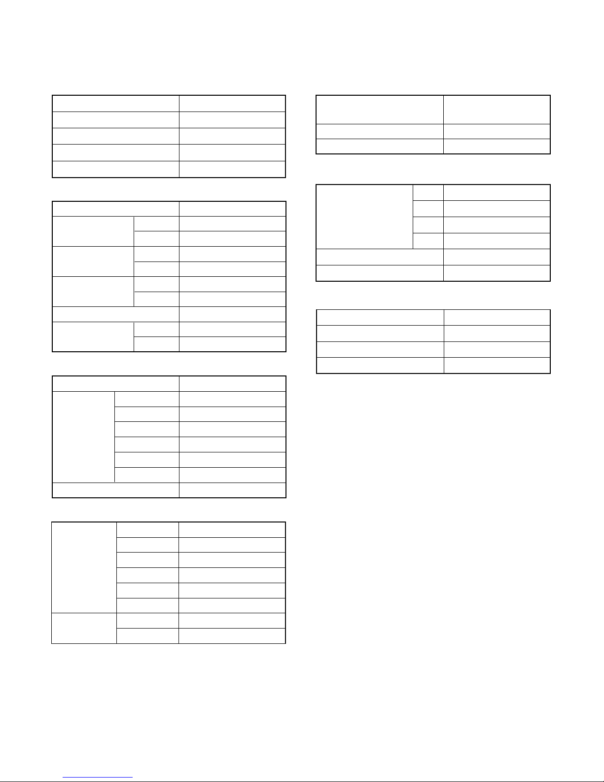
1 . SPECIFICATIONS
R410A
CEILING WALL type
INVERTER
HEATING CAPACITY
POWER SUPPLY
RUNNING
CURRENT
COOLING
HEATING
10.3 A
INPUT WATTS
COOLING
HEATING
2.35 kW
E.E.R.
COOLING
HEATING
COOLING
HEATING
3.62 kW/kW
MOISTURE REMOVAL
AIR CIRCULATION
HIGH
Cooling and heating inverter
AW *Z24LBC
AO*Z24LBT
7.1 kW
8.5 kW
TYPE
INDOOR UNIT
OUTDOOR UNIT
COOLING CAPACITY
230 V 50 Hz
9.7 A
2.21 kW
3.0 L/hr
3.21 kW/kW
ELECTRICAL DATA
POWER SOURCE 230 V
HIGH SPEED
1,500 r.p.m. / 1,700 r.p.m.
HIGH2 1,700 r.p.m. / 1,850 r.p.m.
INDOOR UNIT
( cool / heat )
MED SPEED
1,370 r.p.m. / 1,540 r.p.m.
SUPER QUIET
1,030 r.p.m. / 1,120 r.p.m.
QUIET
1,130 r.p.m. / 1,260 r.p.m.
LOW SPEED
1,250 r.p.m. / 1,390 r.p.m.
OUTDOOR UNIT ( cool / heat )
850 r.p.m. / 900 r.p.m.
FAN MOTOR
DIMENSIONS and WEIGHT
INDOOR UNIT
H x W x D
OUTDOOR UNIT
830 x 900 x 330 mm
250 x 899 x 298 mm
INDOOR UNIT Gross / Net
H x W x D
Gross / NetOUTDOOR UNIT 70 kg / 62 kg
17.5 kg / 14 kg
REFRIGERANT CHARGE (R410A)
FULL CHARGE
2,100 g
15 m
20 m
25 m
30 m
Pipe Length
2,200 g
1,900 g
2,000 g
ADDITIONAL CHARGE
20 g/m
MAX PIPE LENGTH
30 m
COMPRESSOR
TYPE
DISCRIMINATION
REFRIGERANT
R410A 1,900 g
5KD240XAD21
Hermetic type, DC Inverter,
Twin rotary
SPECIFICATIONS
HIGH SPEED
HIGH SPEED
880 m3/hr
980 m
3
/hr
47 dB / 47 dB
43 dB / 43 dB
40 dB / 40 dB
36 dB / 36 dB
32 dB / 32 dB
53 dB / 54 dB
HIGH2 49 dB / 49 dB
HIGH2 53 dB / 54 dB
INDOOR UNIT
( cool / heat )
MED SPEED
LOW SPEED
SUPER QUIET
QUIET
OUTDOOR UNIT
( cool / heat )
NOISE LEVEL
Note :
Noise was measured in accordance with JIS standards, Japan.
"HIGH2" means when ability measurement.
01-01

2 . DIMENSIONS
R410A
CEILING WALL type
INVERTER
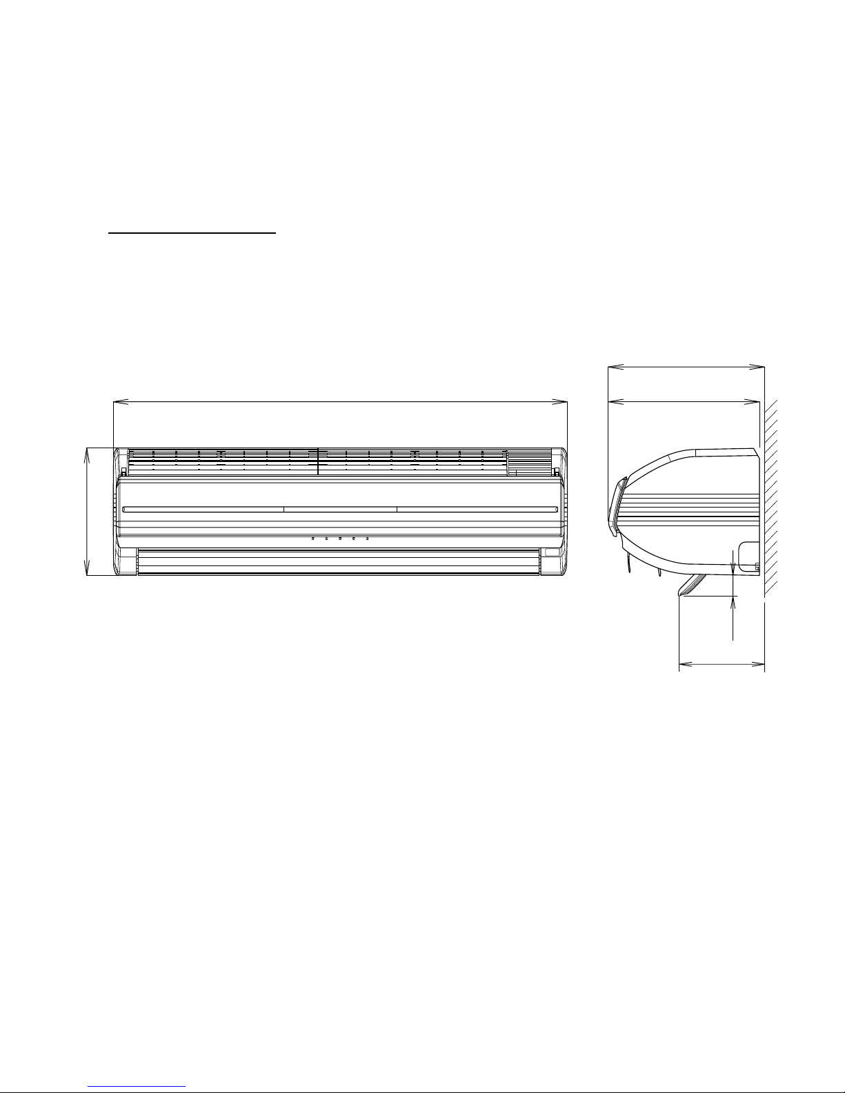
(Unit : mm)
DIMENSIONS
INDOOR UNIT
02-01
Models :
AW * Z24LBC
300
298
899
250
170
40
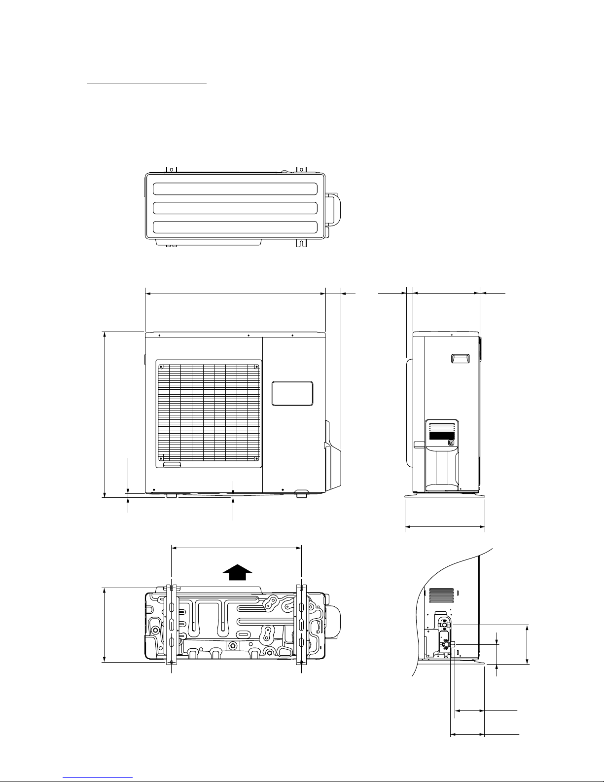
OUTDOOR UNIT
(unit : mm)
77900
830
21
9
400
33031 12
196
147
170
99
370
650
Air Flow
02-02
Models :
AO * Z24LBT

3 . REFRIGERANT SYSTEM DIAGRAM
R410A
CEILING WALL type
INVERTER
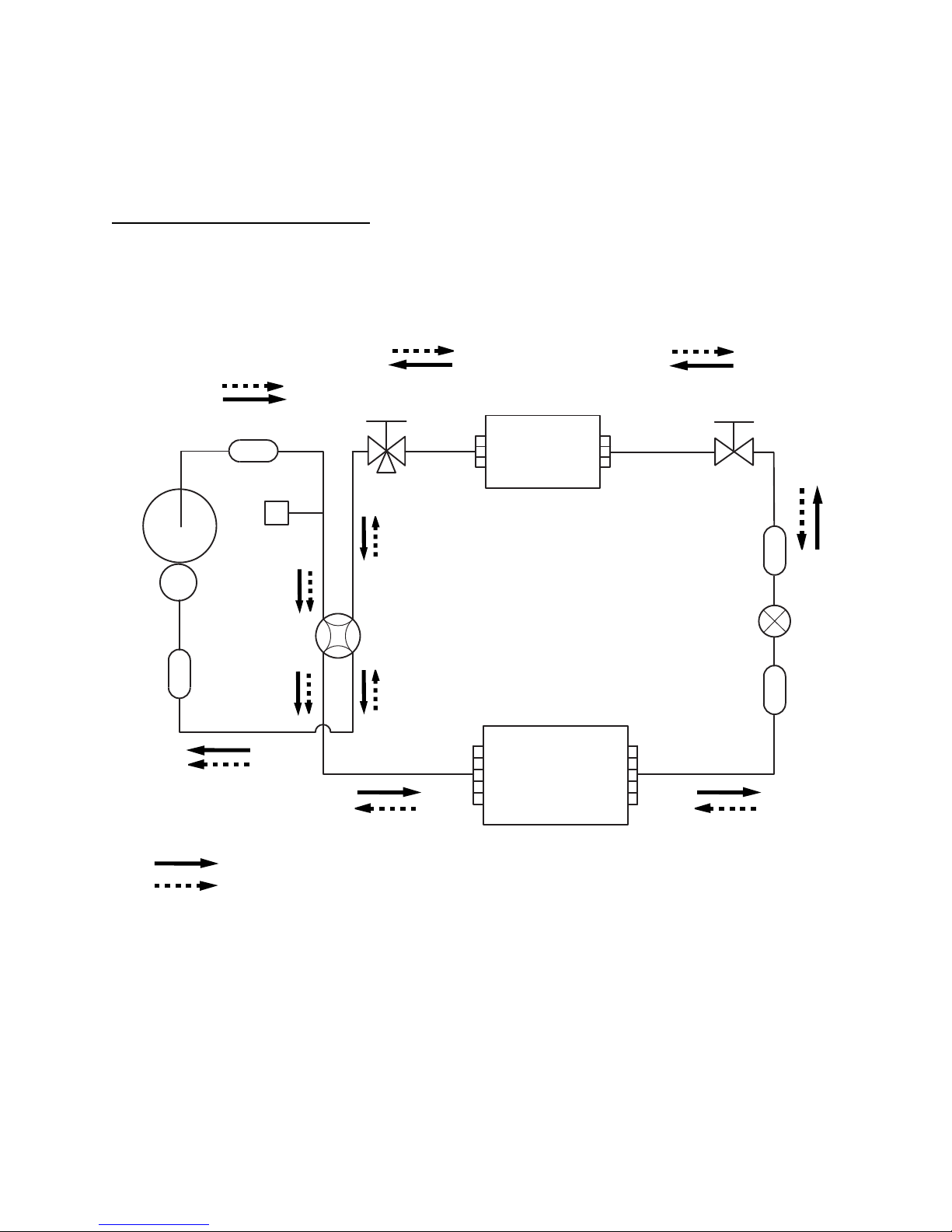
REFRIGERANT SYSTEM DIAGRAM
2-Way valve
(Small)
3-Way valve
(Large)
Strainer
Strainer
Muffler
Pressure
switch
4-Way valve
Expansion valve
Heat exchanger
( INDOOR )
Heat exchanger
( OUTDOOR )
Sub-accumulator
Compressor
Refrigerant pipe diameter
Liquid : 1/4" (6.35 mm)
Gas : 5/8" (15.88 mm)
Cooling
Heating
03-01
Models : AW * Z24LBC / AO * Z24LBT

4 . CIRCUIT DIAGRAM
R410A
CEILING WALL type
INVERTER
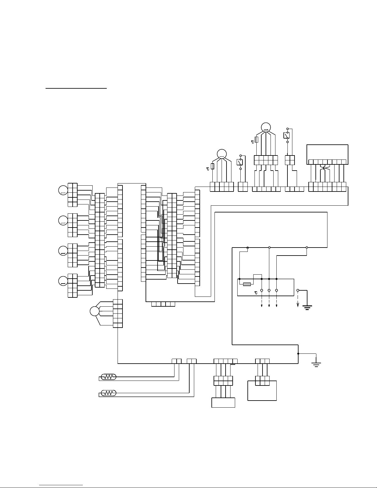
INDOOR UNIT
CIRCUIT DIAGRAM
04-01
WHITE
WHITE
WHITE
WHITE
WHITE
WHITE
WHITE
WHITE
WHITE
WHITE
WHITE
WHITE
WHITE
WHITE
WHITE
WHITE
RED
RED
RED
RED
RED
WHITE
WHITE
WHITE
WHITE
WHITE
WHITE
WHITE
WHITE
BROWN
ORANGE
YELLOW
GREEN
BLUE
PURPLE
GRAY
WHITE
BLACK
WHITE
WHITE
WHITE
WHITE
WHITE
WHITE
WHITE
WHITE
RED
WHITE
WHITE
WHITE
WHITE
WHITE
WHITE
WHITE
WHITE
RED
WHITE
WHITE
WHITE
WHITE
WHITE
WHITE
WHITE
WHITE
WHITE
RED
RED
WHITE
WHITE
WHITE
WHITE
WHITE
WHITE
WHITE
WHITE
WHITE
BLUE
YELLOW
WHITE
BLACK
RED
WHITE
WHITE
WHITE
WHITE
WHITE
WHITE
WHITE
WHITE
RED
RED
WHITE
RED
WHITE
WHITE
WHITE
WHITE
RED
WHITE
RED
WHITE
WHITE
BROWN
RED
ORANGE
YELLOW
BROWN
RED
ORANGE
YELLOW
WHITE
WHITE
WHITE
WHITE
WHITE
RED
RED
BLUE
WHITE
BLACK
RED
BLACK
BLACK
BLACK
BLACK
20
19
18
17
16
15
14
13
12
11
10
9
8
7
6
5
4
3
2
1
11
10
9
8
7
6
5
4
3
2
1
20
19
18
17
16
15
14
13
12
11
10
9
8
7
6
5
4
3
2
1
11
10
9
8
7
6
5
4
3
2
1
10
9
8
7
6
5
4
3
2
1
18
17
16
15
14
13
12
11
10
9
8
7
6
5
4
3
2
1
18
17
16
15
14
13
12
11
10
9
8
7
6
5
4
3
2
1
5
4
3
2
1
5
4
3
2
1
5
4
3
2
1
5
4
3
2
1
5
4
3
2
1
5
4
3
2
1
5
4
3
2
1
5
4
3
2
1
6
5
4
3
2
1
6
5
4
3
2
1
10
9
8
7
6
5
4
3
2
1
10
9
8
7
6
5
4
3
2
1
10
9
8
7
6
5
4
3
2
1
1234567
8
1234567
8
1234561234
1
2
1
212345
12345
12345
12345 12
12
12
345
678
12345
12345
1234
1234
123
12
3
123
12 12
CN205
TEST
CN12CN17
CN7
CN6
CN3
CN4
CN16
CN9
CN206
CN15
CN11
CN201
CN200
CN203
CN202 CN204
CN208
CN210
3
3
1
1
SW (LEFT)
SW (RIGHT)
THERMAL
FUSE 102
AIR FILTER (LEFT)
AIR FILTER (RIGHT)
THERMAL
FUSE 102
TM1
TM2
LOUVER U
LOUVER Z
LOUVER
(RIGHT-LEFT)
DIFFUSER
FAN MOTOR
CONNECTOR (WHITE)
CONNECTOR (WHITE)
CONNECTOR (RED)
CONNECTOR (RED)
ROOM TEMP. THERMISTOR
PIPE TEMP. THERMISTOR
RECEIVER PCB
UV-LED UNIT
W3
CONTROLLER PCB
F M
M
M
CONNECTOR PCB
INDICATOR PCB
M
M
M
M
TM4
WHITE
BLACK
RED
THERMAL
FUSE 102
TERMINAL
N
L
3
OUTDOOR UNIT
Models : AW * Z24LBC
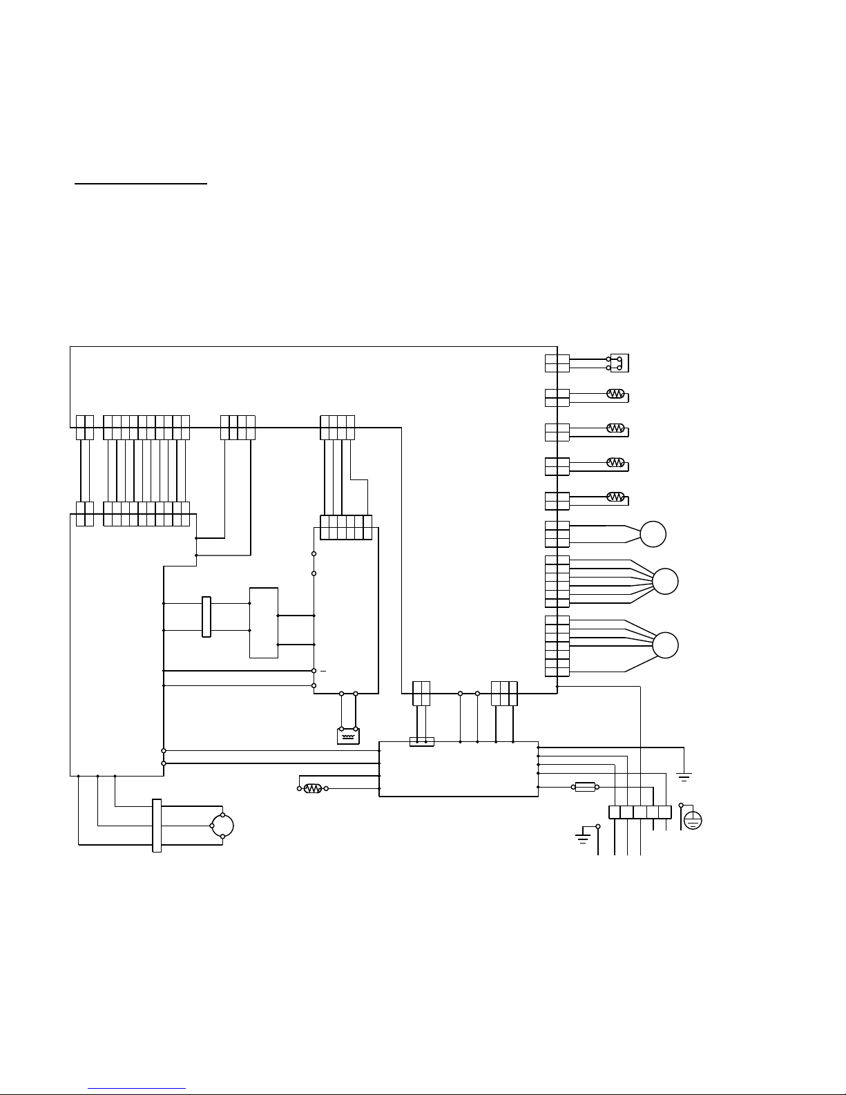
OUTDOOR UNIT
04-02
RED
RED
BROWN
BROWN
BLUE
BLUE
BLACK
BLACK
BROWN
BROWN
BLACK
BLACK
WHITE
YELLOW
ORANGE
BLUE
BROWN
RED
BROWN
YELLOW
WHITE
BLACK
RED
RED
BLACK
GREEN
BLACK
WHITE
WHITE
BLACK
PURPLE
WHITE
YELLOW
YELLOW
BLUE
BLUE
BLACK
RED
BROWN
ORANGE
BLACK BLACK
WHITE
WHITE
RED RED
ORANGE
ORANGE
BLACK
WHITE
BROWN
RED
BROWN
RED
ORANGE
YELLOW
GREEN
BLUE
PURPLE
GRAY
BLACK
WHITE
BROWN
RED
ORANGE
YELLOW
BLACK
BLACK
WHITE
GRAY
WHITE
WHITE
109
87654
321
109
87654
321
21
109
87654
321
109
87654
321
654
321
654
321
4
321
4
321
4
321
4
321
321
321
21
21
21
7
6
5
4
3
21
21
2
1
6
5
4
3
2
1
7
6
5
4
3
2
1
6
5
4
3
2
1
3
2
1
3
2
1
2
1
2
121
212
1
2
1
2
1
212
1
2
1
CN700
CN801
CN500
CN110CN1
CN400
CN200
CN11
CN60
CN61
CN62
CN64
CN90
CN40CN42
CN303 CN301
W306
W307
W302
W301
W17
W16
TM102
TM101
W303
W
W304
V
W305
U
W8
W7
W13
W12
L2 L1
+
P
N1
N2
I O
TM600
TM601
W4
R
C
S
CN100
12
W29
W28
W25
W26
W21 W20
W9
W17
W3
W18
W2
W1
W19
WHITE
WHITE
TERMINAL
FUSE 250V 25A
123LN
POWER SOURCE
TO INDOOR UNIT
FAN MOTOR
EXPANSION VALVE
4-WAY VALVE
F M
PMV
4WV
DISCHARGE TEMP. THERMISTOR
PIPE TEMP. THERMISTOR
OUTDOOR TEMP. THERMISTOR
COMPRESSOR TEMP. THERMISTOR
HIGH PRESSURE SWITCH
CHOKE COIL
POSISTOR
COMPRESSOR
C M
CONNECTOR
CONNECTOR
CAPACITOR PCB
ACTPM
I P M PCB
POWER SUPPLY PCB
CONTROLLER PCB
( MAIN PCB )
Models : AO * Z24LBT

5 . DESCRIPTION OF EACH
CONTROL OPERATION
R410A
CEILING WALL type
INVERTER
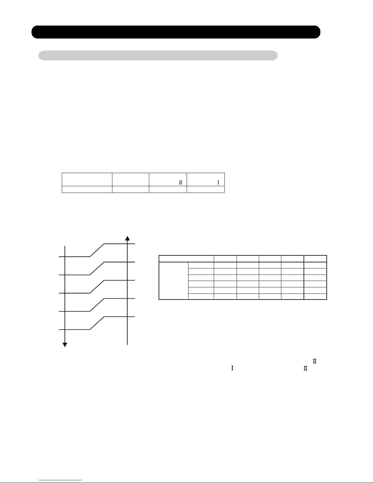
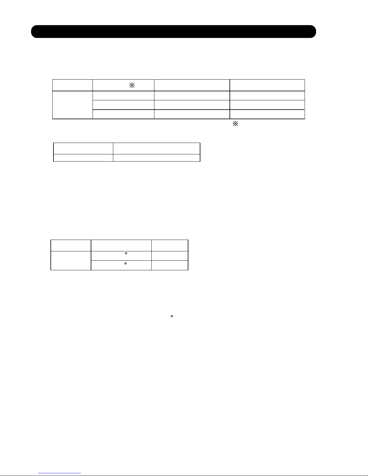
1. COOLING OPERATION
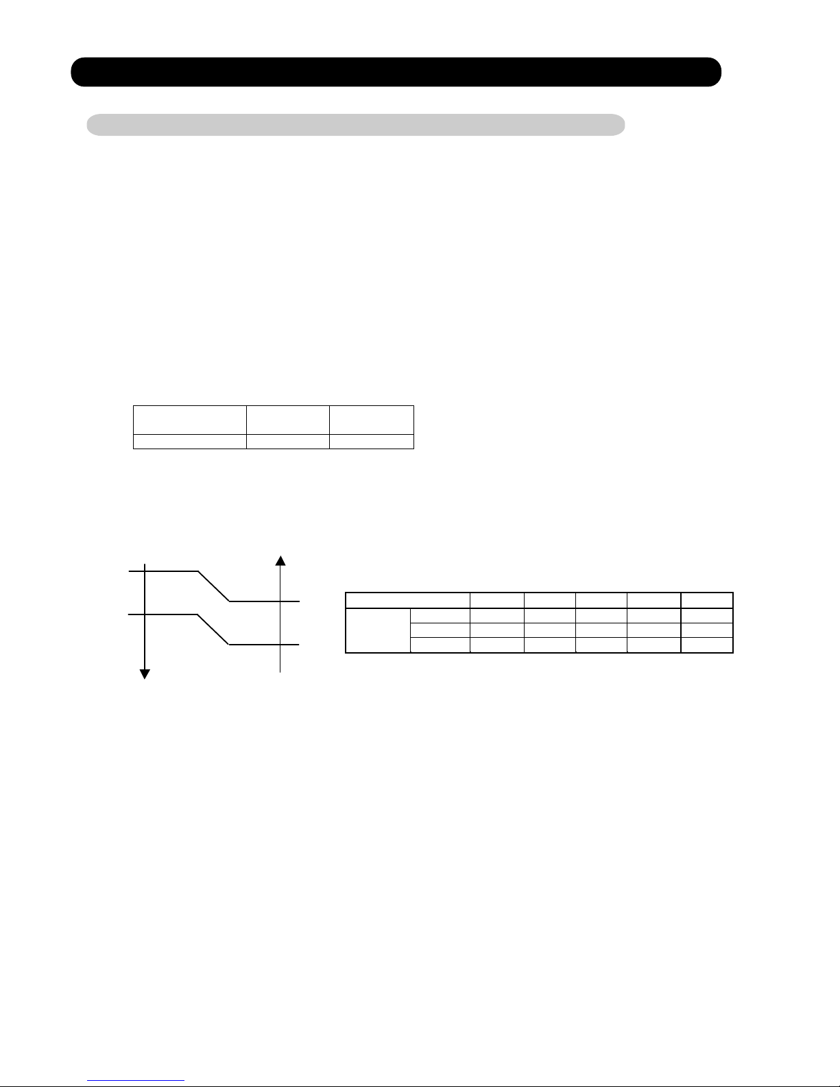
1-1 COOLING CAPACITY CONTROL
A sensor (room temperature thermistor) built in the indoor unit body will usually perceive
difference or variation between a set temperature and present room temperature, and
controls the operation frequency of the compressor.
* If the room temperature is 2°C higher than a set temperature, the compressor operation
frequency will attain to maximum performance.
minimum
frequency
maximum
frequency
maximum
frequency
AW * Z24LBC 21Hz 47Hz 63Hz
Outside air Outside air
temperature temperature
36°C
A zone
34°C
32°C
B zone
30°C
21°C
C zone
19°C
D zone
Hi Me Lo Quiet
A zone 63Hz 43Hz 37Hz 27Hz
B zone 63Hz 43Hz 37Hz 27Hz
C zone 57Hz 39Hz 33Hz 23Hz
24LBC
D zone 39Hz 31Hz 27Hz 21Hz
E zone 39Hz 31Hz 27Hz 21Hz
F zone 39Hz 31Hz 27Hz 21Hz
S-Quiet
25Hz
25Hz
21Hz
21Hz
21Hz
21Hz
( Table 1 : Compressor Frequency Range )
When the compressor operates for 30 minutes continuously at over the maximum frequency ,
the maximum frequency is changed from Maximum Frequency to Maximum Frequency .
The room temperature is controlled 1°C lower than the setting temperature for 40 minutes
after starting the operation.
After 40 minutes, it is controlled based on the normal setting temperature.
05-01
E zone
F zone
10°C
0°C
12°C
2°C
* When the room temperature is between +2°C to -2.5°C of the setting temperature,
the compressor frequency is controlled within the range shown in Table1.
However, the maximum frequency is limited in the range shown in Figure 1 based on the
fan speed mode and the outdoor temperature.
* If the room temperature is 2.5°C lower than a set temperature, the compressor will be
stopped.
( Fig.1 : Limit of Maximum Frequency based on Outdoor Temperature )
2. HEATING OPERATION
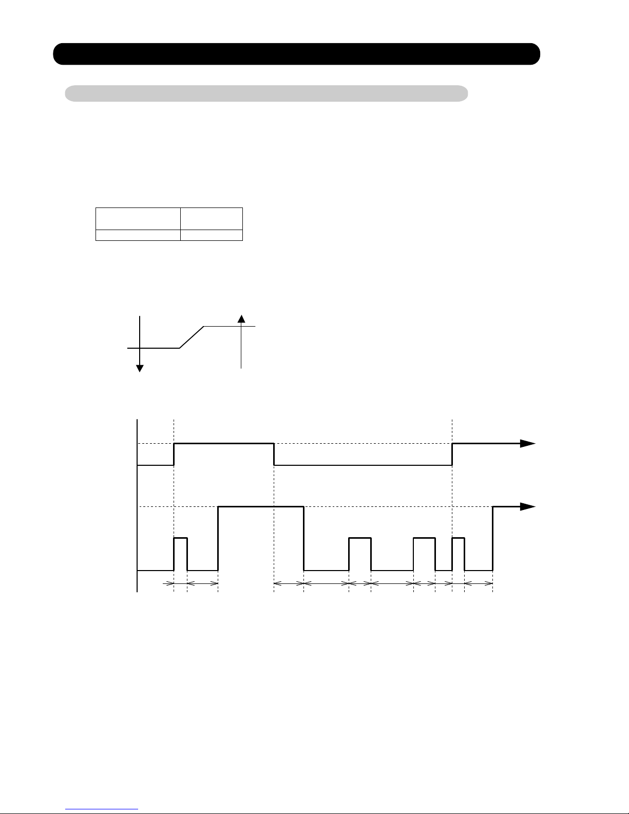
2-1 HEATING CAPACITY CONTROL
A sensor (room temperature thermistor) built in the indoor unit body will usually perceive
difference or variation between a set temperature and present room temperature, and
controls the operation frequency of the compressor.
* If the room temperature is lower by 3°C than a set temperature, the compressor operation
frequency will attain to maximum performance.
* If the room temperature is higher 2.5°C than a set temperatire, the compressor will be
stopped.
minimum
frequency
maximum
frequency
AW * Z24LBC 21Hz 87Hz
Outside air Outside air
temperature temperature
19°C
C zone
17°C
14°C
B zone
12°C
A zone
Hi Me Lo Quiet
A zone 87Hz 63Hz 51Hz 49Hz
B zone 87Hz 63Hz 51Hz 47Hz
24LBC
C zone 87Hz 63Hz 51Hz 43Hz
S-Quiet
47Hz
43Hz
39Hz
* When the room temperature is between +2°C to -3°C of the setting temperature,
the compressor frequency is controlled within the range shown in Table2.
However, the maximum frequency is limited in the range shown in Figure 2 based on the
fan speed mode and the outdoor temperature.
( Table 2 : Compressor Frequency Range )
( Fig.2 : Limit of Maximum Frequency based on Outdoor Temperature )
* The room temperature is controlled 2°C higher than the setting temperature for 60 minutes
after starting the operation.
After 60 minutes, it is controlled based on the normal setting temperature.
05-02
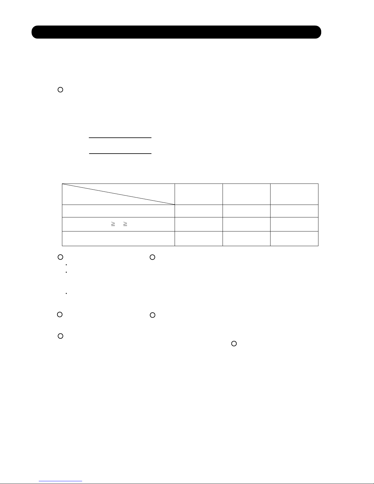
3. DRY OPERATION
3-1 INDOOR UNIT CONTROL
The compressor rotation frequency shall change according to the temperature, set temperature,
and room temperature variation which the room temperature sensor of the indoor unit body has
detected as shown in the Table 3. However, after the compressor is driven, the indoor unit shall
run at operation frequency of 58Hz, for a minute.
Operating
frequency
AW * Z24LBC 23Hz
room room
temperature temperature
compressor ON
Ts+1.5°C
Ts+0.5°C
compressor OFF
Compressor
ON
OFF
Indoor fan
Dry air flow
S-Lo
OFF
( Table 3 : Compressor frequency )
( Fig.3 : Compressor Control based on Room Temperature )
( Fig.4 : Indoor Fan Control )
05-03
10 30 60 180 60 180 60 10 30
(SEC)
4. AUTO CHANGEOVER OPERATION
When the air conditioner is set to the AUTO mode by remote control, operation starts in the optimum
mode from among the HEATING, COOLING, DRY and MONITORING modes. During operation, the
optimum mode is automatically switched in accordance with temperature changes. The temperature
can be set between 18°C and 30°C in 1°C steps.
.When operation starts, only the indoor and outdoor fans are operated for 1 minute. After 1 minute,
the room temperature and outside air temperature are sensed and the operation mode is
selected in accordance with the table below.
C zone
32°C
B zone
-10°C
A zone
( Table.4 Operation mode selection table)
Outside air temperature (To)
Room temperature (Tb)
A zone B zone C zone
Tb > Ts+2°C
Tb < Ts - 2°C
Monitoring
Cooling
(automatic dry)
Cooling
(automatic dry)
Ts+2°C Tb Ts - 2°C
Monitoring Monitoring Monitoring
Heating Heating Monitoring
.When COOING was selected at , the air conditioner operates as follow:
The same operation as COOLING OPERATION of item 1 above is performed.
When the room temperature has remained at (set temperature -1°C) for 8 minutes, operation is
automatically switched to DRY and the same operation as DRY OPERATION of item 3 above
is performed.
If the room temperature reaches (set temperature +2°C during DRY operation, operation returns to
COOLING operation.
.When HEATING was selected at , the same operation as HEATING OPERATION of item 2
above is performed.
When the compressor was stopped for 6 consecutive minutes by the temperature control function
after the COOLING or HEATING operation mode was selected at above, operation is switched
to MONITORING and the operation mode is selected again.
1
1
2
3
1
4
1
( Fig.5 : Outside air temperature zone selection )
05-04

5. INDOOR FAN CONTROL
(1).Fan speed
( Table 5 : Indoor Fan Speed )
Except S-Quiet
(2).FAN OPERATION
The airflow can be switched in 5 steps such as AUTO, QUIET, LOW, MED, HIGH, while the indoor
fan only runs.
When Fan mode is set at (Auto), it operates on (MED) Fan Speed.
AW * Z24LBC
Operation mode Air flow mode Speed (rpm)
Hi 1,700
Me+ 1,610
Me 1,510
Lo 1,390
Quiet 1,260
S-Quiet
S-Quiet
S-Quiet
1,120
Cool air
prevention
850
Heating
S-Lo 480
Hi 1,500
Me 1,370
Lo 1,250
Cooling
Fan
Quiet
1,030
1,130
Dry
1,030
05-05
1,130
(3).COOLING OPERATION
Switch the airflow [AUTO], and the (Fig.6)
indoor fan motor will run according
airflow change - over ( Cooling:AUTO )
to a room temperature, as shown in
When the room
Figure 6.
temperature rises
On the other hand, if switched in
[HIGH]
[QUIET], the indoor motor
+2.5°C
will run at a constant airflow of [COOL]
operation modes QUIET, LOW, MED,
HIGH, as shown in Table 5.
+1.5°C
+1°C
LOW mode
When the room
temperature lowers
(Room temperature) D (Setting temperature)
(4).DRY OPERATION
(5).HEATING OPERATION
Switch the airflow [AUTO], and the (Fig.7)
indoor fan motor will run according
airflow change - over ( Heating:AUTO)
to a room temperature, as shown in
When the room
Figure 7. temperature rises
On the other hand, if switched
LOW mode
[HIGH]
[QUIET], the indoor motor -1°C
will run at a constant airflow of [HEAT]
-1.5°C
operation modes QUIET, LOW, MED,
HIGH, as shown in Table 5.
-2°C
-2.5°C
MED + mode
When the room
temperature lowers
(Room temperature) D (Setting temperature)
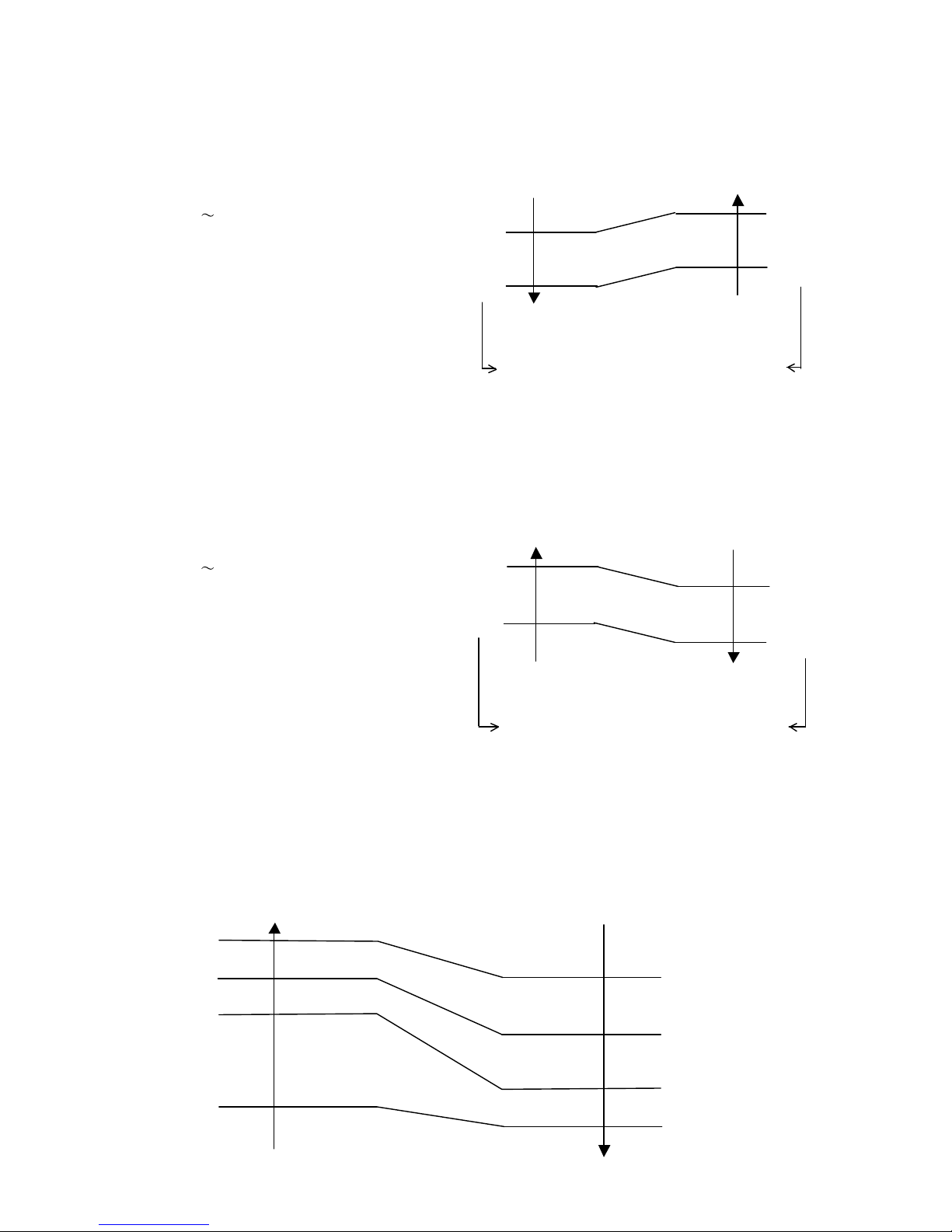
(6).COOL AIR PREVENTION CONTROL (Heating mode)
Indoor heat exchanger Indoor heat exchanger
temperature temperature
47°C
Hi
40°C
Me+
37°C
Lo
Cool air prevention
30°C
S-Lo
Refer to the table 4.
Durring the dry mode operation, the fan speed
setting can not be changed.
The maximum value of the indoor fan speed is set as shown in Figure 8, based on the detected
temperature by the indoor heat exchanger sensor on heating mode.
(Fig.8 : Cool Air Prevention Control)
05-06
40°C
28°C
32°C
34°C
HIGH mode
MED mode
+2°C
MED mode
6. OUTDOOR FAN CONTROL
(1). Fan speed
Zone
AW * Z24LBC
Heating
AW * Z24LBC
900/780/700/550/450rpm
Table 6 : Fan speed (Cooling, Dry)
Table 7 : Fan speed (Heating)
The outdoor fan speed is changed in the range of the speed shown in the above table,
based on the frequency of the compressor.
(When the compressor frequency increases, the outdoor fan speed is also changed to
higher speed. If the compressor frequency decreases, the outdoor fan speed is changed
to the lower speed as well.)
After starting up the outdoor fan, it operates with the following speed for initial 20 seconds.
*
Table 8 : Fan speed when starting up Outdoor fan
*
After operating the defrost control function on heating mode, its speed becomes 1,000rpm
regardless of the compressor frequency.
However, it returns to the normal speed control when the defrosting operation does not function
for 240 minutes after releasing the defrost operation or when the outdoor temperature sensor
detection value becomes higher than 5 C.
05-07
A to D
Cooling
850/780/700/500rpm
500/250/200rpm
320/250/200rpm
Dry
550/450rpm
500/250/200rpm
320/250/200rpm
Outdoor temperature
AW * Z24LBC
Speed
500rpm
200rpm
Over than 12 C
Less than 12 C
E
F
Refer to Fig.1

7. LOUVER CONTROL
05-08
(1). LOUVER CONTROL
Each time the button is pressed, the air direction range will change as follow:
Cooling / Dry mode
Heating mode
Fan mode
Use the air direction adjustments within the ranges shown above.
The vertical airflow direction is set automatically as shown, in accordance with the type of operation
selected.
Cooling / Dry mode
Horizontal flow
Heating mode
Downward flow
When the temperature of the air being blown out is low at the start of heating operation or during
defrosting, the airflow direction temporarily becomes
to prevent cold air being blown onto the body.
During Monitor operation in AUTO CHANGEOVER mode, the airflow direction automatically
becomes
.
(Function Range)
(Fig 9: Air Direction Range)
(Operation Range)
When the indoor control interface device receives a control signal light from the remote control,
it will actuate, the step motor according to the control signal, and set the louver to each position.
In addition, if the air conditioner is stopped, vertical louver will be closed automatically.
Vertical Air Direction Adjustment
6
Each time the button is pressed, the air direction range will change as follow:
(Function Range)
Horizontal Air Direction Adjustment
7
1
8
778
8
5
6
Cooling mode / Dry mode / Fan mode( )
Heating mode / Fan mode(
)
(2). SWING OPERATION
When the swing signal is received from the remote controller, the vertical louver starts to swing.
(Swinging Range)
When the indoor fan is at S-Lo or Stop mode, the swinging operation is interrupted
and it stops at either right end or left end.
14
1
4
5
8
88
To select Vertical Airflow Swing Operation
To select Horizontal Airflow Swing Operation
When the swing signal is received from the remote controller, the horizontal louver starts to swing.
All mode :
(Swinging Range)
3
1
When the indoor fan is S-Lo or Stop mode, the swinging operation is interrupted
and it stops at either upper end or bottom end.
To select Vertical and Horizontal Airflow Swing Operation
When the horizontal swing signal is input from remote control, the combination of the vertical
and horizontal swing operation is performed.
8. COMPRESSOR CONTROL
(1). OPEARTION FREQUENCY RANGE
The operation frequency of the compressor is different based on the operation mode as
shown in the table 9.
Cooling Heating
Min Max Min Max
Dry
AW * Z24LBC 21Hz 75Hz 21Hz 87Hz 23Hz
AW * Z24LBC 40Hz 59Hz
(Table 9 : Compressor Operation Frequency Range)
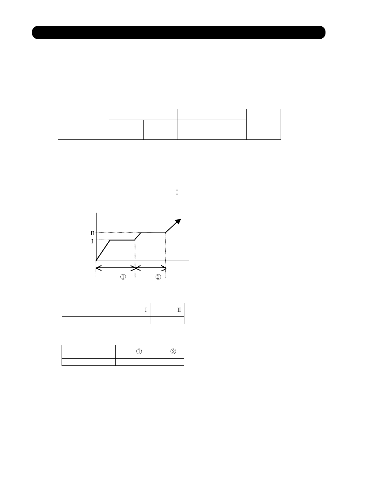
(2). OPEARTION FREQUENCY CONTROL AT START UP
The compressor frequency soon after the start-up is controlled as shown in the figure 10.
(Fig.10 : Compressor Control at Start-up )
Time
Time
(Frequency)
(Time)
Frequency
Frequency
Time Time
Frequency
Frequency
05-09
AW * Z24LBC
60sec 40sec
AW * Z24LBC
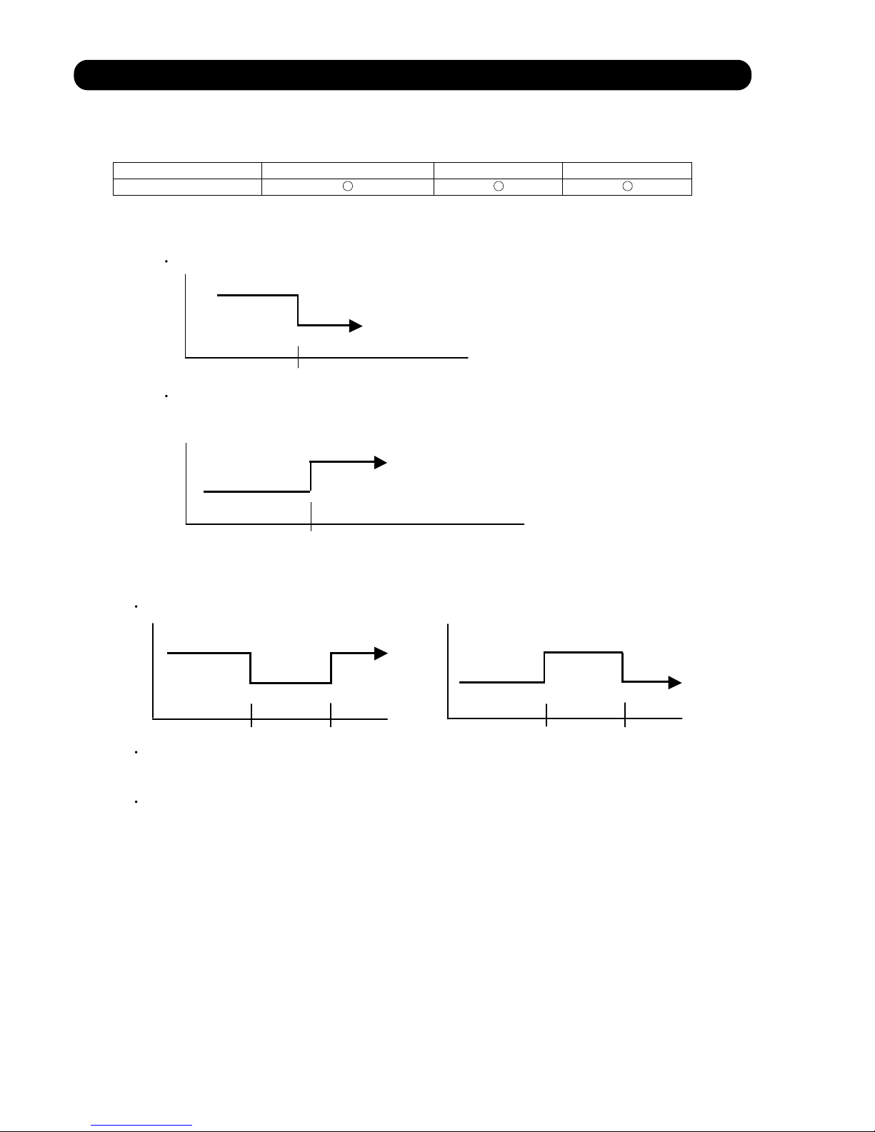
9. TIMER OPEARTION CONTROL
(1). OPEARTION FREQUENCY RANGE
The table 9 shows the available timer setting based on the product model.
ON TIMER / OFF TIMER PROGRAM TIMER SLEEP TIMER
AW * Z24LBC
OFF timer : When the clock reaches the set time, the air conditioner will be turned off.
Operation mode
Stop mode
Set time of timer
ON timer : When the clock reaches the set time, the air conditioner will be turned on.
Operation mode
Stop mode
Set time of timer
The program timer allows the OFF timer and ON timer to be used in combination one time.
Operation mode
Operation will start from the timer setting (either OFF timer or ON timer) whichever is closest
to the clock's current timer setting. The order of operations is indicated by the arrow in the remote
control unit's display.
SLEEP timer operation cannot be combined with ON timer operation.
(Table 9 : Timer Setting)
(2). PROGRAM TIMER
Stop mode
Stop mode
Stop mode
Operation mode
Operation mode
Set time
Set time Set time Set time
05-10
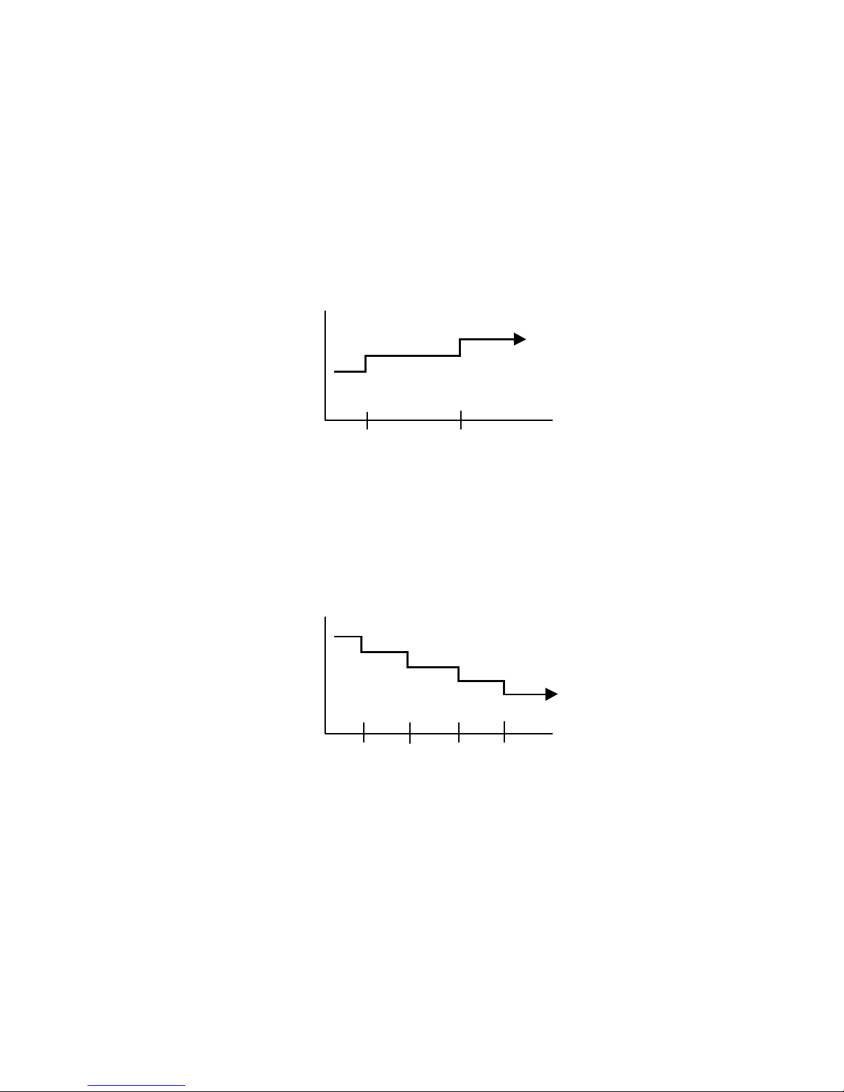
(3). SLEEP TIMER
If the sleep is set, the room temperature is monitored and the operation is stopped automatically.
If the operation mode or the set temperature is change after the sleep timer is set, the operation is
continued according to the changed setting of the sleep timer from that time ON.
Set temperature rises
( Ts : Set temperature )
Stop of operation
Set temperature lowers
( Ts : Set temperature )
Ts
Stop of operation
In the cooling operation mode
When the sleep timer is set, the setting temperature is increased 1°C.
It increases the setting temperature another 1°C after 1 hour.
After that, the setting temperature is not changed and the operation is stopped at the time
of timer setting.
Ts
+1°C
+2°C
Set
60min
In the heating operation mode
When the sleep timer is set, the setting temperature is decreased 1°C.
It decreases the setting temperature another 1°C every 30 minutes.
Upon lowering 4°C, the setting temperature is not changed and the operation stops at
the time of timer setting.
-4°C
-3°C
-2°C
-1°C
Set
30min
30min
30min
05-11

10. ELECTRONIC EXPANSION VALVE CONTROL
The most proper opening of the electronic expansion valve is calculated and controlled under the
present operating condition based on the following values.
The compressor frequency, the temperatures detected by the discharge temperature sensor, the
indoor heat exchanger sensor, the outdoor heat exchanger sensor, and the outdoor temperature
sensor.
11. TEST OPERATION CONTROL
Under the condition where the air conditioner runs, press the test operation button of the remote
control, and the test operation control mode will appear. During test running, the operation lamp
and timer lamp of the air conditioner body twinkle simultaneously. Set the test operation mode,
and the compressor will continue to run regardless of whether the room temperature sensor detects.
The compressor won't enter operation status for 3 minutes after the compressor is stopped,
even if any operation is given.
At the time when the air conditioner is switched from the cooling mode to heating mode, the
compressor is stopped, and the four-way valve is switched in 3 minutes later after the compressor
stopped.
When the power was interrupted by a power failure, etc. during operation, the operation contents
at that time are memorized and when power is recovered, operation is automatically started with
the memorized operation contents.
When the power is interrupted and recovered during timer operation, since the timer operation time
is shifted by the time the power was interrupted, an alarm is given by blinking (7 sec ON/2 sec OFF)
the indoor unit body timer lamp.
[Operation contents memorized when the power is interrupted]
Operation mode
Set temperature
Set air flow
Timer mode and timer time
Set air flow Direction
Swing
The test operation mode is released if 60 minutes have passed after setting up the test operation.
12. PREVENT TO RESTART FOR 3 MINUTES ( 3 MINUTES ST )
13. FOUR-WAY VALVE EXTENSION SELECT
14. AUTO RESTART
05-12
AW * Z24LBC
Pulse range
40 480 pulse
(1) Pulse range of EEV
(2) The EEV is set up at 480 pulses when the compressor is stopped.
(3) Intialization (Input of 528 pulses toward closing direction) is operated under the
following condition.
* When the power is turned on.
* 3 hours has passed since the last initialization, and 3 minutes has passed after
the compressor stop.
(If 12 hours has passed since the last initialization, the compressor is compulsorily
stopped.)
15. MANUAL AUTO OPERATION (Indoor unit body operation)
If MANUAL AUTO Button is set (Push a MANUAL AUTO button for 3~10 seconds), the operation
If the remote control is lost or battery power dissipated, this function will work without the remote
control.
is controlled as shown in Table 10.
OPERATION MODE Auto changeover
FAN CONT. MODE Auto
TIMER MODE Continuous
SETTING TEMP. 24°C
SETTING LOUVER Standard
SWING OFF
When the outdoor heat exchanger temperature is lower than temperature and the heating operation has
been stopped for 30 minutes, power is applied to the compressor and the compressor is heated.
(By heating the compressor, warm air is quickly discharged when operation is started.)
When operation was started, and when the outdoor temperature rises to temperature or greater, preheating
is ended.
Filter Clean is operated after a coil dry operation end.
FIlter Clean function performs disinfection and deodorization of a filter with UV lamp during filter
movement.
Unit is stopped after Filter Clean operation.
AW * Z24LBC
AW * Z24LBC
1100rpm 29Hz
(Table 10)
(No timer setting available)
17. COMPRESSOR PREHEATING
(Table 11 : Preheating Operation / Release Temperature)
Temperature
Temperature
5°C
7°C
18. COIL DRY AND CLEAN OPERATION CONTROL
The coil-dry operation functions by pressing COIL DRY button on the remote controller.
The coil-dry operation is consisted of 3 cycles of [Fan operation 3 minutes / Heating operation
2 minutes], and Fan operates for 3 minutes at last before ending the air conditioner operation.
(It takes 18 minutes to complete the coil-dry operation.)
(Table 12 : COIL-DRY Operating Functions)
Indoor Fan Speed
Compressor
Frequency
Louver
Position
Main Unit
Indication
COIL-DRY indication : ON
Other indication : OFF
05-13
Forced cooling operation
Cooling
16. FORCED COOLING OPERATION
Forced cooling operation is started when pressing MANUAL AUTO button for 10 seconds or more.
During the forced cooling operation, it operates regardless of room temperature sensor.
Operation LED and timer LED blink during the forced cooling operation. They blink for 1 second ON
and 1 second OFF on both operation LED and timer LED (same as test operation).
Forced cooling operation is released after 60 minutes of starting operation.
The FORCED COOLING OPERATION will start as shown in Table10.
COIL DRY OPERATION CONTROL
Hi
Horizontal
OFF
Room Temp is not controlled
Manual auto operation
-
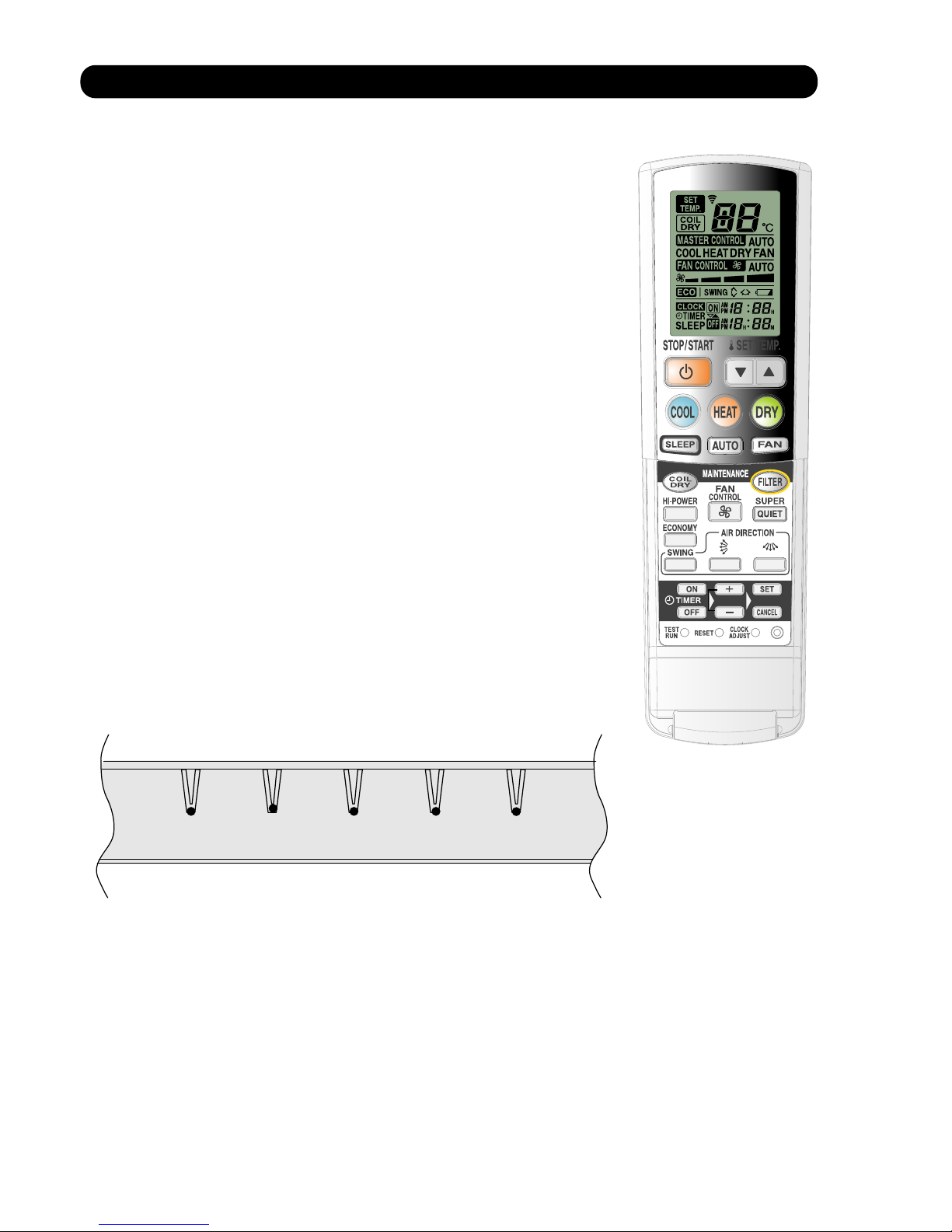
19. UV FILTER CLEANING CONTROL
1. SETTING METHOD
(1) Manual filter cleaning function
- Press [FILTER] button on remote controller to start filter cleaning.
(2) Automatic cleaning function
- Filter maintenance interval can be set at either 50 hours or 100 hours
with the remote controller ([SET TIME] button is kept pressed - refer to
the operation manual).
- When the accumulated operating time reached to the set up interval
time, the filter cleaning function automatically starts at the stop mode.
2. MAIN UNIT INDICATION
* Type of [MAINTENANCE SIGN] lamp (Red) indications on main unit.
- During the filter cleaning function
[MAINTENANCE SIGN] lamp (Red) is ON.
(It lights up only when the filter is functioning. Upon filter
function is completed, it goes off.)
- When the filter cleaning function is abnormal
[MAINTENANCE SIGN] lamp (Red) blinks (1 sec. ON / 1 sec. OFF)
- Notification of Dust box maintenance
[MAINTENANCE SIGN] lamp (Red) will light up.
It notifies the timing of Dust box maintenance. It lights up after 2,000
or 4,000 hours of operation by setting up with the auto cleaning
function time.
The red lamp will keep lighting until resetting the accumulated time,
regardless of air conditioner's operating mode.
3. REMOTE CONTROLLER CONDITION
The LCD indication does not change with [FILTER] button.
4. LIMIT SWITCH CONDITION FOR THE FILTER LOCATION DETECTION.
- Limit switch ON - On filter function, the filter is stopped on the way.
- Limit switch OFF - The filter is correctly installed, or The filter is not installed.
05-14
MAINTENANCE SIGN
TIMER OPERATION HI-POWER
SUPER QUIET

5. OPERATING FUNCTION
- UV filter cleaning function
UV LED is turned on during the filter cleaning operation to remove bacteria or to deodorize.
< Condition to light up UV-LED >
UV-LED is lighted up after 5 seconds of starting the filter cleaning operation.
If error is occurred during the filter operation, it is turned off.
6. PROTECTING FUNCTIONS
(1) Automatic filter retracting function
Under following conditions, the filter moves toward retracting direction until the limit switch
turns OFF.
- The limit switch is kept ON for 2 seconds when the power is turned on.
- The limit switch turns ON from OFF and it is kept ON for 2 seconds when the air conditioner
is in operating or stop mode.
> If the air conditioner is in operating mode, it does not stop the operation and functions the
filter.
(2) Filter mounting error protection
(a) Filter come out mounting error
(b) Filter retract mounting error
If above error occurs, it is memorized in EEPROM (Error history).
Error is indicated with blinking [MAINTENANCE SIGN] lamp (Red) for 1 sec. ON / 1 sec. OFF.
(3) Filter cleaning forced stop function when Dust box maintenance notification is in operation.
* When [MAINTENANCE SIGN] LED (Red) is ON, following functions do not work until reset
button will be pressed.
- Auto cleaning / Manual filter cleaning function
- Filter auto retract function
- Forced filter cleaning function, Off timer operating time auto cleaning.
* This protecting function can be released by pressing [MAINTENANCE/MANUAL AUTO]
button.
(4) Filter cleaning stepping motor temperature rise protection
Filter cleaning can be operated continuously up to 3 times.
(If it is operated 3 times continuously, it stops filter cleaning function for 3 minutes.)
(5) Forced filter cleaning protection for the continuous operation
When the operation time of air conditioner reaches to 200 hours, the operation is temporarily
stopped, and the filter cleaning is performed. Upon completion of the filter cleaning, it resumes
operation.
(6) Auto cleaning function protection for OFF Timer operating time
If the filter cleaning does not operate after 100 hours of air conditioner operating time and it is
reached to 150 hours, the filter cleaning function starts to operate at the time of stopping
operation by OFF Timer time up
05-15
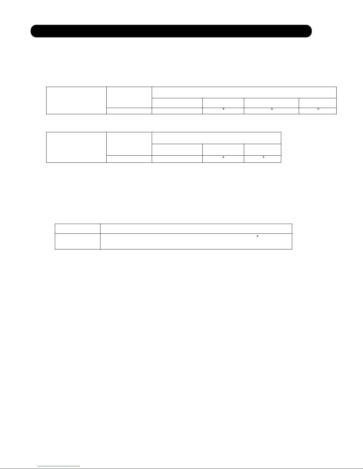
20. DEFROST OPERATION CONTROL
(1). CONDITION OF STARTING THE DEFROST OPERATION
The defrost operation starts when the outdoor heat exchanger temperature sensor detects
the temperature lower than the values shown in Table 15.
(Table 15 : Condition of starting Defrost Operation)
AW * Z24LBC
AW * Z24LBC
AW * Z24LBC
1 time defrosting
after starting
operation
ST
Defrosting after 2
time upon starting
operation
ND
Compressor operating time
Less than 17 minutes 17 to 60 minutes
60 minutes to 4 hours
After 4 hours
Does not operate
- 9 C
- 5 C
- 3 C
Less than 35 minutes
35 minutes to
4 hours
Does not operate
Compressor operating time
After 4 hours
- 3 C
- 6 C
(2). CONDITION OF THE DEFROST OPERATION COMPLETION
Defrost operation is released when the conditions become as shown in Table 16.
(Table 16 : Defrost Release Condition)
Release Condition
Outdoor heat exchanger temperature sensor value is higher than 13 C or
Compressor operation time has passed 15 minutes.
05-16
 Loading...