

Page 1
1. CEILING WALL TYPE :
AWZ14LBC
AWZ18LBC
AWZ24LBC
INDOOR UNIT
D2D_AW001E/02
2009.10.01
R410A
Page 2

- (01 - 01) -
CEILING WALL TYPE
AW
Z14-24 LB
CEILING WALL TYPE
AW
Z14-24 LB
FEATURE1.
AOZ14LBC
AOZ18LBC
AOZ24LBT
MODEL :
■
AWZ14LBC
AWZ18LBC
AWZ24LBC
FEATURES
■
Energy saving CLASS A cleared
●
with a margin to spare
Automatic lter cleaner
●
*1
Entire lter is cleaned automatically in approx. 2 minutes
Since the lter is cleaned automatically, energy saving capability is displayed without regard to the load on the air conditioner.
Bacteria eliminating countermeasure
●
Antibacterial dust box
Removes dirt and dust by double brushes. Dust collection is
approx. twice that in the past. (our company comparison)
Maintenance: Only throwing into a trash bin once every 2 years
a
c
d
e
b
a
Dirt and dust are bacteria-eliminated by photocatalytic lter*
* Displays double the effect of a conventional optical medium and retains its property for
a long time to suck in and remove approx. 99.99% of cigarette odors and bacteria, etc.
b
Drives away bacteria and refreshes the air
by UV (ultraviolet rays) illumination
Our unique technology that achieved
●
top energy efciency in the industry
c
Energy saving by automatic lter cleaning function
*1
This function allows an energy saving of more than 25% a year and maintains
a smooth air ow by preventing the lters from being clogged with dust.
CAE analysis
d
Computer-designed fan provides a larger
airow than conventional models
New air trunk, which provides a smooth airow,
and axial gap fan motor increase the max. airow
by 10% over that of conventional models.
CAE:Co mputer ai ded engineeri ng
e
Axial gap fan motor enables nonconventional
high power and high efciency*2
Axial gap method
Rotor plates are installed above and below electromagnets.
Features (Compared to conventional models)
Compact size with 1.5 more power output Self-driven method increases
rotating ef ciency by 10%. Our electromagnetic eld simulation technology
enables low vibration and low noise.
Thin copper
wire reduced
electric
resistance.
Area, which confronts
magnetic attraction is
very wide and generates
high power.
Rotor plate
Rotor plate
Electromagnet
Thin copper wire
Area, which confronts
magnetic attraction,
is very narrow.
Electromagnet
Rotor plate
Conventional motor
Rotor is bounded by electromagnet.
New model
*1: Announce d September 9, 200 2. In roo m air conditioner for the h ome
(Our com pany's investigation)
*2: Announced Decembe r 13, 2004. As fan mot or for air c onditioner (Ou r
company's investigati on)
Page 3
- (01 - 02) -
CEILING WALL TYPE
AW
Z14-24 LB
CEILING WALL TYPE
AW
Z14-24 LB
ALL DC
●
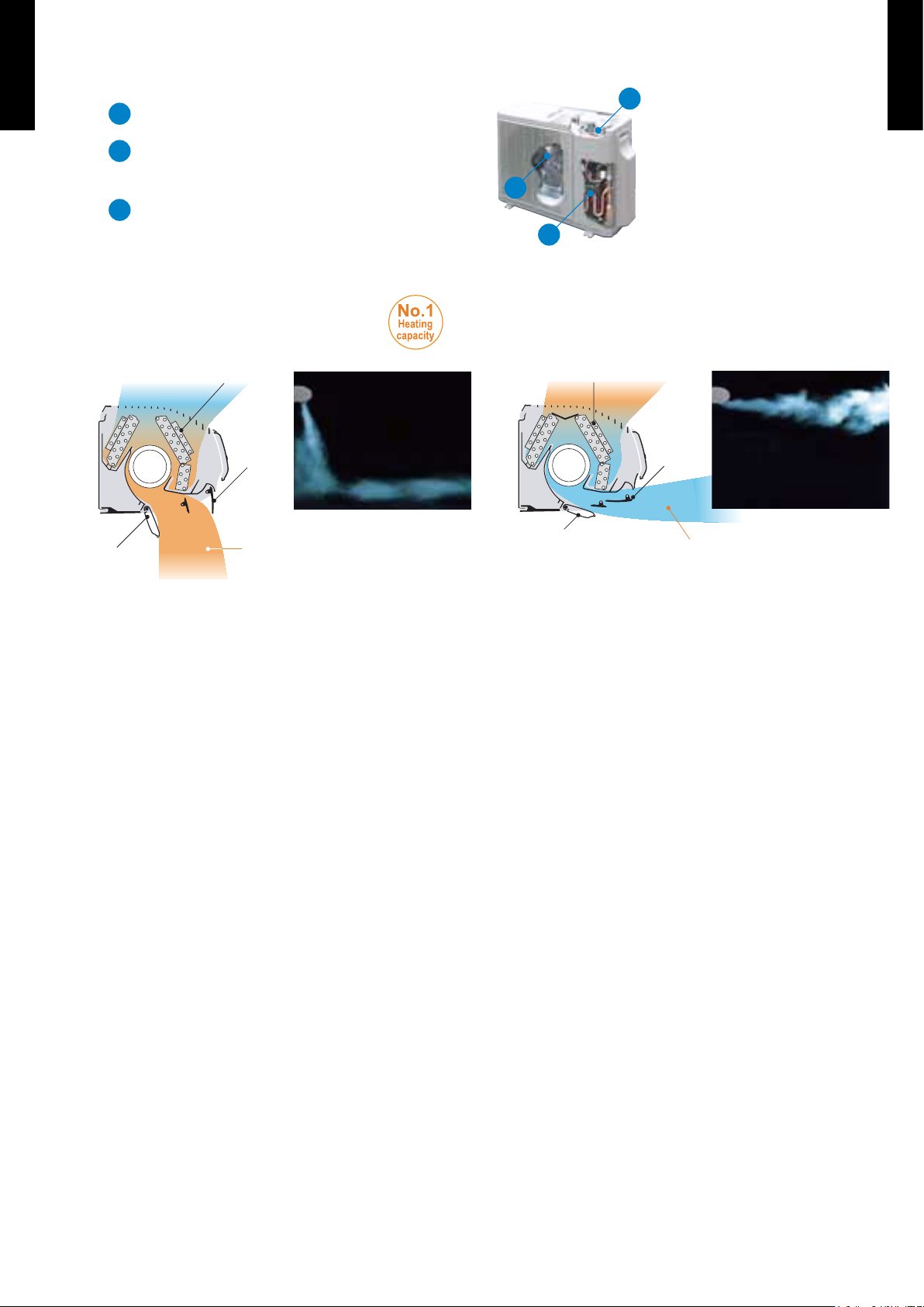
Front view
b
a
c
a
DC fan motor
b
V-PAM control
V-PAM technology makes a compressor more powerful.
c
DC compressor
"Vertical airow" provides
●
powerful oor level heating
"Horizontal airow" does not blow
●
cool air directly at the occupants
in the room
Increased heat exchange efficiency
Comfortable heating area
(Our company comparison)
Approx.
2.5 times*
*Compared to our conventional Model ASY13PSCCW
Air is blown directly downward
Power diffuser
(full open)
Big flap
Blown out horizontally
Power diffuser
Big flap
Increased heat exchange efficiency
Cooling range
(Our company comparison)
Approx.
1.7 times*
*Compared to our conventional Model ASY13PSCCW
Super quiet
●
Air ow mode can be set in 5 steps and more detailed air ow setting is possible.
Inner drying operation
●
This model is equipped with an inner drying function. After the power is turned off, the dry
operation starts inside the air conditioner. This prevents the growth of mold and bacterial
inside the air conditioner.
Low outdoor air temperature cooling correspondence
●
Corresponds to cooling operation at -10°C outdoor air temperature
Low outdoor air temperature heating correspondence
●
Corresponds to heating operation at -15°C outdoor air temperature
Corresponds to maximum 30m long piping (24TYPE)
●
Page 4
- (01 - 03) -
CEILING WALL TYPE
AW
Z14-24 LB
CEILING WALL TYPE
AW
Z14-24 LB
REMOTE CONTROLLER2.
WIRELESS REMOTE CONTROLLER2-1.
FEATURES
■
â
Four kinds of timer setup (ON / OFF / PROGRAM / SLEEP) are possible.
â
Four kinds of timers. Easy operation.
Built-in timers
●
Select from four different timer programs (On/Off/Program/Sleep).
Program timer
●
The program timer operates the ON and OFF timer once within a 24 hour period.
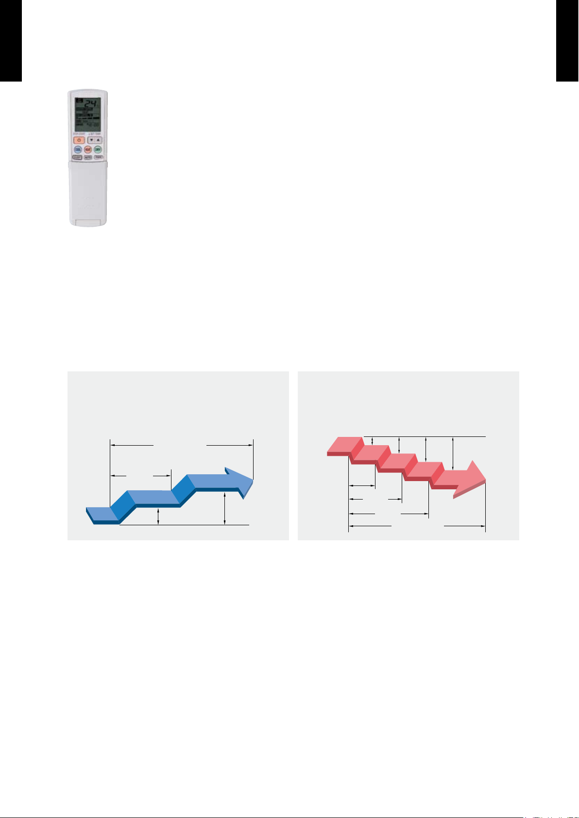
Sleep timer
●
The sleep timer function automatically corrects the temperature thermostat setting
according to the time setting to prevent excessive cooling and heating while sleeping.
Cooling operation/dry operation
60min.
1 °C
2 °C
When the sleep timer is set, the set temperature
automatically rises 1 °C every hour. The set
temperature can rise up to a maximum of 2 °C.
Heating operation
When the sleep timer is set, the set temperature
automatically drops 1 °C every 30 minutes. The
set temperature can drop to a maximum of 4 °C.
1 °C
30min.
60min.
90min.
2 °C
3 °C
4 °C
Timer setting
Timer setting
Page 5
- (01 - 04) -
CEILING WALL TYPE
AW
Z14-24 LB
CEILING WALL TYPE
AW
Z14-24 LB
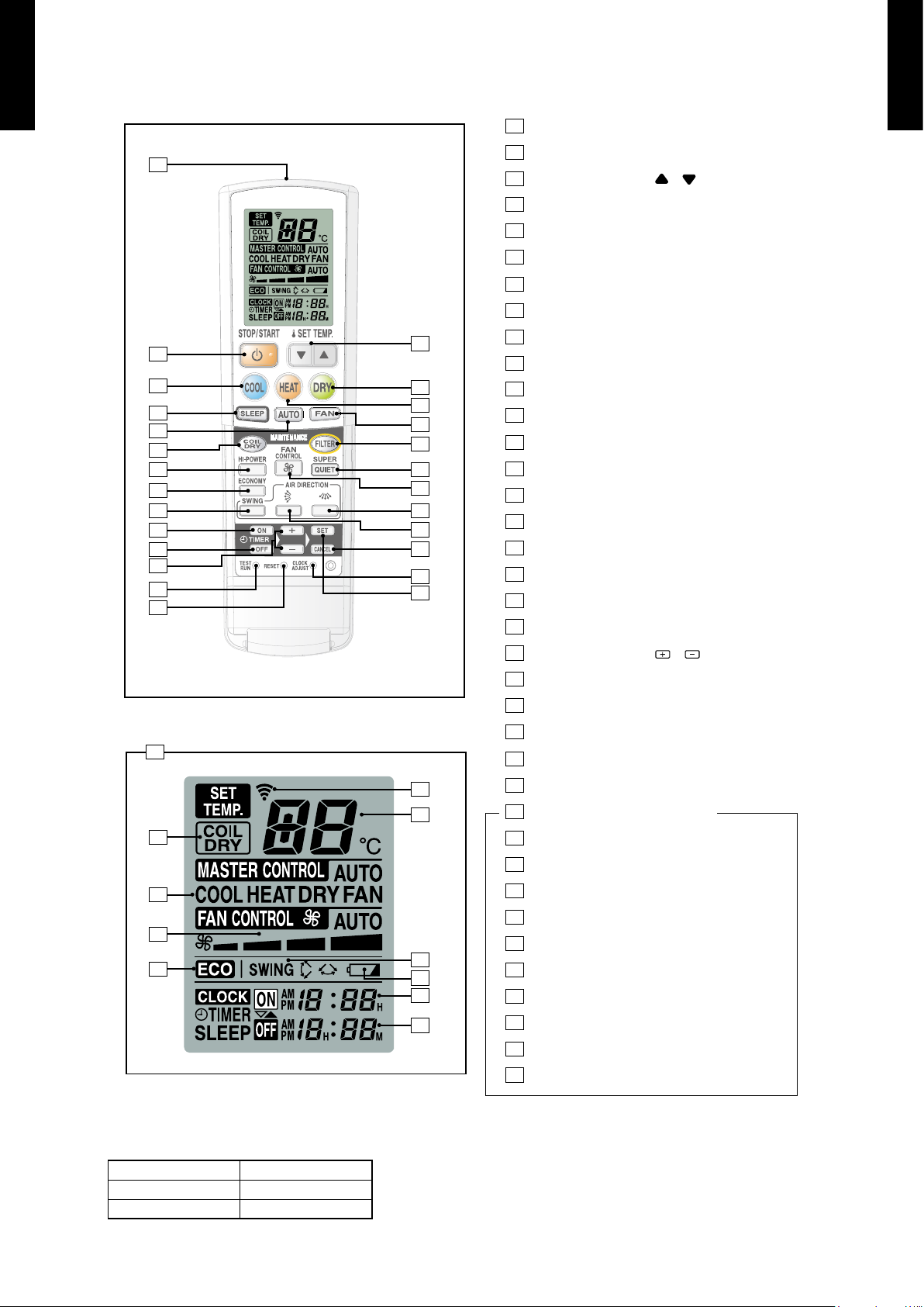
FUNCTIONS
■
Signal Transmitter
START/STOP button
SET TEMP. button ( )
COOL button
DRY button
HEAT button
SLEEP button
AUTO button
FAN button
COIL DRY button
FILTER button
HI-POWER button
SUPER QUIET button
FAN CONTROL button
ECONOMY button
SWING button
AIR DIRECTION (Left-Right) button
AIR DIRECTION (Up-Down) button
ON TIMER button
OFF TIMER button
SET TIME buttons ( )
SET (TIMER) button
CANCEL (TIMER) button
TEST RUN button
RESET button
CLOCK ADJUST button
Remote Control Unit Display
COIL DRY Display
Operating Mode Display
FAN CONTROL Display
ECONOMY Operation
Transmit Indicator
Temperature Display
SWING Display
Battery Indicator Display
ON TIMER Display
OFF TIMER Display
Display panel
/
/
27
1
2
4
7
8
10
12
15
16
19
20
21
24
25
28
29
30
31
3
5
6
9
11
13
14
17
18
23
26
22
32
33
34
35
36
37
1
2
3
4
5
6
7
8
9
10
11
12
13
14
15
16
17
18
19
20
21
22
23
24
25
26
27
28
29
30
31
33
34
35
36
37
32
SPECIFICATION
■
SIZE (H × W × D mm) 204 × 60 × 22
WEIGHT (g) 170
ACCESSORY Holder
Page 6
- (01 - 05) -
CEILING WALL TYPE
AW
Z14-24 LB
CEILING WALL TYPE
AW
Z14-24 LB
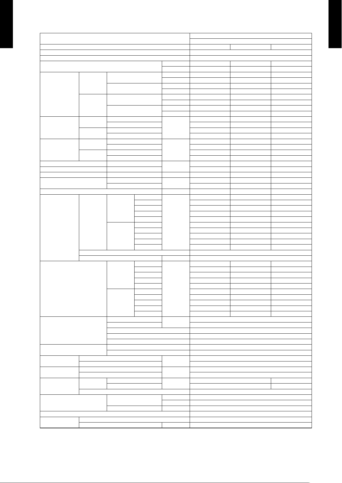
SPECIFICATIONS3.
Type
CEILING WALL
INVERTER HEAT PUMP
Model name AWZ14LBC AWZ18LBC AWZ24LBC
Power source 230V~ 50Hz
Available voltage range 198-264V~ 50Hz
European energy label
Cooling A A A
Heating A A A
Capacity
Cooling
Rated
kW 4.20 5.20 7.10
BTU/h 14,3 00 17, 70 0 24,200
Min.-Max.
kW 0.9-5.3 0.9-5.9 0.9-8.0
BTU/h 3,10 0-18,10 0 3,10 0- 20,10 0 3,100-27,300
Heating
Rated
kW 6.00 6.70 8.50
BTU/h 20,500 22,900 29,000
Min.-Max.
kW 0 .9 -9 .1 0.9 -9.7 0.9 -11.0
BTU/h 3,100-31,000 3 ,10 0- 33 ,10 0 3,100-37,500
Input power
Cooling
Rated
kW
1.02 1.58 2.21
Min.-Max. 0.09 -1.75 0.09-2.00 0.11- 2. 62
Heating
Rated 1.35 1.63 2.35
Min.-Max. 0.09-2.95 0.09-3.20 0.11-3.68
Current
Cooling
Rated
A
4.5 6.9 9.7
Ma x.* 8.5 8.5 12.5
Heating
Rated 5.9 7. 2 10.3
Ma x.* 14.0 14.0 1 7.5
EER Cooling
kW/kW
4.1 2 3.29 3.21
COP Heating 4.44 4.11 3.62
SENSIBLE CAPACITY Cooling kW 2.80 3.30 5.1 0
POWER FACTOR
Cooling
%
98 99 99
Heating 99 99 99
Moisture removal l/h (pints/h) 2.1 (3.7) 2.8 (4.9) 3.0 (5.3)
Fan
Airow rate
Cooling
High
m
3
/h
850 850 880
Med 760 760 780
Low 580 580 700
Quiet 465 465 620
S-Quiet 365 365 560
Heating
High 940 940 980
Med 740 74 0 880
Low 605 605 780
Quiet 510 510 700
S-Quiet 390 390 605
Type × Q'ty Cross ow fan × 1
Motor output W 72
Sound pressure level
Cooling
High
dB (A)
46 46 47
Med 43 43 43
Low 35 35 40
Quiet 29 29 36
S-Quiet 24 24 32
Heating
High 46 46 47
Med 39 39 43
Low 34 34 40
Quiet 29 29 36
S-Quiet 24 24 32
Heat exchanger type
Dimensions (H × W × D)
mm
315 × 750 × 26.6
Fin pitch 1.2
Rows × Stages 2 × 15
Pipe type Copper
Fin type Aluminium
Enclosure
Material Polystyrene
Colour White
Dimensions
(H × W × D)
Net
mm
250 × 899 × 298
Gross 356 × 960 × 378
Weight
Net
kg (lb.)
13.5 (30)
Gross 17 (37)
Connection pipe
Size
Liquid
mm
Φ6.35 (Φ1/4 in.) Φ6.35 (Φ1/4 in.)
Gas Φ12.7 (Φ1/2 in.) Φ15.88 (Φ5/8 in.)
Method Flare
Operation range
Cooling
°C 18 to 32
%RH 80 or less
Heating °C 30 or less
Remote controller type Wireless
Drain pipe
Material PP+LLDPE
Size mm Outer diameter : 29 / Inner diameter : 13.6
Note :
Specications are based on the following conditions.
Cooling : Indoor temperature of 27°CDB / 19°CWB. and outdoor temperature of 35°CDB/24°CWB.
Heating : Indoor temperature of 20°CDB / 15°CWB. and outdoor temperature of 7°CDB/6°CWB.
Pipe length : 7.5 m, Height difference : 0 m. (Outdoor unit - Indoor unit)
The maximum current is the maximum value when operated within the operation range (temperature).
* The maximum current is the total current of indoor unit and outdoor unit.
Page 7
- (01 - 06) -
CEILING WALL TYPE
AW
Z14-24 LB
CEILING WALL TYPE
AW
Z14-24 LB
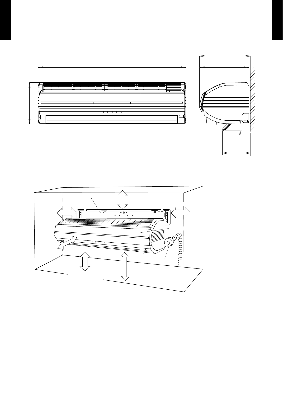
DIMENSIONS4.
MODEL : AW
■
Z14LB , AWZ18LB , AWZ24LB
(Unit : mm)
300
298
899
250
170
40
INSTALLATION PLACE
■
6.7 cm or more
Wall hook bracket
6.5 cm or more
5 cm or more
(Wall cap)
150 cm or more
230 cm or more
Open panel
* The filters come out
of the front of the
indoor unit.
Front panel
40 cm or more
Page 8

- (01 - 07) -
CEILING WALL TYPE
AW
Z14-24 LB
CEILING WALL TYPE
AW
Z14-24 LB
WIRING DIAGRAMS5.
MODEL : AW
■
Z14LB , AWZ18LB
TO OUTDOOR UNIT
RED
WHITE
WHITE
WHITE
WHITE
WHITE
WHITE
WHITE
WHITE
WHITE
RED
WHITE
WHITE
WHITE
WHITE
WHITE
WHITE
WHITE
WHITE
WHITE
WHITE
WHITE
WHITE
WHITE
WHITE
WHITE
RED
RED
RED
WHITE
WHITE
WHITE
WHITE
WHITE
WHITE
WHITE
WHITE
WHITE
WHITE
WHITE
WHITE
WHITE
WHITE
WHITE
WHITE
WHITE
RED
WHITE
WHITE
WHITE
WHITE
WHITE
WHITE
WHITE
WHITE
WHITE
BLUE
YELLOW
WHITE
BLACK
RED
WHITE
WHITE
WHITE
WHITE
RED
RED
WHITE
WHITE
WHITE
WHITE
BLUE
PURPLE
GRAY
WHITE
BLACK
BROWN
RED
ORANGE
YELLOW
GREEN
BLACK
BLACK
BLACK
BLACK
BLACK
WHITE
BLUE
RED
RED
WHITE
WHITE
WHITE
RED
WHITE
WHITE
GREEN / YELLOW
WHITE
BLACK
RED
GRAY
BLUE
BROWN
RED
WHITE
WHITE
WHITE
WHITE
WHITE
WHITE
WHITE
WHITE
RED
RED
WHITE
WHITE
WHITE
WHITE
WHITE
RED
RED
WHITE
WHITE
WHITE
BROWN
RED
ORANGE
YELLOW
RED
BROWN
ORANGE
YELLOW
CN205
CN206
CN201
CN200 CN203 CN202
CN204
CN3
CN4
CN16
CN9
CN6 CN7 CN17
CN12
CN210
CN15
CN11
CN208
20
19
18
17
16
15
14
13
12
11
10
9
8
7
6
5
4
3
2
1
20
19
18
17
16
15
14
13
12
11
10
9
8
7
6
5
4
3
2
1
10
9
8
7
6
5
4
3
2
1
11
10
9
8
7
6
5
4
3
2
1
11
10
9
8
7
6
5
4
3
2
1
10
9
8
7
6
5
4
3
2
1
10
9
8
7
6
5
4
3
2
1
18
17
16
15
14
13
12
11
10
9
8
7
6
5
4
3
2
1
18
17
16
15
14
13
12
11
10
9
8
7
6
5
4
3
2
1
6
5
4
3
2
1
6
5
4
3
2
1
5
4
3
2
1
5
4
3
2
1
5
4
3
2
1
5
4
3
2
1
5
4
3
2
1
5
4
3
2
1
5
4
3
2
1
5
4
3
2
1
5432
1
5
4
3
2
1
6
7
8
9
10
2
1
5432
1
5432
1
5432
1 6
5432
1
5432
1
432
1
2
1
8
7
6
2
1
5
432
1
2
1
876
5
432
1
8
765
432
1
5
4
32
1
2
1
4
32
1
4
32
1
32
1
32
1
32
1
2
1
THERMAL
FUSE 102
NL3
4
3
3
1
1
3
THERMAL
FUSE 102
THERMAL
FUSE 102
POWER RELAY
SWITCH (LEFT)
SWITCH
(RIGHT)
AIR FILTER (LEFT)
AIR FILTER (RIGHT)
TM1 TM2
M
M
POWER
SOURCE
TERMINAL
TEST
ROOM TEMPERATURE THERMISTOR
PIPE TEMPERATURE THERMISTOR
F M
M
M
M
M
DIFFUSER
LOUVER Z
LOUVER U
RIGHT-LEFT LOUVER
CONNECTOR (WHITE)
CONNECTOR (WHITE)
CONNECTOR (RED)
CONNECTOR (RED)
UV-LED
UNIT
RECEIVER PCB
W3
CONTROLLER PCB
INDICATOR PCB
CONNECTOR BOARD
Page 9

- (01 - 08) -
CEILING WALL TYPE
AW
Z14-24 LB
CEILING WALL TYPE
AW
Z14-24 LB
MODEL : AW
■
Z24LB
WHITE
WHITE
WHITE
WHITE
WHITE
WHITE
WHITE
WHITE
WHITE
WHITE
WHITE
WHITE
WHITE
WHITE
WHITE
WHITE
RED
RED
RED
RED
RED
WHITE
WHITE
WHITE
WHITE
WHITE
WHITE
WHITE
WHITE
BROWN
ORANGE
YELLOW
GREEN
BLUE
PURPLE
GRAY
WHITE
BLACK
WHITE
WHITE
WHITE
WHITE
WHITE
WHITE
WHITE
WHITE
RED
WHITE
WHITE
WHITE
WHITE
WHITE
WHITE
WHITE
WHITE
RED
WHITE
WHITE
WHITE
WHITE
WHITE
WHITE
WHITE
WHITE
WHITE
RED
RED
WHITE
WHITE
WHITE
WHITE
WHITE
WHITE
WHITE
WHITE
WHITE
BLUE
YELLOW
WHITE
BLACK
RED
WHITE
WHITE
WHITE
WHITE
WHITE
WHITE
WHITE
WHITE
RED
RED
WHITE
RED
WHITE
WHITE
WHITE
WHITE
RED
WHITE
RED
WHITE
WHITE
BROWN
RED
ORANGE
YELLOW
BROWN
RED
ORANGE
YELLOW
WHITE
WHITE
WHITE
WHITE
WHITE
RED
RED
BLUE
WHITE
BLACK
RED
BLACK
BLACK
BLACK
BLACK
20
19
18
17
16
15
14
13
12
11
10
9
8
7
6
5
4
3
2
1
11
10
9
8
7
6
5
4
3
2
1
20
19
18
17
16
15
14
13
12
11
10
9
8
7
6
5
4
3
2
1
11
10
9
8
7
6
5
4
3
2
1
10
9
8
7
6
5
4
3
2
1
18
17
16
15
14
13
12
11
10
9
8
7
6
5
4
3
2
1
18
17
16
15
14
13
12
11
10
9
8
7
6
5
4
3
2
1
5
4
3
2
1
5
4
3
2
1
5
4
3
2
1
5
4
3
2
1
5
4
3
2
1
5
4
3
2
1
5
4
3
2
1
5
4
3
2
1
6
5
4
3
2
1
6
5
4
3
2
1
10
9
8
7
6
5
4
3
2
1
10
9
8
7
6
5
4
3
2
1
10
9
8
7
6
5
4
3
2
1
1 2 3 4 567
8
1 2 3 4 567
8
1 2 3 4 561 2 3 4
1
2
1
21 2 3 4 5
1 2 3 4 5
1 2 3 4 5
1 2 3 4 5 1 2
1 2
1 2 3 4 567
8
1 2 3 4 5
1 2 3 4 5
1 2 3 4
1 2 3 4
1 2 3
1 2
3
1 2 3
1 2 1 2
CN205
TEST
CN12CN17
CN7
CN6
CN3
CN4
CN16
CN9
CN206
CN15
CN11
CN201
CN200 CN203
CN202 CN204
CN208
CN210
3
3
1
1
SW (LEFT)
SW (RIGHT)
THERMAL
FUSE 102
AIR FILTER (LEFT)
AIR FILTER (RIGHT)
THERMAL
FUSE 102
TM1 TM2
LOUVER U
LOUVER Z
LOUVER
(RIGHT-LEFT)
DIFFUSER
FAN MOTOR
CONNECTOR (WHITE)
CONNECTOR (WHITE)
CONNECTOR (RED)
CONNECTOR (RED)
ROOM TEMP. THERMISTOR
PIPE TEMP. THERMISTOR
RECEIVER PCB
UV-LED UNIT
W3
CONTROLLER PCB
F M
M
M
CONNECTOR PCB
INDICATOR PCB
M
M
M
M
TM4
WHITE
BLACK
RED
THERMAL
FUSE 102
TERMINAL
N
L 3
TO OUTDOOR UNIT
Page 10
- (01 - 09) -
CEILING WALL TYPE
AW
Z14-24 LB
CEILING WALL TYPE
AW
Z14-24 LB
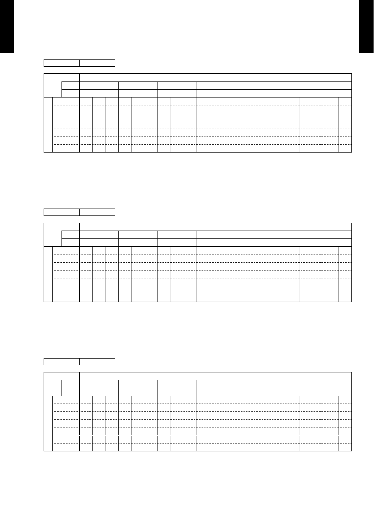
CAPACITY TABLE6.
COOLING CAPACITY6-1.
MODEL : AW
■
Z14LB
AFR 14. 2
Indoor temperature
°CDB 18 21 23 25 27 29 32
°CWB 12 15 16 18 19 21 23
Outdoor temperature
°CDB TC
SHC
PI TC
SHC
PI TC
SHC
PI TC
SHC
PI TC
SHC
PI TC
SHC
PI TC
SHC
PI
20 3.90 2.78 0.71 4.35 2.80 0.72 4.49 3.04 0.72 4.79 3.05 0.73 4.94 3.29 0.74 5.23 3.28 0.74 5.53 3.49 0.75
25 3.72 2.65 0.80 4.15 2.67 0.81 4.29 2.90 0.82 4.57 2.91 0.83 4.71 3 .14 0.83 4.99 3.13 0.84 5.28 3.33 0.85
30 3.53 2.51 0.89 3.93 2.53 0.90 4.06 2.75 0.91 4.33 2.76 0.92 4.46 2.98 0.92 4.73 2.96 0.93 5.00 3 .16 0.94
35 3.32 2.36 0.98 3.70 2.38 1.00 3.82 2.58 1.00 4.07 2.59 1.01 4.20 2.80 1.02 4.45 2.79 1.03 4.70 2.97 1.0 4
40 2.85 2.03 0.94 3 .18 2.04 0.95 3.28 2.22 0.96 3.50 2.23 0.97 3.61 2 .41 0.97 3.83 2.40 0.98 4.04 2.55 0.99
43 2.63 1.87 0.93 2.93 1.8 8 0.95 3.03 2.05 0.95 3.23 2.05 0.96 3.33 2.22 0.97 3.53 2.21 0.98 3.73 2.35 0.98
AFR : Air ow rate (m
3
/min)
TC : Total capacity (kW)
SHC : Sensible Heat capacity (kW)
PI : Power Input (kW)
MODEL : AW
■
Z18LB
AFR 14. 2
Indoor temperature
°CDB 18 21 23 25 27 29 32
°CWB 12 15 16 18 19 21 23
Outdoor temperature
°CDB TC
SHC
PI TC
SHC
PI TC
SHC
PI TC
SHC
PI TC
SHC
PI TC
SHC
PI TC
SHC
PI
20 4.83 3.27 1.10 5.38 3.29 1.12 5.56 3.58 1.12 5.93 3.59 1.13 6.11 3.88 1.14 6.48 3.86 1.15 6.85 4.12 1.16
25 4.61 3 .12 1.24 5.1 3 3.14 1. 26 5.31 3.42 1. 27 5.66 3.43 1.28 5.83 3.70 1.29 6.18 3.69 1.30 6.53 3.93 1.31
30 4.37 2.96 1.38 4.86 2.98 1.4 0 5.03 3.24 1.41 5.36 3.25 1.42 5.53 3. 51 1.43 5.86 3.49 1.44 6.1 9 3.72 1. 46
35 4 .11 2.79 1.52 4.58 2.80 1.55 4.73 3.05 1. 56 5.04 3.06 1.57 5.20 3.30 1.58 5.51 3.29 1.60 5.82 3.50 1.61
40 3.53 2.39 1. 45 3.93 2.41 1. 47 4.07 2.62 1. 48 4.33 2.63 1.5 0 4.47 2.84 1. 50 4.74 2.82 1. 52 5.00 3.01 1.53
43 3.26 2.21 1.44 3.63 2.22 1.47 3.75 2.41 1.47 4.00 2.42 1.49 4 .12 2.62 1.5 0 4.37 2.60 1.51 4.62 2.77 1. 53
AFR : Air ow rate (m
3
/min)
TC : Total capacity (kW)
SHC : Sensible Heat capacity (kW)
PI : Power Input (kW)
MODEL : AW
■
Z24LB
AFR 14.7
Indoor temperature
°CDB 18 21 23 25 27 29 32
°CWB 12 15 16 18 19 21 23
Outdoor temperature
°CDB TC
SHC
PI TC
SHC
PI TC
SHC
PI TC
SHC
PI TC
SHC
PI TC
SHC
PI TC
SHC
PI
20 5.79 4.44 1.15 6.45 4.47 1.17 6.67 4.86 1.17 7.11 4.87 1.19 7.33 5.26 1.19 7.77 5.24 1.20 8.20 5.58 1.22
25 5.52 4.24 1.33 6.15 4.26 1.35 6.36 4.63 1.36 6.78 4.65 1.37 6.99 5.02 1.38 7.41 5.00 1.39 7.83 5.33 1.41
30 5.94 4.56 1.91 6.62 4.59 1.94 6.84 4.99 1.95 7.30 5.00 1.97 7.52 5.40 1.98 7.97 5.38 2.00 8.42 5.73 2.02
35 5.61 4.30 2.13 6.25 4.33 2.17 6.46 4.71 2.18 6.89 4.72 2.20 7.10 5.10 2.21 7.53 5.08 2.23 7.95 5.41 2.25
40 5.26 4.04 2.36 5.86 4.06 2.39 6.06 4.42 2.41 6.46 4.43 2.43 6.66 4.78 2.44 7.06 4.76 2.47 7.46 5.08 2.49
43 5.05 3.88 2.50 5.63 3.90 2.53 5.82 4.24 2.55 6.20 4.25 2.57 6.39 4.59 2.59 6.78 4.57 2.61 7.16 4.87 2.64
AFR : Air ow rate (m
3
/min)
TC : Total capacity (kW)
SHC : Sensible Heat capacity (kW)
PI : Power Input (kW)
Page 11
- (01 - 10) -
CEILING WALL TYPE
AW
Z14-24 LB
CEILING WALL TYPE
AW
Z14-24 LB
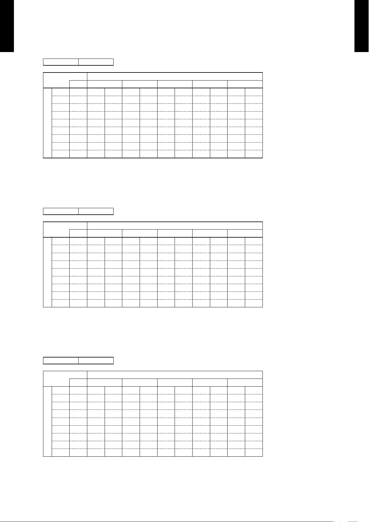
HEATING CAPACITY6-2.
MODEL : AW
■
Z14LB
AFR 15.7
Indoor temperature
°CDB 16 18 20 22 24
Outdoor temperature
°CDB °CWB TC PI TC PI TC PI TC PI TC PI
-15 -16 6.03 2.14 5.89 2.16 5.74 2.18 5.60 2.21 5.46 2.23
-10 -11 7.04 2.48 6.87 2.50 6.70 2.53 6.54 2.56 6.37 2.58
-5 -7 7.89 2.63 7.70 2.65 7.51 2.68 7.33 2.71 7.14 2.73
0 -2 9.10 2.83 8.88 2.86 8.67 2.89 8.45 2.92 8.23 2.95
5 3 9.14 2.25 8.92 2.27 8.71 2.30 8.49 2.32 8.27 2.34
7 6 9.56 2.23 9.33 2.26 9.10 2.28 8.87 2.30 8.65 2.33
10 8 9.32 2.22 9.10 2.24 8.88 2.27 8.66 2.29 8.43 2.31
15 10 9.14 1.91 8.92 1.93 8.71 1.95 8.49 1.97 8.27 1.99
AFR : Air ow rate (m
3
/min)
TC : Total capacity (kW)
PI : Power Input (kW)
MODEL : AW
■
Z18LB
AFR 15.7
Indoor temperature
°CDB 16 18 20 22 24
Outdoor temperature
°CDB °CWB TC PI TC PI TC PI TC PI TC PI
-15 -16 6.43 2.33 6.28 2.35 6.12 2.38 5.97 2.40 5.82 2.42
-10 -11 7.50 2.70 7.32 2.72 7.14 2.75 6.97 2.78 6.79 2.81
-5 -7 8.41 2.86 8.21 2.88 8.01 2.91 7.81 2.94 7.61 2.97
0 -2 9.70 3.08 9.47 3.11 9.24 3.14 9.01 3.17 8.78 3.20
5 3 9.75 2.45 9.51 2.47 9.28 2.50 9.05 2.52 8.82 2.55
7 6 1 0.19 2.43 9.94 2.46 9.70 2.48 9.46 2.50 9.22 2.53
10 8 9.94 2.42 9.70 2.44 9.46 2.47 9.23 2.49 8.99 2.51
15 10 9.74 2.08 9.51 2.10 9.28 2.12 9.05 2.14 8.82 2.16
AFR : Air ow rate (m
3
/min)
TC : Total capacity (kW)
PI : Power Input (kW)
MODEL : AW
■
Z24LB
AFR 16.3
Indoor temperature
°CDB 16 18 20 22 24
Outdoor temperature
°CDB °CWB TC PI TC PI TC PI TC PI TC PI
-15 -16 7.57 3.21 7.39 3.25 7.21 3.28 7.03 3.31 6.85 3.34
-10 -11 8.69 3.33 8.48 3.36 8.28 3.40 8.07 3.43 7.86 3.46
-5 -7 9.81 3.44 9.57 3.48 9.34 3.51 9.11 3.55 8.87 3.58
0 -2 10.58 3.54 10.33 3.57 10.08 3.61 9.82 3.65 9.57 3.68
5 3 10.02 3.50 9.78 3.54 9.54 3.57 9.30 3.61 9.06 3.64
7 6 11.55 3.47 11. 28 3.50 11.00 3.54 10.73 3.58 10.45 3.61
10 8 12.49 3.47 12.20 3.50 11.90 3.54 11.60 3.57 11. 30 3.61
15 10 12.00 3.02 11.71 3.05 11.42 3.08 11.14 3.11 10.85 3.14
AFR : Air ow rate (m
3
/min)
TC : Total capacity (kW)
PI : Power Input (kW)
Page 12

- (01 - 11) -
CEILING WALL TYPE
AW
Z14-24 LB
CEILING WALL TYPE
AW
Z14-24 LB
FAN PERFORMANCE7.
AIR VELOCITY DISTRIBUTION7-1.
MODEL : AW
■
Z14LB , AWZ18LB
Note :
Fan speed : High
Voltage : 230V
TOP VIEW
FLOW CONTROL PANEL : Horiz.
LOUVER : Center
TOP VIEW
FLOW CONTROL PANEL : Horiz.
LOUVER : Right & Left
SIDE VIEW
FLOW CONTROL PANEL : Horiz.
LOUVER : Center
SIDE VIEW
FLOW CONTROL PANEL : Vert.
LOUVER : Center
Operation mode :FAN
2
1
0
1
2
0 1 2 3 4 5 6 7 8
2.0
1.0
0.5
3
2
1
0
1
2
3
0 1 2 3 4 5 6 7 8
0.5
1.0
1.0
2.0
2.0
0.5
0
1
2
3
0 1 2 3 4 5 6 7 8
2.0
1.0
0.5
0
1
2
3
0 1 2 3 4 5 6 7 8
2.0
1.0
0.5
(m)
(m)
Unit : m/s
(m)
(m)
Unit : m/s
(m)
(m)
Unit : m/s
(m)
Unit : m/s
(m)
Page 13

- (01 - 12) -
CEILING WALL TYPE
AW
Z14-24 LB
CEILING WALL TYPE
AW
Z14-24 LB
MODEL : AW
■
Z24LB
Note :
Fan speed : High
Voltage : 230V
TOP VIEW
FLOW CONTROL PANEL : Horiz.
LOUVER : Center
TOP VIEW
FLOW CONTROL PANEL : Horiz.
LOUVER : Right & Left
SIDE VIEW
FLOW CONTROL PANEL : Horiz.
LOUVER : Center
SIDE VIEW
FLOW CONTROL PANEL : Vert.
LOUVER : Center
Operation mode :FAN
2
1
0
1
2
0 1 2 3 4 5 6 7 8
2.0
1.0
0.5
3
2
1
0
1
2
3
0 1 2 3 4 5 6 7 8
0.5
1.0
1.0
2.0
2.0
0.5
0
1
2
3
0 1 2 3 4 5 6 7 8
2.0
1.0
0.5
0
1
2
3
0 1 2 3 4 5 6 7 8
2.0
1.0
0.5
(m)
(m)
Unit : m/s
(m)
(m)
Unit : m/s
(m)
Unit : m/s
(m)
(m)
(m)
Unit : m/s
Page 14

- (01 - 13) -
CEILING WALL TYPE
AW
Z14-24 LB
CEILING WALL TYPE
AW
Z14-24 LB
AIR FLOW7-2.
MODEL : AW
■
Z14LB , AWZ18LB
COOLING
●
Fan speed
Number of
rotations (r.p.m)
Airow
HIGH 1450
850 m
3
/h
236 l/s
500 CFM
MED 1320
760 m
3
/h
211 l/s
447 CFM
LOW 1050
580 m
3
/h
161 l/s
341 CFM
QUIET 880
465 m
3
/h
129 l/s
274 CFM
SUPERQUIET 730
365 m
3
/h
101 l/s
215 CFM
HEATI NG
●
Fan speed
Number of
rotations (r.p.m)
Airow
HIGH 1650
940 m
3
/h
261 l/s
553 CFM
MED 1350
740 m
3
/h
206 l/s
435 CFM
LOW 1150
605 m
3
/h
168 l/s
356 CFM
QUIET 1000
510 m
3
/h
142 l/s
300 CFM
SUPERQUIET 820
390 m
3
/h
108 l/s
230 CFM
Page 15

- (01 - 14) -
CEILING WALL TYPE
AW
Z14-24 LB
CEILING WALL TYPE
AW
Z14-24 LB
MODEL : AW
■
Z24LB
COOLING
●
Fan speed
Number of
rotations (r.p.m)
Airow
HIGH 1500
880 m
3
/h
244 l/s
518 CFM
MED 1370
780 m
3
/h
217 l/s
459 CFM
LOW 125 0
700 m
3
/h
194 l/s
412 CFM
QUIET 113 0
620 m
3
/h
172 l/s
365 CFM
SUPERQUIET 1030
560 m
3
/h
156 l/s
330 CFM
HEATI NG
●
Fan speed
Number of
rotations (r.p.m)
Airow
HIGH 170 0
980 m
3
/h
272 l/s
577 CFM
MED 1540
880 m
3
/h
244 l/s
518 CFM
LOW 139 0
780 m
3
/h
217 l/s
459 CFM
QUIET 1260
700 m
3
/h
194 l/s
412 CFM
SUPERQUIET 1120
605 m
3
/h
168 l/s
356 CFM
Page 16

- (01 - 15) -
CEILING WALL TYPE
AW
Z14-24 LB
CEILING WALL TYPE
AW
Z14-24 LB
OPERATION NOISE8.
NOISE LEVEL CURVE8-1.
MODEL : AW
■
Z14LB
COOLING
●
HEATI NG
●
0
10
20
30
40
50
60
70
80
63 125 250 500 1000 2000 4000 8000
Octave band center frequency ,Hz
Octave band sound pressure level, dB:(0dB=20μPa)
NC-20
NC-40
NC-50
NC-60
NC-30
NC-15
NC-25
NC-35
NC-45
NC-55
NC-65
High
Super Quiet
0
10
20
30
40
50
60
70
80
63 125 250 500 1000 2000 4000 8000
Octave band center frequency ,Hz
Octave band sound pressure level, dB:(0dB=20μPa)
NC-20
NC-40
NC-50
NC-60
NC-30
NC-15
NC-25
NC-35
NC-45
NC-55
NC-65
High
Super Quiet
MODEL : AW
■
Z18LB
COOLING
●
HEATI NG
●
0
10
20
30
40
50
60
70
80
63 125 250 500 1000 2000 4000 8000
Octave band center frequency ,Hz
Octave band sound pressure level, dB:(0dB=20μPa)
NC-20
NC-40
NC-50
NC-60
NC-30
NC-15
NC-25
NC-35
NC-45
NC-55
NC-65
High
Super Quiet
0
10
20
30
40
50
60
70
80
63 125 250 500 1000 2000 4000 8000
Octave band center frequency ,Hz
Octave band sound pressure level, dB:(0dB=20μPa)
NC-20
NC-40
NC-50
NC-60
NC-30
NC-15
NC-25
NC-35
NC-45
NC-55
NC-65
High
Super Quiet
Page 17

- (01 - 16) -
CEILING WALL TYPE
AW
Z14-24 LB
CEILING WALL TYPE
AW
Z14-24 LB
MODEL : AW
■
Z24LB
COOLING
●
HEATI NG
●
0
10
20
30
40
50
60
70
80
63 125 250 500 1000 2000 4000 8000
Octave band center frequency ,Hz
Octave band sound pressure level, dB:(0dB=20μPa)
NC-20
NC-40
NC-50
NC-60
NC-30
NC-15
NC-25
NC-35
NC-45
NC-55
NC-65
High
Super Quiet
0
10
20
30
40
50
60
70
80
63 125 250 500 1000 2000 4000 8000
Octave band center frequency ,Hz
Octave band sound pressure level, dB:(0dB=20μPa)
NC-20
NC-40
NC-50
NC-60
NC-30
NC-15
NC-25
NC-35
NC-45
NC-55
NC-65
High
Super Quiet
Page 18

- (01 - 17) -
CEILING WALL TYPE
AW
Z14-24 LB
CEILING WALL TYPE
AW
Z14-24 LB
SOUND LEVEL CHECK POINT8-2.
MIC MIC
1m
0.8m
Page 19

- (01 - 18) -
CEILING WALL TYPE
AW
Z14-24 LB
CEILING WALL TYPE
AW
Z14-24 LB
ELECTRIC CHARACTERISTICS9.
Model Name AWZ14LB AWZ18LB AWZ24LB
Power Supply
Volt ag e V 230~
Frequency Hz 50
*1) Max Operating Current A 14.0 14.0 0.3 (Indoor unit)
*2) Wiring Spec.
Main Fuse (circuit
breaker) Current
A 20 20 ―
Connection Cable mm
2
2.0-3.5 2.0-3.5 1.5-2.5
Limited wiring length m 21 21 31
*1) The maximum current is the total current of indoor unit and outdoor unit.
(14, 18 model only)
*2) Wiring Spec.
Selected Sample
(Selected based on Japan Electrotechnical Standard and Codes Committee E0005)
Page 20

- (01 - 19) -
CEILING WALL TYPE
AW
Z14-24 LB
CEILING WALL TYPE
AW
Z14-24 LB
SAFETY DEVICES10.
Protection form
Model
AWZ14LB AWZ18LB AWZ24LB
Circuit protection Current fuse (PCB) 3.15A 250V
Terminal protection Current (thermal) fuse 3A 250V 102°C
Fan motor protection Thermal protection program
130
+20
-20
°C OFF
100
+20
-20
°C ON
Page 21

2. SINGLE TYPE :
AOZ14LBC
AOZ18LBC
AOZ24LBT
OUTDOOR UNIT
D2D_AO024E/01
2008.07.24
R410A
Page 22

- (02 - 01) -
OUTDOOR UNIT
AO
Z14-24LB
OUTDOOR UNIT
AO
Z14-24LB
SPECIFICATIONS1.
Type INVERTER HEAT PUMP
Model name AOZ14LBC AOZ18LBC AOZ24LBT
Power source 230V~ 50Hz
Available voltage range 198-264V~ 50Hz
Starting current A 5.9 7. 2 10.3
Fan
Airow rate
Cooling
m3/h
1,910 1,910 3,600
Heating 1,910 1,910 3,320
Type × Q'ty Propeller fan × 1
Motor output W 60 103
Sound pressure level
Cooling
dB (A)
46 47 53
Heating 47 48 54
Heat exchanger type
Dimensions (H × W × D)
mm
546 × 876 × 36.4 798 × 900 × 36.4
Fin pitch 1.3 1.3
Rows × Stages 2 × 26 2 × 38
Pipe type Copper
Fin type Aluminium
Compressor
Type × Q'ty Rotary × 1
Motor output W 900 1,700
Refrigerant
Type R410A
Charge g 1,350 1,900
Refrigerant oil Type POE (α68SZ) POE (FV50S)
Enclosure
Material Steel
Colour Beige
Dimensions (H × W × D)
Net
mm
578 × 790 × 300 830 × 900 × 330
Gross 648 × 910 × 380 970 × 1,050 × 445
Weight
Net
kg (lb.)
39 (86) 62 (137)
Gross 43 (95) 70 (154)
Connection pipe
Size
Liquid
mm
Φ6.35 (Φ1/4 in.) Φ6.35 (Φ1/4 in.)
Gas Φ12.7 (Φ1/2 in.) Φ15.88 (Φ5/8 in.)
Method Flare
Max. length
m
20 (chargeless:15) 30 (chargeless:15)
Max. height difference 15 20
Operation range
Cooling
°C
-10 to 43
Heating -15 to 24
Note :
Specications are based on the following conditions.
Cooling : Indoor temperature of 27°CDB / 19°CWB. and outdoor temperature of 35°CDB/24°CWB.
Heating : Indoor temperature of 20°CDB / 15°CWB. and outdoor temperature of 7°CDB/6°CWB.
Pipe length : 7.5 m, Height difference : 0 m. (Outdoor unit - Indoor unit)
Page 23

- (02 - 02) -
OUTDOOR UNIT
AO
Z14-24LB
OUTDOOR UNIT
AO
Z14-24LB
DIMENSIONS2.
MODEL : AO
■
Z14LB , AOZ18LB
(Unit : mm)
Top view
Front view Side view
Bottom view
578
10
300
60
790
540
177
189
121
184
320
Air flow
Drain pipe
mounting place
(20)
4- 10mm hole
INSTALLATION PLACE
■
600 mm or more
100 mm or more
300 mm or more
100 mm or more
300 mm or more
(Service space)
AIR
If the space is larger that is stated, the condition will be the same as that are no obstacles.
Page 24

- (02 - 03) -
OUTDOOR UNIT
AO
Z14-24LB
OUTDOOR UNIT
AO
Z14-24LB
MODEL : AO
■
Z24LB
(Unit : mm)
900
650
830
370
99
196
21
9
77
31 330
400
170
147
12
Top view
Front view
Side view
Bottom view
Air flow
Drain cap
mounting places
Drain pipe
mounting place
4- 12mm hole
INSTALLATION PLACE
■
When there are obstacles
at the back or front sides.
When there are obstacles
at the back, side(s), and top.
When there are obstacles at the
back, side with the installation of
more than one unit.
600 mm
or more
250 mm
or more
250 mm
or more
300 mm
or more
600 mm or more
100 mm
or more
300 mm
or more
100 mm
or more
250 mm or more
(Service space)
AIR
AIR
AIR
Page 25

- (02 - 04) -
OUTDOOR UNIT
AO
Z14-24LB
OUTDOOR UNIT
AO
Z14-24LB
REFRIGERANT CIRCUIT3.
MODEL : AO
■
Z14LB , AOZ18LB
2-Way Valve
Strainer
Strainer
Muffler
Muffler
Receiver
Heat exchanger B
( INDOOR )
3-Way Valve
4-Way Valve
Pulse motor valve
Heat exchanger
( INDOOR )
Heat exchanger
( OUTDOOR )
Accumulator
Compressor
Cooling
Heating
Refrigerant pipe diameter
Liquid pipe : 6.35 mm
Gas pipe : 12.7 mm
Page 26

- (02 - 05) -
OUTDOOR UNIT
AO
Z14-24LB
OUTDOOR UNIT
AO
Z14-24LB
MODEL : AO
■
Z24LB
3-Way valve
(Small)
3-Way valve
(Large)
Strainer
Strainer
Muffler
Pressure
switch
4-Way valve
Expansion valve
Heat exchanger
( INDOOR )
Heat exchanger
( OUTDOOR )
Sub-accumulator
Compressor
Cooling
Heating
Refrigerant pipe diameter
Liquid : 1/4" (6.35 mm)
Gas : 5/8" (15.88 mm)
Page 27

- (02 - 06) -
OUTDOOR UNIT
AO
Z14-24LB
OUTDOOR UNIT
AO
Z14-24LB
WIRING DIAGRAMS4.
MODEL : AO
■
Z14LB , AOZ18LB
BROWN
RED
BLACK
WHITE
RED
BROWN
BLACK
YELLOW
BLUE
RED
BLACK
WHITE
YELLOW
BROWN
BLACK
BLACK
RED
BROWN
BLUE
ORANGE
YELLOW
WHITE
BROWM
RED
ORANGE
YELLOW
GREEN
BLUE
PURPLE
GRAY
WHITE
BLACK
BLACK
WHITE
RED
BLUE
BLUE
BLACK
BLACK
BROWN
BROWN
GREEN
BROWN
ORANGE
BLACK
RED
WHITE
PURPLE
BROWN
RED
ORANGE
YELLOW
RED
WHITE
BLACK
1
2
3
4
5
6
7
8
9
10
11
1
2
3
4
5
6
7
8
9
10
11
1
2
3
4
5
6
7
8
9
1
2
3
4
5
6
7
8
9
1
2
3
4
5
6
7
1
2
3
4
5
6
7
1
2
3
4
5
6
7
1
2
3
4
5
6
7
1
2
3
4
5
6
1
2
3
4
5
6
1
2
3
4
1
2
3
4
1
2
3
4
5
6
7
1
2
3
4
5
6
7
1
2
3
4
5
6
1
2
3
4
5
6
1
2
3
1
2
3
121
2
121
2
1
2
1
2
1
2
1
2
121
2
CN60
CN61
CN62
W4
W2
W1
W3
W7
W8
TM01
TM02
CN42
CN800
CN70
CN41
CN40
TM03
TM04
CN400
CN11
+
-
N1
P
I O
N2
L1 L2
CN301
1
2
3
1
2
3
CN302
CN303
TM301P N TM302
D201
+
-
DISCHARGE TEMP. THERMISTOR
PIPE TEMP. THERMISTOR
OUTDOOR TEMP. THERMISTOR
FUSE
20A-250V
TERMINAL
N L
3
4-WAY VALVE
EXPANSION VALVE
FAN MOTOR
PMV
4WV
F M
CN700
CN500
R
S
C
(U)
(W)
(V)
C M
COMPRESSOR
TM303
W
TM304
V
TM305
U
CHOKE COIL
ACTIVE FILTER
MODURE
CONTROLLER
PCB ASSY
TRANSISTOR
PCB ASSY
Page 28

- (02 - 07) -
OUTDOOR UNIT
AO
Z14-24LB
OUTDOOR UNIT
AO
Z14-24LB
MODEL : AO
■
Z24LB
RED
RED
BROWN
BROWN
BLUE
BLUE
BLACK
BLACK
BROWN
BROWN
BLACK
BLACK
WHITE
YELLOW
ORANGE
BLUE
BROWN
RED
BROWN
YELLOW
WHITE
BLACK
RED
RED
BLACK
GREEN
BLACK
WHITE
WHITE
BLACK
PURPLE
WHITE
YELLOW
YELLOW
BLUE
BLUE
BLACK
RED
BROWN
ORANGE
BLACK BLACK
WHITE
WHITE
RED RED
ORANGE
ORANGE
BLACK
WHITE
BROWN
RED
BROWN
RED
ORANGE
YELLOW
GREEN
BLUE
PURPLE
GRAY
BLACK
WHITE
BROWN
RED
ORANGE
YELLOW
BLACK
BLACK
WHITE
GRAY
WHITE
WHITE
109
87654
321
109
87654
321
21
109
87654
321
109
87654
321
654
321
654
321
4
321
4
321
4
321
4
321
321
321
21
21
21
7
6
5
4
3
21
21
2
1
6
5
4
3
2
1
7
6
5
4
3
2
1
6
5
4
3
2
1
3
2
1
3
2
1
2
1
2
121
212
1
2
1
2
1
212
1
2
1
CN700
CN801
CN500
CN110CN1
CN400
CN200
CN11
CN60
CN61
CN62
CN64
CN90
CN40CN42
CN303 CN301
W306
W307
W302
W301
W17
W16
TM102
TM101
W303
W
W304
V
W305
U
W8
W7
W13
W12
L2 L1
+
P
N1
N2
I O
TM600
TM601
W4
R
C
S
CN100
1 2
W29
W28
W25
W26
W21 W20
W9
W17
W3
W18
W2
W1
W19
WHITE
WHITE
TERMINAL
FUSE 250V 25A
1 2
3 L
N
POWER SOURCE
TO INDOOR UNIT
FAN MOTOR
EXPANSION VALVE
4-WAY VALVE
F M
PMV
4WV
DISCHARGE TEMP. THERMISTOR
PIPE TEMP. THERMISTOR
OUTDOOR TEMP. THERMISTOR
COMPRESSOR TEMP. THERMISTOR
HIGH PRESSURE SWITCH
CHOKE COIL
POSISTOR
COMPRESSOR
C M
CONNECTOR
CONNECTOR
CAPACITOR PCB
ACTPM
I P M PCB
POWER SUPPLY PCB
CONTROLLER PCB
( MAIN PCB )
Page 29

- (02 - 08) -
OUTDOOR UNIT
AO
Z14-24LB
OUTDOOR UNIT
AO
Z14-24LB
CAPACITY COMPENSATION RATE FOR PIPE LENGTH AND 5.
HEIGHT DIFFERENCE
MODEL : AO
■
Z14LB , AOZ18LB
COOLING
Pipe length (m)
5 7. 5 10 15 20
Height dif ference H
(m)
1
Indoor unit is upper
than outdoor unit.
15 ― ― ― 0.953 0.951
10 ― ― 0.981 0.969 0.967
7. 5 ― 0.988 0.985 0.973 0.971
5 0.994 0.992 0.989 0.977 0.975
0 1.002 1.000 0.997 0.984 0.983
2
Indoor unit is under
than outdoor unit
-5 1.002 1.000 0.997 0.984 0.983
-7. 5 ― 1.000 0.997 0.984 0.983
-10 ― ― 0.997 0.984 0.983
-15 ― ― ― 0.984 0.983
HE ATING
Pipe length (m)
5 7. 5 10 15 20
Height dif ference H
(m)
1
Indoor unit is upper
than outdoor unit.
15 ― ― ― 0.946 0.923
10 ― ― 0.987 0.946 0.923
7. 5 ― 1.000 0.987 0.946 0.923
5 1.008 1.000 0.987 0.946 0.923
0 1.008 1.000 0.987 0.946 0.923
2
Indoor unit is under
than outdoor unit
-5 1.003 0.995 0.982 0.941 0.918
-7. 5 ― 0.993 0.979 0.939 0.916
-10 ― ― 0.977 0.936 0.913
-15 ― ― ― 0.927 0.904
Indoor unit
Height difference H
Connection pipe
H
Outdoor unit
Indoor unit
Connection pipe
H
Outdoor unit
Indoor unit is upper than outdoor unit.1 Indoor unit is under than outdoor unit.2
Page 30

- (02 - 09) -
OUTDOOR UNIT
AO
Z14-24LB
OUTDOOR UNIT
AO
Z14-24LB
MODEL : AO
■
Z24LB
COOLING
Pipe length (m)
5 7.5 10 15 20 25 30
Height dif ference H
(m)
1
Indoor unit is upper
than outdoor unit.
20 ― ― ― 0.964 0.964 0.964 0.965
10 ― ― 0.984 0.980 0.979 0.980 0.981
7. 5 ― 0.988 0.988 0.984 0.983 0.984 0.985
5 0.992 0.992 0.992 0.988 0.987 0.988 0.989
0 1.000 1.000 1.000 0.996 0.995 0.996 0.997
2
Indoor unit is under
than outdoor unit
-5 1.000 1.000 1.000 0.996 0.995 0.996 0.997
-7. 5 ― 1.000 1.000 0.996 0.995 0.996 0.997
-10 ― ― 1.000 0.996 0.995 0.996 0.997
-20 ― ― ― 0.996 0.995 0.996 0.997
HE ATING
Pipe length (m)
5 7. 5 10 15 20 25 30
Height dif ference H
(m)
1
Indoor unit is upper
than outdoor unit.
20 ― ― ― 0.959 0.935 0 .912 0.889
10 ― ― 0.993 0.959 0.935 0.912 0.889
7. 5 ― 1.000 0.993 0.959 0.935 0.912 0.889
5 1.005 1.000 0.993 0.959 0.935 0.912 0.889
0 1.005 1.000 0.993 0.959 0.935 0.912 0.889
2
Indoor unit is under
than outdoor unit
-5 1.000 0.995 0.988 0.954 0.930 0.908 0.884
-7. 5 ― 0.993 0.985 0.952 0.928 0.906 0.882
-10 ― ― 0.983 0.949 0.926 0.903 0.880
-20 ― ― ― 0.940 0.916 0.894 0.871
Indoor unit
Height difference H
Connection pipe
H
Outdoor unit
Indoor unit
Connection pipe
H
Outdoor unit
Indoor unit is upper than outdoor unit.1 Indoor unit is under than outdoor unit.2
Page 31

- (02 - 10) -
OUTDOOR UNIT
AO
Z14-24LB
OUTDOOR UNIT
AO
Z14-24LB
ADDITIONAL CHARGE CALCULATION6.
MODEL : AO
■
Z14LB , AOZ18LB
Refrigerant type R410A
Refrigerant amount g 1,350
REFRIGERANT CHARGE
●
Pipe length m ~15 20
20g/m
Additional charge g 0 (Charge less) +100
MODEL : AO
■
Z24LB
Refrigerant type R410A
Refrigerant amount g 1,900
REFRIGERANT CHARGE
●
Pipe length m ~15 20 25 30
20g/m
Additional charge g 0 (Charge less) +100 +20 0 +30 0
Page 32

- (02 - 11) -
OUTDOOR UNIT
AO
Z14-24LB
OUTDOOR UNIT
AO
Z14-24LB
AIR FLOW7.
MODEL : AO
■
Z14LB , AOZ18LB
COOLING
●
Number of rotations
(r.p.m)
Airow
820
1,910 m3/h
531 l/s
1,142 CFM
HEATI NG
●
Number of rotations
(r.p.m)
Airow
820
1,910 m3/h
531 l/s
1,124 CFM
MODEL : AO
■
Z24LB
COOLING
●
Number of rotations
(r.p.m)
Airow
850
3,600 m
3
/h
1,000 l/s
2,119 CFM
HEATI NG
●
Number of rotations
(r.p.m)
Airow
780
3,320 m3/h
922 l/s
1,954 CFM
Page 33

- (02 - 12) -
OUTDOOR UNIT
AO
Z14-24LB
OUTDOOR UNIT
AO
Z14-24LB
OPERATION NOISE8.
NOISE LEVEL CURVE8-1.
MODEL : AO
■
Z14LB
COOLING
●
HEATI NG
●
0
10
20
30
40
50
60
70
80
63 125 250 500 1000 2000 4000 8000
Octave band center frequency ,Hz
Octave band sound pressure level, dB:(0dB=20μPa)
NC-20
NC-40
NC-50
NC-60
NC-30
NC-15
NC-25
NC-35
NC-45
NC-55
NC-65
0
10
20
30
40
50
60
70
80
63 125 250 500 1000 2000 4000 8000
Octave band center frequency ,Hz
Octave band sound pressure level, dB:(0dB=20μPa)
NC-20
NC-40
NC-50
NC-60
NC-30
NC-15
NC-25
NC-35
NC-45
NC-55
NC-65
MODEL : AO
■
Z18LB
COOLING
●
HEATI NG
●
0
10
20
30
40
50
60
70
80
63 125 250 500 1000 2000 4000 8000
Octave band center frequency ,Hz
Octave band sound pressure level, dB:(0dB=20μPa)
NC-20
NC-40
NC-50
NC-60
NC-30
NC-15
NC-25
NC-35
NC-45
NC-55
NC-65
0
10
20
30
40
50
60
70
80
63 125 250 500 1000 2000 4000 8000
Octave band center frequency ,Hz
Octave band sound pressure level, dB:(0dB=20μPa)
NC-20
NC-40
NC-50
NC-60
NC-30
NC-15
NC-25
NC-35
NC-45
NC-55
NC-65
Page 34

- (02 - 13) -
OUTDOOR UNIT
AO
Z14-24LB
OUTDOOR UNIT
AO
Z14-24LB
MODEL : AO
■
Z24LB
COOLING
●
HEATI NG
●
0
10
20
30
40
50
60
70
80
63 125 250 500 1000 2000 4000 8000
Octave band center frequency ,Hz
Octave band sound pressure level, dB:(0dB=20μPa)
NC-20
NC-40
NC-50
NC-60
NC-30
NC-15
NC-25
NC-35
NC-45
NC-55
NC-65
0
10
20
30
40
50
60
70
80
63 125 250 500 1000 2000 4000 8000
Octave band center frequency ,Hz
Octave band sound pressure level, dB:(0dB=20μPa)
NC-20
NC-40
NC-50
NC-60
NC-30
NC-15
NC-25
NC-35
NC-45
NC-55
NC-65
Page 35

- (02 - 14) -
OUTDOOR UNIT
AO
Z14-24LB
OUTDOOR UNIT
AO
Z14-24LB
SOUND LEVEL CHECK POINT8-2.
Microphone
Air Flow
Microphone
1m
Page 36

- (02 - 15) -
OUTDOOR UNIT
AO
Z14-24LB
OUTDOOR UNIT
AO
Z14-24LB
ELECTRIC CHARACTERISTICS9.
Model Name AOZ14LB AOZ18LB AOZ24LB
Power Supply
Volt ag e V 230~
Frequency Hz 50
Starting Current A 5.9 7. 2 10.3
*1) Wiring Spec.
Main Fuse (Circuit
breaker) Current
A ― ― 30
Power Cable mm
2
― ― 3.5-4.0
*2) Limited wiring length m ― ― 20
*1) Wiring Spec.
Selected Sample
(Selected based on Japan Electrotechnical Standard and Codes Committee E0005)
*2) Limited Wiring length :
This is the wiring length in case voltage descent is less than 2%.
When the wiring length becomes long, please select the wiring of a more larger
diameter.
Page 37

- (02 - 16) -
OUTDOOR UNIT
AO
Z14-24LB
OUTDOOR UNIT
AO
Z14-24LB
SAFETY DEVICES10.
Protection form
Model
AOZ14LB AOZ18LB AOZ24LB
Circuit protection
Current fuse
(NEAR THE TERMINAL)
20A 250V 20A 250V
5A 250V 5A 250V
Current fuse
(MAIN PRINTED CIRCUIT BOARD)
15A 250V 15A 250V
3.15A 250V 3.15A 250V
Fan motor protection Thermal protection program
OFF : 110
+15
-10
°C
ON : 105
+15
-10
°C
OFF : 130±20°C
ON : 100±20°C
High Pressure Protection Pressure Switch ―
OFF : 4.2±0.1MPa
ON : 3.2±0.15MPa
Compressor protection
Thermal protection program
(COMPRESSOR TEMP.)
―
OFF : 110°C
ON : After 40 minutes
Thermal protection program
(DISCHARGE TEMP.)
OFF : 110°C
ON : After 7 minutes
OFF : 110°C
ON : After 7 minutes
 Loading...