

Page 1
ROOM AIR CONDITIONER
CEILING WALL TYPE
HEAT & COOL MODEL
(REVERSE CYCLE)
Indoor Unit
AWTZ14LBC
AWTZ18LBC
OPERATING MANUAL
Outdoor Unit
AOTZ14LBC
AOTZ18LBC
KEEP THIS OPERATION MANUAL
FOR FUTURE REFERENCE
R410A
REFRIGERANT
This Air Conditioner contains and operates
with refrigerant R410A and Polyol Ester oil.
THIS PRODUCT MUST ONLY BE INSTALLED OR SERVICED
BY QUALIFIED PERSONNEL.
Refer to Commonwealth, State, Territory and local legislation,
regulations, codes, installation & operation manuals, before
the installation, maintenance and/or service of this product.
FUJITSU GENERAL LIMITED
P/N9315236036-01
Page 2
CONTENTS
SAFETY PRECAUTIONS........................................ 1
FEATURES AND FUNCTIONS............................... 2
NAME OF PARTS ................................................... 3
PREPARATION ....................................................... 5
OPERATION ........................................................... 7
ADJUSTING THE DIRECTION OF
AIR CIRCULATION ................................................. 9
SWING OPERATION .............................................10
TIMER OPERATION .............................................. 11
SLEEP TIMER OPERATION .................................. 12
ECONOMY OPERATION...................................... 13
SAFETY PRECAUTIONS
DANGER!
● Do not attempt to install this air conditioner by yourself.
● This unit contains no user-serviceable parts. Always consult authorized service per-
sonnel for repairs.
● When moving, consult authorized service personnel for disconnection and installation of the unit.
● Do not become excessively chilled by staying for lengthy periods in the direct cooling
airflow.
● Do not insert fingers or objects into the outlet port or intake grilles.
● Do not start and stop air conditioner operation by disconnecting the power supply
cord and so on.
● Take care not to damage the power supply cord.
● In the event of a malfunction (burning smell, etc.), immediately stop operation, dis-
connect the power supply plug, and consult authorized service personnel.
● If the power supply cord of this appliance is damaged, it should only be replaced by
the authorized service personal, since special purpose tools and specified cord are
required.
HI-POWER OPERATION....................................... 13
COIL DRY OPERATION ........................................ 14
AUTOMATIC FILTER CLEANING
FUNCTION ........................................................... 15
PERFOMING MAINTENANCE............................. 17
PERFOMING MAINTENANCE
(CONTINUED) ...................................................... 20
MANUAL AUTO OPERATION ............................. 22
TROUBLESHOOTING .......................................... 23
OPERATING TIPS ................................................. 24
1
CAUTION!
● Provide occasional ventilation during use.
● Do not direct air flow at fireplaces or heating apparatus.
● Do not climb on, or place objects on, the air conditioner.
● Do not hang objects from the indoor unit.
● Do not set flower vases or water containers on top of air conditioners.
● Do not expose the air conditioner directly to water.
● Do not operate the air conditioner with wet hands.
● Do not pull power supply cord.
● Turn off power source when not using the unit for extended periods.
● Check the condition of the installation stand for damage.
● Do not place animals or plants in the direct path of the air flow.
● Do not drink the water drained from the air conditioner.
● Do not use in applications involving the storage of foods, plants or animals, precision
equipment, or art works.
● Connection valves become hot during Heating; handle with care.
● Do not apply any heavy pressure to radiator fins.
● Operate only with air filters installed.
● Do not block or cover the intake grille and outlet port.
● Ensure that any electronic equipment is at least one metre away from either the in-
door or outdoor units.
● Avoid installing the air conditioner near a fireplace or other heating apparatus.
● When installing the indoor and outdoor unit, take precautions to prevent access to
infants.
● Do not use inflammable gases near the air conditioner.
Page 3
FEATURES AND FUNCTIONS
INVERTER
At the start of operation, a large power is used to bring the
room quickly to the desired temperature. Afterwards, the
unit automatically switches to a low power setting for economic and comfortable operation.
COIL DRY OPERATION
The Indoor unit can be dried by pressing the COIL DRY button on the Remote Control Unit so as to avoid going moldy
and restrain the breed of bacterium.
AUTO CHANGEOVER
The operation mode (cooling, dry, heating) is switched automatically to maintain the set temperature, and the temperature is kept constant at all times.
WIRELESS REMOTE CONTROL UNIT
The Wireless Remote Control Unit allows convenient control of air conditioner operation.
HORIZONTAL AIRFLOW: COOLING/
DOWNWARD AIRFLOW: HEATING
SWING OPERATION
The airflow-direction louvers move (swing) automatically.
In addition, up, down, left, and right airflow directions can
be selected using the Remote Control Unit.
MILDEW-RESISTANT FILTER
The AIR FILTER has been treated to resist mildew growth,
thus allowing cleaner use and easier care.
SUPER QUIET OPERATION
When the SUPER QUIET button is pressed, the unit begins
SUPER QUIET Operation; the indoor unit’s airflow is reduced
to produce quieter operation.
AUTO FILTER MAINTENANCE FUNCTION
The filter is automatically cleaned after a set amount of time
of air conditioner operation.
INTERNAL UV CLEANING
Growth of mold and various germs inside the indoor unit is
suppressed with UV (ultraviolet rays).
For cooling, use horizontal airflow so the cool air does not
blow directly on the occupants in the room. For heating,
use downward airflow to send powerful, warm air to the
floor and create a comfortable environment.
2
Page 4
NAME OF PARTS
Fig. 1
1
2
0
Fig. 2
3
578
Fig. 3
Fig. 5
M
D
E
F
G
H
9
0
A
B
C
Fig. 6
MAINTENANCE SIGN
Fig. 4
I
J
K
N
TIMER OPERATION HI-POWER
4
6
SUPER QUIET
L
O
P
Y
[
`
a
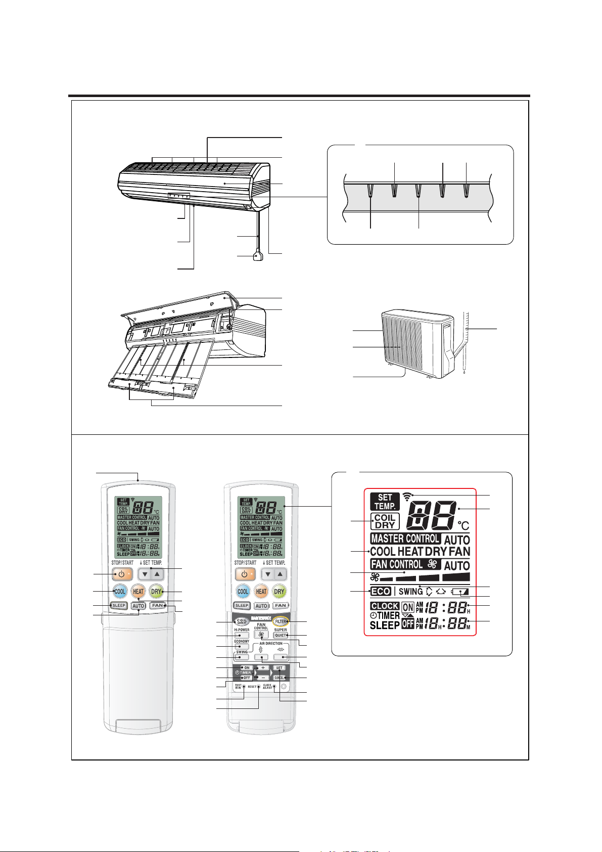
This figure shows the control display when all indicator lamps are on. It may differ from the actual display.
Z
\
]
b
c
e
h
i
l
m
n
q
r
d
f
g
j
k
p
s
o
Q
R
3
S
T
U
V
W
X
Page 5
NAME OF PARTS
Fig. 1 Indoor Unit
1 Intake Grilles
2 UV Lamp (4 position)
3 Indicator (Fig. 2)
4 MAINTENANCE SIGN Indicator Lamp (red)
5 TIMER Indicator Lamp (green)
If the TIMER indicator lamp flashes when the
●
timer is operating, it indicates that a fault has
occurred with the timer setting (See Page 24
Auto Restart).
6 OPERATION Indicator Lamp (red)
7 SUPER QUIET Indicator Lamp (green)
8 HI-POWER Indicator Lamp (orange)
9 Remote Control Signal Receiver
0 Open Panel (Fig.3)
A MAINTENANCE/MANUAL AUTO button
●
When kept on pressing the MANUAL AUTO
button for more than 10 seconds, the forced
cooling operation will start.
● The forced cooling operation is used at the
time of installation.
Only for authorized service personnel's use.
● When the forced cooling operation starts by
any chance, press the START/STOP button
to stop the operation.
B Air Filter
C Dust Box
D Air Flow Direction Louver
E Right-Left Louver
(behind Air Flow Direction Louver)
F Power Diffuser
G Power Supply Cord
H Power Supply Plug
Fig. 4 Outdoor Unit
I Intake Port
J Outlet Port
K Pipe Unit
L Drain Port (bottom)
Fig. 5 Remote Control Unit
M Signal Transmitter
N Remote Control Unit Display (Fig. 6)
O COIL DRY Display
P Operating Mode Display
Q FAN CONTROL Display
R ECONOMY Operation
S Transmit Indicator
T Temperature Display
U SWING Display
V Battery Indicator Display
W ON TIMER Display
X OFF TIMER Display
Y START/STOP button
Z SET TEMP. button (
[ COOL button
\ DRY button
] HEAT button
` SLEEP button
a AUTO button
b FAN button
c COIL DRY button
d FILTER button
e HI-POWER button
f SUPER QUIET button
g FAN CONTROL button
h ECONOMY button
i SWING button
j AIR DIRECTION (Left-Right) button
k AIR DIRECTION (Up-Down) button
l ON TIMER button
m OFF TIMER button
n SET TIME buttons (
o SET (TIMER) button
p CANCEL (TIMER) button
q TEST RUN button
r RESET button
s CLOCK ADJUST button
/ )
/ )
4
Page 6
PREPARATION
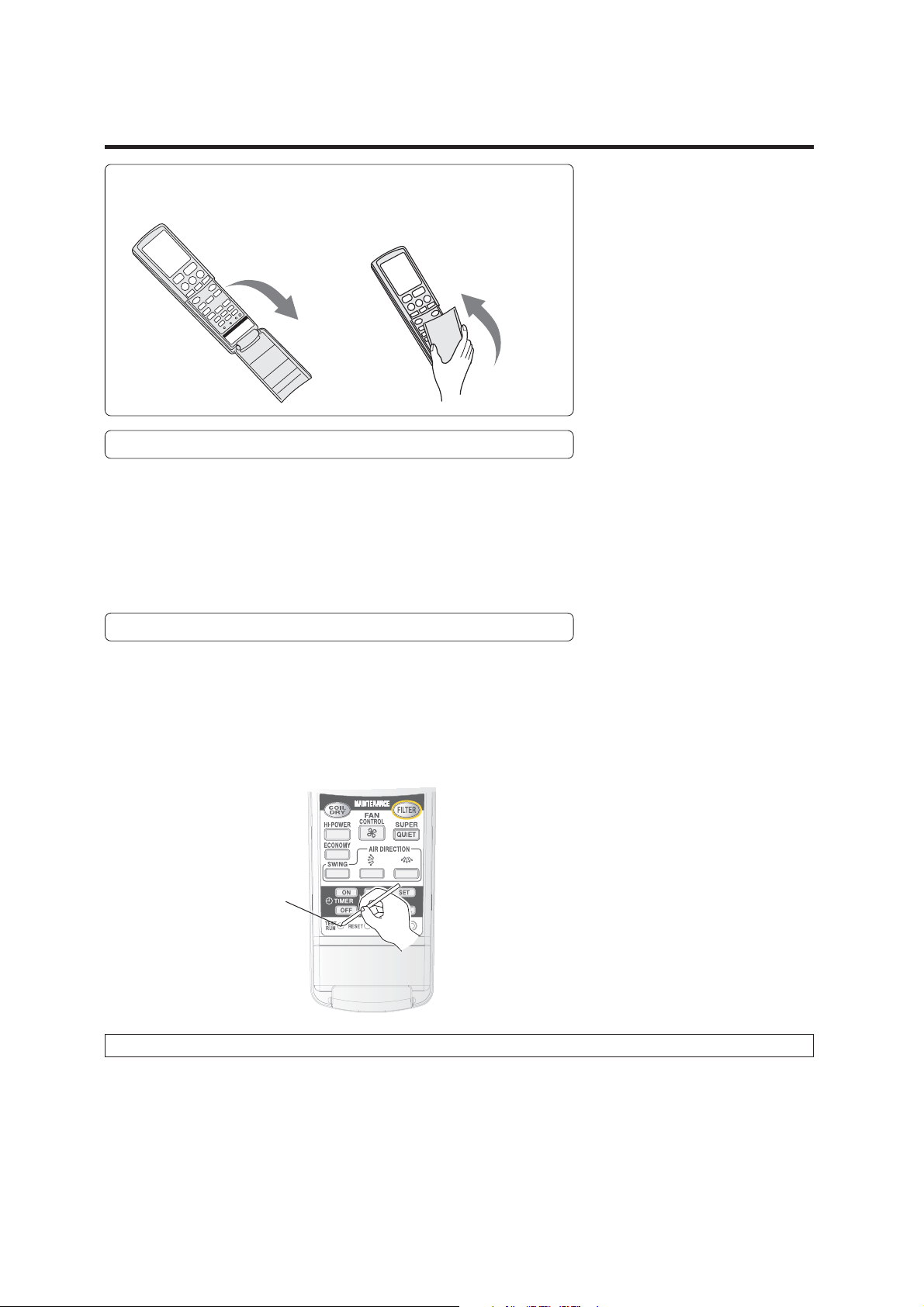
How to open and close the remote control's cover.
Open gently (do not be
too rough).
Take hold of both sides
of the cover, and insert
the cover into its place
until you hear a click.
Prompts to change remote control's batteries
● Remote control periodically starts and stops.
Battery Indicator Display (Fig.6 V) shown during operations.
• At start-up: blinks 5 times
• At shut-down: remains lit for about 10 minutes.
If the Battery Indicator Display is shown, please change your batteries as soon as
possible, even if your remote control is still usable.
About the TEST RUN button
● This button is used when installing the air conditioner and should not be used
under normal conditions, as it will cause the air conditioner’s thermostat function to operate incorrectly.
● If this button is press during normal operation, the unit will switch to the test
operation mode and the OPERATION Indicator Lamp (red) (Fig.2 6) and TIMER
Indicator Lamp (green) (Fig.2 5) on the Indoor Unit will flash simultaneously.
● To the stop the test operation mode, press the START/STOP button (Fig.5 Y) to
stop the air conditioner.
TEST RUN button
About the Compulsory Cooling Mode
● If the TEST RUN button (Fig.5 q) is pressed during the cooling mode, the unit will change to the compulsory cooling mode
and the room will be cooled regardless of the thermostat setting.
● Use the compulsory cooling mode to collect refrigerant in the outdoor unit before moving the air conditioner. (Do not use
this button under normal conditions.)
5
Page 7
Turn on the Power
Connect the Power Supply Plug (Fig. 1 H) to an electrical outlet;
in the case of a direct line connection, turn on the circuit breaker.
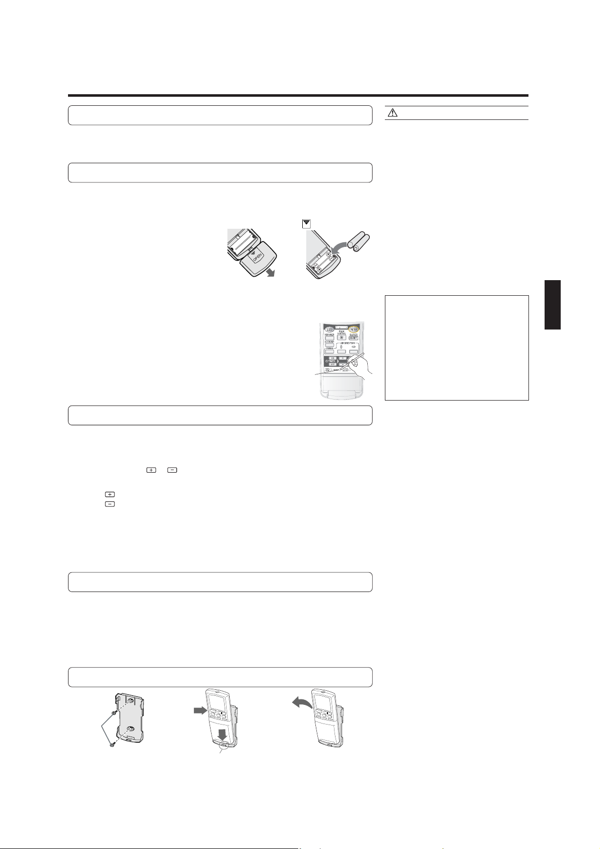
Load Batteries (LR03
××
× 2)
××
Press and slide the battery compartment lid on the re-
1
verse side to open it.
Slide in the direction of the arrow while pressing the mark.
Insert batteries.
2
Be sure to align the battery polarities (+/-) correctly.
Close the battery compartment lid.
3
About the RESET (Fig.5 r) button
4
• If the remote control is unable to function
normally after the batteries are changed,
please press the RESET button (Fig.5 r).
• Press the RESET button (Fig.5 r) using a
ball-point pen or other such items with a
relatively sharp tip.
RESET
botton
CAUTION!
● Take care to prevent infants from
accidentally swallowing batteries.
● When not using the Remote Control Unit
for an extended period, remove the
batteries to avoid possible leakage and
damage to the unit.
● If leaking battery fluid comes in contact
with your skin, eyes, or mouth, immediately wash with copious amounts of
water, and consult your physician.
● Dead batteries should be removed
quickly and disposed of properly, either
by placing in a public battery collection
receptacle, or by returning to appropriate
authority.
● Do not attempt to recharge dry batteries.
● Please always press the RESET button
after changing batteries to avoid the
possibility of functional errors.
Never mix new and used batteries, or
batteries of different types.
Batteries should last about one year
under normal use.
In any of the following situations, please
change your batteries.
• The Battery Indicator Display is shown
• No data transmission possible unless
close to Indoor Unit
• The Remote Control Unit is unable
to work properly
Set the Current Time
Press the CLOCK ADJUST button (Fig. 5 s)
1
Use the tip of a ball-point pen or other small object to press the button.
Use the / SET TIME buttons (Fig. 5 n)to adjust
2
the clock to the current time.
button: Press to advance the time.
button: Press to reverse the time.
(Each time the buttons are pressed,the time will be advanced/reversed in
one-minute steps.hold the buttons depressed to change the time quickly
in ten-minute steps.)
Press the SET button (Fig. 5 o).
3
This completes the time setting and starts the clock.
To Use the Remote Control Unit
● The Remote Control Unit must be pointed at signal receiver (Fig. 1 9) to operate
correctly.
● Operating Range: About 7 meters.
● When a signal is properly received by the air conditioner, a beeping sound will
be heard.
● If no beep is heard, press the Remote Control Unit button again.
Remote Control Unit Holder
Insert
Screws
Press in
Pull out
1Mount the Holder. 2Set the Romote Control
Unit.
3To remove the Remote Con-
trol Unit (when use hand).
6
Page 8

OPERATION
To Select Mode Operation
Press the necessary Operation button.
Cooling Operation: Press the COOL button (Fig.5 [)
Heating Operation: Press the HEAT button (Fig.5 ])
Dry Operation : Press the DRY button (Fig.5 \)
Auto Operation : Press the AUTO button (Fig.5 a)
Fan Operation : Press the FAN button (Fig.5 b)
The Indoor Unit's OPERATION Indicator Lamp (red) (Fig.2 6) will light.
The Air conditioner will start operating.
Pressing the unit's START/ STOP button (Fig.5 Y) will run the unit in its most
recently-used mode.
To Set the Thermostat
Press the SET TEMP. button (Fig. 5 Z).
: Press to raise the thermostat setting.
: Press to lower the thermostat setting.
●Thermostat setting range:
Cooling/Dry ........................ 18 to 30 °C
Heating ............................... 16 to 30 °C
AUTO .................................. 18 to 30 °C
The thermostat can not be used to set room temperature during the FAN Mode (the
temperature will not appear on the Remote Control Unit’s Display).
To Set the Fan Speed
Press the FAN CONTROL button (Fig. 5 g).
Each time the button is pressed, the fan speed changes in the following order:
AUTO
About three seconds later, the entire display will reappear.
When set to AUTO:
Cooling : As the room temperature approaches that of the thermostat setting,
the fan speed becomes slower.
Heating : Fan operates so as to optimally circulate warmed air.
However, the fan will operate at very low speed when the temperature of the air issued from the indoor unit is low.
Fan : The fan operates at the low speed.
Example: When set to COOL
Example: When set to 28°C
Super Quiet Operation:
Press the SUPER QUIET button(Fig.5 f).
The Indoor Unit's SUPER QUIET Indicator Lamp (green) (Fig.2 7) will light. (No
display on the Remote Control Unit)
SUPER QUIET operation begins.
The Indoor Unit's airflow will be reduced for quieter operation.
● In SUPER QUIET mode, any of the changes listed below will switch SUPER QUIET
Operations off.
• Changing the Fan Speed.
• Switching to HI-POWER Operation.
● When the Air Conditioner's operations are stopped, SUPER QUIET Operation is
cancelled. When the unit is started again, it will run at the Fan Speed displayed
on the Remote Control Unit's FAN CONTROL Display.
● During SUPER QUIET Operation, Heating and Cooling and Dry performance will
be reduced somewhat.
7
Page 9

To Stop Operation
Press the START/STOP button (Fig.5 Y).
The OPERATION Indicator Lamp (red) (Fig. 2 6) will go out.
About AUTO CHANGEOVER Operation
AUTO: ● When AUTO CHANGEOVER operation first selected, the fan will oper-
ate at very low speed for about one minute, during which time the unit
detects the room conditions and selects the proper operating mode.
If the differance between thermostat setting and actual room temperature is more than +2 °C → Cooling or dry operation
If the difference between thermostat setting and actual room temperature is within ±2 °C → Monitor operation
If the difference between thermostat setting and actual room temperature is more than –2 °C → Heating operation
● When the air conditioner has adjusted your room’s temperature to near
the thermostat setting, it will begin monitor operation. In the monitor
operation mode, the fan will operate at low speed. If the room temperature subsequently changes, the air conditioner will once again
select the appropriate operation (Heating, Cooling) to adjust the temperature to the value set in the thermostat.
(The monitor operation range is ±2 °C relative to the thermostat setting.)
● If the mode automatically selected by the unit is not what you wish,
select one of the mode operation (HEAT, COOL, DRY, FAN).
About Mode Operation
Heating: ● Use to warm your room.
● When Heating mode is selected, the air conditioner will operate at very
low fan speed for about 3 to 5 minutes, after which it will switch to the
selected fan setting. This period of time is provided to allow the indoor
unit to warm up before begin full operation.
● When the room temperature is very low, frost may form on the outside
unit, and its performance may be reduced. In order to remove such
frost, the unit will automatically enter the defrost cycle from time to
time. During Automatic Defrosting operation, the OPERATION Indicator Lamp (red) will flash, and the heat operation will be interrupted.
Cooling: ● Use to cool your room.
Dry: ● Use for gently cooling while dehumidifying your room.
● You cannot heat the room during Dry mode.
● During Dry mode, the unit will operate at low speed; in order to adjust
room humidity, the Indoor Unit’s fan may stop from time to time. Also,
the fan may operate at very low speed when adjusting room humidity.
Fan: ● Use to circulate the air throughout your room.
During Heating mode:
Set the thermostat to a temperature setting that is higher than the current room
temperature. The Heating mode will not
operate if the thermostat is set lower than
the actual room temperature.
During Cooling/Dry mode:
Set the thermostat to a temperature setting that is lower than the current room
temperature. The Cooling and Dry modes
will not operate if the thermostat is set
higher than the actual room temperature
(in Cooling mode, the fan alone will operate).
During Fan mode:
You can not use the unit to heat and cool
your room.
8
Page 10

ADJUSTING THE DIRECTION OF AIR CIRCULATION
● Adjust the up, down, left, and right air directions with the AIR DIRECTION buttons on the Remote Control Unit.
● Use the AIR DIRECTION buttons after the Indoor Unit has started operating and the airflow-direction louvers have
stopped moving.
R
Vertical Air Direction Adjustment
Open the lid on the Remote Control Unit.
Press the AIR DIRECTION (Up-Down) button. (Fig. 5 k)
● When the AIR DIRECTION (Up-Down) button (Fig.5 k) is pushed, the airflow
direction changes within the range to the following.
●
You can select the desired airflow direction.
Cooling/Dry range1234 Heating range5678
1
2
Air flow-direction
louvers
Power diffuser
* The Remote Control Unit
display does not change.
3
4
* The up/down airflow-direction louvers move in the
direction of the arrow from the closed position.
●
In order to maximize the heating and cooling
performance, use the ranges above.
Fan range 12345678
5
6
7
8
DANGER!
● Never place fingers or foreign objects inside the outlet ports, since the internal fan
operates at high speed and could cause
personal injury.
About airflow direction adjustments
●
When the unit is turned on or the op-
eration mode is changed, the position
of the airflow-direction louvers is automatically set as listed below to match
the operation mode (heating, cooling,
etc.) selected.
Cooling/Dry/Fan: 1 horizontal airflow
Heating: 7 downward airflow
● During HI-POWER operation (see page
12), the up/down airflow direction is set
automatically to optimize the heating
and cooling performance.
● When the AIR DIRECTION buttons on
the Remote Control Unit are pressed,
it may take a short time for the up/
down airflow-direction louvers or the
left/right airflow-direction louvers to
reach the desired position.
During that time, the airflow direction
cannot be adjusted even if the AIR DIRECTION buttons are repeatedly
pressed.
● During the monitor period in the auto
mode (see page 7), horizontal airflow
direction is set and cannot be adjusted.
● If the AIR DIRTCTION (Up-Down) button is pressed during the up/down
swing operation (see page 11), the up/
down swing operation will stop. In
addition, if the AIR DIRECTION (LeftRight) button is pressed during the left/
right swing operation, the left/right
swing operation will stop.
Right-Left Adjustment
Open the lid on the Remote Control Unit.
Push the AIR DIRECTION (Left-Right) button (Fig.5 j).
● When the AIR DIRECTION (Left-Right) button (Fig.5 j) is pushed, the airflow
direction will change in the following order.
ss
Front airflow
Left airflow
t
Right airflow
Front airflow
t
● You can select the desired airflow direction.
● The Indoor Unit is set for front airflow when the unit
is turned on.
* The Remote Control Unit
display does not change.
9
Page 11

SWING OPERATION
Begin air conditioner operation before performing this procedure.
To select SWING Operation
Open the Remote Control Unit lid to perform swing operation
settings.
Press the SWING button (Fig. 5 i).
The SWING Display (Fig. 6 U) will light.
Each time the SWING button is pressed, the swing operation will change in the
following order.
Up/down swing operation Left/right swing operation
Swing operation stops Up/down/left/right swing operation
To stop SWING Operation
Press the SWING button (Fig.5 i) and select STOP.
Airflow direction will return to the setting before swing was begun.
About Swing Operation
● Up/down swing: Swing operation begins using the
following range according to the current airflow direction.
Airflow direction is 1–4 (for cooling, dry, fan).
With the upper airflow-direction louver in the
horizontal position, the lower airflow-direction
louver moves (swings) to direct airflow to a wide
area.
Airflow direction is 5–8 (for heating, fan).
With the airflow-direction louvers set for downward or straight down airflow, airflow is directly
mainly at the floor.
● Left/right swing: The airflow-direction louvers move
(swing) in the left/right airflow direction.
● Up/down/left/right swing: The airflow-direction louvers
move (swing) in both the up/down and left/right airflow
directions.
●
The SWING operation may stop temporarily when the
air conditioner’s fan is not operating, or when operating
at very low speeds.
●
If the AIR DIRECTION (Up-Down) button is pressed
during the up/down swing operation, the up/down
swing operation will stop and if the AIR DIRECTION
(Left-Right) button is pressed during the left/right swing
operation, the left/right swing operation will stop.
10
Page 12

TIMER OPERATION
Before using the timer function,be sure that the Remote Control Unit is set to the correct current time (See page 6).
To Use the OFF TIMER or ON TIMER
Open the Remote Control Unit lid to perform the timer function settings.
Press the desired Operation button or START/STOP
1
button (Fig. 5 Y).
(if the unit is already operating, proceed to step 2).
The Indoor Unit’s OPERATION Indicator Lamp (red) (Fig. 2 6) will light.
Select the desired timer operation time, and then press
2
the OFF TIMER button (Fig. 5 m) or the ON TIMER button (Fig. 5 l).
The OFF or ON timer indicator flashes.
Use the SET TIME buttons (Fig. 5 n) to adjust the de-
3
sired OFF time or ON time.
Button: Press to advance the time.The time advances in 5-minutes
Button: Press to reverse the time.The time goes backward in 5-minute
increments.
increments.
Point the Remote Control Unit towards the Indoor Unit
4
and press the SET button (Fig. 5 o).
The OFF or ON timer Indicator stops flashing.
The TIMER Indicator Lamp (green) (Fig.2 5)on the Indoor Unit will light.
If the ON TIMER function is selected, the air conditioner operation stops.
To Use the Program timer
Press the START/STOP button (Fig. 5 Y)
1
(if the unit is already operating, proceed to step 2).
The Indoor Unit’s OPERATION Indicator Lamp (red) (Fig. 2 6) will light.
Set the desired times for OFF timer and ON timer.
2
See the section “To Use the OFF timer or ON timer” to set the desired
mode and times.
The indoor unit’s TIMER Indicator Lamp (green) (Fig.2 5) will light.
To Cancel the Timer
Press the CANCEL button.
To Change the Timer Settings
Perform operations 2–4.
To Stop Air Conditioner Operation
while the Timer is Operating
Press the START/STOP button.
To Cancel the Timer
Press the CANCEL button.
TIMER Indicator Lamp (green) will go
out.Canceling the OFF TIMER or the ON
TIMER
1. Press the TIMER button of the function to
cancel (OFF or ON).
2. Press the CANCEL button.
To Change the Timer Settings
1. Press the TIMER button of the function
to change (OFF or ON).
2. Set the timer using the “
TIMER buttons.
3. Press the SET button.
To Stop Air Conditioner Operation
while the Timer is Operating
Press the START/STOP button.
” and “ ”
About the Program timer
● The PROGRAM timer allows you to integrate OFF timer and ON timer operations
in a single sequence. The sequence can involve one transition from OFF timer to
ON timer,or from ON timer to OFF timer,within a twenty-four hour period.
● The first timer function to operate will be the one set nearest to the current
time.The order of operation is indicated by the arrow in the Remote Control
Unit’s display (OFF → ON,or OFF ← ON).
● One example of PROGRAM timer use might be to have the air conditioner automatically stop (OFF timer)after you go to sleep,then start (ON timer)automatically
in the morning before you arise.
11
Page 13

SLEEP TIMER OPERATION
Unlike other timer functions, the SLEEP timer is used to set the length of time until air conditioner operate is stopped.
To Use the SLEEP timer
While the air conditioner is operating or stopped, press the
SLEEP button (Fig. 5 `).
Each time the button is presssd, the time changes in the following order:
→ 1.0 → 2.0 → 3.0 → 5.0 → 7.0 → 9.0(hour)
(RESET)
The Indoor Unit’s OPERATION Indicator Lamp (red) (Fig. 2 6) and the TIMER Indicator Lamp (green) (Fig. 2 5) light.
To Change the Timer Settings
Press the SLEEP button (Fig.5 `) once to display the last setting time.
Press the SLEEP button (Fig.5 `) again to change the time.
Each time the button is pressed, the time changes in the following order (Change
from the last setting time):
→ 1.0 → 2.0 → 3.0 → 5.0 → 7.0 → 9.0(hour)
(RESET)
Confirmation of TIMER's time
To Cancel the Timer:
Press the CANCEL (TIMER) button.
To Stop the Air Conditioner During Timer
Operation:
Press the START/STOP button.
The left time of the TIMER which is being set currently will be displayed for 5 minutes.
12
Page 14

ECONOMY OPERATION
Begin Air Conditioner operation before performing this procedure.
Open the Remote Control Unit lid.
To Use the ECONOMY Operation
Press the ECONOMY button (Fig.5 h).
"ECO" appears on the Remote Control Unit display.
Economy operation begins.
To Stop the ECONOMY Operation
Press the ECONOMY button (Fig.5 h) again.
"ECO" disappears from the Remote Control Unit display.
Normal operation begins.
About ECONOMY Operation
At the maximum output, ECONOMY Operation is approximately 70% of normal air conditioner operation for cooling and
heating.
When ECONOMY operation is performed during the cooling mode, dehumidification is improved. This function is especially
convenient when you want to remove the humidity in the room without significantly lowering the room temperature.
During ECONOMY operation, the thermostat setting automatically changes according to the temperature to avoid Unnecessary cooling and heating for the most economical operation.
● If the room is not cooled(or heated) well during economy operation, select normal operation.
● Once air conditioner operation is stopped, normal operation begins when the indoor unit is turned on again.
● During the monitor period in the AUTO mode, the air conditioner operation will not change to ECONOMY operation even if
ECONOMY operation is selected by pressing the ECONOMY operation button.
HI-POWER OPERATION
Begin Air Conditioner operation before performing this procedure.
Open the Remote Control Unit lid.
To Use the HI-POWER Operation
Press the HI-POWER button(Fig.5 e).
The Indoor Unit's HI-POWER Indicator Lamp (orange) (Fig.2 8) will light.
HI-POWER operation begins.
To Stop the HI-POWER Operation
Press the HI-POWER button(Fig.5 e) again.
The Indoor Unit's HI-POWER Indicator Lamp(orange) (Fig.2 8) will go out.
Normal operation begins.
However, HI-POWER operation will automatically stop under the following conditions.
● If SUPER QUIET Operations are selected during HI-POWER Operation, HI-POWER will be cancelled.
● During cooling mode
The room temperature is 1°C below the thermostat setting or 30 minutes has passed since the HI-POWER operation began.
● During heating mode
The room temperature is 2°C above the thermostat setting.
● During fan mode
15 minutes has passed since the HI-POWER operation began.
About HI-POWER Operation
● During cooling mode
The Indoor unit will operate at maximum power until the room temperature is 1°C below the thermostat setting.
● During heating mode
The Indoor unit will operate at maximum power until the room temperature is 2°C above the thermostat setting.
● During dry mode
The airflow can not be set during HI-POWER operation
● During fan mode
The airflow from the Indoor Unit is increased.
13
Page 15

COIL DRY OPERATION
● After allowing the interior of the indoor unit time to dry, run the UV filter clean, to limit mold and bacteria on the interior of
the unit and on the air filter. This function shows clear results after cooling or dehumidifying.
● For COLID DRY Operation, press the COIL DRY button. Cleaning operations will run for about 20 minutes and stop automati-
cally.
To start COIL DRY Operation
Press the COIL DRY button (Fig.5 c) (when the air conditioner
is operating or stopped).
Only the OPERATION Indicator Lamp (red) (Fig2. 6)on the Indoor Unit will light.
“COIL DRY” appears on the Remote Control Unit display and disappears after approximately 20 minutes.
If the COIL DRY button (Fig5. c) is pressed again during COIL DRY operation, COIL
DRY operation will start again.
To stop COIL DRY Operation
Press the START/STOP button (Fig.5 Y) during COIL DRY op-
eration.
The OPERATION Indicator Lamp (red) (Fig2. 6)on the Indoor Unit will go out.
● The Remote Control Unit will be in the operation-stopped condition.
About COIL DRY Operation
The following procedures are performed during COIL DRY operation before the
operation automatically stops after approximately 20 minutes.
1 Drying
After about 18 minutes of COIL DRY Operation, drying shall be performed on the
interior of the indoor unit. All dirt and foul odors are to be removed from the air
filter.
2 UV filter cleaning (about 2 minutes)
UV rays are discharged onto the air filter, so that all dirt, odor, and dust undergo
disinfecting and deodorizing processing, and are recycled into the dust box. At
the same time, the air filter's disinfecting and deodorizing functions are reset,
and returned to cleaning mode.
3 Operations stop
The COIL DRY operation come to an end.
NOTE!
● When COIL DRY operation begins, the
Indoor Unit operates in the heating
mode and the fan mode to dry the inside
of the Indoor Unit. As a result, the room
temperature and humidity may rise
slightly.
● COIL DRY operation cannot be used to
clean the air in the room.
● COIL DRY operation is most effective
when performed frequently.
14
Page 16

AUTO FILTER MAINTENANCE FUNCTION
● This is a convenient function that automatically removes dust from the air filters after a set amount of time of air conditioner
operation.
● The auto filter maintenance function can also be started using the remote control unit.
Auto Filter Maintenance
About operating the Auto Filter Maintenance
● Auto filter maintenance is performed after the air conditioner operates for a set
amount of time and is stopped or the FILTER button (Fig.5 d) on the Remote
Control Unit is pressed.
● During auto filter maintenance, the MAINTENANCE SIGN Indicator Lamp (red)
(Fig.2 4) on the Indoor Unit will light.
1. Air filters come out
● The air filters automatically come out of the indoor unit under the open panel. At
this time, the dust on the air filters is collected in the dust boxes (behind the open
panel).
Open panel
2. Air filter retract
● After the air filters come out, they automatically retract to their original positions
in the Indoor Unit.
CAUTION!
Do not touch the air filters during the auto
filter maintenance.
● The Indoor Unit may malfunction if the
air filters are pulled or pushed.
● If the air filters are unnecessarily pulled,
they may be damaged or fall and cause
personal injury.
● When the auto filter maintenance is complete, the MAINTENANCE SIGN Indica-
tor Lamp (red) (Fig.2 4) on the Indoor Unit goes out.
MAINTENANCE SIGN Indicator Lamp(red) flashes
The MAINTENANCE SIGN Indicator Lamp (red) (Fig.2 4) will flash during auto filter
maintenance if the air filters are not Installed or are pulled. If this occurs during air
conditioner operation, unplug the power supply cord from the Electrical outlet and
follow procedures "Dust Box Maintenance" to install the air filters.
Changing the FILTER MAINTENANCE Interval
The filter maintenance interval can be changed.
Some dust may be tough to clear away with Auto Filter Maintenance.
In such a situation, please switch the Interval to 50H for more thorough cleaning.
While cleaning, please place the remote control in stop mode (so that only the CLOCK
and the time are displayed).
1. Hold down the SET TIME button (Fig.5 n) for at least 3 seconds.
Switches from displaying the current time to displaying the interval, and begins
blinking.
2. Set the interval using the SET TIME button's
Pressing these buttons will allow you to scroll between the figures below.
50H
100H
Factory settings are 100H.
For more detailed FILTER MAINTENANCE, set to 50H.
3. Point the remote control to the main unit and press the SET button (Fig.5 o).
The display will stop blinking and send signals to the Indoor Unit.
If you do not press the SET button (Fig.5 o), there is no way to save the work
time settings.
and keys (Fig.5 n).
15
Page 17

About the Auto Filter Maintenance function
● Depending on how dirty the air filters are, all of the dust may not be removed
from the air filters during the auto filter maintenance. In this case, perform
auto filter maintenance again.
● If dust remains on the air filters after auto filter maintenance has been performed a number of times, perform dust box maintenance (see page 17)
● Depending on the condition of the dust on the air filters, such as if the dust is
particularly oily or hardened, the dust may not be removed during the auto
FILTER MAINTENANCE. In this case, remove the air filters and clean with water
(see page 20).
● During auto filter maintenance, clicking or hissing sounds may be producd.
● During FILTER MAINTENANCE, if you pull or push the filter upwards, the
FILTER MAINTENANCE process will stop and the MAINTENANCE SIGN Indicator Lamp (red) (Fig.2 4) will blink.
At this time, please refer to Dust Box Maintenance, FILTER Installation.
● If the FILTER is inserted too low, it will automatically correct itself by moving
upwards.
● If there are any objects located under the indoor unit, should the FILTER fall
out, it would hit these objects and would no longer be able to work properly.
AUTO Filter Maintenance using the Remote Control Unit
Press the FILTER btton(Fig.5 d)
(When the Air Conditioner is operating or stopped.)
The MAINTENANCE SIGN Indicator Lamp (red) (Fig.2 4) on the Indor Unit will light.
Auto filter maintenance begins.
● If the FILTER button is pressed during Air Conditioner operation, the Air Conditioner will stop, auto filter maintenance will be perfomed, and the air conditioner
will start operating again after the auto filter maintenance is complete.
● Even if the FILTER button is pressed during the auto filter maintenance, the cleaning will not stop.
About the notification for Dust Box cleaning
● When auto filter maintenance is not activated, but the Indoor Unit's MAINTENANCE SIGN Indicator Lamp (red) (Fig.2 4) is illuminated, this means that it is
time to perform dust box cleaning. In such a situation, please clean your dust
box.
● Due to differences in Auto Filter Maintenance intervals, there are also differences
in the amount of time that an air conditioner runs before its MAINTENANCE
SIGN Indicator Lamp (red) (Fig.2 4) is lit.
Auto filter maintenance interval Interval before maintenance sign
50 hours 2000 hours
100 hours 4000 hours
● While the MAINTENANCE SIGN Indicator Lamp (red) is illuminated, Auto Filter
Maintenance will not work. (Even if you press the Remote Control Unit's FILTER
button, it will not run). In such a situation, please clean the DUST BOX, and press
the MAINTENANCE/ MANUAL AUTO button (Fig.3 A) . The MAINTENANCE SIGN
Indicator Lamp (red) (Fig.2 4) will go out.
● The MAINTENANCE SIGN Indicator Lamp (red) will only light up when the Air
Conditioner is running or coming to a halt.
● If you put out the MAINTENANCE SIGN Indicator Lamp (red) (Fig.2 4) without
cleaning the Dust Box, the next time that Auto Filter Maintenance runs, dust may
spill out from the unit. When the MAINTENANCE SIGN Indicator Lamp (red) (Fig.2
4) is illuminated, please be sure to clean the Dust Box.
indicator lamp (red) is illuminated
16
Page 18

PERFORMING MAINTENANCE
● Frequent maintenance will extend the life of the air conditioner and improve the cooling and heating performance.
● Before maintenance, stop air conditioner operation using the remote control and unplug the power supply cord from the
electrical outlet.
CAUTION!
Before cleaning the air conditioner, be sure to turn it off
and unplug the power supply cord from the electrical
outlet.
The internal fan operates at high speed and could cause
personal injury.
When removing the dust boxes and grill, do not touch any
metal parts (heat exchanger, etc.).
Personal injury may result.
When cleaning the air conditioner, do not stand on any
unstable objects.
You might fall and personal injury could result.
When cleaning the dust boxes and grill, be sure to install
them securely.
If the dust boxes and grill are not properly installed,
they could fall and cause personal injury.
Dust Box Maintenance
● If the MAINTENANCE SIGN Indicator Lamp (red) (Fig.2 4) on the Indoor
Unit is lit, be sure to clean the dust boxes. If the Indoor Unit is installed in
an area with a lot of dust, clean the dust boxes every 3 months even if the
MAINTENANCE SIGN Indicator Lamp (red) (Fig.2 4) is not lit.
● When cleaning the dust boxes, dust may fall to the floor. Lay newspaper,
etc. under the Indoor Unit before cleaning the dust boxes.
MAINTENANCE SIGN
TIMER OPERATION HI-POWER
1. Remove the dust boxes and air filters from the indoor unit. Remove the air filters
from the dust boxes.
Preparation
1. Open the open panel.
● Stop the air conditioner using the Remote Control Unit.
● Unplug the power supply cord from the electrical outlet.
Open panel
3. Remove the dust boxes and air filters.
Grab the center of each dust box, lift the bottom in direction 1, and then remove the dust box in direction 2.
(Remove the dust boxes and air filters together.)
SUPER QUIET
Grab both sides of the open panel and fully open the
open panel. Continue to open the open panel past the
horizontal position. (The panel will remain open even
after it is released.)
2. Remove the dust box's lock.
Dust boxes
Latches
“Click”
“Click”
Move the holding positions (yellow) on either side of the
dust boxes (2 on the left and right) inwards, and remove
the lock.
17
1
2
4. Remove the air filter from each dust box.
Grab the holding position on the air filter and pull the air
filter out from the dust box in the direction of the arrow.
Air filter
Holding
position
Dust box
● When the air filter is removed from the dust box, dust
may fall from the dust box. Lay newspaper, etc. under
the dust box before removing the air filter.
Page 19

2. Remove the dust collected in the dust boxes and clean the dust boxes.
1. Open the dust boxes.
1 Hold the latch (light blue) on both sides of the interior
of the dust box, and pull outwards until you hear a
"catch" sound.
Latch
"Click"
2 Open the interior of the box.
Inner case
Outer case
● Be gentle when opening, as excess force may result in
damage and malfunction.
● When opening the inner case, dust collected inside the
dust box may fall out. During this process, please place
newspapers or some other cover under the dust box.
3 Cleaning the interior of the box.
• Use a vacuum to clean up the dust on the brush and
the box, or use a brush to wipe this dust away.
Outer case
Brush holder
"Click"
● After washing with water, make sure the dust boxes are
completely dry before installation. The brushes are especially difficult to dry so wipe them with a towel, etc. to
make sure they are completely dry. If the dust boxes are
installed wet, the dust may not be removed from the air
filters during auto filter maintenance.
3. Dust box installation
1 First pull down on the outer casing, and then cover up
the inner casing.
Inner case
Outer case
2 Put the latches (light blue) on either side into their
place.
"Click"
● When installing the dust box, please insert the latch directly into its correct position. If the latch is not fully in
place, and the box is installed onto the main unit, Auto
Filter Maintenance will not work.
"Click"
latch
Inner case
Brush
● Do not be too forceful when opening up the brush holder.
Otherwise, this may result in damage and malfunction.
2. Wash the front and rear cases with water
if they are extremely dirty.
1 Lightly rub the brushes clean with 40°C–45°C hot wa-
ter. If the brushes are difficult to clean, apply a mild
synthetic laundry detergent (low or neutral alkalinity)
and rub lightly.
2 Rub the front and rear cases lightly with a sponge.
3 Rinse under running water.
4 Remove the water from the front and rear cases.
5 Wipe the brushes and cases with a towel, etc., and
place in a shaded area to dry.
● Do not use a cleaner other than a mild synthetic laundry
detergent (low or neutral alkalinity).
● Do not clean with hot water above 60°C.
● Do not clean with any abrasive or hard object.
● Do not dry with hot air from a hair dryer, etc.The cases
may be deformed and the brushes may come off.
18
Page 20

3.
Install the dust box onto the main unit, press the "MAINTENANCE / MANUAL AUTO" button, and then insert the air filter.
1.
Install the dust box onto the main unit.
1 Make sure that the dust box's 2 yellow latches are
open.
2 Open the front panel and insert the dust box into the
unit until you hear it catch in place.
"Beep"
*If the MAINTENANCE SIGN Indicator Lamp (red) (Fig.2
4) light is illuminated, it will go out at this point.
Latch
● Press down on the MAINTENANCE / MANUAL AUTO
button, and release the button when you hear a "beep."
If the MAINTENANCE / MANUAL AUTO button is held
down for more than 3 seconds, MANUAL AUTO Opera-
Remove
Lock
tion will begin (page 22).
● Please be sure to press the MAINTENANCE / MANUAL
AUTO button. Auto Filter Maintenance is unable to be
performed when the MAINTENANCE SIGN Indicator
Lamp (red) (Fig.2 4) is illuminated.
3 Insert the dust box fully and move the two latches on
either side outside to lock it in place.
3. Insert the air filters into the unit (one on
both the left and right side).
1 Insert the air filter net into the dust box slot.
Latch
Remove
"click"
Lock
● If the latches are locked while installing the dust box,
malfunctions may result and the dust box may fall out.
● During installation, make sure that you have a good
grip of the middle of the dust box and insert it soundly
in its place. Should there be any errors in installation,
the dust box may fall out and cause injury.
2. Insert the power supply line into its socket
and press the MAINTENANCE / MANUAL
AUTO button (Fig.3 A).
1 Insert the power supply line into its socket.
2 Press the unit's "MAINTENANCE / MANUAL AUTO"
button.
19
Dust Box
INLET
Direc
t
i
o
n
Air filter
2 Insert the air filter until it reaches the upper limits of
the air filter frame (on both sides). (After about 2 seconds, the air filter will automatically lock into its place).
Dust box
Mark
Air filter
Air filter
frame
Page 21

PERFORMING MAINTENANCE (CONTINUED)
3. Install the dust box onto the main unit, press the "MAINTENANCE / MANUAL AUTO" button, and then insert the air filter. (Continued)
3 Following the same procedure, insert the other side's
air filter.
● During installation, please make sure that both the filter
and your hands are dry. Any moisture on the filter or
on your hands may result in malfunctions or electric
shock.
● Please insert the air filter correctly according to the
designated direction. Incorrect insertion may result in
excess noise or functional problems.
● Insert the air filter to the point designated on the filter.
If the filter is not in the correct position, it may not
automatically lock into its place.
4. Close the Front Panel.
Air Filter Maintenance
● Wash the air filters with water if small dust particles remain on the air filters even after auto filter maintenance is performed.
● It is recommended to perform dust box maintenance when the air filter maintenance is performed.
1. Open the open panel, and then remove
the dust boxes and air filters.
Refer to procedure 1 in Dust Box Maintenance (see page
17).
2. Remove the air filters from the dust boxes.
Refer to procedure 1 in Dust Box Maintenance (see page
17).
3. Remove the dust with a vacuum cleaner,
and then wash the air filters with water.
● If there is excessive oil or dirt, please wash with synthetic kitchen detergent (medium-grade).
● Wipe the air filters with a towel, etc., after washing
them with water, and then place them in a shaded area
to dry.
● Do not bend the air filters. The air filters may be damaged and prevent the auto filter maintenance from being performed. Please pay special attention to the air
filter frame and the internal gears.
Air filter backside
● Do not clean the air filters with any abrasive or hard
object. The air filters may be damaged.
● Do not clean with hot water above 60°C.
● Do not dry with hot air from a hair dryer, etc. The air
filters may be deformed.
● After washing the air filters with water, do not forcefully shake them dry. The air filters may be damaged.
4. Install the dust boxes and air filters in the
indoor unit, and then close the open panel.
Refer to procedure 4 in Dust Box Maintenance (see page
16).
About the air filter (titanium apatite
micro-filter)
● With a micro-fiber filter (extra fine) enhanced by the
addition of titanium apatite, disinfection and
deodorization is performed on dust gathered from the
air and all types of odorous bacteria.
● UV rays on the filter's titanium enhance the effects of
disinfecting and deodorizing, and leave the air filter
completely clean.
Rack (bar with teeth)
Indoor Unit Maintenance
● Remove the dust from the exterior of the indoor unit with
a vacuum cleaner, wipe the unit with lukewarm water,
and then dry with a clean, soft cloth.
● Do not clean with water above 40°C. The exterior of the
indoor unit may be deformed and become discolored.
● Do not clean with benzene, paint thinner, or polish. They
will damage the exterior of the indoor unit.
20
Page 22

PERFORMING MAINTENANCE (CONTINUED)
Intake Grille Maintenance
● Perform dust box maintenance at the same time.
Intake grille
1. Open the open panel.
Refer to procedure 1 in Dust Box Maintenance (See page
17).
2. Removing the Intake grille.
1 Push the grille's holding positions (4) on the interior
of the open panel upwards (releasing the front panel's four holding positions).
Projections
2 Grasp the Intake grille's upper holding positions and
pull them forward.
Projections
Holding positions
CAUTION!
Be sure to install the intake grilles securely.
● If the intake grilles are not installed securely, they may fall and
cause personal injury.
5. Install the Intake grilles.
1 Slide Intake grille into the indoor unit along the guide
rails under the open panel until it stop. (Lift up slightly
on the intake grille as it is being installed.)
Guide rails
Open panel
3. Wash with water.
Remove the dust from the intake grilles with a vacuum
cleaner, wipe them with lukewarm water, and then dry
them with a clean, soft cloth.
● Do not clean with water above 40 °C,The exterior of the indoor
unit may be deformed and become discolored.
4. Install the intake grilles.
1 Slide each intake grille into the indoor unit along the
guide rails under the open panel until it stops. (Lift up
slightly on the intake grille as it is being installed.)
● Make sure that the intake grilles are installed in the
correct direction. FRONT is stamped on the holding
position of each intake grille.
2 Insert the four projections on each intake grille into
the indoor unit in the direction of the arrows shown.
Projections
● If the intake grilles are not installed properly along the
guide rails until they stop, the projections will not fit
into the indoor unit. After installation, make sure the
intake grilles are installed securely by gently moving
them forward and backward and from side to side.
Projections
6. Close the open panel.
Refer to procedure 4 in Dust Box Maintenance (See page
17).
21
Page 23

MANUAL AUTO OPERATION
Use the MANUAL AUTO operation in the event the Remote Control Unit is lost or otherwise unavailable.
REMOTE CONTROL UNIT UNAVAILABLE (MANUAL AUTO OPERATION)
If the Remote Control Unit is lost or the batteries are dead, the air conditioner can be operated provisionally from the indoor
unit.
1. Open the open panel.
Grab both sides of the open panel and open the open
panel until it is held in place. (The panel will remain open
even after it is released.)
2. Press the MAINTENANCE/MANUAL AUTO
button (Fig.3 A) for 3 seconds.
● Press the MAINTENANCE/MANUAL AUTO button (Fig.3
A) and continue to press the button even after a beeping sound is produced.
The OPERATION Indicator Lamp (red) (Fig.2 6) on the
Indoor Unit will light.
The air conditioner will operate in the auto mode (see
page 8). Airflow will be automatic, airflow direction will
be the standard setting, and the thermostat settings will
be the standard temperature.
3. Close the open panel.
● Do not operate the air contidioner with the open panel
open.
Stopping MANUAL AUTO Operation
Press the MAINTENANCE/MANUAL AUTO button (Fig.3 A) for 3 seconds.
Air conditioner operation will stop and the OPERATION Indicator Lamp (red) (Fig.2 6) on the Indoor Unit will go out.
22
Page 24

TROUBLESHOOTING
WARNING!
Before requesting service, perform the following checks:
NORMAL
FUNCTION
Doesn’t operate immediately:
Noise is heard:
Smells:
In the event of a malfunction (burning smell, etc.), immediately stop operation, disconnect the
Power Supply Plug, and consult authorized service personnel.
Merely turning off the unit’s power switch will not completely disconnect the unit from the power
source. Always be sure to disconnect the Power Supply Plug or turn off your circuit breaker to
ensure that power is completely off.
Symptom
● If the unit is stopped and then immediately started again, the compressor will not operate for about 3 minutes, in order to prevent
fuse blowouts.
Whenever the Power Supply Plug is disconnected and then re-
●
connected to a power outlet, the protection circuit will operate for
about 3 minutes, preventing unit operation during that period.
● During operation and immediately after stopping the unit, the
sound of water flowing in the air conditioner’s piping may be
heard. Also, noise may be particularly noticeable for about 2 to 3
minutes after starting operation (sound of coolant flowing).
● During operation, a slight squeaking sound may be heard. This is
the result of minute expansion and contraction of the front cover
due to temperature changes.
During Heating operation, a sizzling sound may be heard occasional.
●
This sound is produced by the Automatic Defrosting operation.
● Some smell may be emitted from the indoor unit. This smell is
the result of room smells (furniture, tobacco, etc.) which have
been taken into the air conditioner.
Problem
See Page
—
—
24
—
Mist or steam are
emitted:
Airflow is weak or stops:
● During Cooling or Dry operation, a thin mist may be seen emitted
from the indoor unit. This results from the sudden Cooling of
room air by the air emitted from the air conditioner, resulting in
condensation and misting.
● During Heating operation, the outdoor unit’s fan may stop, and
steam may be seen rising from the unit. This is due to Automatic
Defrosting operation.
● When Heating operation is started, fan speed is temporarily very
low, to allow internal parts to warm up.
● During Heating operation, if the room temperature rises above
the thermostat setting, the outdoor unit will stop, and the indoor
unit will operate at very low fan speed. If you wish to warm the
room further, set the thermostat for a higher setting.
● During Heating operation, the unit will temporarily stop operation (between 7 and 15 minutes) as the Automatic Defrosting mode
operates. During Automatic Defrosting operation, the OPERATION
indicator lamp will flash.
● The fan may operate at very low speed during Dry operation or
when the unit is monitoring the room’s temperature.
● During SUPER QUIET operation, the fan will operate at very low
speed.
● In the monitor AUTO operation, the fan will operate at very low
speed.
—
24
—
24
7
7
7
23
Water is produced from
the outdoor unit:
● During Heating operation, water may be produced from the outdoor unit due to Automatic Defrosting operation.
24
Page 25

TROUBLESHOOTING
Symptom
CHECK ONCE
MORE
If the problem persists after performing these checks, or if you notice burning smells, or the OPERATION Indicator Lamp (red)
(Fig. 2 6) and the TIMER Indicator Lamp (green ) (Fig. 2 5) flashes, immediately stop operation, disconnect the Power Supply
Plug (Fig. 1 H), and consult authorized service personnel.
Doesn’t operate at all:
Poor Cooling performance:
The unit operates
differently from the Remote
Control Unit’s setting:
● Is the Power Supply Plug disconnected its outlet?
● Has there been a power failure?
● Has a fuse blown out, or a circuit breaker been tripped?
● Is the timer operating?
● Is the Air Filter dirty?
● Air the air conditioner’s intake grille or outlet port blocked?
● Did you adjust the room temperature settings (thermostat) cor-
rectly?
● Is there a window or door open?
● In the case of Cooling operation, is a window allowing bright sun-
light to enter? (Close the curtains.)
● In the case of Cooling operation, are there heating apparatus and
computers inside the room, or are there too many people in the
room?
● Is the unit set for SUPER QUIET operation?
● Are the Remote Control Unit’s batteries dead?
● Are the Remote Control Unit’s batteries loaded properly?
Items to check
See Page
—
11 - 1 2
—
7
6
OPERATING TIPS
Operation and Performance
Heating Performance
● This air conditioner operates on the heat-pump principle, absorbing heat from outdoor air and transferring that
heat indoors. As a result, the operating performance is
reduced as outdoor air temperature drops. If you feel that
insufficient heating performance is being produced, we
recommend you use this air conditioner in conjunction
with another kind of heating appliance.
● Heat-pump air conditioners heat your entire room by
recirculating air throughout the room, with the result that
some time may be required after first starting the air conditioner until the room is heated.
AUTO Restart
In Event of Power Interruption
● The air conditioner power has been interrupted by a
power failure. The air conditioner will then restart automatically in its previous mode when the power is restored.
● Operated by setting before the power failure.
Microcomputer-controlled Automatic Defrosting
● When using the Heating mode under conditions of low
outdoor temperature and high humidity, frost may form
on the outdoor unit, resulting in reduced operating performance.
In order to prevent this kind of reduced performance, this
unit is equipped with a Microcomputer-controlled Automatic Defrosting function. If frost forms, the air conditioner will temporarily stop, and the defrosting circuit will
operate briefly (for about 7-15 minutes).
During Automatic Defrosting operation, the OPERATION
Indicator Lamp (red) (Fig. 2 6) will flash.
If a power failure occurs during TIMER operation, the timer
●
will be reset and the unit will begin (or stop) operation at the
new time setting. In the event that this kind of timer fault
occurs the TIMER Indicator Lamp will flash (see Page. 4).
● Use of other electrical appliances (electric shaver, etc.) or
nearby use of a wireless radio transmitter may cause the
air conditioner to malfunction. In this event, temporarily
disconnect the Power Supply Plug, reconnect it, and then
use the Remote Control Unit to resume operation.
24
Page 26

OPERATING TIPS
Temperature and Humidity Range
Cooling Mode
Outdoor temperature
Indoor temperature
● If the air conditioner is used under higher temperature conditioner than those listed, the built-in protection circuit may
operate to prevent internal circuit damage. Also, during Cooling and Dry modes, if the unit is used under conditions of
lower temperature than those listed above, the heat-exchanger may freeze, leading to water leakage and other damage.
● Do not use this unit for any purposes other than the Cooling, Dehumidifying, and air-circulation of rooms in ordinary
dwellings.
● If the unit is used for long periods under high-humidity conditions, condensation may form on the surface of the indoor
unit, and drip onto the floor or other objects underneath. (About 80% or more)
About –10 to 43 °C
About 18 to 32 °C
Dry Mode
About –10 to 43 °C
About 18 to 32 °C
Heating Mode
About –15 to 24 °C
About 30 °C or less
Tips for saving energy
● When the outdoor temperature is low (about 10°C or less), the unit will consume the power of 20~40W unless the power
plug is disconnected from the outlet even if the air conditioner turns off.
● Remove the power plug to stop the power supply for energy saving when not using for a long time.
25
Page 27

Page 28

 Loading...