

Page 1
O
SU G
D
PERATING MANUA
L
door Unit
A
C
A
C
A
AO
C
CO
R
& COO
L
)
M AIR
NDITIONE
EILING WALL TYPE
HEAT
L MODE
REVERSE CYCLE
n
WTZ14LB
WTZ18LB
utdoor Unit
OTZ14LBC
TZ18LB
KEEP THIS OPERATION MANUAL
F
FUJIT
R FUTURE REFERENCE
ENERAL LIMITE
R410A
REFRIGERANT
This Air Conditioner contains and operates
with refrigerant R410A and Polyol Ester oil.
THIS PRODUCT MUST ONLY BE INSTALLED OR SERVICED
BY QUALIFIED PERSONNEL.
Refer to Commonwealth, State, Territory and local legislation,
regulations, codes, installation & operation manuals, before
the installation, maintenance and/or service of this product.
N9315236036-01
Page 2
PRECAUTIONS........................................ 1
2
3
5
ADJUS
A
9
T
1
2
3
S
-
s
.
-
t
.
g
.
cord
.
c
y
t
e
d.
.
g
.
ppl
g
.
.
ater drained from the a
.
n
.
.
.
.
.
-
o
ts.
OPERATION....................................... 13
4
G
5
O
0
FEATURES AND FUNCTIONS...............................
AME OF PARTS...................................................
REPARATION .......................................................
PERATION ........................................................... 7
TING THE DIRECTION OF
IR CIRCULATION .................................................
SWING OPERATION ............................................. 10
IMER OPERATION .............................................. 1
LEEP TIMER OPERATION .................................. 1
ECONOMY OPERATION...................................... 1
AFETY PRECAUTION
-
IL DRY OPERATION ........................................ 1
AUTOMATIC FILTER CLEANIN
NCTION ........................................................... 1
PERFOMING MAINTENANCE ............................. 17
PERF
CONTINUED) ...................................................... 2
MANUAL AUTO OPERATION ............................. 22
TROUBLESHOOTING .......................................... 23
PERATING TIPS................................................. 24
MING MAINTENANCE
DANGER!
AUTION!
● Do not attempt to install this air conditioner by yourself.
This unit contains no user-serviceable parts. Always consult authorized service per
onnel for repairs
● When moving, consult authorized service personnel for disconnection and installa
ion of the unit
Do not become excessively chilled by staying for lengthy periods in the direct coolin
irflow
Do not insert fingers or objects into the outlet port or intake grilles.
o not start and stop air conditioner operation by disconnecting the power supply
●
and so on.
Take care not to damage the power supply cord
n the event of a malfunction (burning smell, etc.), immediately stop operation, dis-
onnect the power supply plug, and consult authorized service personnel.
f the power supply cord of this appliance is damaged, it should only be replaced b
●
he authorized service personal, since special purpose tools and specified cord ar
equire
rovide occasional ventilation during use
Do not direct air flow at fireplaces or heating apparatus.
Do not climb on, or place objects on, the air conditioner.
● Do not han
Do not set flower vases or water containers on top of air conditioners.
●
o not expose the air conditioner directly to water
Do not operate the air conditioner with wet hands.
o not pull power su
● Turn off power source when not usin
heck the condition of the installation stand for damage
● Do not place animals or plants in the direct path of the air flow.
Do not drink the w
Do not use in applications involving the storage of foods, plants or animals, precisio
equipment, or art works
onnection valves become hot during Heating; handle with care
Do not apply any heavy pressure to radiator fins
● Operate only with air filters installed
Do not block or cover the intake grille and outlet port
●
nsure that any electronic equipment is at least one metre away from either the in
oor or outdoor units.
Avoid installing the air conditioner near a fireplace or other heating apparatus.
When installing the indoor and outdoor unit, take precautions to prevent access t
nfan
● Do not use inflammable gases near the air conditioner.
objects from the indoor unit.
y cord.
the unit for extended periods
ir conditioner
Page 3

EATURES AND FUNCTION
S
A
-
.
-
t
y
estra
eed of bacteriu
A
t
-
T
ess Remote Control Unit allows convenient co
t
.
/
G
g
p
e
eate a comfortable e
t.
g
g
,
ON
prod
e
.
G
s
SWING OPERATION
t the start of operation, a large power is used to bring the
oom quickly to the desired temperature. Afterwards, the
nit automatically switches to a low power setting for eco
omic and comfortable operation
OIL DRY OPERATION
The Indoor unit can be dried by pressing the COIL DRY but
on on the Remote Control Unit so as to avoid going mold
nd r
in the br
m.
UTO CHANGEOVER
The operation mode (cooling, dry, heating) is switched au-
omatically to maintain the set temperature, and the tem
erature is kept constant at all times.
WIRELESS REMOTE CONTROL UNI
The Wirel
rol of air conditioner operation
n-
The airflow-direction louvers move (swing) automatically.
In addition, up, down, left, and ri
be selected usin
the Remote Control Unit.
ht airflow directions can
ILDEW-RESISTANT FILTER
The AIR FILTER has been treated to resist mildew growth
thus allowing cleaner use and easier care.
PER QUIET OPERATI
When the SUPER QUIET button is pressed, the unit begins
UPER QUIET Operation; the indoor unit’s airflow is reduced
to
uce quieter operation.
AUTO FILTER MAINTENANCE FUNCTION
The filter is automatically cleaned after a set amount of tim
f air conditioner operation
NTERNAL UV CLEANIN
HORIZONTAL AIRFLOW: COOLING
WNWARD AIRFLOW: HEATIN
or cooling, use horizontal airflow so the cool air does not
blow directly on the occupants in the room. For heatin
use downward airflow to send
floor and cr
owerful, warm air to th
nvironmen
Growth of mold and various germs inside the indoor unit i
suppressed with UV (ultraviolet rays).
,
Page 4
1
2
g
fig
.
5
NAME OF PART
S
.
1
2
0
Fig.
3
578
Fig.
D
E
F
G
H
9
0
A
B
C
MAINTENANCE SIGN
. 4
I
TIMER OPERATION HI-POWER
4
6
SUPER QUIET
L
J
K
Fi
. 6
Y
[
`
a
M
Z
\
]
b
c
e
h
i
l
m
n
q
r
d
f
g
j
k
p
s
o
O
P
Q
R
N
S
T
U
V
W
X
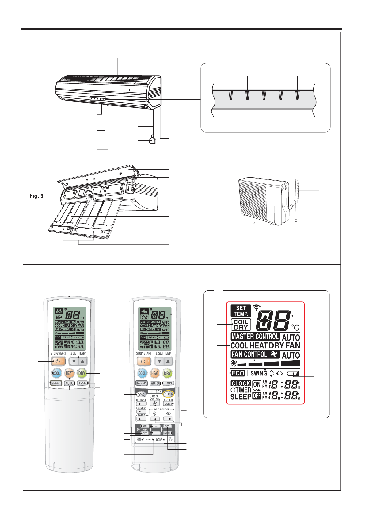
This
ure shows the control display when all indicator lamps are on. It may differ from the actual display
Page 5
NAME OF PART
S
take Grilles
)
(Fig. 2)
TIMER Indi
)
g
).
)
)
)
r
n
,
g
e
time o
stallation.
.
y
n
ust Bo
ectio
er
)
ffuser
d
g
t
t
)
r
y
y
Transmit
cator
T
y
y
n
(
butto
butto
AUTO button
butto
button
n
butto
butto
button
A
A
n
)
TES
butto
butto
n
n
V Lamp (4 position
ndicator
cator Lamp (green
If the TIMER indicator lamp flashes when the
timer is operatin
ccurred with the timer setting (See Page 24
Auto Restart
, it indicates that a fault has
PERATION Indicator Lamp (red
UPER QUIET Indicator Lamp (green
HI-POWER Indicator Lamp (orange
Remote Control Signal Receive
MAINTENANCE/MANUAL AUTO butto
When kept on pressing the MANUAL AUTO
button for more than 10 seconds
coolin
The forced cooling operation is used at th
Only for authorized service personnel's use
When the forced cooling operation starts b
any chance, press the START/STOP butto
to stop the operation.
operation will start.
f in
the forced
Air Filter
D
Air Flow Dir
x
n Louv
Right-Left Louver
behind Air Flow Direction Louver
Power Di
Power Supply Cor
Power Supply Plu
Intake Por
utlet Por
e Unit
rain Port (bottom
ignal Transmitte
IL DRY Displa
perating Mode Display
AN CONTROL Displa
CONOMY Operation
Indi
emperature Display
WING Display
attery Indicator Displa
N TIMER Display
FF TIMER Displa
TART/STOP butto
ET TEMP. button
OOL button
button
EAT
LEEP
AN
n
n
n
IL DRY
button
I-POWER button
UPER QUIET butto
AN CONTROL
ECONOMY
n
n
WING
IR DIRECTION (Left-Right) button
IR DIRECTION (Up-Down) button
N TIMER butto
FF TIMER button
ET TIME buttons ( /
ET (TIMER) button
ANCEL (TIMER) button
T RUN
RESET
n
n
LOCK ADJUST butto
Page 6
●
(Fig
s
about 10
utes
g
s
.
e
.
About the
butto
●
d
p
●
t
R
●
o
e
●
ill chang
g
●
e
)
T
REPARATI
ON
t
th
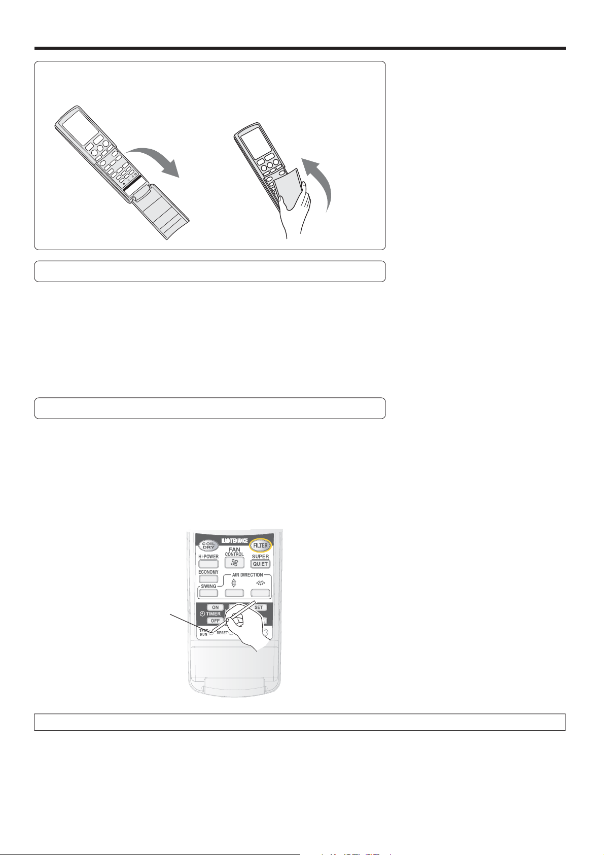
How to open and close the remote control's cover.
Open gently (do not b
too rough)
Take hold of both sides
the cover, and inser
e cover into its place
ntil you hear a click.
Prompts to change remote control's batteries
emote control periodically starts and stops.
attery Indicator Display
At start-up: blinks 5 time
At shut-down: remains lit for
If the Battery Indicator Display is shown, please chan
ossible, even if your remote control is still usable
.6 V shown during operations.
min
.
e your batteries as soon a
TEST RUN
This button is used when installing the air conditioner and should not be use
under normal conditions, as it will cause the air conditioner’s thermostat function to o
If this button is press during normal operation, the unit will switch to the tes
peration mode and the OPERATION Indicator Lamp (red) (Fig.2 6 and TIME
Indicator Lamp (green) (Fig.25) on the Indoor Unit will flash simultaneously.
To the stop the test operation mode, press the START/STOP button (Fig.5 Y t
top the air conditioner.
erate incorrectly.
EST RUN button
n
About the Compulsory Cooling Mod
If the TEST RUN button (Fig.5q is pressed during the cooling mode, the unit w
and the room will be cooled re
Use the compulsory cooling mode to collect refrigerant in the outdoor unit before moving the air conditioner. (Do not us
this button under normal conditions.
5
e to the compulsory cooling mode
ardless of the thermostat setting.
Page 7
Tu
rn on the Pow
er
;
.
)
-
.
batteries
(
+/-
y.
.
n
n
,
r
a
e
the clock to the current time.
butto
ess to advance the time
butto
ess to reverse the time
p
y
)
Thi
k.
To Use the Remote Control Unit
●
ly.
●
.
●
Wh
ill
d.
●
ote Control Unit Holder
●
●
W
t
f
e
ible leakag
d
.
●
.
●
d
r
l
y.
●
●
n
e
r
.
use
g
e
c
The B
n
ibl
s
close to
door Unit
ote Control Unit is unable
ly
T
1
.
2
3
-
.
s
t
Connect the Power Supply Plug (Fig. 1
to an electrical outlet
in the case of a direct line connection, turn on the circuit breaker
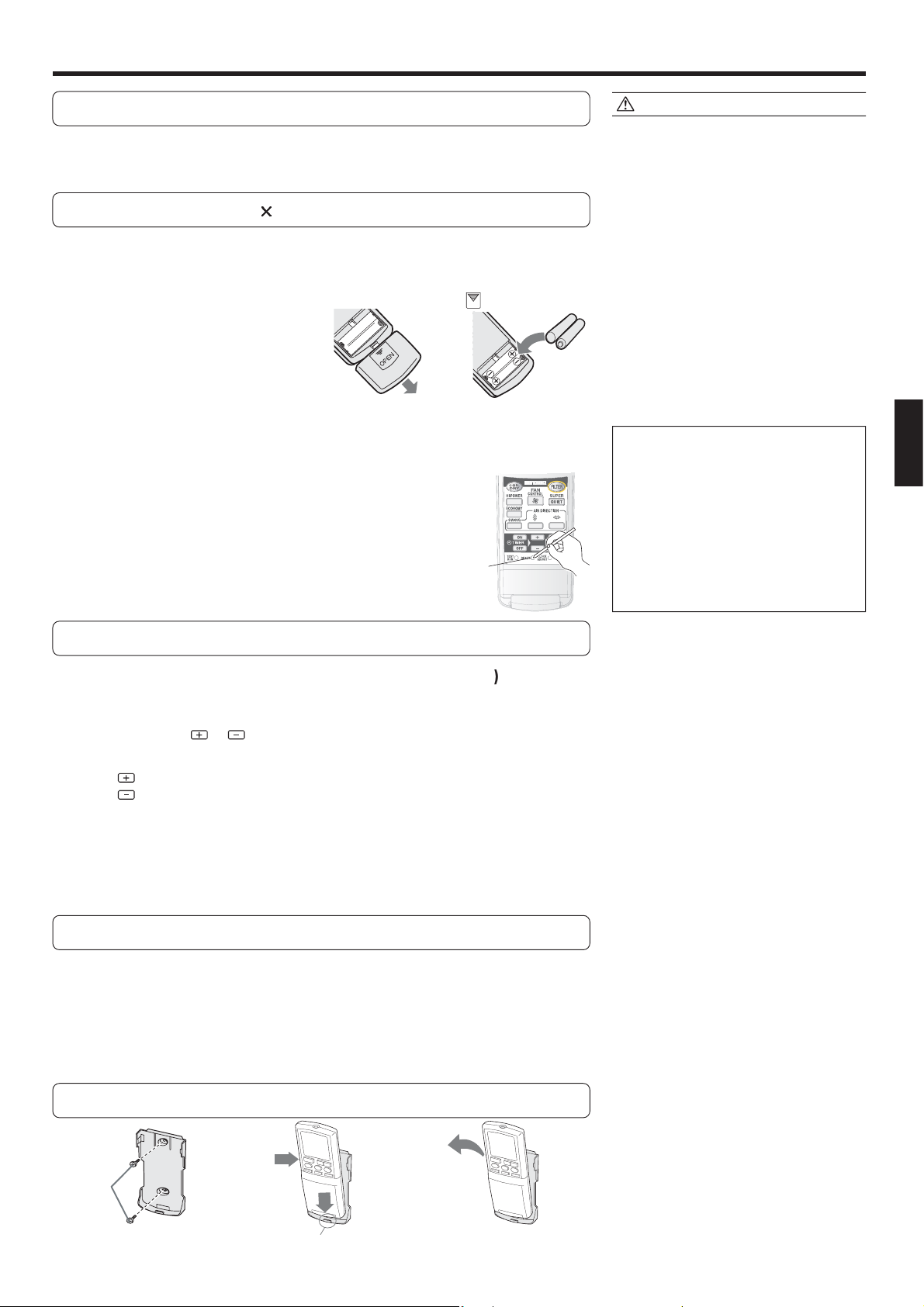
oad Batteries (LR03
2
Press and slide the battery compartment lid on the re
1
verse side to open it.
lide in the direction of the arrow while pressing the mark
2
nsert
e sure to align the battery polarities
.
correctl
lose the battery compartment lid
3
About the RESET (Fig.5 r
4
If the remote control is unable to functio
normally after the batteries are changed
please press the RESET button (Fig.5
Press the RESET button (Fig.5 r using a
all-point pen or other such items with
elatively sharp tip.
butto
RESE
n
CAUTION!
Take care to prevent infants from
accidentally swallowing batteries.
hen not using the Remote Control Uni
or an extended period, remove th
atteries to avoid poss
amage to the unit
If leaking battery fluid comes in contact
with your skin, eyes, or mouth, immediately wash with copious amounts of
water, and consult your physician
ead batteries should be remove
uickly and disposed of properly, eithe
y placing in a public battery collection
receptac
authorit
Do not attempt to recharge dry batteries.
Please always press the RESET butto
after changing batteries to avoid th
In any of the followin
hange your batteries.
•
• No data transmission poss
• The Rem
e, or by returning to appropriate
ossibility of functional errors.
ever mix new and used batteries, o
atteries of different types
atteries should last about one year
nder normal
attery Indicator Display is show
to work proper
.
situations, pleas
In
e an
e unles
the Current Tim
Press the CLOCK ADJUST button (Fig. 5
1
Use the tip of a ball-point pen or other small object to press the button.
the / SET TIME buttons (Fig. 5
)to adjust
2
n: Pr
n: Pr
(Each time the buttons are
ne-minute steps.hold the buttons depressed to change the time quickl
in ten-minute steps.
ressed,the time will be advanced/reversed in
Press the SET button (Fig. 5
3
The Remote Control Unit must be pointed at signal receiver (Fig. 19) to operate
correct
Operating Range: About 7 meters
en a signal is properly received by the air conditioner, a beeping sound w
e hear
If no beep is heard, press the Remote Control Unit button again.
s completes the time setting and starts the cloc
.
.
.
Rem
Inser
crew
ount the Holder
ress in
Set the Romote Control
nit.
Pull out
To remove the Remote Con
trol Unit (when use hand)
Page 8
PERATION
To S
.
[
]
\
a
O
ill light.
Y
To Set the
ostat
g.
C
C
C
temp
.
To S
.
:
A
When set to AUTO:
C
g:
A
g,
:
-
ture of the a
ssued
door unit is lo
:
T
:
)
●
T
.
.
●
.
●
COOL
Wh
8
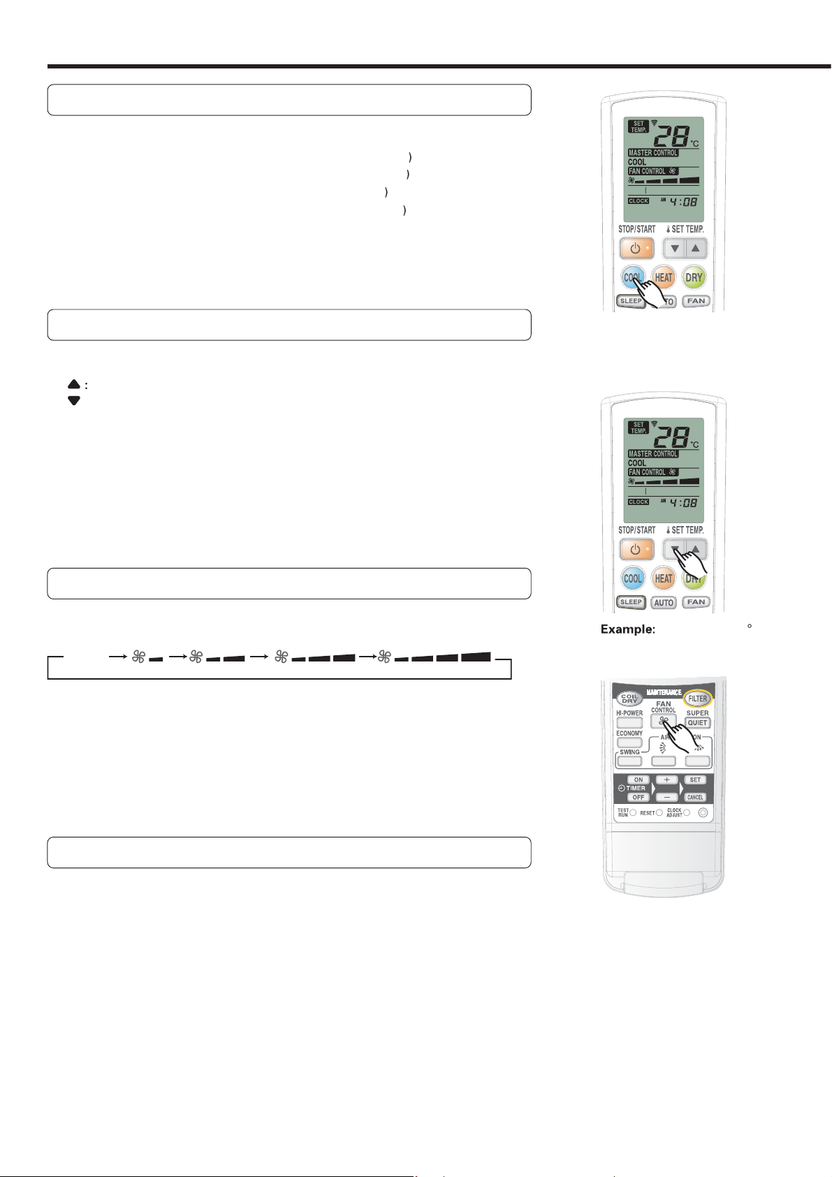
elect Mode Operation
ress the necessary Operation button
ooling Operation: Press the COOL button (Fig.5
Heating Operation: Press the HEAT button (Fig.5
ry Operation : Press the DRY button (Fig.5
Auto Operation : Press the AUTO button (Fig.5
an Operation : Press the FAN button (Fig.5b)
The Indoor Unit's
The Air conditioner will start operating.
Pressing the unit's START/ STOP button (Fig.5
ecently-used mode.
PERATION Indicator Lamp (red) (Fig.26 w
) will run the unit in its most
Therm
Press the SET TEMP. button (Fig. 5 Z).
ress to raise the thermostat settin
ress to lower the thermostat setting.
Thermostat setting range:
ooling/Dry........................ 18 to 30 °
eating............................... 16 to 30 °
AUTO.................................. 18 to 30 °
The thermostat can not be used to set room temperature during the FAN Mode (the
erature will not appear on the Remote Control Unit’s Display)
et the Fan Speed
ress the FAN CONTROL button (Fig. 5
ach time the button is pressed, the fan speed changes in the following order
AUTO
bout three seconds later, the entire display will reappear.
oolin
Heating
an
s the room temperature approaches that of the thermostat settin
the fan speed becomes slower.
Fan operates so as to optimally circulate warmed air.
owever, the fan will operate at very low speed when the tempera
ir i
he fan operates at the low speed.
from the in
)
w.
xample:When set to
en set to 2
Super Quiet Operation
ress the SUPER QUIET button(Fig.5
The Indoor Unit's SUPER QUIET Indicator Lamp (green) (Fig.2 7) will light. (No
isplay on the Remote Control Unit
SUPER QUIET operation begins.
The Indoor Unit's airflow will be reduced for quieter operation.
In SUPER QUIET mode, any of the changes listed below will switch SUPER QUIE
Operations off
Changing the Fan Speed.
Switching to HI-POWER Operation
When the Air Conditioner's operations are stopped, SUPER QUIET Operation is
cancelled. When the unit is started again, it will run at the Fan Speed displayed
n the Remote Control Unit's FAN CONTROL Display
uring SUPER QUIET Operation, Heating and Cooling and Dry performance will
e reduced somewhat.
Page 9
To S
top Operation
●
W
-
-
ture is more tha
n
-
ture is
n
-
t
H
n
●
Wh
m
th
ill begi
r
b
ill
g, C
-
.
ostat set
ting
●
●
.
●
W
y
r
.
●
W
h
f
o
-
.
●
y:
●
.
●
Y
●
t
t
:
●
The H
ill
.
:
m
s
t
e
-
:
Y
l
yo
oom.
ress the START/STOP button (Fig.5
The OPERATION Indicator Lamp (red) (Fig. 2 6 will go out.
About AUTO CHANGEOVER Operation
AUTO:
hen AUTO CHANGEOVER operation first selected, the fan will oper
te at very low speed for about one minute, during which time the unit
etects the room conditions and selects the proper operating mode.
the differance between thermostat setting and actual room tempera
f the difference between thermostat setting and actual room tempera
within ±2
the difference between thermostat setting and actual room tempera
ure is more than
en the air conditioner has adjusted your roo
e thermostat setting, it w
operation mode, the fan will operate at low speed. If the room temperature su
select the appropriate operation (Heatin
erature to the value set in the thermostat
The monitor operation range is ±2
.)
f the mode automatically selected by the unit is not what you wish,
select one of the mode operation (HEAT, COOL, DRY, FAN).
About Mode Operation
eating:
Cooling:
Dr
an
se to warm your room
hen Heating mode is selected, the air conditioner will operate at ver
low fan speed for about 3 to 5 minutes, after which it will switch to the
elected fan setting. This period of time is provided to allow the indoo
nit to warm up before begin full operation
hen the room temperature is very low, frost may form on the outside
nit, and its performance may be reduced. In order to remove suc
rost, the unit will automatically enter the defrost cycle from time t
time. During Automatic Defrosting operation, the OPERATION Indica
tor Lamp (red) will flash, and the heat operation will be interrupted
se to cool your room.
se for gently cooling while dehumidifying your room
ou cannot heat the room during Dry mode.
During Dry mode, the unit will operate at low speed; in order to adjust
room humidity, the Indoor Uni
he fan may operate at very low speed when adjusting room humidity.
se to circulate the air throughout your room.
n +2
Cooling or dry operatio
Monitor operatio
eating operatio
n monitor operation. In the monito
sequently changes, the air conditioner w
ooling) to adjust the tem
relative to the therm
once again
-
uring Heating mode:
et the thermostat to a temperature setting that is higher than the current room
temperature.
erate if the thermostat is set lower than
the actual room temperature
uring Cooling/Dry mode
et the thermostat to a temperature setting that is lower than the current roo
temperature. The Cooling and Dry mode
will not operate if the thermostat is se
er than the actual room temperatur
(in Cooling mode, the fan alone will oper
ate).
uring Fan mode
ou can not use the unit to heat and coo
ur r
eating mode w
not
Page 10

ADJUSTING THE DIRECTION OF AIR CIRCULATI
ON
●
.
●
V
●
w
●
ect the desired a
ectio
t
●
.
●
You can select the desired a
ectio
●
door Unit is set fo
t
.
●
Wh
i
ectio
au-
t
h
th
g,
w
●
t
g
.
●
W
t
c
-
d
●
o
w
●
t
n
/
ill
-
.
●
.
12345678
ote Control Unit
.
ow
w
R
●
n
high
e
A
s
Adjust the up, down, left, and right air directions with the AIR DIRECTION buttons on the Remote Control Unit
Use the AIR DIRECTION buttons after the Indoor Unit has started operating and the airflow-direction louvers have
stopped moving.
ertical Air Direction Adjustment
pen the lid on the Remote Control Unit.
ress the AIR DIRECTION (Up-Down) button. (Fig. 5
When the AIR DIRECTION (Up-Down) button (Fig.5k) is pushed, the airflo
irection changes within the range to the following.
You can sel
Cooling/Dry range1234 Heating range5678
ir flow-direction
ver
* The Remote Control Unit
splay does not change.
irflow dir
4
* The up/down airflow-direction louvers move in the
irection of the arrow from the closed position
In order to maximize the heating and cooling
n.
1
2
3
8
5
6
7
erformance, use the ranges above
an range
ANGER!
ever place fingers or foreign objects inside the outlet ports, since the internal fa
operates at
ersonal injury.
About airflow direction adjustments
en the unit is turned on or the op-
erat
on mode is changed, the position
the airflow-dir
omatically set as listed below to matc
e operation mode (heating, coolin
etc.) selected.
ooling/Dry/Fan:1 horizontal airflow
eating:7 downward airflo
During HI-POWER operation (see page
12), the up/down airflow direction is se
utomatically to optimize the heatin
nd cooling performance
hen the AIR DIRECTION buttons on
he Remote Control Unit are pressed,
t may take a short time for the up/
down airflow-direction louvers or the
eft/right airflow-direction louvers to
reach the desired position.
uring that time, the airflow direction
annot be adjusted even if the AIR DI
RECTION buttons are repeatedly
presse
uring the monitor period in the aut
ode (see page 7), horizontal airflo
rection is set and cannot be adjusted.
f the AIR DIRTCTION (Up-Down) but-
on is pressed during the up/dow
wing operation (see page 11), the up
own swing operation w
ddition, if the AIR DIRECTION (Left
ight) button is pressed during the left/
right swing operation, the left/right
wing operation will stop.
speed and could caus
n louvers is
.
stop. In
Right-Left Adjustmen
Open the lid on the Remote Control Unit.
ush the AIR DIRECTION (Left-Right) button (Fig.5
When the AIR DIRECTION (Left-Right) button (Fig.5j) is pushed, the airflow
irection will change in the following order
Left airflo
The In
is turned on
ight airflow
ront airfl
irflow dir
r front airflow when the uni
.
n.
* The Rem
splay does not change
Page 11

0
WING OPERATI
ON
T
n
n
.
ill light.
e
f
T
A
.
e
f
-
.
Airf
.
e
g
.
Airf
.
-
w
●
.
w
.
●
e
●
d
Begin air conditioner operation before performing this procedure.
o select SWING Operatio
pen the Remote Control Unit lid to perform swing operatio
settings
ress the SWING button (Fig. 5
The SWING Display (Fig. 6U w
ach time the SWING button is pressed, the swing operation will change in th
ollowing order.
Up/down swing operation Left/right swing operation
Swing operation stops Up/down/left/right swing operation
o stop SWING Operation
.
ress the SWING button (Fig.5 i
irflow direction will return to the setting before swing was begun
and select STOP.
About Swing Operation
● Up/down swing:Swing operation begins using th
ollowing range according to the current airflow direc
tion
low direction is 1
With the upper airflow-direction louver in th
horizontal position, the lower airflow-direction
louver moves (swin
area
low direction is 58 (for heating, fan)
With the airflow-direction louvers set for down
ard or straight down airflow, airflow is directly
ainly at the floor.
4 (for cooling, dry, fan)
s) to direct airflow to a wide
Left/right swing: The airflow-direction louvers move
swing) in the left/right airflow direction
● Up/down/left/right swing: The airflow-direction louvers
ove (swing) in both the up/down and left/right airflo
rections
The SWING operation may stop temporarily when th
r conditioner
t very low speeds.
If the AIR DIRECTION (Up-Down) button is presse
during the up/down swing operation, the up/down
wing operation will stop and if the AIR DIRECTION
Left-Right) button is pressed during the left/right swing
operation, the left/right swing operation will stop.
1
Page 12

TIMER OPERATI
ON
ess the CANC
button.
s
S
.
To Use the O
R
P
.
.
door Unit
6
s
-
(Fig
.
e.
utton:
Press to advance the time
ces
utes
.
utto
e
ote Control Unit towards the
door Unit
g
p
T
door Unit
6
desired times for O
.
sectio
Use the O
set the desired
e
door unit
5
.
.
T
.
TIMER Indi
ill go
T
R
o
.
ess the CANC
butto
T
n
d
TIMER b
3
ess the S
button.
T
O
g
.
Ab
●
o
●
t
l
t
●
g
y
.
efore using the timer function,be sure that the Remote Control Unit is set to the correct current time (See page 6)
FF TIMER or ON TIME
Open the Remote Control Unit lid to perform the timer function settings.
To Cancel the Timer
Pr
EL
Press the desired Operation button or START/STO
1
button (Fig. 5
)
(if the unit is already operating, proceed to step 2)
The In
Select the desired timer operation time, and then pres
2
the OFF TIMER button (Fig. 5
ton
The OFF or ON timer indicator flashes
. 5
Use the SET TIME buttons (Fig. 5
3
ired OFF time or ON tim
B
ncrements
B
n:Press to reverse the time.The time goes backward in 5-minut
ncrements.
or the ON TIMER but
to adjust the de-
.The time advan
Point the Rem
4
nd press the SET button (Fig. 5
The OFF or ON timer Indicator stops flashing.
The TIMER Indicator Lamp (
If the ON TIMER function is selected, the air conditioner o
reen) (Fig.25)on the Indoor Unit will light.
o Use the Program timer
Press the START/STOP button (Fig. 5
1
(if the unit is already operating, proceed to step 2).
The In
2
Th
the
the
and times.
in
n “To
FF timer and ON timer
FF timer or ON timerto
will light.
in 5-min
In
eration stops.
will light.
) will light
To Change the Timer Setting
Perform operations 2–4.
To Stop Air Conditioner Operation
while the Timer is Operating
Press the
o Cancel the Timer
Press the CANCEL button
out.Canceling the OFF TIMER or the ON
IME
. Press the TIMER button of the function t
cancel (OFF or ON)
2. Pr
o Change the Timer Settings
. Press the TIMER button of the functio
to change (OFF or ON).
2. Set the timer using the
. Pr
o Stop Air Conditioner Operation
while the Timer is
Press the START/STOP button
TAR T/STOP button
cator Lamp (green) w
EL
uttons.
ET
n.
peratin
an
out the Program timer
The PROGRAM timer allows you to integrate OFF timer and ON timer operations
n a single sequence. The sequence can involve one transition from OFF timer t
ON timer,or from ON timer to OFF timer,within a twenty-four hour period.
The first timer function to operate will be the one set nearest to the current
ime.The order of operation is indicated by the arrow in the Remote Contro
ni
ne example of PROGRAM timer use might be to have the air conditioner auto-
matically stop (OFF timer)after you
n the morning before you arise
ON,or OFF ←ON).
o to sleep,then start (ON timer)automaticall
Page 13

LEEP TIMER OPERATI
ON
0
0
0 5.0
0
)
)
To Use the S
er
g
:
door Unit
6
-
t
.
T
gs
g
.
f
:
e
-
.
T
CANC
.
T
r
Op
/
.
nlike other timer functions, the SLEEP timer is used to set the length of time until air conditioner operate is stopped
LEEP tim
While the air conditioner is operating or stopped, press the
SLEEP button (Fi
ach time the button is presssd, the time changes in the following order
. 5
.
2.
.
3.
7.
9.0(hour
o Cancel the Timer:
Press the
o Stop the Air Conditioner During Time
eration:
Press the START
EL (TIMER) button
STOP button
The In
or Lamp (green) (Fig. 2 5) light
and the TIMER Indica
o Change the Timer Settin
ress the SLEEP button (Fig.5
once to display the last setting time.
Press the SLEEP button (Fi
ach time the button is pressed, the time changes in the following order (Change
rom the last setting time)
.0 →
.0 →
.5
again to change the time
.0 → 5.0 → 7.0 → 9.0(hour
nfirmation of TIMER's tim
The left time of the TIMER which is being set currently will be displayed for 5 min
Page 14

3
ON
.
T
n
.
T
n
.
●
.
●
p
.
●
p
g.
e
.
A
n
The Ind
ill op
During h
2
●
e
n
●
e
door Unit is
eased.
E
CONO
p
.
T
n
To S
A
n
A
.
W
y
.
.
●
●
.
●
f
Begin Air Conditioner operation before performing this procedure.
O
en the Remote Control Unit lid
MY OPERATION
o Use the ECONOMY Operatio
ress the ECONOMY button (Fig.5
"ECO" appears on the Remote Control Unit display.
conomy operation begins.
top the ECONOMY Operation
ress the ECONOMY button (Fig.5
"ECO" disappears from the Remote Control Unit display.
ormal operation begins.
again.
bout ECONOMY Operatio
t the maximum output, ECONOMY Operation is approximately 70% of normal air conditioner operation for cooling and
eating
hen ECONOMY operation is performed during the cooling mode, dehumidification is improved. This function is especiall
onvenient when you want to remove the humidity in the room without significantly lowering the room temperature
During ECONOMY operation, the thermostat setting automatically changes according to the temperature to avoid Unnecessary cooling and heating for the most economical operation
If the room is not cooled(or heated) well during economy operation, select normal operation.
Once air conditioner operation is stopped, normal operation begins when the indoor unit is turned on again
During the monitor period in the AUTO mode, the air conditioner operation will not change to ECONOMY operation even i
ECONOMY operation is selected by pressing the ECONOMY operation button.
I-POWER OPERATI
Begin Air Conditioner operation before performing this procedure.
Open the Remote Control Unit lid
o Use the HI-POWER Operatio
The Indoor Unit's HI-POWER Indicator Lamp (orange) (Fig.2 8 will light.
The Indoor Unit's HI-POWER Indicator Lamp(orange) (Fig.2 8) will go out
● During fan mod
● During cooling mode
●
1
ress the HI-POWER button(Fig.5
I-POWER operation begins
.
o Stop the HI-POWER Operatio
ress the HI-POWER button(Fig.5 e
ormal operation begins.
owever, HI-POWER operation will automatically stop under the following conditions.
If SUPER QUIET Operations are selected during HI-POWER Operation, HI-POWER will be cancelled
During cooling mode
The room tem
During heating mode
The room tem
5 minutes has passed since the HI-POWER operation began
erature is 1
erature is 2
below the thermostat setting or 30 minutes has passed since the HI-POWER operation began
above the thermostat settin
again.
bout HI-POWER Operatio
oor unit w
eating mode
The Indoor unit will operate at maximum power until the room temperature is
During dry mod
The airflow can not be set during HI-POWER operatio
During fan mod
The airflow from the In
erate at maximum power until the room temperature is 1
incr
below the thermostat setting.
above the thermostat setting.
Page 15

IL DRY OPERATION
●
of
g.
●
y.
T
r
.
.
p-
c
g
.
T
ion.
ill g
●
!
●
g
m
idi
e
lightly.
●
●
w
.
n
p
.
1
g
terior of the
door unit
odors are to be removed
ter.
2
)
f
f
,
.
3
p
After allowing the interior of the indoor unit time to dry, run the UV filter clean, to limit mold and bacteria on the interir
the unit and on the air filter. This function shows clear results after cooling or dehumidifyin
For COLID DRY Operation, press the COIL DRY button. Cleaning operations will run for about 20 minutes and stop automati-
call
o start COIL DRY Operation
ress the COIL DRY button (Fig.5
(when the air conditione
is operating or stopped)
Only the OPERATION Indicator Lamp (red) (Fig2.6)on the Indoor Unit will light
IL DRY
roximately 20 minutes.
If the COIL DRY button (Fig5.
DRY operation will start a
appears on the Remote Control Unit display and disappears after a
) is pressed again during COIL DRY operation, COIL
ain
o stop COIL DRY Operation
ress the START/STOP button (Fig.5 Y
during COIL DRY op-
erat
The OPERATION Indicator Lamp (red) (Fig2. 6on the Indoor Unit w
The Remote Control Unit will be in the operation-stopped condition.
About COIL DRY Operatio
The following procedures are performed during COIL DRY operation before the
eration automatically stops after approximately 20 minutes
o
ryin
After about 18 minutes of COIL DRY Operation, drying shall be performed on the
in
fil
UV filter cleaning (about 2 minutes
UV rays are discharged onto the air filter, so that all dirt, odor, and dust undergo
disin
ecting and deodorizing processing, and are recycled into the dust box. At
the same time, the air
and returned to cleaning mode
Operations sto
The COIL DRY operation come to an end.
in
. All dirt and foul
ilter's disinfecting and deodorizing functions are reset
o out.
from the air
NOTE
When COIL DRY operation begins, the
ndoor Unit operates in the heatin
mode and the fan mode to dry the inside
of the Indoor Unit. As a result, the roo
temperature and hum
s
IL DRY operation cannot be used to
clean the air in the room.
COIL DRY operation is most effective
hen performed frequently
ty may ris
Page 16

AUTO FILTER MAINTENANCE FUNCTI
ON
●
●
CAUTION!
o
filte
●
e
●
g
A
Fil
e
●
g
●
)
2
4
.
out
●
t
n
l).
2
t
●
s
door Unit.
●
-
t
.
s
f
r
f
.
l
.
f
W
OCK
S
.
s
.
n
.
.
.
o
o
k
This is a convenient function that automatically removes dust from the air filters after a set amount of time of air conditione
peration.
The auto filter maintenance function can also be started using the remote control unit.
uto
ter Maintenanc
About operating the Auto Filter Maintenance
Auto filter maintenance is performed after the air conditioner operates for a set
amount of time and is stopped or the FILTER button (Fi
ontrol Unit is pressed.
During auto filter maintenance, the MAINTENANCE SIGN Indicator Lamp (red
(Fig.
) on the Indoor Unit will light
.5d on the Remote
. Air filters come
The air filters automatically come out of the indoor unit under the open panel. A
this time, the dust on the air filters is collected in the dust boxes (behind the ope
ane
Open panel
. Air filter retrac
After the air filters come out, they automatically retract to their original position
in the In
Do not touch the air filters during the aut
r maintenance.
The Indoor Unit may malfunction if th
air filters are pulled or pushed.
the air filters are unnecessarily pulled,
they may be dama
ersonal injury.
ed or fall and cause
When the auto filter maintenance is complete, the MAINTENANCE SIGN Indica
or Lamp (red) (Fig.24) on the Indoor Unit goes out
MAINTENANCE SIGN Indicator Lamp(red) flashe
The MAINTENANCE SIGN Indicator Lamp (red) (Fig.24 will flash during auto filter
maintenance i
onditioner operation, unplug the power supply cord from the Electrical outlet and
ollow procedures "Dust Box Maintenance" to install the air filters
hanging the FILTER MAINTENANCE Interva
The filter maintenance interval can be changed
ome dust may be tough to clear away with Auto Filter Maintenance.
In such a situation, please switch the Interval to 50H
hile cleaning, please place the remote control in stop mode (so that only the CL
nd the time are displayed).
1. Hold down the
witches from displaying the current time to displaying the interval, and begin
blinking
. Set the interval using the SET TIME button's and keys (Fig.5
ressing these buttons will allow you to scroll between the figures below
H
actory settings are 100H
or more detailed FILTER MAINTENANCE, set to 50H
. Point the remote control to the main unit and press the SET button (Fig.5
The display will stop blinking and send signals to the Indoor Unit.
If you do not press the SET button (Fig.5
time settings.
the air filters are not Installed or are pulled. If this occurs during ai
or more thorough cleaning.
ET TIME button (Fig.5 n for at least 3 seconds
H
), there is no way to save the wor
15
Page 17

6
A
t
FILTER b
(Fig
ill light.
A
●
-
r
w
●
g
.
●
C
g
●
s
.
●
r
R
s
N
●
T
●
t
Fil
2
4
illumi
About the Auto Filter Maintenance function
●
d
f
m
.
●
f
●
s
o
).
●
●
e
t
.
A
.
●
g
.
●
l
.
n
d
s
000 hours
s
000 hours
Depending on how dirty the air filters are, all of the dust may not be remove
rom the air filters during the auto filter maintenance. In this case, perfor
auto filter maintenance again
If dust remains on the air filters after auto filter maintenance has been per-
ormed a number of times, perform dust box maintenance (see page 17)
Depending on the condition of the dust on the air filters, such as if the dust i
particularly oily or hardened, the dust may not be removed during the aut
FILTER MAINTENANCE. In this case, remove the air filters and clean with water
see page 20
During auto filter maintenance, clicking or hissing sounds may be producd.
During FILTER MAINTENANCE, if you pull or push the filter upwards, th
FILTER MAINTENANCE process will stop and the MAINTENANCE SIGN Indica-
or Lamp (red) (Fig.24 will blink
t this time, please refer to Dust Box Maintenance, FILTER Installation
If the FILTER is inserted too low, it will automatically correct itself by movin
pwards
If there are any objects located under the indoor unit, should the FILTER fal
out, it would hit these objects and would no longer be able to work properly
UTO Filter Maintenance using the Remote Control Uni
ress the
tton
.5
(When the Air Conditioner is operating or stopped.)
The MAINTENANCE SIGN Indicator Lamp (red) (Fig.2 4 on the Indor Unit w
uto filter maintenance begins.
If the FILTER button is pressed during Air Conditioner operation, the Air Condi
tioner will stop, auto filter maintenance will be perfomed, and the air conditione
ill start operating again after the auto filter maintenance is complete.
Even if the FILTER button is pressed during the auto filter maintenance, the cleanin
will not stop
About the notification for Dust Box cleaning
When auto filter maintenance is not activated, but the Indoor Unit's MAINTENAN
E SIGN Indicator Lamp (red) (Fig.24) is illuminated, this means that it is
time to perform dust box cleanin
x.
ue to differences in Auto Filter Maintenance intervals, there are also difference
in the amount of time that an air conditioner runs before its MAINTENANCE
IGN Indicator Lamp (red) (Fig.24 is lit
Auto filter maintenance interval Interval before maintenance sig
hour
100 hour
. In such a situation, please clean your dust
ndicator lamp (red) is illuminate
2
4
While the MAINTENANCE SIGN Indicator Lamp (red) is illuminated, Auto Filte
Maintenance will not work. (Even if you press the Remote Control Unit's FILTE
utton, it will not run). In such a situation, please clean the DUST BOX, and pres
the MAINTENANCE/ MANUAL AUTO button (Fig.3A . The MAINTENANCE SIG
ndicator Lamp (red) (Fig.24 will go out.
he MAINTENANCE SIGN Indicator Lamp (red) will only light up when the Air
onditioner is running or coming to a halt.
you put out the MAINTENANCE SIGN Indicator Lamp (red) (Fig.24 withou
cleaning the Dust Box, the next time that Auto
pill out from the unit. When the MAINTENANCE SIGN Indicator Lamp (red) (Fig.
is
nated, please be sure to clean the Dust Box.
ter Maintenance runs, dust may
1
Page 18

ERFORMING MAINTENANCE
●
●
e
ectrical outlet
ce
●
n
e
.
●
from the dust boxes.
●
S
●
.
e
(The p
ill
n
)
2
dust box's loc
e
the lock.
3
-
)
r
out
dust bo
ection of the arrow.
●
W
r
.
requent maintenance will extend the life of the air conditioner and improve the cooling and heating performance.
efore maintenance, stop air conditioner operation using the remote control and unplug the power supply cord from th
l
.
CAUTION!
Before cleaning the air conditioner, be sure to turn it off
and unplug the power supply cord from the electrical
outlet.
The internal fan operates at high speed and could cause
personal injury.
When removing the dust boxes and grill, do not touch any
metal parts (heat exchanger, etc.).
Personal injury may result.
When cleaning the air conditioner, do not stand on any
unstable objects.
You might fall and personal injury could result.
When cleaning the dust boxes and grill, be sure to install
them securely.
If the dust boxes and grill are not properly installed,
they could fall and cause personal injury.
Box Maintenan
If the MAINTENANCE SIGN Indicator Lamp (red) (Fig.2 4) on the Indoor
Unit is lit, be sure to clean the dust boxes. If the Indoor Unit is installed i
an area with a lot of dust, clean the dust boxes every 3 months even if th
MAINTENANCE SIGN Indicator Lamp (red) (Fig.2 4) is not lit
When cleaning the dust boxes, dust may fall to the floor. Lay newspaper,
etc. under the Indoor Unit before cleaning the dust boxes.
MAINTENANCE SIGN
TIMER OPERATION HI-POWER
SUPER QUIET
1. Remove the dust boxes and air filters from the indoor unit. Remove the air filters
Preparation
top the air conditioner using the Remote Control Unit.
Unplug the power supply cord from the electrical outlet.
. Open the open panel
Open panel
rab both sides of the open panel and fully open th
open panel. Continue to open the open panel past the
orizontal position.
ter it is released.
. Remove the
Dust boxes
anel w
Latches
remain open eve
k.
. Remove the dust boxes and air filters.
rab the center of each dust box, lift the bottom in direc
tion 1, and then remove the dust box in direction 2.
Remove the dust boxes and air filters together.
1
2
4. Remove the air filter from each dust box.
rab the holding position on the air filter and pull the ai
filter
from the
Holding
position
x in the dir
Air filter
“Click”
ove the holding positions (yellow) on either side of the
ust boxes (2 on the left and right) inwards, and remov
“Click”
Dust box
hen the air filter is removed from the dust box, dust
ay fall from the dust box. Lay newspaper, etc. unde
the dust box before removing the air filter
Page 19

8
2
. Remove the
dust collected
dust boxes and clean the dust boxes
.
1
r
d.
2
●
●
pap
3
U
d
●
.
2
cases
ate
1
a-
d
)
2
3
.
4
.
5
Wip
d
y.
ild synthetic l
y
.
y
ff.
●
p
-
o
y
r
f
3. D
1
the i
g.
r
.
●
y
in the
.
. Open the dust boxes
Hold the latch (light blue) on both sides of the interio
of the dust box, and pull outwards until you hear a
catch" soun
Latch
"Click"
Open the interior of the box.
Inner case
Outer case
Be gentle when opening, as excess force may result in
amage and malfunction.
When opening the inner case, dust collected inside the
ust box may fall out. During this process, please place
news
ers or some other cover under the dust box.
"Click"
After washing with water, make sure the dust boxes are
com
letely dry before installation. The brushes are espe
cially difficult to dry so wipe them with a towel, etc. t
ake sure they are completely dry. If the dust boxes are
installed wet, the dust ma
ilters during auto filter maintenance.
not be removed from the ai
ust box installation
First pull down on the outer casing, and then cover up
nner casin
Inner case
Outer case
Put the latches (light blue) on either side into thei
place
"Click"
"Click"
Cleaning the interior of the box.
se a vacuum to clean up the dust on the brush an
the box, or use a brush to wipe this dust away.
Outer case
Brush holder
Brush
Inner case
Do not be too forceful when opening up the brush holder
Otherwise, this may result in damage and malfunction.
. Wash the front and rear
with w
if they are extremely dirty.
Lightly rub the brushes clean with 40–
ter. If the brushes are difficult to clean, apply a mil
ynthetic laundry detergent (low or neutral alkalinity
nd rub lightly.
Rub the front and rear cases lightly with a sponge.
Rinse under running water
Remove the water from the front and rear cases
e the brushes and cases with a towel, etc., an
ace in a shaded area to dr
●
o not use a cleaner other than a m
etergent (low or neutral alkalinity).
●
o not clean with hot water above 60
●
o not clean with any abrasive or hard object
●
o not dry with hot air from a hair dryer, etc.The cases
be deformed and the brushes may come o
ma
.
hot w
aundr
latch
When installing the dust box, please insert the latch di-
rectl
into its correct position. If the latch is not fully in
lace, and the box is installed onto the main unit, Auto
ilter Maintenance will not work.
r
1
Page 20

9
3.
nstall the dust box onto the main unit, press the "MAINTENANCE / MANUAL AUTO" button, and then insert the air filter.
I
.
1
Mak
e
2
Op
e
3
.
●
,
.
●
d
y
t
2. I
pply li
A
1
2
2
4
.
●
"
p
g
.
●
L
butto
uto
be
g
.
3
1
2
t
y
.
nstall the dust box onto the main unit
e sure that the dust box's 2 yellow latches ar
open.
en the front panel and insert the dust box into th
nit until you hear it catch in place.
"Beep"
*If the MAINTENANCE SIGN Indicator Lamp (red) (Fig.
) light is illuminated, it will go out at this point
Press down on the MAINTENANCE / MANUAL AUTO
utton, and release the button when you hear a "beep.
f the MAINTENANCE / MANUAL AUTO button is held
down for more than 3 seconds, MANUAL AUTO O
tion will be
in (page 22)
Please be sure to press the MAINTENANCE / MANUA
AUTO
n. A
Filter Maintenance is unable to
erformed when the MAINTENANCE SIGN Indicator
Lamp (red) (Fi
.2 4 is illuminated
Remove
Latch
Lock
era-
Insert the dust box fully and move the two latches on
ther side outside to lock it in place
Latch
Remove
"click"
Lock
If the latches are locked while installing the dust box
malfunctions may result and the dust box may fall out
During installation, make sure that you have a goo
rip of the middle of the dust box and insert it soundl
in its place. Should there be any errors in installation,
he dust box may fall out and cause injury.
nsert the power su
ne into its socket
and press the MAINTENANCE / MANUAL
UTO button (Fig.3
Insert the power supply line into its socket.
Press the unit's "MAINTENANCE / MANUAL AUTO"
n.
.
. Insert the air filters into the unit (one on
oth the left and right side).
Insert the air filter net into the dust box slot.
Dust Box
INLET
Direc
t
i
o
n
Air filter
Insert the air filter until it reaches the upper limits of
he air filter frame (on both sides). (After about 2 sec-
onds, the air filter will automaticall
Dust box
lock into its place)
1
Mark
Air filter
Air filter
frame
Page 21

A
ce
●
●
e
the dust boxes and a
ge
).
2
.
e
,
.
●
-
●
g
a
y.
●
-
r
●
d
.
●
0
f
f
-
f
sta
dust boxes and a
e
.
)
A
e
)
●
e
d
e
.
●
r
.
e
●
dust
door unit
th
,
●
y
●
y
w
ERFORMING MAINTENANCE
(CO
)
3
Following th
g
r
c
f
in
.
●
.
ically lock i
.
ose the
)
NTINUED
3. Install the dust box onto the main unit, press the "MAINTENANCE / MANUAL AUTO" button, and then insert the air filter. (Continued
e same procedure, insert the other side's
ir filter.
● Durin
● Please insert the air
Insert the air filter to the point designated on the filter
installation, please make sure that both the filter
nd your hands are dry. Any moisture on the filter o
on your hands may result in malfunctions or electri
ock.
ilter correctly according to the
esignated direction. Incorrect insertion may result
xcess noise or functional problems
If the filter is not in the correct position, it may not
automat
4. Cl
nto its place
Front Panel.
ir Filter Maintenan
Wash the air filters with water if small dust particles remain on the air filters even after auto filter maintenance is perform.
t is recommended to perform dust box maintenance when the air filter maintenance is performed.
. Open the open panel, and then remov
ir filters.
Refer to procedure 1 in Dust Box Maintenance (see pa
17
. Remove the air filters from the dust boxes
Refer to procedure 1 in Dust Box Maintenance (see pag
17).
3. Remove the dust with a vacuum cleaner
and then wash the air filters with water
If there is excessive oil or dirt, please wash with syn
thetic kitchen detergent (medium-grade).
Wipe the air filters with a towel, etc., after washin
them with water, and then place them in a shaded are
to dr
Do not bend the air filters. The air filters may be dam
ed and prevent the auto filter maintenance from be-
ng performed. Please pay special attention to the ai
filter frame and the internal gears.
Air filter backside
Do not clean the air filters with any abrasive or har
object. The air filters may be damaged
Do not clean with hot water above 6
● Do not dry with hot air from a hair dryer, etc. The air
ilters may be deformed.
● A
ter washing the air filters with water, do not force
ully shake them dry. The air filters may be damaged.
4. In
ll the
ir filters in th
ndoor unit, and then close the open panel
Refer to procedure 4 in Dust Box Maintenance (see page
16
.
bout the air filter (titanium apatit
micro-filter
With a micro-fiber filter (extra fine) enhanced by th
ddition of titanium apatite, disinfection an
eodorization is performed on dust gathered from th
ir and all types of odorous bacteria
UV rays on the filter's titanium enhance the effects of
isinfecting and deodorizing, and leave the air filte
ompletely clean
Rack (bar with teeth)
ndoor Unit Maintenanc
move the
a vacuum cleaner, wipe the unit with lukewarm water
and then dry with a clean, soft cloth.
o not clean with water above 40
indoor unit ma
o not clean with benzene, paint thinner, or polish. The
ill damage the exterior of the indoor unit.
from the exterior of the in
. The exterior of the
be deformed and become discolored.
wi
Page 22

ERFORMING MAINTENANCE
(CO
)
ce
●
dust bo
e.
ill
●
l inj
.
.
ge
).
2
1
P
g
2
G
.
3
ater.
m
y
t
.
r
.
illes.
1
S
e
ill
)
1
e
y
)
●
e
2
o
t
.
t
g
the
backward and
de.
)
Intake Grille Maintenan
NTINUED
rform
x maintenance at the same tim
Intake grille
. Open the open panel
Refer to procedure 1 in Dust Box Maintenance (See pa
17
. Removing the Intake grille.
ush the grille's holding positions (4) on the interior
of the open panel upwards (releasin
l's four holding positions).
Projections
Projections
the front pan-
CAUTION!
e sure to install the intake gr
the intake grilles are not installed securely, they may fall and
cause persona
ury
es securely.
5. Install the Intake grilles.
Slide Intake grille into the indoor unit along the guid
rails under the open panel until it stop. (Lift up slightl
on the intake grille as it is being installed.
Guide rails
Open panel
Holding positions
rasp the Intake grille's upper holding positions and
ull them forward
. Wash with w
Remove the dust from the intake grilles with a vacuu
leaner, wipe them with lukewarm water, and then dr
hem with a clean, soft cloth
o not clean with water above 40
nit may be deformed and become discolored
The exterior of the indoo
4. Install the intake gr
lide each intake grille into the indoor unit along th
uide rails under the open panel until it stops. (Lift up
tly on the intake gr
e as it is being installed.
Make sure that the intake grilles are installed in th
correct direction. FRONT is stamped on the holding
osition of each intake grille.
Insert the four projections on each intake grille int
he indoor unit in the direction of the arrows shown
Projections
If the intake grilles are not installed properly along the
uide rails until they stop, the projections will not fi
nto the indoor unit. After installation, make sure the
ntake grilles are installed securely by gently movin
m forward and
Projections
from side to si
. Close the open panel.
Refer to procedure 4 in Dust Box Maintenance (See page
17
.
Page 23

ANUAL AUTO OPERATI
ON
.
3
idi
l
.
.
n
)
2
O
●
A
p-
O
ill light.
Th
ill op
g
ill
.
A
ill g
.
se the MANUAL AUTO operation in the event the Remote Control Unit is lost or otherwise unavailable
REMOTE CONTROL UNIT UNAVAILABLE (MANUAL AUTO OPERATION)
If the Remote Control Unit is lost or the batteries are dead, the air conditioner can be operated provisionally from the indoor
nit.
. Open the open panel
rab both sides of the open panel and open the open
panel until it is held in place. (The panel will remain ope
even after it is released.
. Press the MAINTENANCE/MANUAL AUT
utton (Fig.3 A) for 3 seconds.
Press the MAINTENANCE/MANUAL AUTO button (Fig.3
) and continue to press the button even after a bee
ng sound is produced.
The
PERATION Indicator Lamp (red) (Fig.26 on the
ndoor Unit w
e air conditioner w
pa
e 8). Airflow will be automatic, airflow direction will
e the standard setting, and the thermostat settings w
e the standard temperature
erate in the auto mode (see
. Close the open panel.
●
o not operate the air cont
open
oner with the open pane
Stopping MANUAL AUTO Operation
Press the MAINTENANCE/MANUAL AUTO button (Fig.3
ir conditioner operation will stop and the OPERATION Indicator Lamp (red) (Fig.26 on the Indoor Unit w
for 3 seconds.
o out
Page 24

TROUBLESH
OO
G
!
Symptom
oesn
y:
d:
s:
e
A
:
W
m
the outdoor unit:
●
-
t
f
●
-
●
e
r
3
.
●
ligh
This i
f
r
.
●
.
.
●
s
e
●
d
f
f
.
●
.
●
W
y
●
e
ill
r
e
.
●
-
g
ON
●
T
g
m
●
w
.
●
w
d.
●
S
7
UNCTIO
S
t
o
.
:
TIN
WARNING
Before requesting service, perform the following checks
NORMAL
F
D
N
tel
oise is hear
In the event of a malfunction (burning smell, etc.), immediately stop operation, disconnect the
Power
source. Always be sure to disconnect the Power Supply Plug or turn off your circuit breaker t
ensure that power is completely off
t operate immedi-
upply Plug, and consult authorized service personnel.
erely turning off the uni
the unit is stopped and then immediately started again, the com
ressor will not operate for about 3 minutes, in order to preven
use blowouts.
Whenever the Power Supply Plug is disconnected and then re
onnected to a power outlet, the protection circuit will operate for
bout 3 minutes, preventing unit operation during that period.
uring operation and immediately after stopping the unit, th
ound of water flowing in the air conditione
eard. Also, noise may be particularly noticeable for about 2 to
inutes after starting operation (sound of coolant flowing)
uring operation, a s
the result o
ue to temperature changes
uring Heating operation, a sizzling sound may be heard occasional
This sound is produced by the Automatic Defrosting operation
Problem
t squeaking sound may be heard.
minute expansion and contraction of the front cove
ee Page
s
mell
st or steam ar
emitted:
irflow is weak or stops
Some smell may be emitted from the indoor unit. This smell i
the result of room smells (furniture, tobacco, etc.) which hav
n taken into the air conditioner.
uring Cooling or Dry operation, a thin mist may be seen emitte
rom the indoor unit. This results from the sudden Cooling o
room air by the air emitted from the air conditioner, resulting in
condensation and misting
uring Heating operation, the outdoor unit
team may be seen rising from the unit. This is due to Automatic
efrosting operation
hen Heating operation is started, fan speed is temporarily ver
low, to allow internal parts to warm up.
uring Heating operation, if the room temperature rises abov
the thermostat setting, the outdoor unit w
nit will operate at very low fan speed. If you wish to warm th
room further, set the thermostat for a higher setting
uring Heating operation, the unit will temporarily stop opera
tion (between 7 and 15 minutes) as the Automatic Defrosting mode
operates. Durin
ndicator lamp will flash.
Automatic Defrosting operation, the OPERATI
stop, and the indoo
he fan may operate at very low speed during Dry operation or
when the unit is monitorin
uring SUPER QUIET operation, the fan will operate at very lo
peed
n the monitor AUTO operation, the fan will operate at very lo
ee
ater is produced fro
uring Heating operation, water may be produced from the outdoor unit due to Automatic Defrosting operation.
the roo
Page 25

TROUBLESH
OO
G
Symptom
C
s
S
CE
k
●
●
?
●
●
?
●
y?
●
●
y?
●
●
-
●
p
?
●
●
?
●
S
)
TIMER Indi
(Fig
y
l.
e
e
●
-
g
n
w
.
●
by
d.
g
●
m
-
f
.
it i
ipped with
ON
(Fi
AUTO Restart
n
●
a
-
●
●
r
e
g
.
●
r
y
n
.
TIN
HECK ON
RE
Doesn’t operate at all:
Poor
ooling performance:
The unit operate
differently from the Remote
ontrol Unit’s setting:
tems to chec
Is the Power Supply Plug disconnected its outlet?
Has there been a power failure
Has a fuse blown out, or a circuit breaker been tripped?
Is the timer operating
Is the Air Filter dirt
Air the air conditioner’s intake grille or outlet port blocked?
you adjust the room temperature settings (thermostat) cor-
ectl
Is there a window or door open?
In the case of Cooling operation, is a window allowing bright sun
ight to enter? (Close the curtains.)
In the case of Cooling operation, are there heating apparatus and
com
uters inside the room, or are there too many people in the
oom
Is the unit set for SUPER QUIET operation?
Are the Remote Control Unit’s batteries dead
Are the Remote Control Unit’s batteries loaded properly?
ee Page
-
If the problem persists after performing these checks, or if you notice burning smells, or the OPERATION Indicator Lamp (red
. 26 and the
Plug (Fig. 1H, and consult authorized service personne
cator Lamp (green )
. 25) flashes, immediately stop operation, disconnect the Power Suppl
PERATING TIP
Operation and Performanc
Heating Performanc
This air conditioner operates on the heat-pump princi
ple, absorbing heat from outdoor air and transferring that
heat indoors. As a result, the operatin
educed as outdoor air temperature drops. If you feel that
insufficient heating performance is being produced, we
ecommend you use this air conditioner in conjunctio
ith another kind of heating appliance
eat-pump air conditioners heat your entire room
ecirculating air throughout the room, with the result that
ome time may be required after first starting the air con-
tioner until the room is heate
performance is
Microcomputer-controlled Automatic Defrostin
When using the Heating mode under conditions of low
utdoor temperature and high humidity, frost may for
n the outdoor unit, resulting in reduced operating per
ormance
In order to prevent this kind of reduced performance, this
un
s equ
atic Defrosting function. If frost forms, the air condi-
tioner will temporarily stop, and the defrosting circuit will
erate briefly (for about 7-15 minutes).
uring Automatic Defrosting operation, the OPERATI
ndicator Lamp (red)
a Microcomputer-controlled Auto-
g. 2 6) will flash.
In Event of Power Interruptio
The air conditioner power has been interrupted by
ower failure. The air conditioner will then restart auto
atically in its previous mode when the power is restored.
perated by setting before the power failure.
f a power failure occurs during TIMER operation, the time
will be reset and the unit will begin (or stop) operation at th
new time setting. In the event that this kind of timer fault
occurs the TIMER Indicator Lamp will flash (see Pa
Use of other electrical appliances (electric shaver, etc.) o
nearby use of a wireless radio transmitter may cause the
air conditioner to malfunction. In this event, temporaril
disconnect the Power Supply Plug, reconnect it, and the
use the Remote Control Unit to resume operation
e. 4)
Page 26

PERATING TIP
S
bout to 43
bout 18 to 3
e
e
C
About to 43
bout 18 to 3
de
bout to
About 30
ess
T
e
●
f
.
●
g
●
r
T
●
Wh
●
.
emperature and Humidity Rang
A
A
ry Mode
2
ooling Mode
Outdoor temperatur
ndoor temperatur
If the air conditioner is used under higher temperature conditioner than those listed, the built-in protection circuit may
perate to prevent internal circuit damage. Also, during Cooling and Dry modes, if the unit is used under conditions o
lower temperature than those listed above, the heat-exchanger may freeze, leading to water leakage and other damage
o not use this unit for any purposes other than the Cooling, Dehumidifying, and air-circulation of rooms in ordinary
dwellin
If the unit is used for long periods under high-humidity conditions, condensation may form on the surface of the indoo
unit, and drip onto the floor or other objects underneath. (About 80% or more)
s.
A
2
eating Mo
A
24
or l
ips for saving energy
en the outdoor temperature is low (about 10 or less), the unit will consume the power of 20~40W unless the power
plug is disconnected from the outlet even if the air conditioner turns off.
emove the power plug to stop the power supply for energy saving when not using for a long time
5
Page 27

Page 28

 Loading...