

Fujitsu Plasmavision P37FT05AUB, Plasmavision P50FT00AUB, Plasmavision P65FT00AUB, Aviamo P37FT05AUB, Aviamo P50FT00AUB User Manual
...Page 1

USER’S MANUAL
FULL HD DISPLAY
P37FT05AUB
P50FT00AUB
P65FT00AUB
37 / 50 / 65
Before using the display, read this manual carefully so that you know how to use the
display correctly.
Two manuals of the "Safety Precautions" and this "User's Manual"
are supplied with the display. Especially, be sure to read and observe the "Safety Precautions".
Refer to this manual whenever questions or problems about operation arise.
Keep this manual in the place where the user can see it easily.
* Installation and removal require special expertise. Consult your dealer for details.
* The last digit of Model No. (10 digit alphanumeric characters) indicated on the product means
the body color indication alphabet or the management number.
TM
English
Page 2

E-2
CONTENTS
INFORMATION ...................................................................3
ACCESSORIES ..................................................................4
TRADEMARK INFORMATION ................................................. 4
INSTALLATION ..................................................................5
TOPPLING PREVENTION ....................................................... 6
ATTACHING THE FERRITE CORES....................................... 6
PART NAMES AND FUNCTIONS ...................................... 7
DISPLAY SECTION – FRONT ................................................. 7
DISPLAY SECTION – BACK.................................................... 8
REMOTE CONTROL.............................................................. 10
USING THE REMOTE CONTROL ....................................12
PUTTING BATTERIES IN THE REMOTE CONTROL ........... 12
PRECAUTIONS...................................................................... 12
EFFECTIVE RANGE FOR THE REMOTE CONTROL........... 13
BASIC CONNECTION AND PREPARATION OF THE SYSTEM
.... 14
CONNECTIONS TO THE DISPLAY....................................... 14
TO RECEIVE CABLE TV PROGRAMS (WITH CableCARD)
.... 15
TO RECEIVE CABLE TV PROGRAMS (WITHOUT CableCARD)
... 16
TO RECEIVE TERRESTRIAL TV PROGRAMS..................... 16
CONNECTING TO EXTERNAL EQUIPMENT .................. 17
EXAMPLE OF CONNECTING EXTERNAL EQUIPMENT
.... 18
BASIC OPERATIONS .......................................................19
Power ON ............................................................................... 19
Power OFF (standby state)..................................................... 19
VOL (Volume) ......................................................................... 19
MUTE...................................................................................... 19
WATCHING TV, VIDEO, RGB AND IEEE1394 MODE .... 20
TV ........................................................................................... 20
CH RETURN........................................................................... 20
ANTENNA/CABLE.................................................................. 20
VIDEO..................................................................................... 20
RGB ........................................................................................ 20
Link 1394 (IEEE1394)............................................................. 20
CONVENIENT TV AND VIDEO FUNCTIONS .................. 21
FAVORITE (Favorite channels) .............................................. 21
GUIDE (TV Guide On Screen) ................................................ 21
CC (Closed Caption)............................................................... 21
MTS/STEREO......................................................................... 21
TV-INFO (INFORMATION)..................................................... 21
Listening mode NIGHT ........................................................... 21
OTHER BASIC OPERATIONS .........................................22
DISPLAY................................................................................. 22
OFF TIMER............................................................................. 22
PICTURE MODE .................................................................... 22
PICTURE MEMORY............................................................... 22
WIDE....................................................................................... 22
SCREEN SIZE........................................................................ 23
ASPECT RATIO...................................................................... 23
ADJUSTMENT MENU ...................................................... 24
BASIC PROCEDURES OF ADJUSTMENT MENU .......... 25
ADJUSTING TO A DESIRED PICTURE (PICTURE MENU)
.....26
Signal Contrast ....................................................................... 26
Drive Contrast......................................................................... 26
Brightness............................................................................... 26
Color ....................................................................................... 26
Tint.......................................................................................... 26
Sharpness............................................................................... 26
Ambient Sensor ...................................................................... 26
Picture Mode........................................................................... 26
Precision Setting..................................................................... 27
Black Level .......................................................................27
Detail Gradation ................................................................27
3D NR ...............................................................................27
CODEC NR ......................................................................27
Image Enhance ................................................................27
Color Temp. ......................................................................27
User Color Temp. .............................................................27
Color Tuning .....................................................................28
Progressive Scan ............................................................. 28
Gamma ............................................................................. 29
ALC Setting ...................................................................... 29
Picture Memory....................................................................... 30
ADJUSTING TO DESIRED AUDIO (AUDIO MENU) ........31
Treble...................................................................................... 31
Bass........................................................................................ 31
Balance ................................................................................... 31
Loudness ................................................................................ 31
Sound Mode ........................................................................... 31
ADJUSTING SCREEN POSITION AND SIZE (POSITION/SIZE MENU)
.....32
Position................................................................................... 32
Size......................................................................................... 32
OTHER SETTINGS (FEATURES MENU) .........................33
ADJUSTMENT ITEMS............................................................ 33
Dot Clock .......................................................................... 33
Clock Phase ..................................................................... 33
Clamp Position ................................................................. 33
Auto Calibration ................................................................ 33
ON SCREEN MENU SETTING .............................................. 33
OSD .................................................................................. 33
Language ......................................................................... 33
Name Select .....................................................................34
Input Terminal SETTING ........................................................ 34
Selecting the settings of D-SUB Input terminal ................34
Clock Set SETTING................................................................ 34
CC (Closed Caption) Service SETTING ................................. 34
Display .............................................................................. 34
Digital ............................................................................... 35
Auto Lock (Parental Lock) SETTING...................................... 36
Parental Ctrl By Level ....................................................... 36
Parental Ctrl By Ch ........................................................... 37
New Password ................................................................. 37
SETTING OTHERS ................................................................ 38
Auto Off-NO SIG. ............................................................. 38
Audio Input ....................................................................... 38
Digital Audio Format ......................................................... 38
Screen Orbiter .................................................................. 38
Direct Setting .................................................................... 39
Code Setting ..................................................................... 39
White Screen .................................................................... 39
Background ...................................................................... 39
Information ....................................................................... 39
INITIALIZATION OF USER ADJUSTMENT VALUE ........40
TV SETTING (TV MENU) ..................................................41
Channel Setting ...................................................................... 41
Auto Scan ......................................................................... 41
Channel Edit ..................................................................... 41
Favorite Ch ....................................................................... 42
Multi Ch Audio .................................................................. 42
Audio Language ............................................................... 42
Fact Ch Reset ..................................................................42
CableCARD ............................................................................ 42
Emergency Alert ..................................................................... 42
IEEE1394 SETTING (IEEE1394 MENU) ...........................43
STANDBY MODE SETTING .................................................. 43
IEEE1394 CONNECTION AND OPERATION EXAMPLES ... 43
PRECAUTIONS RELATED TO CONNECTION OF IEEE1394 DEVICES
.... 44
INITIALIZING TV GUIDE ON SCREENTM SYSTEM ........45
USING TV GUIDE ON SCREEN
TM
SYSTEM ...................47
LISTINGS ............................................................................... 50
SEARCH................................................................................. 52
SCHEDULE ............................................................................ 54
RECORDINGS ....................................................................... 56
SETUP.................................................................................... 56
OPTIONS ...........................................................................57
MAIN SUPPORTED SIGNALS .........................................58
CLEANING ........................................................................59
MAINTENANCE ................................................................60
SPECIFICATIONS .............................................................61
Page 3

E-3
EnglishDeutschEspañolFrançaisItalianoPortuguês
ᣣᧄ⺆
Póññêèé
፩ၭ
INFORMATION
• Receptacle
Make sure that the power cord’s grounding wire is grounded.
The display comes with a 3-prong power plug; one prong is connected to the grounding wire. If you have only a 2-hole receptacle, you
will need to have it replaced. Contact your dealer for more information.
• Have the display inspected and cleaned by your dealer at regular intervals.
• High-precision technology has been used in the manufacture of the display panel, in which the effective pixels exceeds 99.99%.
However, please be aware, that fewer than 0.01% of the pixels may be missing or remain constantly lit.
• Some models are fitted with a radiator fan to prevent the display’s internal temperature from rising during operation. Be careful of the air
emitted by the radiator fan, as it may be hot.
• Contact your dealer when causing a bad influence to the display and other audio-visual equipment mutually.
You may need to move your display if it produces degraded pictures or noise due to electromagnetic radiation, or if the infrared remote
control does not function properly.
• Pictures may not be displayed properly if you connect a non-standard PC to the RGB input terminal. In this case, contact your dealer for
more information.
• The protective circuit, built into the display, automatically turns off the power if the display has a problem. In this case, you will see that
the power indicator lamp flashes red or green.
• Do not display the same picture for a long time, because part of the screen may "burn-in" and create a residual image if the same picture
is displayed for an extended period of time. To prolong the life of the display, we recommend the use of the "Screen Orbiter" settings.
(See P. E-38) When a residual image was created, reduce the residual image by using the "White screen" settings. Note that there may
also be cases when it can not be recovered completely. (See P. E-39)
• When the screen size is set to "Normal" and a picture was displayed for a long time, a residual image may be created at the boundary
with the part at which an image is not displayed. We recommend that you use a screen size other than "Normal". (See P. E-22)
• The power plug shall be inserted into the receptacle at the place where you get it easily.
Warning
If the power indicator lamp flashes red or green, this signifies that the display has developed a problem. When this happens, be sure to unplug from the
receptacle to prevent fire or electric shock. Then contact your dealer.
Page 4
E-4
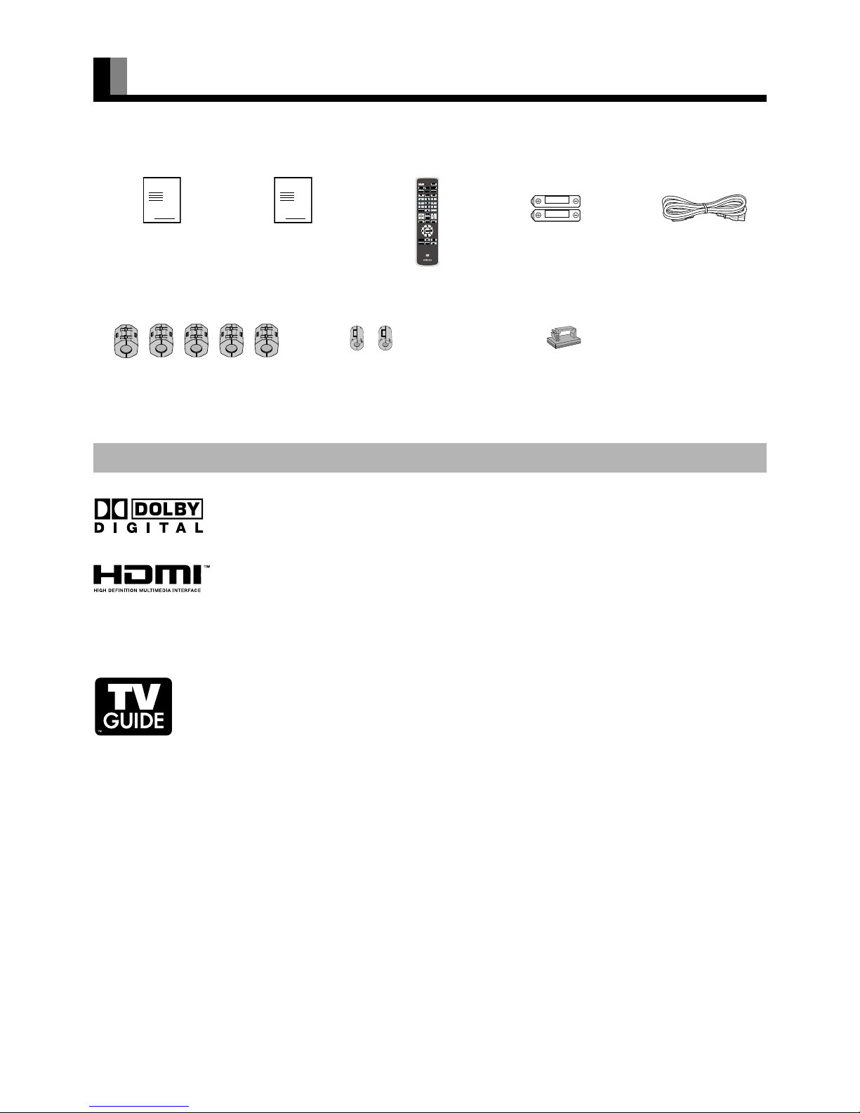
ACCESSORIES
Dolby Digital
Manufactured under license from Dolby Laboratories. "Dolby" and the double-D symbol are trademarks of
Dolby Laboratories.
HDMI (High-Definition Multimedia Interface)
HDMI , the HDMI logo and High-Definition Multimedia Interface are trademarks or registered trademarks of
HDMI licensing LLC.
CableCARD
TM
CableCARDTM is a trademark of Cable Television Laboratories, Inc.
TV Guide On Screen
TM
In the United States, TV Guide and other related marks are registered marks of Gemstar-TV Guide International,
Inc. and/or one of its affiliates. In Canada, TV Guide is a registered mark of Transcontinental Inc., and is used
under license by Gemstar-TV Guide International, Inc.
The TV Guide On Screen system is manufactured under license from Gemstar-TV Guide International, Inc. and/
or one of its affiliates.
The TV Guide On Screen system is protected by one or more of the following United States patents 4,908,713;
6,498,895; 6,850,693; 6,396,546; 5,940,073; 6,239,794 to Gemstar-TV Guide International, Inc. and/or its
subsidiaries.
Gemstar-TV Guide International Inc. and/or its related affiliates are not in any way liable for the accuracy or
availability of the program schedule information or other data in the TV Guide On Screen system and cannot
guarantee service availability in your area. In no event shall Gemstar-TV Guide International, Inc. and/or its
related affiliates be liable for any damages in connection with the accuracy or availability of the program
schedule information or other data in the TV Guide On Screen system.
This product used Software licensed from Monotype Imaging Inc.
TRADEMARK INFORMATION
غ Large ferrite core (5)
(for power cord, S-Video cable,
HDMI cable and RS-232C cable)
غ Small ferrite core (2)
(for external speaker cable)
غ Remote Control غ AA Battery (2)
غ Safety Precautions غ This manual غ Power Cord
See P. E-6 for the
installation procedure.
See P. E-6 for the
installation procedure.
(for 50" / 65" model)
غ Cable clamper (1)
(for external speaker cable)
See P. E-6 for the
installation procedure.
(for 50" model)
Note
• Cables for connecting the display to external equipment are not supplied. Contact your dealer for more information on these supporting products.
• The pictures and diagrams in this manual are meant to complement the explanations and may differ slightly from the actual items.
Page 5
E-5
EnglishDeutschEspañolFrançaisItalianoPortuguês
ᣣᧄ⺆
Póññêèé
፩ၭ
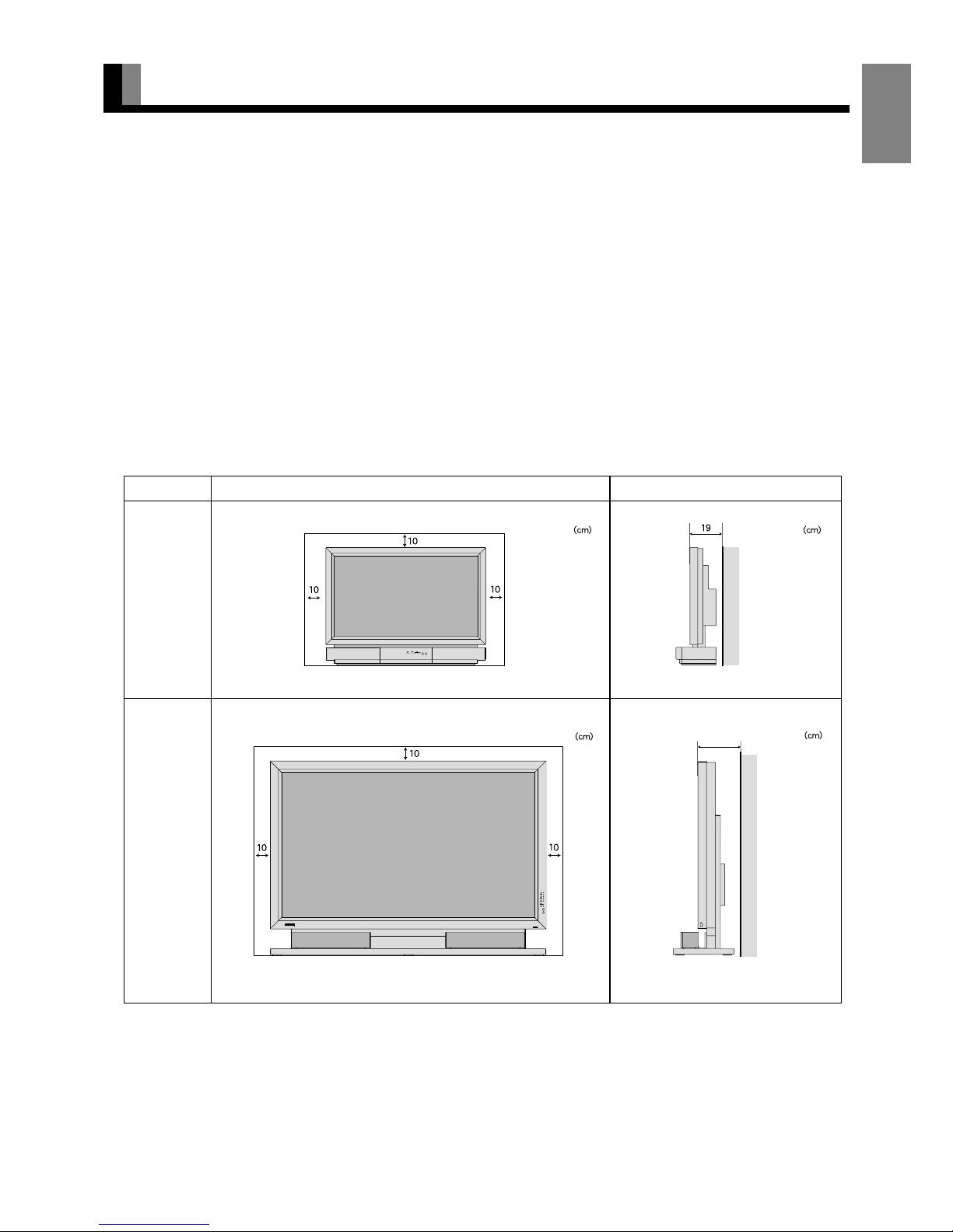
INSTALLATION
To prevent the display's internal components from overheating, make sure that the display is installed in a well-ventilated location.
Be sure to use the optional stand, or the other mounting unit when installing the display. Also, be sure that your dealer performs the
installation.
See the appropriate instruction manual for additional information on the mounting hardware you select.
Use the diagram below to determine how much space is needed to ensure proper heat radiation. This is a minimum space requirement;
therefore, provide at least as much space as indicated below.
* Make sure that the display is installed in a location where the temperature can be maintained between 0°C and 40°C (between 32°F and
104°F)
* Never attempt to tilt the display sideways or backward.
* To prevent the power and other cables from being accidentally pulled, make sure that they run along the wall or through corners.
* To prevent accidents and ensure safety in the event of an earthquake, secure the display to prevent it from tipping over.
* When placing with the display surface down, lay the body on a flat surface covered with a thick towel, etc. so as not to scratch the
display surface. Also be careful that the display does not tip over. Don’t place with the back facing down, because there are projections
on the back. (For 50” / 65” model)
Display Section
Upper
Right
Lower
Left
Front Side
Wall
Upper
Right
Lower
Left
Wall
37” model
50” model
65” model
20 (for 50" )
21 (for 65" )
Note
• For models other than 37” model, speaker is optional.
• See P. E-57 for details on the options.
• The external view is meant to be a representation of the actual unit and is not to scale; therefore, it may differ from the actual shape and size of the
product.
• Due to the fragile and highly precise equipment, it is very important to pack properly before transportation using only the packing materials
provided.
• Cables for connecting the display to external equipment are not supplied. Contact your dealer for more information on these supporting products.
Page 6
E-6
INSTALLATION (Continued)
There is the danger of the display toppling over and causing an injury due to an earthquake or other unexpected shock. To use the display
with peace of mind, take toppling prevention measures. Install stout hooks (commercial product) to the threaded holes at the back of the
display and fasten the hooks to a TV stand or pillar with strong wire (commercial product).
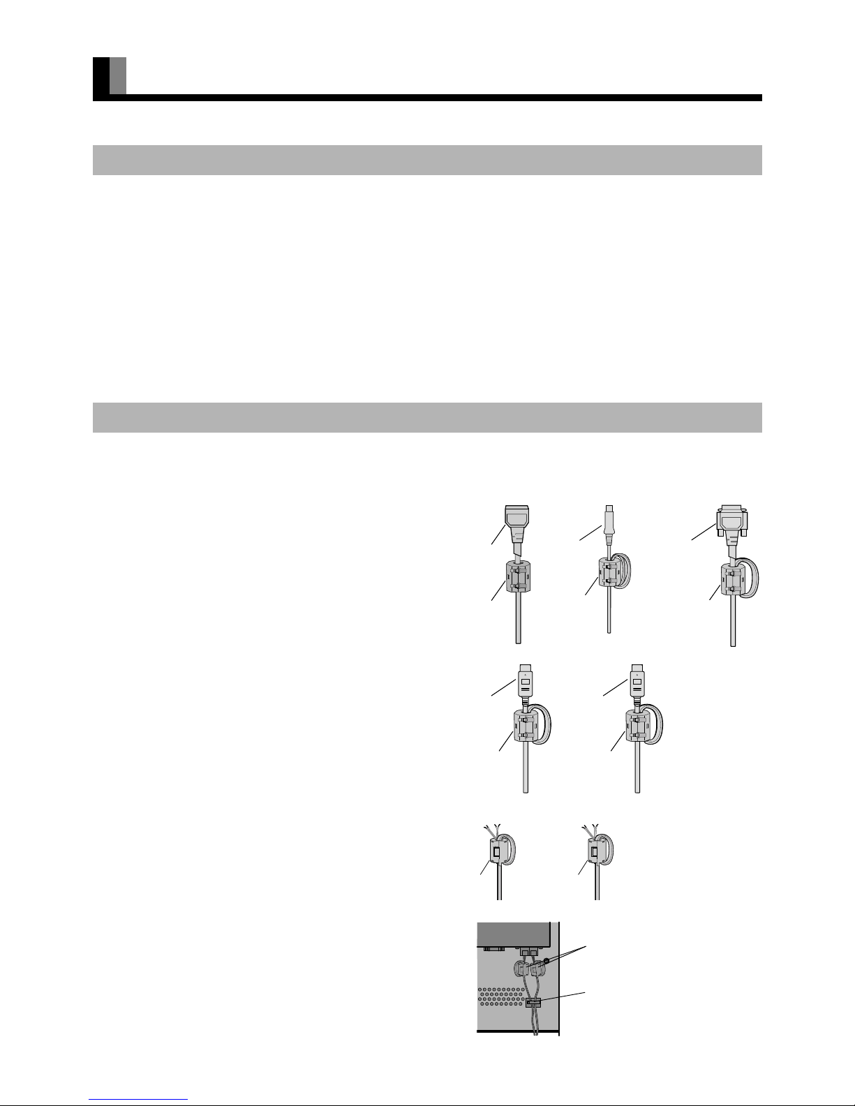
• The ferrite cores are used to reduce noise. Attach them correctly as shown in the following illustrations.
5 large ferrite cores
When connecting the cord to the power input terminal, RS232C
terminal, S-video input terminal, and HDMI input terminal (2),
attach one of these ferrite cores to the cord and the cable near
the terminal.
2 small ferrite cores (for 50" / 65" model)
When connecting a cable to the external speaker output terminal
attach one of these ferrite cores to the cable near the terminal.
1 cable clamper (for 50" model)
Fix the speaker cable using a cable clamper as shown in the
figure at right.
(Do not fix the cable clamper above the air ventilation holes.)
TOPPLING PREVENTION
ATTACHING THE FERRITE CORES
Power Cord
RS232C Cable
Ferrite Core
Ferrite Core
Ferrite Core
S-video
cable
HDMI Cord
Ferrite Core
HDMI Cord
Ferrite Core
Ferrite Core Ferrite Core
Ferrite Core
Cable Clamper
Page 7
E-7
EnglishDeutschEspañolFrançaisItalianoPortuguês
ᣣᧄ⺆
Póññêèé
፩ၭ
PART NAMES AND FUNCTIONS
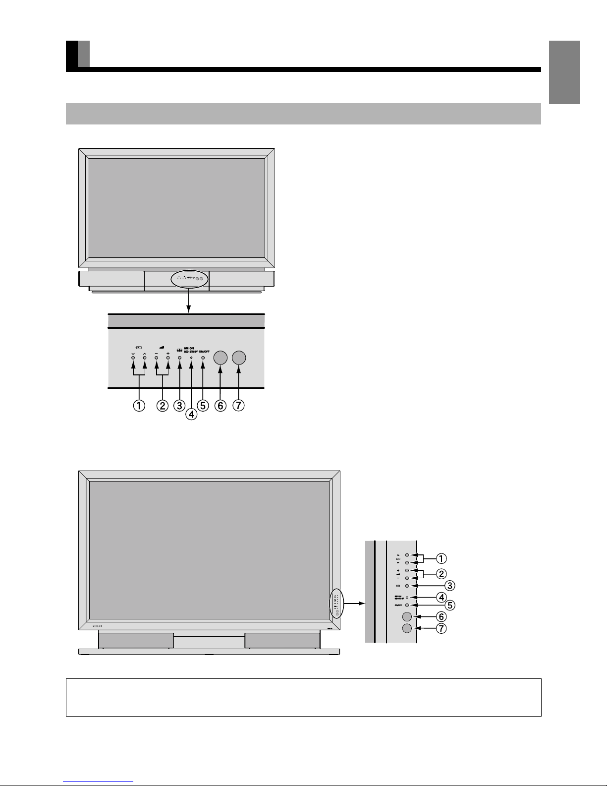
DISPLAY SECTION – FRONT
Input mode selection button
Switches the input modes (Video mode, RGB mode, IEEE1394
mode and TV mode).
Volume button
Adjusts the sound volume.
Wide screen selection button
Switches the screen over to a desired wide screen.
Power indicator lamp
This lamp shows the state of the power supply.
Lit (red): Standby state
Lit (green): Power ON state
Flashing (red or green): Malfunction (Flashes differently
depending on the type of
malfunction.)
ON/OFF button
Turns the power "ON" and "OFF (standby state)".
Remote control signal receiver
Receives the signals from the remote control.
Ambient Sensor
Detects the brightness of ambient light.
It is important not to obstruct it for full functionality of the feature.
Warning
If the power indicator lamp flashes red or green, this signifies that the display has developed a problem. When this happens, be sure to remove the
power plug from the receptacle and contact your dealer. In this circumstance, leaving the display power ON can result in fire or electric shock.
37” model
50" / 65" model
Note
• The pictures and diagrams in this manual are meant to complement the explanations and may differ slightly from the actual items.
Page 8
E-8
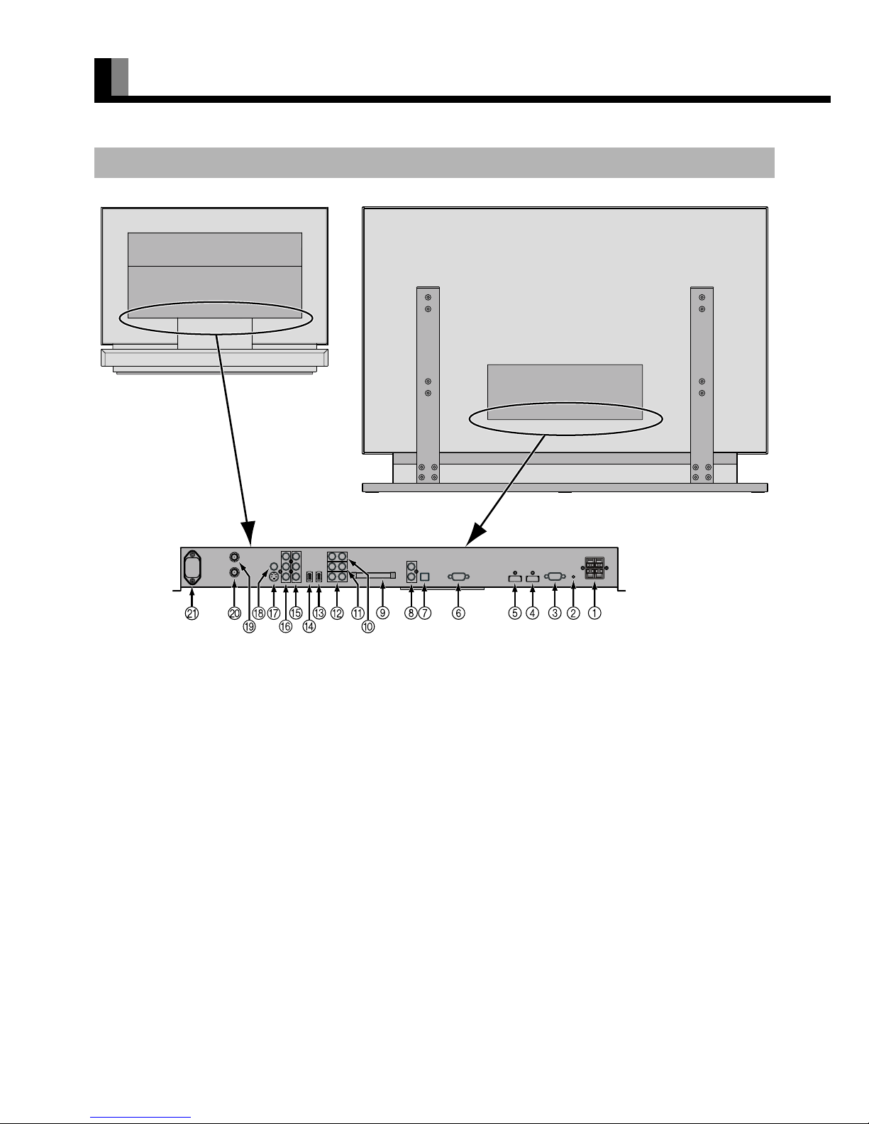
PART NAMES AND FUNCTIONS (Continued)
External speaker output terminal (EXT. SP) for 50" / 65" model
Connect these terminals to the speakers.
When connecting a cable, attach a ferrite core to the cable. (See P. E-6.)
* For details, see the speaker unit installation manual.
Expansion terminal (EXP. PORT)
Currently, this terminal is not functional and is provided to accommodate future technology enhancements. Do not connect any cable to
this terminal.
RS-232C terminal (RS-232C)
This terminal is provided for you to control the display directly from a PC. Connect it to the RS-232C terminal on the PC.
When connecting a cable, attach a ferrite core to the cable. (See P. E-6.)
Video6 input terminal (VIDEO6 INPUT/HDMI)
Connect this terminal to the HDMI output terminal of DVD recorder/player or other video source.
When connecting a cable, attach a ferrite core to the cable. (See P. E-6.)
Video5 input terminal (VIDEO5 INPUT/HDMI)
Connect this terminal to the HDMI output terminal of DVD recorder/player or other video source.
When connecting a cable, attach a ferrite core to the cable. (See P. E-6.)
RGB1 input terminal (RGB1 INPUT/mD-sub)
Connect this terminal to the output terminal of a PC, set-top box, game, etc.
Digital audio output terminal (AUDIO OUTPUT DIGITAL)
Connect this terminal to the digital audio input terminal of the audio amplifier.
DISPLAY SECTION – BACK
Back of the display
(for 37” model)
Back of the display
(for 50" / 65" model)
Page 9

E-9
EnglishDeutschEspañolFrançaisItalianoPortuguês
ᣣᧄ⺆
Póññêèé
፩ၭ
Analog audio output terminal (AUDIO OUTPUT ANALOG)
Connect this terminal to the analog audio input terminal of the audio amplifier.
CABLE CARD slot (CABLE CARD)
To receive cable TV programs insert the card supplied from cable TV provider. (See P. E-15.)
Audio1 input terminal (AUDIO1 INPUT)
Connect this terminal to the audio output terminal of VCR or PC, etc.
Audio2 input terminal (AUDIO2 INPUT)
Connect this terminal to the audio output terminal of VCR or PC, etc.
Audio3 input terminal (AUDIO3 INPUT)
Connect this terminal to the audio output terminal of VCR or PC, etc.
" Link1394 terminal (1394)
Connect this terminal to a STB, DV camera, AVHDD, etc. by IEEE1394 interface.
# Link1394 terminal (1394)
Connect this terminal to a STB, DV camera, AVHDD, etc. by IEEE1394 interface.
$ Video4 input terminal (VIDEO4 INPUT/Y P
B PR)
Connect this terminal to the Component Video Output terminal of DVD recorder/player or satellite receiver.
% Video3 input terminal (VIDEO3 INPUT/Y P
B PR)
Connect this terminal to the Component Video Output terminal of DVD recorder/player or satellite receiver.
& Video2 input terminal (VIDEO2 INPUT/S-Video)
Connect this terminal to the S-Video output terminal of VCR or DVD recorder/player.
When connecting a cable, attach a ferrite core to the cable. (See P. E-6.)
' Video1 input terminal (VIDEO1 INPUT/VIDEO)
Connect this terminal to the Video output terminal of VCR or DVD recorder/player.
( VHF/UHF antenna input terminal (ANTENNA)
Connect this terminal to the VHF/UHF antenna signal.
) Cable TV antenna input terminal (CABLE)
Connect this terminal to the cable TV antenna signal.
* Power input terminal
Connect this terminal to the power cord supplied with the display.
When connecting a cable, attach a ferrite core to the cable. (See P. E-6.)
Note
• The pictures and diagrams in this manual are meant to complement the explanations and may differ slightly from the actual items.
Page 10
E-10
PART NAMES AND FUNCTIONS (Continued)
For details, see page Î.
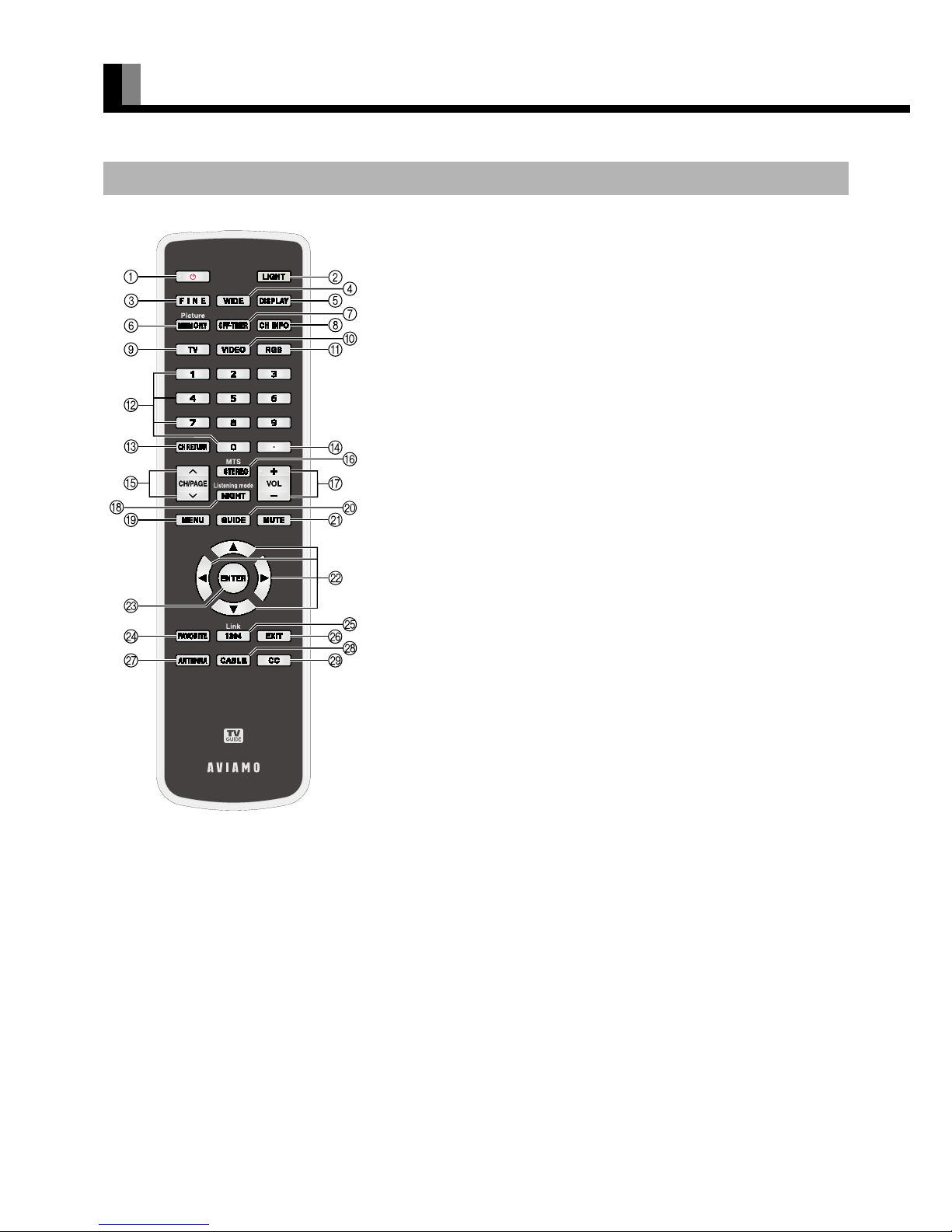
REMOTE CONTROL
(POWER button) Î E-19
Press to switch between Power On and Standby.
[ (LIGHT button)
Press to light the buttons of the remote control.
When no operation is performed, lighting of the buttons goes off after 8 seconds.
4 (FINE mode button) Î E-22
Press to switch the Picture Mode.
(WIDE button) Î E-22
Press to switch to a desired wide screen.
3 (DISPLAY button) Î E-22
Press to display the channel, input mode, and screen size status.
The status is displayed for about five seconds.
5 (PICTURE MEMORY button) Î E-22, E-30
Press to recall the Picture Memory.
7 (OFF-TIMER button) Î E-22
Press to specify the length of time until the power automatically turns off (stand-by
state).
_ (INFORMATION button) Î E-21
Press to display the current channel information.
(TV button) Î E-20
Press to watch TV broadcasting.
(VIDEO button) Î E-20
Press to switch from VIDEO1 through VIDEO6.
(RGB button) Î E-20
Press to select RGB1.
㨪 , ! (Number buttons) Î E-20
Press to directly select a channel.
"
: (CHANNEL RETURN button) Î E-20
Press to return to the previous channel, Video mode, or RGB mode.
$
/ or 0 (Channel Up/Down buttons) Î E-20
Press to select the preset programs.
%
G (MTS/STEREO button) Î E-21
Press to select the audio mode such as MTS (Multi-channel TV Sound) or stereo.
&
1 or 2 (VOLUME buttons) Î E-19
Press to adjust the volume control.
Note
• When the buttons are lighted by pressing [, the battery life is shortened.
Page 11

E-11
EnglishDeutschEspañolFrançaisItalianoPortuguês
ᣣᧄ⺆
Póññêèé
፩ၭ
' (NIGHT mode button) Î E-21
When viewing at night, lowers the volume to an easy-listening value.
(
; (MENU button) Î E-24–E-56
Press to display or hide the menu screen.
Use for Picture or Audio adjustment.
)
` (GUIDE button) Î E-21, E-45–E-56
Displays and hides the TV Guide On Screen.
*
- (MUTE button) Î E-19
Press to temporarily mute the audio. To restore the sound, press the button again.
Instead, the
1 or 2 button can also be pressed.
+
E, F, C, or D (Adjustment buttons) Î E-24–E-56
Use these buttons to select the item or adjust the value of the on screen menu.
,
< (ENTER button) Î E-24–E-56
Press to confirm the setting you made with the Adjustment buttons.
-
^ (FAVORITE button) Î E-21
Displays your favorite channel.
.
(Link1394 button) Î E-20, E-43–E-44
Selects and controls the devices connected by IEEE1394 interface.
/
J (EXIT button) Î E-25, E-40
Use to exit from a menu screen.
0
(ANTENNA button) Î E-20
Press to switch to the signal input of ANTENNA terminal.
1
(CABLE button) Î E-20
Press to switch to the signal input of CABLE terminal.
2
(CLOSED CAPTION button) Î E-21
Press to display the closed captions.
Page 12
E-12
USING THE REMOTE CONTROL
• To prevent malfunction, do not apply any form of severe shock to the remote control.
• To prevent malfunction or deformation, do not allow the remote control to become wet, and keep it away from hot surfaces or heating
equipment.
• Do not clean the remote control using a cloth dampened in a volatile solvent, such as benzene or thinner.
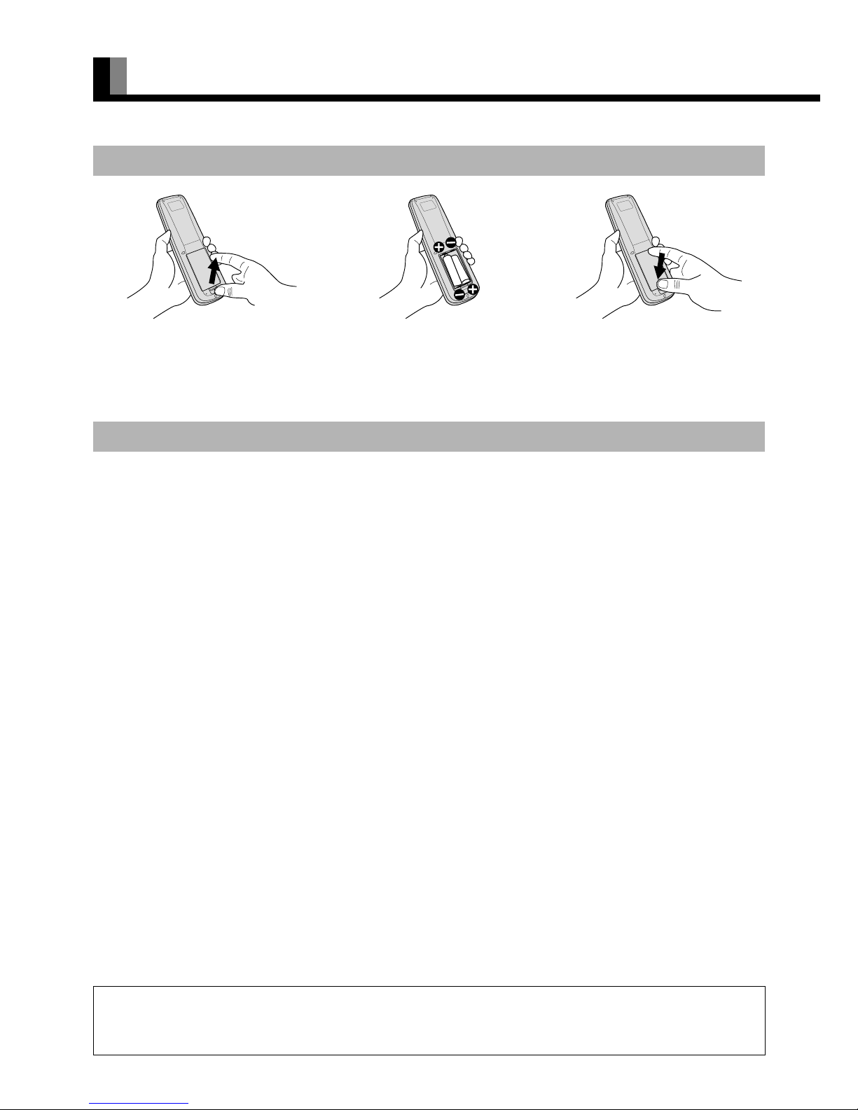
PUTTING BATTERIES IN THE REMOTE CONTROL
(1) Push the lever and lift and remove the
cover in the arrow direction.
(2) Place two AA batteries in the remote
control. Make sure that the batteries are
properly oriented.
(3) Close the cover until it snaps into place.
PRECAUTIONS
CAUTION
It is very important to use replacement batteries of the same type as the originally used. Do not use rechargeable batteries (Ni-Cd, etc.).
When disposing of used batteries, please comply with governmental regulations or environmental public institution’s rules that apply in your country/
area.
Page 13
E-13
EnglishDeutschEspañolFrançaisItalianoPortuguês
ᣣᧄ⺆
Póññêèé
፩ၭ
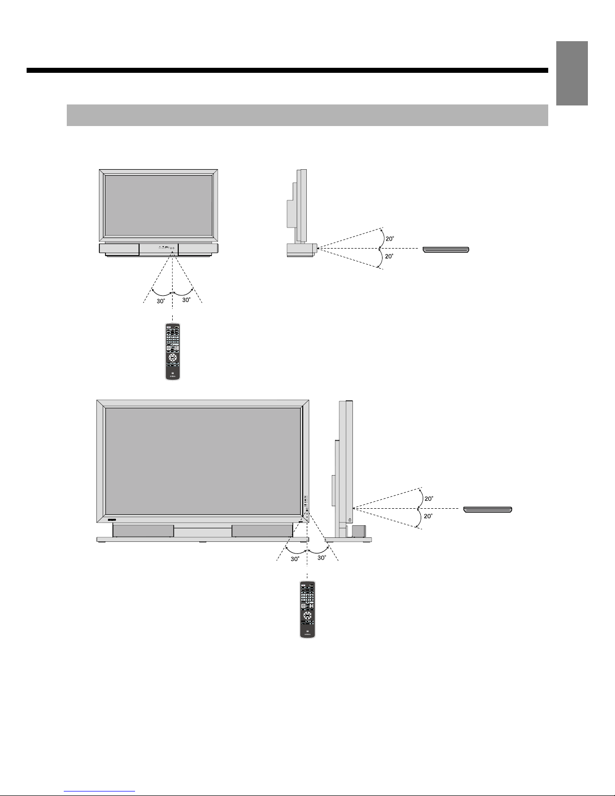
When using the remote control, be sure to point it directly at the display’s signal receiver.
Make sure that there are no obstacles between the remote control and the display’s signal receiver.
EFFECTIVE RANGE FOR THE REMOTE CONTROL
Left
Display – front Display – side
Upper
Lower
Right
5 m (Front)
Remote Control
Remote Control
Left
Display – front
Display – side
Upper
Lower
Right
5 m (Front)
Remote Control
Remote Control
37” model
50" / 65" model
Note
• When the battery is consumed, the remote control will not operate correctly. Replace the batteries with new batteries. (When replacing the battery,
replace both batteries with new batteries of the same type as the original batteries.)
• The remote control may not function properly if a high-frequency fluorescent lamp or the like is used. In this case, move the lamp or use the remote
control from a different position.
Page 14
E-14
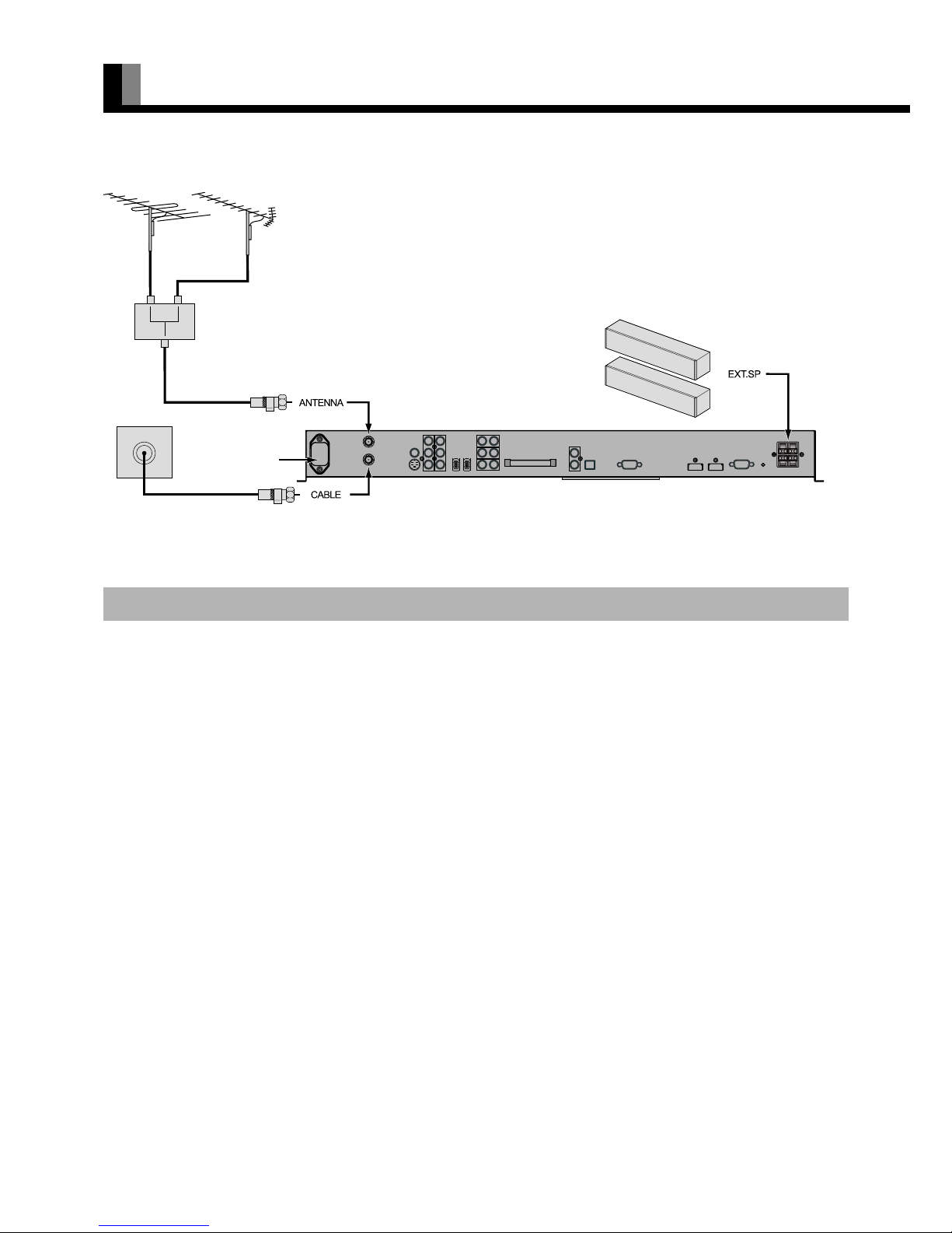
BASIC CONNECTION AND PREPARATION OF THE SYSTEM
• Before this display can be operated for the first time, the connections and settings below must be completed.
* For best reception (of terrestrial signal), an outdoor antenna (OTA) is recommended.
1. Connect a terrestrial antenna (VHF/UHF) to ANTENNA. (Connect the antenna by referring to the figure above.)
* When a terrestrial antenna is not connected, proceed as described below.
2. Connect the cable TV cable to CABLE.
Connect the cable by referring to the figure above.
3. Connect the speakers. (For details, see the manual of optional Speaker Unit. for 50" / 65" model)
4. Connect external equipment such as a DVD Player. (For details, see "EXAMPLE OF CONNECTING EXTERNAL
EQUIPMENT" P. E-18.)
• The subsequent steps of the setting procedure are different between cable TV programs and terrestrial TV programs.
CONNECTIONS TO THE DISPLAY
VHF/UHF antenna
Back of the display
To the receptacle for
3-prong power plug
with grounding
(for 50" / 65"
model)
Rear panel terminal
Page 15
E-15
EnglishDeutschEspañolFrançaisItalianoPortuguês
ᣣᧄ⺆
Póññêèé
፩ၭ
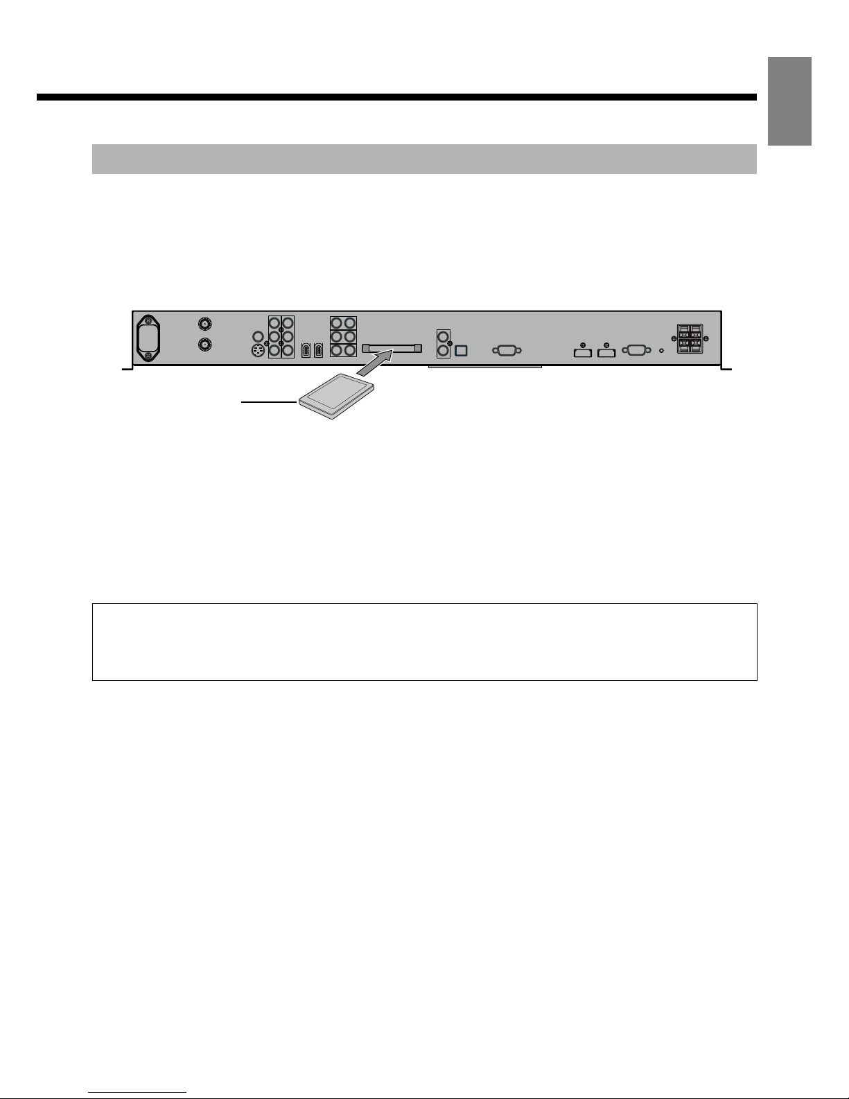
* To watch cable TV broadcasts, sign up with a cable-TV provider before installing and connecting the display. For details, contact the
cable-TV provider.
5. Insert the CableCARD.
The cable-TV provider supplies the CableCARD after you sign up for service. (Make sure the cable company knows you are requesting or
upgrading to CableCARD service.)
Insert the CableCARD into the slot shown in the figure below before turning on the power for the first time after the purchase of the
display.
* Be sure to insert the CableCARD designated by the cable-TV provider.
6. Connect the power cord coming from the display to the outlet, and turn on the power supply. For further information,
observe the content of "Power On" (P. E-19) .
7. Press
to select the TV mode.
8. Press
to select signal of CABLE.
9. Select a desired program.
10. Press
` to initialize TV Guide On Screen system.
(For details, see "INITIALIZING TV GUIDE ON SCREEN SYSTEM" P. E-45.)
TO RECEIVE CABLE TV PROGRAMS (WITH CableCARD)
About CableCARD
• The display enables you to watch cable TV broadcasts without the set top box.
• To watch cable TV broadcasts, you need to sign up with a cable-TV provider in your region.
• The cable-TV provider supplies the CableCARD in response to the contract. You can watch cable TV broadcasts by inserting the CableCARD into
the CABLE CARD slot in the display.
Upper side of the card
Note
• Be sure to use only the CableCARD supplied by the cable-TV provider.
Do not insert PCMCIA card other than CableCARD into the CableCARD slot.
• Slowly push in the designated CableCARD until it is locked.
• Insertion of an undesignated card may damage the CableCARD slot.
• Pictures will not display unless CABLE is connected.
• It may take time to obtain channel information.
• When a CableCARD has been inserted into the display, the set's power consumption increases slightly. - in both the standby state and power on state.
• When the power cable is disconnected or broadcasts cannot be received (antenna was disconnected, etc.) after the cable card was inserted/set, it may
be impossible to receive data from the cable TV provider. In this case, it may become impossible to view the contracted programs even if the power
is turned on again. When this state occurred, please contact the cable TV provider.
• When upgrading the CableCARD firmware, do not remove the power cable or the CableCARD. The CableCARD may be destroyed. The
CableCARD firmware may be upgraded in either the standby state or power on state. For checking during upgrading, check the messages on the
screen in the power on state.
• If you are using a CableCARD and the display is not operating properly, try disconnecting and reconnecting the power cable and turning the display
power on.
• The CableCARD may be hot; remove with caution.
Page 16

E-16
BASIC CONNECTION AND PREPARATION OF THE SYSTEM (Continued)
(Continued from page E-14)
* To watch cable TV broadcasts, sign up with a cable-TV provider before installing and connecting the display. For details, contact the
cable-TV provider.
5. Connect the display's power cord to the outlet, and turn on the power. (For details, see "Power ON" (P. E-19).)
6. Press
to select the TV mode.
7. Press
to select signal of CABLE.
8. Perform Auto Scan. For details, see "TV SETTING (TV MENU) - Channel Setting - Auto Scan" (P. E-41).
9. Select a desired program.
10. Press
` to initialize TV Guide On Screen system.
(For details, see "INITIALIZING TV GUIDE ON SCREEN SYSTEM" P. E-45.)
(Continued from page E-14)
5. Connect the display's power cord to the outlet, and turn on the power. (For details, see "Power ON" (P. E-19).)
6. Press to select the TV mode.
7. Press
to select signal of ANTENNA.
8. Perform Auto Scan. For details, see "TV SETTING (TV MENU) - Channel Setting - Auto Scan" (P. E-41).
9. Select a desired program.
10. Press
` to initialize TV Guide On Screen system.
(For details, see "INITIALIZING TV GUIDE ON SCREEN SYSTEM" P. E-45.)
TO RECEIVE CABLE TV PROGRAMS (WITHOUT CableCARD)
TO RECEIVE TERRESTRIAL TV PROGRAMS
Page 17
E-17
EnglishDeutschEspañolFrançaisItalianoPortuguês
ᣣᧄ⺆
Póññêèé
፩ၭ
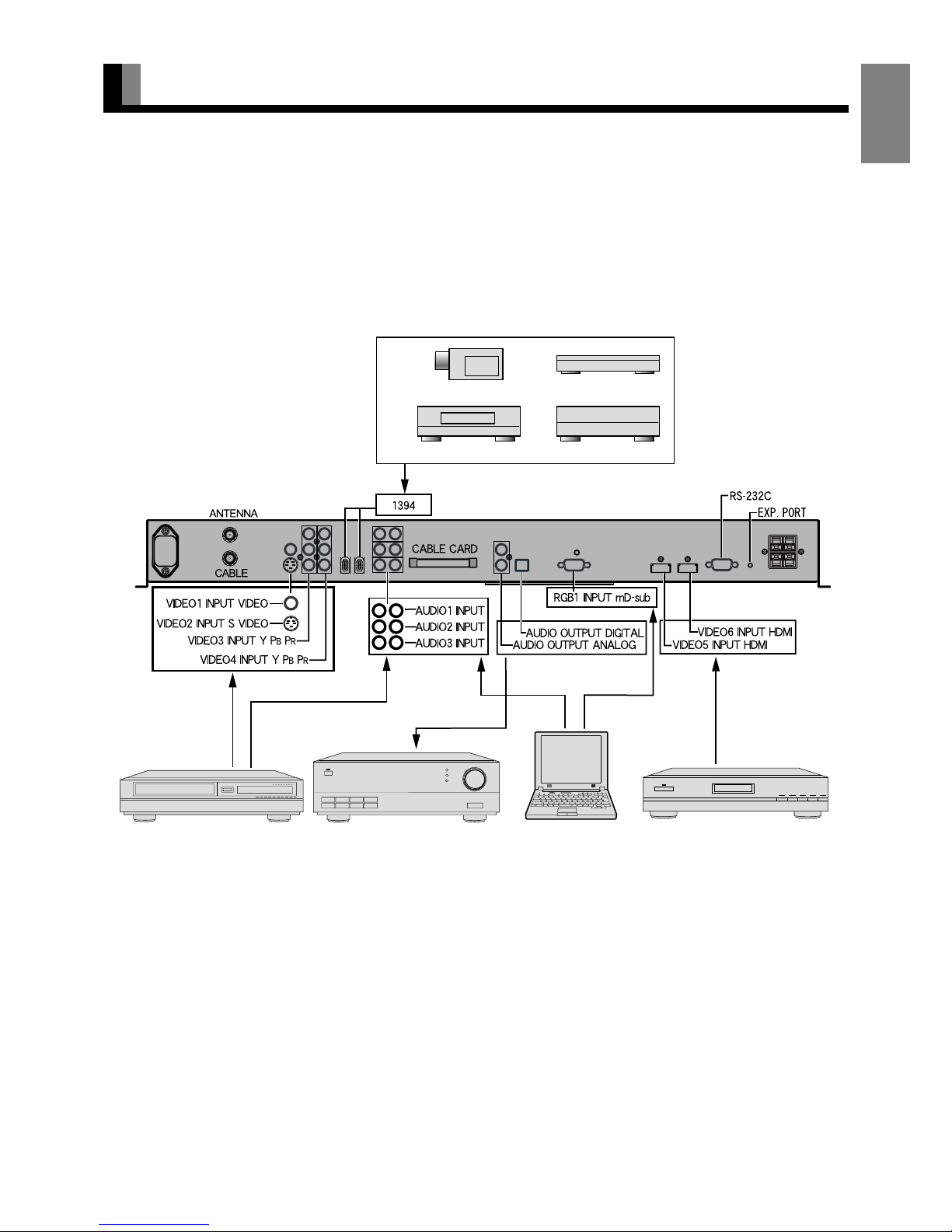
CONNECTING TO EXTERNAL EQUIPMENT
• Before external equipment is connected, all the power cables must be unplugged.
• For the terminal names, see P. E-8.
• If the equipment to be connected has an HDMI output terminal and component video output terminal, one or the other of the terminals -not
both- should be connected.
• Refer to instruction manual for the equipment to be connected.
• There are three audio inputs (HDMI audio excluded). Set them according to Audio Input on P. E-38.
• To receive cable-TV programs, contact a desired cable-TV provider.
Back of the display
Video output
S-Video output
Component Video
output
External equipment (e.g., VCR,
DVD recorder/player, or digital
tuner)
Audio amplifier
Personal computer
HDMI-compatible external
equipment (e.g., DVD player)
Audio output
Digital audio input
Analog audio input
RGB output (Analog)
HDMI output
Audio output
DV camera
STB
DVHS
AVHDD
See P. E-44 for "PRECAUTIONS RELATED TO
CONNECTION OF IEEE1394 DEVICES".
Page 18
E-18
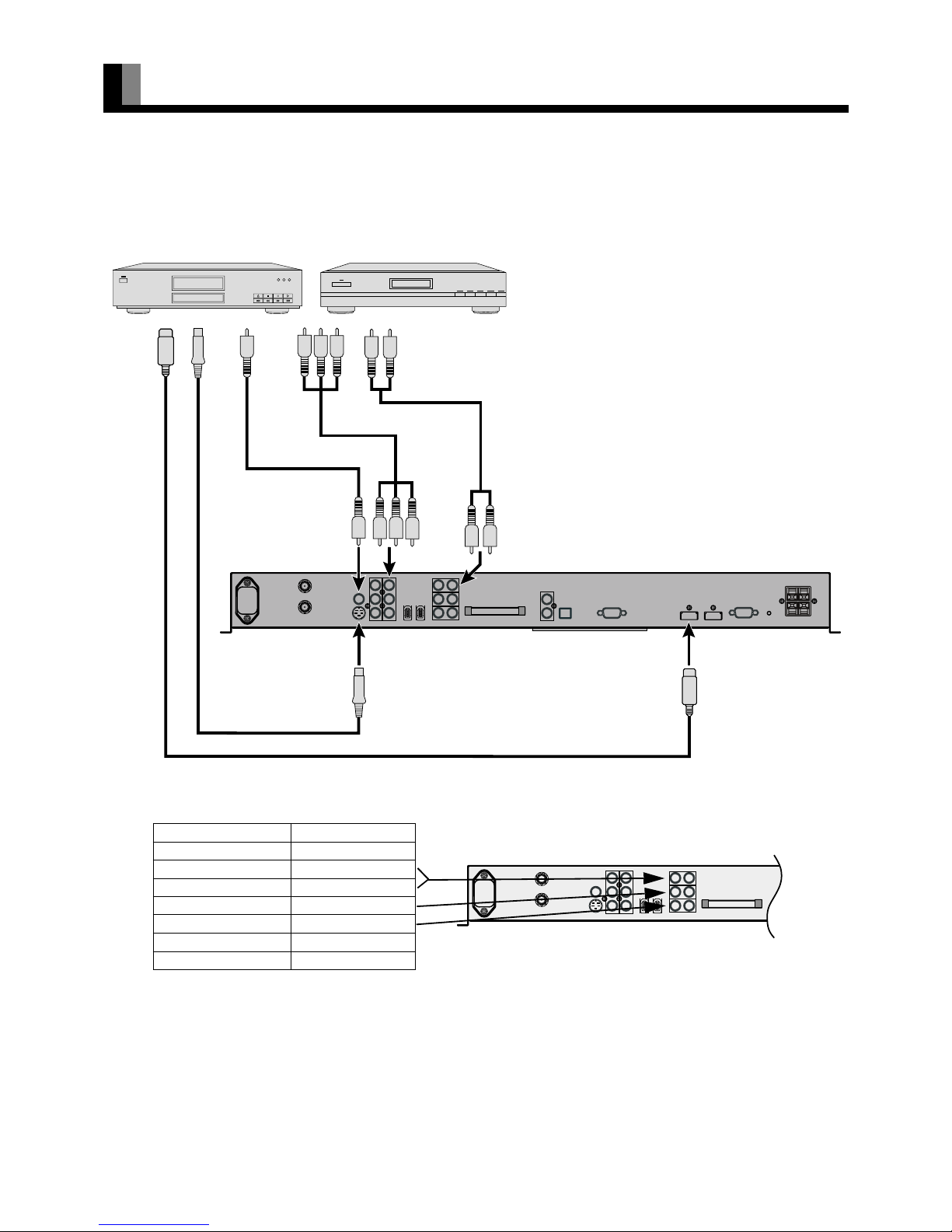
EXAMPLE OF CONNECTING EXTERNAL EQUIPMENT
• Connect the Video signal cable to the HDMI input terminal, Component Video input terminal, S-Video input terminal, or the Video input
terminal.
• If the equipment to be connected is equipped with HDMI out put terminal and Component Video output terminal, it is recommended to
connect to only one of the terminals. If the HDMI output is connected, an Audio signal cable does not need to be connected.
• The table below shows the settings of Audio inputs. (Factory setting)
* For changing of Audio input settings, see Audio Input on P. E-38.
To Video output
To S-video
output
To Audio output
To Audio input
To Video input
To S-video input
To Component
Video output
To
Component
Video input
To HDMI input
To HDMI
output
Back of the display
DVD or VCR
Video input Audio input
RGB1(D-sub) No Audio
Video1(Video) Audio1
Video2(S-video) Audio1
Video3(Component Video)
Audio2
Video4(Component Video)
Audio3
Video5(HDMI) Audio4(HDMI)
Video6(HDMI) Audio5(HDMI)
Note
• The cable for connection to external equipment is not supplied. Purchase a commercially available cable.
• Unplug the power cord from the AC outlet before you connect external equipment.
• Carefully check the terminals for position and type before making any connections.
• Loose connectors can result in picture or color problems. Make sure that all connectors are securely inserted into their terminals.
• You should also refer to the instructions for the equipment to be connected.
Page 19

E-19
EnglishDeutschEspañolFrançaisItalianoPortuguês
ᣣᧄ⺆
Póññêèé
፩ၭ
BASIC OPERATIONS
Turn "ON" the power.
1
Press .
The power is turned on, and the power lamp changes
from "Red" to "Green."
Select the Video, RGB, TV or IEEE1394
mode to enable ordinary operation.
* Make sure that the power cord is connected to a 3-
core receptacle in advance. (See P. E-14 of "BASIC
CONNECTION AND PREPARATION OF THE
SYSTEM")
Turn "OFF" the power (the display placed in standby
state).
1
Press when the power is "ON."
The power lamp changes from "Green" to "Red" and the
display becomes the standby state.
The volume can be adjusted.
To increase the volume, press
1.
To decrease the volume, press 2 .
* Note that the volume level remains stored even when
you turn "OFF" the power.
* An audio signal from an audio output terminal
(AUDIO OUTPUT DIGITAL or AUDIO OUTPUT
ANALOG) does not change.
The sound can be temporarily muted.
Press -.
The sound is muted.
To restore the original sound volume, press the button
again.
The volume can also be restored by pressing
1 or
2 .
* An audio signal from an audio output terminal
(AUDIO OUTPUT DIGITAL or AUDIO OUTPUT
ANALOG) does not change.
Power ON
Power OFF (standby state)
VOL (Volume)
MUTE
View when 1 or 2 is pressed
Note
• If the operation is not executed for about 60 seconds, the menu disappears.
• Some functions are not available depending on the state or condition of use.
Page 20

E-20
WATCHING TV, VIDEO, RGB AND IEEE1394 MODE
Select the TV mode to watch TV programs.
1
Press .
Terrestrial TV programs or cable TV programs are
available. The last program No. that you watched is
received.
2
Press to watch terrestrial
programs. Press
to watch
cable TV programs.
3
Select a desired Program No.
There are two methods to select a Program No.
㨯 Using - , or !
㨯 Using / or 0
* For more information, see P. E-14 "BASIC
CONNECTION AND PREPARATION OF THE
SYSTEM".
The program can be toggled back to a previous channel,
video input or RGB input.
Press :.
The program reverts to the channel viewed immediately
before the present channel. If the previous content was
from another video input, the video mode reverts to that
input.
Terrestrial or cable TV broadcastings can be selected.
Press .
The ANTENNA signal is selected.
Press .
The CABLE signal is selected.
Select the video mode to watch pictures through video
inputs.
Press .
Each time this button is pressed, the video input mode is
switched to the next one. The video input mode can
also be switched directly by pressing
and then
the number button on the remote control.
VIDEO1: Video
VIDEO2: S-video
VIDEO3: Component video
VIDEO4: Component video
VIDEO5: HDMI
VIDEO6: HDMI
* For the settings of input terminals, see "EXAMPLE
OF CONNECTING EXTERNAL EQUIPMENT"
(P. E-18) and "Audio Input" (P. E-38).
Select the RGB mode to watch pictures through the
RGB input.
Press .
The RGB input mode is selected.
* For the settings of input terminals, see "EXAMPLE
OF CONNECTING EXTERNAL EQUIPMENT"
(P. E-18), "Selecting the settings of D-SUB Input
terminal" (P. E-34), and "Audio Input" (P. E-38).
The connected devices can be controlled from the
display. (Control may be impossible, depending on the
device.)
Press .
The devices connected to the 1394 terminals are
displayed on the screen.
Select each device, and press
<.
* For more information, see P. E-43 "IEEE1394
SETTING".
TV
CH RETURN
ANTENNA/CABLE
VIDEO
RGB
Link 1394 (IEEE1394)
• Auto Lock is provided for parents to determine that TV programs and video pictures not good for their children are blocked.
• Restrictions on the watching of TV programs can be placed by channel, age, and program category.
• For details, see "Auto Lock (Parental Lock) Setting" on P. E-36.
About Auto Lock (Parental Lock)
Page 21

E-21
EnglishDeutschEspañolFrançaisItalianoPortuguês
ᣣᧄ⺆
Póññêèé
፩ၭ
CONVENIENT TV AND VIDEO FUNCTIONS
Favorite channels set by Favorite Ch of the menu can be
viewed.
Press ^.
Recalls an already registered channel.
Each time
^ is pressed, the set switches to the
next registered channel.
* See P. E-42 for how to set "Favorite Ch".
Displays TV Guide On Screen.
Press ` .
When ` is pressed again, the TV Guide On
Screen goes off.
* For more information, see "INITIALIZING TV
GUIDE ON SCREEN
TM
SYSTEM" (P. E-45) ,
"USING TV GUIDE ON SCREEN
TM
SYSTEM"
(P. E-47).
* When received the program without TV Guide On
Screen system, the information is not displayed in the
menu even if the GUIDE key is pressed.
Switches closed caption service.
Press .
Closed caption service is switched as shown below.
• Analog closed caption service
$Off$CC1$CC2$CC3$CC4$
TXT1$TXT2$TXT3$TXT4$
• Digital closed caption service
$Off$CS1$CS2$CS3$CS4$
CS5$CS6$CC1$CC2$CC3$
CC4$TXT1$TXT2$TXT3$TXT4$
* See “CC Service SETTING” (P. E-34) for the setting
of digital closed caption service setting.
* To proceed to the next service, press while
the closed caption program name is being displayed.
The audio mode is switched.
Press G.
Each time this button is pressed, the audio mode is
switched.
The switching varies depending on the broadcasting
contents.
* The switching method is determined by the program
you are watching.
* The available language is determined by the program
you are watching.
* If a stereo broadcast is hard to hear due to poor
reception, change to Mono mode.
* Monaural sound is presented when SAP mode is
selected.
Displays the information (channel No., TV station
name, program title, Rating, etc.) for the channel
currently being viewed.
Press _.
When _ is pressed again, the display goes off.
When the NIGHT mode is used when watching TV,
even low volume sounds can be heard clearly. This
function is convenient when watching TV at night.
Press .
Each time this button is pressed, the setting changes as
follows.
$Normal$Night$
[Normal]: Normal sound.
[Night]: Volume is lowered without changing the
sound quality. The volume of sudden loud
sounds, etc. is also suppressed.
FAVORITE (Favorite channels)
GUIDE (TV Guide On Screen)
CC (Closed Caption)
MTS/STEREO
TV-INFO (INFORMATION)
Listening mode NIGHT
Page 22

E-22
OTHER BASIC OPERATIONS
Press 3.
Press this button to display the Program No., input
mode, and screen size status.
This function allows you to set the length of time before
the display automatically goes into standby state.
Press 7.
The standby state is placed when the set time has
passed.
Each time the button is pressed, the time setting is
switched as shown below.
$30min.$60min.$90min.$120min.
$Off$
This function switches the picture mode.
Press 4.
Each time the button is pressed, the mode is switched
between the current picture mode and Fine mode.
* See P. E-26 for how to set Picture Mode.
* While you are watching pictures in Fine mode,
pressing the button does not switch the mode.
This function calls pictures which have been adjusted
and registered. This button toggles among eight preset
picture adjustment groups loaded into memory.
Press 5.
Each time the button is pressed, the picture memory is
switched as shown below.
$Memory1$Memory2$Memory3$
Memory4$Memory5$Memory6$
Memory7 $Memory8$
* See P. E-30 for how to set Picture Memory.
This function switches among available picture display
modes.
1
Press .
The currently selected mode will appear.
2
Press to select a desired
display mode.
Each time you press , a different display mode
appears. Here are the display mode sequences.
TV, Video mode (HD signal)
$Wide1$Wide2$True Signal$
TV, Video mode (SD signal)
$Normal$Wide1$Wide2$Zoom1$
Zoom2$
RGB mode
$
Normal$Wide$Zoom
$
* Depending on the type of signal, some aspects may
not be selected.
* See P. E-32 for how to adjust the display size and
position.
* The buttons on the display can also be used for
adjustments and settings.
DISPLAY
OFF TIMER
PICTURE MODE
PICTURE MEMORY
WIDE
Normal mode
Note
• When the WIDE mode is set to "Normal", and pictures are shown for an extended time, a residual image or "burn-in" may be created. The burn-in
may occur at the boundary where the left and right borders of the picture meet the vertical bars. To reduce the chance of "burn-in" when watching in
the "Normal", we recommend you set the "Background" to "Light Gray". (See P. E-39)
• When a residual image was created, it is reduced by using the "White Screen" settings. Note that there may also be cases when it can not be recovered
completely. (See P. E-39)
• A variety of Screen Sizes are available with this display. Remember that if you select a mode with an aspect ratio (ratio of frame width to frame
height) different from that of the TV program or video media, the pictures will appear differently than if you had selected a mode having the same
aspect ratio.
• Showing a movie or similar premium event at a different aspect ratio from its original one at any event site, restaurant, or bar for profit-making
purposes or for a public audience may constitute a copyright infringement.
For films, try to select a mode having the same aspect ratio as the original picture; this enables the director’s original intentions to be preserved.
• See P. E-32 for how to adjust the picture position and size.
Page 23

E-23
EnglishDeutschEspañolFrançaisItalianoPortuguês
ᣣᧄ⺆
Póññêèé
፩ၭ
Normal
Displaying normal size picture (i.e. a 4:3 aspect ratio).
Wide1
• TV / Video mode (SD signal)
Displays natural-looking pictures of standard size on the
wide screen.
• TV / Video mode (HD signal)
Displays Wide size (16:9 aspect ratio) pictures.
Wide2
• TV / Video mode (SD signal)
Ideal for displaying vertically extended pictures such as
anamorphic (squeezed widescreen) pictures.
• TV / Video mode (HD signal)
An HD signal picture displayed in Normal size is displayed
as wide screen with minor image stretching.
Wide
Displays Normal size picture as wide screen.
True Signal
Displays a pure picture without expansion or contraction of the
picture signal. (for 1080i / 1080P signal)
Zoom1/Zoom
Enlarges horizontally extended pictures equally in all
directions to maintain the aspect ratio constant.
Zoom2
Reduces the height of horizontally extended pictures with
captions, without eliminating the caption. Only the height of
pictures is reduced, not the height of the caption.
(Captions may not be easy to read, however, depending on the
picture.)
* The Zoom mode display method may be different,
depending on the input signal.
The following aspect ratios are available.
VHF/UHF broadcasting, BS broadcasting
4:3 aspect ratio
HDTV broadcasting
16:9 aspect ratio
Vista Vision size
1.85:1 aspect ratio
Cinema Scope size
2.35:1 aspect ratio
SCREEN SIZE
Picture of
standard size
Wide1
Vertically
extended picture
Wide2
Picture of Normal
size
Wide2
ASPECT RATIO
Horizontally
extended picture
Zoom1
Horizontally extended
picture with caption
Zoom2
Note
• Depending on the type of signal, some aspects may not be selected.
• You may find dark areas on top and at the bottom of the screen even if you select one of the Zoom modes for media while using the Vista Vision or
Cinema Scope size i.e. sizes frequently used for movie.
Page 24

E-24
ADJUSTMENT MENU
The numbers in parentheses ( ) indicate the reference page numbers.
Display Menu (E-26) PICTURE (E-26) Signal Contrast (E-26)
Drive Contrast (E-26)
Brightness (E-26)
Color (E-26)
Tint (E-26)
Sharpness (E-26)
Ambient Sensor (E-26)
Picture Mode (E-26)
Precision Setting (E-27) Black Level (E-27)
Detail Gradation (E-27)
3D NR (E-27)
CODEC NR (E-27)
Image Enhance (E-27) Image Identify (E-27)
Chroma Transient (E-27)
Color Temp. (E-27)
User Color Temp. (E-27)
Color Tuning (E-28)
Progressive Scan (E-28) 24 Frame Mode (E-28)
30 Frame Mode (E-28)
Jaggies Filter (E-29)
Motion Setting (E-29)
Gamma (E-29) High Point (E-29)
High Point Gain (E-29)
Low Point (E-29)
Low Point Gain (E-29)
ALC Setting (E-29) High Point Level (E-29)
High Point Gain (E-29)
High Point Limit (E-29)
Low Point Level (E-29)
Low Point Gain (E-29)
Low Point Limit (E-29)
Picture Memory (E-30) Load (E-30)
Save (E-30)
Default
AUDIO (E-31) Treble (E-31)
Bass (E-31)
Balance (E-31)
Loudness (E-31)
Sound Mode (E-31)
POSITION/SIZE (E-32) Position (E-32) Horizontal (E-32)
Vertical (E-32)
Size (E-32) Width (E-32)
Height (E-32)
Default
FEATURES (E-33) Adjustment (E-33) Dot Clock (E-33)
Clock Phase (E-33)
Clamp Position (E-33)
Auto Calibration (E-33)
On Screen Menu (E-33) OSD (E-33)
Language (E-33)
Name Select (E-34)
Input Terminal (E-34) D-SUB Input (E-34)
Clock Set (E-34)
CC Service (E-34) Display (E-34)
Digital (E-35) Size (E-35)
Style (E-35)
Text (E-35) Color (E-35)
Opacity (E-35)
Background (E-35) Color (E-35)
Opacity (E-35)
Edge (E-35) Style (E-35)
Color (E-35)
Auto Lock (E-36)
Parental Ctrl By Level
(E-36)
Parental Ctrl By Ch
(E-37)
New Password (E-37)
Others (E-38) Auto Off-NO SIG. (E-38) Time (E-38)
Background (E-38)
Audio Input (E-38)
Digital Audio Format (E-38)
Screen Orbiter (E-38) Mode/Time (E-38)
Moving Area (E-38)
Direct Setting (E-39)
Code Setting (E-39)
White Screen (E-39)
Background (E-39)
Information (E-39)
FACTORY DEFAULT
(E-40)
TV Menu (E-41) Channel Setting (E-41) Auto Scan (E-41)
Channel Edit (E-41)
Favorite Ch (E-42)
Multi Ch Audio
(E-42)
Audio Language (E-42)
Fact Ch Reset (E-42)
CableCARD (E-42)
Emergency Alert (E-42)
IEEE 1394 (E-43) Standby Mode (E-43)
Note
• Some functions are not available depending on the state or condition of use.
Page 25

E-25
EnglishDeutschEspañolFrançaisItalianoPortuguês
ᣣᧄ⺆
Póññêèé
፩ၭ
BASIC PROCEDURES OF ADJUSTMENT MENU
• Shown below is the basic procedure used to change the
options on the ADJUSTMENT MENU. (Ex.: Adjusting tint
setting (Tint))
• Selecting the adjustment mode for adjustment or setting.
(The items to be adjusted or set are stored for each
adjustment mode.)
1
Press ; .
The main menu screen will appear.
2
PressC or D to select "Display
Menu" and press
F or <.
The "Display Menu" appears.
3
Press C or D to select "PICTURE"
and press
F or <.
Each time you press C or D, one of the available
menus appears in the following sequence:
PICTURE < AUDIO < POSITION/SIZE <
FEATURES < FACTORY DEFAULT
The "PICTURE" menu screen will appear.
4
Press C or D to select "Tint".
5
Press F or <, and press E or F to
change Tint values.
F: More greenish colors
E: More purplish colors
6
Press < to store.
7
Press ; or J when you finish.
* Repeat steps 3, 4, 5 and 6 when you wish to make
changes to other options.
* Select "Default", press
<, select "YES" and press
<. The PICTURE items are changed back to the
default settings available when the display was
purchased.
* Press
; or J to halt the operation in
progress.
"Display Menu"
selected in the main menu
screen
"
PICTURE" selected in the main menu
screen
"
Tint" selected in the PICTURE Menu
screen
"Tint" adjustment screen
Note
• If the operation is not executed for about 60 seconds, the menu disappears.
• Some functions are not available depending on the state or condition of use.
• The adjustment range varies according to the display signals. Make adjustments to your preferred picture quality within the adjustment range.
• Depending on the type of signal, it may not be possible to make some of the settings or adjustments.
Page 26

E-26
ADJUSTING TO A DESIRED PICTURE (PICTURE MENU)
• Picture-related items can be set and adjusted in the Picture
Adjustment Screen. See BASIC PROCEDURES OF
ADJUSTMENT MENU on page E-25 for the basic
procedures.
"Signal Contrast" can be adjusted.
Press
F to increase contrast.
Press
E to reduce contrast.
Press
< to store.
"Drive Contrast" can be adjusted.
Press
F to raise the display’s luminance level, and increase the
contrast.
Press
E to lower the display’s luminance level, and reduce the
contrast.
Press
< to store.
* If Ambient Sensor is ON, the change made by this
adjustment may be difficult to be recognized in too bright or
dark a place.
* When the temperature inside the product is high, changes
when this adjustment was made may be difficult to
comprehend.
"Brightness" can be adjusted.
Press
F to increase the brightness.
Press
E to reduce the brightness.
Press
< to store.
"Color" can be adjusted.
Press
F to darken the color.
Press
E to lighten the color.
Press
< to store.
"Tint" can be adjusted.
Press
F to change the tint to a more greenish color.
Press
E to change the tint to a more purplish color.
Press
< to store.
"Sharpness" can be adjusted.
Press
F to sharpen the Sharpness.
Press
E to soften the Sharpness.
Press
< to store.
"Ambient Sensor" can be set.
Automatically adjusts the picture quality to an optimized level
that matches the brightness of the ambient light.
Each time
E or F is pressed, the setting is switched.
< On < Off <
Press < to store.
"Picture Mode" can be set.
Each time you press
E or F , the available choices appear in
the following sequence.
< Natural < Fine < Effective < Conventional < Still <
Press
< to store.
Signal Contrast
Drive Contrast
Brightness
Color
Tint
Sharpness
Ambient Sensor
Picture Mode
Natural Enables you to watch pictures with
natural color tones and high picture
clarity. This mode is suitable for
watching movies or TV.
Fine Best for watching movies in darkened
rooms.
Effective Best for watching TV in bright
environments.
Conventional Displays a screen approximating that of a
conventional TV screen.
Still Suitable for watching static images such
as computer or still camera images.
Page 27

E-27
EnglishDeutschEspañolFrançaisItalianoPortuguês
ᣣᧄ⺆
Póññêèé
፩ၭ
Even more advanced picture quality adjustments can be made
as required.
Press
F to strengthen the reproduction of black. (Provides a
picture quality with deep blacks.)
Press
E to weaken the reproduction of black.
Press
< to store.
Corrects the gradation of the light and dark areas of the picture.
Each time
E or F is pressed, the setting is switched.
< On < Off <
Press < to store.
This enables noise reduction processing with respect to the
input signal noise level (reduces screen flicker for more
comfortable viewing).
Each time you press E or F, the available choices appear in the
following sequence.
< Off < Min. < Mid. <
Max.
<
Press < to store.
This enables noise reduction processing of mosquito noise or
block noise generated when digital picture signals are recorded
or replayed.
Each time you press E or F, the available choices appear in the
following sequence.
< Off < Min. < Mid. <
Max.
<
Press < to store.
This performs detailed image quality settings.
• Image Identify (RGB)
This function discerns between the natural image display
section and the text display section, and performs correction to
enable an optimized display for each.
Each time
E or F is pressed, the setting is switched.
< On < Off <
Press < to store.
• Chroma Transient
This function corrects the color contours.
Each time
E or F is pressed, the setting is switched.
< On < Off <
Press
< to store.
Use
E or F to specify a desired color temperature. Each time
you press
E or F, one of the available choices appears in the
following sequence:
< -3500K < ... < Std. < ... < +3500K < User <
[–3500K]: More reddish colors
[+3500K]: More bluish colors
[User]: User Color Temp. setup
Press
< to store.
Use
C or D to select Red, Green, or Blue, and adjust the
color temp. for each.
Press
F: to strengthen the selected color.
Press E: to weaken the selected color.
Press < to store.
Precision Setting
Black Level
Detail Gradation
3D NR
CODEC NR
Precision Setting Selection Screen
Image Enhance
Color Temp.
User Color Temp.
Note
• If the operation is not executed for about 60 seconds, the menu disappears.
• Some functions are not available depending on the state or condition of use.
• The adjustment range varies according to the display signals. Make adjustments to your preferred picture quality within the adjustment range.
• Depending on the type of signal, it may not be possible to make some of the settings or adjustments.
Page 28

E-28
ADJUSTING TO A DESIRED PICTURE (PICTURE MENU) (Continued)
This enables correction with respect to specific color hues
within the image.
Independent correction of the hue of skin colors, blue skies,
and so on, enables a more brilliant display.
(1) Use E, F, C, or D to select the item you want to
adjust.
When
< is pressed, the value to be changed blinks.
(2) Use
E or F to make the adjustment.
The adjustment contents can be checked at the screen
displayed at the Custom side.
(3) When
< is pressed, the set data are stored and the
product exits from the input mode.
* When
; is pressed without pressing <, the
product exits from the input mode without storing the
data.
[R (Reddish color)]
Color, Tint, R Gain, G Gain, and B Gain correction is
performed within the range from magenta to yellow, centered
about red.
[G (Greenish color)]
Color, Tint, R Gain, G Gain, and B Gain correction is
performed within the range from yellow to cyan, centered
about green.
[B (Bluish color)]
Color, Tint, R Gain, G Gain, and B Gain correction is
performed within the range from cyan to magenta, centered
about blue.
[r (targeting red)]
Corrects the Color and Tint for red.
[y (targeting yellow)]
Corrects the Color and Tint for yellow.
[g (targeting green)]
Corrects the Color and Tint for green.
[c (targeting cyan)]
Corrects the Color and Tint for cyan.
[b (targeting blue)]
Corrects the Color and Tint for blue.
[m (targeting magenta)]
Corrects the Color and Tint for magenta.
[w (targeting white)]
Corrects the R Gain, G Gain, and B Gain for white.
This sets the conversion processing of interlace signals to
block receive signals.
• 24 Frame Mode
This function enables the optimized display of movies, etc.
with 24 frames/second signals.
Each time
E or F is pressed, the setting is switched.
< Auto < Off <
Press < to store.
• 30 Frame Mode
This function enables the optimized display of movies, etc.
with 30 frames/second signals.
Each time
E or F is pressed, the setting is switched.
< Auto < Off <
Press < to store.
Color Tuning
Color Tuning Settings Screen
Progressive Scan
Progressive Scan Settings Screen
Note
• If the operation is not executed for about 60 seconds, the menu disappears.
• Some functions are not available depending on the state or condition of use.
• The adjustment range varies according to the display signals. Make adjustments to your preferred picture quality within the adjustment range.
• Depending on the type of signal, it may not be possible to make some of the settings or adjustments.
Page 29

E-29
EnglishDeutschEspañolFrançaisItalianoPortuguês
ᣣᧄ⺆
Póññêèé
፩ၭ
• Jaggies Filter
This function alleviates the phenomenon where jagged
diagonal lines can be seen when interlace signals are input,
thus enabling a smoother motion picture display.
Each time
E or F is pressed, the setting is switched.
< Auto < Off <
Press
< to store.
• Motion Setting
The detecting sensitivity for motion picture is set.
The response of the picture processing is valued in the motion
picture priority setting.
Press
F: to specify still picture priority.
Press
E: to specify motion picture priority.
Press
< to store.
You can create your favorite image by fine tuning the
brightness.
• High Point
In a bright image scene, sets the point where the brightness is
to be adjusted.
Press
E or F to set the point where the brightness is to be
adjusted.
Press
< to store.
• High Point Gain
Fine tunes the brightness of the point set by High Point.
Press
E to be darker.
Press
F to be brighter.
Press
< to store.
• Low Point
In a dark image scene, sets the point where the brightness is to
be adjusted.
Press
E or F to set the point where the brightness is to be
adjusted.
Press
< to store.
• Low Point Gain
Fine tunes the brightness of the point set by Low Point.
Press E to be darker.
Press F to be brighter.
Press < to store.
• This function allows setting of the screen to your favorite
luminance matched to the ambient brightness.
• The ALC Setting function operates when the ambient sensor
is turned on. (See "Ambient Sensor" on P. E-26.)
• High Point Level
Sets the upper limit value of the ambient brightness detected by
the ambient sensor.
Press
E to lower the upper limit value.
Press F to raise the upper limit value.
Press < to store.
• High Point Gain
Sets the upper limit value of the screen luminance corresponding to the brightness detected by the ambient sensor in a
bright environment.
Press
E to lower the upper limit value.
Press F to raise the upper limit value.
Press < to store.
• High Point Limit
Limits control of the screen luminance corresponding to the
ambient sensor when the value detected by the ambient sensor
exceeds the High Point Level and High Point Gain.
Each time E or F is pressed, the setting is switched.
[On]: Limit operates
[Off]: Limit does not operate
Press
< to store.
• Low Point Level
Sets the lower limit value of the ambient brightness detected by
the ambient sensor.
Press
E to lower the lower limit value.
Press F to raise the lower limit value.
Press < to store.
• Low Point Gain
Sets the lower limit value of the screen luminance corresponding to the brightness detected by the ambient sensor in a dark
environment.
Press
E to lower the lower limit value.
Press F to raise the lower limit value.
Press < to store.
• Low Point Limit
Limits control of the screen luminance corresponding to the
ambient sensor when the value detected by the ambient sensor
is lower than the Low Point Level and Low Point Gain.
Each time E or F is pressed, the setting is switched.
[On]: Limit operates
[Off]: Limit does not operate
Press
< to store.
Gamma
ALC Setting
Page 30

E-30
ADJUSTING TO A DESIRED PICTURE (PICTURE MENU) (Continued)
Eight groups of picture adjustment settings can be stored,
enabling you to quickly switch to your desired group of
settings for watching program.
[Load]: When memory 1~8 is selected using
C or D,
the image adjustment value becomes the value registered in
selected memory 1~8.
[Save]: Use
C or D to select Memory 1 - 8. If < is
pressed, the current picture adjustment values are stored to the
selected Memory.
Picture Memory
Picture Memory Selection Screen
"Load" Selection Screen
"Save" Selection Screen
Page 31

E-31
EnglishDeutschEspañolFrançaisItalianoPortuguês
ᣣᧄ⺆
Póññêèé
፩ၭ
ADJUSTING TO DESIRED AUDIO (AUDIO MENU)
• You can make changes to all audio adjustment options in the
AUDIO Menu. See Page E-25 for the basic procedures.
• The changes you make will be stored for the selected input
mode. Therefore, you need to select a desired input mode
before making any changes.
Press
E or F to make adjustments.
F: Stronger treble
E: Weaker treble
Press < to store.
Press
E or F to make adjustments.
F: Stronger bass
E: Weaker bass
Press
< to store.
Press
E or F to make adjustments.
F: Shifts the volume balance towards the right.
E: Shifts the volume balance towards the left.
Press < to store.
Corrects the balance between bass and treble for easy listening
even with weak volume.
Each time you press
E or F, one of the available choices
appears in the following sequence:
< Off < Min. < Mid. < Max. <
Press
< to store.
Sets the sound field.
Each time
E or F is pressed, the setting is switched.
< Flat < Standard < Voice < Surround <
[Flat]: Reproduces the sound input signal naturally.
Mild sound reproduction is realized.
[Standard]: Listening-fatigue-free, placid sound
reproduction is realized by suitable
equalizing (sound quality adjustment).
[Voice]: Increases the sound clarity. Announcements,
dialogue, etc. become easy to hear.
[Surround]: Sound image is spread left, right, up, and
down. Sound with the realistic sensation of a
movie, etc. is enjoyed.
Press < to store.
Treble
Bass
Balance
AUDIO Menu screen
Loudness
Sound Mode
Note
• If the operation is not executed for about 60 seconds, the menu disappears.
• An audio signal from an audio output terminal (AUDIO OUTPUT DIGITAL or AUDIO OUTPUT ANALOG) does not change.
• AUDIO menu will not be displayed when "No Audio" is selected. (See P. E-38)
Page 32

E-32
ADJUSTING SCREEN POSITION AND SIZE (POSITION/SIZE MENU)
• You can make changes to all screen adjustment options in the
POSITION/SIZE Menu.
• See Page E-25 for the basic procedures.
• The changes you make will be stored for the selected input
mode. Therefore, you need to select a desired input mode
before making any changes.
• The adjustment range may vary depending on the input
signal.
Horizontal position (Horizontal)
F: Moves the screen picture to the right.
E: Moves the screen picture to the left.
Vertical position (Vertical)
C: Moves the screen picture up.
D: Moves the screen picture down.
Press
< to store.
Screen width (Width)
F: Increases the width.
E: Reduces the width.
Screen height (Height)
C: Increases the height.
D: Reduces the height.
Press
< to store.
Position
POSITION/SIZE Menu screen
"Position" adjustment screen
Size
"Size" adjustment screen
Note
• Some functions are not available depending on the state or condition of use. (The adjustment screen may also vary slightly.)
• The adjustment range varies according to the display signals. Make adjustments to your preferred picture quality within the adjustment range.
• Depending on the type of signal, it may not be possible to make some of the settings or adjustments.
Page 33

E-33
EnglishDeutschEspañolFrançaisItalianoPortuguês
ᣣᧄ⺆
Póññêèé
፩ၭ
OTHER SETTINGS (FEATURES MENU)
• To adjust or set items such as Adjustment, On Screen Menu,
Input Terminal, and Channel Setting, select "FEATURES"
from the adjustment menu. See P. E-25 for the basic
procedures.
• The items to be adjusted or set are stored for each input
mode. Thus, execute the following operation after selecting
the input mode for the adjustment or setting.
You may find the vertically-striped pattern in pictures,
depending on the clock frequency of your PC's processor.
If you experience blurring, you can obtain a clearer picture by
adjusting the "Dot Clock".
Use
E or F to adjust to minimize vertically-striped pattern in
pictures.
Press
< to store.
Pictures and the outline of letters may blur or flicker as the
clock phase of your PC may be different. In this case, adjust
the clock phase manually. Normally, the "Auto" setting ensures
the optimal value.
Use
C or D to select "Auto" or "Manual".
[Auto]: Makes automatic adjustment.
[Manual]: Makes manual adjustment.
Press E or F to adjust to minimize pictures blur.
Press
< to store.
Adjusts the extremely dark or bright picture. Normally, the
automatic setting ensures the optimal value.
Use
E or F to adjust pictures optimally.
Press
< to store.
Adjusts the dynamic range of picture to the optimum. Execute
while a white screen signal is received.
(1) Select "Execute" and press
<.
(2) Press C or D to select "YES", and press <.
You can use this option to select from following display
indication.
Each time you press
E or F, one of the available choices
appears in the following sequence:
< On (OSD:bright) < On (OSD:dark) <
[On (OSD:bright)]: On-screen information shown in
light color.
[On (OSD:dark)]: On-screen information shown in dark
color.
Press
< to store.
* If the screen picture is too bright, some characters may be
difficult to watch when [On (OSD:dark)] is selected.
You can use this option to select the language displayed on the
screen.
Press
C or D to select your desired language.
English
Español (Spanish)
Français (French)
Press
<.
The menu is displayed in the selected language.
ADJUSTMENT ITEMS
Dot Clock for RGB
Clock Phase for RGB
Clamp Position for RGB, Component Video
Auto Calibration for RGB
ON SCREEN MENU SETTING
OSD
Language
"On Screen Menu" Screen
Note
• If the operation is not executed for about 60 seconds, the menu disappears.
• Some functions are not available depending on the state or condition of use. (The adjustment screen may also vary slightly.)
• The adjustment range varies according to the display signals. Make adjustments to your preferred picture quality within the adjustment range.
• Depending on the type of signal, it may not be possible to make some of the settings or adjustments.
Page 34

E-34
OTHER SETTINGS (FEATURES MENU) (Continued)
You can change the settings for indications for video inputs and
RGB inputs.
RGB input
You can change the settings for indications for the RGB inputs.
Select the desired indication in accordance with the connected
equipment.
Each time
E or F is pressed, the setting is switched.
< RGB1 < PC1 < PC2 < DVD1 < DVD2 < STB <
Satellite < Cable TV <
Press
< to store.
Video input
You can change the settings for indications for the VIDEO
inputs.
Select the desired indication in accordance with the connected
equipment.
Each time
E or F is pressed, the setting is switched. (In the
case of VIDEO1)
< Video1 < DVD1 < DVD2 < VCR1 < VCR2 <
GAME < Camcorder < STB < Satellite < Cable TV <
Press
< to store.
You can use this option to select the signal system it will
receive to D-SUB Input terminal.
(1) Select D-SUB Input and press
<.
D-SUB Input screen appears.
(2) Select the signal system to receive.
Each time you press
E or F, one of the available choices
appears in the following sequence:
< RGB-PC < Decoder <
[RGB-PC]: For using RGB of PC
[Decoder]: For using digital broadcast tuner
(3) Press
< to store.
The date and time can be set.
Press
C or D to select the item, and press E or F to set
it.
Each time
C or D is pressed, the items are selected in the
following sequence:
Year < Month < Day <Hour < Minute <
Time Zone < Daylight Saving
* The display clock has a function which automatically
acquires the time information from TV Guide On Screen
and corrects it to the newest state. Since TV Guide On
Screen is used, always initialize TV Guide On Screen
beforehand.
The closed caption service setting procedure is as follows.
* The Closed Caption Service is available only when current
TV program or video picture has the service information.
* This function does not work in VIDEO5,6 (HDMI).
This function determines whether to turn ON/OFF the closed
caption service.
Press
E or F to switch between the items.
< On < Off <
Press
< to store.
Name Select
Input Terminal SETTING
Selecting the settings of D-SUB Input terminal
"Input Terminal" Screen
Clock Set SETTING
CC (Closed Caption) Service SETTING
Display
"CC Service" Screen
Page 35

E-35
EnglishDeutschEspañolFrançaisItalianoPortuguês
ᣣᧄ⺆
Póññêèé
፩ၭ
This function sets the closed caption service for digital mode.
Settings such as program service, character style, and character
size can be selected using the following functions.
Size
A target character size can be set.
Press
E or F to switch among the items.
< Standard < Large < Small <
Press
< to store.
Style
A target character style can be set.
Press
E or F to switch among the items.
< Default < Styl e1 <Style2 < St yle3 < Style4 <
Style5 < Style6 < Style7 <
Press < to store.
Text
The color and transparency of characters can be set.
Press
C or D to select Color/Opacity.
- Color
Press
E or F to switch among the items.
< Black < White < Red < Green < Blue < Yel low <
Magenta < Cyan <
Press < to store.
-Opacity
Press
E or F to switch among the items.
< Solid < Flashing < Translucent < Transparent <
Press
< to store.
Background
The color of the background and transparency can be set.
Press
C or D to select Color/Opacity.
- Color
Press
E or F to switch among the items.
< Black < White < Red <Green < Blue < Yell ow <
Magenta < Cyan <
Press
< to store.
-Opacity
Press
E or F to switch among the items.
< Solid < Flashing < Translucent < Transparent <
Press
< to store.
Edge
The edge and color of characters can be set.
Press
C or D to select Style/Color.
-Style
Press
E or F to switch among the items.
< None Text Edge < Raised < Depressed < Uniform
< Left Shadow < Right Shadow <
Press < to store.
- Color
Press
E or F to switch among the items.
< Black < White < Red < Green < Blue <Yel lo w <
Magenta < Cyan <
Press
< to store.
Digital
Note
• If the operation is not executed for about 60 seconds, the menu disappears.
• Some functions are not available depending on the state or condition of use.
• The adjustment range varies depending on the display signal. Adjust to a desired picture quality in the allowable adjustment range.
• Setting and adjustment may be disabled depending on the signal type.
Page 36

E-36
OTHER SETTINGS (FEATURES MENU) (Continued)
Auto Lock is provided for the parents to determine that TV
programs and video pictures not good for their children are
blocked.
Restrictions on the watching of TV programs can be placed by
channel, age, and program category.
Sets MPAA system and TV RATING system program viewing
restriction at the television channel and video input.
Select Parental Ctrl By Level by
C or D and press <.
Enter the Password.
(initial value: "
")
Placing restrictions on the watching of TV programs by
channel or age.
Press
E, F, C, or D to select a target item.
Press
< to switch between blocking and unblocking.
Description of MPAA chart symbols
Description of TV RATING symbols
Auto Lock (Parental Lock) SETTING
Parental Ctrl By Level
"Auto Lock" Screen
“Enter Password” Screen
NONE MPAA chart Lock are all cleared.
G For the general audience of all ages
PG
Parental guidance suggested. Some
programs are not good for children.
PG-13
Some programs are not good for children at
age 13 years or younger.
R
Parents' permission required for children at
age 17 years or younger
NC-17 Not for children at age 17 years or younger
X For adults only
NONE TV RATING chart Lock are all cleared.
TV-Y For children of all ages
TV-Y7 For children of at age 7 years or older
TV-G For general audience
TV-PG Parents' permission is required.
TV-14 Firm warning to parents
Program parents would find unsuitable for
children under 14 years of age.
TV-MA For adults only
FV Fantasy Violence
L Adult Language
S Sexual situations
VViolence
D Suggestive Dialogue
Note
About Auto Lock (Parental Lock)
• Auto Lock can be set for TV and video inputs by age and program category.
• The Auto Lock system of the display is compatible with both TV Rating system and MPAA system.
• The Auto Lock system is available for both analog TV broadcastings and digital TV broadcastings.
• Once Auto Lock is set, the display does not show the restricted program (neither pictures nor audio) when receiving it.
• When receiving a program for which Auto Lock is set, the display shows the "Program Blocked" screen. To show the program, enter the password.
All the settings for Auto Lock are reset temporarily when the password is entered. To enable Auto Lock, turn off the power (STANDBY), and then
turn it ON again. Also, when ^ or other operation is performed, or the power is turned on/off, while the "Program Blocked" screen is displayed,
the screen may become blank. Also, when ^ or other operation is performed, or the power is turned on/off, while the "Program Blocked" screen is
displayed, the screen may become blank. In this case, reselect the program you want to watch by pressing / or 0.
• The Auto Lock system is available only for TV broadcastings and video signals (Video mode, S-Video mode and Comp.video(480i) mode) that are
based on the parental lock standard. The Auto Lock feature will work only when a program rating is available.
• This function does not work in VIDEO5,6 (HDMI).
Page 37

E-37
EnglishDeutschEspañolFrançaisItalianoPortuguês
ᣣᧄ⺆
Póññêèé
፩ၭ
Viewing control can be turned on and off for the channel to be
viewed.
Select Parental Ctrl By Level by
C or D and press <.
Enter the Password.
(initial value: "")
A channel listing is displayed.
Press
C or D to select a target item.
Press
E or F to switch between blocking (Lock) and
unblocking (Unlock).
* When a blocked channel is viewed, "Program blocked"
display appears.
Performed when changing the Password.
Select New Password by
C or D and press <.
(1) Enter Old Password by 4-digit number from
to
.
(2) Enter New Password by 4-digit number from
to
.
(3) Enter New Password again.
Memorize by pressing
;.
Password is changed and memorized.
* It is important to note your password for future use.
Parental Ctrl By Ch
"Auto Lock" Screen
“Enter Password” screen
“Parental Ctrl By Ch” Screen
New Password
"Old Password" Screen
Note
• If the operation is not executed for about 60 seconds, the menu disappears.
• Some functions are not available depending on the state or condition of use.
• The adjustment range varies depending on the display signal. Adjust to a desired picture quality in the allowable adjustment range.
• Setting and adjustment may be disabled depending on the signal type.
Page 38

E-38
OTHER SETTINGS (FEATURES MENU) (Continued)
Adjusting the settings so that the standby state automatically
starts up if the display remains in no signal state for an
extended amount of time.
Selecting the background setting to indicate when the display
is in the no signal state.
Time
(1) Press C or D to select the "Time".
(2) Press
E or F to select the amount of time before the
standby state starts.
< Off < 1 min. < 15 min. < 45 min. < 60 min. <
Press
< to store.
* The numerical value is the approximate amount of time
before the standby state starts.
Background
(3) Press C or D to select the "Background".
(4) Press
E or F to select the display background color.
< Black < White <
Press < to store.
* The background color changes to assigned color state
after approximately 20 seconds in the no signal state.
Selecting the available terminals to receive audio from the
input equipment .
(1) Press
C or D to select video input terminal.
(2) Select a related audio input terminal.
Each time you press
E or F, one of the available choices
appears in the following sequence:
< No Audio < Audio1 < Audio2 < • • • • • <
[No Audio]: No audio in the corresponding mode. (No
audio is output even when this video input
mode is selected.)
[Audio 1-3]: Selects Audio 1 through 3 for receiving
audio in the corresponding mode.
[Audio 4-5]: HDMI
* There is also "Audio Input" that cannot be selected.
(3) Press
< to store.
* For the audio input terminals, see "CONNECTING TO
EXTERNAL EQUIPMENT" (P. E-17) and EXAMPLE OF
CONNECTING EXTERNAL EQUIPMENT" (P. E-18).
* AUDIO menu will not be displayed when "No Audio" is
selected.
You can select the audio format for the signal output from
AUDIO OUTPUT DIGITAL terminal.
Switches as below by pressing
E or F.
< PCM < Dolby Digital <
Press
< to store.
* When a program featuring Dolby Digital audio is selected,
the sound comes from the AUDIO OUTPUT DIGITAL
terminal.
* To receive programs available in Dolby Digital sound, set the
"D Audio Format" of the on-screen menu to Dolby Digital.
• Programs that are not available in Dolby Digital sound will
be output in PCM, even if the AUDIO OUTPUT DIGITAL is
set to "Dolby Digital".
You can use this option to move the screen position to
minimize phosphor-induced "burn-in".
Mode/Time
(1) Press C or D to select "Mode/Time".
(2) Select a desired pattern.
Each time you press
E or F, one of the available choices
appears in the following sequence:
< Off < Time < Mode <
[Off]: Disables Screen Orbiter.
[Time]: Moves the pattern approximately every one hour.
[Mode]: Moves the pattern when the power is turned ON
or when you switch between modes.
Moving Area
(3) Press C or D to select "Moving Area".
(4) Press
E or F to select the range for moving the pattern.
Each time you press
E or F, one of the available choices
appears in the following sequence:
< Min. < Std. < Max. <
[Min.]: Pattern moves in small range. (About 5 pixels)
[Std.]: Pattern moves in moderate range. (About 10 pixels)
[Max.]: Pattern moves in wide range. (About 15 pixels)
(5) Press
< to store.
* When the Screen Orbiter function is operated, some
screen contents. at the top, bottom, right or left of the
screen may move offscreen.
SETTING OTHERS
Auto Off-NO SIG.
Audio Input
"Auto Off-NO SIG." selection screen
"Audio Input" settings screen
Digital Audio Format
Screen Orbiter for RGB
Page 39

E-39
EnglishDeutschEspañolFrançaisItalianoPortuguês
ᣣᧄ⺆
Póññêèé
፩ၭ
You can use this option to switch the setting for RGB input
signal.
Each time you press
E or F, one of the available choices
appears in the following sequence:
< Auto < VGA < WVGA < 480P < XGA < WXGA
< SXGA < SXGA+ <
[Auto]: The optimum display is obtained automatically for
input signals.
[Other than Auto]: The optimum resolution setting is
fixed for each signal.
Press < to store.
* In Auto mode, the resolution of VGA, WVGA, 480P, XGA,
WXGA, SXGA and SXGA+ may not be automatically
detected for optimal use.
* Depending on the model or input terminals, some signals
may not be available and therefore, not displayed.
Normally, use this option in Auto mode.
You can use this option to display white over the entire screen
to minimize phosphor burn-in.
Each time you press
E or F, one of the available choices
appears in the following sequence:
< Off < On <
Press
< to store.
When the screen size was set to "Normal", to reduce "burn-in",
the brightness of the part at which left and right images are not
displayed can be set. Normally, we recommend that "Light
Gray" be used.
Each time you press E or F, the settings is switched.
<Black < Dark Gray < Light Gray <
Press
< to store.
* Effective for plasma display.
* Burn-in can still occur if the Normal mode is shown for
extended periods.
Displays system operation status.
Select "Information" and press
<.
The "Information" screen will appear.
[Mode]: The input mode or channel number is displayed
[Freq. Scan Mode]: Frequency scanning
[Input Signal]: Video mode
[Input Sync.]: Sync. Signal type
[Freq.]: Sync. Signal frequency, polarity
[Preset No.]: RGB code number
Direct Setting for RGB
Code Setting for RGB
White Screen
Background
Information
"Information" Screen (example of Video1 mode)
Note
• If the operation is not executed for about 60 seconds, the menu disappears.
• Some functions are not available depending on the state or condition of use.
• The adjustment range varies depending on the display signal. Adjust to a desired picture quality in the allowable adjustment range.
• Setting and adjustment may be disabled depending on the signal type.
Page 40

E-40
INITIALIZATION OF USER ADJUSTMENT VALUE
Using the MENU to restore the values of the factory settings
after adjustments have been made.
1
Press ;.
The main menu screen will appear.
2
Press C or Dto select "Display
Menu" and press
F or <.
3
Press C or D to select "FACTORY
DEFAULT" and press
F or <.
Each time you press C or D, one of the available
menus appears in the following sequence:
PICTURE < AUDIO < POSITION/SIZE <
FEATURES < FACTORY DEFAULT
The "FACTORY DEFAULT" menu screen will appear.
4
Press <.
5
Press C or D to select the "Yes".
• Displays the message prompting you to proceed with
the initialization.
6
Press <.
• The message of having completed the initialization
will be displayed after initializing.
7
Press ; or J when you finish.
"Display Menu" selected in the main
menu screen
"FACTORY DEFAULT" selected in the
main menu screen
Displays the message prompting you to
proceed with the initialization.
Displays the message of having
completed the initialization
Note
• If the operation is not executed for about 60 seconds, the menu disappears.
• The adjustment range varies depending on the display signal. Adjust to a desired picture quality in the allowable adjustment range.
• Setting and adjustment may be disabled depending on the signal type.
• If a new setting is made for Tuner, CC Service, or Auto Lock, it cannot be changed back to the factory default again.
Page 41

E-41
EnglishDeutschEspañolFrançaisItalianoPortuguês
ᣣᧄ⺆
Póññêèé
፩ၭ
TV SETTING (TV MENU)
The tuner setting procedure is as follows:
Press C or D to select a target item below.
Channel Setting < CableCARD < Emergency Alert
Press
F or < to move on to the next step.
Press
C or D to select a target item below.
Auto Scan < Channel Edit < Favorite Ch <
Multi Ch Audio < Audio Language <Fact Ch Reset
Press
F or < to move on to the next step.
Scans the Antenna or Cable and automatically searches for a
receivable channel and enters that channel in the channel
listing.
Use
C or D to select Yes.
When
< is pressed, Auto Scan starts. Auto Program MENU
appears and Auto Scan is performed.
* When Auto Scan is executed after selecting the
"ANTENNA" input mode by pressing
, only the
signals from "ANTENNA" are auto scanned.
* When Auto Scan is executed after selecting the "CABLE"
input mode by pressing , only the signals from
"CABLE" are auto scanned.
This function displays channels scanned by Auto Scan.
When
/ or 0 is operated, the function also determines
whether to select the channel.
Press
C or D to select a target channel.
Press E or F to switch between the items.
< Add < Skip <
[Add]: Selects a channel.
[Skip]: Disables channel selection.
Channel Setting
Auto Scan
"TV Menu" Screen
"Channel Setting" Screen
"Auto Scan" Screen
Channel Edit
"Channel Edit" Screen
Page 42

E-42
TV SETTING (TV MENU) (Continued)
Sets the channel which is displayed when ^ was pressed.
The channel listing registered by Auto Scan appears.
Press
C or Dto select the channel.
Press
E or F to switch.
< Add < Skip <
[Add]: Can be chosen with ^.
[Skip]: Cannot be chosen with ^.
This function selects an audio program available with the
displayed channel.
Press C or D to select a target audio program.
Press
< to determine the audio program.
* The audio language output and the language displayed on the
screen may differ from each other. The language displayed is
dependent on the signal being received from the broadcast
station and therefore does not indicate any problem with the
display itself.
Switches the audio language.
Switch by pressing
E or F.
< English < Spanish < French <
[English]: English audio is output.
[Spanish]: Spanish audio is output.
[French]: French audio is output.
Press < to store.
* When the set audio is not in the broadcast, audio is output in
another language.
This function resets the current channel list to the factory
setting.
Press
C or D to select "YES", and press <.
This function displays information necessary for contacting
your cable-TV provider.
• The information is not displayed unless the CableCARD is
inserted.
When received the messages of Emergency Alert System
(EAS), the display will automatically display them.
This function sets the display switching to the emergency alert
broadcast.
Press
E or F to switch among the items.
< Low < Mid. < High < Max. <
[Low]: Switches to emergency broadcast whenever an
emergency alert is put on the air.
[Mid.]: Switches to medium or higher priority emergency alert.
[High]: Switches to high or higher priority emergency alert.
[Max.]: Switches to maximum priority emergency alert.
Press
< to store.
* If you want to view the Emergency Alert massages at any
time, please set "Emergency Alert" of on-screen display
menu to "Low".
Favorite Ch
Multi Ch Audio
Audio Language
Fact Ch Reset
CableCARD
Emergency Alert
Note
• If the operation is not executed for about 60 seconds, the menu disappears.
• Some functions are not available depending on the state or condition of use.
• The adjustment range varies depending on the display signal. Adjust to a desired picture quality in the allowable adjustment range.
• Setting and adjustment may be disabled depending on the signal type.
Page 43

E-43
EnglishDeutschEspañolFrançaisItalianoPortuguês
ᣣᧄ⺆
Póññêèé
፩ၭ
IEEE1394 SETTING (IEEE1394 MENU)
1
Press ;.
The MENU screen is displayed.
Press C or D and select "IEEE1394", and then
press
F or <.
The Standby Mode is switched each time
E or F is
pressed.
< On < Off <
[On]: Devices connected by IEEE1394 cable can be
linked even when this set’s power is Off
(Standby).
[Off]: When this set’s power is Off (Standby), devices
connected by IEEE1394 cable cannot be linked.
* Depending on the devices to be connected, they may
be linked even when Standby Mode setting is Off.
The connected devices can be controlled from this product.
(Control may be impossible, depending on the device.)
Connect each device to this product by IEEE1394 cable as
shown in the figure below and perform the operations
described below.
Press .
Select each device, and press <.
Connecting to STB and DTV
The signal from the STB or DTV is displayed as shown below.
Thereafter, follow the instructions displayed on the screen.
Connecting to AVHDD
The signal from the AVHDD is displayed as shown below.
Arbitrary operation is possible by operation screen.
The following is an example of the display when recording
listing was selected and the
< was pressed.
Each operation can be performed by choosing and executing
the icons shown below. Depending on the device to be
connected (external equipment), an icon may not be displayed
or the device may be unusable even if an icon is displayed.
The following is an example of the display when a program
was chosen from the recording listing and the Play button was
pressed.
STANDBY MODE SETTING
IEEE1394 CONNECTION AND OPERATION EXAMPLES
IEEE1394 cable
DTV
STB
IEEE1394 device selection screen
IEEE1394 cable
IEEE1394 device selection screen
Operation screen example
Return
Recording program listing
Stop
Play
Pause
Rewind
Fast forward
Rec Pause
Rec Stop
Erase
Device menu
Power on/off
Operation screen example
Page 44

E-44
IEEE1394 SETTING (IEEE1394 MENU) (Continued)
Only TV-GUIDE recording operation is effective.
There are devices which cannot be connected, depending on
the IEEE1394 devices supported
• DVD recorder, personal computer, personal computer
peripheral devices cannot be connected, because the
specifications are different.
• Analog broadcasts cannot be recorded.
• Operation may be erroneous when a DVD recorder, PC
peripheral devices, and other devices not supported by this
product are connected at the same time.
• When used by connecting multiple IEEE1394 devices,
operation may be unstable depending on the use and
interconnection of the connected devices. In this case,
operation may be stabilized by disconnecting unused devices
or by changing the way the devices are connected.
• When too many devices are connected at the same time,
unexpected operation may be performed depending on the
compatibility, etc. between the interconnected devices.
• Do not connect in a loop.
Also IEEE1394 devices with 3 or more branches are not
supported.
Example of usable connection
Example of unusable connection (because it is a
loop connection)
Example of unusable connection (because there
are 3 branch connections)
While using IEEE1394 devices, do not disconnect or connect
the IEEE1394 cord of the connected IEEE1394 devices. Also,
while using this product, do not perform IEEE1394 device
power on/off and other operations. The picture and sound may
be disturbed.
• Some IEEE1394 device cannot relay data when the power of
the device is turned off. In this case, turn on the power of the
device and then connect.
• Only MPEG2 TS and DV are supported. The picture of
contents recorded with other than this product may be
disturbed.
* When this product does not operate normally, reuse it after
turning off the power once.
PRECAUTIONS RELATED TO CONNECTION OF IEEE1394 DEVICES
This product
This product
This product
Note
• If the operation is not executed for about 60 seconds, the menu disappears.
• Some functions are not available depending on the state or condition of use.
Page 45

E-45
EnglishDeutschEspañolFrançaisItalianoPortuguês
ᣣᧄ⺆
Póññêèé
፩ၭ
INITIALIZING TV GUIDE ON SCREENTM SYSTEM
Initialize TV Guide On Screen system.
Perform initialization in accordance with the TV set on-screen menu.
When you use the "TV Guide On Screen" function for the first time, a TV Guide On Screen system Welcome screen will appear.
Perform setup to offer TV program listing and channel lineup for the area where you live.
When
< is pressed, the process advances to the first setup process.
To navigate in the Guide setup screens
Press E, F, C, D to highlight selections
Press < to select the highlight options.
Press _ to display available Help information.
1
Select your Country.
When C, D is used to select the country and < is pressed, a check mark appears next to the selected country. Use F to
highlight "Next" and press
<.
2
Enter ZIP or Postal Code.
Set the ZIP Code or Postal Code of your area by pressing the number keys. Use F to highlight "Next" and press <.
When
C, D is used to choose video source(s) services and < is pressed, a check mark appears next to the selected video
source. Press
F to highlight "Next" and press <.
Identifying Your Location
Selecting Your Broadcast Services
Reminder screen Welcome screen
The above screen is for USA.
Note
Cable Box and Satellite setups are not supported.
Page 46

E-46
INITIALIZING TV GUIDE ON SCREENTM SYSTEM (Continued)
After you have configured all services you selected in Step 2 you are asked to check your settings.
If you select Yes, continue setup process, go to Step 4.
If you select No, repeat setup process, return to Step 1.
The Helpful Information screen appears when you successfully complete Guide setup.
The setup progress screen appears each time you enter the Guide prior to receiving your initial eight days of show listings. To close
the screen press
<.
Checking Setup
Complete Setup
View Setup Progress Screen
Note
In order to begin to receive your listings, power off the TV when not in use. Within 24 hours, you will begin to receive TV show listings. It may take up
to six days to receive the full eight days of initial show listings.
Page 47

E-47
EnglishDeutschEspañolFrançaisItalianoPortuguês
ᣣᧄ⺆
Póññêèé
፩ၭ
USING TV GUIDE ON SCREENTM SYSTEM
About the TV Guide On Screen System
TV Guide On Screen system offers up to 8 days of television shows. Television shows can be easily viewed and recorded by using TV
Guide On Screen system.
The TV Guide On Screen System has the following 5 main services:
• LISTINGS : Displays show listings.
When a title in a show listing is chosen, information for that show is displayed.
Shows with titles in the show listings can be viewed.
Recording and reminder scheduling of shows are possible.
• SEARCH : Shows you want to view can be searched by keyword, category, or alphabetically by title.
• RECORDINGS : Displays a list of previously recorded or currently recording shows.
• SCHEDULE : Lets you review, edit, or delete scheduled recordings and reminders.
• SETUP : System setup, channel display, and default option can be reviewed and modified.
Common precautions
Initialize TV Guide On Screen system before use.
Program video is not displayed if the cable or the antenna is not connected.
If a broadcast does not contain TV Guide On Screen information, TV Guide On Screen information cannot be acquired. Also, it
may take several days to search 8 days worth of show information.
TV Guide On Screen system supports cable television and VHF/UHF television, but does not support satellite broadcasts.
If not actually aired, a show cannot be viewed even if its name is listed in TV Guide On Screen system.
"RECORDINGS" can be used by connecting your product to a recording device having IEEE1394 functions.
(There are also some devices which do not operate even if connected.)
The pictures in this document are typical. The broadcast stations and shows are different, depending on the reception area.
Remote Control Functions of the TV Guide On Screen system
` : Displays or exits TV Guide On Screen.
_ : Displays program information and HELP.
/, 0 : Scrolls the page.
; : Displays various panel menus.
C, D, E, F : Select shows and functions.
< : Executes the selected item(s).
Page 48

E-48
USING TV GUIDE ON SCREENTM SYSTEM (Continued)
Basic Operation
When ` is pressed while watching TV, the TV Guide On Screen "LISTINGS" screen appears.
(When ` is pressed while watching picture through IEEE1394 input, the TV Guide On Screen "LISTINGS" screen appears, too.)
When _ is pressed when the Info icon is displayed, programs, services, or HELP Information is displayed in an Info Box.
Performing operations while viewing the information displayed in the Info Box is convenient.
FEATURE Description
Video Window Displays TV video while the Guide is displayed (can be locked on a single channel or unlocked to
preview channels as you navigate "LISTINGS" and Channel Editor)
Lock/Unlock Icon Indicates the status of the Video Window
Clock Displays the current local time
Service Bar Provides access to the main Guide Services
Current Services Label Indented to identify the current Service screen
Info Box Provides information for a highlighted item
Info Icon Indicates you can press
_ to cycle through the various Info Box sizes or view Help text for a
Service
Info Bar Displays show-specific broadcast information, such as new episode, TV or Movie rating, and show
progress indicator
Ad Location where show- or product-specific information appears
(Menu) Location where on-screen menus appear
Channel Logo & Number Identifies network and channel number
Title Tile Displays show title.
Highlight Indicates an active tile, from which you can set recording, set reminder, display a menu, etc.
Record & Remind Icon Indicates you set a recording or reminder event for the show
HD Icon Identifies shows that are broadcast in HDTV
LISTINGS SCREEN
Page 49

E-49
EnglishDeutschEspañolFrançaisItalianoPortuguês
ᣣᧄ⺆
Póññêèé
፩ၭ
TV Guide On Screen Icons (Examples)
Icon Description
Closed captioning is available
Identifies shows that are broadcast in HDTV
Program is available in stereo
Program is new
TV Rating for the program (example)
Records the show one time
Records the show if the show title appears on any day of the week on the same channel at a similar start time
Records the show if the show title appears on a specific day of the week on the same channel at a similar start time
Records on the specified channel and time every Monday through Friday
Keeps the recording in "TO DO" but does not record until you reset the frequency
Reminds you once for a specific show episode
Reminds you if the show title appears on any day of the week on the same channel at a similar start time
Reminds you if the show title appears on a specific day of the week on the same channel at a similar start time
Reminds you for the specified channel and time every Monday through Friday
Keeps the reminder in "TO DO" but does not remind until you reset the frequency
Page 50

E-50
USING TV GUIDE ON SCREENTM SYSTEM (Continued)
1
When ` is pressed while watching TV, the TV Guide On Screen "LISTINGS" screen
appears.
2
Use E, F, C, D to select the desired title tile (show title) in the program listing.
To view the selected show
Press <.
To view the contents of the selected show and the information for programs which will air later
Press
_.
To set recording and reminder selected shows, or edit, and delete the scheduled show
Press ;. The "Episode Options" menu appears on the left side of the screen. Setting, editing, and deletion are performed
from within this menu.
Use
C, D to choose the item in the "Episode Options" menu you want to execute, and press <.
Episode Options items
LISTINGS
Item Contents
go to Service Bar Highlights "LISTINGS" on the "Service Bar".
watch now /tune to channel Displays the channel being aired or a channel scheduled to be aired.
set recording
When each "Record Options" item is set and
< is pressed, "schedule recording" is highlighted.
Recording of shows can be scheduled by pressing
<again.
set reminder
When each "Remind Options" item is set and
< is pressed, "schedule reminder" is highlighted.
Reminder of shows can be scheduled by pressing
< again.
delete recording Cancels scheduled recording shows.
(Displayed only when a scheduled recording show was chosen.)
edit recording Edits each item of a scheduled recording show.
(Displayed only when a scheduled recording show was chosen.)
delete reminder Cancels scheduled reminder shows.
(Displayed only when scheduled reminder show was chosen.)
edit reminder Edits each item of a scheduled reminder show.
(Displayed only when a scheduled reminder show was chosen.)
Cancel Cancels the "Episode Options" menu.
Page 51

E-51
EnglishDeutschEspañolFrançaisItalianoPortuguês
ᣣᧄ⺆
Póññêèé
፩ၭ
INFORMATION
An ALERT screen is displayed before a scheduled Recording or Reminder program is started. (Default: 1 minute before) When
schedules overlap, use
C, D to choose the program you want to watch and press <.
Setting Listings Options
When LISTINGS is highlighted and ; is pressed, the Listings Options screen appears on the left side of the screen. The
video, channel ID or edit channel function can be performed.
video window : "locked" - video remains on a single channel
"unlocked" - video changes channels as you navigate the grid
When
< is pressed after setting, "done" is highlighted. When < is pressed again, setting is finished.
channel ID : "both" - both channel logo and number are displayed in the grid
"logo" - only channel logo is displayed in the grid
"number" - only channel number is displayed in the grid
When
< is pressed after setting, "done" is highlighted. When < is pressed again, setting is finished.
edit channels : Sets "Change channel display" of the "SETUP". Change the program service that the TV Guide On Screen
uses for any channel. Edit the channels that appear in the TV Guide On Screen, reorder their position in the
grid, change their tune channel, and, if you have more than one program service, specify the service and input
for each channel. You can modify settings directly in the Channel Editor screen.
Shortcuts
In "LISTINGS", use the number keys on your remote control to
- Enter the number of the channel you want to view, or
- Enter the number of hours (or days) you want to jump ahead or back
The Shortcuts menu appears.
Press
D or C to highlight the command you want and press <, or
- If you entered a channel number, press < when the menu appears to jump directly to the channel row.
- If you entered a specific number of hours, press D (hours ahead) or C (hours back) when the menu appears to jump directly
to that time slot.
Page 52

E-52
USING TV GUIDE ON SCREENTM SYSTEM (Continued)
The name of the shows you want to watch can be searched by category, keyword, or alphabetically by title.
1
When ` is pressed while watching TV, the TV Guide On Screen "LISTINGS" screen
appears. Press
E, F, C to highlight "SEARCH" on the Service Bar.
2
Use C, D, E, F to choose the desired Category ("MOVIES", "SPORTS", "CHILDREN"ޓ
.......)
3
Use D, C, E, F to chose Sub Category, and press <. A show listing appears.
4
When a show is selected using C, D and ; is pressed, the "Episode Options"
screen appears and the following can be performed:
SEARCH
Searching by category
Item Contents
go to Service Bar Selects "SEARCH" on the Service Bar.
watch now /
tune to channel
Displays the channel being aired or a channel scheduled to be aired.
set recording Program recording can be scheduled.
set reminder Program reminder can be scheduled.
cancel Cancels the "Episodes Options" menu.
Category Bar
Sub Category
Show listing
Page 53

E-53
EnglishDeutschEspañolFrançaisItalianoPortuguês
ᣣᧄ⺆
Póññêèé
፩ၭ
1
When ` is pressed while watching TV, the TV Guide On Screen "LISTINGS" screen
appears. Press
E, F, C to highlight "SEARCH" on the "Service Bar".
2
Use E, F, D, C to choose "ALPHABETICAL" from the Category Bar.
3
Use E, F, D, C to choose the first letter of the program you want and press <. A show
category listing appears.
4
Use C, D to choose the category from the desired program category listing and press
<. A show listing appears.
5
When a show is selected using C, D and ; is pressed, the "Episode Options"
screen appears and the following can be performed.
1
When ` is selected while watching TV, the TV Guide On Screen "LISTINGS" screen
appears. Use
E, F, C to highlight "SEARCH" on the Service Bar.
2
When C, D is used to highlight "KEYWORD" and ; is pressed, the "Keyword
Options" menu appears.
3
When D, C is pressed to choose "new search" and < is pressed, the "Search Option"
menu appears.
4
After using D, C, E, F to choose each item and "enter keyword" is chosen, press <. A
keyboard appears.
5
After using D, C, E, F to choose the keyword and "DONE" is chosen, press <. A show
category listing appears.
6
When the category you want to watch is chosen from the program category listing and <
is pressed, a show listing appears.
7
When the show you want to schedule for recording or reminder is chosen from the show
listing and
< or ; is pressed, the "Episode Options" menu appears and a recording
and reminder schedule can be set.
1
Highlight "SEARCH" and press D, E, F to highlight "KEYWORD".
2
Press D to highlight a saved keyword tile, and press ;.
3
"Search Options" menu appears.
"edit search" --------- Keyword can be changed and edited.
"delete search" ------ Entered keyword can be deleted.
Searching alphabetically by title
Searching by keyword
Edit search
Page 54

E-54
USING TV GUIDE ON SCREENTM SYSTEM (Continued)
With "SCHEDULE" Service scheduled recording and reminder shows can be reviewed, edited, and deleted. Manual recording and
reminder scheduling are also possible.
1
Press ` when watching the TV. Press E, F, C, D to highlight "SCHEDULE" on the
"Service Bar".
2
When "TO DO" is highlighted by using D, C, a set recording or reminder show listing
appears.
When ` is pressed, a "Schedule Options" menu appears on the left side of the screen. The following operations can be
performed at the "Schedule Options" menu.
When
D, C is used to choose a show from a show listing and ; is pressed, the "Schedule Options" menu appears.
Set recording and reminder shows can be reviewed, edited, and deleted.
SCHEDULE
TO DO
Item Contents
go to Service Bar Selects "SCHEDULE" on the "Service Bar".
sort by The scheduled show display can be switched.
new manual recording Recording can be set manually by setting the recording date, time, channel and other settings and
pressing
<.
new manual reminder Reminder can be set manually by setting the reminding date, time, channel, and other settings and
pressing
<.
cancel Clears the "Episode Options" menu.
Page 55

E-55
EnglishDeutschEspañolFrançaisItalianoPortuguês
ᣣᧄ⺆
Póññêèé
፩ၭ
1
Press ` when watching the TV. Press E, F, C to choose "SCHEDULE" on the Service
Bar.
2
When "HISTORY" is chosen using E, F, D, C, a currently recording or previously
recorded show listing is displayed.
HISTORY
Note : Resolving Conflicts
A conflict message appears when a show you schedule to
• Record overlaps with any part of another show previously set to record
• Record overlaps with a reminder previously set to auto tune
• Remind and auto tune overlaps another auto-tune reminder
• Remind and auto tune overlaps with a scheduled recording
To resolve the conflict, you must select one of these options (which vary according to the type of conflict):
• record anyway - records the specified show and suspends the existing show recording or auto-tune reminder
• don't record this show - cancels the specified show recording
• auto-tune anyway - auto tunes the specified show and suspends the existing show reminder set to auto tune
• remind, no auto-tune - schedules the specified show reminder but cancels the auto-tune option
• don't set this reminder - cancels the specified reminder
Page 56

E-56
USING TV GUIDE ON SCREENTM SYSTEM (Continued)
1
Press ` when watching the TV. Press E, F, C to highlight "RECORDINGS" on the
"Service Bar".
To choose the way recordings are displayed
When
; is pressed, "Recordings Options" appears and the "View As" and "Sort By" functions can be used.
To view a recording
When
D, C is used to select a show from the show listing and ; is pressed, "Episode Options" appears.
"Resume" and "play back beginning" functions can be used.
* Effective when connected to a recording device by IEEE1394 interface. (For more information, see P. E-43 "IEEE1394
SETTING".)
Change system settings:
You can modify any information you entered during initial Guide setup at any time. This is useful if you want to change your
connected broadcast service or move your TV to a new ZIP or POSTAL Code.
Change channel display:
You can edit the channels that appear in the Guide, reorder their position in the grid, change their tune channel, and, if you have
more than one broadcast service, specify the service and input for each channel. You can modify settings directly in the Channel
Editor screen, or you can use the Grid Options menu. Your settings determine how the channel is displayed in "LISTINGS" and
"SEARCH".
Change default options:
You can change the initial settings of TV Guide On Screen system. ("General defaults", "Record defaults", and "Remind defaults")
Display setup progress:
View the setup progress screen
RECORDINGS
SETUP
Page 57

E-57
EnglishDeutschEspañolFrançaisItalianoPortuguês
ᣣᧄ⺆
Póññêèé
፩ၭ
OPTIONS
Desktop Stand unit P-TT5000 (for 50” model)
P-TT6500 (for 65” model)
Swivel (Revolving stand) P-TT3700 (for 37” model)
Speaker
(1 set of 2 speakers)
P-SP2000 (for attaching to the display , for
50” / 65” model)
Warning
To prevent injury, fire, and electric shock, we recommend that the display be professionally installed.
CAUTION
This display (P37FT05AUB) is for use only with Fujitsu General Limited’s option (P-TT3700).
This display (P50FT00AUB) is for use only with Fujitsu General Limited’s options (P-TT5000).
This display (P65FT00AUB) is for use only with Fujitsu General Limited’s options (P-TT6500).
Using this display with other option can cause instability resulting in possible injury.
* The speakers can be also used
mounting on the optional "Desktop
Stand unit (P-TT5000/ P-TT6500
type)".
Note
• When mounting the display newly, it is important to ensure that all installation requirements for that mounting option are met. Refer to the
corresponding Installation Manual.
• Please note that the color of options are not matched the color of display perfectly.
• To improve the function and performance of optional accessories, the specifications and part names of the optional accessories may change. Consult
your local dealer before purchasing.
Page 58

E-58
MAIN SUPPORTED SIGNALS
The display can store up to four types of signals for RGB adjustment values. The display uses the first-in, first-out method; therefore, the
first input signal is cleared when the fifth one is input. Input the signal you want to store and adjust to a desired screen according to
"ADJUSTING SCREEN POSITION AND SIZE". When the adjustment has been made, it is automatically stored. Thus, when the display
receives the same signal later, pictures will be displayed in accordance with the adjustment value most recently stored.
RGB1 INPUT
• With some input signals, "Out of range" may appear or the image may appear in black and white when the horizontal and vertical
frequencies are outside their permissible ranges, or even when the frequencies are within their permissible ranges. In this case, match the
input signal to a different frequency in the above table.
In the Component Video, HDMI and Video/S-video, the display has been factory-set as follows for different input signals:
Main corresponding signals (Comp.video, HDMI mode) VIDEO1,2 INPUT (Video , S-Video mode)
RF INPUT
ANTENNA : NTSC and ATSC
CABLE : NTSC, 64QAM and 256QAM
Display (dots x lines)
Horizontal frequency (kHz)
Vertical frequency (Hz) Signal
640 x 480 31.47 59.94 VGA
640 x 480 37.50 75.00 VGA 75 Hz
640 x 480 43.27 85.01 VGA 85 Hz
720 x 400 31.47 70.09 400 lines
800 x 600 37.88 60.32 SVGA 60 Hz
800 x 600 46.88 75.00 SVGA 75 Hz
800 x 600 53.67 85.06 SVGA 85 Hz
1024 x 768 48.36 60.00 XGA 60 Hz
1024 x 768 60.02 75.03 XGA 75 Hz
1024 x 768 68.68 84.99 XGA 85 Hz
1280 x 1024 63.98 60.02 SXGA 60 Hz
1280 x 1024 79.98 75.03 SXGA 75 Hz
848 x 480 31.02 60.00
852 x 480 31.72 59.97
1360 x 768 47.71 60.01
720 x 485 15.73 59.94 60 fields
Horizontal
frequency
(kHz)
Vertical
frequency
(Hz)
Signal
Comp.
Video
HDMI
Horizontal
frequency (kHz)
Ver tic al
frequency (Hz)
Signal
15.73 59.94 480i (SD signal) 15.73 59.94 NTSC
31.47 59.94 480p (SD signal)
45.00 60.00 720p (HD signal)
33.75 60.00 1080i (HD signal)
67.50 60.00 1080p (HD signal) -
Note
• Depending on the input signal, the display may show pictures of reduced size due to size reduction and interpolation.
• You can check input signals through "Information" on the FEATURES Menu screen. (See P. E-39)
• All terms (i.e., company and product names) used in this document are trademarks or registered trademarks.
Page 59

E-59
EnglishDeutschEspañolFrançaisItalianoPortuguês
ᣣᧄ⺆
Póññêèé
፩ၭ
CLEANING
Precautions
Be sure to remove the power plug from the receptacle before cleaning the display.
Be sure not to clean the display using a cloth dampened with volatile solvents, such as benzene or thinner. Such solvents can harm the
display’s cabinet, the filter at the screen front, and the remote control. They can also cause paint to come off these sections.
Cleaning the Screen
Clean the screen gently with a soft cloth.
The screen surface is fragile. Never attempt to clean it with a hard material, press on it forcefully, or tap it.
Cleaning the Cabinet
Wipe off the dust on the surface of the cabinet gently with a clean dry soft cloth such as gauze or flannel.
Do not apply too much pressure to the cloth when wiping off the dust on the cabinet to prevent scratches on the cabinet caused by dust.
If the cabinet is extremely dirty, use a clean soft cloth from which the excess water has been removed after being soaked in a kitchen cleaner
diluted with water. Finish cleaning by wiping the cabinet with a clean dry soft cloth.
To prevent fingerprints, etc. on the cabinet, do not hold the cabinet with your bare hands.
Cleaning the Remote Control
Use a soft cloth for cleaning.
If the remote control is heavily stained, soak a soft cloth in a mixture of water and detergent and squeeze it dry before wiping off the stains.
Use a soft, dry cloth for final cleaning.
Cleaning the ventilation grille
Remove dust from the ventilation grille in the rear of the main unit periodically with a vacuum cleaner as the accumulated dust can increase
the internal temperature of the main unit causing machine failure or fire hazard.
Page 60

E-60
MAINTENANCE
If you encounter problems with the display, check the following explanations before contacting your dealer for service.
Problem Action
• Power does not turn ON. • Check whether the power plug is securely inserted into the receptacle.
• No pictures are displayed. • Check cables for disconnection.
• Check whether the power for all input equipment is ON.
• Check for connection to wrong terminals or for wrong input mode.
• Check whether the input mode display is colored pink.Special setup may have been made.
Return to original setup or initialize the User adjustment value.
• Remote control does not function properly.
• Check for incorrect battery orientation.
• Check for dead batteries.
• Check for distance from the display.
• Check whether you are pointing the remote control transmitter properly at the
display’s receiver.
• Check for any obstacle between the remote control and the display.
• The display makes a snapping sound. • This sound is produced when the cabinet expands or contracts due to variations in temper-
ature. This sound does not indicate that the display has a problem.
• The display makes a buzzing sound. • The display has fans to maintain the temperature of internal components at a constant
level. This sound is produced by the fan as it rotates. (Applies to models equipped with a
fan.)
• There are spots on the screen. • Check whether your AV equipment is affected by interference from automobiles, trains,
high-voltage transmission lines, neon signs or other potential sources of interference.
• Degraded colors/tints • Check whether all picture adjustments have been properly made.
(See "ADJUSTING TO A DESIRED PICTURE" on P. E-26–E-30.)
• Improper screen position/size • Check whether screen position and size have been properly adjusted.
(See "ADJUSTING SCREEN POSITION AND SIZE" on P. E-32.)
• No audio • Check cables for disconnection.
• Check whether the proper audio input has been selected.
(See "Audio Input" on P. E-38.)
• If "Out of range" appears, the display is
receiving a signal whose picture or signal
cannot be reproduced by the display.
• The screen turns to black and white.
• Signals that are not supported by this display have been input. Check which signals are
supported. (See "MAIN SUPPORTED SIGNALS" on page E-58.)
• If "Error message Condition 1" appears,
the fan is defective.
• Remove the power cord from the receptacle, and contact your dealer for repairs.
(Applies to models equipped with a fan.)
• If "Error message Condition 2" appears,
the display’s internal components are
extremely hot.
• Remove the power cord from the receptacle. (You can turn the power back ON again
when the components have cooled sufficiently.) If the message appears again when you
turn the power back on, remove the power cord from the receptacle, and contact your
dealer for repairs.
• If "Change refresh rate to 60Hz" appears, • The picture may get blurred with vertical frequency of other than 48.3-51.8 or 58.4-61.4
(Hz). Change the setting of your PC, etc.
• If the power indicator lamp flashes red or
green.
• Remove the power cord from the receptacle, and inform contact your dealer, referencing
the flashing pattern experienced.
• The power indicator lamp flashes differently depending on the type of problem.
Page 61

E-61
EnglishDeutschEspañolFrançaisItalianoPortuguês
ᣣᧄ⺆
Póññêèé
፩ၭ
SPECIFICATIONS
WIDE DISPLAY
Regulation
• UL, CSA Safety: UL60065, C-UL
EMC: FCC Part15, ICES-003 (CISPR22) (without P50FT00AUB)
FCC Part76 Sec.76.605(12)
Model P37FT05AUB P50FT00AUB P65FT00AUB
Type Liquid crystal display panel Plasma display panel Plasma display panel
Screen size 37” wide screen:
81.9 cm (W) x 46.1 cm (H)
(94.0 cm diagonal)
32.3 inch (W) x 18.2 inch (H)
(37 inch diagonal)
50” wide screen:
110.6 cm (W) x 62.2 cm(H)
(126.9 cm diagonal)
43.5 inch (W) x 24.5 inch(H)
(50 inch diagonal)
65” wide screen:
143.4 cm (W) x 80.7 cm (H)
(164.6 cm diagonal)
56.5 inch (W) x 31.8 inch (H)
(65 inch diagonal)
Aspect ratio 16:9 (wide)
Number of pixels 1920 (H) x 1080 (V)
Weight 36 kg / 79.3 lbs 48 kg / 105.8 lbs 76 kg / 167.6 lbs
Outer dimensions 91.4 (W) x 66.5 (H) x 23.0 (D)
cm
36.0 (W) x 26.2 (H) x 9.1 (D)
inch
(does not include outer
projections)
124.5 (W) x 75.4 (H) x 10.0
(D) cm
49.0 (W) x 29.7 (H) x 4.0 (D)
inch
(does not include outer
projections)
159.2 (W) x 97.0 (H) x 10.0
(D) cm
62.7 (W) x 38.2 (H) x 4.0 (D)
inch
(does not include outer
projections)
Power supply AC120V 50/60 Hz
External equipment terminals RF INPUT CABLE TV 75 :: CATV 1-135
ANTENNA TV 75 :: UHF/VHF 2-69
VIDEO1 INPUT (Video input) RCA terminal 1.0 Vp-p/75 :
VIDEO2 INPUT (S-video input) S terminal Y: 1 Vp-p/75 :
C: 0.286 Vp-p/75 :
VIDEO3/VIDEO4 INPUT 3 RCA terminals Y: 1 Vp-p/75 :
(Component video input) P
B/CB: 0.7 Vp-p/75 :
PR/CR: 0.7 Vp-p/75 :
VIDEO5/VIDEO6 INPUT HDMI terminal (HDMI type A connector)
(HDMI input)
RGB1 INPUT mD-Sub, 3 rows, 15-pin
Picture signal: 0.7 Vp-p/75 :
Synchronization signal:TTL level
IEEE1394 INPUT/OUTPUT IEEE1394-1995 6-pin (2 lines)
AUDIO1-3 INPUT 2 audio input pin jacks (L/R) (3 lines) / 0.5 Vrms
AUDIO OUTPUT ANALOG 2 audio input pin jacks (L/R) (1 line) / 0.5 Vrms
AUDIO OUTPUT DIGITAL Optical audio terminal (PCM / Dolby Digital)
RS-232C D-Sub 9-pin
External speaker output terminal , Max. output: 12 W + 12 W, 4: Max. output: 12 W + 12 W, 4 :
Speakers
7 cm woofer x2(L/R)
2.5 cm tweeter x1(L/R)
Max. output: 12 W + 12 W (L
+ R)
,,
On-screen display language English, Spanish, or French
Operating conditions Temperature: 0 to 40 °C / 32 to 104 °F
Humidity: 20 to 80 %
Accessories 2 user's manuals, 1 remote control, 2 AA batteries, 1 power cord, 5 large ferrite cores, 2 small
ferrite cores (For 50” / 65” model)
Note
• Specifications and external appearance are subject to change without notification for the sake improvement.
• Viewing the screen constantly for extended periods can strain your eyes. Be sure to stay at a proper distance (at least 1.4 m or 4.6 feet for 37”/ at least
1.9 m or 6.2 feet for 50” / at least 2.5 m or 8.2 feet for 65”) from the screen, occasionally looking away from the screen during extended watching
screen.
• AVIAMO is a worldwide trademark of FUJITSU GENERAL LIMITED.
 Loading...