

Page 1
SPLIT TYPE AIR CONDITIONER
INSTALLATION
INSTRUCTION SHEET
(PART No. 9378590014-07)
For authorized service personnel only.
DANGER
This mark indicates procedures which, if improperly performed, are most likely to result in the death of
or serious injury to the user or service personnel.
WARNING
This mark indicates procedures which, if improperly performed, might lead to the death or serious injury
of the user.
CAUTION
This mark indicates procedures which, if improperly performed, might possibly result in personal harm
to the user, or damage to property.
DANGER
Never touch electrical components immediately after the power supply has been turned off. Electrical shock may occur.
After turning off the power, always wait 5 minutes or more before touching electrical components.
This air conditioner uses new refrigerant HFC (R410A).
The basic installation work procedures are the same as conventional refrigerant models.
However, pay careful attention to the following points:
1 Since the working pressure is 1.6 times higher than that of conventional refrigerant models, some of the piping and
installation and service tools are special. (See the table below.)
Especially, when replacing a conventional refrigerant model with a new refrigerant R410A model, always replace the
conventional piping and fl are nuts with the R410A piping and fl are nuts.
2 Models that use refrigerant R410A have a different charging port thread diameter to prevent erroneous charging with
conventional refrigerant and for safety. Therefore, check beforehand. [The charging port thread diameter for R410A is
1/2 UNF 20 threads per inch.]
3 Be more careful that foreign matter (oil, water, etc.) does not enter the piping than with refrigerant models. Also, when
storing the piping, securely seal the openings by pinching, taping, etc.
4 When charging the refrigerant, take into account the slight change in the composition of the gas and liquid phases, and
always charge from the liquid phase side whose composition is stable.
Special tools for R410A
Tool name Contents of change
Gauge manifold
Pressure is high and cannot be measured with a conventional gauge. To prevent erroneous mixing of other
refrigerants, the diameter of each port has been changed.
It is recommended the gauge with seals –0.1 to 5.3 MPa (–76 cmHg to 53 kgf/cm
2
) for high pressure. –0.1 to
3.8 MPa (–76 cmHg to 38 kgf/cm
2
) for low pressure.
Charge hose To increase pressure resistance, the hose material and base size were changed.
Vacuum pump A conventional vacuum pump can be used by installing a vacuum pump adapter.
Gas leakage detector Special gas leakage detector for HFC refrigerant R410A.
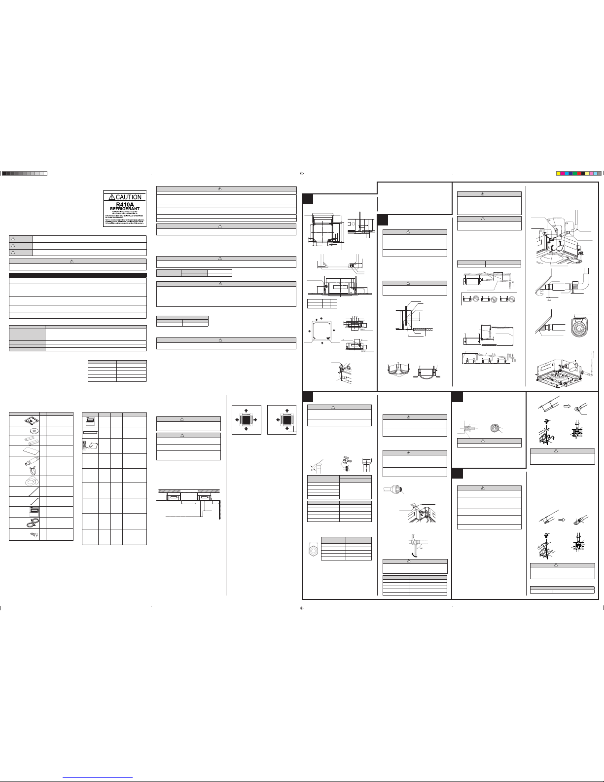
Cassette Type
1
STANDARD PARTS
The following installation parts are furnished.
Use them as required.
ACCESSORIES
Discharge Direction Setting
• The discharge direction can be selected as shown below.
SELECTING THE MOUNTING
POSITION
Especially, the installation place is very important for the split type air
conditioner because it is very diffi cult to move from place to place after
the fi rst installation.
Decide the mounting position together with the customer as follows:
WARNING
Select installation locations that can properly support
the weight of the indoor. Install the units securely so that
they do not topple or fall.
CAUTION
1 Do not install where there is the danger of combus-
tible gas leakage.
2 Do not install the unit near heat source of heat, steam,
or fl ammable gas.
3 If children under 10 years old may approach the unit,
take preventive measures so that they cannot reach
the unit.
(1) Install the indoor unit on a place having a suffi cient strength so that it
withstands against the weight of the indoor unit.
(2) The inlet and outlet ports should not be obstructed; the air should be
able to blow all over the room.
(3) Leave the space required to service the air conditioner.
(4) The ceiling rear height as shown in the fi gure.
(5) A place from where the air can be distributed evenly throughout the
room by the unit.
(6) A place from where drainage can be extracted outdoors easily.
(7) Install the unit where noise and vibrations are not amplifi ed.
INSTALLATION PROCEDURE
Install the air conditioner as follows:
* Select the most appropriate airfl ow direction from 3 or 4 directions ac-
cording to the shape of the room and the installation position.
* When changing the number of outlets, we recommend using the optional
AIR OUTLET SHUTTER PLATE KIT to close the outlet.
* For the specifi c closing pattern, please refer to the attached AIR OUTLET
SHUTTER PLATE KIT'S MANUAL. (Do so before installing the decorative panel as it will be installed on the body.)
* Be sure to make the function settings with the remote controller
according to the number of airfl ow outlets and the installed ceiling
height. (See 8 FUNCTION SETTING.)
(Continued to the next page)
(*1) This part is not furnished for AUT* series
OPTIONAL PARTS
PREPARATION BEFORE INSTALLATION
2
3. INSTALLING DRAIN PIPE
INDOOR UNIT INSTALLATION
(1) Positions of the ceiling opening, hanging bolt pitch, piping and ducts.
(unit: mm)
• Ceiling opening and hanging bolt pitch.
• Refrigerant piping and drain piping positions.
• Airfl ow split-fl ow duct and fresh air inlet positions.
Note)
Conduct proper insulation when connecting the split-fl ow ducts and
fresh air inlet.
(2) Setting the positions of hanging bolt and ceiling opening.
• Use an installation template (packaging top surface) to set the
positions of the hanging bolt and ceiling opening and drill holes.
(3) Hanging structure.
• Select a strong structure for the hanging location.
• If necessary, reinforce the hanging bolt with quakeproof columnar
support material to prevent shaking.
• Use hanging bolts of M8-M10.
1. BODY INSTALLATION
1)
Install the attached washer and nut (prepared on site) onto the hanging bolt.
2) Hook the body onto the hanging bolt.
3) Adjust the dimensions of the ceiling surface from the body.
After installing the decorative panel, you can make fi ne adjustment
of the height of the body. For details, refer to the installation manual
of the decorative panel.
2. LEVELING
Using a level, or vinyl hose fi lled with water, fi ne adjust so that the body
is level.
Inclined installation so as the drain pipe side is higher may cause a malfunction of the fl oat switch, and may cause water leakage.
This product can be installed at a height of up to 4.2 m (30Type : 3.6 m).
However, if the heights of the ceiling is higher than 3.2 m or lower than 2.7 m,
it is necessary to set the position from remote controller.
(See 8 FUNCTION SETTING.)
Model No.
UTB
- *
UD
UTR - YDZC
UTY - LRH*A1
Exterior
Summary
Unit control is performed by wired
remote controller
Install the plate at outlet
when carrying out 3-way
direction operation.
Unit control is performed by wireless
remote controller.
Parts name
Wired
remote
controller
Air outlet
shutter
plate
Wireless
remote
controller
and I, R,
receiver
unit
5 - 10 mm
VP25
35 mm
20 mm
Note)
Check for drainage
Pour about 1 liter of water from the position shown in the diagram or from
the airfl ow outlet to the dew tray. Check for any abnormalities such as
strange noises and whether the drain pump functions normally.
Working procedure
1) Install the attached drain hose to the drain port of the body. Install the
hose band from the top of the hose within the graphic display area.
2) Use vinyl adhesive agent to glue the drain piping (PVC pipe VP25)
which is prepared on site or elbow socket.
(Apply color adhesive agent evenly until the gauge line and seal)
3) Check the drainage. (See separate diagram)
4) Install the heat insulation.
5) Use the attached heat insulation to insulate the drain port and band
parts of the body.
B. For strand wiring
(1) Use ring terminals with insulating sleeves as shown in the fi gure
below to connect to the terminal block.
(2) Secur ely clamp the ring t erminals to the wir es using a n
appropriate tool so that the wires do not come loose.
(3) Use the specifi ed wires, connect them securely, and fasten them
so that there is no stress placed on the terminals.
(4) Use an appropriate screwdriver to tighten the terminal screws.
Do not use a screwdriver that is too small, otherwise, the screw
heads may be damaged and prevent the screws from being
properly tightened.
(5) Do not tighten the terminal screws too much, otherwise, the screws
may break.
(6) See the table 1 for the terminal screw tightening torques.
Strip 10 mm (13/32")
Sleeve
Screw with special washer
Screw with special washer
Ring terminal
Wire
Wire
Terminal
board
Terminal block
Ring terminal
Ring
terminal
Table 1
Strip 25 mm (31/32")
Loop
Screw with special washer
Screw with spe-
cial washer
Wire end
(Loop)
Wire end
(Loop)
Wire
Wire
Terminal
board
Terminal block
ELECTRICAL WIRING
5
4
INSTALLING THE COUPLER
HEAT INSULATION
Body
Be sure to overlap the
insulation
Coupler heat insulation
No gap
Coupler heat insulation
After checking for gas leaks, insulate by wrapping insulation around the
two parts (gas and liquid) of the indoor unit coupling, using the coupler
heat insulation.
After installing the coupler heat insulation, wrap both ends with vinyl tape
so that there is no gap.
A. For solid core wiring
(1) To connect the electrical terminal, follow the below diagram and
connect after looping it around the end of the wire.
(2) Use the specifi ed wires, connect them securely, and fasten them
so that there is no stress placed on the terminals.
(3) Use an appropriate screwdriver to tighten the terminal screws.
Do not use a screwdriver that is too small, otherwise, the screw
heads may be damaged and prevent the screws from being
properly tightened.
(4) Do not tighten the terminal screws too much, otherwise, the screws
may break.
(5) See the table 1 for the terminal screw tightening torques.
The pipes are shaped by your hands. Be careful not to collapse them.
Do not bend the pipes in an angle more than 90
°.
When pipes are repeatedly bend or stretched, the material will harden,
making it diffi cult to bend or stretch them any more. Do not bend or
stretch the pipes more than three times.
CAUTION
1 To prevent breaking of the pipe, avoid sharp bends.
Bend the pipe with a radius of curvature of 150 mm
or over.
2 If the pipe is bent repeatedly at the same place, it will
break.
2. BENDING PIPES
To prevent gas leakage, coat the fl are
surface with alkylbenzene oil (HAB).
Do not use mineral oil.
(3) When the fl are nut is tightened properly by your hand, use a torque
wrench to fi nally tighten it.
Torque wrench
Holding spanner
Body side
CAUTION
Hold the torque wrench at its grip, keeping it in the
right angle with the pipe, in order to tighten the fl are nut
correctly.
(2) Centering the pipe against port on the indoor unit, turn the fl are nut
with your hand.
Flare nut Tightening torque
6.35 mm (1/4 in.) dia.
9.52 mm (3/8 in.) dia.
12.70 mm (1/2 in.) dia.
15.88 mm (5/8 in.) dia.
19.05 mm (3/4 in.) dia.
3. CONNECTION PIPES
Indoor unit
(1) Detach the caps and plugs from the pipes.
CAUTION
1 Be sure to apply the pipe against the port on the in-
door unit correctly. If the centering is improper, the
fl are nut cannot be tightened smoothly. If the fl are
nut is forced to turn, the threads will be damaged.
2
Do not remove the fl are nut from the indoor unit pipe
until immediately before connecting the connection
pipe.
14 to 18 N·m (140 to 180 kgf·cm)
33 to 42 N·m (330 to 420 kgf·cm)
50 to 62 N·m (500 to 620 kgf·cm)
63 to 77 N·m (630 to 770 kgf·cm)
100 to 110 N·m (1,000 to 1,100 kgf·cm)
Connection pipe
(Liquid)
Connection pipe
(Gas)
CONNECTING THE PIPE
1. FLARING
(1) Cut the connection pipe to the necessary length with a pipe cutter.
(2) Hold the pipe downward so that cuttings will not enter the pipe and
remove the burrs.
(3) Insert the fl are nut (always use the fl are nut attached to the indoor
and outdoor units respectively) onto the pipe and perform the fl are
processing with a fl are tool.
Use the special R410A fl are tool, or the conventional fl are tool.
Check if [L] is fl ared uniformly and
is not cracked or scratched.
B
Die
A
Pipe
Width across
fl ats
6.35 mm (1/4 in.)
9.52 mm (3/8 in.)
12.70 mm (1/2 in.)
15.88 mm (5/8 in.)
19.05 mm (3/4 in.)
0 to 0.5
Pipe outside diameter
Dimension A
(mm)
Flare tool for R410A, clutch type
6.35 mm (1/4 in.)
9.52 mm (3/8 in.)
12.70 mm (1/2 in.)
15.88 mm (5/8 in.)
19.05 mm (3/4 in.)
9.1
13.2
16.6
19.7
24.0
Pipe outside diameter
Dimension B
(mm)
0
-0.4
When using conventional fl are tools to fl are R410A pipes, the dimension
A should be approximately 0.5 mm more than indicated in the table (for
fl aring with R410A fl are tools) to achieve the specifi ed fl aring. Use a
thickness gauge to measure the dimension A.
Pipe outside
diameter
Width across fl ats
of Flare nut
17 mm
22 mm
26 mm
29 mm
36 mm
6.35 mm (1/4 in.)
9.52 mm (3/8 in.)
12.70 mm (1/2 in.)
15.88 mm (5/8 in.)
19.05 mm (3/4 in.)
3
When sucking in the fresh air, please detach the insulation affi xed
to the drain pan.
Q’ty
1
8
2
1
1
1
1
3
1
1
1
2
Name and Shape
Template
(Carton top)
Washer
Coupler Heat
Insulation
Insulation
Drain Hose Assy
Hose Band Assy
Drain Pipe
Insulation
Binder (Large)
Binder (Small)
Wired Remote
Controller
Remote Controller
Cable(*1)
Tapping screw
(ø4 16)
Application
For installing indoor unit
For installing indoor unit
For indoor side pipe joint
For installing drain pipe
For installing drain pipe
For installing drain pipe
For installing drain pipe
For electrical wiring
For electrical wiring
For connecting the
remote controller
For installing the remote
controller
Copper pipes
It is necessary to use seamless copper pipes and it is desirable that the
amount of residual oil is less than 40 mg/10 m. Do not use copper pipes
having a collapsed, deformed or discolored portion (especially on the interior
surface). Otherwise, the expansion valve or capillary tube may become
blocked with contaminants.
As an air conditioner using R410A incurs pressure higher than when
using conventional refrigerant, it is necessary to choose adequate materials.
Thicknesses of copper pipes used with R410A are as shown in the table.
Never use copper pipes thinner than that in the table even when it is
available on the market.
Thicknesses of Annealed Copper Pipes (R410A)
Pipe outside diameter Thickness
6.35 mm (1/4 in.) 0.80 mm
9.52 mm (3/8 in.) 0.80 mm
12.70 mm (1/2 in.) 0.80 mm
15.88 mm (5/8 in.) 1.00 mm
19.05 mm (3/4 in.) 1.20 mm
For authorized service personnel only.
WARNING
1 For the air conditioner to operate satisfactorily, install it as outlined in this installation instruction sheet.
2 Connect the indoor unit and outdoor unit with the air conditioner piping and cables available from our standards parts. This
installation instruction sheet describes the correct connections using the installation set available from our standard
parts.
3 Installation work must be performed in accordance with national wiring standards by authorized personnel only.
4 If refrigerant leaks while work is being carried out, ventilate the area. If the refrigerant comes in contact with a fl ame, it
produces a toxic gas.
5 Do not use an extension cable.
6 Do not turn on the power until all installation work is complete.
CAUTION
This installation instruction sheet describes how to the indoor unit only.
To install the outdoor unit, refer to the installation instruction sheet included with the outdoor unit.
Be careful not to scratch the air conditioner when handling it.
After installation, explain correct operation to the customer, using the operating manual.
Let the customer keep this installation instruction sheet because it is used when the air conditioner is serviced or moved.
CONNECTION PIPE REQUIREMENT
CAUTION
Refer to the installation instruction sheet of the outdoor unit for description of the length of connecting pipe or for difference
of its elevation.
Diameter
Liquid 9.52 mm (3/8 in.)
Gas 15.88 mm (5/8 in.)
Use pipe with water-resistant heat insulation.
CAUTION
Install heat insulation around both the gas and liquid pipes. Failure to do so may cause water leaks.
Use heat insulation with heat resistance above 120 °C. (Reverse cycle model only)
In addition, if the humidity level at the installation location of the refrigerant piping is expected to exceed 70%, install heat
insulation around the refrigerant piping. If the expected humidity level is 70-80%, use heat insulation that is 15 mm or thicker
and if the expected humidity exceeds 80%, use heat insulation that is 20 mm or thicker.
If heat insulation is used that is not as thick as specifi ed, condensation may form on the surface of the insulation.
In addition, use heat insulation with heat conductivity of 0.045 W/(m·K) or less (at 20 °C).
ELECTRICAL REQUIREMENT
Connection cable (mm2)
MAX. MIN.
2.5 1.5
Use conformed cable with Type 245 IEC57.
Install all electrical works in accordance to the standard.
Install the disconnect device with a contact gap of at least 3 mm in all poles nearby the units. (Both indoor unit and outdoor unit)
CAUTION
Be sure to execute the electrical work according to the Lows of each country and the Installation Instructions.
In addition, be sure to set as exclusive line and use the rated voltage and circuit breaker.
Floor
Obstruction
1,500 mm
or more
1,800 mm or more
1,000 mm
or more
3,000 mm or more
Strong and durable ceiling
4 DIRECTION
100 mm
or more*
3 DIRECTION
*Please ensure suffi cient maintenance space during installation.
A
B
20 - 45 mm
20 - 45 mm
50 mm
200 mm
130 mm
130 mm
699 mm (Hanging bolt pitch)
950 mm (Panel frame)
860 - 910 mm (Ceiling opening)
840 mm (Body frame)
795 mm (Hanging bolt pitch)
20 - 45 mm
50 - 100 mm
140 - 145 mm
10 mm
40 mm
20 - 45 mm
80 mm
130 mm
840 mm (Body frame)
860 - 910 mm (Ceiling opening)
950 mm (Panel frame)
10 mm
80 mm
60 mm278 mm358 mm
140 mm
180 mm
200 mm
Gas pipe
Liquid pipe
Drain pipe
(Connect the attached
drain hose)
Model A B
24LB 246 256
30/36/45/54LB 288 298
88 mm
70 mm
250 mm
352 mm
100 mm
83 mm83 mm
90 mm
100 mm
185 mm
185 mm
Airfl ow split-fl ow duct connecting port
Airfl ow split-fl ow duct connecting port
Refrigerant
pipe
Cut out
Cut out
Detailed diagram of branched duct connecting port
(4 sides)
Fresh air inlet position
2.5 mm hole
2.5 mm hole
Burling hole pitch
Fresh air inlet position
Drain pipe
Airfl ow split-fl ow duct
connecting port
Airfl ow split-fl ow duct
connecting port
Insulation
Fresh air inlet position
CAUTION
1 Do not use mineral oil on fl ared part. Prevent mineral
oil from getting into the system as this would reduce
the lifetime of the units.
2 While welding the pipes, be sure to blow dry nitrogen
gas through them.
WARNING
1 Install the air conditioner in a location which can
withstand a load do at least fi ve times the weight
of the main unit and which will not amplify sound
or vibration. If the installation location is not strong
enough, the indoor unit may fall and cause injuries.
2 If the job is done with the panel frame only, there is a
risk that the unit will come loose. Please take care.
WARNING
•
Perform fi nal tightening by tightening the double nut fi rmly.
•
Be sure to install the body horizontally and adjust the
height below the body and the ceiling surface properly.
10~15
After installing the body,
tighten the nuts.
Hanging bolt
Nut A
Washer
Washer
Nut B (Double Nut)
30 or more
CAUTION
Must fi t tightly against body without any gap.
WARNING
1 Before starting work, check that power is not being
supplied to the indoor unit and outdoor unit.
2 Match the terminal board numbers and connection
cable colors with those of the outdoor unit.
Erroneous wiring may cause burning of the electric
parts.
3 Connect the connection cables fi rmly to the terminal
board. Imperfect installation may cause a fi re.
4 Always fasten the outside covering of the connection
cable with the cable clamp. (If the insulator is chafed,
electric leakage may occur.)
5 Always connect the ground wire.
Install the knob
faces upward
Attached drain hose
heat insulation
Attached
hose band
Locally arranged
vinyl pipe
Attached drain hose
Attached heat insulation
Applying area
of adhesive
Hose band
Gauge line
Make sure there are no gaps
4 mm or less
Wind the attached heat insulation
around the hose band
Make sure the alignment
is on top
(a) Top view
(c) Top view
(d) Hose opening view
(b) Side view
WARNING
When using solid core wires, do not use the attached
ring terminal. If you use the solid core wires with the ring
terminal, the ring terminal’s pressure bonding may malfunction and cause the wires to abnormally heat up.
WARNING
Use ring terminals and tighten the terminal screws to
the specifi ed torques, otherwise, abnormal overheating
may be produced and possibly cause heavy damage
inside the unit.
Tightening torque
M4 screw 12 to 18 N·m (12 to 18 kgf·cm)
Vinyl hoses
Drain pipe
WARNING
•
Do not insert the drain piping into the sewer where sulfurous gas occurs. (Heat exchange erosion may occur)
•
Insulate the parts properly so that water will not drip
from the connection parts.
•
Check for proper drainage after the construction by
using the visible portion of transparent drain port and
the drain piping fi nal outlet on the body.
CAUTION
• Do not apply adhesive agent on the drain port of the
body. (Use the attached drain hose and connect the
drain piping)
Note: Install the drain pipe.
Install the drain pipe with downward gradient (1/50 to 1/100) and so
there are no rises or traps in the pipe.
Use general hard polyvinyl chloride pipe (VP25) [outside diameter
32 mm] and connect it with adhesive (polyvinyl chloride) so that there
is no leakage.
When the pipe is long, install supporters.
Do not perform air bleeding.
Always heat insulate the indoor side of the drain pipe.
If it is impossible to have suffi cient gradient of pipe, perform drain
lift-up.
Pipe size
Drain pipe VP25 (O.D. 32 mm)
Hanging fi ttings
1.5 to 2 m
VP25 (O.D. 32 mm)
Downward gradient 1/100 to 1/50
Rise
PROHIBITED:
Trap
Air bleeding
When lifting up drain:
• Height of inclined pipe should be less than 850 mm from the ceiling.
A rise dimension over this range will cause leakage.
• Lift up the pipe vertically at the position of 300 mm or less from the
unit.
300 mm or less
VP25 (O.D. 32 mm)
local arrangement
850 mm or less
Horizontal or upward gradient
Downward gradient
1/100 to 1/50
VP30 (O.D. 38 mm) or more
Downward gradient 1/100 to 1/50
850 mm or less
9378590014-07_IM_EN.indd 19378590014-07_IM_EN.indd 1 8/30/2012 9:45:21 AM8/30/2012 9:45:21 AM
Page 2
CUSTOMER GUIDANCE
Explain the following to the customer in accordance with the operating
manual:
(1) Starting and stopping method, operation switching, temperature
adjustment, timer, air fl ow switching, and other remote controller
operations.
(2) Air fi lter removal and cleaning, and how to use the air louvers.
(3) Give the operating and installation manuals to the customer.
(4) If the signal code is changed, explain to the customer how it changed
(the system returns to signal code A when the batteries in the remote
controller are replaced).
*(4) is applicable to using wireless remote controller.
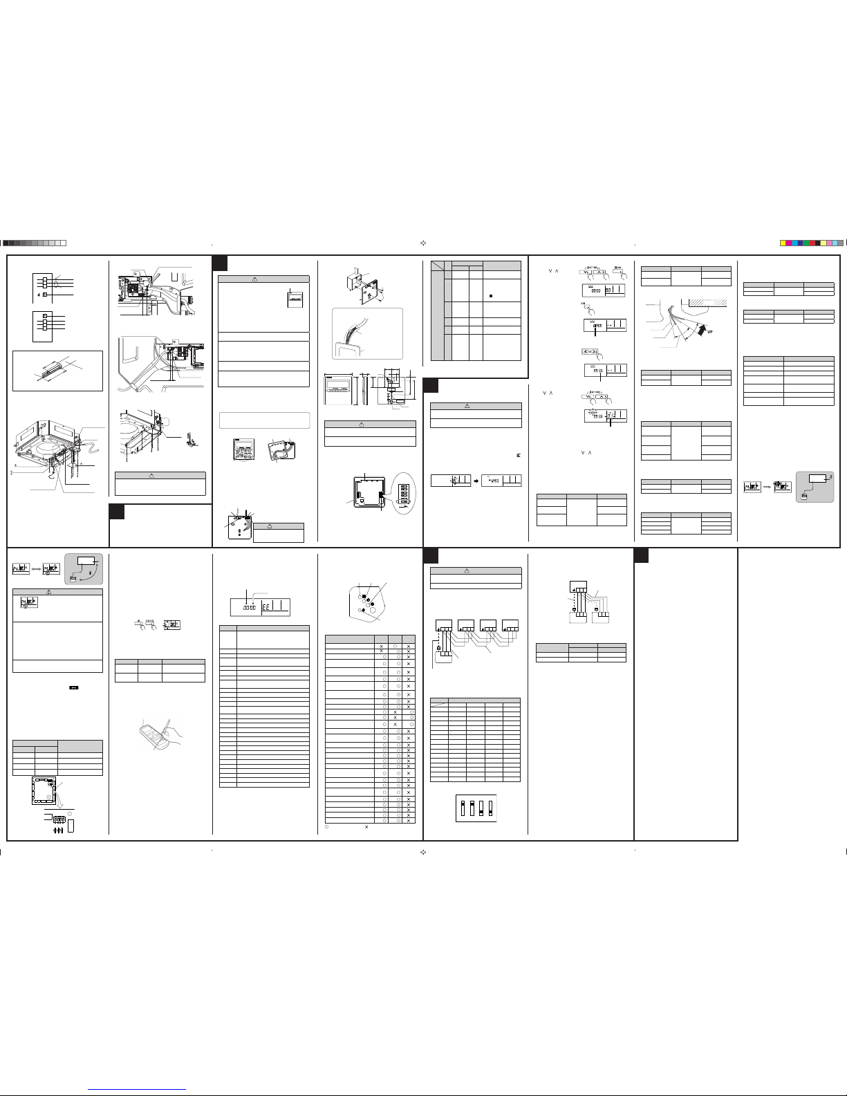
REMOTE CONTROLLER
SETTING
7
10
(4) Press the SET TEMP. buttons
(
) ( ) to select the setting
value.
The display fl ashes as shown
to the right during setting value
selection.
(5) Press the TIMER SET button
to confi rm the setting.
Press the TIMER SET button
for a few seconds until the
setting value stops fl ashing.
If the setting value display changes or if “- -” is
displayed when the fl ashing stops, the setting value has not been set
correctly.
(An invalid setting value may have been selected for the indoor unit.)
(6) Repeat steps 2 to 5 to perform additional settings.
Press the SET TEMP. buttons (
) ( ) and FAN button simultaneously again for more than 5 seconds to cancel the function setting
mode. In addition, the function setting mode will be automatically
canceled after 1 minute if no operation is performed.
(7) After completing the FUNCTION SETTING, be sure to turn off the
power and turn it on again.
2. FUNCTION SETTING
This procedure changes to the function settings used to control the
indoor unit according to the installation conditions. Incorrect settings
can cause the indoor unit malfunction.
After the power is turned on, perform the “FUNCTION SETTING”
according to the installation conditions using the remote controller.
The settings may be selected between the following two: Function
Number or Setting Value.
Settings will not be changed if invalid numbers or setting values are
selected.
Operation Method
(1) Press the SET TEMP. but-
tons (
) ( ) and FAN button simultaneously for more
than 5 seconds to enter the
function setting mode.
(2) Press the SET BACK button
to select the indoor unit number.
(3) Press the SET TIME ( < > )
buttons to select the function
number.
Unit number of INDOOR UNIT
Standard
Ceiling
Upward
Swing range
Function number
SUMOTUWETH FR
SA
SET BACK
SUMOTUWETH FR
SA
SUMOTUWETH FR
SA
Setting value
SUMOTUWETH FR
SA
PART No. 9378590014-07
NO.
SW state
Detail
OFF ON
DIP
switch 1
1
★
Cannot be used. (Do not
change)
2
★
Dual remote controller
setting
*
Refer to 2. DUAL REMOTE CONTROLLERS
in 9 SPECIAL INSTALLATION METHODS.
3
Follow the
selection in
FUNCTION
SETTING
Invalidity
Filter reset operation and
fi lter display
4
★
Cannot be used. (Do not
change)
5
★
Cannot be used. (Do not
change)
6
★ Invalidity
Validity
Memory backup setting
* Set to ON to use batteries
for the memory backup. If
batteries are not used, all
of the settings stored in
memory will be deleted if
there is a power failure.
(★ Factory setting)
CASSETTE GRILLE
INSTALLATION
• Operate according to the Installation instruction sheet CASSETTE
GRILLE.
• Be sure to confi rm there is no gap between the panel and main unit after
installing the CASSETTE GRILLE.
8
FUNCTION SETTING
AND TEST RUN
1. TURNING ON THE POWER
1. Check the remote controller wiring and DIP switch settings.
2. Install the front case.
*
When installing the front case, connect the connector to the front case.
3. Check the indoor and outdoor unit wiring and circuit board switch
settings, and then turn on the indoor and outdoor units. After “
”
has fl ashed on the set temperature display for several seconds, the
clock display will appear in the center of the remote controller display.
The clock display will appear in the center of the remote controller
display.
SUMOTUWETH FR
SA
Setting the Ceiling Height
Select the setting values in the table below according to the height of
the ceiling. (The unit is factory-set to “00”.)
The ceiling height values are for the 4-way outlet.
Do not change this setting in the 3-way or 2-way outlet mode.
SPECIAL INSTALLATION
METHODS
2. DUAL REMOTE CONTROLLERS
• Two separate remote controllers can be used to operate the indoor
units.
•
The timer and self-diagnosis functions cannot be used on the secondary
units.
3 4
ON
1 2
Example : No. 3
1. GROUP CONTROL SYSTEM
A number of indoor units can be operated at the same time using a
single remote controller.
(1) Wiring method (indoor unit to remote controller)
(2) DIP switch setting (indoor unit)
Set the unit number of each indoor unit using DIP switch on the indoor
unit circuit board. (see following table and fi gure.)
DIP switch is normally set to make unit number No. 0.
Remote controller
Bus wire
Remote controller cable
Indoor unit 2Indoor unit 1Indoor unit 0 Indoor unit 3
When ground wire is necessary
123
123
123 123 123
0
1
2
3
4
5
6
7
8
9
10
11
12
13
14
15
1
OFF
ON
OFF
ON
OFF
ON
OFF
ON
OFF
ON
OFF
ON
OFF
ON
OFF
ON
2
OFF
OFF
ON
ON
OFF
OFF
ON
ON
OFF
OFF
ON
ON
OFF
OFF
ON
ON
3
OFF
OFF
OFF
OFF
ON
ON
ON
ON
OFF
OFF
OFF
OFF
ON
ON
ON
ON
4
OFF
OFF
OFF
OFF
OFF
OFF
OFF
OFF
ON
ON
ON
ON
ON
ON
ON
ON
Unit number DIP SWITCH No.
Indoor unit
(1) Wiring method (indoor unit to remote controller)
Remote controller cable
Indoor unit
When ground wire
is necessary
Remote controller
Secondary unit
Primary unit
Number of remote
controllers
Primary unit Secondary unit
DIP SW 1 No. 2
OFF
OFF
DIP SW 1 No. 2
–
ON
1 (Normal)
2 (Dual)
(2) Remote controller DIP switch 1 setting
Set the remote controller DIP switch 1 No. 2 according to the following
table.
1 231 23
1 2 3
9
B
Indoor unit
Setting Other Functions
The following settings are also possible, depending on the operating
conditions. (The unit is factory-set to “00”.)
Auto Restart
Indoor Room Temperature Sensor Switching Function (Wired remote
controller only)
If setting value is “00”, room temperature is controlled by the indoor unit
temperature sensor.
If setting value is “01”, room temperature is controlled by either indoor
unit temperature sensor or remote controller sensor.
After completing the FUNCTION SETTING, be sure to turn off the power
and turn it on again.
Setting record
Record any changes to the settings in the following table.
A
SETTING THE ROOM TEMPERATURE
DETECTION LOCATION
The detection location of the room temperature can be selected from the
following two examples. Choose the detection location that is best for the
installation location.
A. Indoor unit setting (factory setting)
The room temperature is detected by the indoor unit temperature sensor.
(1) When the THERMO SENSOR button is pressed, the lock display
fl ashes because the function is locked at the factory.
Indoor unit
B. Indoor unit/remote controller setting (room
temperature sensor selection)
The temperature sensor of the indoor unit or the remote controller can be
used to detect the room temperature.
(1) Enable the room temperature sensor selection in FUNCTION SET-
TING, which will be described later.
(2) Press the THERMO SENSOR button for 5 seconds or more to select
the temperature sensor of the indoor unit or the remote controller.
• To prevent from draft, we recommend using "upward mode".
• In certain condition, the ceiling may become dirty. In such case, we re commend using the optional "PANEL SPACER KIT".
Set the vertical direction adjusting scope.
Outlet cross section
Setting the Filter Sign
The indoor unit has a sign to inform the user that it is time to clean the
fi lter.
Select the time setting for the fi lter sign display interval in the table
below according to the amount of dust or debris in the room. (The unit
is factory-set to “00”.)
If you do not wish the fi lter sign to be displayed, select the setting value
for “No indication”.
Setting the Outlet Directions
Select the setting values in the table below for using a 3-way or 2-way
outlet. (The unit is factory-set to “00”.)
Setting the Cooler Room Temperature Correction
Depending on the installed environment, the room temperature sensor
may require a correction. The settings may be selected as shown in the
table below. (The unit is factory-set to “00”.)
Setting the Heater Room Temperature Correction
Depending on the installed environment, the room temperature sensor
may require a correction. The settings may be changed as shown in
the table below. (The unit is factory-set to “00”.)
[Example]
Remote
controller cable
Box
Screws
Connector
Rear case
Unit: mm
8
6
30
23
120
120
17
45.3
4.5
4.5
Hole × 2
Hole × 3
4.5
12.5
63.5
15.3
83.5
Hole
33.5
2. SETTING THE DIP SWITCHES
Set the remote controller DIP switches.
[Example]
ONONOFF
1
2
3
4
5
6
DIP switch 1
Front case (back side)
Do not use this
DIP switch 2
Wrap the connector and remote
controller wires with vinyl tape or
some other type of insulation as
shown in the fi gure.
Ground the remote controller if it has a
ground wire.
Remote controller
When remote controller cable is embedded
(1) Embed the remote controller cable and box.
(2) Pass the remote controller cable through the hole in the rear case and
connect the remote controller cable to the remote controller terminal
board specifi ed in fi gure.
(3) Clamp the remote controller cable sheath with the binder as shown in
fi gure.
(4) Cut off the excess binder.
(5) Install the rear case to the wall, box, etc., with two screws fi gure.
Screws
SET BACK
Front case
(back side)
Rear case
Connector
1. INSTALLING THE REMOTE CONTROLLER
Open the operation panel on the front of the remote controller, remove
the two screws indicated in the following fi gure, and then remove the front
case of the remote controller.
When installing the remote controller, remove the connector from the
front case. The wires may break if the connector is not removed and
the front case hangs down.
When installing the front case, connect the connector to the front case.
(2) Please fi x the Connection Cable with Cable Clamp. And then install
the Wire Cover with screws.
(3) Install control box cover.
Detail (a)
Detail (b)
Detail (c)
6
1. CONNECTION DIAGRAMS
*
Ground the remote controller if it has a ground wire
Connection cable (to outdoor unit)
Wired remote controller cable
3
2
1
Black
White
Red
*
Indoor unit
side
3
2
1
Power line
Control line
Indoor unit
side
Power supply
cable or connection cable
( a )
( b )
Control box cover
Wiring connecting port
Connection
cable clamp
Wiring cover
Power terminal board
Remote control terminal board
Remote Controller connecting port
Cure the wiring connecting port and
remote controller connecting port with
paste or heat insulation so that insects
or dust will not enter the unit
Fuse
250V 3.15A
20 mm
30 mm or more
Earth wire
• Use a 4-core wire cable.
Keep the earth wire longer than the other wires.
(1) Remove the control box cover and install each connection wire.
Please fi rmly tighten Connection cables and Remote Controller
cables with the attached binder.
2. CONNECTION OF WIRING
TROUBLESHOOTING (Option)
[Troubleshooting with the indoor display]
Troubleshooting at the display is possible either on the wired or wireless
remote controller.
The OPERATION, TIMER and FILTER lamp operate as follows table according to the error contents.
FILTER LAMP
(RED)
TIMER LAMP
(ORANGE)
OPERATION LAMP
(GREEN)
MANUAL AUTO
[Troubleshooting at the remote controller LCD]
This is possible only on the wired remote controller.
[SELF-DIAGNOSIS]
If an error occurs, the following display will be shown.
(“EE” will appear in the set room temperature display.)
Unit number
Error code
Ex. Self-diagnosis
SUMOTUWETH FR
SA
If “CO” appears in the unit number display, there is a remote controller
error. Refer to the installation instruction sheet included with the remote
controller.
Error code
1d
1C
Content
Incompatible indoor unit is
connected
Indoor unit remote controller
communication error
Unit number
C0
C0
Transmitter section
Test run button
[Using the wireless remote controller] (Option)
• For the operation method, refer to the operating manual.
• The outdoor unit may not operate depending on the room temperature.
In this case, press the test run button on the remote controller while
the air conditioner is running. (Point the transmitter section of the
remote controller toward the air conditioner and press the test run button
with the tip of a ball-point pen, etc.)
•
To end test operation, press the remote controller START/STOP button.
(When the air conditioner is run by pressing the test run button, the
OPERATION indicator lamp and TIMER indicator lamp will simultaneously fl ash slowly.)
3. TEST RUN
CHECK ITEMS
(1) Is operation of each button on the remote controller normal?
(2) Does each lamp light normally?
(3) Do not air fl ow direction louvers operate normally?
(4) Is the drain normal?
(5) Is there any abnormal noise and vibration during operation?
• Do not operate the air conditioner in the running state for a long time.
[OPERATION METHOD]
• For the operation method, refer to the operating manual.
(1) Stop the air conditioner operation.
(2) Press the MODE button and the FAN button simultaneously for
2 seconds or more to start the test run.
(3) Press the START/STOP button to stop the test run.
Test run display
NOTES
If the function to change the temperature sensor is used as shown in
examples A (other than example B), be sure to lock the detection location. If the function is locked, the lock display
will fl ash when the
THERMO SENSOR button is pressed.
Jumper wire
JM2
Connect
Connect
Disconnect
Disconnect
Remote controller
signal code
A (Primary setting)
B
C
D
JM1
Connect
Disconnect
Connect
Disconnect
[When using the wireless remote controller]
(Option)
SWITCHING REMOTE CONTROLLER SIGNAL
CODES
Confi rm the setting of the remote controller signal code and the printed
circuit board setting.
If these are not confi rmed, the remote controller cannot be used to
operate for the air conditioner.
Indoor unit
Printed circuit board
CAUTION
1 When select the “Remote controller set-
ting” , if the detected temperature value
between the temperature sensor of the
indoor unit and the temperature sensor
of the remote controller varies signifi cantly, it is
likely to return to the control status of temperature
sensor of the indoor unit temporarily.
2 As the temperature sensor of remote controller de-
tects the temperature near the wall, when there is a
certain difference between the room temperature and
the wall temperature, the sensor will not detect the
room temperature correctly sometimes.
Especially when the outer side of the wall on which the
sensor is positioned is exposed to the open air, it is recommended to use the temperature sensor of the indoor
unit to detect the room temperature when the indoor and
outdoor temperature difference is signifi cant.
3
The temperature sensor of the remote controller is not
only used when there is a problem in the detection of
the temperature sensor of the indoor unit.
CAUTION
1
When detecting the room temperature using the remote controller, please set up the
remote controller according to the following
conditions. If the remote controller is not well
set, the correct room temperature will not be
detected, and thus the abnormal conditions like
“not cooled” or “not heated” will occur even if
the air-conditioner is running normally
.
A location with an average temperature for the room being
airconditioned.
Not directly exposed to the outlet air from the air-conditioner.
Out of direct sunlight.
Away from the infl uence of other heat sources.
2 Do not touch the remote controller PC board and PC
board parts directly with your hands.
3
Do not wire the remote controller cable and the bus
wire together with or parallel to the connection cables,
transmission cables, and power supply cables of the
indoor and outdoor units. It may cause erroneous
operation
.
4 When installing the bus wire near a source of electro-
magnetic waves, use shielded wire.
5
Do not set the DIP switches, either on the air conditioner
or the remote controller, in any way other than indicated
in this sheet or the manual that is supplied with the air
conditioner. Doing so may result in an accident.
Temperature sensor
( c )
Bind securely
Cable clamp
Thread the binder through
the hole and tighten securely
Binder (Large)
Cut off the excess
10mm and above
Thread the binder through the
hole and tighten securely
5mm and above
Binder (Large)
Cut off the excess
CAUTION
Do not bundle the remote controller cable, or wire the
remote controller cable in parallel, with the indoor unit
connection wire (to the outdoor unit) and the power supply cable. It may cause erroneous operation.
Binder
(Small)
1. Red
2. White
3. Black
Hole
t
CAUTION
When connecting the
remote controller wires, do
not overtighten the screws.
Error code Error contents
01
13
26
27
Indoor signal error
00
Wired remote controller error
02
Indoor room temperature sensor error
04
Indoor heat exchanger temperature sensor (middle)
error
28
Indoor heat exchanger temperature sensor (inlet) error
09
Float switch operated
0C
Outdoor discharge pipe temperature sensor error
06
Outdoor heat exchanger temperature sensor (outlet)
error
0A
Outdoor temperature sensor error
15
Compressor temperature sensor error
1d
2-way valve temperature sensor error
1E
3-way valve temperature sensor error
29
Outdoor heat exchanger temperature sensor (middle)
error
20
Indoor manual auto switch error
2A
Power supply frequency detection error
17
IPM protection
18
CT error
1A
Compressor location error
1b
Outdoor fan error
1F
Connected indoor unit error
1C
Outdoor unit computer communication error
12
Indoor fan error
0F
Discharge temperature error
24
Excessive high pressure protection on cooling
2C
4-way valve error
16
Pressure switch error
2b
Compressor temperature error
19
Active fi lter error
25
PFC circuit error
CAUTION
1 Install the remote controller wires so as not to be
direct touched with your hand.
2 Do not touch the remote controller PC board and PC
board parts directly with your hands.
Error contents
OPERA-
TION
lamp
TIMER
lamp
FILTER
lamp
Indoor signal error
Wired remote controller error
(8 times)
Indoor room temperature sensor error
(2 times)
(2 times)
Indoor heat exchanger temperature
sensor (middle) error
(2 times)
(3 times)
Indoor heat exchanger temperature sensor (inlet) error
(2 times)
(4 times)
Float switch operated
(2 times)
(6 times)
Outdoor discharge pipe temperature
sensor error
(3 times)
(2 times)
Outdoor heat exchanger temperature
sensor (outlet) error
(3 times)
(3 times)
Outdoor temperature sensor error
(3 times)
(4 times)
Compressor temperature sensor error
(3 times)
(8 times)
2-way valve temperature sensor error
(3 times)
(2 times)
3-way valve temperature sensor error
(3 times)
(3 times)
Outdoor heat exchanger temperature
sensor (middle) error
(3 times)
(4 times)
Indoor manual auto switch error
(4 times)
(2 times)
Power supply frequency detection
error
(4 times)
(4 times)
IPM protection
(5 times)
(2 times)
CT error
(5 times)
(3 times)
Compressor location error
(5 times)
(5 times)
Outdoor fan error
(5 times)
(6 times)
Connected indoor unit error
(5 times)
(7 times)
Outdoor unit computer communication error
(5 times)
(8 times)
Indoor fan error
(6 times)
(2 or 3 times)
Discharge temperature error
(7 times)
(2 times)
Excessive high pressure protection
on cooling
(7 times)
(3 times)
4-way valve error
(7 times)
(4 times)
Pressure switch error
(7 times)
(5 times)
Compressor temperature error
(7 times)
(6 times)
Active fi lter error
(8 times)
(2 or 3 times)
PFC circuit error
(8 times)
(4 times)
: 0.5s ON/0.5s OFF (Flash) : OFF
CAUTION
1 Confi rm whether the wiring work for outdoor unit has
been fi nished.
2 Confi rm whether the cap for electric control box on
the outdoor unit is close.
CAUTION
1 When setting DIP switches, do not touch any other parts
on the circuit board directly with your bare hands.
2 Be sure to turn off the main power.
Setting Setting Value
Ceiling height
Outlet directions
Filter sign
Cooler room temperature
correction
Heater room temperature
correction
Auto restart
Indoor room temperature
sensor switching function
Setting Description [m]
Function Number Setting Value
Standard
3.2 m
20
00
Low ceiling
2.7 m
01
High ceiling
30 Type 3.6m
36,45,54 Type 4.2m
02
Setting Description Function Number Setting Value
Standard
31
00
Lower control 01
Slightly warmer control
02
Warmer control 03
Setting Description Function Number Setting Value
Standard
30
00
Lower control 01
Setting Description Function Number Setting Value
Standard
23
00
Upward 01
Setting Description Function Number Setting Value
4-way
22
00
3-way 01
Setting Description Function Number Setting Value
Standard
(2,500 hours)
11
00
Long interval
(4,400 hours)
01
Short interval
(1,250 hours)
02
No indication 03
Setting Description Function Number Setting Value
Yes
40
00
No 01
Setting Description Function Number Setting Value
Yes
42
00
No 01
9378590014-07_IM_EN.indd 29378590014-07_IM_EN.indd 2 8/30/2012 9:46:24 AM8/30/2012 9:46:24 AM
 Loading...