

Page 1

SPLIT TYPE ROOM
AIR CONDITIONER
WALL MOUNTED
type
Models
Indoor unit Outdoor unit
ASY9USCCW AOY9USCC
ASY9USCCW AOY9UFCC
ASY12USCCW AOY12USCC
CONTENTS
SPECIFICATIONS . . . . . . . . . . . . . . . . . .
OUTLINE AND DIMENSIONS . . . . . . . . .
REFRIGERANT SYSTEM DIAGRAM . . .
CIRCUIT DIAGRAM . . . . . . . . . . . . . . . . .
INDOOR PCB CIRCUIT DIAGRAM . . . . .
DISASSEMBLY ILLUSTRATION . . . . . . .
PARTS LIST . . . . . . . . . . . . . . . . . . . . . .
1
4
5
7
ERROR CONTENTS . . . . . . . . . . . . . . . . 8
14
STANDARD ACCESSORIES . . . . . . . . .16
9
2
Page 2
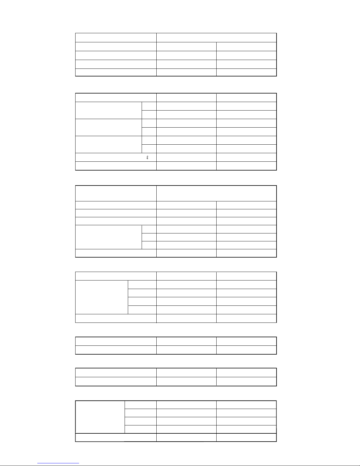
SPECIFICATIONS
TYPE COOLING & HEATING
INDOOR UNIT
OUTDOOR UNIT
COOLING CAPACITY
HEATING CAPACITY
COMPRESSOR
DIMENSIONS
TYPE
DISCRIMINATION
POWER SOURCE
REFRIGERANT
REFRIGERANT CHARGE
ADDITIONAL REFRIGERANT
R410A
Pipe length
7.5 m
10 m
15 m
Hermetic type, Permanet split condenser,
2 pole, Single phase, Induction motor, Rotary
HI-SPEED
INDOOR UNIT
POWER SUPPLY
MED-SPEED
LO-SPEED
QUIET
(r.p.m.)
OUTDOOR UNIT
(r.p.m.)
INDOOR UNIT H x W x D
H x W x D
OUTDOOR UNIT
FAN MOTOR
WEIGHT
INDOOR UNIT
GROSS / NET
HI-SPEED
MED-SPEED
LO-SPEED
SUPER QUIET
GROSS / NET
(dB)
OUTDOOR UNIT
INDOOR UNIT
NOISE LEVEL
POWER SOURCE
RUNNING CURRENT
(A)
COOL
HEAT
INPUT WATTS
(kW)
COOL
HEAT
E.E.R.
(kW/kW)
COOL
HEAT
MOISTURE REMOVAL
AIR CIRCULATION HIGH
ELECTRICAL DATA
(m /hr)
3
AOY12USCC
ASY12USCCW
3.95 kW
3.25 kW
230V 50Hz
5.9
5.6
1.35
1.28
2.41
3.09
1.8
COOL 535 HEAT 545
802-361-35B
750 g
COOL 40 HEAT 40
COOL 38 HEAT 38
COOL 36 HEAT 35
COOL 33 HEAT 32
COOL 1310 HEAT 1330
COOL 1200 HEAT 1210
COOL 1090 HEAT 1090
COOL 980 HEAT 980
770
230 V
257 x 808 x 187 mm
535 x 695 x 250 mm
10 kg / 8 kg
34 kg / 31 kg
COOL 48 HEAT 48
ASY9USCCW
AOY9USCC, AOY9UFCC
2.95 kW
2.60 kW
230V 50Hz
4.8
4.1
1.07
0.90
2.43
3.28
1.3
COOL 540 HEAT 515
802-141-45B
220, 230, 240V / 50Hz
220, 230, 240V / 50Hz
650 g
20 g/m20 g/m
900 g800 g
800 g700 g
750 g650 g
COOL 1310 HEAT 1250
COOL 1170 HEAT 1140
COOL 1030 HEAT 1020
800
COOL 40 HEAT 38
COOL 38 HEAT 36
COOL 35 HEAT 34
COOL 30 HEAT 28
COOL 900 HEAT 900
230 V
257 x 808 x 187 mm
535 x 650 x 250 mm
10 kg / 8 kg
29 kg / 26 kg
COOL 46 HEAT 46
OUTDOOR UNIT
(dB)
/h )(
1
2004.11.30
Page 3
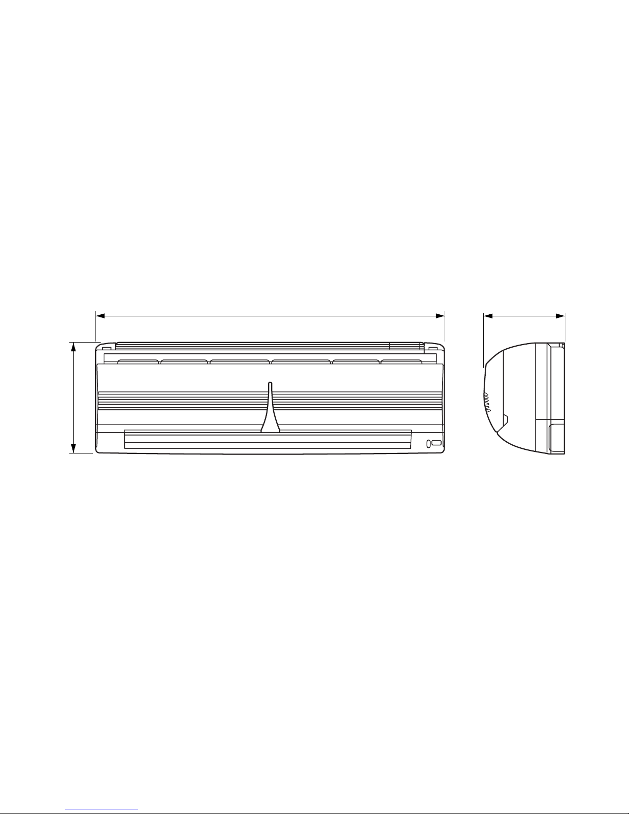
INDOOR UNIT
Unit : mm
DIMENSIONS
22004.11.30
187
808
257
Page 4

695 250
500
Drain pipe hold 20
440
290
265
54
535
13
98
Unit : mm
O
OUTDOOR UNIT
250
650
535
Model : AOY9USCC
AOY9UFCC
Model : AOY12USCC
32004.11.30
Page 5
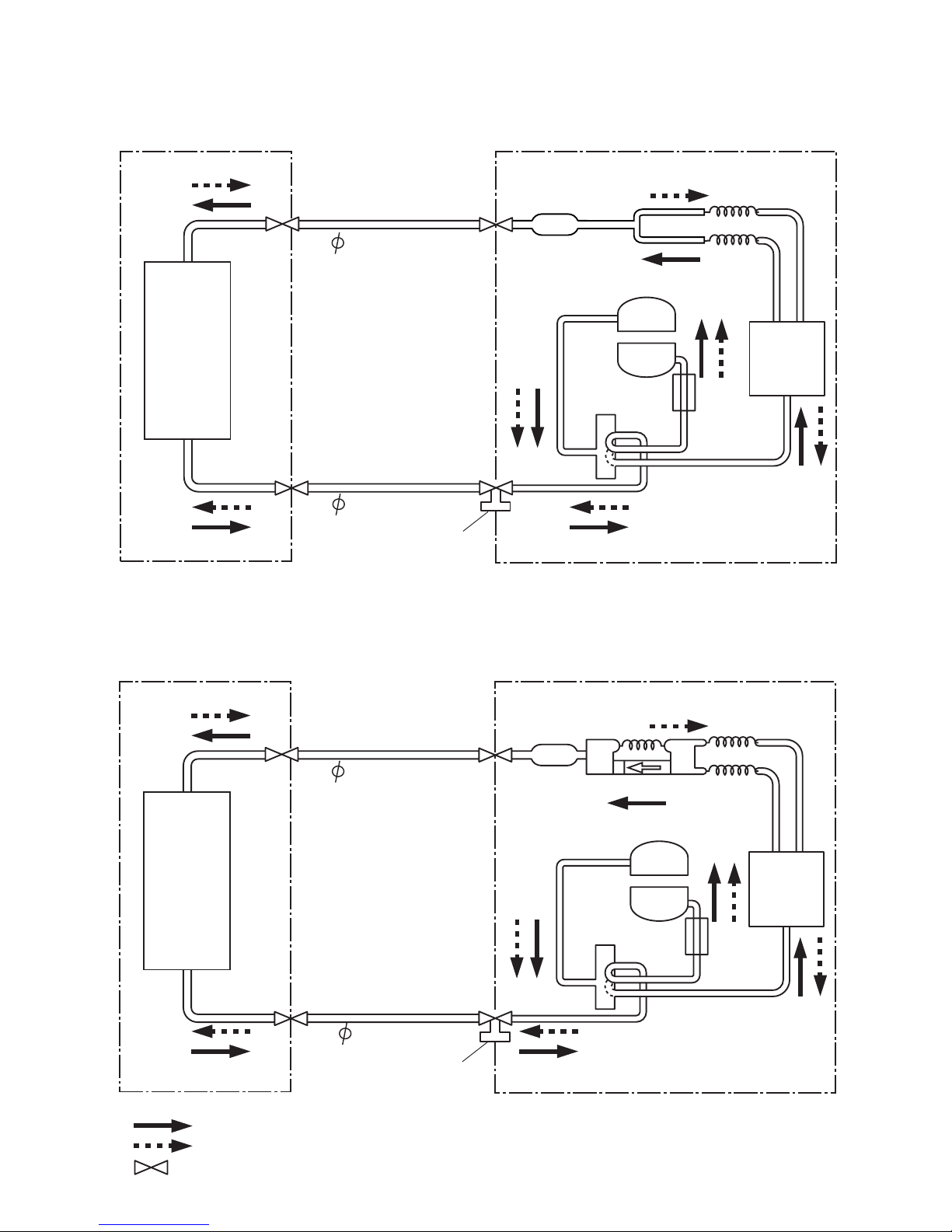
REFRIGERANT SYSTEM DIAGRAM
Models : ASY9USCCW / AOY9USCC
ASY9USCCW / AOY9UFCC
Models : ASY12USCCW / AOY12USCC
9.52mm(3/8")
Cooling
Heating
: Flare coupling
Compressor
Capillary tube
for heating
Capillary tube
for heating and cooling
OUTDOOR UNIT
INDOOR UNIT
Condenser
9.52mm(3/8")
Refrigerant pipe
Refrigerant pipe
6.35mm(1/4")
Charging valve
3-Way
valve
4-Way valve
2-Way
valve
Dryer or Strainer
Dryer
Compressor
Check valve
Capillary tube
for heating and cooling
OUTDOOR UNIT
INDOOR UNIT
Condenser
Evaporator
Refrigerant pipe
Refrigerant pipe
Charging valve
2-Way
valve
3-Way
valve
4-Way
valve
Evaporator
6.35mm(1/4")
42007.05.10
Page 6

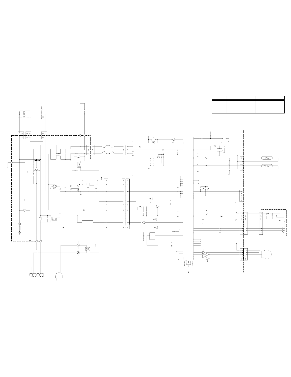
CIRCUIT DIAGRAM
INDOOR UNIT
Thermistor
(Room Temp.)
Thermistor
(Pipe Temp.)
Controller PCB
Display PCB
Terminal
Fan Motor
Capacitor
Stepping Motor
Transformer
Fan Motor
Power Supply PCB
52005.01.07
Page 7
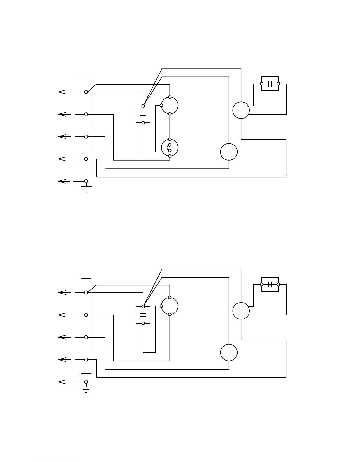
Model : AOY9UFCC
Models : AOY9USCC
AOY12USCC
62005.01.07
TERMINAL
N
L
3
4
COMPRESSOR
CAPACITOR
COMPRESSOR
FAN MOTOR
FAN MOTOR
CAPACITOR
FOUR WAY
VALVE COIL
OVERLOAD
RELAY
WHITE
BLUE
BLACK
BLUE
RED
RED
ORANGE
WHITE
WHITE
DARK GRAY
DARK GRAY
S
R
C
C M
F M
S V
TERMINAL
N
L
3
4
COMPRESSOR
CAPACITOR
COMPRESSOR
FAN MOTOR
FAN MOTOR
CAPACITOR
FOUR WAY
VALVE COIL
WHITE
BLACK
BLACK
RED
RED
ORANGE
WHITE
WHITE
DARK GRAY
DARK GRAY
S
R
C
C M
F M
S V
Page 8
CONTROLLER PCB ASSY (MAIN PCB)
ASY9USCCW : K02DE-0400HSE-C1
ASY12USCCW : K02DE-0401HSE-C1
7
INDOOR PCB CIRCUIT DIAGRAM
2005.07.27
Jumper wire configurations
Switch Function ON/Linked OFF/Open
JP1 Heating compensation +4 +2
JP2 Cooling compensation 0 -2
JP3 Auto restart enable disable
JP4 Custom code A B
5V
5V
R20 - R23
10K <1/10W> x 4
5V
R8
10K
<1/10W>
C9
0.01
<R>
C7
10/
25V
+
R7 4.7K
<1/8W>
R6 1.0K
<1/8W>
C8
0.1
<F>
I C4-6 uLN2003
I C4-5 uLN2003
Q3
DTC124EUA
Q1
DTC124EUA
5V
5V
5V
C11
0.1
<F>
R12
10K
<1/10W>
I C2
BR93LC46
EEPROM
L1
X1
CST8.38MHz
12V
R19
10K
<1/10W>
C16
1000P
<R>
5V
R17 330 <1/10W>
R16 330 <1/10W>
R15 330 <1/10W>
12V
R8 47
<1/10W>
C21
0.1
<F>
C22
0.1
<F>
R24 390
<1/10W>
R25 390
<1/10W>
C25
0.1
<F>
5V
R28 10K
<1/10W>
C27
0.1
<F>
5V
MANUAL AUTO
SWITCH
SW1
R29
10K
<1/10W>
5V
R27 10K
<1/10W>
(1%)
R26 49.9K
<1/10W>
(1%)
I C3
BD1742G
RESET
2
1
5
3
4
R30 1.0K
<1/10W>
I C4-1 uLN2003
I C4-4 uLN2003
I C4-3 uLN2003
I C4-2 uLN2003
R33 10K
<1/10W>
I C4-7 uLN2003
CN6
B8B-PH-K-S
12V
12V
5V
C108
0.1
<F>
12V
I C101
7805
D103
1SR139
+
I O
G
Q101
KSD880
+
D104
MTZJ15B
R102 1.0K
<1/2W>
+
C109
10/50V
C105
2200
/35V
R101
10K
<1/2W>
D105 - D108
1N4007
12V
SSR103
PR3BMF11YSZ
VA102
470V
CN101 B3P5-VH-B
R103 100
<1/2W>
C111
0.1
C104
0.1
L101
SS11V-10062
W105
W106
5V
5V
C1
0.1
<F>
R1
10K
<1/10W>
CN8 S3P-VH
12V
R14 10K
<1/10W>
BZ1
PKM13EPY-4000
B Z
Q2
DTC124EUA
C2
0.1
<F>
5V
R2 1.0K <1/10W>
1
2
3
9
1
31614
8
15
13
4
2
2
33
32
X1 X2
48
47
46
45
49
50
51
52
5
6
7
35
11
12
38
13
19
29
25
24
28
8
44
37
14
15
16
43
27
10
20
26
23
22
30
9
34
21
4
36
1
2
3
42
41
40
39
17
18
31
P57
RESET
P11
P10
XT2
P25
P36
P03
P35
P34
P00
P56
P55
P54
P47
P46
P45
P44
P43
P42
P41
P40
P75
P02
P20
P21
P22
P23
AVDD
VDD0
VDD1
AVREF
P12
P13
XT1
VSS0
VSS1
AVSS
P53
P01
P50
P51
P52
P73
P70
P71
P72
P23
P24
I C
CN5 53325-0510
LOUVER
CN5-8 YELLOW
CN5-10 BLUE
CN5-9 PINK
CN5-7 ORANGE
CN5-6 RED
UL1061 AWG25 x 5
M
5V
CN4 B6B-PH-K-S
R3, R34, R5, R35
10K <1/10W> x 4
JP1
JP4
JP3
JP2
1
2
3
123
611
512
10 7
1
2
3
7
8
4
6
5
VCC
DO
TEST
GND
CS
SK
D I
NC
12V
12V
12V
K103
G4A-1A-E-PS
3 2
4
1
BROWN
SSR102
S202TY2
C110
4700P
VA103
470V
VA101
470V
FH102
FH101
F101
T 3.15A - 250V
W102
BLUE
W103
BLACK
W104
RED
N
L
3
4
TERMINAL BOARD
UL1015 AWG14 WHITE
UL1015 AWG22 BLACK
UL1015 AWG22 BROWN
UL1015 AWG22 BLUE
UL1015 AWG22 RED
UL1015 AWG22 BLUE
EARTH
GREEN / YELLOW
D102
1SR139
K 101
C103
0.1
C101
4700P
C102
4700P
CR101
120/0.2
FAN MOTOR
F M
CN101-1
BLACK
CN101-3
YELLOW
CN101-5
WHITE
CN7-1
RED
CN7-2
WHITE
CN7-3
BLACK
CN2 150-103-86176
CN3 150-503-96077
CN1 B5P-SHF-1AA
CHECKER
CN1-1
CN1-5
CN1-4
CN1-3
CN1-2
CN2-1 BLACK
CN2-2 BLACK
CN3-2 GRAY
CN3-1 GRAY
ROOM TEMPERATURE THERMISTOR
PIPE TEMPERATURE THERMISTOR
UL1061 AWG26 x 6
6
5
4
3
2
1
CN4-6 WHITE
CN4-1 RED
CN4-2 WHITE
CN4-3 WHITE
CN4-4 WHITE
CN4-5 WHITE
OPERATE(RED)
TIMER(GRN)
SWING(ORG)
D201 SLR-325<VC>
D203 SLR-325<DC>
D202 SLR-325<MC>
CN201
R201 47
<1/4W>
+
X201
GP1UM261RK
VCC
DATA
GND
C202
0.1
<F>
C201
47/
10V
INDICATOR PCB
K04AQ-0400HSE-D0
ROOM TEMPERATURE CORRECTION-1
( HEATING OPERATION )
ROOM TEMPERATURE CORRECTION-2
( HEATING OPERATION )
AUTO RESTART
REMOTE CONTROL UNIT
CUSTOM CODE
CN105-1
BLUE
CN105-2
WHITE
CN105-3
WHITE
CN105-4
WHITE
CN105-5
WHITE
CN105-6
WHITE
CN105-7
WHITE
CN105-8
WHITE
CN6-8
CN6-7
CN6-6
CN6-5
CN6-4
CN6-3
CN6-2
CN6-1
UL1061 AWG26 x 8
CN105
PHR-8
K101
JZC-43F/012-HS
W101
E GREEN
UL1015 AWG22
GREEN
POWER TRANSFORMER
EZ-030HSE-T
THERMAL FUSE
PRIMARY SECONDARY
CN102 B2P3-VH-B
CN104 B2B-XH-AM
CN103 B2B-XASK-1-A
CN102-3 PURPLE
CN102-1 PURPLE
CN104-1 RED
CN104-2 RED
CN103-2 GRAY
CN103-1 GRAY
UL1015 AWG20 ORANGE
UL1015 AWG20 ORANGE
FAN CAPACITOR
7.0uF
POWER SUPPLY PCB
K04AQ-0400HSE-P0
C106
R105
POWER SOURCE
220V / 240V
50Hz
R104
I C 1
uPD780024ASGB
-X22-8ET-A
Page 9

ERROR DISPLAY
operation
timer
Error contents Error contents
thermistor
0.5 second
2 times
room temp. thermistor error
0.5 second
2 times
heat exchanger thermistor error
0.5 second
3 times
control unit
0.5 second
4 times
MANUAL AUTO button error
(indoor unit )
0.5 second
2 times
power source Hz decision error
0.5 second
4 times
fan motor
0.5 second
6 times
0.1 second
0.1 second
0.1 second
0.1 second
Indication :
When an error happens, first indication is "Large division indication".
Indication is switched by pushing TEST OPERATION button between "Large" and "Small".
0.1 second
0.1 second
0.1 second
0.1 second
0.1 second
0.1 second
0.1 second
lock error
(indoor unit)
0.5 second
2 times
r.p.m. error
model distinction error
0.5 seond
3 times
LED flashing
operation
timer
LED flashing
Small division indicationLarge division indication
82004.11.30
Page 10
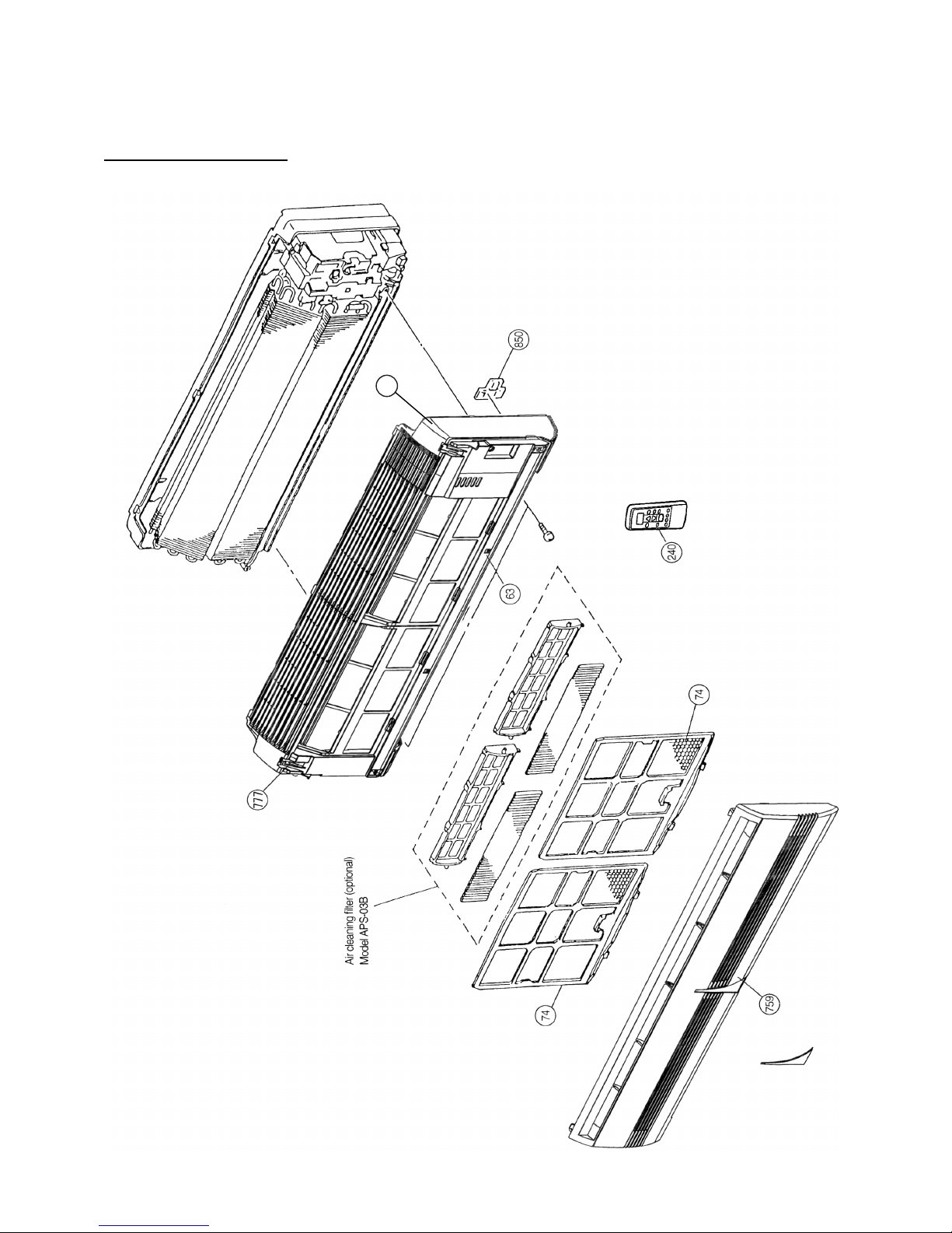
DISASSEMBLY ILLUSTRATION
Models : ASY9USCCW
ASY12USCCW
92004.11.30
777
Page 11
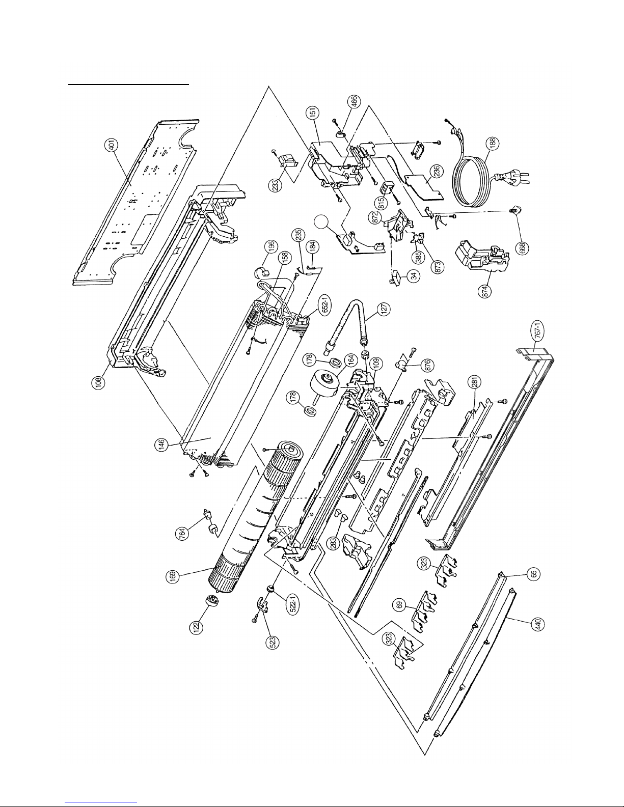
385
Models : ASY9USCCW
ASY12USCCW
102004.11.30
Page 12

Model : AOY9USCC
112006.01.23
999
Page 13

Model : AOY9UFCC
122006.01.23
412
999
Page 14

985
986
Model : AOY12USCC
132006.01.23
999
Page 15
When you order parts, please make a photocopy of this page
and fill the number of the parts in the "Order" column.
INDOOR UNIT
PARTS LIST
Ref.
No.
Description
34 Capacitor (Fan Motor) 9900089061 9900089061
63 9312417032 9312417063
65 Flow Control Panel-Z 9306058012 9306058012
69 9306055028 9306055028
74
Louver-A
Filter 9305444014 9305444014
108 9309755062 9309755062
109 9306052027 9306052027
122 9303066010 9303066010
127 Drain Hose Assy 9305550029 9305550029
146 9330144019 9330144019
151
Base
Casing
Shaft Holder -B
Evaporator Assy
Control Box 9330007017 9330007017
158 Connecting Pipe Assy 9306416010 9306416010
164 Fan Motor Assy-IN 9601171010 9601171010
169 Cross-Flow Fan Assy 9307836015 9307836015
178 9601302018 9601302018
184 313728262708 313728262708
188 Power Cord Assy 9702595043 9702595043
196 313035356905 313035356905
233 9900028015 9900028015
235
Motor Cushion -M
Thermistor Sping
Clamp SKB-150
Power Transformer
Thermistor Assy -Pipe 9702039059 9702039059
236 Controller PCB Assy 9706046015 9706046022
(K02DE-0400HSE-C1) (K02DE-0401HSE-C1)
240 Remote Control Unit 9312058020 9312058020
Part No.
401 Wall Hook Bracket 9304358008 9304358008
440
Flow Control Panel-U 9306057015 9306057015
466 313714328805 313714328805
522-1
Clamp NK-4N
Gear-A 9306062002 9306062002
523
Gear Bracket 9306407001 9306407001
652-1 Thermistor Holder Pipe 313714262805 313714262805
668
313681304205 313681304205
759
9330001015 9330001015
764 Drain Cap Assy 9304150008 9304150008
777
9306755010 9306755010
815 9900040048 9900040048
850
9330003019 9330003019
872 9330009011 9330009011
873 9330014015 9330014015
874
Control Box Cover 9330008014 9330008014
876 Step Motor 9900139018 9900139018
ASY9USCCW ASY12USCCW
281
Clamp Metal (Pipe) 9306063009 9306063009
283 9303529010 9303529010
323
Bushing-A
Louver-B 9306056025 9306056025
385
PCB (Power and Indicator) 9706039017 9706039017
767-1
Screw w/Washer
Intake Grill -A
Terminal
Window (Receiver
Indicator Case
Lamp Cover
Bottom Cover -A 9330004016 9330004016
Clamper (Grille)
Panel (Front) Total Assy
877 Face Panel (Front)-A 9330005044 9330005044
142005.07.27
Page 16

When you order parts, please make a photocopy of this page
and fill the number of the parts in the "Order" column.
AOY9USCC AOY9UFCC
OUTDOOR UNIT
Ref.
No.
Description
4 9308468017
5 Cabinet Front Panel, Plastic 9306016012
7
Emblem-Rear
Connector Cover 9306018016
9 Cabinet Rear Panel, Plastic 9306017019
12 Base Assy, Painted 9304806042
13 9312863013
14
3-Way Valve
2-Way Valve 9312862016
16 9309104020
32 Control Box Metal 9306475024
34 Capacitor (Fan Motor) 9900089023
37 9307588068
38 Clamp Metal (Capacitor) 313468061808
39
Condenser Assy
Capacitor (Running)
Propeller Fan 9306565015
41 Fan Motor Assy-Out 9307095016
42 9306021016
46 9311012016
62 Wire Assy (Shield)-A 9305791026
48
Bracket (Motor)
Compressor Assy
Fan Ring 9306019020
Part No.
365 9306020026
412 Terminal Gasket (For Comp.) 9351505011
674 Screw, SUS410T +5014 9305848010
688 Screw w/Washer 313681304205
Ref.
No.
Description
Part No.
Bracket (Valve)
9308468017
9306016012
9306018016
9306017019
9304806042
9312863013
9312862016
9309104020
9306475024
9900089023
9307588013
313468061808
9306565015
9307095016
9306021016
9314429019
9305695027
9306019020
230 9311143000
343 9970003011
344 9900162016
Overload Relay
Solenoid Coil
4-Way Valve
----9970003011
9900162016
9306020026
9314432002
9305848010
313681304205
9301102000
9301143003
765 Drain Pipe (L-type)
766 Drain Pipe Packing
781 9312680016
815 9306488017
Rubber Cushion
Terminal-4P
9301102000
9301143003
9312680016
9306488017
935 9306473006
Control Box Cover Metal
982 Cord Clamp, Plastic 9302271002
Reinforcement Plate
942-2 Control Box Cover-B Metal 9305975006
942 9306476007
9306473006
9302271002
9305975006
9306476007
138 Separate Wall Metal 9306474003
195 313361275805
196-2
Clamp SKB-100
Clamp SKB-3MC 9305335008
9306474003
313361275805
9305335008
985 Special Nut w/Washer 9304902003
986 Special Washer 9304903000
A Screw (with Inner Washer) 9357297002
BR Sheet 180x180x T2 9305039067
9304902003
9304903000
999 Capillary Assy 9312868001 9312868001
9357297002
9305039067----
AOY12USCC
4
5
Cabinet Front Panel, Plastic
7
Emblem-Rear
Connector Cover
9
Cabinet Rear Panel, Plastic
12
Base Assy, Painted
13
14
3-Way Valve
2-Way Valve
16
BR Sheet 60x100x T5 9305039012
BR Sheet 40x80x T5 9305039043
32
Control Box Metal
34
Capacitor (Fan Motor)
37
38
Clamp Metal (Capacitor)
39
Condenser Assy
Capacitor (Running)
Propeller Fan
41
Fan Motor Assy-Out
42
46
51
Special Nut M5
55
Special Nut M6
109
138
Separate Wall Metal
187
9308468017
9306386016
9306119010
9306385019
9306118020
9312865017
9312864010
9308459039
9308561022
9900089030
9307588013
313468061808
9305538003
9307715020
9305536016
9311133018
Bracket (Motor)
Compressor Assy
9307091001
313252257701
98
Fan Ring 9305581023
9307090004
9305971008
313361271706
196
313035356905
195
313361275805
230
343
344
365
412
Terminal Gasket (For Comp.)
674
Screw, SUS410T +5014
688
Screw w/Washer
765
Drain Pipe (L-type)
766
Drain Pipe Packing
815
Reinforcement(Cabinet TOP) 9305973002
916
942-1
Control Box Cover-A Metal
982
Cord Clamp, Plastic
Terminal-4P
Noise Insulation -A
A
Screw (with Inner Washer)
Screw (with Spring Washer)
B
9357297002
0700179013
9312899005
9970003011
9900162016
9306748012
9351121006
9305848010
313681304205
9301102000
9301143003
9306488017
9306362003
9308562012
942-2
Control Box Cover-B Metal 9305975006
946
Inlet Pipe 9306401009
9302271002
999 Capillary Assy 9312873005
935-1
Reinforcement -F (Cabinet Top) 9306123000
935-2
196-2
Terminal Cover
Clamp No.1219
Clamp SKB-150
Clamp SKB-100
Overload Relay
Solenoid Coil
4-Way Valve
Bracket (Valve)
Clamp SKB-3MC 9305335008
BR Sheet 180x180x T2 9305039067
----
----
----
152006.01.23
Page 17

Name and Shape Part No.
9304358008
9312058020
0600185534
9308117007
0700076046
9303029015
Remote control
unit
Battery (penlight)
Cloth tape
Drain pipe
(Including drain packing)
Tapping screw
Wall hook bracket
STANDARD
ACCESSORIES
( 4 x 25 )
O
162004.12.01
Page 18

0309G2374
 Loading...