

Page 1

S PLIT TY PE R OOM A IR
CON DIT ION E R
W A L L M O U N T E D
ty p e
Models
Indoor unit Outdoor unit
ASY14FSBCW AOY14FSBC
ASY14USBCW AOY14USBC
CONTENTS
preliminary
SPECIFICATIONS
. . . . . . . . . . . . . . . . . . . . . . . . . . . . . . .
1
OUTLINE AND DIMENSIONS
. . . . . . . . . . . . . . . . . . . .
3
REFRIGERANT SYSTEM DIAGRAM
. . . . . . . . . . . . .
5
ERROR DISPLAY
. . . . . . . . . . . . . . . . . . . . . . . . . . . . . . .
8
CIRCUIT DIAGRAM
. . . . . . . . . . . . . . . . . . . . . . . . . . . . .
6
PCB CIRCUIT DIAGRAM
. . . . . . . . . . . . . . . . . . . . . . . . .
10
DISASSEMBLY ILLUSTRATION
. . . . . . . . . . . . . . . . . . .
11
PARTS LIST
. . . . . . . . . . . . . . . . . . . . . . . . . . . . . . . . . . .
15
ACCESSORIES
. . . . . . . . . . . . . . . . . . . . . . . . . . . . . . . . .
18
Page 2
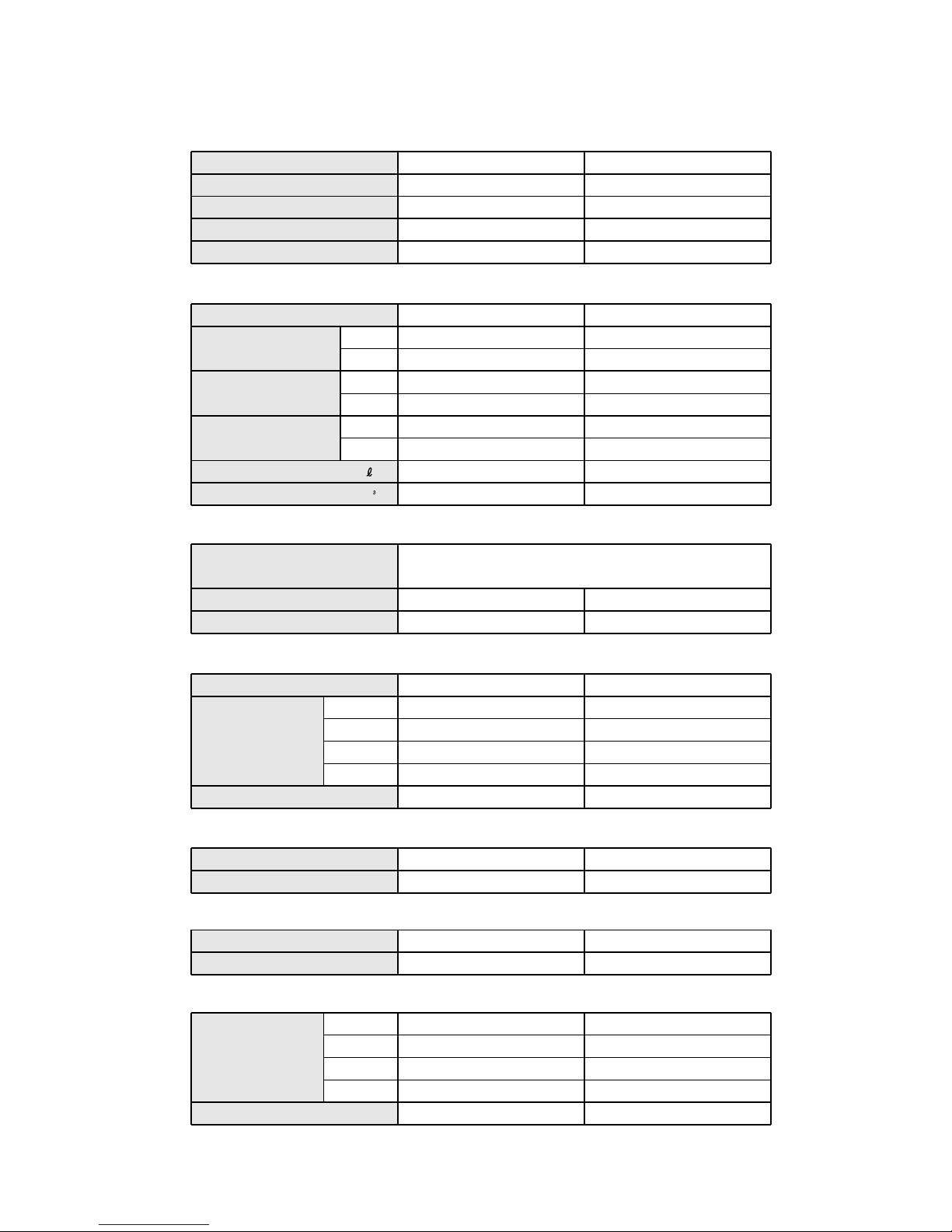
COOLING COOLING & HEATING
ASY14FSBCW ASY14USBCW
AOY14USBC AOY14USBC
2.90 3.70
------ 4.00
230V 50Hz 230V 50Hz
COOL
3.7 5.0
HEAT ------ 4.6
COOL
0.84 1.13
HEAT ------ 1.04
COOL 3.45 3.27
HEAT ------ 3.85
1.3 1.9
COOL 600 COOL 700 HEAT 675
GK113PAC 220, 230, 240V / 50Hz 802-360-45B 220-240V / 50Hz
900 1100
(V)
230 230
COOL 1250 COOL 1450 HEAT 1400
COOL 1100 COOL 1250 HEAT 1230
COOL 1000 COOL 1050 HEAT 1060
COOL 800 COOL 850 HEAT 900
730 820
275 x 790 x 215 275 x 790 x 215
535 x 695 x 250 535 x 780 x 250
POWER SOURCE
AIR CIRCULATION-Hi
Hermetic type, Permanent split condenser,
2 pole, Single phase, Induction motor, Scroll
INPUT WATTS
E.E.R
MOISTURE REMOVAL
SPECIFICATIONS
RUNNING CURRENT
12004.08.17 preliminary
TYPE
INDOOR UNIT
OUTDOOR UNIT
COOLING CAPACITY
(kW)
(A)
(m /hr)
( /hr)
ELECTRICAL DATA
COMPRESSOR
DIMENSIONS
TYPE
DISCRIMINATION
REFRIGERANT
R410A (g)
INDOOR UNIT
H x W x D (mm)
OUTDOOR UNIT
H x W x D (mm)
HEATING CAPACITY
(kW)
12 / 9 12 / 9
33 / 30 37 / 35
WEIGHT
INDOOR UNIT
GROSS / NET (kg)
OUTDOOR UNIT
GROSS / NET (kg)
(kW)
(kW/kW)
Hi-SPEED
MED-SPEED
LO-SPEED
S-LO
POWER SUPPLY
OUTDOOR UNIT
INDOOR UNIT
(r.p.m)
FAN MOTOR
(r.p.m)
Hi-SPEED
MED-SPEED
LO-SPEED
S-LO
OUTDOOR UNIT
INDOOR UNIT
(dB)
NOISE LEVEL
(dB)
COOL 40 COOL 45 HEAT 43
COOL 36 COOL 41 HEAT 39
COOL 32 COOL 35 HEAT 34
COOL 27 COOL 29 HEAT 28
COOL 45 COOL 48 HEAT 49
Page 3

ADDITIONAL CHARGE OF REFRIGERANT (R410A)
(ASY14FSBCW / AOY14USBC)
(ASY14USBCW / AOY14USBC)
Refrigerant suitable for a piping length of 7.5 m is charged in the outdoor unit at the factory.
When the piping is longer than 7.5 m, additional charging is necessary.
For the additional amount, see the table below.
PIPE LENGTH
7.5 m 10 m
ADDITIONAL REFRIGERANT
None 50 g
15 m
150 g
Between 7.5 m and 15 m, when using a connection pipe other than that in the table,
charge additional refrigerant with 20g /1 m as the criteria.
(The maximum length of piping is 15m. If the units are further apart than this, correct
operation can not be guaranteed.)
22004.08.11 preliminary
Page 4

INDOOR UNIT
Unit : mm
DIMENSIONS
790
215
275
32004.08.17 preliminary
Models : ASY14FSBCW, ASY14USBCW
Page 5
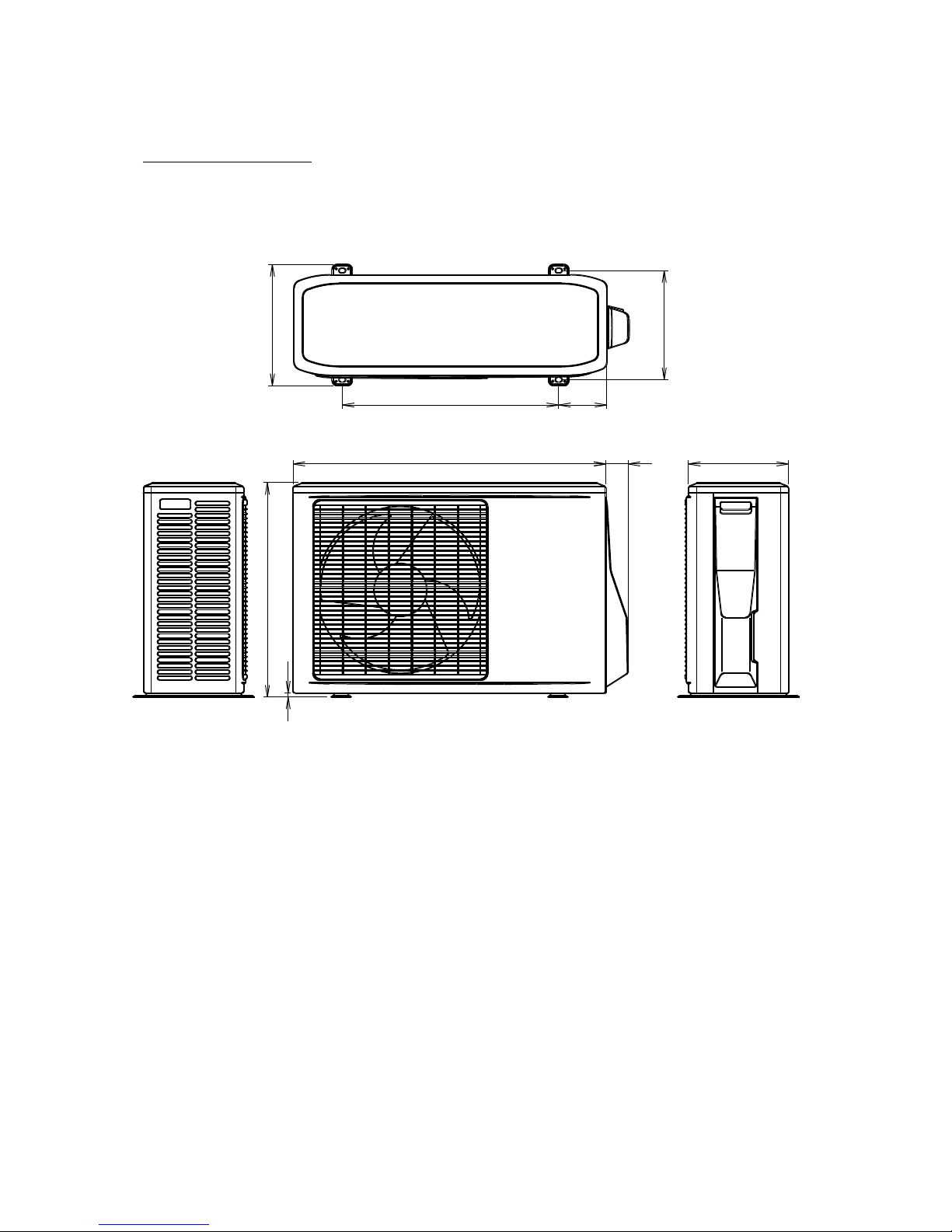
540 120
272
302
780 55
250
535
10
OUTDOOR UNIT
42004.08.17 preliminary
AOY14USBC
Models : AOY14FSBC
Page 6

REFRIGERANT SYSTEM DIAGRAM
Models : ASY14FSBCW / AOY14FSBC
Models : ASY14USBCW / AOY14USBC
Heating
Cooling
(with Charging valve)
Condenser
Dryer
(Flare connection)
Gas pipe (9.52 dia.)
(Flare connection)
(Flare connection)
Liquid pipe (6.35 dia.)
(Flare connection)
[ INDOOR UNIT ]
[ OUTDOOR UNIT ]
[ Connecting pipe ]
Compressor
52004.08.17 preliminary
3-Way valve
4-Way
valve
Capillary tube
or heating and cooling
2-Way valve
Check
valve
Capillary tube for heating
Evaporator
Page 7
62004.08.17 preliminary
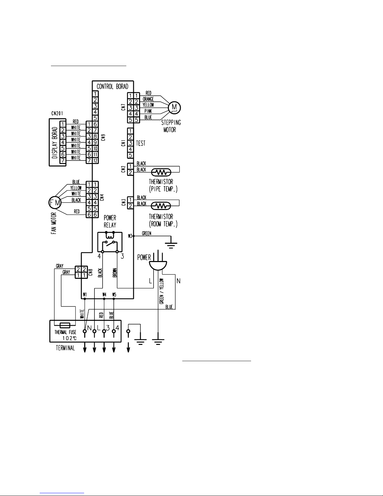
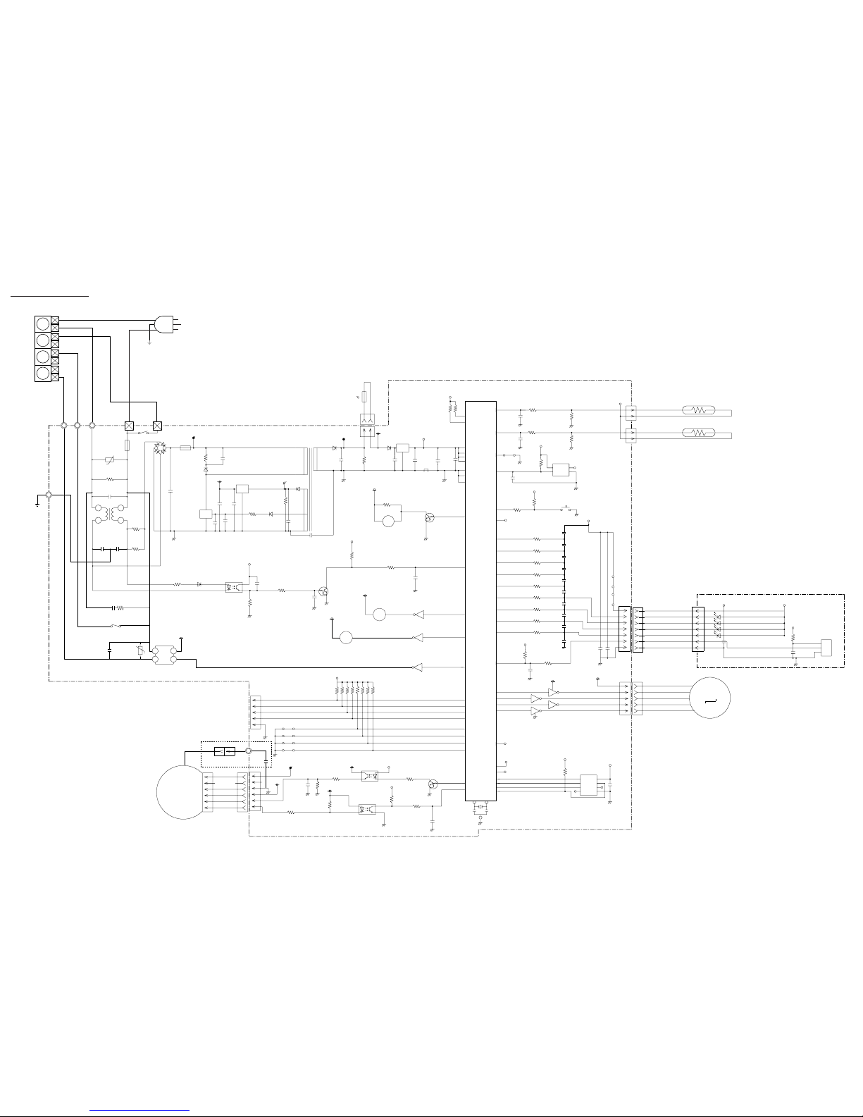
CIRCUIT DIAGRAM
Model : ASY14FSBCW
Model : AOY14FSBC
Page 8
72004.08.17 preliminary
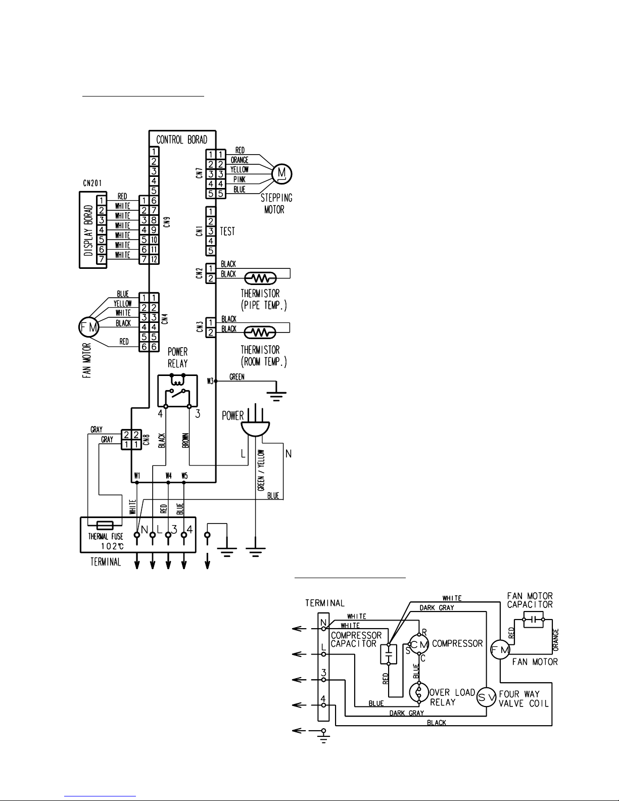
Model : ASY14USBCW
Model : AOY14USBC
Page 9

5V
JM40
JP15
5V
12V
12V
12V
I C4-3
I C4-2
I C4-1
5V
C28
0.01
<B>
R3
10K
<1/10W>
R5 1.0K <1/10W>
R46 - R43, R16 - R19
10K <1/10W>
5V
15V
VM
5V
5V
5V
C8
0.1 <F>
R35 10K
<1/10W>
I C2
S-93C46ADFJ
CS
SK
D1
NC
VCC
D0
TEST
GND
1
2
3
7
8
4
6
5
33 32
X1 X2
43
42
41
40
29
30
11
48
47
46
45
35
52
19
28
31
24
25
P10
AN I 0
P11
AN I 1
I C
RESET
P25
P47
P57
P34
P56
P55
P54
P53
P52
P51
P50
P00
I NTP0
P40
P41
P42
P43
P34
XT1
XT2
P71
P72
P73
P74
37
39
12
13
22
23
16
15
38
14
50
51
49
36
44
34
21
9
27
26
20
10
18
17
P23
P24
VDD0
VDD1
AVREF
AVD0
GND0
AGND
GND1
P75
BUZ
I NTP1
P01
P44
P46
P45
P20
P03
P21
P22
P12
AN I 2
P13
AN I 3
P36
P35
P70
P02
I NTP2
C46
1000P
<R>
Q5
DTC124EUA
5V
R14 330
<1/10W>
5V
R26
10K
<1/10W>
R27 1.0K
<1/10W>
15V
A
A
+
I C10
PS2561-1
<L>
I C12
PS2561-1
<L>
15V
1
2
4
3
3
421
Q4
DTC124EUA
12V
R42 10K
<1/10W>
B Z
BZ1
PKM13EPY-4000-TF01
K 1
14 3
1
3
2
1
2
16
15
I O
G
+
+
+
FL1
BL02RN1
5V
C18
0.1
<F>
C17
10/
25V
C15
0.1
<F>
C14
330/
25V
13.5V
D4
D1F60
I C7
7805
R65
1.8K
<1/4W>
C13
330/
25V
D6
D2FL20U
T1
ETS19AA1PA1AC
D7
D1FL20U
20V
5
3
4
2
9
1
7
R47 100K
<1/10W>
C12
330/
25V
+
D8
D1FL20U
R7 22
<1/4W>
I
G
O
I C13
78M15
123
5V
C52
0.01
C7
0.01
C60
0.01
<B>
C61
0.01
<B>
C6
0.01
Q2
DTC124EUA
R13 1.0K
<1/10W>
R12
10K
<1/10W>
A
R10 56K <RS-2W>
D3
D1F60
I C11
PS2561-1
<L>
1
4
32
15V
D2 1NH42
C5
100/
420V
+
I C5
M I P2E2
VM
C24
330/
25V
3
1
2
SO
CT
DR
C27
0.1
<F>
+
C10
47/
16V
C53
0.1
<F>
+
F2
2.5A
250V
R22
100K
<2W>
D1
GS I B460L
2
3
4
1
K1
G4A-1A
W1
WHITE
BLACK
VA1
470V
F1
3.15A-250V
330K
<1/2W>
C4 0.22
L1
1.3A
R9
2.2
<5W>
CN1
BS5P-SHF-1AA
TEST
CN1-1
CN1-5
CN1-4
CN1-3
CN1-2
CN4
53426-9920
CN4-6
CN4-4
CN4-3
CN4-2
CN4-1
WHITE
YELLOW
BLACK
BLUE
RED
A
R20 6.8K
<1/4W>
C41
100/
16V
R21
4.7K
<1/10W>
R11 820
<1/4W>
(1%)
R8 1.0K
<1/4W>
(1%)
FAN MOTOR F M
M
LOUVER
5V
5V
INDICATOR PCB
EZ-003MWSE-D
5V
R201
47
<1/4W>
+
C202
47/10V
I C201
GP 1UM261RK
C201
0.1 <F>
D204 SLR-325 <ORG>
D201 SLR-325 <RED>
D202 SLR-325 <GRN>
D203 SLR-325 <GRN>
CN9
S07B-ZR-3.4
CN201
JB20-07HG
CN201-1
CN201-7
CN201-6
CN201-5
CN201-4
CN201-3
CN201-2
WHITE
RED
WHITE
WHITE
WHITE
WHITE
WHITE
5V
CN2
2P-SAN
CN3
2P-SCN
ROOM TEMPERATURE THERMISTOR
PIPE TEMPERATURE THERMISTOR
CN2-1 BLACK
CN2-2 BLACK
CN3-2 BLACK
CN3-1 BLACK
5V
R48 10K
<1/10W>
(1%)
R33 49.9K
<1/10W>
(1%)
R4 1.0K
<1/10W>
R34 1.0K
<1/10W>
C35
0.1
<F>
C31
0.1
<F>
R23
5V
R31
10K
<1/10W>
R32 1.0K
<1/10W>
C20
0.1
<F>
R49
100K
<1/10W>
SW1
I C6
S80842
VDD
OUTNCGND
1
2
3
4
+
C51
0.01
<B>
C50
100/16V
R1 47
<1/10W>
R15
10K
<1/10W>
C48
1000P
<R>
CN7
53325-0510
I C4-7
I C4-5
I C4-4
I C4-6
9
8
12
10
1
2
7
11
5
134
6 CN7-3 YELLOW
CN7-2 ORANGE
CN7-1 RED
CN7-4 PINK
CN7-5 BLUE
5V
R25 - R24
10K <1/10W>
I C 1
uPD780024ASGB-X49-8ET-A
CN8
GRAY
GRAY
TERMAL FUSE
102
TIMER SHORT
CLOCK
DATA-OUT
DATA-ON
MODEL EXCHANGE 2
MODEL EXCHANGE 1
REMOTE CONTROL
AUTO RESTART
JM1
JM4
JM3
JM2
CONTROLLER PCB ASSEMBLY ( MAIN PCB )
K02DG-0401WSE-C1
I N D O O R P R I N T E D C I R C U I T B O A R D
C I R C U I T D I A G R A M
Model : ASY14FSBCW
W6
12V
K 2
UL1015 AWG22
GREEN
E
W3
C1
C2
0.01
0.01
R64
2.2
<5W>
GNR
VCC
OUT
GND
R52 330 <1/10W>
R30 330 <1/10W>
R28 330 <1/10W>
1 2
R29 330 <1/10W>
1 2
1 2
1 2
R57 10k <1/10W>
1 2
1
2
3
4
5
6
7
8
11
C72
0.1
<F>
C63
0.1
<F>
R56 10k <1/10W>
1 2
C64
0.1
<F>
R55 10k <1/10W>
1 2
C65
0.1
<F>
R54 10k <1/10W>
1 2
C66
0.1
<F>
R53 10k <1/10W>
1 2
C67
0.1
<F>
C68
0.1
<F>
C69
0.1
<F>
C70
0.1
<F>
C71
0.1
<F>
82004.08.18 preliminary
E
GREEN / YELLOW
N
L
POWER SOURCE
220 / 240V
50Hz
BLUE
BROWN
Page 10
5V
JM40
JP15
5V
12V
12V
12V
I C4-3
I C4-2
I C4-1
5V
C28
0.01
<B>
R3
10K
<1/10W>
R5 1.0K <1/10W>
R46 - R43, R16 - R19
10K <1/10W>
5V
15V
VM
5V
5V
5V
C8
0.1 <F>
R35 10K
<1/10W>
I C2
S-93C46ADFJ
CS
SK
D1
NC
VCC
D0
TEST
GND
1
2
3
7
8
4
6
5
33 32
X1 X2
43
42
41
40
29
30
11
48
47
46
45
35
52
19
28
31
24
25
P10
AN I 0
P11
AN I 1
I C
RESET
P25
P47
P57
P34
P56
P55
P54
P53
P52
P51
P50
P00
I NTP0
P40
P41
P42
P43
P34
XT1
XT2
P71
P72
P73
P74
37
39
12
13
22
23
16
15
38
14
50
51
49
36
44
34
21
9
27
26
20
10
18
17
P23
P24
VDD0
VDD1
AVREF
AVD0
GND0
AGND
GND1
P75
BUZ
I NTP1
P01
P44
P46
P45
P20
P03
P21
P22
P12
AN I 2
P13
AN I 3
P36
P35
P70
P02
I NTP2
C46
1000P
<R>
Q5
DTC124EUA
5V
R14 330
<1/10W>
5V
R26
10K
<1/10W>
R27 1.0K
<1/10W>
15V
A
A
+
I C10
PS2561-1
<L>
I C12
PS2561-1
<L>
15V
1
2
4
3
3
421
Q4
DTC124EUA
12V
R42 10K
<1/10W>
B Z
BZ1
PKM13EPY-4000-TF01
K 1
14 3
1
3
2
1
2
16
15
I O
G
+
+
+
FL1
BL02RN1
5V
C18
0.1
<F>
C17
10/
25V
C15
0.1
<F>
C14
330/
25V
13.5V
D4
D1F60
I C7
7805
R65
1.8K
<1/4W>
C13
330/
25V
D6
D2FL20U
T1
ETS19AA1PA1AC
D7
D1FL20U
20V
5
3
4
2
9
1
7
R47 100K
<1/10W>
C12
330/
25V
+
D8
D1FL20U
R7 22
<1/4W>
I
G
O
I C13
78M15
123
5V
C52
0.01
C7
0.01
C60
0.01
<B>
C61
0.01
<B>
C6
0.01
Q2
DTC124EUA
R13 1.0K
<1/10W>
R12
10K
<1/10W>
A
R10
56K
<RS-2W>
D3
D1F60
I C11
PS2561-1
<L>
1
4
32
15V
D2 1NH42
C5
100/
420V
+
I C5
M I P2E2
VM
C24
330/
25V
3
1
2
SO
CT
DR
C27
0.1
<F>
+
C10
47/16V
C53
0.1
<F>
+
F2
2.5A
250V
R22
100K
<2W>
D1
GS I B460L
2
3
4
1
K1
G4A-1A
W1
WHITE
BLACK
VA1
470V
F1
3.15A-250V
330K
<1/2W>
C4 0.22
L1
1.3A
R9
2.2
<5W>
E
GREEN / YELLOW
CN1
BS5P-SHF-1AA
TEST
CN1-1
CN1-5
CN1-4
CN1-3
CN1-2
CN4
53426-9920
CN4-6
CN4-4
CN4-3
CN4-2
CN4-1
WHITE
YELLOW
BLACK
BLUE
RED
A
R20 6.8K
<1/4W>
C41
100/
16V
R21
4.7K
<1/10W>
R11 820
<1/4W>
(1%)
R8 1.0K
<1/4W>
(1%)
FAN MOTOR F M
N
L
M
LOUVER
5V
5V
INDICATOR PCB
EZ-003MWSE-D
5V
R201
47
<1/4W>
+
C202
47/10V
I C201
GP 1UM261RK
C201
0.1 <F>
D204 SLR-325 <ORG>
D201 SLR-325 <RED>
D202 SLR-325 <GRN>
D203 SLR-325 <GRN>
CN9
S07B-ZR-3.4
CN201
JB20-07HG
CN201-1
CN201-7
CN201-6
CN201-5
CN201-4
CN201-3
CN201-2
WHITE
RED
WHITE
WHITE
WHITE
WHITE
WHITE
5V
CN2
2P-SAN
CN3
2P-SCN
ROOM TEMPERATURE THERMISTOR
PIPE TEMPERATURE THERMISTOR
CN2-1 BLACK
CN2-2 BLACK
CN3-2 BLACK
CN3-1 BLACK
5V
R48 10K
<1/10W>
(1%)
R33 49.9K
<1/10W>
(1%)
R4 1.0K
<1/10W>
R34 1.0K
<1/10W>
C35
0.1
<F>
C31
0.1
<F>
R23
5V
R31
10K
<1/10W>
R32 1.0K
<1/10W>
C20
0.1
<F>
R49
100K
<1/10W>
SW1
I C6
S80842
VDD
OUTNCGND
1
2
3
4
+
C51
0.01
<B>
C50
100/16V
R1 47
<1/10W>
R15
10K
<1/10W>
C48
1000P
<R>
CN7
53325-0510
I C4-7
I C4-5
I C4-4
I C4-6
9
8
12
10
1
2
7
11
5
134
6 CN7-3 YELLOW
CN7-2 ORANGE
CN7-1 RED
CN7-4 PINK
CN7-5 BLUE
5V
R25 - R24
10K <1/10W>
I C 1
uPD780024ASGB-X49-8ET-A
CN8
GRAY
GRAY
TERMAL FUSE
102
TIMER SHORT
CLOCK
DATA-OUT
DATA-ON
MODEL EXCHANGE 2
MODEL EXCHANGE 1
REMOTE CONTROL
AUTO RESTART
JM1
JM4
JM3
JM2
CONTROLLER PCB ASSEMBLY ( MAIN PCB )
K02DG-0400HSE-C1
Model : ASY14USBCW
POWER SOURCE
220 / 240V
50Hz
BLUE
BROWN
W6
12V
K 2
UL1015 AWG22
GREEN
E
W3
GNR
C2
C3
0.01
0.01
R64
2.2
<5W>
VCC
OUT
GND
R52 330 <1/10W>
R30 330 <1/10W>
R28 330 <1/10W>
1 2
R29 330 <1/10W>
1 2
1 2
1 2
R57 10k <1/10W>
1 2
1
2
3
4
5
6
7
8
11
C72
0.1
<F>
C63
0.1
<F>
R56 10k <1/10W>
1 2
C64
0.1
<F>
R55 10k <1/10W>
1 2
C65
0.1
<F>
R54 10k <1/10W>
1 2
C66
0.1
<F>
R53 10k <1/10W>
1 2
C67
0.1
<F>
C68
0.1
<F>
C69
0.1
<F>
C70
0.1
<F>
C71
0.1
<F>
BLU
RED
W5
W4
3
4
12V
SSR1
G3MC-202P-VD
DC12V
+
-
VA2
470VC10.01
K2
G5NB-1A
RC1
RE1202
1
2
3
4
92004.08.18 preliminary
Page 11
102004.08.17 preliminary
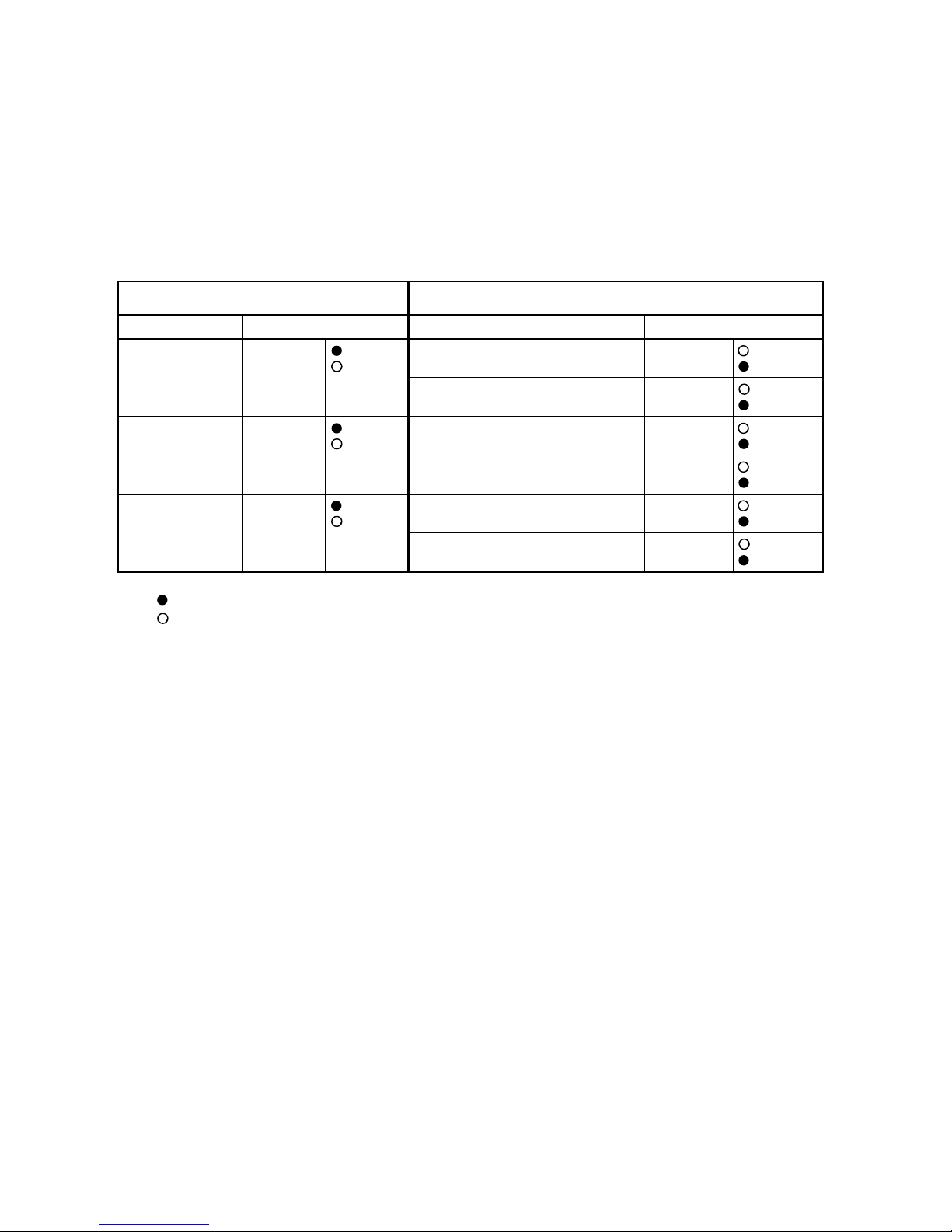
ERROR DISPLAY
Troubleshooting check table
Operation lamp
: Red lamp
Timer lamp : Green lamp
Error contents Error contents
thermistor error RED lamp (2 times) thermistor error (room temp.) RED lamp
Green lamp Green lamp (2 times)
thermistor error (heat exchanger)
RED lamp
Green lamp
RED lamp
Green lamp
RED lamp
Green lamp
(3 times)
RED lamp
Green lamp (2 times)
RED lamp
Green lamp (3 times)
control unit error RED lamp (4 times) MANUAL AUTO button error
(indoor unit) Green lamp (2 times)
power source Hz decision error
(4 times)
fan motor error RED lamp (6 times) lock error
(indoor unit) Green lamp
rpm error
: 0.5s ON/OFF repeated
: 0.1s ON/OFF repeated
LED indication LED indication
Small division indicationLarge division indication
Page 12

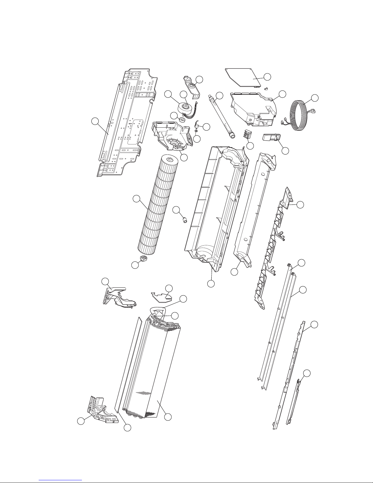
1
Indoor unit
DISASSEMBLY ILLUSTRATION
112004.08.17 preliminary
4
1
3
3
2
1
51
Page 13
45
22
17
18
44
32
49
26
28
40
39
27
29
24
46
25
48
25
36
37
52
31
20
122004.08.17 preliminary
21
23
19
30
43
42
38
33
Page 14

Model : AOY14FSBC
132004.08.17 preliminary
Page 15
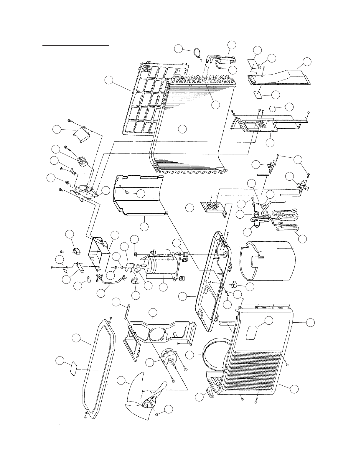
Model : AOY14USBC
142004.08.17 preliminary
156
28
79
19
16
137
176
226
91
146
145
48
126
33
232
125
25
129
128
158
30
2
229
159
233
96
236
20
174
216
95
131
124
92
112
150
167
192
118
208
151
104
155
81
228
148
227
231
140
54
210
230
221
33
149
17
87
18
235
Page 16

W hen yo u o rder par ts, p leas e m ake a photo copy o f this pa ge
an d fi ll the num ber of the pa rts i n the "Order " c olum n.
INDOOR UNIT
PARTS LIST
Ref.
No.
Description
Ord.
Q'ty
1 9311027010
2
Flow Control Panel-Z
9309999039
3 9306755010
4 9312100026
9 9311784036
20 9309994003
21 9312112074
23 9309988002
24 9307836015
25 9306274009
26 Clamper (Motor) 9310102008
27
Fan Motor Assy-IN
9306628017
28
Cross-Flow Fan Assy
9310357019
29 9304150008
30 9311946014
31 9309996014
32
Power Cord Assy
9311863014
33 9313099015
36 9311497011
37
38
Display PCB Assy
Pipe Thermister
39
Remote Control Unit
Controller PCB Assy
Insulation (Pipe) -E
Holder (Evaporator) -L
Holder (Evaporator) -R
Step Motor
Front Panel
Intake Grill
Emblem-A
Casing Assy
Shaft Holder-C Assy
Evaporator Total Assy
Cover (Switch)
Joint Pipe Ass y E
Box (Switch)
Wire Clamper
Motor Cushion-B
Gear-A
Air Filter
Part No.
46
Water Seal
Air Seal
9312912018
48
Flow Control Panel-U
9310611005
51
9701955077
52
9900139025
Bracket Panel
9601351016
9371190174
9310001004
Terminal
9309991026
9309992023
Drain hose Assy
Drain Cap Assy
9900157012
ASY14FSBCW ASY14USBCW
40
9304607007
42
9309982017
43
9705611016
(K02DG-0400HSE-C1)
44
9309983014
Cover(Casing)-B
9705039025
9702039073
Clamper(Grille)
152004.08.11 preliminary
Page 17

When you order parts, please make a photocopy of this page
and fill the number of the parts in the "Order" column.
Q'ty
AOY14FSBC AOY14FSBC
OUTDOOR UNIT
Ref.
No.
Description
Part No.
Ref.
No.
Description
Ord.
Q'ty
Ord.
Part No.
162004.08.17 preliminary
Page 18

When you order parts, please make a photocopy of this page
and fill the number of the parts in the "Order" column.
Q'ty
AOY14USBC AOY14USBC
OUTDOOR UNIT
Ref.
No.
Description
2 0700179013
3
Screw 301171134250
Screw, Taptite (Earth)
Clamp No.1219
Clamp SKB-100
Capacitor Clamp
17
313361275805
18
313468061808
19
Screw with Washer
313681304205
BR Sheet 30x120x T7
9305039036
BR Sheet 20x120x T5
30
Drain Pipe Assy
9303029015
20
Air Pipe
Special Nut with Washer
9300895002
25 Grip
9302061016
33 Heat Insulation (Motor) 9304859000
35 9304902003
Label (Warning)
81
Label (origin) 9306536015
87
Running Capacitor 9307588068
91
Special Nut 9307615016
9307835001
9308037008
104 9308442000
112 Label (Warning) 9308567017
124
16
313361271706
28 Cord Clamp
9302271002
9305039104
9305039067
48 9305870028
95 Hex Bolt
96 Screw
U-Pipe Y
Fan Ring
Panel Rear
125 9309876019
9309870024
Part No.
Ref.
No.
Description
Ord.
Q'ty
Ord.
151 9310980019
155 9312587018
156
Cover (Terminal)
9311021018
158 9311043003
159 9311045007
118 9309608016
9310973011
9311083016
9311105008
9311347026
131 9310084014
167
Label
170
Cabinet Seal-B
9311096009
171
Cabinet Seal-A
9311097006
172 9311099000
9311480013
174
Entrance Pipe
Top Seal-A
Bracket (Terminal)
176
169
Top Seal-B
Discharge Pipe
Emblem-Rear
Cover (Switch)
Condenser
Protection Net
2-Way Valve
Sealed Tube
Clamp
9311088004
Part No.
149
Noise Insulation-C
Compressor Ass y
177
150 9310979013
BR Sheet 180x180x T2
128 Cabinet, Painted
Propeller Fan
9309928053
129 Blow Grill 9309929012
54
Bracket (Motor) 9306047030
9306488017
9310229026
140 9310248065
145 Panel (Top), Painted
Base, Painted
9310338063
146
126 9309909014
79
Terminal
137 BCT (Valve)
Separator
Label (Outer Circuit)
92
9307659010
9310969014
148 Box (Switch) 9310971024
192
Dryer
9312056002
211
OCR
9373129011
213
Capillary Assy
9313715014
9313060015
9351522018
210 9313741013
216
3-Way Valve Assy
224
Washer
9359425014
9359428015
226
Rubber Sheat-A
227
Terminal Washer
Nut
230
Terminal Gasket
9362004008
231
Terminal Cover
9351120009
9900162016
9900089030
228 9359430018
233
4-Way Valve
9601541011232
Motor, Induct
235
Running Capacitor
9970003011236 S olenoid
9911642015186
Noise Insulation-F
172004.08.17 preliminary
Page 19

182004.08.17 preliminary
Name and Shape Part No.
0700076046
9310519004
0600185534
9371190174
For USBCW
9310001004
Remote control
unit
Battery (penlight)
Cloth tape
Tapping screw
(4 x 25)
Wall hook bracket
STANDARD ACCESSORIES
Page 20

0408G2649
 Loading...