

Page 1

SPLIT TYPE
ROOM AIR CONDITIONER
WALL MOUNTED
type
Models Indoor unit Outdoor unit
ASU9RLQ
ASU12RLQ
ASU18CL
ASU18RL
AOU9RLQ
AOU12RLQ
AOU18CL
AOU18RL
INVERTER
SERVICE
INSTRUCTION
R410A
Page 2

CONTENTS
1. SPECIFICATION
ASU9/12RLQ, AOU9/12RLQ..........................................................................................
2. DIMENSIONS
ASU9/12RLQ, AOU9/12RLQ, ASU18C/RL, AOU18C/RL...............................................
ASU18C/RL, AOU18C/RL...............................................................................................
3. REFRIGERANT SYSTEM DIAGRAM
ASU9/12RLQ, AOU9/12RLQ..........................................................................................
ASU18C/RL, AOU18C/RL...............................................................................................
4. CIRCUIT DIAGRAM
ASU9/12RLQ, AOU9/12RLQ...........................................................................................
ASU18C/RL, AOU18C/RL...............................................................................................
5. DESCRIPTION OF EACH CONTROL OPERATION
1. COOLING OPERATION..............................................................................................
3. DRY OPERATION......................................................................................................
2. HEATING OPERATION..............................................................................................
5. INDOOR FAN CONTROL...........................................................................................
4. AUTO CHANGEOVER OPERATION.........................................................................
7. LOUVER CONTROL...................................................................................................
6. OUTDOOR FAN CONTROL.......................................................................................
9. TIMER OPERATION CONTROL................................................................................
8. COMPRESSOR CONTROL........................................................................................
11. TEST OPERATION CONTROL..................................................................................
10. ELECTRONIC EXPANSION VALVE CONTROL........................................................
13. FOUR-WAY VALVE EXTENSION SELECT...............................................................
12. PREVENT TO RESTART FOR 3 MINUTES ( 3 MINUTES ST )................................
15. MANUAL AUTO OPERATION ( Indoor unit body operation ).....................................
14. AUTO RESTART........................................................................................................
16. FORCED COOLING OPERATION............................................................................
18. COIL DRY OPEARTION CONTROL..........................................................................
17. COMPRESSOR PREHEATING..................................................................................
19. DEFROST OPERATION CONTROL..........................................................................
21. VARIOUS PROTECTIONS.........................................................................................
20. OFF DEFROST OPERATION CONTROL..................................................................
01-01
02-01
02-02
03-01
03-02
04-01
04-02
05-01
05-02
05-03
05-04
05-05
05-07
05-08
05-09
05-10
05-12
05-12
05-12
05-12
05-13
05-13
05-13
05-13
05-14
05-16
05-17
05-12
Page 3

6. REFRIGERANT CAUTION -R410A-
1. R410A TOOLS............................................................................................................
3. PRECAUTION FOR SERVICING...............................................................................
2. PRECAUTION FOR INSTALLATION.........................................................................
5. DEFFERENCE FROM CONVENTIONAL MODEL(R22) AND PRECAUTIONS........
4. NEW REFRIGERANT R410A.....................................................................................
7. TROUBLE SHOOTING
1. WHEN THE UNIT DOES NOT OPERATE AT ALL....................................................
3. TROUBLE SHOOTING METHOD
2. SELF DIAGNOSIS FUNCTION..................................................................................
1. EXPLODED VIEW......................................................................................................
2. INVERTER ASSEMBLY SPECIFICATION.................................................................
8. APPENDING DATA
1. JUMPER SETTING OF INDOOR UNIT AND OUTDOOR UNIT................................
3. THERMISTOR RESISTANCE VALUES.....................................................................
4. CAPACITY/INPUT DATA...........................................................................................
2. OUTDOOR UNIT PRESSURE VALUE AND TOTAL ELECTRIC
CURRENT CURVE...................................................................................................
9. REPLACEMENT PARTS
10. INSTALLATION MANUAL
4. SELF-DIAGNOSIS FUNCTION AND CHECKING POINTS.......................................
5. SERIAL SIGNAL DIAGNOSIS....................................................................................
6. IPM PROTECTION.....................................................................................................
7. TROUBLE SHOOTING OF REFRIGERANT CYCLE.................................................
06-01
06-02
06-04
06-05
06-08
07-01
07-02
07-03
07-07
07-08
08-01
08-02
08-06
08-07
09-01
09-07
07-09
Page 4

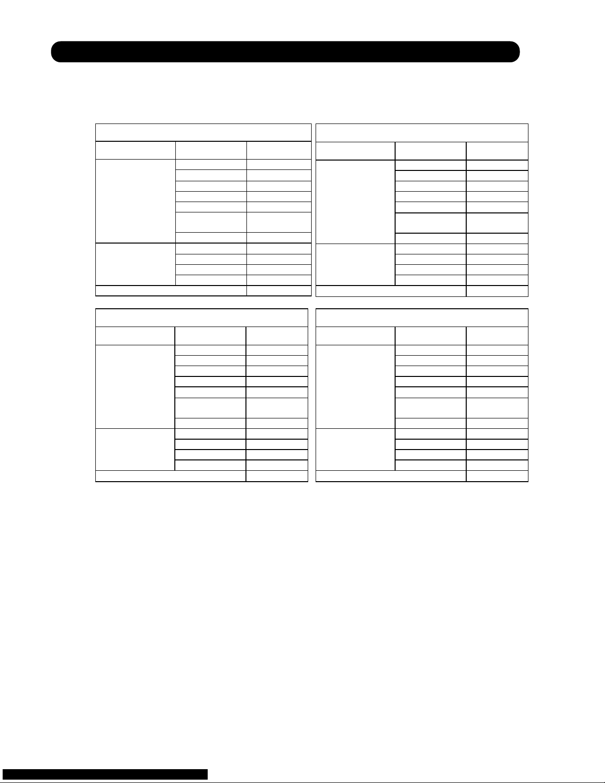
1 . SPECIFICATIONS
R410A
WALL MOUNTED type
INVERTER
Page 5

SPECIFICATIONS
01-01
MODEL NAME
POWER SOURCE
PHASE
FREQUENCY
VOLTAGE
Ph
Hz
V
COOLING
PERFORMANCE
kW
Btu /h
CAPACITY (230V)
W
POWER CONSUMPTION (230V)
EER
W /W
Btu /(h.W)
SEER
RUNNING CURRENT
POWER FACTOR
MAXIMUM CURRENT
MOISTURE REMOVAL
OPERATING NOISE
(SOUND PRESSURE)
Btu /(h.W)
A
%
A
L /hr
Pt /h
dB
dB
dB
dB
dB
INDOOR UNIT
OUTDOOR UNIT
HI
ME
LO
QUIET
kW
Btu /h
CAPACITY
W
POWER CONSUMPTION
COP
W /W
Btu /(h.W)
Btu /(h.W)
HSPF
RUNNING CURRENT
POWER FACTOR
MAXIMUM CURRENT
A
%
A
OPERATING NOISE
(SOUND PRESSURE)
dB
dB
dB
dB
dB
INDOOR UNIT
OUTDOOR UNIT
HI
ME
LO
QUIET
COMPRESSOR
TYPE
OUTPUT
AIR CIRCULATION
(FAN MODE)
INDOOR UNIT
OUTDOOR UNIT
-
W
m3 /h
cfm
m3 /h
cfm
STARTING CURRENT
MINIMUM CIRCUIT AMPACITY
MAXIMUM OVERCURRENT PROTECTION
DESIGN PRESSURE
HIGH SIDE
LOW SIDE
PERMISSIBLE OUTDOOR
TEMPERATURE
COOLING
HEATING
A
A
A
PSI(MPa)
PSI(MPa)
°F
°C
°F
°C
HEATING
PERFORMANCE
OTHER
INDICATION
ASU9RLQ
AOU9RLQ
ASU12RLQ
AOU12RLQ
ASU18CL
AOU18CL
ASU18RL
AOU18RL
1
60
208-230
2.64
(1.05~3.51)
9,000
(3,600~12,000)
670
(200~1,200)
3.93
13.4
21.00
3.2
90
6.0
1.3
2.7
39
34
29
20
47
3.51
(0.87~5.28)
12,000
(3,000~18,000)
830
(200~1,800)
4.25
14.5
11.00
3.9
92
8.5
40
35
28
21
47
Rotary
750
560
329
2,060
1,211
3.9
10
20
450(3.10)
240(1.65)
14~115
-10~46
5~75
-15~24
1
60
208-230
3.51
(1.11~4.26)
12,000
(3,800~14,500)
960
(200~1,500)
3.66
12.5
21.00
4.5
93
7.0
1.8
3.8
41
35
29
20
47
4.68
(0.90~6.18)
16,000
(3,000~21,000)
1,250
(200~2,140)
3.75
12.8
10.55
5.7
95
10.0
41
35
28
21
48
Rotary
750
595
374
1,850
1,088
5.7
12
20
450(3.10)
240(1.65)
14~115
-10~46
5~75
-15~24
1
60
208-230
5.28
(1.62~5.58)
18,000
(5,500~19,000)
1,730
(250~2,000)
3.05
10.4
19.00
7.7
98
9.0
2.8
5.9
44
38
32
25
50
-
-
-
-
-
-
-
-
-
-
-
-
-
-
-
-
-
-
-
Rotary
1,100
700
412
2,000
1,176
7.7
16
20
450(3.10)
240(1.65)
14~115
-10~46
1
60
208-230
5.28
(1.62~5.58)
18,000
(5,500~19,000)
1,730
(250~2,000)
3.05
10.4
19.00
7.7
98
9.0
2.8
5.9
44
38
32
25
50
6.30
(1.32~8.52)
21,600
(4,600~29,000)
1,930
(250~2,930)
3.28
11.2
10.00
8.6
98
13.5
42
37
32
27
50
Rotary
1,100
700
412
2,000
1,176
8.6
16
20
450(3.10)
240(1.65)
14~115
-10~46
5~75
-15~24
Page 6

SPECIFICATIONS
01-02
MODEL NAME
CONNECTING METHOD
PIPE SIZE
LIQUID SIDE
GAS SIDE
INSTALLATION
STANDARD PIPE LENGTH
MAXIMUM PIPE LENGTH
CHARGE LESS PIPE LENGTH
AMOUNT OF ADDITIONAL CHARGE
MAXIMUM HEIGHT DIFFERENCE
NUMBER OF WIRE
NET
DRAIN HOSE LENGTH
GROSS
(PACKAGING WEIGHT)
HEIGHT
HEIGHT
WIDTH
DEPTH
WIDTH
DEPTH
MAIN UNIT
DIMENSIONS
INDOOR UNIT
OUTDOOR UNIT
INDOOR UNIT
OUTDOOR UNIT
INDOOR UNIT
OUTDOOR UNIT
KIND OF REFRIGERANT
AMOUNT OF CHARGING
WEIGHT
OTHER
INDICATION
ASU9RLQ
AOU9RLQ
ASU12RLQ
AOU12RLQ
ASU18CL
AOU18CL
ASU18RL
AOU18RL
Flare
6.35
1/4
9.52
3/8"
7.5
25
20
66
15
49
20
3 /16
15
49
4
580
22-13/16"
9.5
21
35
77
12
26
39
86
283
11-1/8"
790
31-1/8"
230
9-1/16"
540
21-1/4"
790
31-1/8"
290
11-7/16"
316
12-7/16"
835
32-7/8"
360
14-3/16"
625
24-5/8"
919
36-3/16"
385
15-3/16"
R410A
0.95
2-2/16
HEIGHT
HEIGHT
WIDTH
DEPTH
WIDTH
DEPTH
PACKAGE
DIMENSIONS
INDOOR UNIT
OUTDOOR UNIT
-
mm
in.
mm
m
m
m
ft.
g /m
oz. /ft.
m
ft.
-
mm
in.
kg
lbs.
kg
lbs.
kg
kg
mm
-
lbs.
kg
in.
ft.
ft.
lbs.
lbs.
in.
mm
in.
mm
in.
mm
in.
mm
in.
mm
in.
mm
in.
mm
in.
mm
in.
mm
in.
mm
in.
mm
in.
Refrigerant
Flare
6.35
1/4
9.52
3/8"
7.5
25
20
66
15
49
20
3 /16
15
49
4
580
22-13/16"
9.5
21
37
82
12
26
41
90
283
11-1/8"
790
31-1/8"
230
9-1/16"
540
21-1/4"
790
31-1/8"
290
11-7/16"
316
12-7/16"
835
32-7/8"
360
14-3/16"
625
24-5/8"
919
36-3/16"
385
15-3/16"
R410A
1.05
2-5/16
Flare
6.35
1/4
12.7
1/2"
7.5
25
20
66
15
49
20
3 /16
15
49
4
580
22-13/16"
9
20
40
88
12
26
44
97
275
10-13/16"
790
31-1/8"
215
8-7/16"
578
22-3/4"
790
31-1/8"
300
11-13/16"
290
11-7/16"
835
32-7/8"
345
13-9/16"
648
25-1/2"
910
35-13/16"
380
14-15/16"
R410A
1.15
2-9/16
Flare
6.35
1/4
12.7
1/2"
7.5
25
20
66
15
49
20
3 /16
15
49
4
580
22-13/16"
9
20
40
88
12
26
44
97
275
10-13/16"
790
31-1/8"
215
8-7/16"
578
22-3/4"
790
31-1/8"
300
11-13/16"
290
11-7/16"
835
32-7/8"
345
13-9/16"
648
25-1/2"
910
35-13/16"
380
14-15/16"
R410A
1.15
2-9/16
Page 7

2 . DIMENSIONS
R410A
WALL MOUNTED type
INVERTER
Page 8

DIMENSIONS
ASU12RLQ / AOU12RLQ
Models : ASU9RLQ / AOU9RLQ
(unit : mm)
02-01
INDOOR UNIT
OUTDOOR UNIT
790
5617
540
356
290
230
790
283
288
Page 9

DIMENSIONS
ASU18RL / AOU18RL
Models : ASU18CL / AOU18CL
(unit : mm)
02-02
275
215
790
347
578
48
10
320
508
540
20
300
125
66
790
Page 10

3 . REFRIGERANT SYSTEM DIAGRAM
R410A
WALL MOUNTED type
INVERTER
Page 11

REFRIGERANT SYSTEM DIAGRAM
2-Way
valve
Strainer
Strainer
3-Way
valve
Muffler
Muffler
4-Way valve
Expansion valve
Heat exchanger
( INDOOR )
Heat exchanger
( OUTDOOR )
AOU9RLQ
(2Pass)
AOU12RLQ
(4Pass)
Compressor
Cooling
Heating
ASU12RLQ / AOU12RLQ
Models : ASU9RLQ / AOU9RLQ
03-01
Page 12

REFRIGERANT SYSTEM DIAGRAM
2-Way
valve
Strainer
Strainer
Sub-heat
exchanger
( INDOOR )
3-Way
valve
Muffler
4-Way valve
Expansion valve
Heat exchanger
( INDOOR )
Heat exchanger
( OUTDOOR )
Sub-accumulator
Compressor
Cooling
Heating
ASU18RL/ AOU18RL
Models : ASU18CL / AOU18CL
03-02
Page 13

4 . CIRCUIT DIAGRAM
R410A
WALL MOUNTED type
INVERTER
Page 14

CIRCUIT DIAGRAM
ASU12RLQ AOU12RLQ
Models : ASU9RLQ / AOU9RLQ
04-01
OUTDOOR UNIT
INDOOR UNIT
BLACK
BLACK
BLACK
BLACK
ORANGE
YELLOW
RED
PINK
BLUE
RED
WHITE
YELLOW
WHITE
RED
BLUE
BLUE
RED
YELLOW
WHITE
GREEN / YELLOW
GREEN
RED
BLACK
WHITE
W1
W2W3W4
GRAY
GRAY
WHITE
BLACK
RED
YELLOW
BLUE
WHITE
WHITE
WHITE
WHITE
WHITE
WHITE
WHITE
WHITE
RED
CN201
CN4
CN3
CN10CN2
CN1
CN6CN5
CN7
1
2
3
4
5
6
7
8
9
1
2
3
4
5
6
7
8
9
1
2
3
4
5
6
7
8
9
1
2
3
4
1
2
3
4
5
1
2
3
4
5
1
2
3
4
5
1
2
3
4
5
1
2
3
4
5
1
2
3
4
5
1
2
1
2
1
2
3
4
5
6
1
2
3
6
1
2
3
4
1
2
3
1
2
3
4
5
1
2
3
4
5
1
2
3
4
5
TERMINAL
ROOM TEMPERATURE THERMISTOR
PIPE TEMPERATURE THERMISTOR
FAN MOTOR
STEP MOTOR
SWITCH
BARISTOR
FUSE
3.15A
G1 2 3
F. M.
SW
POWER CIRCUIT
THERMAL FUSE
102
M
CONTROL BOARD
DISPLAY BOARD
AIR CLEAN UNIT
Page 15

CIRCUIT DIAGRAM
ASU18RL / AOU18RL
Models : ASU18CL / AOU18CL
04-02
INDOOR UNIT
OUTDOOR UNIT
RED
WHITE
BLACK
RED
WHITE
BLACK
RED
BLACK
WHITE
YELLOW
BLUE
RED
BROWN
BLUE
ORANGE
YELLOW
WHITE
BLACK
BLACK
WHITE
RED
YELLOW
YELLOW
BLACK
BLACK
BROWN
BROWN
BLACK
BLACK
WHITE
WHITE
RED
BLACK
BLACK
BLACK
BLACK
GREEN
CN71
W10
W11
W7
W9
W8
CN801
W4
W2
W1
W3
CN40
CN30
CN70
1
5
4
3
2
6
1
5
4
3
2
6
1
5
4
3
2
6
1
5
4
3
2
1
3
2
1
3
2
6
1
4
3
2
1
4
3
2
1
3
2
1
3
2
1
3
2
1
3
2
2
2
1
1
5
(N)
4
(L)
3
2
1
FUSE
5A-250V
TO INDOOR UNIT
POWER SUPPLY
G
TERMINAL
FUSE 20A-250V
PIPE TEMP. THERMISTOR
DISCHARGE PIPE TEMP. THERMISTOR
OUTDOOR TEMP. THERMISTOR
REACTOR
FAN MOTOR
COMPRESSOR
EXPANSION VALVE
4-WAY VALVE
4WV
E V
F M
C M
S(S)
C(T)
R(R)
CONTROLLER PCB ASSY
ORANGE
RED
YELLOW
PINK
BLUE
BLACK
BLACK
BLACK
BLACK
YELLOW
BLUE
WHITE
BLACK
RED
RED
WHITE
WHITE
WHITE
WHITE
WHITE
WHITE
GRAY
GRAY
WHITE
BLACK
RED
GREEN /
Y
ELLOW
G
321
1
65432
1
65432
1
543
2
1
543
2
1
543
2
1
543
2
1
543
2
1
65432
1
65432
1
65432
7 7 7
1
2
1
2
132
132
CN1
CN7
CN5 CN6 CN2
CN3
CN10
CN201
W1
W3
W2
THERMAL FUSE
102
TERMINAL
TO OUTDOOR UNIT
VARISTOR
FUSE
3.15A
FAN MOTOR
STEP MOTOR
PIPE TEMPERATURE
THERMISTOR
ROOM TEMPERATURE
THERMISTO
R
SW
POWER CIRCUIT
FM
M
CONTROLLER PCB ASSY
INDICATOR PCB ASSY
Page 16

5 . DESCRIPTION OF EACH
CONTROL OPERATION
R410A
WALL MOUNTED type
INVERTER
Page 17

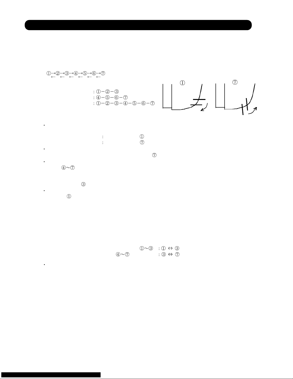
( Fig. 1 : Limit of Maximum Frequency based on Outdoor Temperature )
1. COOLING OPERATION
1-1 COOLING CAPACITY CONTROL
A sensor (room temperature thermistor) built in the indoor unit body will usually perceive
difference or variation between a set temperature and present room temperature, and
controls the operation frequency of the compressor.
* If the room temperature is 4°F(2°C) higher than a set temperature, the compressor operation
frequency will attain to maximum performance.
* If the room temperature is 5°F(2.5°C) lower than a set temperature, the compressor will be
stopped.
* When the room temperature is between +4°F(+2°C) to -5°F(-2.5°C) of the setting temperature,
the compressor frequency is controlled within the range shown in Table1.
However, the maximum frequency is limited in the range shown in Figure 1 based on the
fan speed mode and the outdoor temperature.
minimum
frequency
maximum
frequency
maximum
frequency
ASU9RLQ 18Hz 61Hz 80Hz
ASU12RLQ 18Hz 80Hz 96Hz
ASU18CL 18Hz 70Hz 90Hz
Outside air Outside air
temperature temperature
97°F(36°C)
A zone
93°F(34°C)
90°F(32°C)
B zone
86°F(30°C)
70°F(21°C)
C zone
66°F(19°C)
D zone
Hi Me Lo Quiet
A zone 80Hz 61Hz 51Hz 33Hz
B zone 80Hz 61Hz 51Hz 33Hz
C zone 80Hz 61Hz 51Hz 33Hz
9RLQ
D zone 51Hz 42Hz 36Hz 27Hz
E zone 51Hz 42Hz 36Hz 27Hz
F zone 51Hz 42Hz 36Hz 27Hz
A zone 96Hz 61Hz 51Hz 33Hz12RLQ
B zone 96Hz 61Hz 51Hz 33Hz
C zone 96Hz 61Hz 51Hz 33Hz
D zone 57Hz 42Hz 36Hz 27Hz
E zone 57Hz 42Hz 36Hz 27Hz
18CL
F zone 57Hz 42Hz 36Hz 27Hz
A zone
B zone
C zone
D zone
E zone
F zone
( Table 1 : Compressor Frequency Range )
When the compressor operates for 30 minutes continuously at over the maximum frequency ,
the maximum frequency is changed from Maximum Frequency to Maximum Frequency .
The room temperature is controlled 2°F(1°C) lower than the setting temperature for 40 minutes
after starting the operation.
After 40 minutes, it is controlled based on the normal setting temperature.
05-01
E zone
F zone
50°F(10°C)
32°F(0°C)
54°F(12°C)
36°F(2°C)
90Hz 45Hz 42Hz 30Hz
90Hz 45Hz 42Hz 30Hz
90Hz 45Hz 42Hz 30Hz
58Hz 38Hz 34Hz 24Hz
58Hz 38Hz 34Hz 24Hz
58Hz 38Hz 34Hz 24Hz
ASU18RL 18Hz 70Hz 90Hz
18RL A zone
B zone
C zone
D zone
E zone
F zone
90Hz 45Hz 42Hz 30Hz
90Hz 45Hz 42Hz 30Hz
90Hz 45Hz 42Hz 30Hz
58Hz 38Hz 34Hz 24Hz
58Hz 38Hz 34Hz 24Hz
58Hz 38Hz 34Hz 24Hz
Page 18

2. HEATING OPERATION
2-1 HEATING CAPACITY CONTROL
A sensor (room temperature thermistor) built in the indoor unit body will usually perceive
difference or variation between a set temperature and present room temperature, and
controls the operation frequency of the compressor.
* If the room temperature is lower by 6°F(3°C) than a set temperature, the compressor operation
frequency will attain to maximum performance.
* If the room temperature is higher 5°F(2.5°C) than a set temperatire, the compressor will be
stopped.
minimum
frequency
maximum
frequency
ASU9RLQ 18Hz 130Hz
ASU12RLQ 18Hz 130Hz
ASU18CL
Outside air Outside air
temperature temperature
66°F(19°C)
C zone
63°F(17°C)
57°F(14°C)
B zone
54°F(12°C)
A zone
Hi Me Lo Quiet
A zone 130Hz 96Hz 80Hz 68Hz
B zone 130Hz 96Hz 80Hz 54Hz
9RLQ
C zone 130Hz 96Hz 80Hz 45Hz
A zone 130Hz 96Hz 80Hz 68Hz
B zone 130Hz 96Hz 80Hz 54Hz
12RLQ
C zone 130Hz 96Hz 80Hz 45Hz
A zone - - - B zone - - - -
18CL
C zone - - - -
* When the room temperature is between +4°F(+2°C) to -6°F(-3°C) of the setting temperature,
the compressor frequency is controlled within the range shown in Table2.
However, the maximum frequency is limited in the range shown in Figure 2 based on the
fan speed mode and the outdoor temperature.
( Table 2 : Compressor Frequency Range )
( Fig.2 : Limit of Maximum Frequency based on Outdoor Temperature )
* The room temperature is controlled 4°F(2°C) higher than the setting temperature for 60 minutes
after starting the operation.
After 60 minutes, it is controlled based on the normal setting temperature.
05-02
- -
ASU18RL 18Hz 119Hz
A zone 119Hz 90Hz 70Hz 58Hz
B zone 119Hz 90Hz 70Hz 58Hz
18RL
C zone 119Hz 90Hz 70Hz 58Hz
Page 19

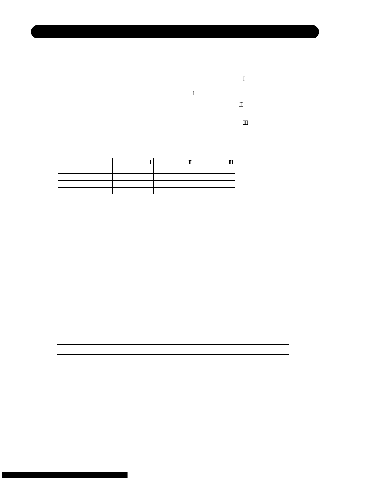
3. DRY OPERATION
3-1 INDOOR UNIT CONTROL
The compressor rotation frequency shall change according to the temperature, set temperature,
and room temperature variation which the room temperature sensor of the indoor unit body has
detected as shown in the Table 3. However, after the compressor is driven, the indoor unit shall
run at operation frequency of 58Hz, for a minute.
Operating
frequency
ASU9RLQ 33Hz
ASU12RLQ 33Hz
ASU18CL 24Hz
room room
temperature temperature
compressor ON
Ts+3°F(1.5°C)
Ts+1°F(0.5°C)
compressor OFF
Compressor
ON
OFF
Indoor fan
Dry air flow
S-Lo
OFF
( Table 3 : Compressor frequency )
( Fig.3 : Compressor Control based on Room Temperature )
( Fig.4 : Indoor Fan Control )
05-03
When an IAQ works in 9/12LA models, it operate with S-LO without stopping.
10 30 60 180 60 180 60 10 30
(SEC)
ASU18RL 24Hz
Page 20

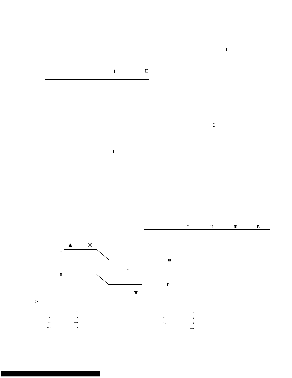
4. AUTO CHANGEOVER OPERATION
When the air conditioner is set to the AUTO mode by remote cintrol, operation starts in the optimum
mode from amoung the HEATING, COOLING, DRY and MONITORING modes. During operation, the
optimum mode is automatically swiched in accordance with temperature changes. The temperature
can be set between 64°F(18°C) and 88°F(30°C) in 2°F(1°C) steps.
.When operation starts, only the indoor and outdoor fans are operated for 1 minute. After 1 minute,
the room temperature and outside air temperature are sensed and the operation mode is
selected in accordance with the table below.
C zone
90°F(32°C)
B zone
14°F(-10°C)
A zone
( Table.4 Operation mode selection table)
Outside air temperature (TO)
Room temperature(TB)
A zone B zone C zone
TB > TS+4°F(2°C)
Monitoring
Cooling
(automatic dry)
Cooling
(automatic dry)
TS+4°F(2°C) TB TS - 4°F(2°C)
Monitoring Monitoring Monitoring
TB TS- 4°F(2°C) *Heating *Heating
*18CL is Monitoring
Monitoring
.When COOING was selected at , the air conditioner operates as follow:
The same operation as COOLING OPERATION of item 1 above is performed.
When the room temperature has remained at (set tempareure -2°F(1°C)) for 8 minutes, operation is
automatically switched to DRY and the same operation as DRY OPERATION of item 3 above
is performed.
If the room temperature reaches (set temperature+4°F(2°C) during DRY operation, operation returns to
COOLING operation.
.When HEATING was selected at , the same operation as HEATING OPERATION of item 2
above is performed.
When the compressor was stopped for 6 consecutive minutes by the temperature control function
after the COOLING or HEATING operation mode was selected at above, operation is switched
to MONITORING and the operation mode is selected again.
1
<
1
2
3
1
4
1
( Fig.5 : Outside air temperature zone selection )
05-04
Page 21
5. INDOOR FAN CONTROL
(1).Fan speed
( Table 5 : Indoor Fan Speed )
ASU9RLQ
Operat ion mode Air flow mode Speed (rpm)
Hi 1390
Me+ 1350
Me 1200
Lo 1000
Quiet 760
Cool air
prevention
760
Heating
S-Lo 480
Hi 1300
Me 1120
Lo 950
Cooling
Fan
Quiet 700
Dry 700
(2).FAN OPERATION
The airflow can be switched in 5 steps such as AUTO, QUIET, LOW, MED, HIGH, while the indoor
fan only runs.
When Fan mode is set at (Auto), it operates on (MED) Fan Speed.
ASU12RLQ
Operation mode Air flow mode Speed (rpm)
Hi 1440
Me+ 1350
Me 1200
Lo 1000
Quiet 760
Cool air
prevention
760
Heating
S-Lo 480
Hi 1370
Me 1150
Lo 950
Cooling
Fan
Quiet
700
Dry 700
ASU18CL
Operation mode Air flow mode Speed (rpm)
Hi -
Me+ -
Me -
Lo -
Quiet -
Cool air
prevention
-
Heating
S-Lo 480
Hi 1480
Me 1260
Lo 1040
Cooling
Fan
Quiet
850
Dry 850
05-05
ASU18RL
Operation mode Air flow mode Speed (rpm)
Hi 1480
Me+ 1420
Me 1300
Lo 1110
Quiet 950
Cool air
prevention
850
Heating
S-Lo 480
Hi 1480
Me 1260
Lo 1040
Cooling
Fan
Quiet
850
Dry 850
Page 22

(3).COOLING OPERATION
Switch the airflow [AUTO], and the (Fig.6)
indoor fan motor will run according airflow change - over ( Cooling:AUTO )
to a room temperature, as shown in When the room
Figure 6. temperature rises
On the other hand, if switched in
[HIGH] [QUIET], the indoor motor
+5°F(+2.5°C)
will run at a constant airflow of [COOL]
operation modes QUIET, LOW, MED,
HIGH, as shown in Table 5.
+3°F
(+1.5°C)
+2°F(+1°C)
LOW mode
When the room
temperature lowers
(Room temperature) D (Setting temperature)
(4).DRY OPERATION
(5).HEATING OPERATION
Switch the airflow [AUTO], and the (Fig.7)
indoor fan motor will run according airflow change - over ( Heating:AUTO)
to a room temperature, as shown in When the room
Figure 7. temperature rises
On the other hand, if switched
LOW mode
[HIGH] [QUIET], the indoor motor -2°F(-1°C)
will run at a constant airflow of [HEAT]
-3°F(-1.5°C)
operation modes QUIET, LOW, MED,
HIGH, as shown in Table 5. -4°F(-2°C)
-5°F(-2.5°C)
MED + mode
When the room
temperature lowers
(Room temperature) D (Setting temperature)
(6).COOL AIR PREVENTION CONTROL (Heating mode)
Indoor heat exchanger Indoor heat exchanger
temperature temperature
117°F(47°C)
Hi
104°F(40°C)
Me+
99°F(37°C)
Lo
Cool air prevention
86°F(30°C)
S-Lo
Refer to the table 4.
Durring the dry mode operation, the fan speed
setting can not be changed.
The maximum value of the indoor fan speed is set as shown in Figure 8, based on the detected
temperature by the indoor heat exchanger sensor on heating mode.
(Fig.8 : Cool Air Prevention Control)
05-06
104°F(40°C)
82°F(28°C)
90°F(32°C)
93°F(34°C)
HIGH mode
MED mode
+4°F(+2°C)
MED mode
Page 23

6. OUTDOOR FAN CONTROL
(1). Fan Speed
Cooling Dry Heating
ASU9RLQ 800/760/470
400/280
ASU12RLQ
200
ASU18CL
( Table 6 : Outdoor fan speed )
*
The outdoor fan speed mentioned avobe depends on the compressor frequency.
(When the compressor frequency increases, the outdoor fan speed also changes to the higher
speed. When the compressor frequescy decreases, the outdoor fan speed also changes to the
lower speed.)
*
It runs at 500(A-D ZONE)/200(E,F ZONE) rpm for 20 seconds after starting up the outdoor fan.
*
After the defrost control is operated on the heating mode, the fan speed keeps at the higher speed
as table 7 without relating to the compressor frequency.
05-07
A-D
E
F
A-D
E
F
A-D
E
F
ZONE
800/760/470
400/280
250/200
860/820/670/500
400/340/280
280/250/230
500
400/280
200
500
400/280
250/200
500
400/340/280
280/250/230
760/680/470
760/680/470
-
Refer to Fig1.
(rpm)
ASU18RL A-D
E
F
860/820/670/500
400/340/280
280/250/230
500
400/340/280
280/250/230
820/750/670/450
(1). Fan Speed
*
Outdoor temperature falls, and if it becomes E and F zone(Refer to Fig1), rotations of fan speed
will fall.
( Table 7 : Outdoor fan speed after the defrost )
ASU9RLQ
ASU12RLQ
ASU18CL
ASU18RL
Min
800rpm
900rpm
-
950rpm
Page 24
7. LOUVER CONTROL
(1). VERTICAL LOUVER CONTROL
Each time the button is pressed, the air direction range will change as follow:
Cooling / Dry mode
Heating mode
Fan mode
Use the air direction adjustments within the ranges shown above.
The vertical airflow direction is set automatically as shown, in accordance with the type of operation
selected.
Cooling / Dry mode Horizontal flow
Heating mode Downward flow
When the temperature of the air being blown out is low at the start of heating operation or during
defrosting, the airflow direction temporarily becomes to prevent cold air being blown onto the body.
During use of the Cooling and Dry modes, do not set the Air Flow Direction Louver in the Heating
range ( ) for long period of time, since water vapor many condense near the outlet louvers and
drop of water may drip from the air conditioner. During the Cooling and Dry modes, if the Air Flow
Direction Louvers are left in the hating range for more than 30minutes, they will automatically
return to position .
During Monitor operation in AUTO CHANGEOVER mode, the airflow direction automatically
becomes , and it cannot be adjusted.
Cooling mode / Dry mode / Fan mode( )
Heating mode / Fan mode( )
(Function Range)
(Fig 9: Air Direction Range)
(Operation Range)
(2). SWING OPERATION
When the swing signal is received from the remote controller, the vertical louver starts to
swing.
(Swinging Range)
When the indoor fan is either at S-lo or Stop mode, the swinging operation is interrrupted
and the louver stops at the memorized position.
05-08
Page 25

8. COMPRESSOR CONTROL
(1). OPEARTION FREQUENCY RANGE
The operation frequency of the compressor is different based on the operation mode as
shown in the table 8.
Cooling Heating
Min Max Min Max
Dry
ASU9RLQ 18Hz 80Hz 18Hz 130Hz 33Hz
ASU12RLQ 18Hz 96Hz 18Hz 130Hz 33Hz
ASU18CL 18Hz 90Hz - - 24Hz
ASU9RLQ 56Hz 74Hz 87Hz 97Hz 108Hz 119Hz
ASU12RLQ 56Hz 74Hz 87Hz 97Hz 108Hz 119Hz
ASU18CL 40Hz 59Hz 72Hz 80Hz 101Hz 110Hz
ASU9RLQ 80sec 60sec 60sec 180sec 60sec 60sec
ASU12RLQ 80sec 60sec 60sec 180sec 60sec 60sec
ASU18CL 60sec 40sec 40sec 60sec 150sec 60sec
(Table 8 : Compressor Operation Frequency Range)
(2). OPEARTION FREQUENCY CONTROL AT START UP
The compressor frequency soon after the start-up is controlled as shown in the figure 10.
(Fig.10 : Compressor Control at Start-up)
Time
Time Time Time
Time
Time
(Frequency)
(Time)
Frequency
Frequency
Frequency Frequency
Frequency
Frequency
Time Time
Time Time Time Time
Frequency
Frequency
Frequency
Frequency
Frequency
Frequency
05-09
ASU18RL 18Hz 90Hz 18Hz 119Hz 24Hz
ASU18RL 40Hz 59Hz 72Hz 80Hz 101Hz 110Hz
ASU18RL 60sec 40sec 40sec 60sec 150sec 60sec
Page 26

9. TIMER OPEARTION CONTROL
(1). OPEARTION FREQUENCY RANGE
The table 9 shows the available timer setting based on the product model.
ON TIMER / OFF TIMER PROGRAM TIMER SLEEP TIMER
ASU9RLQ
ASU12RLQ
ASU18CL
OFF timer : When the clock reaches the set time, the air conditioner will be turned off.
Operation mode
Stop mode
Set time of timer
ON timer : When the clock reaches the set time, the air conditioner will be turned on.
Operation mode
Stop mode
Set time of timer
The program timer allows the OFF timer and ON timer to be used in combination one time.
Operation mode
Operation will start from the timer setting (either OFF timer or ON timer) whichever is closest
to the clock's current timer setting. The order of operations is indicated by the arrow in the remote
control unit's display.
SLEEP timer operation cannot be combined with ON timer operation.
(Table 9 : Timer Setting)
(2). PROGRAM TIMER
Stop mode
Stop mode
Stop mode
Operation mode
Operation mode
Set time
Set time Set time Set time
05-10
ASU18RL
Page 27

(3). SLEEP TIMER
If the sleep is set, the room temperature is monitored and the operation is stopped automatically.
If the operation mode or the set temperature is change after the sleep timer is set, the operation is
continued according to the changed setting of the sleep timer from that time ON.
Set temperature rises
( Ts : Set temperature )
Stop of operation
Set temperature lowers
( Ts : Set temperature )
Ts
Stop of operation
In the cooling operation mode
When the sleep timer is set, the setting temperature is increased 2°F(1°C).
It increases the setting temperature another 2°F(1°C) after 1 hour.
After that, the setting temperature is not changed and the operation is stopped at the time
of timer setting.
Ts
+2°F(+1°C)
+4°F(+2°C)
Set
60min
In the heating operation mode
When the sleep timer is set, the setting temperature is decreased 2°F(1°C).
It decreases the setting temperature another 2°F(1°C) every 30 minutes.
Upon lowering 8°F(4°C), the setting temperature is not changed and the operation stops at
the time of timer setting.
-8°F(-4°C)
-6°F(-3°C)
-4°F(-2°C)
-2°F(-1°C)
Set
30min
30min
30min
05-11
Page 28

10. ELECTRONIC EXPANSION VALVE CONTROL
The most proper opening of the electronic expansion valve is calculated and controlled under the
present operating condition based on the following values.
The compressor frequency, the temperatures detected by the discharge temperature sensor, the
indoor heat exchanger sensor, the outdoor heat exchanger sensor, and the outdoor temperature
sensor.
The pulse range of the electronic expansion valve control is between 60 to 480 pulses.
The expansion valve is set at 480 pulses after 110 seconds of stopping compressor.
At the time of supplying the power to the outdoor unit, the initialization of the electronic
expansion valve is operated (528 pulses are input to the closing direction).
11. TEST OPERATION CONTROL
Under the condition where the air conditioner runs, press the test operation button of the remote
control, and the test operation control mode will appear. During test running, the operation lamp
and timer lamp of the air conditioner body twinkle simultaneously. Set the test operation mode,
and the compressor will continue to run regardless of whether the room temperature sensor detects.
The compressor won't enter operation status for 2 minutes and 20 seconds after the compressor is
stopped, even if any operation is given.
At the time when the air conditioner is switched from the cooling mode to heating mode, the
compressor is stopped, and the four-way valve is switched in 2 minutes and 20 seconds later after
the compressor stopped.
When the power was interrupted by a power failure, etc. during operation, the operation contents
at that time are memorized and when power is recovered, operation is automatically started with
the memorized operation contents.
When the power is interrupted and recovered during timer operation, since the timer operation time
is shifted by the time the power was interrupted, an alarm is given by blinking (7 sec ON/2 sec OFF)
the indoor unit body timer lamp.
[Operation contents memorized when the power is interrupted]
Operation mode
Set temperature
Set air flow
Timer mode and timer time
Set air flow Direction
Swing
The test operation mode is released if 60 minutes have passed after setting up the test operation.
12. PREVENT TO RESTART FOR 3 MINUTES ( 3 MINUTES ST )
13. FOUR-WAY VALVE EXTENSION SELECT
14. AUTO RESTART
05-12
Air clean(Only 9/12LA model)
Page 29

15. MANUAL AUTO OPERATION (Indoor unit body operation)
If MANUAL AUTO Button is set, the operation is controlled as shown in Table 10.
If the remote control is lost or battery power dissipated, this function will work without the remote
control.
OPERATION MODE Auto changeover
FAN CONT. MODE Auto
TIMER MODE Continuous
SETTING TEMP. 75°F(24°C)
SETTING LOUVER Standard
SWING OFF
When the outdoor heat exchanger temperature is lower than temperature and the heating operation has
been stopped for 30 minutes, power is applied to the compressor and the compressor is heated.
(By heating the compressor, warm air is quickly discharged when operation is started.)
When operation was started, and when the outdoor temperature rises to temperature or greater, preheating
is ended.
ASU9RLQ
ASU12RLQ
ASU18CL
ASU9RLQ
900rpm 36Hz
ASU12RLQ
900rpm 36Hz
(Table 10)
(No timer setting available)
17. COMPRESSOR PREHEATING
(Table 11 : Preheating Operation / Release Temperature)
Temperature
Temperature
41°F(5°C)
41°F(5°C)
-
45°F(7°C)
45°F(7°C)
-
18. COIL DRY OR AIR CLEAN OPERATION CONTROL
The coil-dry operation functions by pressing COIL DRY button on the remote controller.
The coil-dry operation is consisted of 3 cycles of [Fan operation 3 minutes / Heating operation
2 minutes], and Fan operates for 3 minutes at last before ending the air conditioner operation.
(It takes 18 minutes to complete the coil-dry operation.)
(Table 12 : COIL-DRY or AIR-CLEAN Operating Functions)
Indoor Fan Speed
Compressor
Frequency
Louver
Position
Main Unit
Indication
COIL-DRY or AIR-CLEAN indication : ON
Other indication : OFF
05-13
Forced cooling operation
Cooling
16. FORCED COOLING OPERATION
Forced cooling operatio is started when pressing MANUAL AUTO button for 10 seconds or more.
During the forced cooling operation, it operates regardless of room temperature sensor.
Operation LED and timer LED blink during the forced cooling operation. They blink for 1 second ON
and 1 second OFF on both operation LED and timer LED (same as test operation).
Forced cooling operation is released after 60 minutes of starting operation.
The FORCED COOLING OPERATION will start as shown in Table10.
-
480rpm
ASU18RL
41°F(5°C)
45°F(7°C)
ASU18RL
900rpm 34Hz
480rpm
(1). COIL DRY OPERATION CONTROL (ASU18RL model only)
(2). AIR CLEAN OPERATION CONTROL (ASU9/12RLQ model only)
The coil-dry operation functions by pressing AIR CLEAN button on the remote controller.
It continues from COIL DRY operation, it turns on electricity to AIR CLEAN UNIT, sterilization is
performed for 15 minutes.
Indoor unit fan motor operation under AIR CLEAN operation : The cycle of 480rpm Fixation
5 sec ON /1 min OFF is repeated.
(It takes 33 minutes to complete the AIR CLEANING operation.)
Hi
Horizontal
OFF
Room Temp is not controlled
Manual auto operation
-
Page 30

19. DEFROST OPERATION CONTROL
(1). CONDITION OF STARTING THE DEFROST OPERATION
The defrost operation starts when the outdoor heat exchanger temperature sensor detects
the temperature lower than the values shown in Table 13.
(Table 13 : Condition of starting Defrost Operation)
ASU9RLQ
ASU12RLQ
ASU18CL
ASU18RL
ASU9RLQ
ASU12RLQ
ASU18RL
1 time defrosting
after starting
operation
ST
Compressor operating time
Less than 20 minutes 20 to 60 minutes
60 minutes to 4 hours
After 4 hours
Does not operate
- 16°F(-9°C)
- 16°F(-9°C)
-
- 16°F(-9°C)
- 23°F(-5°C)
- 23°F(-5°C)
-
- 23°F(-5°C)
- 27°F(-3°C)
-
- 27°F(-3°C)
- 27°F(-3°C)
ASU9RLQ
ASU12RLQ
ASU18CL
ASU18RL
Defrosting after 2
time upon starting
operation
nd
Less than 35 minutes
35 minutes to
4 hours
Does not operate
Compressor operating time
After 4 hours
- 27°F(-3°C)
- 27°F(-3°C)
-
- 27°F(-3°C)
- 21°F(-6°C)
- 21°F(-6°C)
-
- 21°F(-6°C)
(2). CONDITION OF THE DEFROST OPERATION COMPLETION
Defrost operation is released when the conditions become as shown in Table 14.
(Table 14 : Defrost Release Condition)
Release Condition
Outdoor heat exchanger temperature sensor value is higher than 61°F(16°C) or
Compressor operation time has passed 15 minutes.
Outdoor heat exchanger temperature sensor value is higher than 61°F(16°C) or
Compressor operation time has passed 15 minutes.
Outdoor heat exchanger temperature sensor value is higher than 50°F(10°C) or
Compressor operation time has passed 15 minutes.
05-14
Page 31

Defrost Flow Chart
The defrosting shall proceed by the integrating operation time and outdoor heat exchanger
temperature as follows.
(Not defrosted for 10 minutes)
(In case of 1st defrost) (In case of 2nd and later defrost)
Compressor OFF
Outdoor fan motor OFF
30 sec later four - way valve OFF
36 sec later compressor ON
Heating operation start : Compressor ON
Compressor integrating
operation:
Over 20 minutes to
below 60 minutes
Compressor integrating
operation:
Over 60 minutes to
below 240 minutes
Compressor integrating
operation:
Over 240 minutes
Compressor integrating
operation:
Over 35 minutes to
below 240 minutes
Compressor integrating
operation:
Over 240 minutes
Outdoor heat exchanger
temperature:
Below - 16°F(-9°C)
Outdoor heat exchanger
temperature:
Outdoor heat exchanger
temperature:
Outdoor heat exchanger
temperature:
Outdoor heat exchanger
temperature:
Defrost start
Defrost Indicator:
[Operation lamp]
7 sec ON / 2 sec OFF
Outdoor heat exchanger temperature:
Over 50°F(10°C) / 61°F(16°C)
or
Compressor ON time:
Over 15 minutes
Defrost end
Below - 23°F(-5°C)
Below - 27°F(-3°C)
Below - 21°F(-6°C)
Below - 27°F(-3°C)
05-15
Page 32

20. OFF DEFROST OPEARTION CONTROL
(1). OFF DEFROST OPERATION CONDITION
When operation stops in the [Heating operation] mode, if frost is adhered to the outdoor unit heat
exchanger, the defrost operation will proceed automatically. In this time, if indoor unit operation
lamp flashes slowly (7 sec ON / 2 sec OFF), the outdoor unit will allow the heat exchanger to defrost,
and then stop.
In heating operation, the outdoor heat exchanger temperature is less than - 25°F(-4°C), and
compressor operation integrating time lasts for more than 30 minutes.
ASU9RLQ
ASU12RLQ
ASU18RL
OFF Defrost Flow Chart
Heating operation stop
Outdoor heat exchanger temperature:
Below - 25°F(-4°C)
and
Compressor integrating operation:
Over 30 minutes
Defrost start
Defrost Indicater:
[Operation lamp]
Outdoor heat exchanger temperature:
Over 50°F(10°C) / 61°F(16°C)
or
Compressor ON time:
Over 15 minutes
Defrost end
(2). OFF DEFROST END CONDITION
Release Condition
Outdoor heat exchanger temperature sensor value is higher than 61°F(16°C) or
Compressor operation time has passed 15 minutes.
Outdoor heat exchanger temperature sensor value is higher than 61°F(16°C) or
Compressor operation time has passed 15 minutes.
Outdoor heat exchanger temperature sensor value is higher than 50°F(10°C) or
Compressor operation time has passed 15 minutes.
7 sec ON / 2 sec OFF
05-16
Page 33
21. VARIOUS PROTECTIONS
(1). DISCHARGE GAS TEMPERATURE OVERRISE PREVENSION CONTROL
The discharge gas thermosensor (discharge thermistor : Outdoor side) will detect discharge gas
temperature.
ASU9RLQ 219°F(104°C) 214°F(101°C) 230°F(110°C)
ASU12RLQ 219°F(104°C) 214°F(101°C) 230°F(110°C)
ASU18CL 219°F(104°C) 214°F(101°C) 230°F(110°C)
ASU18RL 219°F(104°C) 214°F(101°C) 230°F(110°C)
ASU9RLQ ASU12RLQ ASU18CL ASU18RL
OT (Control / Release)
63°F(17°C)
54°F(12°C)
ASU9RLQ ASU12RLQ ASU18CL ASU18RL
115°F(46°C)
104°F(40°C)
3.5A / 3.0A
4.0A / 3.5A
5.5A / 5.0A
4.0A / 3.5A
5.0A / 4.5A
6.5A / 6.0A
4.5A / 4.0A
6.0A / 5.5A
8.5A / 8.0A
4.5A / 4.0A
6.0A / 5.5A
8.5A / 8.0A
6.5A / 6.0A
8.0A / 7.5A
8.0A / 7.5A
8.0A / 7.5A
6.5A / 6.0A
8.0A / 7.5A
8.5A / 8.0A
9.5A / 9.0A
/
/
/
/
When the discharge temperature becomes higher than Temperature ,the compressor frequency
is decreased 20 Hz, and it continues to decrease the frequency for 20 Hz every 120 seconds until
the temperature becomes lower than Temperature .
When the discharge temperature becomes lower than Temperature ,the control of the control of the
compressor frequency is released.
When the discharge temperature becomes higher than Temperature ,the compressor is stopped
and the indoor unit LED starts blinking.
(Table 15 : Discharge Temperature Over Rise Prevension Control / Release Temperature)
Temperature
Temperature
Temperature
(2). CURRENT RELEASE CONTROL
The compressor frequency is controlled so that the outdoor unit input current does not exceeds
the current limit velue that was set up with the outdoor temperature.
The compressor frequency returns to the designated frequency of the indoor unit at the time
when the frequency becomes lower than the release value.
(Table 16 : Current Release Operation Value / Release Value)
[ Heating ]
[ Cooling / Dry ]
OT : Outdoor Temperature
OT : Outdoor Temperature
OT (Control / Release)
41°F(5°C)
05-17
7.0A / 6.5A
9.0A / 8.5A
10.5A / 10.0A
12.0A / 11.5A
OT (Control / Release)
63°F(17°C)
54°F(12°C)
41°F(5°C)
OT (Control / Release)
63°F(17°C)
54°F(12°C)
41°F(5°C)
OT (Control / Release)
63°F(17°C)
54°F(12°C)
41°F(5°C)
115°F(46°C)
104°F(40°C)
OT (Control / Release)
115°F(46°C)
104°F(40°C)
OT (Control / Release)
115°F(46°C)
104°F(40°C)
OT (Control / Release)
Page 34
(3). ANTIFREEZING CONTROL (Cooling and Dry mode)
The compressor frequency is decrease on cooling & dry mode when the indoor heat exchanger
temperature sensor detects the temperature lower than Temperature .
Then, the anti-freezing control is released when it becomes higher than Temperature .
A-D
E,F
(Table 17 : Anti-freezing Protection Operation / Release Temperature)
TemperatureTemperature
39°F(4°C)
39°F(4°C)
45°F(7°C)
55°F(13°C)
(4). COOLING PRESSURE OVERRISE PROTECTION
(Table 18 : Cooling Pressure Over Rise Protection Function Temperature)
When the outdoor unit heat exchange sensor temperature rises to temperature or greater, the
compressor is stopped and trouble display is performed.
ASU9RLQ 153°F(67°C)
ASU12RLQ 153°F(67°C)
ASU18CL 153°F(67°C)
ASU18RL 153°F(67°C)
Temperature
(5). HIGH TEMPERATURE RELEASE CONTROL ( HEATING MODE )
On heating mode, the compressor frequency is controlled as following based on the
detection value of the indoor heat exchanger temperature sensor.
05-18
[ ASU9/12RLQ ]
[ ASU18RL ]
46Hz or greater 45Hz
39Hz or greater 38Hz
39 45Hz
38Hz
26 38Hz 25Hz
19 29Hz 18Hz
18 25Hz OFF
OFF
Indoor heat exchange
temperature
[ Control System ]
Temperature
Temperature
Refer to below
Temperature
Temperature
The compressor frequency is
precisely controlled so that
it does not exceeds Temperature .
It returns to the normal operation
Compressor Operation
18Hz
30
Frequency down every 120 seconds
Frequency down every 120 seconds
ASU9RLQ 131°F(55°C)
ASU12RLQ 131°F(55°C)
ASU18CL ASU18RL 131°F(55°C)
Temp
Temp Temp Temp
127°F(53°C)
127°F(53°C)
-
127°F(53°C)
126°F(52°C)
126°F(52°C)
-
126°F(52°C)
122°F(50°C)
122°F(50°C)
-
122°F(50°C)
Page 35

6 . REFRIGERANT CAUTION -R410A-
R410A
WALL MOUNTED type
INVERTER
Page 36
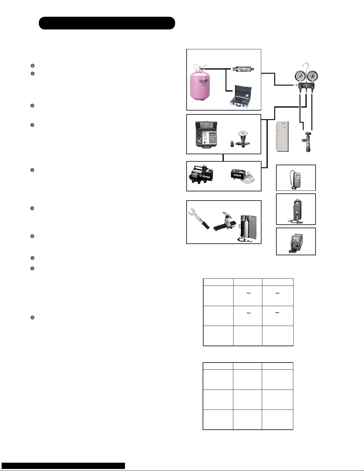
1. R410A TOOLS
Gauge manifold . . . . . . . . . . . . . . . . . . . . . (Fig.4-1)
Since the normal pressure is high, the connection pipe size
is also different.
Charge hose . . . . . . . . . . . . . . . . . . . . . . . (Fig.4-2)
Refrigerant cylinder . . . . . . . . . . . . . . . . . (Fig.4-3)
Confirm the refrigerant type before charging. Always
charge liquid-phase refrigerant.
Electronic balance for refrigerant
charging . . . . . . . . . . . . . . . . . . . . . . . . . . . (Fig.4-4)
Electronic balance is recommended as in the case of
R410A.
Vacuum pump with adapter to prevent
reverse flow . . . . . . . . . . . . . . . . . . . . . . . .(Fig.4-5)
Conventional pump can be used.
Vacuum holder . . . . . . . . . . . . . . . . . . . . . (Fig.4-6)
Conventional pump can be used if adapter for preventing
vacuum pump oil from flowing back is used.
Gas leakage tester . . . . . . . . . . . . . . . . . . (Fig.4-7)
Exclusive for HFC
Refrigerant cleaner . . . . . . . . . . . . . . . . . . (Fig.4-8)
Brown paint as designated by the ARI, USA
Flare tool . . . . . . . . . . . . . . . . . . . . . . . . . . (Fig.4-9)
Torque wrench . . . . . . . . . . . . . . . . . . . . (Fig.4-10)
Refrigerant recovering
equipment (Collector) . . . . . . . . . . . . . . (Fig.4-11)
The type which can be used for any refrigerant is available
Nitrogen cylinder . . . . . . . . . . . . . . . . . . . (Fig.4-12)
This prevents an oxide film from forming in the pipe silveralloy brazing work by turning the air out of the pipe and
preventing the inside combustion.
Safety charger . . . . . . . . . . . . . . . . . . . . . (Fig.4-13)
It is always compulsory to change the liquid, because
R410A is a mixed refrigerant and there is some fear that a
mixing ratio changes. In order to avoid the refrigerant from
returning to the compressor in a liquid state, the refrigerant
can be charged instead of giving a load to the compressor
with a safety charger.
Control valve . . . . . . . . . . . . . . . . . . . . . . (Fig.4-14)
The control valve prevents the refrigerant from spouting
when it is removed, as the charging hose side and the service port side are possible to open and close at the same
time.
Thermistor vacuum gauge . . . . . . . . . . . (Fig.4-15)
To remove moisture from the refrigerating cycle completely, it is necessary to perform appropriate vacuum drying.
For that reason, vacuum conditions can be confirmed certainly.
Vacuum valve . . . . . . . . . . . . . . . . . . . . . (Fig.4-16)
This valve builts in a check valve, and it is easily possible
to vacuum a refrigerating cycle or check for degree of vacuum with it.
TOOLS AND EQUIPMENT (R410A)
Gauge Manifold
R410A
R22, R407C
High
pressure
gauge
Compond
gauge
Port size
-0.1 5.3
Mpa
-0.1 3.8
Mpa
1/2UNF
5/16"
-0.1 3.5
Mpa
-0.1 1.7
Mpa
7/16UNF
1/4"
*
1
Charge hose
R410A
R22, R407C
Normal
pressure
Port size
5.1 Mpa
27.4 Mpa
1/2UNF
3.4 Mpa
17.2 Mpa
7/16UNF
*
2
Breaking
pressure
This air conditioner used R410A.
For installation and servicing, it is necessary to prepare the
tools and machines that are diff
erent from the previous
refrigerant.
Mark shows the exclusive use for R410A.
The specification of the gauge is different due
to higher pressure.
The size of connection pipe is also different to
prevent mis-use.
The shape of flare is different for
high pressure condition.
06-01
Gas charging
Vacuuming
Piping work
Pressure control and
Circuit switching
Charge hose
Fig.4-2
Outdoor unit
Electronic charging
scale Fig.4-4
Vacuum pump Fig.4-5
Thermistor vacuum gauge Fig.4-15
Vacuum
Valve Fig.4-16
Safety charger Fig.4-13
Control Valve
Fig.4-14
Vacuum holder Fig.4-6
Leakage tester Fig.4-7
Cleaner Fig.4-8
Collector Fig.4-11
Nitrogen Cylinder
Fig.4-12
Torque wrench
Fig.4-10
Flare tool
Fig.4-9
Gauge manifold
Fig.4-1
Fig.4-3
Refrigerant cylinder
Vacuum control
Low pressure
High pressure
side
side
Page 37
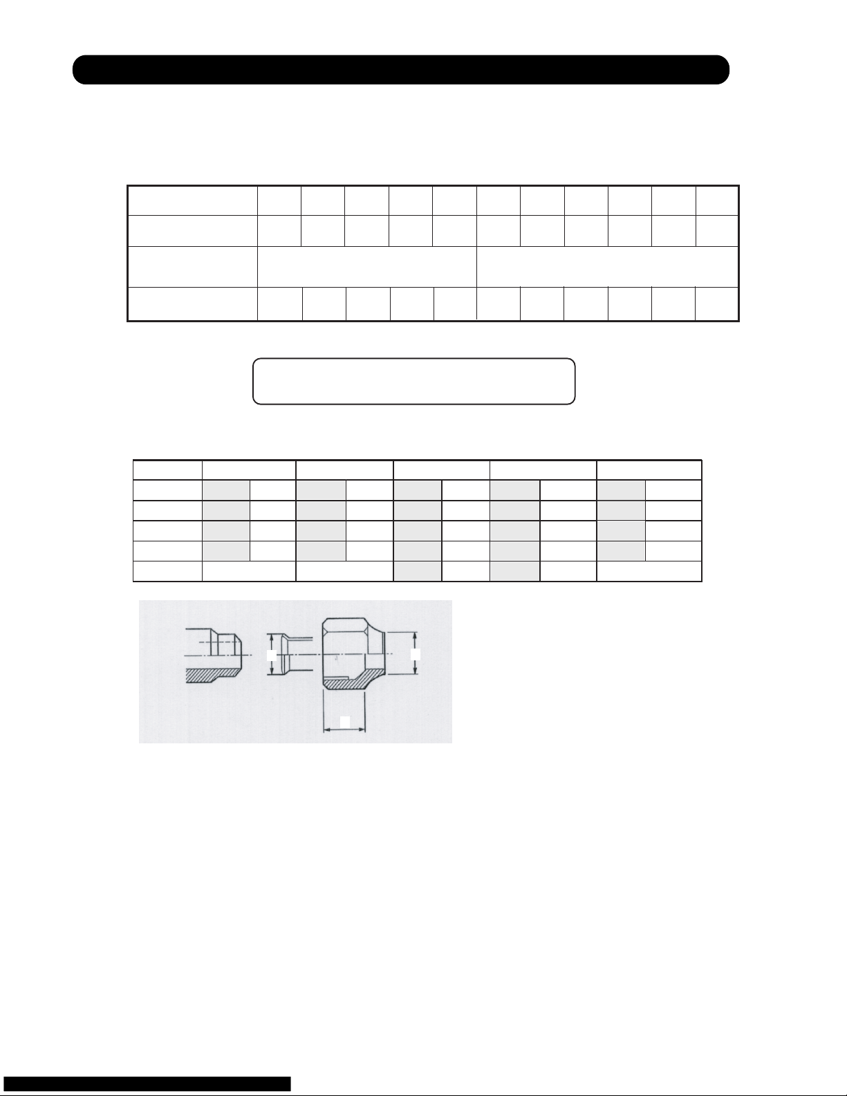
2. PRECAUTION FOR INSTALLATION
06-02
Precaution for installation
The pipe must be properly pressure rated for R410A
The pipe must be an air-conditioning refrigerant pipe.
Flare and flare nuts
Diameter 1/4” (6.35mm) 3/8” (9.52mm) 1/2” (12.7mm)
Refrigerant
R410A
R22
/R407C
R410A R410A
A 9.1 9.0 13.2 13.0 16.6
16.2
B 13 12 20 15 13 20
C 12 11 16 12.5 19 16
Nut width 17 22 26 24
Always use the flare nut that is packed
with the product.
Do not use existing (for R22) pipes
•
Be sure to use new pipes when replacing
conventional (R22) model with HFC
(R407C, R410A) model.
•
If you use existing pipes, it may cause
resolution of compressor oil by remaining
mineral oil.
3/8” (15.88mm)
R410A
22
29
19.7
25
R22
/R407C
R22
/R407C
R22
/R407C
19.4
23
20
27
3/4” (19.05mm)
R410A
24
36
24
29
R22
/R407C
23.7
29
24
Material
Nominal diameter
(in)
1/4" 3/8" 1/2" 5/8" 3/4" 7/8" 1 1/8" 1 1/4" 1 1/2"1 3/8"1"
6.35 9.52 12.70 15.88 19.05 22.22 28.58 31.75 38.1034.9225.40
Outside diameter
(mm)
Wall thickness
(mm)
0.8 0.8 0.8 1.0 1.2 1.0 1.0 1.1 1.31.21.0
1) Allowable tensile stress 33 (N/mm );
>
=
2
2) Allowable tensile stress 61 (N/mm ); 3) Design pressure 4.2MPa.
>
=
2
JIS H3300-C1220T-H or equivalent
2)
COPPER
JIS H3300-C1220T-O or equivalent
1)
COPPER
3)
Pipe diameter, recommended material and wall thickness
A
C
B
Page 38
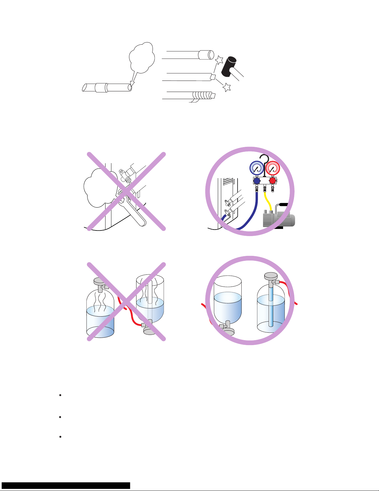
Be careful not to mix moisture and
contamination into the pipe
Moisture and contamination
in the pipe is a cause of
trouble.
Air purge
Always use a
vacuum pump
to purge air.
Refrigerant charge
Do it always from the liquid phase
side.
Don't charge from the gas phase side.
Compressor oil is changed
Be careful to handle synthetic oil, since it
resolves easily by moisture and
contamination.
Don't mix new synthetic oil and mineral oil.
It may cause trouble.
We developed new synthetic oil, since HFC
refrigerant doesn't dissolve in mineral (for R22)oil.
06-03
Page 39

3. PRECAUTION FOR SERVICING
Feature 1 Refrigerant oil is different from before.
Refrigerant oil for
New Refrigerant
Synthetic oil
Ether
Esther
Different point from
previous one
Previously it was
mineral oil.
Absorbent character
is high.
Contamination occurs
when mixed withe other
kind of oil.
Use the gauge manifold and charge hose
for New Refrigerant(HFC), which shall
be segregated from those of R22.
Attach the stop valve on the vacuum pump
and avoid the oil from reverse frow.
It is necessary to use the vacuum pump
which can obtain the high vacuum condition.
Precaution on Tools
Feature 2 New Refrigerant has Approx 1.6 times higher pressure than previous refrigerant.
R410A
High Pressure
Different point from
previous one
Diameter of Service port
has been changed from
1/4 Flare to 5/16 Flare.
It requires the gauge manifold and charge
hose exclusively for R410A.
It requires the flare tool and torque wrench
that satisfies New JIS standard.
Precaution on Tools
R410A R22
1.6 times of R22.
JIS standard of flare
process It became lager
To keep thethickness of
copper tube.
(1/4,3/3=more than 0.8mm)
Previous flare tool + flare adapter can be used as well.
06-04
Page 40
4. NEW REFRIGERANT R410A
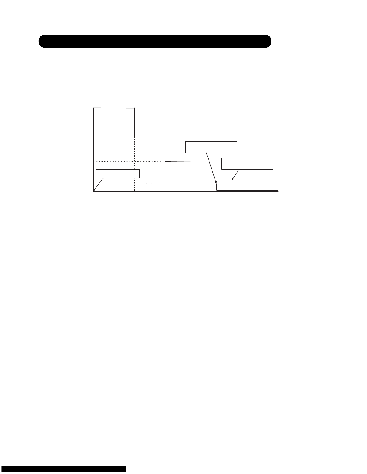
What is HFC ?
Phase-out schedule of HCFC
according to Montreal protocol
1996 20102000 2004 2015 2020 2030
60
40
20
100
(Year)
(%)
80
(HCFC consumption of 1989) +
(CFC consumption of 1989) x 2.8%
65%
35%
10%
0.5%
started control
only service use
total abolition
100% =
0
*
06-05
Page 41

Ozone Layer depleting mechanism
CFC
CFCl
2
Cl Ozone
(O3)
O
2
ClO
Cl
sunbeam
What is CFC and HCFC?
CFC : Chloro-Fluoro-Carbon
High ODP( ozone depletion potential ) chemical compound, including chlorine. (ODP:0.6-1.0)
For example : R12 (for refrigerator and car air-conditioner)
Low ODP chemical compound, including chlorine and hydrogen. (ODP:0.02-01)
HCFC : Hydro-Chloro-Fluoro-Carbon
For example : R22 (for air-conditioner)
R134a (for Car air conditioner)
HFC3 : Hydro-Fluoro-Carbon
R407C (for air conditioner)
Refrigerant characteristics
R22
Composition
(wt%)
R22
(100)
Boiling Point
- 40.8
Behavior ---
Pressure at 54.5
C
(kPa)
2,151
Temperature Glide
(deg)
0
ODP 0.055
R407C
R32/R125/R134a
(23/25/52)
- 43.6
zeotrope
2,262
5.4
0
R410A
R32/R125
(50/50)
- 51.4
near azeotrope
3,406
0.11
0
06-06
Page 42

Summary of R407C and R410A characteristics
Pressure (Mpa) Temp ( C)
2.20 37.9
2.25 38.7
2.30 39.6
2.35 40.5
2.40 41.3
2.45 42.1
2.55 43.8
2.60 44.6
2.65 45.3
2.70 46.1
2.75 46.8
2.80 47.6
2.85 48.3
2.90 49.0
2.95 49.8
3.00 50.5
3.05 51.2
3.10 51.9
3.15 52.6
3.20 53.2
3.25 53.9
3.30 54.6
3.35 55.3
3.40 55.9
3.45 56.5
3.50 57.1
2.55 57.8
3.60 58.4
3.65 59.0
3.70 59.6
3.75 60.2
3.80 60.8
3.85 61.4
3.90 52.0
3.95 62.5
4.00 63.1
4.05 63.6
4.10 64.2
4.15 64.8
Temp ( C) Pressure (Mpa)
39 2.27
40 2.32
41 2.38
42 2.44
44 2.57
45 2.63
46 2.69
47 2.76
48 2.83
49 2.90
51 3.04
52 3.11
53 3.18
54 3.26
56 3.41
57 3.49
58 3.57
59 3.65
61 3.82
62 3.90
63 3.99
64 4.08
Desighed pressure of R410A refrigerant
< Pressure Temp >
Relation between R410A condensing temperature and saturated pressure.
< Temp Pressure >
Advantage
Disadvantage
Suitable for
R410A
higher system
performance
Near-Azeotropic
refrigerant
1.6 times higher
(difficult to design against
pressure resistance)
Small Air-Conditioners
pressure than R22
R407C
similar pressure as R22
(possible to design
large equipment)
Zeotropic refrigerant
(handle with care)
Large Air-Conditioners
*
05-07
Page 43

OIL
• Use new synthetic oils such as ester because HFC series refrigerant has less solubility with mineral oils
conventionally used for R22.
• As these new synthetic oils are easily influenced by moisture and dusts, they must be treated more care-
fully than the conventional lubricating oils.
CAUTION
For installation/servicing, take more precautions than the case of conventional refrigerants to avoid moisture
and dusts entering the refrigerant circuit. Also, for storing parts, more precautions must be taken.
2, 3-WAY VALVE
• Review material O-ring, valve core seal for securing suitability with oil.
CAUTION
Check if the valve is suitable for the refrigerant (model) when replacing.
CAUTION
Check if the compressor is suitable for the refrigerant (model) when replacing. Complete welding within 15
minutes after opening the cap when replacing.
COMPRESSOR
• Use better grade of material for sliding parts for securing good lubrication of sliding part as HFC
refrigerant does not contain chloride.
• Review insulating materials
• Increase pressure resistance strength
CAUTION
During storage, due care must be taken so that foreign matters such as dust and water do not enter.
HEAT EXCHANGER
• Review the water,contaminants controlling level
• Use thinner tube to increase pressure Increase capacity for resistance strength (only outdoor unit)
improving performance
CAUTION
Check if the valve is suitable for the refrigerant (model) when replacing.
4-WAY VALVE
• Review materials
5. DEFFERENCE FROM CONVENTIONAL MODEL (R22) AND PRECAUTIONS
06-08
Page 44

7 . TROUBLE SHOOTING
R410A
WALL MOUNTED type
INVERTER
1. When the unit does not operate at all (Operation lamp and Timer lamp do not light up)
2. Self Diagnosis Function (Either Operation lamp or Timer lamp is blinking)
* How to operate the self-diagnosis function
* Self- diagnosis table and Check points
3. Tr
ouble shooting method
* Serial signal check
* IPM protection check
* Refrigeration cycle diagnosis
Page 45

Does not operate at all (Operation Lamp and Timer Lamp do not light up)
[Check Point]
(1) Is the input power voltage from the exclusive circuit AC outlet normal?
(2) Is the AC plug inserted to the AC outlet securely and not loose?
(4) Check if each connector is inserted securely.
[Checking Flow Chart]
YES (AC208/230V)
YES (AC208/230V)
YES (AC208/230V)
YES (DC5V 0.25V)
(IC5, T1 or IC8,11 defective)
YES (DC15V 1V)
YES (DC5Vp-p, Pulse wave of 60Hz)
(The temperature fuse in a terminal
board is open or F1, VA1 defective)
Controller PCB defective
NO
NO
NO
NO
NO
NO
NO
(D1, R1, L1 defective)
07-01
Does not connected cable do wrong wiring?(3)
(C19:DC 8.0V 3V)
YES (C13:DC13.5V 1V)
Is AC input voltage between terminal 1-2 normal ?
Fault of an input power supply.
Is AC voltage between VA 1 normal?
Power supply input circuit
Is DC voltage between terminal of C5 normal?
Switching power circuit
Switching power circuit
Is DC voltage between terminals of C13 and C19 normal?
Is DC voltage between terminals of C22 normal?
IC6 defective
Is DC voltage between terminals of C17 normal?
IC7 defective
Is DC voltage between terminal 1,2 of IC10 normal?
IC4 defective
(The power supply is not supplied to an outdoor unit
terminal board.)
(The connection mistake of an outdoor unit terminal board.)
(Outdoor unit F202 open)
Page 46

SELF-DIAGNOSIS FUNCTION
This function memorizes the self-diagnosis function (lamp display) in the in door control P.C.Board
when trouble occurs.
(The memory contents are not destroyed even when the power cord is unplugged from the AC outlet.)
The self-diagnosis function (lamp display) can also be switched between major classification display
and minor classification display and precise diagnosis can be made.
Self-diagnosis function [lamp display] (memory reading)
(1) When error occurs, it is indicated by blinking [Operation lamp (Red)] and [Timer lamp (Green)].
(2) Upon pulling out and inserting the AC plug, the starts to operates from remote control.
(At this state, a normal operation indication is performed.)
(3) By pressing [TEST] button of remote control, [Error Indication] is indicated only
during
[3 minutes ST].
(3 minutes ST : 2 minutes 20 seconds from the timing AC plug is ON)
[Lamp display]
3 minutes delay
Turn off Operating Error Indication Normal indication after
3min.ST
Indication
AC Plug ON Start operation Input TEST signal
How to erase Memory
(1)
(Indoor unit buzzer beeps 3 seconds.)
07-02
While [Error indication] is ON by the self-diagnosis function, the memorized contents can be
erased by pressing [Forced Auto Button] on the main unit.
Page 47

Self - diagnosis function and Checking points
Error Indication
Operation
(RED)
Timer
(GREEN)
Wired remote
controller
Error
(Protection)
Diagnosis Method
0.5 sec
2 times
When the indoor unit does not receive the signal for 10 consecutive seconds during the operation >Permanent stop after 30
seconds.
The outdoor unit does not receive the signal for 10 consecutive seconds from the time when the power relay was ON.
>Outdoor unit stops.
OFF
01
07-03
Serial forward transfer error
during the operation
Serial forward transfer error
at starting up operation
Serial reverse transfer error
during the operation
Serial reverse transfer error
at starting up operation
At the start up, the indoor unit does not receive the signal for 10 consecutive seconds from the time when the power relay was ON.
>Permanent stop after 30 seconds.
[Diagnosis Point]
Check the indoor /outdoor cable connection (in order). If the cable wiring is not abnormal, measure the voltage of the outdoor
unit terminals and diagnose the defective location.
(Refer to the after mentioned [Serial Signal Diagnosis] for the voltage measuring method and diagnosis method.)
When the outdoor unit does not receive the signal for 10 consecutive seconds during the operation > Outdoor unit stops.
[Diagnosis Point]
Check the indoor /outdoor cable connection (in order). If the cable wiring is not abnormal, measure the voltage of the outdoor
unit terminals and diagnose the defective location.
(Refer to the after mentioned [Serial Signal Diagnosis] for the voltage measuring method and diagnosis method.)
01
13
13
02
04
The room temperature thermistor detective a abnormai temperature when the power was turned on. > Remote control does not
operate.
[Diagnosis Point]
Check thermistor resistance value (Refer to "Themistor characteristics table").
Controller PCB defective.
The detection value of the indoor heat exchanger thermistor is either open or shoted when the power is ON. > Remote control dose
not operate.
[Diagnosis Point]
Check thermistor resistance value (Refer to "Themistor characteristics table").
Controller PCB defective.
Room temperature thermistor defective
Indoor heat exchanger
thermistor error
0.5 sec
3 times
0.5 sec
4 times
0.5 sec
5 times
0.5 sec
2 times
0.5 sec
3 times
0.5 sec
2 times
Page 48

Self - diagnosis function and Checking points
Error Indication
Operation
(RED)
Timer
(GREEN)
Wired remote
controller
Error
(Protection)
Diagnosis Method
0.5 sec
2 times
The detection value of the outdoor heat exchanger thermistor is either open or shorted.
> Compressor, outdoor fan : OFF (It automatically releases when the normal value is detected.)
The detection value of the outdoor temperature thermistor is either open or shorted.
> Compressor, outdoor fan : OFF (It automatically releases when the normal value is detected.)
0.5 sec
3 times
00
07-04
Forced auto switch error
Outdoor temperature thermistor error
Outdoor heat exchanger
thermistor error
Discharge thermistor error The detection value of the discharge thermistor is either open or shorted.
> Compressor, outdoor fan : OFF (It automatically releases when the normal value is detected.)
[Diagnosis Point]
Check thermistor resistance value (Refer to "Thermistor characteristics table").
Controller PCB defective.
[Diagnosis Point]
Check thermistor resistance value (Refer to "Thermistor characteristics table").
Controller PCB defective.
[Diagnosis Point]
Check thermistor resistance value (Refer to "Thermistor characteristics table").
Controller PCB defective.
Forced auto switch becomes ON for 30 consecutive seconds.
> It indicates the error but the operation continues.
[Diagnosis Point]
Check if forced auto switch is kept pressed.
Forced auto switch defective.
Controller PCB defective.
06
0A
No Display
No Display
No Display
After 2 minutes 20 seconds of stopping operation, the signal from outdoor unit is received even though the main relay is OFF.
> Main relay OFF continues (outdoor unit OFF command)
[Diagnosis Point]
Main relay defective
Controller PCB defective.
The power supply frequency can not be recognized after 4 seconds of power ON.
> Permanent stop.
[Diagnosis Point]
Controller PCB defective.
Main relay error
Power supply frequency
detection error
0.5 sec
3 times
0.5 sec
4 times
0.5 sec
2 times
0.5 sec
3 times
0.5 sec
4 times
0.5 sec
4 times
Page 49
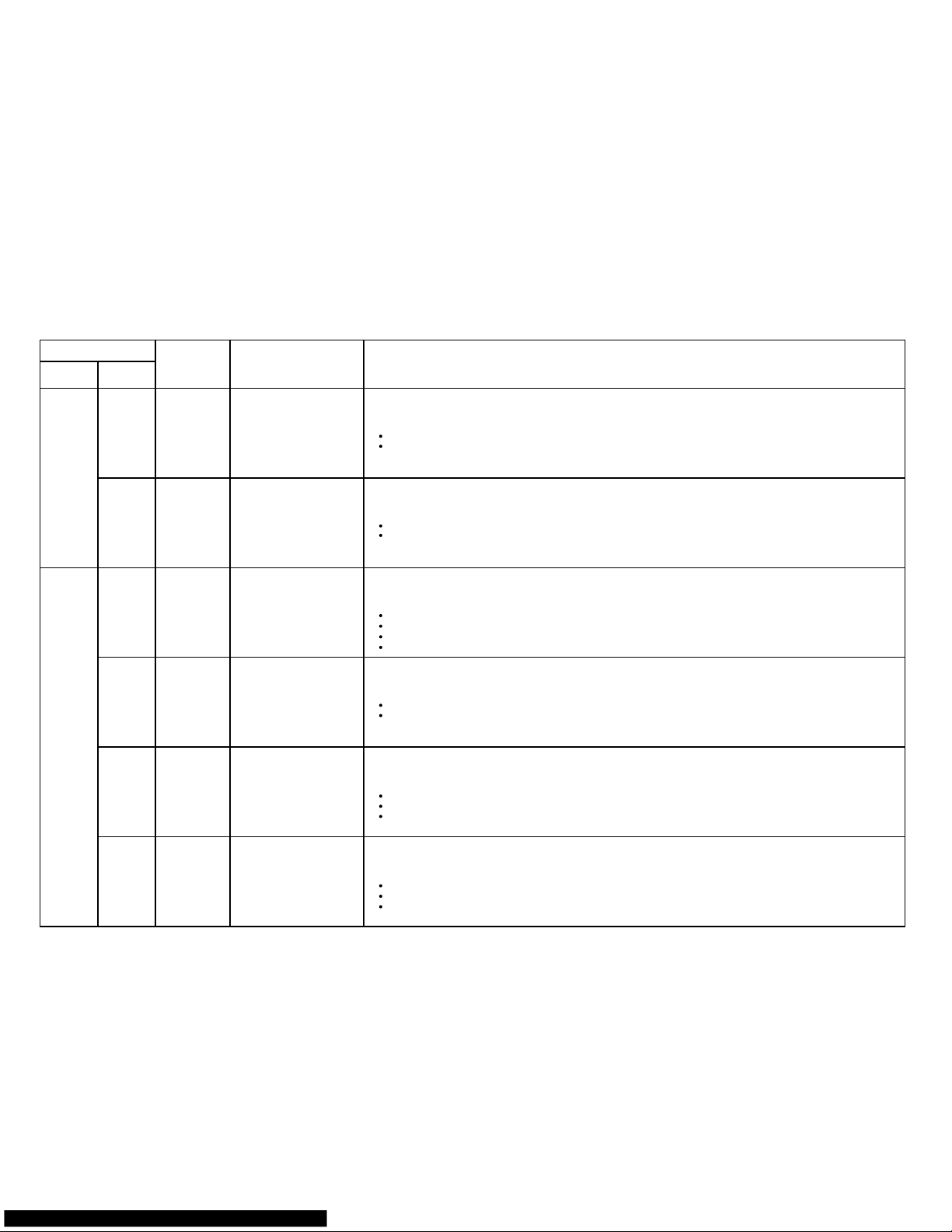
Self - diagnosis function and Checking points
Error Indication
Operation
(RED)
Timer
(GREEN)
Wired remote
controller
Error
(Protection)
Diagnosis Method
0.5 sec
7 times
The air clean operation signal was detected for 1 minute at the time of air clean mode OFF.
> All stop. Not operate remote controller.
Abnormal current value of IPM is detected.
> Permanent stop.
0.5 sec
4 times
No Display
07-05
CT error
IPM protection
Reverde-VDD permanence
stop protection
(Electric air clean power
supply circuit abnormal)
VDD permanence stop
protection
(Electric air clean)
When the air cleanness monitor trial protection operates 4 times.
> Only clean air permanent stop.
[Diagnosis Point]
The front panel is closed.
The foreign body such as dust doesn't adhere.
[Diagnosis Point]
Electric air clean defective.
Controller PCB defective.
[Diagnosis Point]
Heat radiation is blocked (inlet/outlet).
Check if outdoor fan is defetcive (does not rotate).
Controller PCB defective (Refer to after mentioned "IPM diagnosis").
Refrigeration cycle defective (Refer to after mentioned "refrigeration cycle diagnosis").
The current value during the operation after 1 minute from starting up the compressor is 0A.
> permanent stop.
[Diagnosis Point]
Check if CT wire is open.
Controller PCB defective.
21
17
18
1A
1B
The compressor speed does not synchronze with the control signal. (Including start up failure of the compressor).
> permanent stop.
[Diagnosis Point]
Check if 2-way valve or 3-way valve is left open.
Check the compressor (Winding resistance value, loose lead wire).
Refrigeration cycle defective (Refer to after mentioned "refrigerant cycle diagnosis")
Either the outdoor fan motor abnormal current or location error was detected.
> Permanent stop.
[Diagnosis Point]
Fan motor connector loose/ defective contact.
Fan motor defective.
Controller PCB defective.
Compressor location error
Outdoor fan error
(DC motor)
0.5 sec
8 times
0.5 sec
2 times
0.5 sec
3 times
0.5 sec
5 times
0.5 sec
6 times
0.5 sec
5 times
Page 50

Self - diagnosis function and Checking points
Error Indication
Operation
(RED)
Timer
(GREEN)
Wired remote
controller
Error
(Protection)
Diagnosis Method
0.5 sec
2 times
The indoor fan speed is 1/3 of the target frequency after 56 seconds from starting operation or from the time the fan mode was
changed. > Operation stop. (It releases by sending the operation stop signal from the remote controller).
The discharge temperature error is activated.
> Permanent stop.
0.5 sec
6 times
No Display
07-06
Excessive high pressure
protection on cooling
Discharge temperature
error
Indoor fan speed error
Indoor fan lock error The indoor fan speed is 0 rpm after 56 seconds from starting operation or from the time the fan mode was changed.
> Operation stop. (It releases by sending the operation stop signal from the remote controller).
[Diagnosis Point]
Fan motor connector loose /defective contact.
Fan motor defective
Controller PCB defective.
[Diagnosis Point]
Fan motor connector loose /defective contact.
Fan motor defective
Controller PCB defective.
[Diagnosis Point]
Check if 2-way valve or 3-way valve is left open.
Heat radiation is blocked (Inlet /outlet).
Check if outdoor fan is defective (does not rotate).
Refrigeration cycle defective (Refer to after mentioned "refrigerant cycle disagnosis").
Excessive high pressure protection on cooling mode has been activated.
> Compressor, outdoor fan : Off (It releases after 3 minute ST).
[Diagnosis Point]
Heat radiation is blocked (Inlet /outlet).
Check if outdoor fan is defective (does not rotate).
Refrigeration cycle defective (Refer to after mentioned "refrigerant cycle disagnosis").
No Display
0F
24
25
Excessive voltage of DC voltage on PFC circuit in inverter PCB is detected, or the excessive current in the circuit is detected.
> Permanent stop.
[Diagnosis Point]
Controller PCB defective (Refer to after mentioned "PFC circuit diagnosis")
PFC circuit error
0.5 sec
3 times
0.5 sec
2 times
0.5 sec
3 times
0.5 sec
4 times
0.5 sec
7 times
0.5 sec
8 times
Page 51
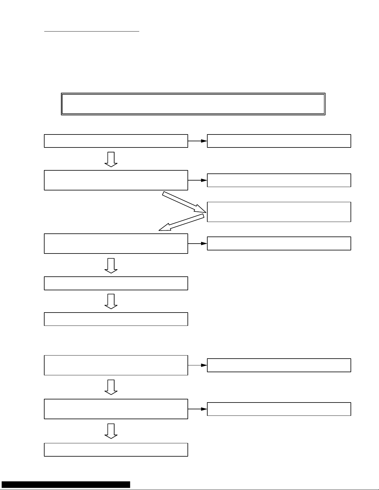
Serial Signal Receiving Error
[Check Point] Check which has a cause of error, either Indoor unit or Outdoor unit.
* Remove indoor unit front panel and cable xlampers and keep the terminal block clear so that it can be
measured with a meter.
* Remove AC power and reset the power, and press Test Operation switch on remote control.
[Check Procedure]
[Indoor Unit Check]
CAUTION: Keep out hands from terminal base and electrical components. Voltage is
applied on them and you may get electric shock.
NO
YES
07-07
[Outdoor Unit Check]
Indoor unit control unit is normal.
Check outdoor unit control unit.
Check cable wiring of terminal base of indoor
and outdoor unit correctly connected as numbered.
Does voltage AC208 to 230V appear between NO
terminal 1 and 2 of indoor unit terminal base?
Check cable wiring of terminal base.
Does indoor unit start to operate? Conduct the inspection on "no operation at all".
Outdoor unit controller PCB board failure.
Measure voltage between terminal 2 and 3 of
indoor unit terminal base. Is it normal?
Indoor unit controller PCB IC10 failure.
Does voltage AC208 to 230V appear at NO
DC voltage terminal?
Check broken fuse, wiring connection.
Does voltage AC208 to 230V appear between
terminai 4 and 5 of outdoor unit terminal base?
Check power supply connection.
NO
NO
NO
NO
YES
YES
YES
YES
YES
Page 52
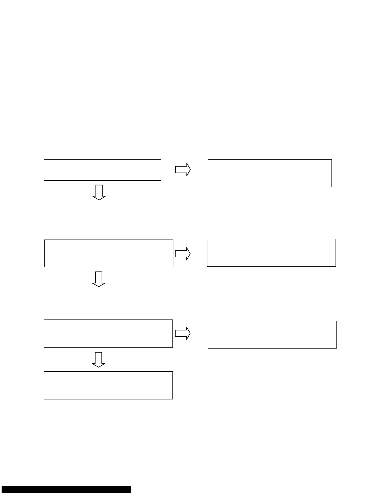
IPM Protection
[Checking Points]
Check the following points and locae the cause in the outdoor unit.
[Cause]
(1) Compressor failure
(2) Refrigeration cycle failure
(3) PC Board defective
(4) IPM defective
(5) Incorrect wiring
[First step]
Measure the DC voltage at terminals (between Electrolytic Capacitor and discharge resistance)
in the Inverter Controller Assy, and make sure it is lower than DC5V.
Check point (1)
Open the Inverter Controller Assy
Yes(Normal)
Go to Check point (2)
and check if there is abnormal points.
No(Abnormal)
Incorrect wiring > Correct and recheck
Parts touched > Correct and recheck
Parts broken > Change the broken part
Check point (2)
Turn on the power and press TEST button
Yes(Rotating)
Go to Check point (3)
on Remote Control.
No(Not rotating)
IPM or PCB defective > Replace PCB
Is the outdoor fan rotating?
Check point (3)
Operate the unit for certain time and
Yes(Operating)
The unit is normal.
check if the compressor is operating.
No(Not operating)
IPM or PCB defective > Replace PCB
Recheck
Operate the unit for certain time and Yes(Operating) > Check completed
check if the compressor is operating. No(Not operating) > Return to the start
If it is higher than 5V, wait until the discharging is over.
07-08
Page 53
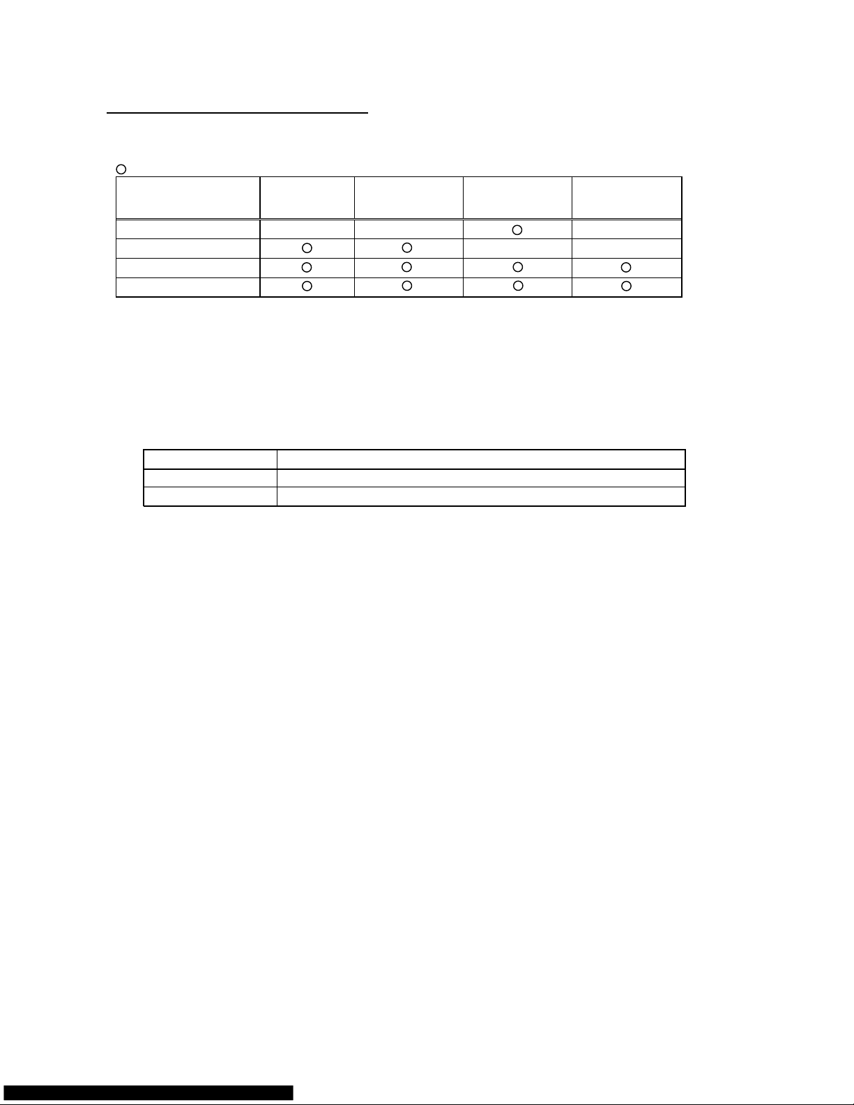
(The above resistance value is a typical value. There is some distribution. A
Trouble Shooting of Refrigerant Cycle
[Diagnosis Table for Defective Component]
: Item of most possible cause
IPM Protection
Compressor
Location error
Discharge
Temperature Error
Cooling High
Pressure
Protection
Refrigerant leak
Compressor failure(*)
EEV failure (*)
Thermistor failure (*)
(*) Trouble Shooting Method
(1) Checking method of the compressor failure
Insert the AC plug and start up the cooling operation. Input Test operation signal and check if the
compressor operates.
If it does not operate, measure the resistance value of compressor windings between U-V, V-W,
W-U.
If any of the resistance value between U-V, V-W, W-U is not same as others, the compressor is
defective.
Compressor Failure
NORMAL
ASU9/12RLQ Compressor Case Temperature at 68°F(20°C): 0.710 ohm
ASU18CL/RL Compressor Case Temperature at 68°F(20°C): 0.730 ohm
s it also changes by the
compressor temperature, the measured value may be much different from the above table when
measured right after stopping operation.)
(2) Checking method of EEV failure
- Insert the AC plug and start up the operation. Check if the EEV operates just before compressor is turned
on. (Touch EEV by hand and check it.)
If it does not operate, check if the coil or connector of EEV is removed or loose.
If it operates, check the discharge thermistor / outdoor heat exchanger thermistor / indoor heat
exchanger thermistor. (Refer to (3) for checking method.)
(3) Checking method of Thermistor
- Check each thermistor if it is removed or the connector is loose.
If there is no problem, remove the connector of the thermistor from the PCB and check the resistance
value (refer to the thermitor characteristics table).
07-09
Page 54

8 . APPENDING DATA
R410A
WALL MOUNTED type
INVERTER
1. Jumper setting of Indoor unit and Outdoor unit
2. Outdoor unit Pressure Value and Total Electric Current Curve
3. T
hermistor Resistance Values
4. Capacity/Input data
Page 55

JP (Jumper) Setting
[Indoor Unit]
ASU9/12RLQ
ASU18CL/RL
- Remote control custom code
When multiple number of indoor units are installed in the same room, erroneous receipt of the signal can
be avoided by setting up the remote control custom code separately.
To set up the remote control custom code, always set up the same code on both indoor unit PCB and
remote control PCB.
(When the indoor unit PCB is changed to Code B, it can not receive the signal unless remote control PCB
is also changed to Code B.)
Indoor Unit Remote Control
JM3(JP)
J4 (JP)
Code A (Default) YES YES
Code B NO NO
- Auto Restart
It is possible to disengage Auto Restart function if it is not needed.
Indoor Unit
JM2 (JP)
With Auto Restart function
(Default)
YES
Without Auto Restart
function
NO
[Outdoor Unit]
AOU9/12RLQ, AOU18CL/RL
JP
JM500
Normal Preheat YES
Higher Preheat NO
- it is possible to select the higher or standard level of preheating function.
- When it is set up at the higher level of preheat, the magnetic noise of the compressor becomes higher.
08-01
Page 56
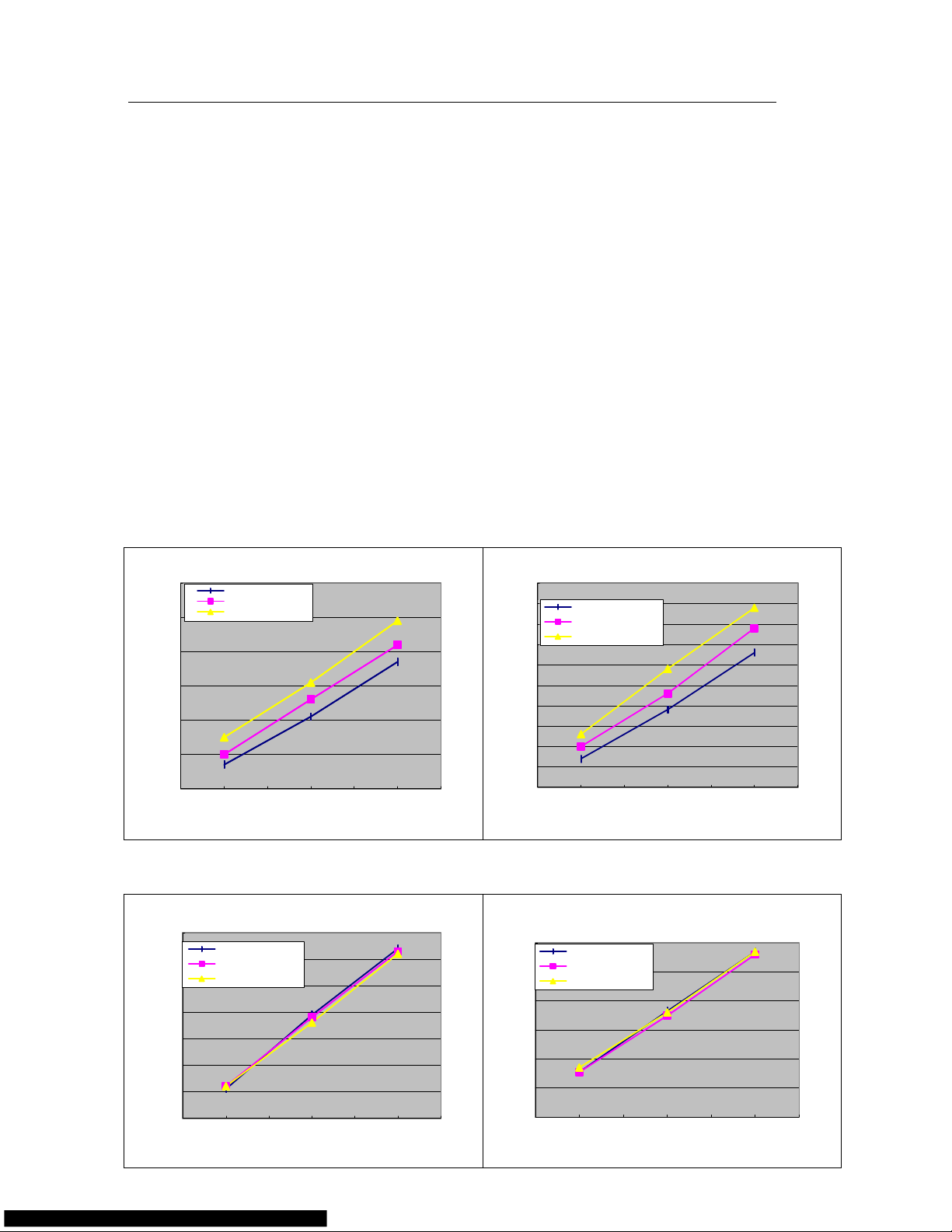
Outdoor Unit Low Pressure Value and Outdoor Total Electric Current Curve (Cooling)
Model Name : ASU9RLQ, ASU12RLQ
[Condition]
Ambient
temperature
Indoor / Outdoor - Same temperature
Refrigerant
amount
Standard amount
Piping 7.5m (Height difference 1m)
Power
voltage
60Hz - 230V
Operation
condition
TEST mode (Cooling), Hi Fan, Horizontal direction, Front air flow
Measuring
method
Caution
Start operation with the condition of the Indoor Unit air filter clean.
[Constant Frequency Operation Method (Test mode)]
1. Operate on Colling mode, and press TEST button of remote control.
2. Operate continuously for 30 minutes. (After 60 minutes of operation, Test mode is released automatically.)
(1) Indoor/Outdoor Temperature - Outdoor Low Pressure Curve
ASU9RLQ series ASU12RLQ series
(2) Indoor/Outdoor Temperature - Outdoor Total Electric Current Curve
ASU9RLQ series ASU12RLQ series
Measure the low pressure with the pressure meter at the service valve. Measure the
outdoor unit overall current with the current clamp meter at Power Cable.
0.80
0.90
1.00
1.10
1.20
1.30
1.40
63.5
(17.5)
68
(20)
72.5
(22.5)77(25)
81.5
(27.5)86(30)
90.5
(32.5)
In/Outdoor ambient temperature °F(°C)
Outdoor High Pressure (Mpa)
Relative Humidity 50%
Relative Humidity 60%
Relative Humidity 70%
2.00
2.10
2.20
2.30
2.40
2.50
2.60
2.70
In/Outdoor ambient temperature °F(°C)
Outdoor Total Electric Current (A)
Relative Humidity 50%
Relative Humidity 60%
Relative Humidity 70%
0.7
0.75
0.8
0.85
0.9
0.95
1
1.05
1.1
1.15
1.2
In/Outdoor ambient temperature °F(°C)
Outdoor High Pressure (MPa)
Relative Humidity 50%
Relative Humidity 60%
Relative Humidity 70%
3
3.2
3.4
3.6
3.8
4
4.2
In/Outdoor ambient temperature °F(°C)
Outdoor Total Electric Current (A)
Relative Humidity 50%
Relative Humidity 60%
Relative Humidity 70%
length
08-02
63.5
(17.5)
68
(20)
72.5
(22.5)77(25)
81.5
(27.5)86(30)
90.5
(32.5)
63.5
(17.5)68(20)
72.5
(22.5)77(25)
81.5
(27.5)86(30)
90.5
(32.5)
63.5
(17.5)68(20)
72.5
(22.5)77(25)
81.5
(27.5)86(30)
90.5
(32.5)
Page 57
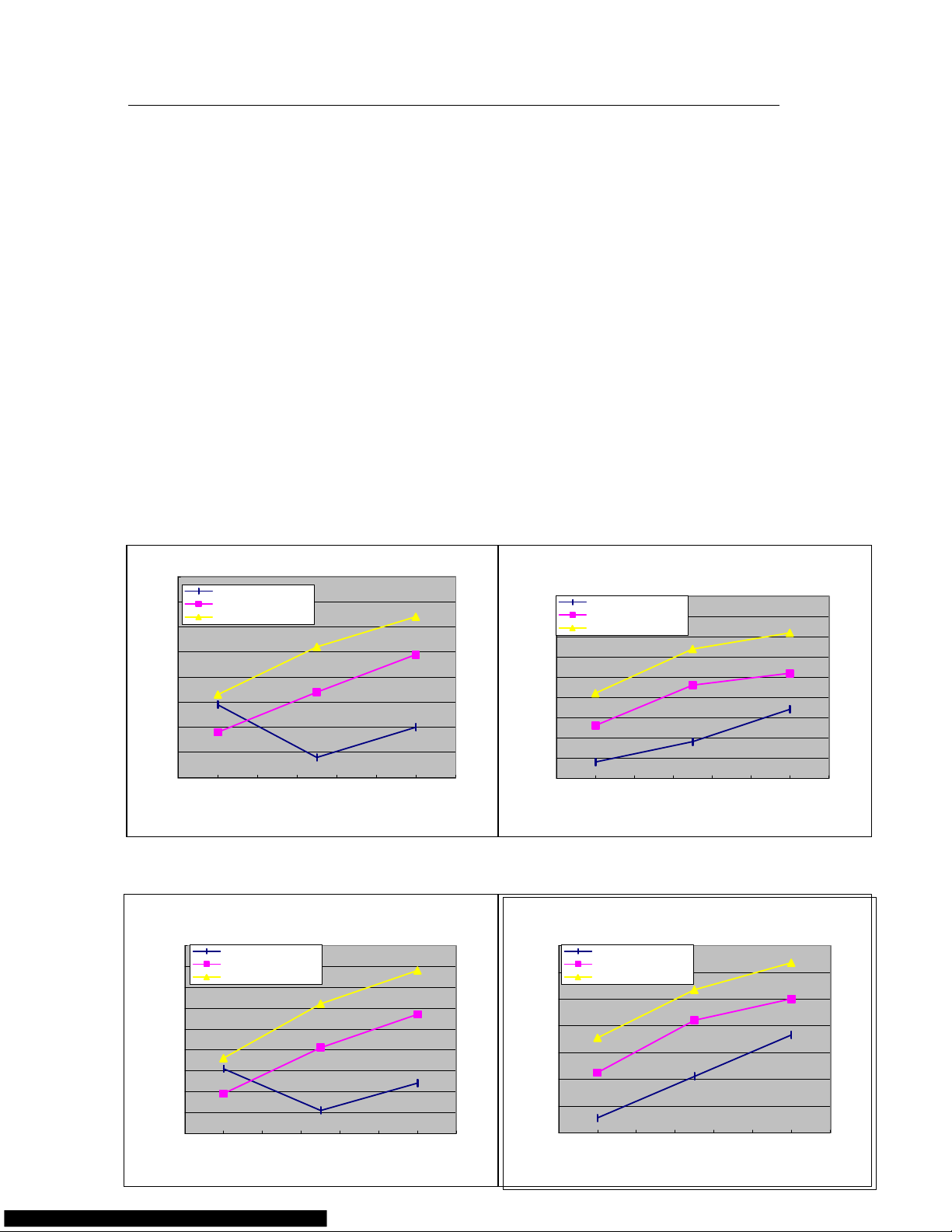
Outdoor Unit High Pressure Value and Outdoor Total Electric Current Curve (Heating)
Model Name : ASU9RLQ, ASU12RLQ
[Condition]
Ambient
temperature
Indoor 15 - 23degC, Outdoor 2 - 12degC
Refrigerant
amount
Standard amount
Piping
7.5m (Height difference 1m)
Power
voltage
60Hz - 230V
Operation
condition
TEST mode (Heating), Hi Fan, Lower direction, Front air flow
Measuring
method
Caution
Start operation with the condition of the Indoor Unit air filter clean.
[Constant Frequency Operation Method (Test mode)]
1. Operate on Heating mode, and press TEST button of remote control.
2. Operate continuously for 30 minutes. (After 60 minutes of operation, Test mode is released automatically.)
(1) Indoor/Outdoor Temperature - Outdoor High Pressure Curve
ASU9RLQ series
ASU12RLQ series
(2) Indoor/Outdoor Temperature - Outdoor Total Electric Current Curve
ASU9RLQ series
ASU12RLQ series
Measure the high pressure with the pressure meter at the service valve. Measure the
outdoor unit overall current with the current clamp meter at Power Cable.
2.10
2.20
2.30
2.40
2.50
2.60
2.70
2.80
2.90
32
(0)
35.6
(2)
39.2
(4)
42.8
(6)
46.4
(8)50(10)
53.6
(12)
57.2
(14)
Outdoor ambient temperature °F(°C)
Outdoor High Pressure (Mpa)
Indoor inlet temp 59°F(15°C)
Indoor inlet temp 68°F(20°C)
Indoor inlet temp 74°F(23°C)
3.50
3.60
3.70
3.80
3.90
4.00
4.10
4.20
4.30
4.40
Outdoor ambient temperature °F(°C)
Outdoor Total Electric Current (A)
2.40
2.50
2.60
2.70
2.80
2.90
3.00
3.10
3.20
3.30
Outdoor ambient temperature °F(°C)
Outdoor High Pressure (Mpa)
5.00
5.20
5.40
5.60
5.80
6.00
6.20
6.40
Outdoor ambient temperature °F(°C)
Outdoor Total Electric Current (A)
length
08-03
32
(0)
35.6
(2)
39.2
(4)
42.6
(6)
46.4
(8)50(10)
53.6
(12)
57.2
(14)
32
(0)
35.6
(2)
39.2
(4)
42.8
(6)
46.4
(8)50(10)
53.6
(12)
57.2
(14)
32
(0)
35.6
(2)
39.2
(4)
42.6
(6)
46.4
(8)50(10)
53.6
(12)
57.2
(14)
Indoor inlet temp 59°F(15°C)
Indoor inlet temp 68°F(20°C)
Indoor inlet temp 74°F(23°C)
Indoor inlet temp 59°F(15°C)
Indoor inlet temp 68°F(20°C)
Indoor inlet temp 74°F(23°C)
Indoor inlet temp 59°F(15°C)
Indoor inlet temp 68°F(20°C)
Indoor inlet temp 74°F(23°C)
Page 58

Outdoor Unit Low Pressure Value and Outdoor Total Electric Current Curve (Cooling)
Model Name : ASU18CL, ASU18RL
[Condition]
Ambient
temperature
Indoor / Outdoor - Same temperature
Refrigerant
amount
Standard amount
Piping 7.5m (Height difference 1m)
Power
voltage
60Hz - 230V
Operation
condition
TEST mode (Cooling), Hi Fan, Horizontal direction, Front air flow
Measuring
method
Caution
Start operation with the condition of the Indoor Unit air filter clean.
[Constant Frequency Operation Method (Test mode)]
1. Operate on Colling mode, and press TEST button of remote control.
2. Operate continuously for 30 minutes. (After 60 minutes of operation, Test mode is released automatically.)
(1) Indoor/Outdoor Temperature - Outdoor Low Pressure Curve
ASU18CL/RL series
(2) Indoor/Outdoor Temperature - Outdoor Total Electric Current Curve
ASU18CL/RL series
Measure the low pressure with the pressure meter at the service valve. Measure the
outdoor unit overall current with the current clamp meter at Power Cable.
0.7
0.8
0.9
1
1.1
1.2
1.3
In/Outdoor ambient temperature °F(°C)
Outdoor Low Pressure (Mpa)
Relative Humidity 50%
Relative Humidity 60%
Relative Humidity 70%
4
4.5
5
5.5
6
In/Outdoor ambient temperature °F(°C)
Outdoor Total Electric Current (A)
Relative Humidity 50%
Relative Humidity 60%
Relative Humidity 70%
length
08-04
59
(15)
68
(20)
77
(25)
86
(30)
95
(35)
59
(15)
68
(20)
77
(25)
86
(30)
95
(35)
Page 59

Outdoor Unit High Pressure Value and Outdoor Total Electric Current Curve (Heating)
Model Name : AS18RL
[Condition]
Ambient
temperature
Indoor 15 - 23degC, Outdoor 2 - 12degC
Refrigerant
amount
Standard amount
Piping 7.5m (Height difference 1m)
Power
voltage
60Hz - 230V
Operation
condition
TEST mode (Heating), Hi Fan, Lower direction, Front air flow
Measuring
method
Caution
Start operation with the condition of the Indoor Unit air filter clean.
[Constant Frequency Operation Method (Test mode)]
1. Operate on Heating mode, and press TEST button of remote control.
2. Operate continuously for 30 minutes. (After 60 minutes of operation, Test mode is released automatically.)
(1) Indoor/Outdoor Temperature - Outdoor High Pressure Curve
ASU18RL
(2) Indoor/Outdoor Temperature - Outdoor Total Electric Current Curve
ASU18RL
Measure the high pressure with the pressure meter at the service valve. Measure the
outdoor unit overall current with the current clamp meter at Power Cable.
3
3.2
3.4
3.6
3.8
4
32
(0)
41
(5)
50
(10)
59
(15)
Outdoor ambient temperature °F(°C)
High-pressure of outdoor unit (Mpa)
6.5
7
7.5
8
8.5
9
Outdoor ambient temperature °F(°C)
Outdoor Total Electric Current (A)
length
Indoor inlet temp :59°F(15°C)
Indoor inlet temp :68°F(20°C)
Indoor inlet temp :73°F(23°C)
08-05
32
(0)
41
(5)
50
(10)
59
(15)
Indoor inlet temp :59°F(15°C)
Indoor inlet temp :68°F(20°C)
Indoor inlet temp :73°F(23°C)
Page 60

0.00
5.00
10.00
15.00
20.00
25.00
30.00
35.00
40.00
32
(0)50(10)68(20)86(30)
104
(40)
122
(50)
140
(60)
0.00
20.00
40.00
60.00
80.00
100.00
120.00
140.00
160.00
180.00
32
(0)
68
(20)
104
(40)
140
(60)
176
(80)
0.00
20.00
40.00
60.00
80.00
100.00
120.00
140.00
160.00
180.00
32
(0)68(20)
104
(40)
140
(60)
176
(80)
212
(100)
248
(120)
0.00
10.00
20.00
30.00
40.00
50.00
0.00
20.00
40.00
60.00
80.00
100.00
120.00
Thermistor resistance values
Characteristics of room temperature thermistor
Resistance (k )
Temperature °F(°C)
Characteristics of heat exchanger thermistor (Indoor)
Resistance (k )
Temperature °F(°C)
Characteristics of discharge thermistor
Resistance (k )
Temperature °F(°C)
Resistance (k )
Temperature °F(°C)
Characteristics of heat exchanger thermistor (Outdoor)
Resistance (k )
Temperature °F(°C)
Characteristics of outdoor temperature thermistor
08-06
Temp °F(°C) Voltage (V)
32.00
41.00
50.00
59.00
68.00
77.00
86.00
95.00
104.00
113.00
122.00
131.00
140.00
149.00
158.00
167.00
176.00
185.00
194.00
203.00
212.00
(0.00)
(5.00)
(10.00)
(15.00)
(20.00)
(25.00)
(30.00)
(35.00)
(40.00)
(45.00)
(50.00)
(55.00)
(60.00)
(65.00)
(70.00)
(75.00)
(80.00)
(85.00)
(90.00)
(95.00)
(100.00)
33.62
25.93
20.18
15.84
12.54
10.00
8.04
6.51
5.30
4.35
3.59
2.98
2.47
2.09
1.76
1.49
1.27
1.09
0.93
0.81
0.70
1.15
1.39
1.66
1.94
2.22
2.50
2.77
3.03
3.27
3.48
3.68
3.85
4.00
4.14
4.25
4.35
4.44
4.51
4.57
4.63
4.67
Room temperature thermistor
Resistance k
Temp °F(°C) Voltage (V)
32.00
41.00
50.00
59.00
68.00
77.00
86.00
95.00
104.00
113.00
122.00
131.00
140.00
149.00
158.00
167.00
176.00
185.00
194.00
203.00
212.00
(0.00)
(5.00)
(10.00)
(15.00)
(20.00)
(25.00)
(30.00)
(35.00)
(40.00)
(45.00)
(50.00)
(55.00)
(60.00)
(65.00)
(70.00)
(75.00)
(80.00)
(85.00)
(90.00)
(95.00)
(100.00)
0.18
0.24
0.30
0.31
0.38
0.47
0.70
0.84
0.99
1.16
1.34
1.54
1.74
1.95
2.16
2.36
2.57
2.76
2.95
3.13
3.30
Discharge thermistor
Resistance k
221.00 (105.00) 3.45
230.00 (110.00) 3.60
239.00 (115.00) 3.73
248.00 (120.00)
175.70
134.93
104.59
81.79
64.50
51.27
41.07
33.13
26.91
22.01
18.10
14.98
12.47
10.44
8.78
7.42
6.31
5.38
4.61
3.97
3.43
2.98
2.59
2.26
1.99 3.85
Temp °F(°C) Voltage (V)
32.00
41.00
50.00
59.00
68.00
77.00
86.00
95.00
104.00
113.00
122.00
131.00
140.00
149.00
158.00
167.00
176.00
185.00
194.00
203.00
212.00
(0.00)
(5.00)
(10.00)
(15.00)
(20.00)
(25.00)
(30.00)
(35.00)
(40.00)
(45.00)
(50.00)
(55.00)
(60.00)
(65.00)
(70.00)
(75.00)
(80.00)
(85.00)
(90.00)
(95.00)
(100.00)
176.03
134.23
103.34
80.28
62.91
49.70
39.57
31.74
25.64
20.85
17.06
14.10
11.64
9.69
8.12
6.83
5.78
4.91
4.19
3.59
3.09
1.10
1.36
1.63
1.92
2.21
2.51
2.79
3.06
3.30
3.53
3.73
3.90
4.55
4.19
4.30
4.40
4.48
4.55
4.61
4.66
4.71
Indoor heat exchanger thermistor
Resistance k
Temp °F(°C) Voltage (V)
49.20
36.58
27.51
20.91
16.05
12.44
9.73
7.67
6.10
4.89
3.95
3.21
2.62
2.16
1.79
1.49
1.25
1.05
0.89
0.76
0.65
2.66
3.02
3.35
3.64
3.89
4.09
4.26
4.40
4.51
4.60
4.67
4.73
4.78
4.81
4.85
4.87
4.89
4.91
4.92
4.93
4.94
Outdoor heat exchanger thermistor
Resistance k
0.56 4.95
0.48 4.96
0.41 4.96
32.00
41.00
50.00
59.00
68.00
77.00
86.00
95.00
104.00
113.00
122.00
131.00
140.00
149.00
158.00
167.00
176.00
185.00
194.00
203.00
212.00
(0.00)
(5.00)
(10.00)
(15.00)
(20.00)
(25.00)
(30.00)
(35.00)
(40.00)
(45.00)
(50.00)
(55.00)
(60.00)
(65.00)
(70.00)
(75.00)
(80.00)
(85.00)
(90.00)
(95.00)
(100.00)
-4.00 (-20.00)
5.00 (-15.00)
14.00 (-10.00)
23.00 (-5.00)
0.36 4.97
Temp °F(°C) Voltage (V)
1.25
1.56
1.90
2.26
2.61
2.94
3.25
3.52
3.76
3.97
4.14
4.28
4.41
4.51
4.59
4.65
4.71
4.76
4.79
4.83
4.85
Outdoor temperature thermistor
Resistance k
4.87
4.89
4.91
115.24
84.21
62.28
46.58
35.21
26.88
20.72
16.12
12.64
10.00
7.97
6.40
5.18
4.21
3.45
2.85
2.36
1.97
1.65
1.39
1.18
1.00
0.85
0.73
0.63 4.92
32.00
41.00
50.00
59.00
68.00
77.00
86.00
95.00
104.00
113.00
122.00
131.00
140.00
149.00
158.00
167.00
176.00
185.00
194.00
203.00
212.00
(0.00)
(5.00)
(10.00)
(15.00)
(20.00)
(25.00)
(30.00)
(35.00)
(40.00)
(45.00)
(50.00)
(55.00)
(60.00)
(65.00)
(70.00)
(75.00)
(80.00)
(85.00)
(90.00)
(95.00)
(100.00)
-4.00 (-20.00)
5.00 (-15.00)
14.00 (-10.00)
23.00 (-5.00)
32
(0)68(20)
104
(40)
140
(60)
176
(80)
-4
(-20)
32
(0)68(20)
104
(40)
140
(60)
-4
(-20)
Page 61

ASU9RLQ Capacity/Input data
<Capacity>
<Input>
Defrosting operation is performed when temperature is less than 42 degrees F.
Frost appears on an outdoor unit heat exchanger at 42 or less degrees F.
Solid line:Integral capacity/Input containing the defrosting cycle.
Dotted line:Capacity/Input which does not contain the defrosting cycle.
Heating
40%
50%
60%
70%
80%
90%
100%
110%
120%
130%
140%
150%
160%
170%
180%
Outdoor DB( F)
Capacity(%)
70%
80%
90%
100%
110%
120%
130%
140%
150%
160%
170%
180%
190%
200%
210%
220%
Outdoor DB( F)
Input(%)
32 41 50 59 68 7723145
Rated
operation
75
75
IndoorDB:70 F
Maximum
42
42
IndoorDB:70 F
Without Frost
Without Frost
With Frost
32 41
50
59
68
7723
145
operation
Maximum
operation
Rated
operation
Without Frost
Without Frost
With Frost
*
*
*
08-07
Page 62

60%
70%
80%
90%
100%
110%
120%
130%
140%
150%
14 32 50 68 86 104
30%
40%
50%
60%
70%
80%
90%
100%
110%
120%
130%
14 32 50 68 86 104
Indoor:80/65
115
115
Indoor:80/65
<Capacity>
<Input>
Both capacity and input change largely when temperature is 50 or less degrees F, as outdoor fan speed
is decreased due to low ambient temperature cooling control.
Both capacity and input change more largely at less than 32 degrees F of ambient temperature as
outdoor fan speed is decreased further.
Cooling
Outdoor DB( F)
Capacity(%)
Input(%)
Outdoor DB( F)
*
*
08-08
Page 63

40%
50%
60%
70%
80%
90%
100%
110%
120%
130%
140%
150%
Capacity(%)
32 50 59 68
7723
145
41
70%
80%
90%
100%
110%
120%
130%
140%
150%
160%
170%
180%
Input(%)
32
41 50
59
68
7723
145
75
75
42
42
ASU12RLQ Capacity/Input data
<Capacity>
Heating
operation
IndoorDB:70 F
Without Frost
Without Frost
With Frost
Maximum
operation
Rated
<Input>
Maximum
operation
Rated
operation
Without Frost
Without Frost
With Frost
Defrosting operation is performed when temperature is less than 42 degrees F.
Frost appears on an outdoor unit heat exchanger at 42 or less degrees F.
Solid line:Integral capacity/Input containing the defrosting cycle.
Dotted line:Capacity/Input which does not contain the defrosting cycle.
*
*
*
Outdoor DB( F)
Outdoor DB( F)
IndoorDB:70 F
08-09
Page 64

60%
70%
80%
90%
100%
110%
120%
130%
140%
150%
Capacity(%)
14 32 50 68 86 104
30%
40%
50%
60%
70%
80%
90%
100%
110%
120%
Input(%)
14 32 50 68 86 104
115
66
66
115
<Capacity>
<Input>
Cooling
Indoor:80/65
Indoor:80/65
Outdoor DB( F)
Outdoor DB( F)
Both capacity and input change largely when temperature is 50 or less degrees F, as outdoor fan speed
is decreased due to low ambient temperature cooling control.
Both capacity and input change more largely at less than 32 degrees F of ambient temperature as
outdoor fan speed is decreased further.
*
*
Both capacity and input decrease when temperature is 66 or less degrees F, for compressor
frequency restrictions operate.
Both capacity and input decrease when temperature is 104 or more degrees F, as compressor speed is
decreased due to current release protection.
*
*
08-10
Page 65
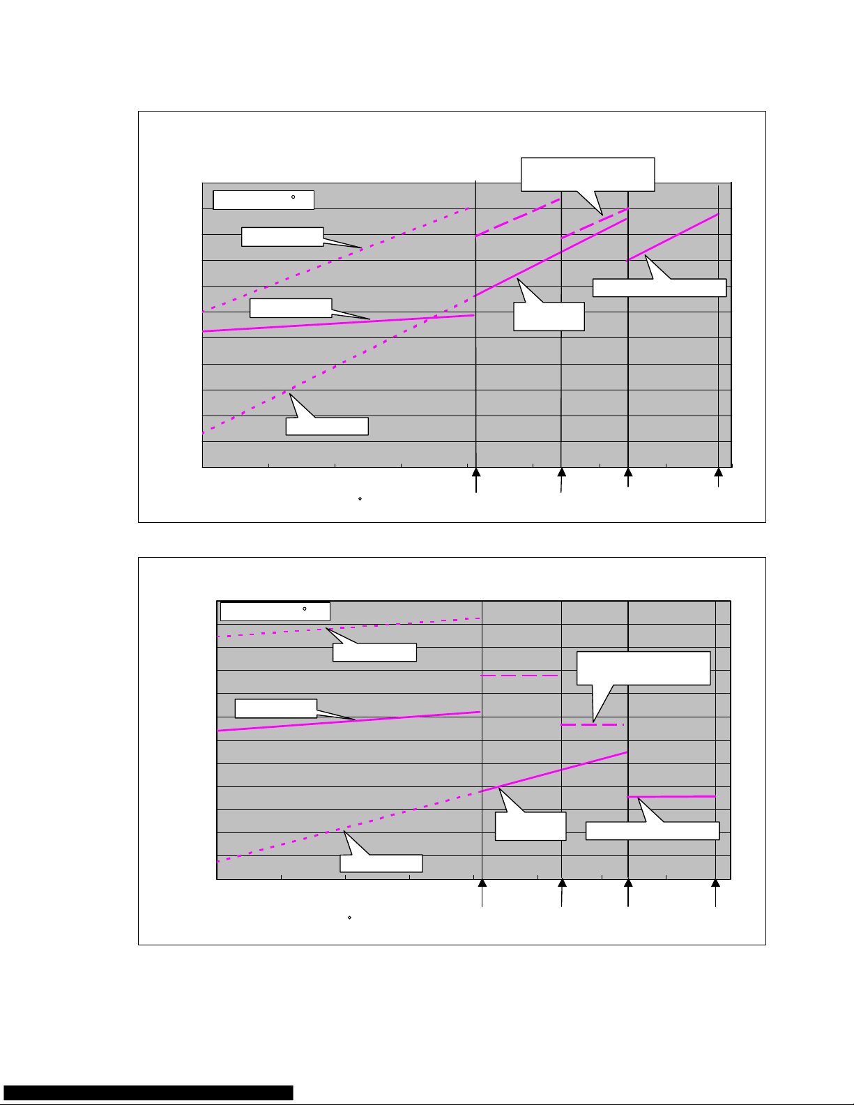
30%
40%
50%
60%
70%
80%
90%
100%
120%
110%
130%
140%
Capacity(%)
42
7563
54
32 41 50
59 68
772314
5
60%
70%
80%
90%
100%
110%
120%
130%
140%
150%
160%
170%
180%
Input(%)
42 75
63
54
32 41 50 59 68 772314
5
ASU18RL Capacity/Input data
<Capacity>
Heating
operation
IndoorDB:70 F
Without Frost
Without Frost
Without Frost
Without Frost
With Frost
With Frost
Maximum operation
Current release works
Maximum operation
Current release works
Current release works
Current release works
Rated
operation
Rated
IndoorDB:70 F
Outdoor DB( F)
Outdoor DB( F)
Defrosting operation is performed when temperature is less than 42 degrees F.
Frost appears on an outdoor unit heat exchanger at 42 or less degrees F.
Solid line:Integral capacity/Input containing the defrosting cycle.
Dotted line:Capacity/Input which does not contain the defrosting cycle.
*
*
*
<Input>
08-11
Page 66

60%
70%
80%
90%
100%
110%
120%
130%
140%
150%
Capacity(%)
66
11532 50 68 10486
14
20%
30%
40%
50%
60%
70%
80%
90%
100%
110%
120%
Input(%)
66
32 50 68 1048614 115
Indoor:80/65
Indoor:80/65
<Capacity>
<Input>
Cooling
Outdoor DB( F)
Outdoor DB( F)
Both capacity and input change largely when temperature is 50 or less degrees F, as outdoor fan speed
is decreased due to low ambient temperature cooling control.
Both capacity and input change more largely at less than 32 degrees F of ambient temperature as
outdoor fan speed is decreased further.
*
*
Both capacity and input decrease when temperature is 66 or less degrees F, for compressor
frequency restrictions operate.
Both capacity and input decrease when temperature is 104 or more degrees F, as compressor speed is
decreased due to current release protection.
*
*
08-12
Page 67

9 . REPLACEMENT PARTS
R410A
WALL MOUNTED type
INVERTER
Page 68

REPLACEMENT PARTS
09-01
Models : ASU9RLQ
ASU12RLQ
Page 69
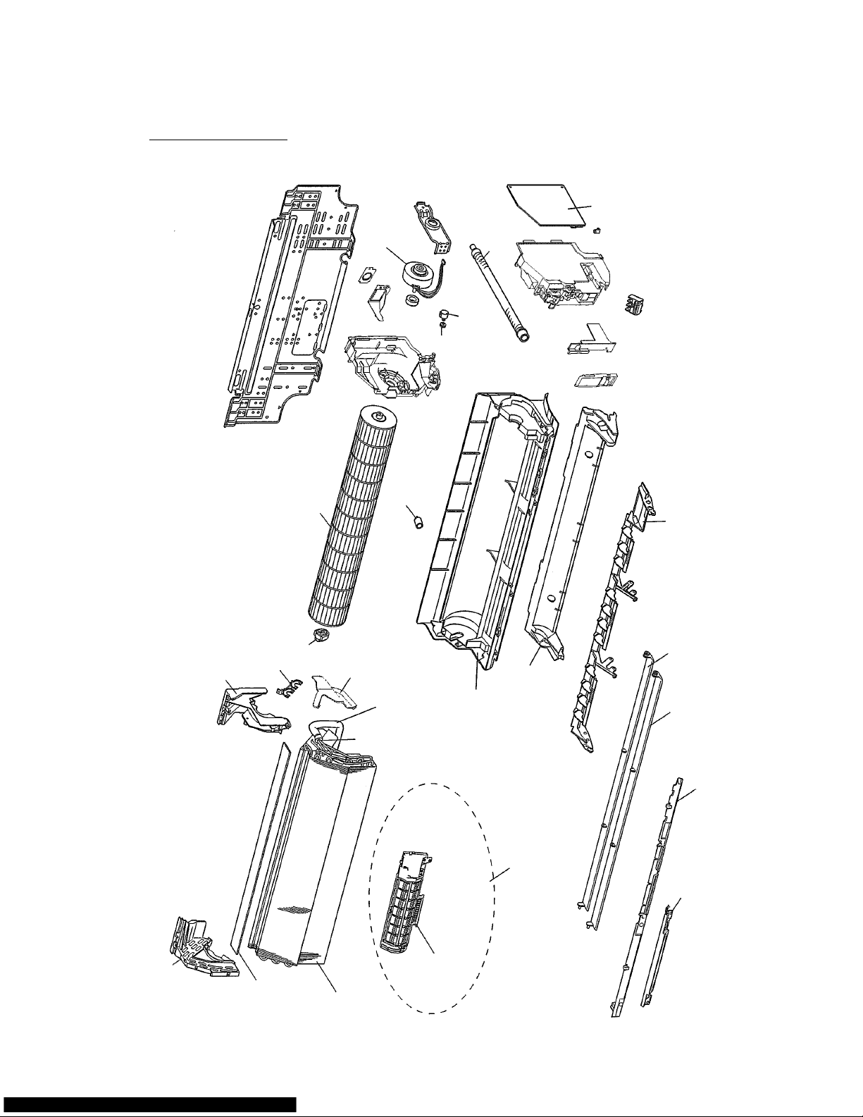
REPLACEMENT PARTS
09-02
Models : ASU9RLQ
ASU12RLQ
Page 70

REPLACEMENT PARTS
09-03
Models : AOU9RLQ
AOU12RLQ
Page 71
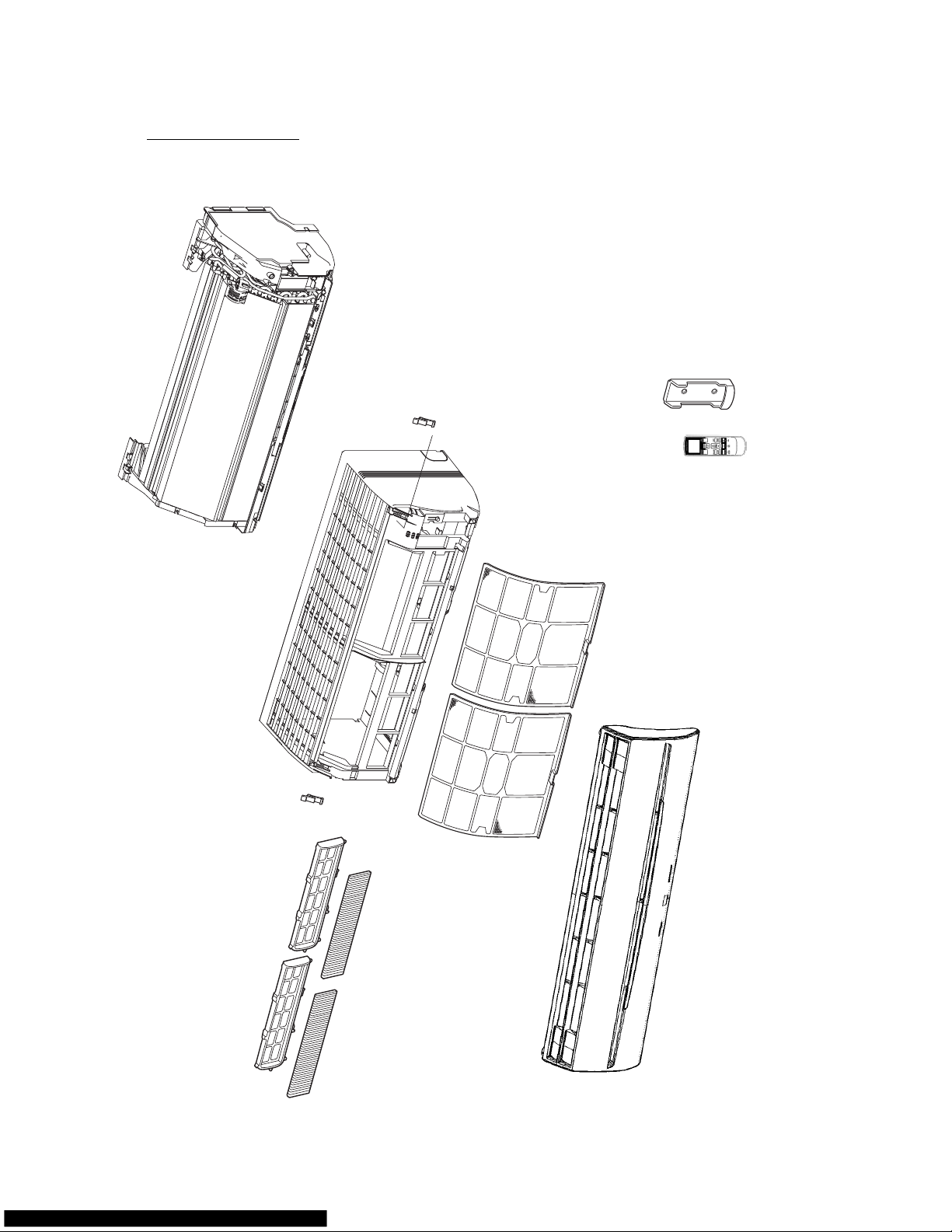
REPLACEMENT PARTS
09-04
Models : ASU18CL
ASU18RL
Page 72
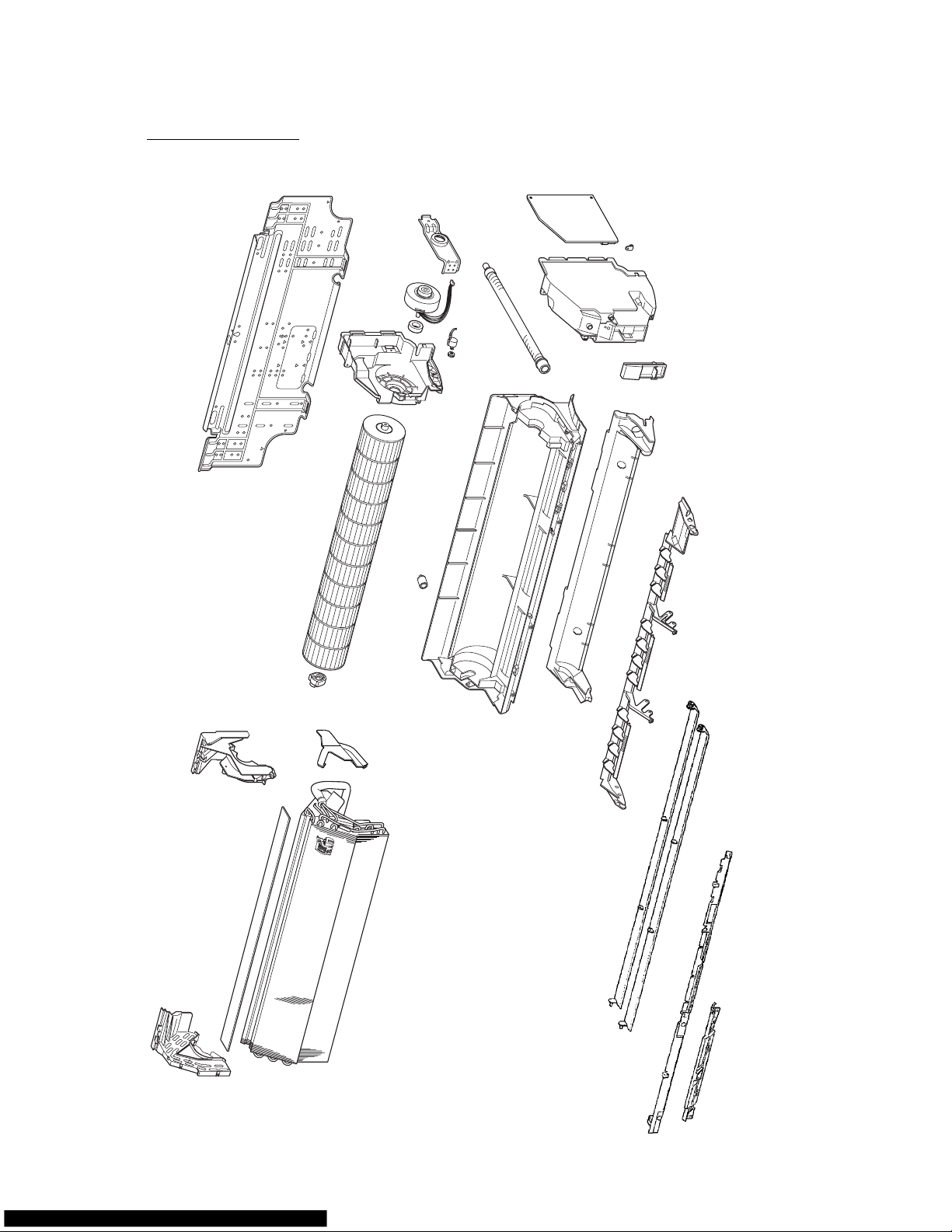
REPLACEMENT PARTS
09-05
Models : ASU18CL
ASU18RL
Page 73
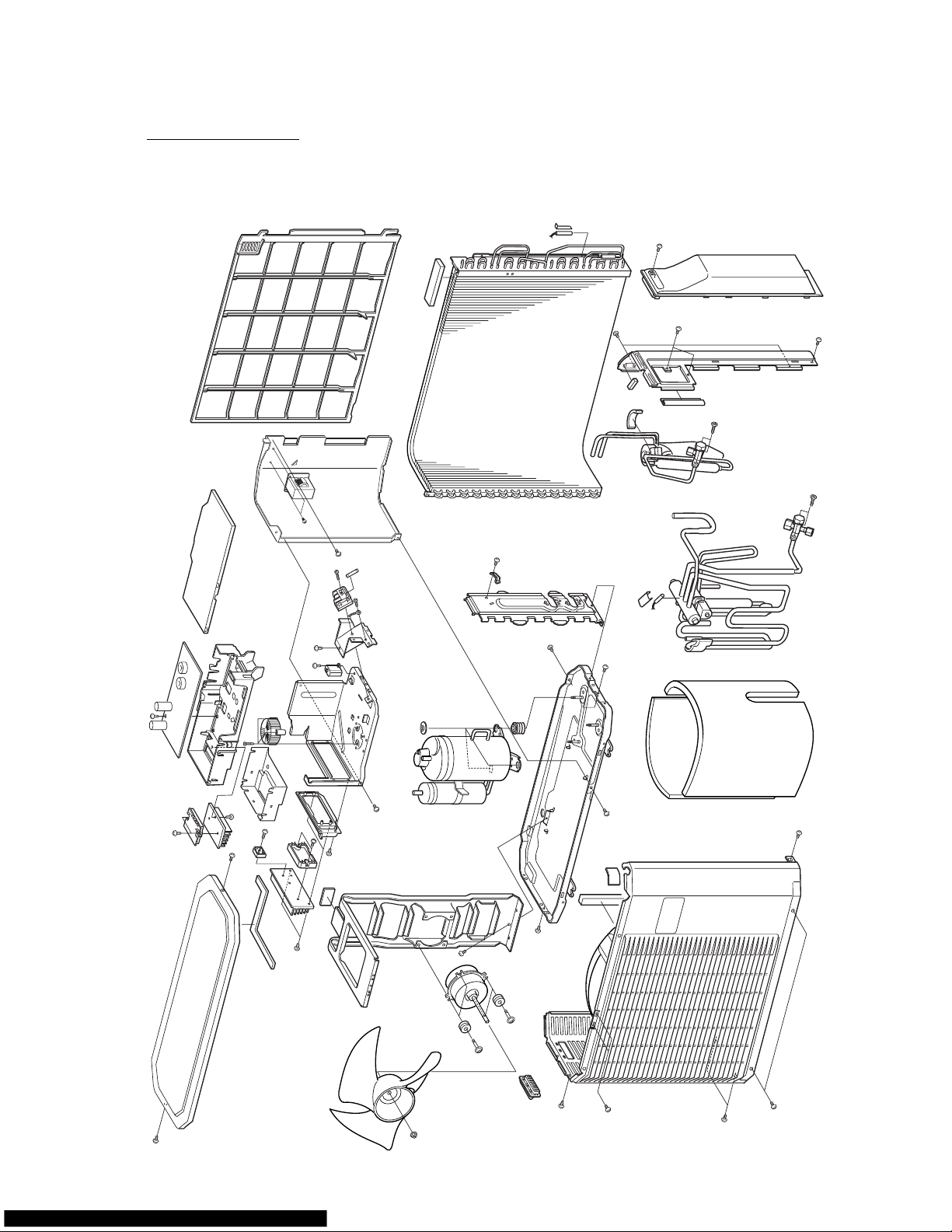
REPLACEMENT PARTS
09-06
Models : ASU18CL
ASU18RL
Page 74

REPLACEMENT PARTS
09-07
PROCESS ATTACHMENT OF INVERTER ASSY
INVERTER ASSY
Tap tight screw
(TERMINAL BRACKET)
Do not run up the terminal board mounting metal
on 2 location of hook.
THERMISTOR (OUT TEMP) is passed here.
(SEPARATER)
1
1
2
2
A
A
Page 75

REPLACEMENT PARTS
09-08
PROCESS
1
8
6
6
5
4
4
3
2
1
2
3
4
5
6
7
8
The leads are connected with INVERTER ASSY
MOTOR LEAD
THERMISTOR ASSY (COND, DIS)
THERMISTOR (OUT TEMP)
SOLENOID LEAD
COIL (EXP VLV) LEAD
COMP LEAD
WIRE CLAMPER
REACTOR LEAD
Cross and
Run the wire in front of bytly rubber sheet.
A
A
B
4
4
8
is fixed to HOLDER
Page 76

REPLACEMENT PARTS
09-09
PROCESS
7
6
7
The leads are connected with INVERTER ASSY
(TERMINAL COVER)
PCB side
COMP side
(BINDER)
B
D
D
E
E
0~10mm
COMP LEAD is passed TERMINAL COVER the under.
Page 77

REPLACEMENT PARTS
09-10
PROCESS
1
1
2
3
4
Fixing of Thermistor lead and motor lead.
THERMISTOR ASSY (SUC/DIS)
THERMISTOR (OUT TEMP)
MOTOR LEAD
COIL(EXP VLV)
0~5mm
200~230mm
10 10mm
E - E
B - B
190~220mm
160~190mm
120~140mm
B B
AA
1
2
2
2
4
4
4
3
3
3
1
1
1
Page 78

10 . INSTALLATION MANUAL
R410A
WALL MOUNTED type
INVERTER
Page 79
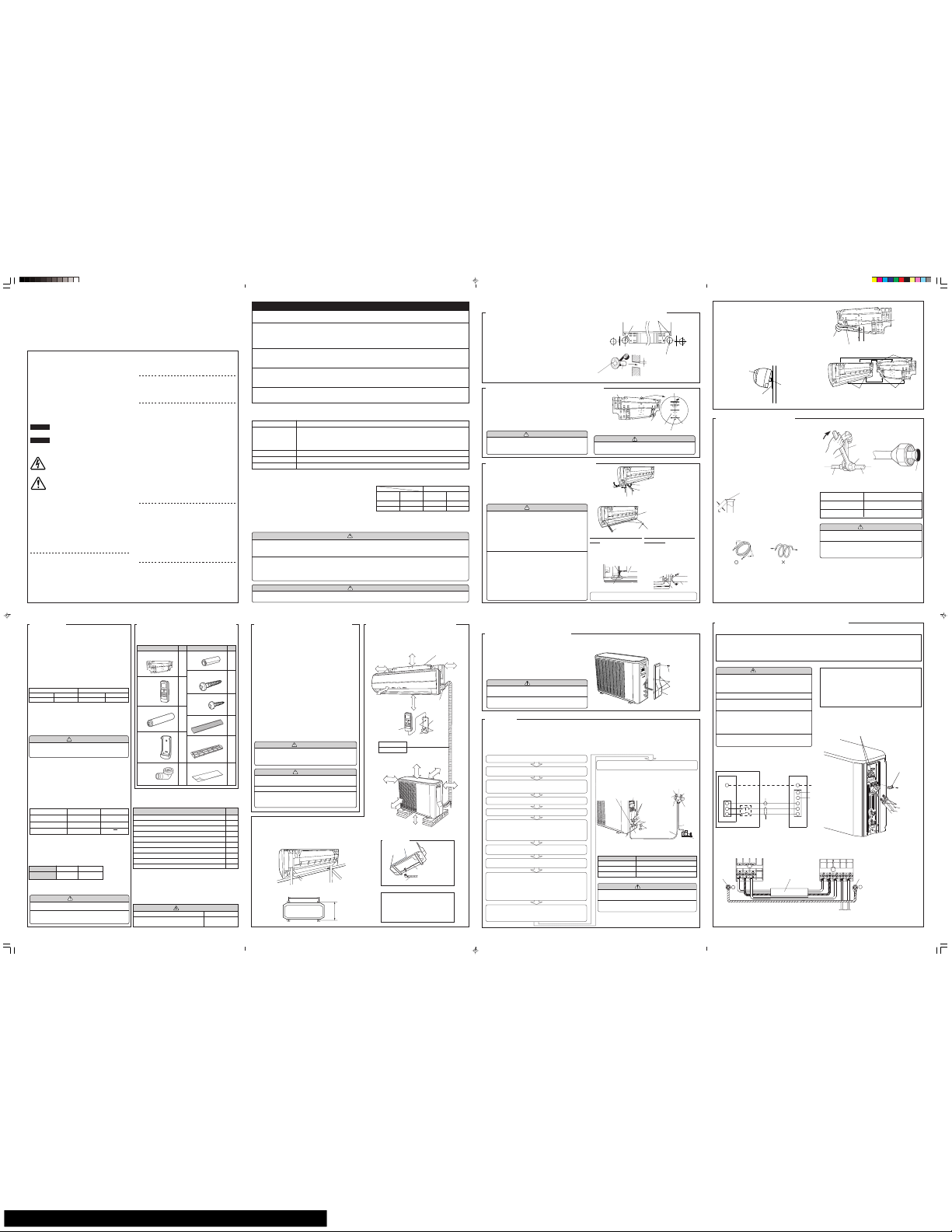
12
3
4
12
3
45
G
G
SPLIT TYPE ROOM AIR CONDITIONER
INSTALLATION MANUAL
(P/N 9315140050-01) ENGLISH
(MODEL: ASU18RL/AOU18RL; ASU18CL/AOU18CL)
IMPORTANT!
Please Read Before Starting
This air conditioning system meets strict safety and operating standards.
As the installer or service person, it is an important part of your job to
install or service the system so it operates safely and efficiently.
For safe installation and trouble-free operation, you must:
• Carefully read this instruction booklet before beginning.
• Follow each installation or repair step exactly as shown.
• Observe all local, state, and national electrical codes.
• Pay close attention to all danger, warning, and caution notices given in
this manual.
WARNING:
This symbol refers to a hazard or unsafe practice which
can result in severe personal injury or death.
CAUTION:
This symbol refers to a hazard or unsafe practice which
can result in personal injury and the potential for product
or property damage.
• Hazel alerting symbols
Electrical
Safety / alert
If Necessary, Get Help
These instructions are all you need for most installation sites and maintenance conditions. If you require help for a special problem, contact our
sales/service outlet or your certified dealer for additional instructions.
In Case of Improper Installation
The manufacturer shall in no way be responsible for improper installation
or maintenance service, including failure to follow the instructions in this
document.
SPECIAL PRECAUTIONS
When Wiring
ELECTRICAL SHOCK CAN CAUSE SEVERE PERSONAL
INJURY OR DEATH. ONLY A QUALIFIED, EXPERIENCED
ELECTRICIAN SHOULD ATTEMPT TO WIRE THIS SYSTEM.
• Do not supply power to the unit until all wiring and tubing are completed
or reconnected and checked.
• Highly dangerous electrical voltages are used in this system. Carefully
refer to the wiring diagram and these instructions when wiring. Improper
connections and inadequate grounding can cause accidental injury
or death.
• Ground the unit following local electrical codes.
• Connect all wiring tightly. Loose wiring may cause overheating at con-
nection points and a possible fire hazard.
5 cm or over
The basic installation work procedures are the same as conventional refrigerant (R22) models.
However, pay careful attention to the following points:
(1) Since the working pressure is 1.6 times higher than that of conventional refrigerant(R22) mod-
els, some of the piping and installation and service tools are special.(See the table below.)
Especially, when replacing a conventional refrigerant(R22) model with a new refrigerant R410A
model, always replace the conventional piping and flare nuts with the R410A piping and flare nuts.
(2) Models that use refrigerant R410A have a different charging port thread diameter to prevent
erroneous charging with conventional refrigerant(R22) and for safety. Therefore, check
beforehand.[The charging port thread diameter for R410A is 1/2 threads per inch.]
(3) Be more careful that foreign matter (oil, water, etc.) does not enter the piping than with
refrigerant(R22) models. Also, when storing the piping ,securely seal the opening by pinching,
taping, etc.
(4) When charging the refrigerant, take into account the slight change in the composition of the gas
and liquid phases, and always charge from the liquid phase side whose composition is stable.
This air conditioner uses new refrigerant HFC (R410A).
(1) Cut a 3-2/16’’(80 mm) diameter hole in the wall at the position shown
in (Fig.1).
(2) When cutting the wall hole at the inside of the wall hook bracket,
cut the hole within the range of the left and right center marks
3/8’’(10 mm) below the installation frame.
When cutting the wall hole at the outside of the wall hook bracket,
cut the hole at least 3/8’’(10 mm) below less.
(3) Cut the hole so that the outside end is lower 3/16’’ to 3/8’’ (5 to 10 mm)
than the inside end.
(4) Always align the center of the wall hole. If misaligned, water leak-
age will occur.
(5) Cut the wall pipe to match the wall thickness, stick it into the wall
cap, fasten the cap with vinyl tape, and stick the pipe through the
hole. (The connection pipe is supplied in the installation set.)
(Fig.1)
(6) For left piping and right piping, cut the hole a little lower so that
drain water will flow freely. (Fig.1)
Fig. 1
(1) Install the wall hook bracket so that it is correctly positioned hori-
zontally and vertically. If the wall hook bracket is titled, water will
drip to the floor.
(2) Install the wall hook bracket so that it is strong enough to with-
stand the weight of an adult.
● Fasten the wall hook bracket to the wall with 6 or more screws
through the holes near the outer edge of the bracket.
● Check that there is no rattle at the wall hook bracket.
Fig. 2
4. CONNECTING THE PIPING
● For left piping and left rear piping, align the marks on the wall
hook bracket and shape the connection pipe.
● Bend the connection piping at a bend radius of 2-3/4’’(70 mm) or
more and install no more than 1-3/8’’(35 mm) from the wall.
● After passing the indoor piping and drain hose through the wall
hole, hang the indoor unit on the hooks at the top and bottom of
the wall hook bracket.
[Installing the indoor unit]
● Hang the indoor unit from the hooks at the top of the wall hook
bracket.
● Insert the spacer, etc. between the indoor unit and the wall hook
bracket and separate the bottom of the indoor unit from the wall.
Fig. 4
After hooking the indoor unit to the top hook, hook the fittings of the
indoor unit to the two bottom hooks while lowering the unit and
pushing it against the wall.
Top hooks
Indoor unit
(Fitting)
Bottom hooks
Wall hook
bracket
Indoor unit
Wall hook bracket
(Spacer)
CONNECTION
(1) Install the outdoor unit wall cap (supplied with the optional in-
stallation set or procured at the site) to the wall pipe.
(2) Connect the outdoor unit and indoor unit piping.
(3) After matching the center of the flare surface and tightening the
nut hand tight, tighten the nut to the specified tightening torque
with a torque wrench. (Tighten the flare nut of the outdoor unit
3-way valve after air purging.)
FLARING
(1) Cut the connection pipe to the necessary length with a pipe cutter.
(2) Hold the pipe downward so that cuttings will not enter the pipe
and remove the burrs.
(3) Insert the flare nut onto the pipe and flare the pipe with a flaring
tool.
Check if [L] is flared uniformly
and is not cracked or scratched.
L dimension
Thin pipe 1/4” (6.35 mm)dia.......1/16” (1.4 to 1.7 mm)
Thick pipe 1/2” (12.7 mm)dia....... 5/64” (1.9 to 2.2 mm)
Flare nut
1/4” (6.35 mm)dia.
1/2” (12.7 mm)dia.
Tightening torque
11.57 to 13.02 ft•lbs
(160 to 180 kgf•cm)
36.17 to 39.78 ft•lbs
(500 to 550 kgf•cm)
Table 2 Flare nut tightening torque
Fig. 5
Tighten with two wrenches.
Torque wrench
Wrench (fixed)
Flare nut
Indoor unit pipe
Connection pipe
To prevent gas leakage,
coat the flare surface
with refrigerator oil.
Connection pipe
(1/4” (6.35 mm) dia.)
Connection pipe
(1/2’’(12.7 mm) dia.)
Align the marks.
Bend 2-3/4’’(R70)
with a pipe bender
BENDING PIPES
The pipes are shaped by your hands. Be careful not to collapse them.
Do not bend the pipes in an angle more than 90°.
When pipes are repeatedly bent or stretched, the material will harden,
making it difficult to bend or stretch them any more. Do not bend or stretch
the pipes more than three times.
OK NO
Extend the pipe
by unwinding it.
SELECTING THE MOUNTING
POSITION
INSTALLATION DIAGRAM OF
INDOOR AND OUTDOOR UNITS
Decide the mounting position with the customer as follows:
1. INDOOR UNIT
(1) Install the indoor unit level on a strong wall which is not subject
to vibration.
(2) The inlet and outlet ports should not be obstructed : the air should
be able to blow all over the room.
(3) Install the unit near an electric outlet or special branch circuit.
(4) Do not install the unit where it will be exposed to direct sunlight.
(5) Install the unit where connection to the outdoor unit is easy.
(6) Install the unit where the drain pipe can be easily installed.
(7) Take servicing, etc. into consideration and leave the spaces shown
in (Fig. 7). Also install the unit where the filter can be removed.
2. OUTDOOR UNIT
(1) If possible, do not install the unit where it will be exposed to di-
rect sunlight. (If necessary, install a blind that does not interfere
with the air flow.)
(2) Do not install the unit where a strong wind blows or where it is
very dusty.
(3) Do not install the unit where people pass.
(4) Take your neighbors into consideration so that they are not dis-
turbed by air blowing into their windows or by noise.
(5) Provide the space shown in Fig. 7 so that the air flow is not blocked.
Also for efficient operation, leave open three of the four direc-
tions front, rear, and both sides.
WARNING
Install at a place that can withstand the weight of the
indoor and outdoor units and install positively so that
the units will not topple or fall.
CAUTION
(1) Do not install where there is the danger of com-
bustible gas leakage.
(2) Do not install near heat sources.
(3) If children under 10 years old may approach the
unit, take preventive measures so that they can-
not reach the unit.
[Indoor unit piping direction]
The piping can be connected in the five directions indicated by 1, 2, 3,
4, and 5 in (Fig. 6). When the piping is connected in direction 2 or 5, cut
along the piping groove in the side of the front cover with a hacksaw.
When connecting the piping in direction 3, cut a notch in the thin wall at
the front bottom of the front cover.
Fig. 6
Fig. 7
[INDOOR UNIT]
[OUTDOOR UNIT]
2-2/5”(6 cm) or over
Wall hook bracket
2”(5 cm)
or over
3- 3/5”(9 cm)
or over
60”(150 cm) or over
(Wall cap)
Remote
control unit
Tapping
screw
(small)
Remote
control
unit holder
4”(10 cm)
or over
24”(60 cm)
or over
4”(10 cm)
or over
12”(30 cm)
or over
12”(30 cm)
or over
95” (240 cm)
or over
Connection Cord
14AWG
1. Check if the piping connections are secure.
2. Check that the stems of 2-way valve and 3-way valve are closed
fully.
3. Connect the gauge manifold charge hose to the charging port
of the 3-way valve (side with the projection for pushing in the
valve core).
4. Open the low pressure side valve of the gauge manifold fully.
5. Operate the vacuum pump and start pump down.
6. Slowly loosen the flare nut of the 3-way valve and check if air
enters, then retighten the flare nut.
(When the flare nut is loosened the operating sound of the
vacuum pump changes and the reading of the compound
pressure gauge goes from minus to zero.)
OUTDOOR UNIT
OUTDOOR UNIT INSTALLATION
AIR PURGE
Always use a vacuum pump to purge the air.
Refrigerant for purging the air is not charged in the
outdoor unit at the factory.
Close the high pressure side valve of the gauge manifold fully and do
not operate it during the following work.
● Set the unit on a strong stand, such as one made of concrete blocks
to minimize shock and vibration.
● Do not set the unit directly on the ground because it will cause trouble.
Connector cover removal
● Remove the two mounting screws.
Installing the connector cover
(1) After inserting the three front hooks, then insert the rear hook.
(2) Tighten the two mounting screws.
Fig. 9
7. Pump down the system for at least 15 minutes, then check if the
compound pressure gauge reads -0.1 MPa (-76 cmHg, -1 bar).
8. At the end of pump down, close the low pressure side gauge of
the gauge manifold fully and stop the vacuum pump.
9. Slowly loosen the valve stem of the 3-way valve. When the
compound pressure gauge reading reaches 0.1-0.2 MPa,
retighten the valve stem and disconnect the charge hose
from the 3-way valve charging port.
(If the stem of the 3-way valve is opened fully before the
charge hose is disconnected, it may be difficult to disconnect
the charge hose.)
2. INSTALLING THE WALL HOOK BRACKET
INDOOR UNIT
1.
CUTTING THE HOLE IN THE WALL FOR THE CONNECTING PIPING
3. FORMING THE DRAIN HOSE AND PIPE
Drain hose
Outdoor unit bottom
GENERAL
This INSTALLATION MANUAL briefly outlines where
and how to install the air conditioning system. Please
read over the entire set of instructions for the indoor
and outdoor units and make sure all accessory parts
listed are with the system before beginning.
1.
TYPE OF COPPER PIPE AND INSULATION MATERIAL
Copper tubing for connectin the outdoor unit to the indoor
unit and insulation material is available for purchase locally.
When you purchase them, please specify the following.
A.
Deoxidized annealed copper pipe for refrigerant piping as:
Table 3
STANDARD ACCESSORIES
The following installation accessories are supplied. Use them as
required.
INDOOR UNIT ACCESSORIES
Connection pipe assembly
Connection cord (3-conductor)
Wall pipe
Decorative tape
Vinyl tape
Wall cap
Saddle
Drain hose
Tapping screws
Sealant
Name
Q’ty
1
1
1
1
1
1
1 set
1
1 set
1
ELECTRICAL REQUIREMENT
Always make the air conditioner power supply a special branch circuit and provide a special switch and receptacle. Do not extend the
power cord.
The following items are necessary to install this air conditioner. (The
items are not included with the air conditioner and must be purchased
separately.)
CAUTION
MINIMUM CIRCUIT AMPACITY 16 A
MAXIMUM OVERCURRENT PROTECTION
20 A
(TIME DELAY FUSE OR HACR TYPE CIRCUIT BREAKER)
ELECTRICAL WIRING (OUTDOOR UNIT)
1. Remove the screws, then remove the control box cover.
2. Fasten the Inter unit wire harness and power supply to the conduit holder using the lock nut.
3. Connect inter-unit wire harness and power supply to the terminal.
Refer to the wiring diagram
4. Use the screws to install the control box cover.
WARNING
Be sure to comply with local codes while running the wire from the indoor unit to the outdoor unit (size of wire and wiring method, etc. ).
Every wire must be connected firmly.
No wire should be allowed to touch refrigerant
tubing, the compressor or any moving part.
Loose wiring may cause the terminal to overheat or result in unit malfunction. A fire hazard
may also exist. Therefore, be sure all wiring is
tightly connected.
Connect wires to the matching numbers of
terminals.
NOTE:
• Connector trade size for this unit is 1/2” (12.7 mm). The connec-
tor can be bought at a hardware store. Refer to “How to connect
wiring to the terminals” for instructions on connecting depending on the wire type you are using.
• The fuse located in the outdoor unit provides power supply protection and may blow when power is applied if the system has
been incorrectly wired.
G
G
1
1
G
G
3
3
2
2
1
1
2
2
3
3
208/230V
208/230V
208/230V
208/230V
208/230V
208/230V
5
5
(L)
(L)
(N)
(N)
4
4
Indoor unit
Terminal
Grounding line
Control line
(Inter Unit)
Power line
DISCONNECT
SWITCH
(FIELD SUPPLY)
Outdoor unit
Terminal
POWER SUPPLY
1 phase, 208/230V
Earth screw
Indoor unit
terminal block
Outdoor unit
terminal block
Disconnect switch
Earth screw
Power supply line
Lock nut
Cord Clamp
Conduit
connector
Power supply
Inter-unit
wire harness
ADDITIONAL CHARGE
Refrigerant suitable for a piping length of 49 ft (15 m) is charged in
the outdoor unit at the factory.
When the piping is longer than 49 ft (15 m), additional charging is necessary.
For the additional amount, see the table below.
Between 49 ft (15 m) and 66 ft (20 m), when using a connection pipe
other than that in the table, charge additional refrigerant with 0.2 oz/
ft (20g/1 m) as the criteria.
2. ADDITIONAL MATERIALS REQUIRED FOR INSTALLATION
A. Refrigeration (armored) tape
B. Insulated staples or clamps for connecting wire
(See your local electrical codes.)
C. Putty
D. Refrigeration lubricant
E. Clamps or saddles to secure refrigerant piping
3. OPERATING RANGE
Table 4
[Reverse cycle only]
Fig. 11
When Transporting
Be careful when picking up and moving the indoor and outdoor units.
Get a partner to help, and bend your knees when lifting to reduce strain
on your back. Sharp edges or thin aluminum fins on the air conditioner
can cut your fingers.
When Installing...
...In a Ceiling or Wall
Make sure the ceiling/wall is strong enough to hold the unit’s weight. It
may be necessary to construct a strong wood or metal frame to provide
added support.
...In a Room
Properly insulate any tubing run inside a room to prevent “sweating”
that can cause dripping and water damage to walls and floors.
...In Moist or Uneven Locations
Use a raised concrete pad or concrete blocks to provide a solid, level
foundation for the outdoor unit. This prevents water damage and abnormal vibration.
...In an Area with High Winds
Securely anchor the outdoor unit down with bolts and a metal frame.
Provide a suitable air baffle.
...In a Snowy Area (for Heat Pump-type Systems)
Install the outdoor unit on a raised platform that is higher than drifting
snow. Provide snow vents.
When Connecting Refrigerant Tubing
• Keep all tubing runs as short as possible.
• Use the flare method for connecting tubing.
• Apply refrigerant lubricant to the matching surfaces of the flare and
union tubes before connecting them, then tighten the nut with a torque
wrench for a leak-free connection.
• Check carefully for leaks before starting the test run.
NOTE:
Depending on the system type, liquid and gas lines may be either narrow or wide. Therefore, to avoid confusion the refrigerant tubing for your
particular model is specified as either “small” or “large” rather than as
“liquid” or “gas”.
When Servicing
• Turn the power OFF at the main circuit breaker panel before opening
the unit to check or repair electrical parts and wiring.
• Keep your fingers and clothing away from any moving parts.
• Clean up the site after you finish, remembering to check that no metal
scraps or bits of wiring have been left inside the unit being serviced.
• After installation, explain correct operation to the customer, using the
operating manual.
2”(5 cm)
or over
Mounting Support
(Prepared On-site)
Name and Shape
Q’ty
Air cleaning filter
Air cleaning filter frame
Seal A
Drain pipe
Tapping screw (big)
Tapping screw (small)
Cloth tapeWall hook bracket
Remote
control unit
Battery (penlight)
Remote control
unit holder
1
Q’ty
1
2
1
1
1
8
2
2
2
1
Wall hook
bracket
Counter weight
Wall hook bracket
Tapping screw
Center notch
String
Hook
CAUTION
Install the wall hook bracket horizontally and perpendicularly.
WARNING
If the wall pipe is not used, the cord interconnecting
the indoor and outdoor units may touch metal and
cause electric leakage.
Fasten with
vinyl tape
(Wall cap)
(Wall pipe)
(Inside)
Wall
(Outside)
Lower
3-2/16’’(80 mm)
dia. hole
Center mark
3/8’’(10 mm)
or over
3/16’’ to 3/8’’
(5 to 10 mm)
low
3/8’’(10 mm)
or over
Lower
3-2/16’’(80 mm) dia. hole
(A 2-9/16’’(65mm)
diameter hole is
possible for the righthand side.)
[Rear piping, Right piping, Bottom piping]
● Install the indoor unit piping in the direction of the wall hole and
bind the drain hose and pipe together with vinyl tape. (Fig. 3)
● Install the piping so that the drain hose is at the bottom.
● Wrap the pipes of the indoor unit that are visible from the outside
with decorative tape.
[For Left rear piping, Left piping]
Interchange the drain cap and the drain hose.
Fig. 3
Drain cap
Indoor unit
drain hose
Remove the drain cap by pulling
at the projection at the end of
the cap with pliers, etc.
For left outlet piping, cut off the
piping outlet cutting groove
with a hacksaw.
Right piping
Bind with vinyl tape
Indoor unit drain hose
(bottom)
Pipe (top)
Rear piping
Bottom
piping
Removal method of drain
hose
● Remove the screw at the left of
drain hose and pull out drain
hose.
Installation method of
drain hose
● Vertically insert the drain hose
toward the inside, so that the
drain fixture (blue) can accurately align with the screw hole
around the drain cock.
After inserting and before replacing, please reinstall and fix
the removed screws.
●
Be sure to install around the drain hose connector.
●
As the screw is inside, be sure to use screwdriver treated with magnet.
Screw
Drain hose
Drain fixture
(blue)
Screw hole
Drain hose
Screw
Drain cock
Drain fixture (blue)
CAUTION
(1) In order to align the drain hose and drain cap, be
sure to insert securely and vertically. Incline insertion will cause water leakage.
(2)
When inserting, be sure not to attach any mate-
rial besides water. If any other material is attached,
it will cause deterioration and water leakage.
(3) After removing drain hose, be sure not to forget
mounting drain cap.
(4)
Be sure to fix the drain hose with tape to the bot-
tom of piping.
(5)
Prevent drain water frozen under low tempera-
ture environment.
When installing indoor unit's drain hose outdoors,
necessary measure for frost protection should be
taken to prevent drain water frozen.
●
Under low temperature environment (when out-
door temperature under 32 °F), after cooling operation is executed, water in the drain hose could
be frozen.
Once drain water is frozen, the drain hose will
be blocked and water leakage may be resulted
for indoor unit.
CAUTION
(1) Fasten a flare nut with a torque wrench as instructed in this manual. If
fastened too tight, the flare nut may be broken after a long period of time
and cause a leakage of refrigerant.
(2) During installation, make sure that the refrigerant pipe is attached firmly
before you run the compressor. Do not operate the compressor under the
condition of refrigerant piping not attached properly with 2-way or 3-way
valve open. This may cause abnormal pressure in the refrigeration cycle
that leads to breakage and even injury.
WARNING
(1) Install the unit where it will not be tilted by more
than 5°.
(2) When installing the outdoor unit where it may ex-
posed to strong wind, fasten it securely.
Tapping screw
Rear hooks
Connector cover
Front hooks
Table 6
Tightening torque
Blank cap (2-way valve) 14.47 to 18.08 ft•lbs (200 to 250 kgf•cm)
Blank cap (3-way valve) 20.25 to 23.15 ft•lbs (280 to 320 kgf•cm)
Charging port cap 9.04 to 11.57 ft•lbs (125 to 160 kgf•cm)
10. Fully open the valve stems of the 2-way valve and 3-way valve
using a hexagon wrench. (After the valve stem begins to turn,
turn it with a torque of less than 2.17ft •lbs (30 kgf•cm) until it
stops turning.)
11. Firmly tighten the 2-way valve and 3-way valve blank cap and
the charging port cap.
LO
HI
Fig. 10
Flare nut
3-way valve
-0.1 MPa
(-76 cmHg
-1 bar)
High
pressure
side valve
(closed)
2-way valve
Gauge manifold
Compound pressure gauge
Pressure gauge
Low pressure
side valve
Blank cap
Charge
hose
Vacuum pump
Valve stem
Charge hose
Charging port cap
Charging port
Name and Shape
Fig. 8
21-1/4” (54 cm)
12-9/16” (32 cm)
NOTE:
In places where the outdoor temperature drops
to 32°F or lower, the drain water may freeze and
may stop up the drain or cause other outdoor
unit trouble. Therefore take measures so that
the drain water will not freeze and clog the
drain.
(Rear)
1 Rear outlet
2 Right outlet
3 Bottom outlet
4 Left rear
outlet
5 Left
outlet
Special tools for R410A
Contents of change
Pressure is high and cannot be measured with a conventional gauge. To prevent erroneous
mixing of other refrigerants, the diameter of each port has been changed.
It is recommended the gauge with seals-0.1 to 5.3 MPa (-1 to 53 bar) for high pressure.
-0.1 to 3.8 MPa (-1 to 38 bar) for low pressure.
To increase pressure resistance, the hose material and base size were changed.
A conventional vacuum pump can be used by installing a vacuum pump adapter.
Special gas leakage detector for HFC refrigerant R410A.
Tool name
Gauge manifold
Charge hose
Vacuum pump
Gas leakage detector
Copper pipes
It is necessary to use seamless copper pipes and it is desirable
that the amount of residual oil is less than 40 mg/10m. Do not
use copper pipes having a collapsed, deformed or discolored
portion (especially on the interior surface). Otherwise, the expansion value or capillary tube may become blocked with contaminants.
As an air conditioner using R410A incurs pressure higher than
when using R22, it is necessary to choose adequate materials.
Thicknesses of copper pipes used with R410A are as shown in Table1.Never use copper pipes thinner than 0.8mm even
when it is available on the market.
Table 1 Thicknesses of Annealed Copper Pipes
Thickness (mm)
Nominal
diameter
1/4
1/2
Outer diameter
(mm)
6.35
12.7
R410A
0.80
0.80
[ref.] R22
0.80
0.80
(1) Do not use the existing (for R22) piping and flare nuts.
• If the existing materials are used, the pressure inside the refrigerant cycle will rise and cause breakage, injury,
etc.(Use the special R410A materials.)
(2) When installing and relocating the air conditioner, do not mix gases other than the specified refrigerant(R410A)
to enter the refrigerant cycle.
• If air or other gas enters the refrigerant cycle, the pressure inside the cycle will rise to an abnormally high value
and cause breakage, injury, etc.
WARNING
CAUTION
When installing pipes shorter than 3m, sound of the outdoor unit will be transferred to the indoor unit, which will
cause large operating sound or some abnormal sound.
Pipe length
Additional
refrigerant
49 ft (15 m)
None
Table 5
66 ft (20 m)
3.5 oz (100 g)
CAUTION
(1) When adding refrigerant, add the refrigerant from
the charging port at the completion of work.
(2) The maximum length of the piping is 66 ft (20 m).
If the units are further apart than this, correct
operation can not be guaranteed.
Heating Mode
About 5 to 75 °F
88 °F or less
Outdoor temperature
Indoor temperature
Indoor humidity
Cooling/Dry Mode
About 14 to 115 °F
About 64 to 90 °F
About 80% or less
Cut each pipe to the appropriate length +12” (30 cm)
to16” (40 cm) to dampen vibration between units.
B. Foamed polyethylene insulation for copper pipes as
required to precise length of piping. Wall thickness
of the insulation should not be less than 5/16” (8 mm).
C. Use insulated copper wire for field wiring.
CAUTION
Check local electrical codes and regulations
before obtaining wire. Also, check any specified
instructions or limitations.
CAUTION
(1) Refrigerant must not be discharged into atmos-
phere.
(2) After connecting the piping , check the joints for
gas leakage with gas leak detector.
Small pipe Large pipe
Outer diameter Thickness Outer diameter Thickness
1/4”(6.35 mm) 1/32”(0.8 mm) 1/2”(12.7 mm) 1/32”(0.8 mm)
Page 80
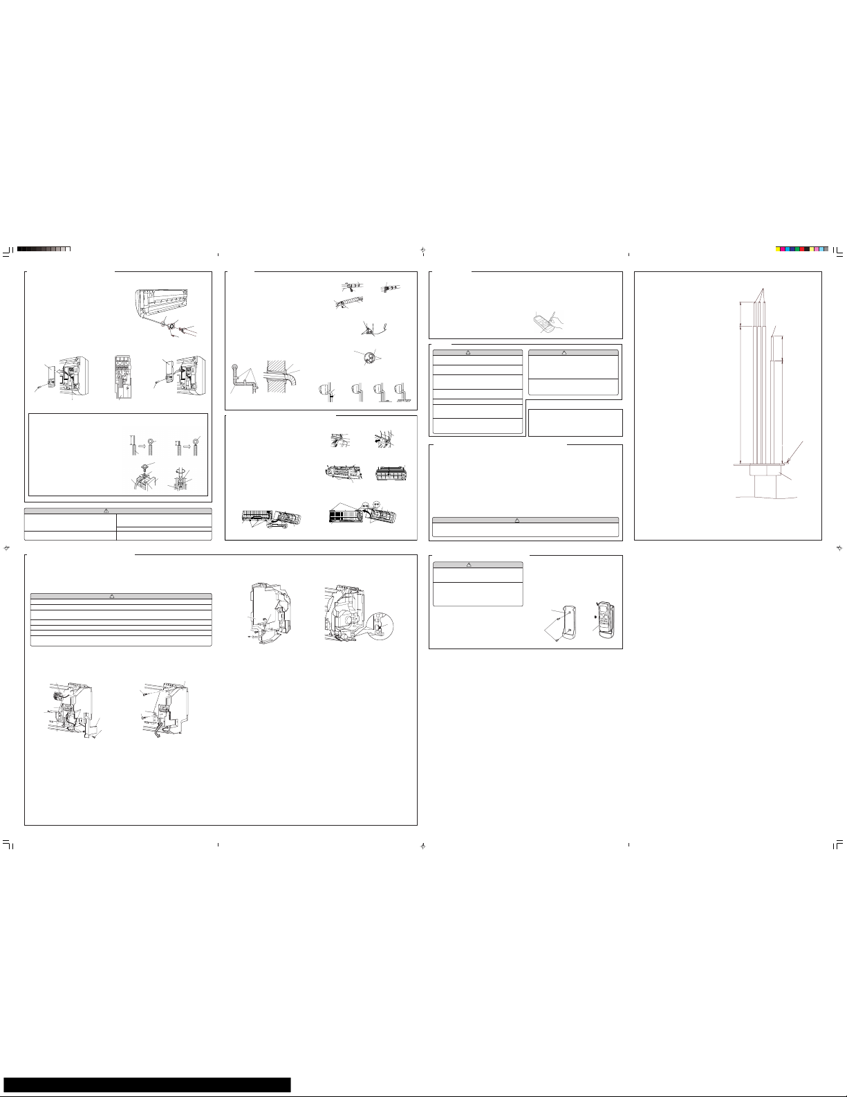
Wave
FINISHING
(1) Insulate between pipes.
● For rear, right, and bottom piping, overlap the connection pipe
heat insulation and indoor unit pipe heat insulation and bind
them with vinyl tape so that there is no gap.
● For left and left rear piping, butt the connection pipe heat insula-
tion and indoor unit pipe heat insulation together and bind them
with and vinyl tape so that there is no gap.
● For left and left rear piping, wrap the area which accommodates
the rear piping housing section with cloth tape.
● For left and left rear piping, bind the connection cord to the top
of the pipe with vinyl tape.
● For left and left rear piping, bundle the piping and drain hose
together by wrapping them with cloth tape over the range within
which they fit into the rear piping housing section.
(2) Temporarily fasten the connection cord along the connection pipe
with vinyl tape. (Wrap to about 1/3 the width of the tape from the
bottom of the pipe so that water does not enter.)
(3) Fasten the connection pipe to the outside wall with a saddle, etc.
(4) Fill the gap between the outside wall pipe hole and the pipe with
sealer so that rain water and wind cannot blow in.
(5) Fasten the drain hose to the outside wall, etc.
Fig. 16
Pipe
(Saddle)
(Outside wall cap)
(Sealer putty)
(Outdoors)
Fig. 15
Drain hose
GOOD
BAD
BAD BAD
Lifted up
Saddle
End in water
Wall
FRONT PANEL REMOVAL AND INSTALLATION
Check the following:
View from indoors
CUSTOMER GUIDANCE
WARNING
(1) The rated voltage of this product is 208/230 V AC
60 Hz.
(2) Before turning on the power, check if the voltage
is within the 208 V-10% to 230V+10% range.
(3) Always use a special branch circuit and install a
special receptacle to supply power to the room
air conditioner.
(4) Use a circuit breaker and receptacle matched to
the capacity of the air conditioner.
(5) Do not extend the power cord.
(6) Perform wiring work in accordance with stand-
ards so that the air conditioner can be operated
safely and positively.
(7) Install a leakage circuit breaker in accordance with
the related laws and regulations and electric com-
pany standards.
CAUTION
(1) The power source capacity must be the sum of
the air conditioner current and the current of other
electrical appliances. When the current contracted
capacity is insufficient, change the contracted capacity.
(2) When the voltage is low and the air conditioner is
difficult to start, contact the power company the
voltage raised.
Explain the following to the customer in accordance with the operating manual:
(1) Starting and stopping method, operation switching, temperature
adjustment, timer, air flow switching, and other remote control unit
operations.
(2) Air filter removal and cleaning, and how to use the air louvers.
(3) Give the operating and installation manuals to the customer.
POWER
(1) Match the terminal block numbers and connection
cord colors with those of the outdoor unit.
Erroneous wiring may cause burning of the electric parts.
(2) Connect the connection cords firmly to the terminal
block. Imperfect installation may cause a fire.
CAUTION
(3) Always fasten the outside covering of the connection
cord with the cord clamp. (If the insulator is chafed,
electric leakage may occur.)
(4) Securely earth the power cord plug.
(5) Do not use the earth screw for an external connector.
Only use for interconnection between two units.
ELECTRICAL WIRING (INDOOR UNIT)
HOW TO THE INSTALL THE INTER-UNIT WIRE HARNESS
1. Remove the screws, then remove the conduit holder.
2. Fasten the inter-unit wire harness to the conduit holder using the lock nut.
IMPORTANT: Refer to Fig. 19 about the length of inter-unit wire harness.
3. Use the screws to install the conduit holder with which Inter-unit wire harness is included.
4. Remove the screws, then remove the cord clamp.
5. Connect inter-unit wire harness to the terminal.
Refer to the wiring diagram.
6. Use the screws to install the cord clamp.
Connection cord
Screw
Connection cord
Screw
Cord clamp
A. For solid core wiring (or F-cable)
(1) Cut the wire end with a wire cutter or wire-cutting pliers, then strip
the insulation to about 15/16" (25 mm) to expose the solid wire.
(2) Using a screwdriver, remove the terminal screw(s) on the terminal
board.
(3) Using pliers, bend the solid wire to form a loop suitable for the termi-
nal screw.
(4) Shape the loop wire properly, place it on the terminal board and
tighten securely with the terminal screw using a screwdriver.
B. For strand wiring
(1) Cut the wire end with a wire cutter or wire-cutting pliers, then strip
the insulation to about 3/8" (10 mm) to expose the strand wiring.
(2) Using a screwdriver, remove the terminal screw(s) on the terminal
board.
(3) Using a round terminal fastener or pliers, securely clamp a round
terminal to each stripped wire end.
(4) Position the round terminal wire, and replace and tighten the termi-
nal screw using a screwdriver.
A. Solid wire
Strip 15/16" (25 mm)
Insulation
Loop
B. Strand wire
Strip 3/8" (10 mm)
Round
terminal
Wire
Screw with
special washer
Round
terminal
Terminal
board
Terminal block
Wire
Screw with
special washer
Round
terminal
HOW TO CONNECT WIRING TO THE TERMINALS
TEST RUNNING
The method of adjusting inter-unit wire harness
To connect inter-unit wire harness to the terminal correctly, please
refer to Fig. 19 to adjust the length of the part of Inter-unit Wire
harness ahead from conduit holder.
WIRED REMOTE CONTROL UNIT (OPTIONAL)
BEFORE INSTALL WIRED REMOTE CONTROL UNIT
• The wired remote control unit is an option. It isn't included in main body of air-conditioner.
• When you use wired remote control unit, some functions may not be used.
• please use the recommended wired remote control unit.
(Before installing, Please read the FEATURES AND FUNCTIONS section of OPERATING MANUAL to confirm the
concerned contents.)
CAUTION
(1) Before installing, be sure to disconnect all power supply.
(2) Don't touch the heat exchanger.
(3) During installing or removing operation, be sure not to have wire catched by parts or draw it hard. Or it
may result troubles to the air-conditioner.
(4) Avoid place in direct sunlight.
(5) Select place that will not be affected by the heat from a stove, etc.
(6) Insure the length of wire is not over the recommended maxuim length.
(7) Before setting up the wired remote control unit, please confirm whether air-conditioner can receive the
signal.
1. FRONT PANEL AND CONTROL UNIT REMOVAL
(1) Refer to " FRONT PANEL REMOBAL AND INSTALLATION " to remove the front panel.
(2) Remove screws of the heat exchanger, ang then remove grounding wire.
(3) Remove 2 thermistor.
(4) Remove screw, then remove the connector cover and connector.
(5) Remove screw, then remove the control unit.
CIRCUIT BOARD
SCREW
CONNECTOR
TO RENOTE
CONNTROL UNIT
CUT
2. Connecting to control unit of wire
(1) Connect the wire of wired remote control unit to the board of Control unit.
(2) Use wire clamper and screws to fasten wire.
(3) Cut off part of the control unit and thread wire through.
3. FRONT PANEL AND CONTROL UNIT INSTALLATION
Install Front panel and Control unit by the reverse procedures as stated in "1. FRONT PANEL AND CONTROL UNIT REMOVAL".
Fig. 14
5-1/2" (140mm) 15/16" (25mm)
15/16" (25mm)
4-3/16" (105mm)
(1:1)
14AWG
EARTH WIRE
CONDUIT PLATE
CONDUIT CONNECTOR
Fig. 19
Fig. 13
Fig. 12
Lock nut
Conduit Holder
Conduit Connector
Screw
CLAMPER
THE INTAKE GRILLE REMOVAL
(1) Open the intake grille.
(2) Pull down the knob.
(3) Lift the intake grille upward, until the axle at the top of the intake
grille is removed.
THE INTAKE GRILLE INSTALLATION
(1) The fixing axle of the intake grille is installed on the Panel.
(2) Lay down the intake grille.
THE FRONT PANEL REMOVAL
(1) Remove intake grille (Reference the intake grille removal.)
(2) Remove four screws.
(3) The thumb is hung on the lower part as shown in the figure, and it
pulls to the front, pushing [-] mark , and bottom hooks (two position) is removed from wall hook bracket.
(4) The front panel bottom is pulled to the front, and bottom hooks is
removed indoor unit.
(5) The front panel is pulled to the front, raising the upper surface,
and a front panel is removed.
THE FRONT PANEL INSTALLATION
(1) Firstly, fit the lower part of the front panel, and insert top and bot-
tom hooks. (Three top sides, six bottom sides)
(2) Four screws is attached.
(3) The intake grille is attached.
Bottom hole
(six position)
Front panel
Indoor unit
Bottom hooks
(six position)
Fig. 17
Front panel
Bearing
Mounting shaft
Intake grille
Intake grille
Knob
Top holes (two sides)
Top hole (center)
Top hook (center)
Front panel
Top hooks
(two sides)
Indoor unit
Wall hook bracket
Front panel
Push
[-] mark
Push
Front panel
Screws
(4 position)
Indoor unit pipe (heat insulation)
Connection pipe
(heat insulation)
Vinyl tape
Seal A
Butt connection pipe (heat
insulation) against the indoor
unit pipe (heat insulation)
and wrap with seal A so that
there is no gap.
Pipe
Drain hose
Cloth tape
Wrap with
cloth tape
Left piping
Connection cord
Pipe
Drain hose
For connection from the left rear
Connection cord
Drain hose
Wall pipe
Connection pipe
● Perform test operation and check items 1 and 2 below.
● For the test operation method, refer to the operating manual.
● The outdoor unit, may not operate, depending on the room temperature. In this case, press the test run button on the remote control unit
while the air conditioner is running, (Point the transmitter section of the remote control unit toward the air conditioner and press the test run
button with the tip of a ball-point pen, etc.)
● To end test operation, press the remote control unit START/STOP button.
(When the air conditioner is run by pressing the test run button, the OPERATION indicator lamp and TIMER indicator lamp will simultaneously
flash slowly.)
1. INDOOR UNIT
(1) Is operation of each button on the remote control unit normal?
(2) Does each lamp light normally?
(3) Do the air flow-direction louver operate normally?
(4) Is the drain normal?
2. OUTDOOR UNIT
(1) Is there any abnormal noise and vibration during operation?
(2) Will noise, wind, or drain water from the unit disturb the neighbors?
(3) Is there any gas leakage?
Fig. 18
Transmitter section
Test run button
REMOTE CONTROL UNIT INSTALLATION
CAUTION
(1) Check that the indoor unit correctly receives the
signal from the remote control unit, then install
the remote control unit holder.
(2) Select the remote control unit holder selection
site by paying careful attention to the following:
Avoid places in direct sunlight.
Select a place that will not be affected by the heat
from a stove, etc.
1. REMOTE CONTROL UNIT HOLDER INSTALLATION
• Install the remote control unit with a distance of 23 ft(7
m) between the remote control unit and the photocell
as the criteria. However, when installing the remote control unit, check that it operates positively.
• Install the remote control unit holder to a wall, pillar,
etc. with the tapping screw (Fig.20).
Remote control unit
holder fixing
Remote control
unit holder
Tapping
screw
(small)
Remote control
unit mounting
Remote
control unit
2 Push
1 Set
Fig. 20
PUMP DOWN OPERATION (FORCED COOLING OPERATION)
To avoid discharging refrigerant into the atmosphere at the time of relocation or disposal, recover refrigerant by doing the cooling operation or
forced cooling operation according to the following procedure. (When the cooling operation cannot start in winter, and so on, start the forced
cooling operation.)
(1) Do the air purging of the charge hose by connecting the charging hose of gauge manifold to the charging port of 3 way valve and opening the
low-pressure valve slightly.
(2) Close the valve stem of 2 way valve completely.
(3) Start the cooling operation or following forced cooling operation.
When using the remote control unit
Press the TEST RUN button after starting the cooling operation by the remote control unit.
The operation indicator lamp and timer indicator lamp will begin to flash simultaneously during test run.
When using the MANUAL AUTO button of the indoor unit (The remote control unit is lost, and so on.)
Keep on pressing the MANUAL AUTO button of the indoor unit for more than 10 seconds.
(The forced cooling operation cannot start if the MANUAL AUTO button is not kept on pressing for more than 10 seconds.)
(4) Close the valve stem of 3 way valve when the reading on the compound pressure gage becomes 0.05~0 MPa (0.5~0 kg/cm
2
).
(5) Stop the operation.
• Press the START/STOP button of the remote control unit to stop the operation.
• Press the MANUAL AUTO button when stopping the operation from indoor unit side.
(It is not necessary to press on keeping for more than 10 seconds.)
CAUTION
During the pump-down operation, make sure that the compressor is turned off before you remove the refrigerant piping.
Do not remove the connection pipe while the compressor is in operation with 2 way or 3 way valve open. This may cause abnormal
pressure in the refrigeration cycle that leads to breakage and even injury.
THERMISTOR HOLDER
CONNECTOR
CONNECTOR COVER
SCREW
EARTH WIRE
SCREW
THERMISTOR
CONTROL UNIT
SCREW
SCREW
Cord clamp
Page 81

1116, Suenaga, Takatsu-ku, Kawasaki 213-8502, Japan
GS01012006
JAN 2006 Printed in Japan
 Loading...