

Page 1
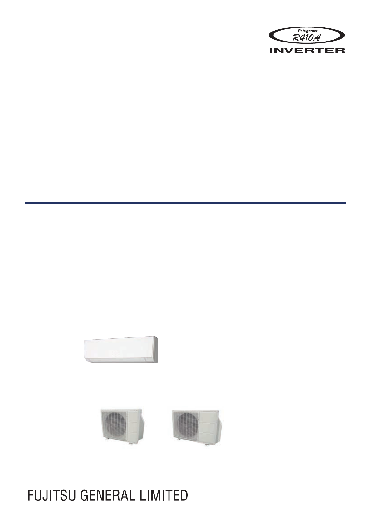
AIR CONDITIONER
Wall Mounted type
DESIGN & TECHNICAL MANUAL
INDOOR
OUTDOOR
ASU9RLF1
ASU12RLF1
AOU12RLFW1AOU9RLFW1
Page 2

1. INDOOR UNIT
WALL MOUNTED TYPE :
ASU9RLF1
ASU12RLF1
DTR_AS090E_01
2013.11.22
Page 3

CONTENTS
WALL MOUNTED TYPE
ASU9-12RLF1
WALL MOUNTED TYPE
ASU9-12RLF1
1. INDOOR UNIT
1. FEATURES
2. WIRELESS REMOTE CONTROLLER
3. SPECIFICATIONS
4. DIMENSIONS
5. WIRING DIAGRAMS
6. CAPACITY TABLE
6-1. COOLING CAPACITY
6-2. HEATING CAPACITY
7. FAN PERFORMANCE
7-1. AIR VELOCITY DISTRIBUTION
7-2. AIR FLOW
.............................................................................................................. 01 - 01
............................................... 01 - 03
.............................................................................................. 01 - 05
........................................................................................................ 01 - 06
........................................................................................ 01 - 08
............................................................................................ 01 - 09
...................................................................................... 01 - 09
....................................................................................... 01 - 10
.....................................................................................01 - 11
......................................................................01 - 11
.......................................................................................................... 01 - 12
8. OPERATION NOISE (SOUND PRESSURE)
8-1. NOISE LEVEL CURVE
.................................................................................... 01 - 13
................................. 01 - 13
8-2. SOUND LEVEL CHECK POINT
..................................................................... 01 - 14
9. ELECTRICAL CHARACTERISTICS
10. SAFETY DEVICES
11. EXTERNAL INPUT & OUTPUT
11-1. EXTERNAL INPUT
11-2. EXTERNAL OUTPUT
12. FUNCTION SETTINGS
13. OPTIONAL PARTS
13-1. CONTROLLERS
13-2. OTHERS
............................................................................................................. 01 - 26
............................................................................................ 01 - 16
............................................................... 01 - 17
........................................................................................... 01 - 17
....................................................................................... 01 - 19
.................................................................................. 01 - 21
........................................................................................... 01 - 26
............................................................................................... 01 - 26
................................................... 01 - 15
Page 4
FEATURES1.
1/4 3/16
in.
( )
Ø3/16in.
(Ø5mm)
“MIN. HEAT”
Button ON
Indoor unit
operation START
68
°F
(20°C)
50
°F
(10°C)
MODELS
ASU9RLF1 / AOU9RLFW1
WALL MOUNTED TYPE
ASU9-12RLF1
ASU12RLF1 / AOU12RLFW1
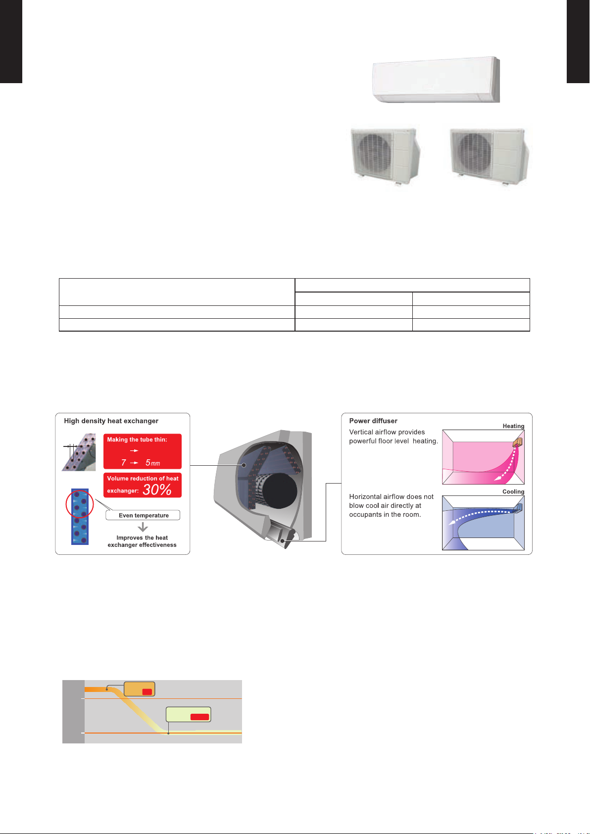
FEATURES
Energy efciency class
z
Seasonal Energy Efciency Ratio (SEER) 23.0 22.0
Heating Seasonal Performance Factor (HSPF) 11. 0 11. 0
AOU12RLFW1AOU9RLFW1
MODEL
ASU9RLF1 ASU12R LF1
WALL MOUNTED TYPE
ASU9-12RLF1
MEASUREMENT CONDITIONS
ANSI/ASHRAE STANDARD 37-1988
High efcient compact design
z
MIN. HEAT Operation
z
*Only available with Wireless RC.
More comfortable airow
z
The room temperature can be set to go no lower than 50°F (10°C),
thus ensuring that the room does not get too cold when not occupied
Caution)
When the room temperature is higher than 50°F (10°C), “ •
temperature at 50°F (10°C) when the temperature drops below 50°F (10°C).
MIN. HEAT
When “ •
” operation stops, the room set temperature quickly returns to the preset temperature.
MIN. HEAT
” operation will not start. Operation starts and maintains the room
- (01 - 01) -
Page 5
WALL MOUNTED TYPE
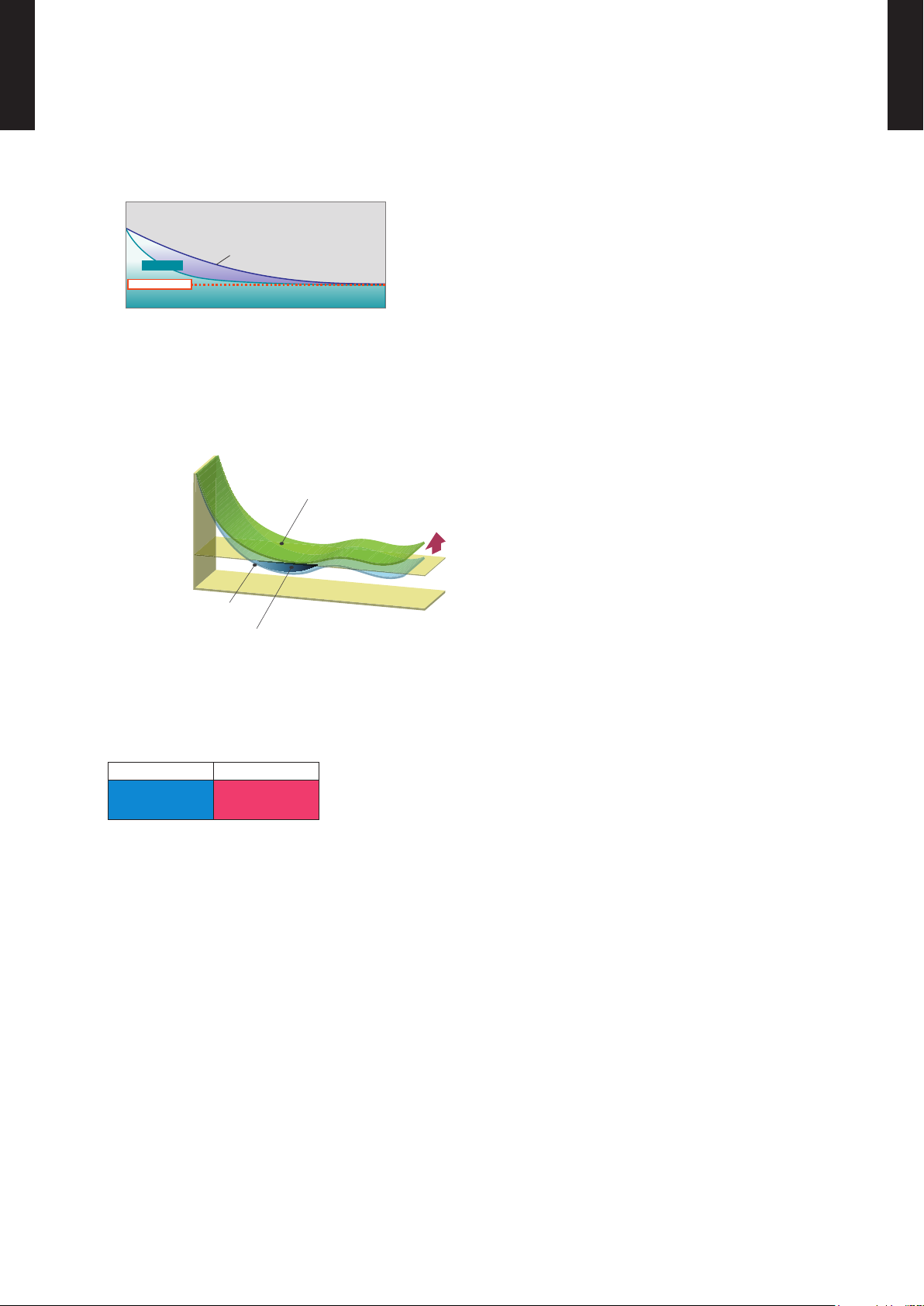
Powerful
Setting temp.
Normal mode
Time
Temperature
Temp.
Economy operation
Shift
setting
temp
Control maximum current
Normal operation
Time
Set temperature
ASU9-12RLF1
Powerful operation
z
WALL MOUNTED TYPE
ASU9-12RLF1
20 minutes continuous operation by maximum airow and maximum compressor speed is
possible. Rapid cooling and heating makes the room comfortable quickly.
Economy operation
z
Example : Cooling operation
• Economy operation is energy saving, as the set temperature of indoor unit is shifted by 2°F (1°C)
and the maximum electric value of the outdoor unit is suppressed.
Low outdoor air temperature correspondence
z
Corresponds to cooling operation at 14°F (-10°C) outdoor air temperature
Corresponds to heating operation at 5°F (-15°C) outdoor air temperature
Cooling Heating
14 to 115°F
(-10 to 46°C)
5 to 75 °F
(-15 to 24°C)
- (01 - 02) -
Page 6
WIRELESS REMOTE CONTROLLER2.
60min.
2°F (1°C)
4°F (2°C)
Timer setting
30min.
60min.
90min.
8°F
(4°C)
Timer setting
6°F
(3°C)
4°F
(2°C)
2°F
(1°C)
A B C D
A B
C
D
Mixed-up
I.U. I.U. I.U. I.U.
I.U. I.U. I.U. I.U.
After code change
REG1U
FEATURES
WALL MOUNTED TYPE
ASU9-12RLF1
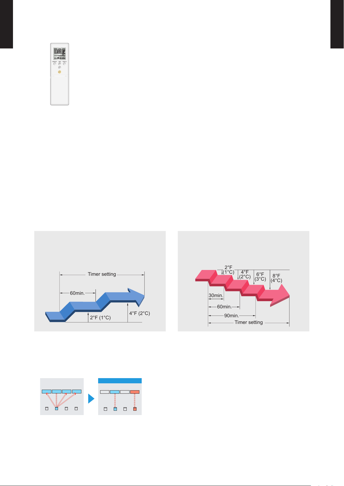
Simple function setting
z
4 mode timer setup available (ON / OFF / PROGRAM / SLEEP).
Easy operation.
Easy to change custom code (max. 4 custom codes) by button operation.
WALL MOUNTED TYPE
ASU9-12RLF1
Setting of the air conditioner selection function is performed by remote controller.
Built-in timers
z
Select from four different timer programs (On / Off / Program / Sleep).
Program timer
z
The program timer operates the on and off timer once within a 24-hour period.
Sleep timer
z
The sleep timer function automatically corrects the temperature thermostat setting according to
the timer setting to prevent excessive cooling and heating while sleeping.
Cooling operation/dry operation
When the sleep timer is set, the set temperature
automatically rises 2°F (1°C) every hour. The set
temperature can rise up to a maximum of 4°F (2°C).
Simple function setting
z
Heating operation
When the sleep timer is set, the set temperature
automatically drops 2°F (1°C) every 30 minutes. The
set temperature can drop to a maximum of 8°F (4°C).
Setting of the air conditioner selection function is performed by remote controller.
Switching remote controller custom code
z
Code selector switch eliminates unit
•
being wrongly switched.
(Up to 4 custom codes can be set.)
*I.U.=Indoor unit
To change the temperature unit
z
Easy to change the temperature unit (
°F ↔ °C) by button operation.
- (01 - 03) -
Page 7
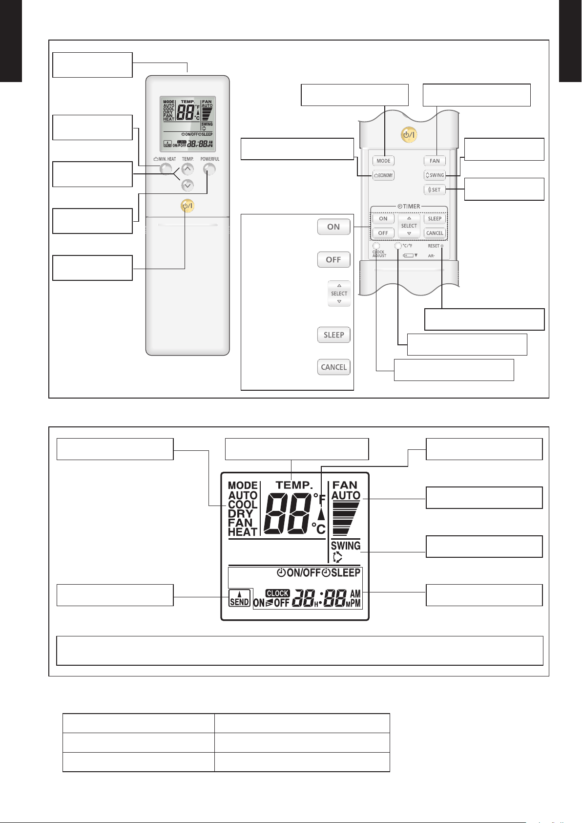
FUNCTIONS
REG1U
REG1U
Signal
WALL MOUNTED TYPE
ASU9-12RLF1
transmitter
WALL MOUNTED TYPE
ASU9-12RLF1
MIN. HEAT
button
TEMP.
button
POWERFUL
button
Start/Stop
button
ECONOMY button
TIMER ON button
TIMER OFF button
TIMER SELECT button
TIMER SLEEP button
TIMER CANCEL button
MODE button
CLOCK ADJUST button
FAN button
SWING button
SET button
RESET button
°C / °F switching button
Display panel
Mode indicator
Temperature indicator
Send indicator
To facilitate explanation, the accompanying illustration has been drawn to show all possible indicators; in actual operation,
however, the display will only show those indicators appropriate to the current operation.
SPECIFICATION
Transmit indicator
Fan Speed indicator
Swing indicator
Clock & Timer
indicator
DIMENSIONS [H × W × D]: in. (mm) 8-1/16 (205) × 2-3/8 (61) × 11/16 (17)
WEIGHT oz. (g) 4.3 (122)
ACCESSORY Holder
- (01 - 04) -
NOTE: Some button operations may
not be available for all units
or systems.
For details, refer to the
operation manual.
Page 8
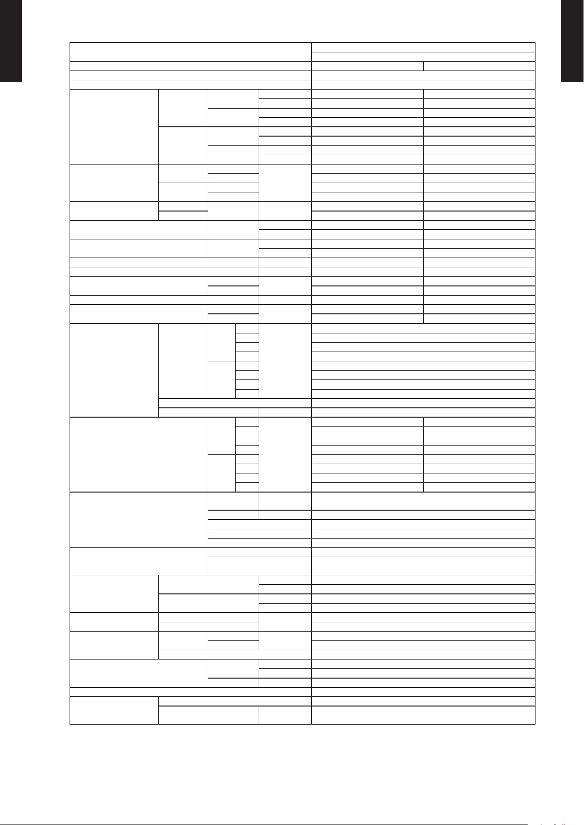
SPECIFICATIONS3.
Typ e
Model name ASU9 RLF1 ASU12R LF1
WALL MOUNTED TYPE
ASU9-12RLF1
Power source 208/230V~60HZ
Available voltage range 187-253V~60HZ
Cooling
Capacity
Heating
Input power
Current
EER Cooling
COP Heating
SEER Cooling BTU/hW 23.0 22.0
HSPF Heating BTU/hW 11. 0 11.0
POWER FACTOR
Moisture removal pints/h(l/h) 2.7 5(1. 3) 3.80(1.8)
Maximum operating current *
Fan
Sound pressure level
Heat exchanger type
Enclosure
Dimensions
(H×W×D)
Weight
Connection pipe
Operation range
Remote controller type Wireless
Drain pipe
Cooling
Heating
Cooling
Heating 4.2 5.9
Airow rate
Typ e×Q' ty Cross ow fan×1
Motor output W 30
Net
Gross
Net
Gross 24(10. 5)
Size
Method Flare
Material PP + LLDPE
Size
Rated
Min-Max
Rated
Min-Max
Rated
Min - Max 0.25 - 1.27 0.25 - 1.40
Rated 0.89 1.28
Min - Max 0.25 - 1.60 0.25 - 1.99
Rated A
Cooling
Heating 92 94
Cooling
Heating 7. 5 9.0
High
Med 376(640)
Cooling
Low 282(4 80)
Quiet 182(310)
High 441(75 0)
Med 376(640)
Heating
Low 306(520)
Quiet 194(33 0)
High
Med 40 40
Cooling
Low 32 32
Quiet 21 21
High 43 43
Med 38 38
Heating
Low 33 33
Quiet 22 22
Dimensions
(H×W×D)
Fin pitch FPI Main:23 Sub:18
Rows×Stages Main:2×20 Sub:1×4
Pipe type Copper
Fin type Aluminum
Material Polystyrene
Color
Liquid
Gas Ø3/8(Ø9.52)
Cooling
Heating °F(° C) 88(30) or less
kW 2.637 3. 516
BTU/h 9000 12000
kW 0.50-3.20 0.90-3.90
BTU/h 1700-10900 3100-13300
kW 3.516 4.689
BTU/h 12000 16000
kW 0.50-4.40 0.90-5.60
BTU/h 1700-15000 3100-19100
kW
kW/kW 4.05 3.66
BTU/hW 13. 8 12.5
kW/kW 3.95 3.66
BTU/hW 13.50 12.50
%
A
CFM
(m3/h)
dB(A)
in. (mm)
mm 268 x 840 x 203
in. 10-9/16 x 33 -1/16 x 8
mm 270 x 884 x 336
in. 10-5/8 x 34-13/16 x 13-1/4
lb.(kg)
in. (mm)
°F(° C) 64 to 90(18 to 32)
%RH 80 or less
mm
(Reference in.)
0.65 0.96
3.2 4.4
88 95
6.0 6.5
43 43
Main: 12-5/8 x 24-13/16 x 13/16 (320×630×20)
Sub: 3-5/16 x 24-13/16 x 1/2 (84×630×13.3)
Approximate color of MUNSELL N9. 25/
WALL MOUNTED
INVERTER HEAT PUMP
441(7 50)
White
19(8.5)
Ø1/4(Ø6.35)
Ø 9/16 (13.8) (I.D.)
Ø5/8 to Ø11/16 (15.8 to 16.7) (O.D.)
WALL MOUNTED TYPE
ASU9-12RLF1
Note:
●Specications are based on the following conditions.
Cooling:Indoor temperature of 80°F(26.67°C)DB/67°F(19.44°C)WB,and outdoor temperature of 95°F(35°C)DB/75°F(23.9°C)WB.
Heating:Indoor temperature of 70°F(21.11°C)DB/59°F(15°C)WB,and outdoor temperature of 47°F(8.33°C)DB/43°F(6.11°C)WB.
Pipe length:24ft.(7.5m),Height difference:0ft. (0m) (Outdoor unit-Indoor unit)
●The protective function might work when using it in environment out of the temperature range mentioned above.
*: The maximum current is the ma ximum value when operated within the operation range.
- (01 - 05) -
Page 9
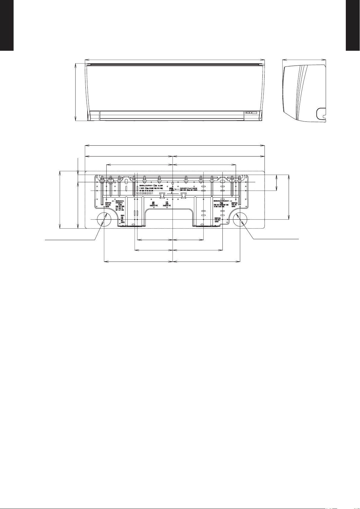
DIMENSIONS4.
33-1/16 (840) 8 (203)
(33-1/16 (840))
16-1/8 (410) 16-15/16 (430)
(10-9/16 (268))
1-5/16 (34) 8-1/2 (216)
ø2-9/16 (65) for pipe inlet
12-3/16 (310) 11-5/8 (295)
6-1/2 (165)
7 (178)
12-5/8 (321)
5-11/16 (144)
8-1/4 (209)
2-15/16
(74)
9-3/16 (233)
12-3/8 (315)
ø2-9/16 (65) for pipe inlet
10-9/16 (268)
MODELS : ASU9RLF1, ASU12RLF1
WALL MOUNTED TYPE
ASU9-12RLF1
Unit : in. (mm)
WALL MOUNTED TYPE
ASU9-12RLF1
- (01 - 06) -
Page 10
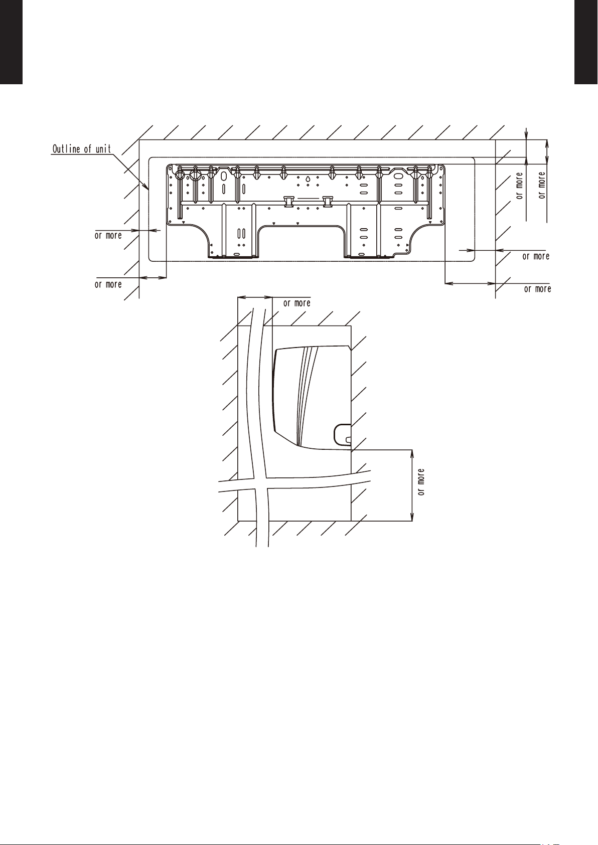
WALL MOUNTED TYPE
1 (25)
3 (70)
60 (1500)
6 (130)
3 (52)
2 (45)
3 (63)
71 (1800)
ASU9-12RLF1
INSTALLATION PLACE
WALL MOUNTED TYPE
ASU9-12RLF1
Unit : in. (mm)
- (01 - 07) -
Page 11
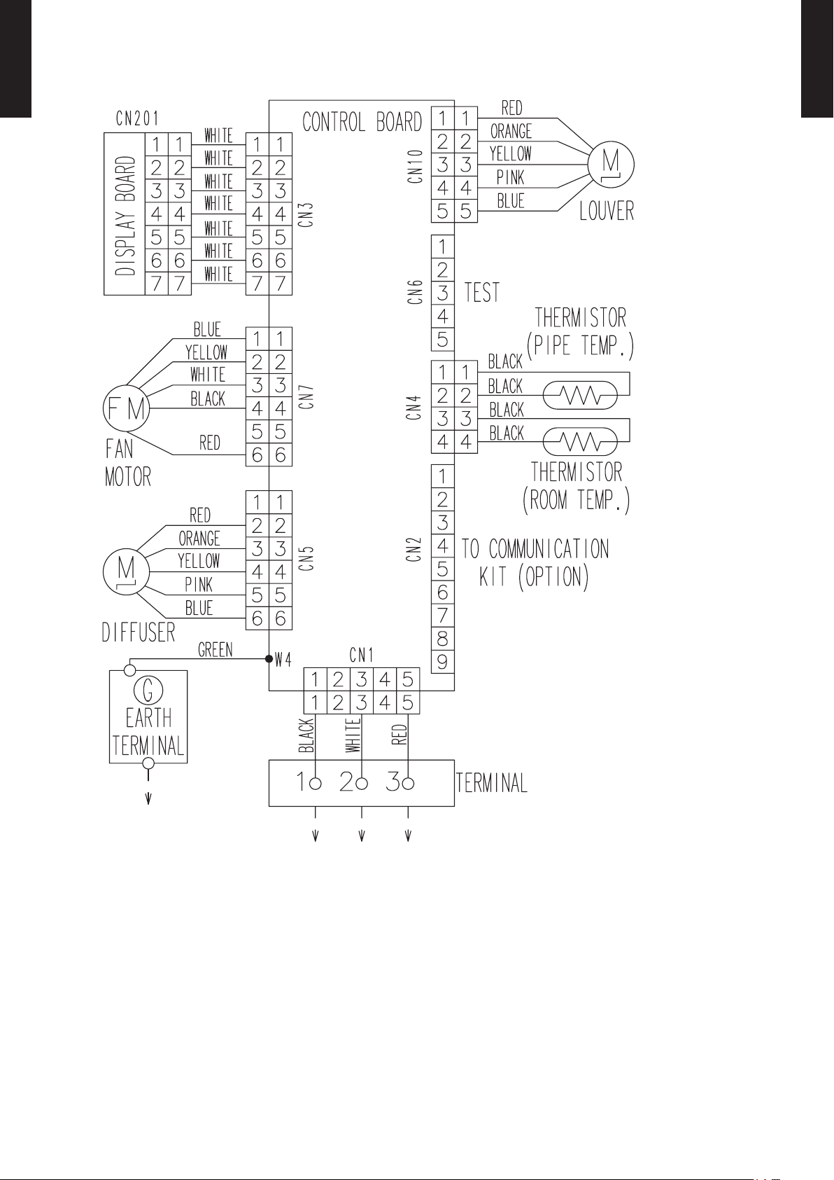
WIRING DIAGRAMS5.
MODELS : ASU9RLF1, ASU12RLF1
WALL MOUNTED TYPE
ASU9-12RLF1
WALL MOUNTED TYPE
ASU9-12RLF1
- (01 - 08) -
Page 12
CAPACITY TABLE6.
COOLING CAPACITY6-1.
WALL MOUNTED TYPE
ASU9-12RLF1
MODEL : ASU9RLF1
AFR 441
°FDB 64 70 75 80 85 90
°FWB 54 60 63 67 71 73
°FDB TC SHC IP TC SHC IP TC SHC IP TC SHC IP TC SHC IP TC SHC IP
59 6.41 4.83 0.22 7.14 4.86 0.23 7.87 5.30 0.23 8.11 5.72 0.23 8.60 5.70 0.23 9.08 6.07 0.24
67 8.53 5.30 0.44 9.51 5.33 0.45 10.48 5.81 0.46 10.80 6.28 0.46 11.45 6.25 0.46 12.10 6.66 0.47
77 8.03 5.30 0.51 8.95 5.34 0.52 9.86 5.82 0.52 10.17 6.29 0.53 10.78 6.26 0.53 11.39 6.67 0.54
87 7.53 5.11 0.57 8.38 5.14 0.58 9.24 5.60 0.59 9.53 6.05 0.59 10.10 6.03 0.60 10.67 6.42 0.61
95 7.11 4.98 0.63 7.92 5.01 0.64 8.73 5.46 0.65 9.00 5.90 0.65 9.54 5.88 0.66 10.08 6.26 0.66
104 5.91 4.64 0.51 6.59 4.67 0.52 7.26 5.09 0.53 7.48 5.50 0.53 7.93 5.48 0.54 8.38 5.83 0.54
Outdoor temperature
115 4.18 3.28 0.39 4.66 3.30 0.39 5.13 3.60 0.40 5.29 3.89 0.40 5.61 3.87 0.41 5.93 4.13 0.41
AF R : Air ow ra te (CFM)
TC : Total c apacit y (kBTU)
SH C : Sensib le Heat ca pacit y (kBTU)
IP : I nput Power ( kW)
AFR 12.5
°CDB 17.8 21.1 23.9 26.7 29.4 32.2
°CWB 12.2 15.6 17.7 19.4 21.7 22.8
°CDB TC SHC IP TC SHC IP TC SHC IP TC SHC IP TC SHC IP TC SHC IP
15.0 1.88 1.42 0.22 2.09 1.42 0.23 2.31 1.55 0.23 2.38 1.68 0.23 2.52 1.67 0.23 2.66 1.78 0.24
19.4 2.50 1.55 0.44 2.79 1.56 0.45 3.07 1.70 0.46 3.17 1.84 0.46 3.36 1.83 0.46 3.55 1.95 0.47
25.0 2.35 1.55 0.51 2.62 1.56 0.52 2.89 1.71 0.52 2.98 1.84 0.53 3.16 1.83 0.53 3.34 1.95 0.54
30.6 2.21 1.50 0.57 2.46 1.51 0.58 2.71 1.64 0.59 2.79 1.77 0.59 2.96 1.77 0.60 3.13 1.88 0.61
35.0 2.08 1.46 0.63 2.32 1.47 0.64 2.56 1.60 0.65 2.64 1.73 0.65 2.80 1.72 0.66 2.95 1.83 0.66
40.0 1.73 1.36 0.51 1.93 1.37 0.52 2.13 1.49 0.53 2.19 1.61 0.53 2.33 1.60 0.54 2.46 1.71 0.54
Outdoor temperature
46.1 1.23 0.96 0.39 1.37 0.97 0.39 1.50 1.06 0.40 1.55 1.14 0.40 1.64 1.13 0.41 1.74 1.21 0.41
AF R : Air ow ra te (m3/min)
TC : Total c apacit y (kW)
SH C : Sensib le Heat ca pacit y (kW)
IP : I nput Power ( kW)
Indoor temperature
Indoor temperature
WALL MOUNTED TYPE
ASU9-12RLF1
MODEL : ASU12RLF1
AFR 441
°FDB 64 70 75 80 85 90
°FWB 54 60 63 67 71 73
°FDB TC SHC IP TC SHC IP TC SHC IP TC SHC IP TC SHC IP TC SHC IP
59 8.3 6.34 0.40 9.3 6.38 0.41 10.2 6.96 0.42 10.5 7.51 0.42 11.1 7.48 0.42 11.8 7.97 0.43
67 11.4 7.47 0.65 12.7 7.52 0.66 14.0 8.20 0.67 14.5 8.85 0.68 15.3 8.82 0.68 16.2 9.39 0.69
77 10.8 7.14 0.75 12.0 7.18 0.76 13.3 7.83 0.77 13.7 8.46 0.77 14.5 8.42 0.78 15.3 8.97 0.79
87 10.1 6.99 0.85 11.2 7.03 0.86 12.4 7.67 0.87 12.8 8.28 0.88 13.5 8.25 0.88 14.3 8.78 0.89
95 9.5 6.67 0.93 10.6 6.71 0.94 11.6 7.32 0.96 12.0 7.91 0.96 12.7 7.87 0.97 13.4 8.39 0.98
104 8.0 6.35 0.87 9.0 6.39 0.89 9.9 6.97 0.90 10.2 7.52 0.91 10.8 7.49 0.92 11.4 7.98 0.92
Outdoor temperature
115 5.6 5.15 0.69 6.3 5.18 0.70 6.9 5.65 0.71 7.2 6.10 0.71 7.6 6.07 0.72 8.0 6.47 0.73
AF R : Air ow ra te (CFM)
TC : Total c apacit y (kBTU)
SH C : Sensib le Heat ca pacit y (kBTU)
IP : I nput Power ( kW)
AFR 12.5
°CDB 17.8 21.1 23.9 26.7 29.4 32.2
°CWB 12.2 15.6 17.7 19.4 21.7 22.8
°CDB TC SHC IP TC SHC IP TC SHC IP TC SHC IP TC SHC IP TC SHC IP
15.0 2.43 1.86 0.40 2.71 1.87 0.41 2.99 2.04 0.42 3.08 2.20 0.42 3.27 2.19 0.42 3.45 2.34 0.43
19.4 3.35 2.19 0.65 3.73 2.20 0.66 4.12 2.40 0.67 4.24 2.59 0.68 4.50 2.58 0.68 4.75 2.75 0.69
25.0 3.17 2.09 0.75 3.53 2.10 0.76 3.89 2.30 0.77 4.01 2.48 0.77 4.25 2.47 0.78 4.49 2.63 0.79
30.6 2.96 2.05 0.85 3.30 2.06 0.86 3.63 2.25 0.87 3.75 2.43 0.88 3.97 2.42 0.88 4.19 2.57 0.89
35.0 2.78 1.96 0.93 3.10 1.97 0.94 3.41 2.15 0.96 3.52 2.32 0.96 3.73 2.31 0.97 3.94 2.46 0.98
40.0 2.36 1.86 0.87 2.63 1.87 0.89 2.90 2.04 0.90 2.99 2.20 0.91 3.16 2.20 0.92 3.34 2.34 0.92
Outdoor temperature
46.1 1.66 1.51 0.69 1.84 1.52 0.70 2.03 1.65 0.71 2.10 1.79 0.71 2.22 1.78 0.72 2.35 1.90 0.73
AF R : Air ow ra te (m3/min)
TC : Total c apacit y (kW)
SH C : Sensib le Heat ca pacit y (kW)
IP : I nput Power ( kW)
Indoor temperature
Indoor temperature
- (01 - 09) -
Page 13
HEATING CAPACITY6-2.
WALL MOUNTED TYPE
ASU9-12RLF1
MODEL : ASU9RLF1
AFR 441
WALL MOUNTED TYPE
ASU9-12RLF1
°FDB 60 65 70 75
°FDB °FWB TC IP TC IP TC IP TC IP
5 3 7.18 0.68 7. 01 0.69 6.84 0.71 6.66 0.72
14 12 8.1 3 0.73 7.94 0.75 7.7 4 0.76 7.55 0.78
23 19 9.10 0 .76 8.88 0.78 8.66 0.79 8.45 0.81
32 28 10.4 8 0.81 10.23 0.8 3 9.98 0.8 4 9.73 0.86
41 37 11.91 0.8 6 11.63 0.88 11.34 0. 90 11.06 0.9 2
47 43 12. 60 0.85 12.30 0.87 12.00 0.89 11.70 0.91
50 47 12.26 0.73 11.97 0.75 11.68 0.76 11.39 0.78
59 50 12.47 0.72 12.18 0.74 11.88 0.75 11.58 0.77
Outdoo r temper ature
68 59 12.82 0.67 12.51 0.68 12.21 0.70 11.90 0.71
75 65 13.3 2 0.67 13.00 0.6 8 12. 68 0.69 12.3 6 0.71
AFR : Air ow ra te (CFM)
TC : Total c apacit y (kBTU)
IP : I nput Power ( kW)
AFR 12 .5
°CDB 15.6 18 .3 21.1 23.9
°CDB °CWB TC IP TC IP TC IP TC IP
-15 2.10 2.10 0.68 2.0 5 0.69 2.0 0 0.71 1.9 5 0.72
-10 2.38 2.38 0.73 2.3 3 0.75 2. 27 0.76 2. 21 0.78
-5 2.67 2 .67 0.76 2 .60 0.78 2 .54 0.79 2.48 0. 81
0 3.07 3.07 0.81 3.00 0.83 2 .93 0.8 4 2 .85 0.8 6
5 3.4 9 3.49 0. 86 3. 41 0.88 3.32 0.90 3.24 0.92
7 3.6 9 3.69 0.85 3.61 0.87 3.52 0 .89 3.4 3 0.91
10 3.59 3. 59 0.73 3.51 0.75 3 .42 0.76 3. 34 0.78
15 3.66 3. 66 0.72 3 .57 0.74 3 .48 0.75 3.40 0.77
Outdoo r temper ature
20 15 3.76 0.67 3.67 0.68 3.5 8 0.70 3.4 9 0.71
24 18 3.9 0 0.67 3.81 0.68 3.72 0.69 3.6 2 0.71
AF R : Air ow ra te (m3/min)
TC : Total c apacit y (kW)
IP : I nput Power ( kW)
Indoor t empera ture
Indoor t empera ture
MODEL : ASU12RLF1
AFR 441
°FDB 60 65 70 75
°FDB °FWB TC IP TC IP TC IP TC IP
5 3 10.71 1.0 9 10.46 1.12 10. 20 1.14 9.9 5 1 .16
14 12 12.04 1.13 11.76 1.15 11.47 1.18 11.18 1.20
23 19 13.35 1.18 13.03 1.20 12.71 1.23 12. 40 1.25
32 28 15.17 1.26 14.80 1.29 14. 44 1.31 14.08 1.34
41 37 16.13 1.2 3 15.75 1.25 15.3 6 1.28 14.98 1.30
47 43 16. 80 1.23 16.40 1. 25 16.00 1.28 15.60 1.31
50 47 17.20 1.23 16.79 1.25 16.38 1.28 15.97 1.30
59 50 16.87 1.1 5 16 .47 1.17 16.07 1.20 15.67 1.22
Outdoo r temper ature
68 59 15.63 0.91 15. 25 0.92 14.8 8 0. 94 14.51 0.9 6
75 65 15.9 4 0.89 15.56 0.91 15.18 0.93 14.8 0 0. 95
AFR : Air ow ra te (CFM)
TC : Total c apacit y (kBTU)
IP : I nput Power ( kW)
AFR 12 .5
°CDB 15.6 18 .3 21.1 23.9
°CDB °CWB TC IP TC IP TC IP TC IP
-15 -16 3.1 4 1.09 3.07 1.12 2.9 9 1.14 2.9 2 1 .16
-10 -11 3.53 1.13 3.45 1.1 5 3.36 1.18 3.28 1. 20
-5 -7 3.91 1.18 3.82 1.20 3.73 1. 23 3.63 1.25
0 -2 4. 44 1.26 4. 34 1.29 4.23 1.31 4.13 1.34
5 3 4.73 1.23 4. 62 1.25 4. 50 1.28 4.39 1.30
7 6 4.92 1.23 4.81 1.25 4. 69 1.28 4.57 1.31
10 8 5.0 4 1.23 4.9 2 1.25 4.8 0 1.28 4.68 1.30
15 10 4.94 1.1 5 4.83 1.17 4.71 1. 20 4.59 1. 22
Outdoo r temper ature
20 15 4.58 0 .91 4.47 0 .92 4.36 0.94 4.2 5 0 .96
24 18 4.67 0.89 4.5 6 0.91 4.4 5 0.93 4.3 4 0.95
AF R : Air ow ra te (m3/min)
TC : Total c apacit y (kW)
IP : I nput Power ( kW)
Indoor t empera ture
Indoor t empera ture
- (01 - 10) -
Page 14
FAN PERFORMANCE7.
7 (2)
3 (1) 2 (0.5)
7 (2)
3 (1)
3 (1)
2 (0.5)
2 (0.5)
7 (2)
3 (1)
2 (0.5)
7 (2)
3 (1)
2 (0.5)
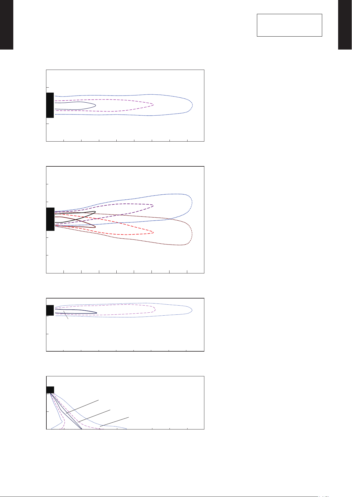
AIR VELOCITY DISTRIBUTION7-1.
WALL MOUNTED TYPE
ASU9-12RLF1
MODELS : ASU9RLF1, ASU12RLF1
(m)
(f t .)
2
7
1
3
0
0
1
3
2
7
0 1 2 3 4 5 6 7 8 9
0 3 7 10 13 16 20 23 26 30
(m)
(f t .)
10
3
7
2
Unit : ft./s (m/s)
Unit : ft./s (m/s)
TOP VIEW
Vertic al air ow direc tion lou ver: Up
Horizo ntal air ow direction l ouver: C enter
(m)
(f t .)
TOP VIEW
Vertic al air ow direc tion lou ver: Up
Horizo ntal air ow direction l ouver: R ight & Left
Conditions:
Fan speed: HIGH
Operation mode: FAN
WALL MOUNTED TYPE
ASU9-12RLF1
3
1
0
0
3
1
7
2
10
3
0 1 2 3 4 5 6 7 8 9
0 3 7 10 13 16 20 23 26 30
(f t .)
(m)
10
3
7
2
3
1
0
0
0 1 2 3 4 5 6 7 8 9
0 3 7 10 13 16 20 23 26 30
(m)
(f t .)
10
3
7
2
Unit : ft./s (m/s)
Unit : ft./s (m/s)
(m)
(f t .)
SIDE VI EW
Vertic al air ow direc tion lou ver: Up
Horizo ntal air ow direction l ouver: C enter
(m)
(f t .)
SIDE VI EW
Vertic al air ow direc tion lou ver: Dow n
Horizo ntal air ow direction l ouver: C enter
3
1
0
0
0 1 2 3 4 5 6 7 8 9
0 3 7 10 13 16 20 23 26 30
- (01 - 11) -
(m)
(f t .)
Page 15

AIR FLOW7-2.
WALL MOUNTED TYPE
ASU9-12RLF1
MODELS : ASU9RLF1, ASU12RLF1
Cooling
z
Number of
Fan speed
rotations
Air ow
(r.p.m.)
3
m
/h 750
WALL MOUNTED TYPE
ASU9-12RLF1
HIGH 1320
MED 116 0
LOW 930
QUIET 680
Heating
z
Fan speed
Number of
rotations
(r.p.m.)
l/s 208
CFM 4 41
3
/h 640
m
l/s 178
CFM 376
3
/h 480
m
l/s 133
CFM 282
3
/h 310
m
l/s 86
CFM
182
Air ow
3
m
/h 750
HIGH 1320
MED 116 0
LOW 980
QUIET 710
l/s 208
CFM 4 41
3
/h 640
m
l/s 178
CFM 376
3
/h 520
m
l/s 144
CFM 306
3
/h 330
m
l/s 92
CFM
194
- (01 - 12) -
Page 16

OPERATION NOISE (SOUND PRESSURE)8.
High
Quiet
High
Quiet
High
Quiet
High
Quiet
NOISE LEVEL CURVE8-1.
WALL MOUNTED TYPE
ASU9-12RLF1
MODEL : ASU9RLF1
WALL MOUNTED TYPE
ASU9-12RLF1
Cooling
z
80
80
70
70
60
60
50
50
40
40
30
30
20
20
Octave band sound pressure level, dB: (0 dB=0. 0002 µ bar)
10
10
0
0
63 125 250 500 1,000 2 ,000 4,000 8,0 00
63 125 250 500 1,000 2 ,000 4,000 8,0 00
Octave band center frequency,Hz
Octave band center frequency,Hz
NC-65
NC-60
NC-55
NC-50
NC-45
NC-40
NC-35
NC-30
NC-25
NC-20
NC -15
Heating
z
80
80
70
70
60
60
50
50
40
40
30
30
20
20
Octave band sound pressure level, dB: (0 dB=0. 0002 µ bar)
10
10
0
0
63 125 250 500 1,000 2 ,000 4,000 8,0 00
63 125 250 500 1,000 2 ,000 4,000 8,0 00
Octave band center frequency,Hz
Octave band center frequency,Hz
NC-65
NC-60
NC-55
NC-50
NC-45
NC-40
NC-35
NC-30
NC-25
NC-20
NC -15
MODEL : ASU12RLF1
Cooling
z
80
70
60
50
40
30
20
Octave band sound pressure level, dB: (0 dB=0. 0002 µ bar)
10
NC-65
NC-60
NC-55
NC-50
NC-45
NC-40
NC-35
NC-30
NC-25
NC-20
NC -15
Heating
z
80
70
60
50
40
30
20
Octave band sound pressure level, dB: (0 dB=0. 0002 µ bar)
10
NC-65
NC-60
NC-55
NC-50
NC-45
NC-40
NC-35
NC-30
NC-25
NC-20
NC -15
0
63 125 250 500 1,000 2 ,000 4,000 8,0 00
Octave band center frequency,Hz
- (01 - 13) -
0
63 125 250 500 1,000 2 ,000 4,000 8,0 00
Octave band center frequency,Hz
Page 17

SOUND LEVEL CHECK POINT8-2.
32in. (0.8m)
40in. (1m)
WALL MOUNTED TYPE
ASU9-12RLF1
WALL MOUNTED TYPE
ASU9-12RLF1
- (01 - 14) -
Page 18

ELECTRICAL CHARACTERISTICS9.
WALL MOUNTED TYPE
ASU9-12RLF1
Model name ASU9R LF1 ASU12R LF1
Power supply
Max. operating current A 0.4
Wiring spec. *1
1*: Wiring specication
Selected sample
(Selected based on Japan Electrotechnical Standards and Codes Committee E0005)
Volt ag e V 208 / 230 ~
Frequency Hz 60
Connection cable AWG 14
Limited wiring length f t.(m) 68 (21)
WALL MOUNTED TYPE
ASU9-12RLF1
- (01 - 15) -
Page 19

SAFETY DEVICES10.
WALL MOUNTED TYPE
ASU9-12RLF1
Protection form
Circuit protection Current fuse (PC board) 250V 3.15A
Fan motor protection Thermal protector program
OFF: 221 ± 18 °F (105 ± 10 °C)
ON: 194 ± 18 °F (90 ± 10 °C)
Model
ASU9R LF1
ASU12RLF1
WALL MOUNTED TYPE
ASU9-12RLF1
- (01 - 16) -
Page 20

EXTERNAL INPUT & OUTPUT11.
Signal
Field supply
Indoor unit
control PC board Communication kit
Optional parts
Connector
1
3
*33ft. (10m)
Connected unit
Ex.) Switch
Operation
Stop
ON
OFF
Input signal
Indoor unit
Connector INPUT OUTPUT REMARKS
WALL MOUNTED TYPE
ASU9-12RLF1
CNA01 Control input -
CNB01 - Operation status output
CNB02 - Error status output
See external
input/output settings
for details.
WALL MOUNTED TYPE
ASU9-12RLF1
EXTERNAL INPUT11-1.
CONTROL INPUT (Operation/Stop or Forced stop)
The air conditioner can be remotely operated by means of the following on-site work.
"Operation/Stop" mode or "Forced stop" mode can be selected with function setting of indoor unit.
Unit operation is started at the following contents by adding the contact input of a commercial ON/OFF switch to a
connector on the external control PC board and turning it ON.
Unit operation Initial setting after power is ON Starting mode other than initial setting
Operation mode Auto changeover Mode at previous operation
Set temperature 75°F (24°C) Temperature at previous operation
Air ow mode AUTO Mode at previous operation
Up-down air direction (swing) Standard air direction (swing OFF) Air direction at previous operation
Circuit diagram example
z
When function setting is in "Operation/Stop" mode
z
* Make the distance from the PC board to the connected unit within 33ft. (10m).
Contact capacity: DC 24 V or more, 10 mA or more.
Use non-polar relays and switches.
- (01 - 17) -
Page 21

WALL MOUNTED TYPE
Remote controller
ON ON ON
Input signal
ON
OFF
Indoor unit
Operation
Stop
Command
Forced stop
Normal
Remote control
operation invalidity
ASU9-12RLF1
When function setting is in "Forced stop" mode
z
Parts (Optional)
z
WALL MOUNTED TYPE
ASU9-12RLF1
Parts name
Model name
External connect kit UTY-X WZ X Z5
Communication kit UT Y-XCBX Z2
* For operating the EXTERNAL function, the wall mounted type requires the communication kit in addition to the wire
(U T Y-XWZX Z5).
Wire (External input) : UTY-XWZXZ5
- (01 - 18) -
Page 22

EXTERNAL OUTPUT11-2.
Ex.)Display
Indoor unit
control PC board Communication kit Connected unit
Ex.)Relay unit
1
2
Signal
Relay
power
supply
V
Connector
*33ft.
(10m)
24V DC
Optional parts Field supply
ON
OFF
Operation
Stop
Indoor unit
Output signal
WALL MOUNTED TYPE
ASU9-12RLF1
OPERATION STATUS OUTPUT
An air conditioner operation status signal can be output.
Circuit diagram example
z
*: Make the distance from the PC board to the connected unit within 33ft. (10m)
Relay spec.: Max. DC 24 V, 10 mA to less than 500 mA.
WALL MOUNTED TYPE
ASU9-12RLF1
Parts (Optional)
z
Parts name
Model name
External connect kit UTY-X WZ X Z5
Communication kit UT Y-XCBX Z2
* For operating the EXTERNAL function, the wall mounted type requires the communication kit in addition to the wire
(U T Y-XWZX Z5).
Wire (External output) : UTY-XWZXZ5
- (01 - 19) -
Page 23

WALL MOUNTED TYPE
Ex.)Display
Indoor unit
control PC board Communication kit Connected unit
Ex.)Relay unit
1
2
Signal
Relay
power
supply
V
Connector
*33ft.
(10m)
24V DC
Optional parts Field supply
ON
OFF
Error
Normal
Error status
Output signal
ASU9-12RLF1
ERROR STATUS OUTPUT
WALL MOUNTED TYPE
ASU9-12RLF1
An air conditioner error status signal can be output.
Circuit diagram example
z
*: Make the distance from the PC board to the connected unit within 33ft. (10m)
Relay spec.: Max. DC 24 V, 10 mA to less than 500 mA.
Parts (Optional)
z
Parts name
Model name
External connect kit UTY-X WZ X Z5
Communication kit UT Y-XCBX Z2
* For operating the EXTERNAL function, the wall mounted type requires the communication kit in addition to the wire
(U T Y-XWZX Z5).
Wire (External output) : UTY-XWZXZ5
- (01 - 20) -
Page 24

FUNCTION SETTINGS12.
Function number
Setting
value
INDOOR UNIT (Setting by remote controller)12-1.
WALL MOUNTED TYPE
ASU9-12RLF1
The function settings of the control of the indoor unit can be changed by this procedure according •
to the installation conditions. Incorrect settings can cause the indoor unit to malfunction.
After the power is turned on, perform the Function Setting according to the installation conditions •
using the remote controller.
The settings may be selected between the following two: Function Number and Setting Value. •
Settings will not be changed if invalid numbers or setting values are selected. •
PREPARATION
• Before turning on the power of the indoor unit:
- Conrm whether the piping air-tight test and vacuuming have been conducted.
- Reconrm whether there is no miswiring.
• Turn on the power of the indoor units.
FUNCTION SETTING METHOD (for Wireless remote controller)
Entering the Function Setting Mode
While pressing the POWERFUL button and SET TEMP. (
•
function setting mode.
STEP 1
Setting the Remote controller Custom code
Use the following steps to select the custom code of the remote controller. (Note
that the air conditioner cannot receive a custom code if the air conditioner has not
been set for the custom code.) The custom codes that are set through this process
are applicable only during the Function Setting process. For details on how to set
the custom codes through the normal process, refer to "REMOTE CONTROLLER
CUSTOM CODE SETTING".
Press the SET TEMP. (1. ) ( ) button to change the custom code between →
→ → .
Match the code on the display to the air conditioner custom code. (initially set to )
(If the custom code does not need to be selected, press the MIN. HEAT button and
proceed to
Press the MODE button and check that the indoor unit can receive signals at the 2.
displayed custom code.
Press the MIN. HEAT button to accept the custom code, and proceed to 3.
STEP 2
.)
) simultaneously, press the RESET button to enter the
STEP 2
.
WALL MOUNTED TYPE
ASU9-12RLF1
The air conditioner custom code is set to "A" prior to shipment.
The remote controller resets to custom code A when the batteries in the remote controller are replaced. If you use a
custom code other than custom code A, reset the custom code after replacing the batteries.
If you do not know the air conditioner custom code setting, try each of the custom codes ( → → → ) until
you nd the code which operates the air conditioner.
STEP 2
Selecting the Function Number and Setting Value
After turning off the power, wait 30 seconds or more before turning on it again.
The Function Setting will not become active unless the power is turned off then on again.
Press the SET TEMP. (1. ) ( ) buttons to select the function number.
(Press the MIN. HEAT button to switch between the left and right
digits.)
Press the POWERFUL button to proceed to setting the value. 2.
(Press the POWERFUL button again to return to the function number
selection.)
Press the SET TEMP. (3. ) ( ) buttons to select the setting value.
(Press the MIN. HEAT button to switch between the left and right
digits.)
Press the MODE button, then the START/STOP button in order to x 4.
the settings.
Press the RESET button to end the function setting mode.5.
After completing the Function Setting, be sure to turn off the power 6.
and turn it on again.
CAUTION
- (01 - 21) -
Page 25

WALL MOUNTED TYPE
ASU9-12RLF1
FUNCTION DETAILS
Functions
1) Filter sign
2) Room temperature control for cooling
3) Room temperature control for heating
4) Auto restart
5) Room temperature sensor switching
6) Remote controller custom code
7) External input control
8) Room temperature sensor switching (Aux.)
9) Indoor unit fan control for energy saving for cooling
WALL MOUNTED TYPE
ASU9-12RLF1
1) Filter sign
Select appropriate intervals for displaying the lter sign on the indoor unit according to the
estimated amount of dust in the air of the room.
If the indication is not required, select "No indication" (03).
(... Factory setting)
Setting description Function number Setting value
Standard (400 hours)
Long interval (1000 hours) 01
Short interval (200 hours) 02
No indication 03
11
00
2) Room temperature control for cooling
Depending on the installed environment, correction of the room temperature sensor may be
required.
Select the appropriate control setting according to the installed environment.
(... Factory setting)
Setting description Function number Setting value
Standard
Slightly lower control 01
Lower control 02
Higher control 03
30
00
3) Room temperature control for heating
Depending on the installed environment, correction of the room temperature sensor may be
required.
Select the appropriate control setting according to the installed environment.
(... Factory setting)
Setting description Function number Setting value
Standard
Lower control 01
Slightly higher control 02
Higher control 03
31
00
- (01 - 22) -
Page 26

WALL MOUNTED TYPE
ASU9-12RLF1
4) Auto restart
WALL MOUNTED TYPE
ASU9-12RLF1
Enable or disable automatic restart after a power interruption.
(... Factory setting)
Setting description Function number Setting value
Enable
Disable 01
40
00
* Auto restart is an emergency function such as for power outage etc. Do not attempt to use
this function in normal operation. Be sure to operate the unit by remote controller or external
input device.
5) Room temperature sensor switching
(Only for wired remote controller)
When using the Wired remote controller temperture sensor, change the setting to "Both" (01).
(... Factory setting)
Setting description Function number Setting value
Indoor unit
Both 01
42
00
* 00: Sensor on the indoor unit is active.
*01: Sensors on both indoor unit and wired remote controller is active.
*Remote controller sensor must be turned on by using the remote controller.
6) Remote controller custom code
(Only for wireless remote controller)
The indoor unit custom code can be changed.
Select the appropriate custom code.
(... Factory setting)
Setting description Function number Setting value
A
B 01
C 02
D 03
44
00
7) External input control
"Operation/Stop" mode or "Forced stop" mode can be selected.
(... Factory setting)
Setting description Function number Setting value
Operation/Stop mode
(Setting prohibited) 01
Forced stop mode 02
46
00
8) Room temperature sensor switching (Aux.)
To use the sensor on the wired remote controller only, change the setting to "Wired remote
controller" (01). This function will only work if the function setting 42 is set at "Both" (01)
(... Factory setting)
Setting description Function number Setting value
Wired remote controller 01
Both
48
00
- (01 - 23) -
Page 27

WALL MOUNTED TYPE
ASU9-12RLF1
9) Indoor unit fan control for energy saving for cooling
WALL MOUNTED TYPE
ASU9-12RLF1
Enables or disables the power-saving function by controlling the indoor unit fan rotation when
the outdoor unit is stopped during cooling operation.
(... Factory setting)
Setting description Function number Setting value
Disable
Enable 01
49
00
*00: When the outdoor unit is stopped, the indoor unit fan operates continuously following
the setting on the remote controller..
*01: When the outdoor unit is stopped, the indoor unit fan operates intermittently at a very
low speed.
- (01 - 24) -
Page 28

WALL MOUNTED TYPE
ASU9-12RLF1
REMOTE CONTROLLER CUSTOM CODE SETTING
Use the following steps to select the custom code of the remote controller.
(Note that the air conditioner cannot receive a signal if the right custom code has not
been set.)
Press the START/STOP button until only the clock is displayed on the remote 1.
controller display.
Press the MODE button for at least ve seconds to display the current custom 2.
code (initially set to ).
Press the SET TEMP. (3. ) ( ) button to change the custom code between →
→ → .
Match the code on the display to the air conditioner custom code.
Press the MODE button again to return to the clock display. The custom code will 4.
be changed.
If no buttons are pressed within 30 seconds after the custom code is displayed, the system returns to the original
clock display. In this case, start again from step 1.
The air conditioner custom code is set to A prior to shipment.
The remote controller resets to custom code A when the batteries in the remote controller are replaced. If you use a
custom code other than custom code A, reset the custom code after replacing the batteries. If you do not know the
air conditioner custom code setting, try each of the custom codes ( → → → ) until you nd the code which
operates the air conditioner.
WALL MOUNTED TYPE
ASU9-12RLF1
REMOTE CONTROLLER TEMPERATURE UNIT
To change the temperature unit:
• Press the °C / °F switching button to select the preferred temperature unit. (Factory setting is °F.)
- (01 - 25) -
Page 29

OPTIONAL PARTS13.
Mode
Menu
Cool
Monitor
Set temp.
Fan
High
°
F
80
Mo
10:00
AM
Icon check:
CONTROLLERS13-1.
WALL MOUNTED TYPE
ASU9-12RLF1
Exterior Parts name Model No. Summary
Large and full-dot liquid crystal
screen, wide and large keys
Wired remote
controller
UTY- RVNUM
easy to press, user-intuitive
arrow key.
*Optional communication kit
is necessary for installation.
The room temperature can
be controlled by detecting the
Wired remote
controller
UTY-RNNUM
temperature accurately with
built-in thermo sensor.
*Optional communication kit
is necessary for installation.
Compact remote controller
concentrates on the basic
Simple remote
controller
UTY- RSNUM
functions such as Start/Stop,
Fan Control, Temperature
Setting and Operation mode.
*Optional communication kit
is necessary for installation.
WALL MOUNTED TYPE
ASU9-12RLF1
OTHERS13-2.
Exterior Parts name Model No. Summary
Use to connect with optional
devices and air conditioner
PC board.
Required when external device
is connected.
*Optional communication kit
is necessary for installation.
(X1)
(X 2)
Communication
kit
External
connect kit
UTY-XCBXZ 2
UTY-X WZ X Z5
- (01 - 26) -
Page 30

2. OUTDOOR UNIT
SINGLE TYPE :
AOU9RLFW1
AOU12RLFW1
DTR_AO159E_01
2013.11.22
Page 31

2. OUTDOOR UNIT
CONTENTS
1. SPECIFICATIONS
OUTDOOR UNIT
AOU9-12RLFW1
2. DIMENSIONS
3. REFRIGERANT CIRCUIT
4. WIRING DIAGRAMS
.............................................................................................. 02 - 01
........................................................................................................ 02 - 02
............................................................................ 02 - 04
........................................................................................ 02 - 06
OUTDOOR UNIT
AOU9-12RLFW1
5. CAPACITY COMPENSATION RATE FOR PIPE LENGTH
AND HEIGHT DIFFERENCE
6. ADDITIONAL CHARGE CALCULATION
7. AIR FLOW
8. OPERATION NOISE
8-1. NOISE LEVEL CURVE (SOUND PRESSURE)
8-2. SOUND LEVEL CHECK POINT
.................................................................................................................02 - 11
......................................................................................... 02 - 12
..................................................................... 02 - 08
......................................... 02 - 10
............................................ 02 - 12
..................................................................... 02 - 13
9. ELECTRIC CHARACTERISTICS
10. SAFETY DEVICES
............................................................................................ 02 - 15
........................................................... 02 - 14
Page 32

SPECIFICATIONS1.
Type INVERTER HEAT PUMP
Model name AOU9RLFW1 AOU12RLFW1
Power sourse 208/230V~60HZ
Available voltage range 187-253V~60HZ
Starting current A 4.2 5.9
Airow rate
Fan
OUTDOOR UNIT
AOU9-12RLFW1
Sound pressure level
Heat exchanger type
Compressor
Refrigerant
Refrigerant oil Type RB68 VG74
Enclosure
Dimensions
(H×W×D)
Weight
Connenction
pipe
Operation range
Type×Q'ty Propeller fan×1
Motor output W 23 37
Type×Q'ty Rotary×1
Motor output W 500 750
Net
Gross
Net
Gross 67(30) 86(39)
Size
Method Flare
Pre - charge length
Min. length 9(3)
Max.length 66(20)
Max.height difference 49(15)
Cooling
Heating 906(1540) 889(1510)
Cooling
Heating 48 49
Dimensions
(H×W×D)
Fin pitch FPI 18
Rows×Stages 2×24
Pipe type Copper
Fin Type Aluminum
Type R410A
Charge
Material Steel
Color
Liquid
Gas Ø3/8(Ø9.52)
Cooling
Heating 5 to 75(-15to 24)
CFM
(m3/h)
dB(A)
in. 19-13/16×25-1/4×1-7/16 19-13/16×35-1/4×1-7/16
mm 504×642×36.4 504×896×36.4
lb.oz. 1lb.14oz. 2lb.5oz.
kg 0.85 1.05
mm 540×660×290 540×790×290
in. 21-1/4×26×11-7/16 21-1/4×31-1/8×11-7/16
mm 611×797×401 648×934×400
in. 24-1/16×31-3/8×15-13/16 25-1/2×36-3/4×15-3/4
lb.(kg)
in.
(mm)
ft.
(m)
°F
(°C)
995(1690) 1036(1760)
48 49
Beige
Approximate color of MUNSELL 10YR7.5/1.0
60(27) 80(36)
Ø1/4(Ø6.35)
49(15)
14to115(-10 to 46)
OUTDOOR UNIT
AOU9-12RLFW1
Note:
Specications are based on the following conditions.
Cooling:Indoor temperature of 80°F(26.67°C)DB/67°F(19.44°C)WB,and outdoor temperature of 95°F(35°C)DB/75°F(23.9°C)WB.
Heating:Indoor temperature of 70°F(21.11°C)DB/59°F(15°C)WB,and outdoor temperature of 47°F(8.33°C)DB/43°F(6.11°C)WB.
Pipe length:24ft.(7.5m),Height difference:0ft. (0m)(Outdoor unit-Indoor unit)
- (02 - 01) -
Page 33

DIMENSIONS2.
24 (600)
or more
10 (250)
or more
10 (250)
or more
12 (300)
or more
24 (600)
or more
4 (100)
or more
12 (300)
or more
4 (100)
or more
10 (250) or more
(Service space)
MODEL : AOU9RLFW1
OUTDOOR UNIT
AOU9-12RLFW1
OUTDOOR UNIT
AOU9-12RLFW1
13/16 (20)
21-1/4 (540)
12-1/2 (318)
26 (660)
13-16 (20)
3/8 (9)
17-7/8 (454)
2-11/16 (68) 11/16 (18)3/8 (10) 11-7/16 (290)
13-7/8 (352)
6-7/8 (175)
5-5/16 (135)
INSTALLATION PLACE
When there are obstacles at the
back or front sides.
When there are obstacles at the
back, side(s), and top.
4-5/16 (110)
Unit : in.(mm)
When there are obstacles at the
back, side with the installation of
more than one unit.
- (02 - 02) -
Page 34

MODEL : AOU12RLFW1
24 (600)
or more
10 (250)
or more
10 (250)
or more
12 (300)
or more
24 (600)
or more
4 (100)
or more
12 (300)
or more
4 (100)
or more
10 (250) or more
(Service space)
OUTDOOR UNIT
AOU9-12RLFW1
OUTDOOR UNIT
AOU9-12RLFW1
13/16 (20)
21-1/4 (540)
12-1/2 (318)
31-1/8 (790)
13-16 (20)
3/8 (9)
21-1/4 (540)
2-11/16 (68) 11/16 (18)3/8 (10) 11-7/16 (290)
13-7/8 (352)
6-7/8 (175)
8-1/4 (209)
4-5/16 (110)
INSTALLATION PLACE
When there are obstacles at the
back or front sides.
When there are obstacles at the
back, side(s), and top.
Unit : in.(mm)
When there are obstacles at the
back, side with the installation of
more than one unit.
- (02 - 03) -
Page 35

REFRIGERANT CIRCUIT3.
MODEL : AOU9RLFW1
OUTDOOR UNIT
AOU9-12RLFW1
OUTDOOR UNIT
AOU9-12RLFW1
- (02 - 04) -
Page 36

MODEL : AOU12RLFW1
OUTDOOR UNIT
AOU9-12RLFW1
OUTDOOR UNIT
AOU9-12RLFW1
- (02 - 05) -
Page 37

WIRING DIAGRAMS4.
MODEL : AOU9RLFW1
OUTDOOR UNIT
AOU9-12RLFW1
OUTDOOR UNIT
AOU9-12RLFW1
- (02 - 06) -
Page 38

MODEL : AOU12RLFW1
OUTDOOR UNIT
AOU9-12RLFW1
OUTDOOR UNIT
AOU9-12RLFW1
- (02 - 07) -
Page 39

CAPACITY COMPENSATION RATE FOR PIPE LENGTH 5.
AND HEIGHT DIFFERENCE
MODEL : AOU9RLFW1
Pipe length
COOLING
Ú
OUTDOOR UNIT
AOU9-12RLFW1
Indoor unit is higher
than outdoor unit.
Height
difference H
Indoor unit is lower
than outdoor unit
Indoor unit is higher
than outdoor unit.
Height
difference H
Indoor unit is lower
than outdoor unit
1
Ú
2
HEATING
Ú
1
Ú
2
15m 49ft. - - - 0.872 0.910
10m 33ft. - - 0.961 0.886 0.925
7.5m 25ft. - 0.979 0.965 0.890 0.929
5m 16ft. 0.992 0.983 0.969 0.893 0.933
0m 0ft. 1.000 0.991 0.976 0.901 0.940
-5m -16ft. 1.000 0.991 0.976 0.901 0.940
-7.5m -25ft. - 0.991 0.976 0.901 0.940
-10m -33ft. - - 0.976 0.901 0.940
-15m -49ft. - - - 0.901 0.940
15m 49ft. - - - 0.832 0.822
10m 33ft. - - 0.917 0.832 0.822
7.5m 25ft. - 0.961 0.917 0.832 0.822
5m 16ft. 1.000 0.961 0.917 0.832 0.822
0m 0ft. 1.000 0.961 0.917 0.832 0.822
-5m -16ft. 0.995 0.956 0.912 0.828 0.818
-7.5m -25ft. - 0.954 0.910 0.826 0.816
-10m -33ft. - - 0.908 0.824 0.814
-15m -49ft. - - - 0.815 0.805
5m 7.5m 10m 15m 20m
16ft. 25ft. 33ft. 49ft. 66ft.
Pipe length
5m 7.5m 10m 15m 20m
16ft. 25ft. 33ft. 49ft. 66ft.
OUTDOOR UNIT
AOU9-12RLFW1
Height difference H
Indoor unit
H H
Outdoor unit
Connection pipe
1 Indoor unit is higher than outdoor unit.
Outdoor unit
Indoor unit
Connection pipe
2 Indoor unit is lower than outdoor unit.
- (02 - 08) -
Page 40

MODEL : AOU12RLFW1
Pipe length
COOLING
Ú
OUTDOOR UNIT
AOU9-12RLFW1
Indoor unit is higher
than outdoor unit.
Height
difference H
Indoor unit is lower
than outdoor unit
Indoor unit is higher
than outdoor unit.
Height
difference H
Indoor unit is lower
than outdoor unit
1
Ú
2
HEATING
Ú
1
Ú
2
15m 49ft. - - - 0.858 0.868
10m 33ft. - - 0.929 0.872 0.882
7.5m 25ft. - 0.960 0.933 0.876 0.885
5m 16ft. 0.992 0.964 0.937 0.879 0.889
0m 0ft. 1.000 0.972 0.944 0.887 0.896
-5m -16ft. 1.000 0.972 0.944 0.887 0.896
-7.5m -25ft. - 0.972 0.944 0.887 0.896
-10m -33ft. - - 0.944 0.887 0.896
-15m -49ft. - - - 0.887 0.896
15m 49ft. - - - 0.896 0.879
10m 33ft. - - 0.968 0.890 0.879
7.5m 25ft. - 0.994 0.968 0.896 0.879
5m 16ft. 1.000 0.994 0.968 0.896 0.879
0m 0ft. 1.000 0.994 0.968 0.896 0.879
-5m -16ft. 0.995 0.989 0.963 0.891 0.875
-7.5m -25ft. - 0.987 0.961 0.889 0.873
-10m -33ft. - - 0.959 0.887 0.871
-15m -49ft. - - - 0.878 0.862
5m 7.5m 10m 15m 20m
16ft. 25ft. 33ft. 49ft. 66ft.
Pipe length
5m 7.5m 10m 15m 20m
16ft. 25ft. 33ft. 49ft. 66ft.
OUTDOOR UNIT
AOU9-12RLFW1
Height difference H
Indoor unit
H H
Outdoor unit
Connection pipe
1 Indoor unit is higher than outdoor unit.
Outdoor unit
Indoor unit
Connection pipe
2 Indoor unit is lower than outdoor unit.
- (02 - 09) -
Page 41

ADDITIONAL CHARGE CALCULATION6.
MODEL : AOU9RLFW1
Refrigerant type R410A
Refrigerant amount
REFRIGERANT CHARGE
OUTDOOR UNIT
AOU9-12RLFW1
z
Pipe length
Additional charge
lb. oz. 1lb.14oz.
g 850
ft. 49 or less 66 (MAX)
m 15 or less 20 (MAX)
oz. 0 3.5
g 0 +100
0.22oz./ft.
(20g /m)
OUTDOOR UNIT
AOU9-12RLFW1
MODEL : AOU12RLFW1
Refrigerant type R410A
Refrigerant amount
REFRIGERANT CHARGE
z
lb. oz. 2lb.5oz.
g 1050
Pipe length
Additional charge
ft. 49 or less 66 (MAX)
m 15 or less 20 (MAX)
oz. 0 3.5
g 0 +100
0.22oz./ft.
(20g /m)
- (02 - 10) -
Page 42

AIR FLOW7.
MODEL : AOU9RLFW1
Cooling
z
Number of
rotations
(r.p.m.)
1690 m
Air ow
3
/h
OUTDOOR UNIT
AOU9-12RLFW1
780
Heating
z
Number of
rotations
(r.p.m.)
720
469 l/s
995 CFM
Air ow
1540 m
428 l/s
906 CFM
OUTDOOR UNIT
AOU9-12RLFW1
3
/h
MODEL : AOU12RLFW1
Cooling
z
Number of
rotations
(r.p.m.)
1760 m
Air ow
3
/h
780
Heating
z
Number of
rotations
(r.p.m.)
680
489 l/s
1036 CFM
Air ow
1510 m
419 l/s
889 CFM
3
/h
- (02 - 11) -
Page 43

OPERATION NOISE8.
NOISE LEVEL CURVE (SOUND PRESSURE)8-1.
MODEL : AOU9RLFW1
Cooling
z
80
70
OUTDOOR UNIT
AOU9-12RLFW1
60
50
40
30
20
Octave band sound pressure level, dB:(0 dB= 0.0002µbar)
10
0
63 125 250 500 1,000 2 ,000 4,000 8,0 00
Octave band center frequency,Hz
NC-65
NC-60
NC-55
NC-50
NC-45
NC-40
NC-35
NC-30
NC-25
NC-20
NC -15
Heating
z
80
70
60
50
40
30
20
Octave band sound pressure level, dB:(0 dB= 0.0002µbar)
10
0
63 125 250 500 1,000 2 ,000 4,000 8,0 00
Octave band center frequency,Hz
NC-65
NC-60
NC-55
NC-50
NC-45
NC-40
NC-35
NC-30
NC-25
NC-20
NC -15
OUTDOOR UNIT
AOU9-12RLFW1
MODEL : AOU12RLFW1
Cooling
z
80
70
60
50
40
30
20
Octave band sound pressure level, dB:(0 dB= 0.0002µbar)
10
NC-65
NC-60
NC-55
NC-50
NC-45
NC-40
NC-35
NC-30
NC-25
NC-20
NC -15
Heating
z
80
70
60
50
40
30
20
Octave band sound pressure level, dB:(0 dB= 0.0002µbar)
10
NC-65
NC-60
NC-55
NC-50
NC-45
NC-40
NC-35
NC-30
NC-25
NC-20
NC -15
0
63 125 250 500 1,000 2 ,000 4,000 8,0 00
Octave band center frequency,Hz
- (02 - 12) -
0
63 125 250 500 1,000 2 ,000 4,000 8,0 00
Octave band center frequency,Hz
Page 44

SOUND LEVEL CHECK POINT8-2.
40 in. (1m)
OUTDOOR UNIT
AOU9-12RLFW1
OUTDOOR UNIT
AOU9-12RLFW1
- (02 - 13) -
Page 45

ELECTRIC CHARACTERISTICS9.
Model Name AOU9RLFW1 AOU12RLFW1
Power Supply
MCA A 10 12
Starting Current A 4.2 5.9
*1) Wiring Spec.
OUTDOOR UNIT
AOU9-12RLFW1
*1) Wiring Spec.
Selected Sample
(Selected based on Japan Electrotechnical Standard and Codes Committee E00005)
MCA: Min Circuit Amp(Calculation based on UL1995)
MAX. CKT. BKR: Maximum Circuit Breaker
Voltage V 208 / 230~
Frequency Hz 60
MAX. CKT. BKR A 15 20
Power Cable AWG 14
OUTDOOR UNIT
AOU9-12RLFW1
- (02 - 14) -
Page 46

SAFETY DEVICES10.
Model
Protection form
AOU9RLFW1 AOU12RLFW1
Current fuse
(IN THE INVERTER CASE)
Circuit protection
OUTDOOR UNIT
AOU9-12RLFW1
Fan motor protection Terminal protection program
Compressor
protection
Current fuse
(MAIN PRINTED
CIRCUIT BOARD)
Terminal protection program
COMPRESSOR TEMP.
─
OFF: 212±27°F (100±15°C)
ON: 203±18°F (95±10°C)
250V 20A
250V 5A
OFF: 302±27°F (150±15°C)
ON: 230±18°F (120±15°C)
OFF:230°F (110°C)
ON:After 7 minutes
250V 15A
250V 3.15A
OUTDOOR UNIT
AOU9-12RLFW1
- (02 - 15) -
 Loading...