

Page 1
SPLIT TYPE
ROOM AIR CONDITIONER
WALL MOUNTED / DUCT /
CASSETTE
INVERTER MULTI
SERVICE
INSTRUCTION
Models Indoor unit Outdoor unit
ASU9RMLQ
ASU12RMLQ
ASU18RMLQ
ARU9RML
ARU12RML
ARU18RML
type
AOU24RML
AOU36RML
AOU24RML1
AOU36RML1
R410A
AUU9RML
AUU12RML
AUU18RML
Page 2

CONTENTS
1. DESCRIPTION OF EACH CONTROL OPERATION
1. CAPACITY CONTROL................................................................................................
2. AUTO CHANGEOVER OPERATION..........................................................................
2-1-1 INDOOR UNIT DISPLAY...................................................................................
2-1-2 INDOOR UNIT DISPLAY...................................................................................
3. INDOOR FAN CONTROL...........................................................................................
4. OUTDOOR FAN CONTROL.......................................................................................
5. LOUVER CONTROL...................................................................................................
5-1 Wall Mounted (AS) type........................................................................................
5-2 Caseette (AU) type...............................................................................................
6. COMPRESSOR CONTROL........................................................................................
7. TIMER OPERATION CONTROL................................................................................
7-1 Wireless Remote Controller..................................................................................
7-1 Wired Remote Controller......................................................................................
8. ELECTRONIC EXPANSION VALVE CONTROL........................................................
9. TEST OPERATION CONTROL..................................................................................
10. PREVENT TO RESTART FOR 3 MINUTES ( 3 MINUTES ST ).................................
11. FOUR-WAY VALVE EXTENSION SELECT...............................................................
12. AUTO RESTART.........................................................................................................
13. MANUAL AUTO OPERATION ( Indoor unit body operation ).....................................
14. FORCED COOLING OPERATION..............................................................................
15. COMPRESSOR PREHEATING..................................................................................
16. FRESH AIR CONTROL (For AR type)........................................................................
EXTERNAL ELECTRICAL CONTROL (For AR type).................................................
17.
18. DRAIN PUMP OPERATION (For AU, *AR type).........................................................
19. COIL DRY AND CLEAN OPEARTION CONTROL (For AS type)...............................
20. AIR CLEAN OPERATION........................................................................................... 01-18
21. ENERGY SAVE FUNCTION (For AR type)................................................................ 01-19
22. DEFROST OPERATION CONTROL.......................................................................... 01-19
22. VARIOUS PROTECTIONS......................................................................................... 01-21
01-01
01-01
01-01
01-02
01-03
01-07
01-08
01-08
01-09
01-10
01-11
01-11
01-13
01-15
01-15
01-15
01-15
01-15
01-16
01-16
01-16
01-17
01-17
01-17
01-18
2. TROUBLE SHOOTING
2-1 ERROR DISPLAY......................................................................................................
2-1-1 INDOOR UNIT DISPLAY....................................................................................
2-1-2 OUTDOOR UNIT DISPLAY................................................................................
2-1-3 WIRED REMOTE CONTROLLER DISPLAY......................................................
2-2 TROUBLE SHOOTING WITH ERROR CODE..........................................................
2-3 TROUBLE SHOOTING WITH NO ERROR CODE....................................................
2-4 SERVICE PARTS INFORMATION............................................................................
3. REPLACEMENT PARTS
1. EXPLODED VIEW......................................................................................................
2. INVERTER ASSEMBLY SPECIFICATION.................................................................
02-01
02-01
02-03
02-04
02-08
02-40
02-45
03-01
03-16
Page 3

R410A
WALL MOUNTED / DUCT /
CASSETTE type
INVERTER (MULTI )
1 . DESCRIPTION OF EACH
CONTROL OPERATION
Page 4
1. CAPACITY CONTROL
1-1 COOLING, HEATING, DRY CAPACITY CONTROL
Compressor frequency decides by capacity of an indoor unit, operation number of an indoor unit,
set temperature, room temperature and outside temperature.
2. AUTO CHANGEOVER OPERATION
2-1 For AS, AU type
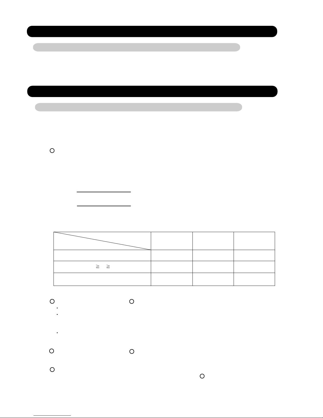
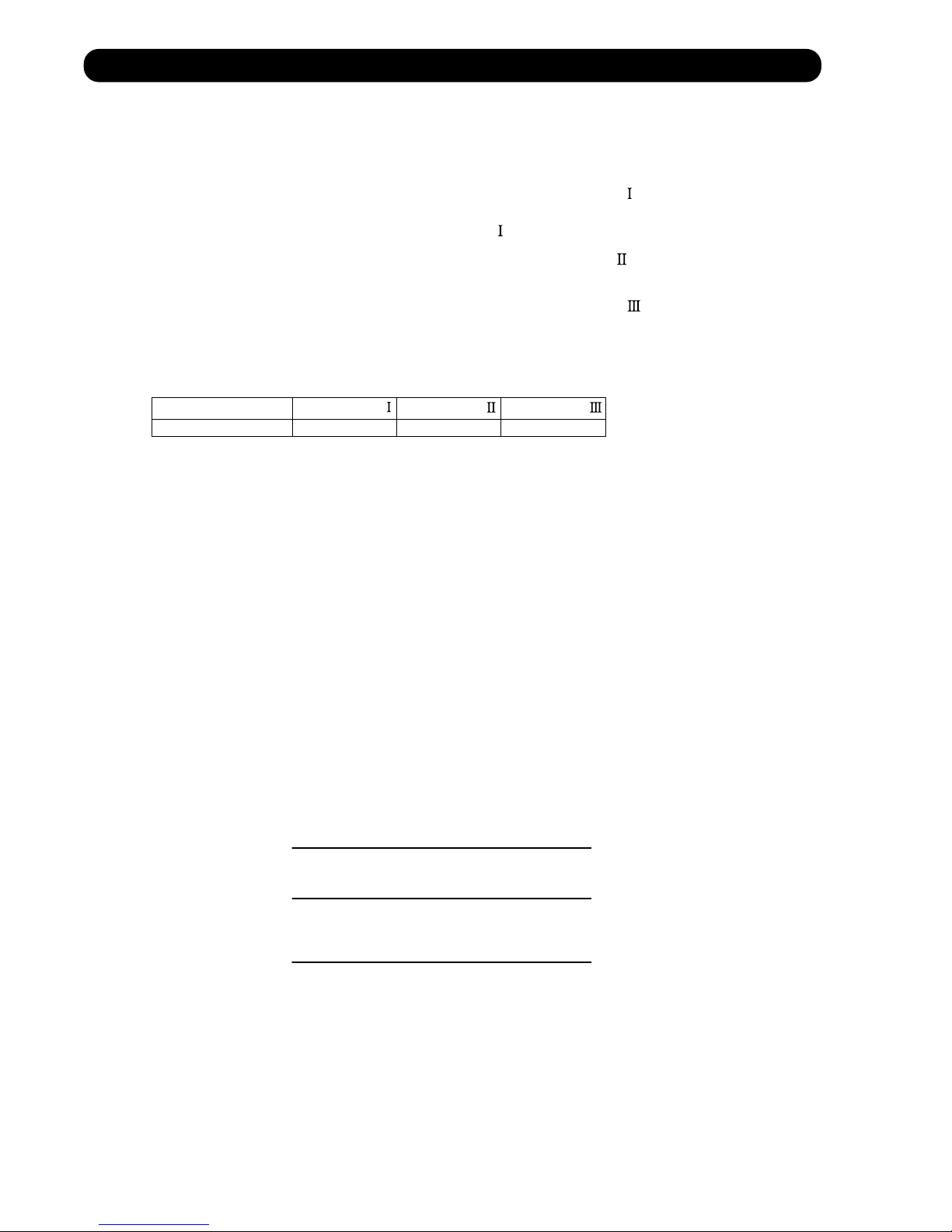
When the air conditioner is set to the AUTO mode by remote control, operation starts in the optimum
mode from among the HEATING, COOLING, DRY and MONITORING modes. During operation, the
optimum mode is automatically switched in accordance with temperature changes. The temperature
can be set between 64°F(18°C) and 88°F(30°C) in 2°F(1°C) steps.
.When operation starts, only the indoor and outdoor fans are operated for 1 minute. After 1 minute,
1
the room temperature and outside air temperature are sensed and the operation mode is
selected in accordance with the table below.
( Fig.1 : Outside air temperature zone selection )
C zone
90°F(32°C)
B zone
32°F(0°C)
A zone
( Table.1 Operation mode selection table)
Outside air temperature (TO)
Room temperature (TB)
TB > TS+4°F(2°C)
TS+4°F(2°C) TB TS - 4°F(2°C)
<
TB TS- 4°F(2°C) Heating Heating Monitoring
2
.When COOING was selected at , the air conditioner operates as follow:
The same operation as COOLING OPERATION of item 1 above is performed.
When the room temperature has remained at (set temperature -2°F(1°C)) for 8 minutes, operation is
automatically switched to DRY and the same operation as DRY OPERATION of item 3 above
is performed.
If the room temperature reaches (set temperature +4°F(2°C) during DRY operation, operation returns to
COOLING operation.
1
A zone B zone C zone
Monitoring
Monitoring Monitoring Monitoring
Cooling
(automatic dry)
Cooling
(automatic dry)
3
.When HEATING was selected at , the same operation as HEATING OPERATION of item 2
above is performed.
4
When the compressor was stopped for 6 consecutive minutes by the temperature control function
after the COOLING or HEATING operation mode was selected at above, operation is switched
to MONITORING and the operation mode is selected again.
1
1
01-01
Page 5
2-2 For AR type
When the air conditioner is set to the AUTO mode by remote control, operation starts in the optimum
mode from among the HEATING, COOLING and MONITORING modes. During operation, the
optimum mode is automatically swiched in accordance with temperature changes. The temperature
can be set between 18°C and 30°C in 1 degC steps.
When operation starts, only the indoor fan is operated for 1 minute. (Air flow mode: S- Lo)
1
After 1 minute, depends on the room temperature and outdoor unit's operarion mode,
the operation mode is selected in accordance with the table below.
( Table 1 : Operation mode selection table )
Room temperature :TR
TR > Ts +2 degC
=
Ts +2 degC > TR > Ts-2 degC
Ts +2 degC > TR
Ts : Setting temperature
TR: Room temperature
2
When COOLING was selected at , the same operation as COOLING OPERATION is performed.
3
When HEATING was selected at , the same operation as HEATING OPERATION is performed.
4
When the compressor was stopped for 6 consecutive minutes by the temperature control function
after the COOLING or HEATING operation mode was selected at above, operation is switched
to MONITORING and the operation mode is selected again.
=
Operation mode
Cooling
Monitoring
Heating
1
1
1
01-02
Page 6
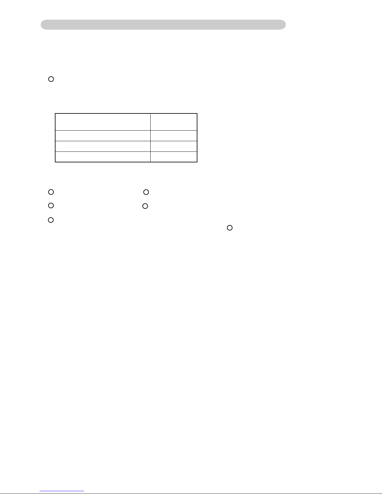
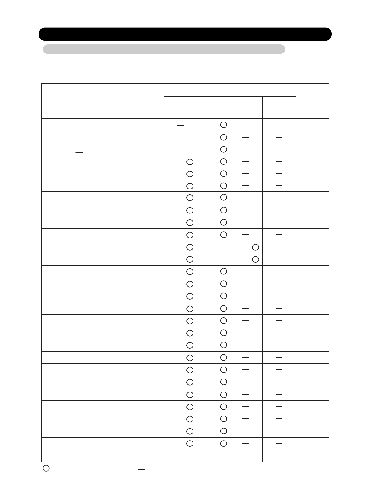
3. INDOOR FAN CONTROL
(1).Fan speed
( Table 2 : Indoor Fan Speed )
ASU9RMLQ
Operation mode Air flow mode Speed (rpm)
Heating
Cooling
Dry 8 00
ASU18RMLQ
Operation mode Air flow mode Speed (rpm)
Heating
Cooling
Dry 1,060
Hi 1,200
Me+ 1,200
Me 1,070
Lo 970
Quiet 850
Cool air
prevention
S-Lo 480
Hi 1,200
Me 1,070
Lo 900
Quiet 800
Hi 1,480
Me+ 1,480
Me 1,380
Lo 1,200
Quiet 1,060
Cool air
prevention
S-Lo 480
Hi 1,480
Me 1,380
Lo 1,200
Quiet 1,060
800
850
Operation mode Air flow mode Speed (rpm)
Heating
Cooling
Dry 9 00
ASU12RMLQ
prevention
Hi 1,380
Me+ 1,380
Me 1,230
Lo 1,110
Quiet 960
Cool air
S-Lo 480
Hi 1,380
Me 1,230
Lo 1,050
Quiet 900
850
ARU9RML
Operation mode Air flow mode Speed (rpm)
Heating
Cooling
Quiet
Cool air
prevention
Dry
ARU18RML
Operation mode Air flow mode Speed (rpm)
Heating
Cooling
Quiet
Cool air
prevention
Dry
Hi
Me
Lo
S-Lo
Hi
Me
Lo
S-Lo
1,070
880
800
800
450
450
800
1,010
850
800
800
350
350
800
ARU12RML
Operation mode Air flow mode Speed (rpm)
Heating
Cooling
Quiet
Cool air
prevention
Dry
Hi
Me
Lo
S-Lo
01-03
850
790
700
700
310
310
700
Page 7
AUU9RML
AUU12RML
Operation mode Air flow mode
Cooling
Fan
Heating
Dry
Monitoring
Hi 590
Me
Lo
Quiet
Hi
Me+
Me
Lo
Quiet
Auto
S- Lo
AUU18RML
Operation mode Air flow mode
Cooling
Fan
Heating
Dry
Monitoring
Hi 790
Me
Lo
Quiet
Hi
Me+
Me
Lo
Quiet
Auto
S- Lo
Speed (rpm)
540
490
440
590
570
540
490
440
460
300
Speed (rpm)
660
570
460
840
800
750
650
500
460
300
Operation mode Air flow mode
Cooling
Fan
Heating
Dry
Monitoring
Hi 660
Me
Lo
Quiet
Hi
Me+
Me
Lo
Quiet
Auto
S- Lo
Speed (rpm)
580
520
460
650
620
580
520
460
460
300
(2).FAN OPERATION
The airflow can be switched in 5 steps such as AUTO, QUIET, LOW, MED, HIGH, while the indoor
fan only runs.
When Fan mode is set at (Auto), it operates on (MED) Fan Speed. < for AS, AU type >
it operates intermittent on (LO) Fan speed and (OFF)
by one minute. <for AR type>
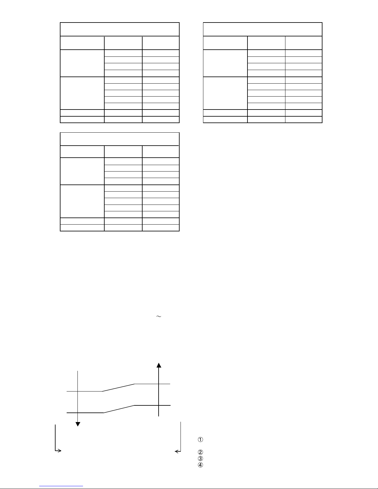
(3). COOLING OPERATION
Switch the airflow [AUTO], and the indoor fan motor will run according to a room temperature,
as shown in Figure 2.
On the other hand, if switched in [HIGH] [QUIET], the indoor motor will run at a constant airflow of [COOL]
operation modes QUIET, LOW, MED, HIGH,as shown in Table 2.
(Fig.2)
airflow change - over ( Cooling: AUTO )
Hi mode
+4°F(+2°C)
Me mode
+2°F(+1°C)
Lo mode
*1
When the room
temperature rises
+6°F(+3.0°C)
+5°F(+2.5°C))
*(
+3°F(+1.5°C)
(+3°F ) (+1.5°C)
*
*For AS / AU / Type
When the room
temperature lowers
(Room temperature) D (Setting temperature)
*1 : Contains a condition to the following
When the operation mode is set to AUTO mode
at the start of operation.
When the setting temperature was changed.
When the operation mode was changed to COOLING mode.
When the airflow mode was changed to AUTO mode.
01-04
Page 8
(4). DRY OPERATION
During the dry mode operation, the fan speed setting can not be changed.
The indication of the remote controller is fixed in [AUTO].
The fan operates on [S-Lo] mode or OFF.
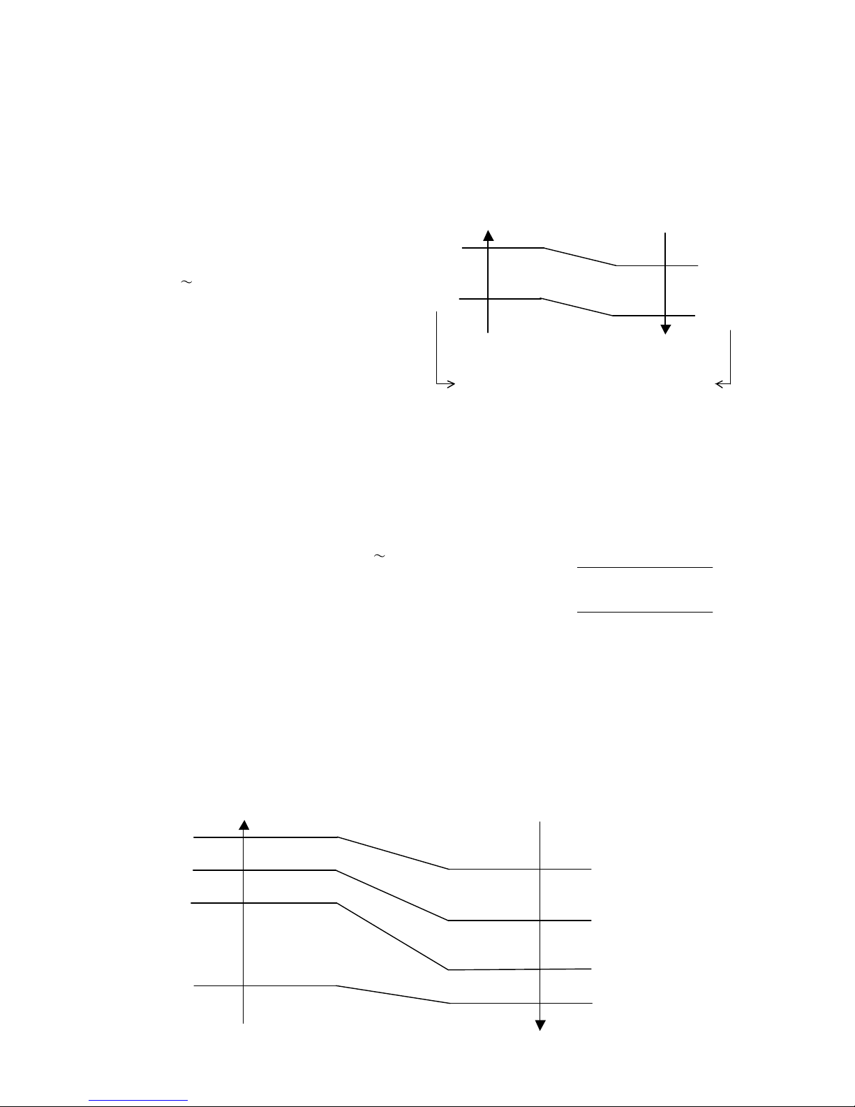
(5). HEATING OPERATION
5-1. For AU / AS Type
Switch the airflow [AUTO], and the
indoor fan motor will run according
to a room temperature, as shown in
Figure 3.
On the other hand, if switched
[HIGH]
[QUIET], the indoor motor
will run at a constant airflow of [HEAT]
operation modes QUIET, LOW, MED,
HIGH, as shown in Table 2.
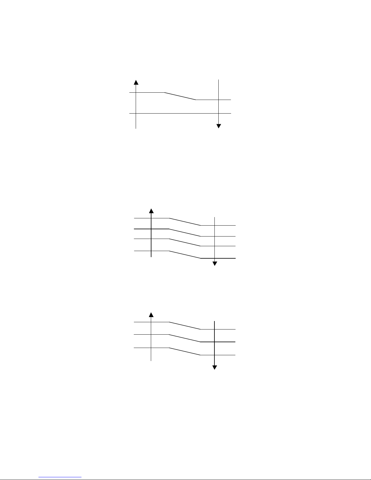
5-2. For AR Type
When the airflow is set to [AUTO], the indoor fan
motor operates [MED] mode.
Then the indoor fan motor will run according
to a room temperature, as shown in Figure 4.
On the other hand, if switched in [HIGH] [QUIET],
the indoor motor will run at a constant airflow
of [HEAT] operation modes QUIET, LOW, MED, HIGH,
as shown in Table 2.
-2°F(-1°C)
-4°F(-2°C)
(Fig.3)
airflow change - over ( Heating: AUTO)
When the room
temperature rises
LOW mode
-3°F(-1.5°C)
MED mode
-5°F(-2.5°C)
MED + mode
(Room temperature) - (Setting temperature)
When the room
temperature lowers
( Fig.4 : Airflow change - over ( Heating : AUTO ) )
Indoor heat exchanger
temperature
Go up one-step
117°F(47°C)
Hold
105.8°F(41°C)
Go down one-step
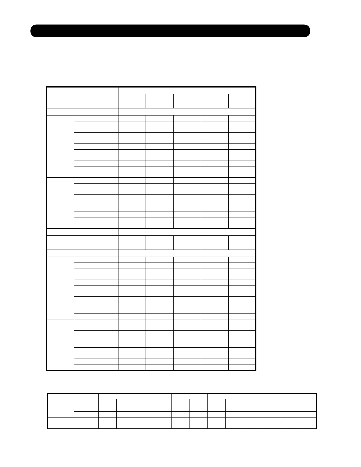
(6). COOL AIR PREVENTION CONTROL (Heating mode)
6-1. For AS Type
The maximum value of the indoor fan speed is set as shown in Figure 5, based on the detected
temperature by the indoor heat exchanger sensor on heating mode.
(Fig.5 : Cool Air Prevention Control)
Indoor heat exchanger Indoor heat exchanger
temperature temperature
117°F(47°C)
104°F(40°C)
99°F(37°C)
(30°C)
86°F
Hi
Me+
Lo
Cool air prevention
S-Lo
01-05
104°F(40°C)
93°F(34°C)
90°F(32°C)
82°F(28°C)
Page 9
6-2. For AR Type
The maximum value of the indoor fan speed is set as shown in Figure 6, based on the detected
temperature by the indoor heat exchanger sensor on heating mode.
( Fig.6 : Cool Air Prevention Control )
Indoor heat exchanger
temperature
Indoor heat exchanger
temperature
Setting
91.4°F(33°C)
Fan mode
Lo mode
86°F(30°C)
86°F(30°C)
S-Lo mode
6-3. For AU Type
When the compressor operates, the maximum value of the indoor fan speed is set as shown in Figure 7,
based on the detected temperature by the indoor heat exchanger sensor on heating mode.
When the compressor does not operate, the indoor fan motor operates [S-Lo] mode.
( Fig.7 : Cool Air Prevention Control )
< [Hi] setting >
Indoor heat exchanger
temperature
107.6°F(42°C)
102.2°F(39°C)
99°F(37°C)
86°F(30°C)
Hi
Me+
Lo
Cool air
prevention
S-Lo
Indoor heat exchanger
temperature
99°F(37°C)
93°F(34°C)
90°F(32°C)
75.2°F(24°C)
Indoor heat exchanger
temperature
102.2°F(39°C)
99°F(37°C)
86°F(30°C)
< The other of [Hi] setting >
Setting
FAN mode
Lo (Qu)
Cool air
prevention
S-Lo
Indoor heat exchanger
temperature
01-06
93°F(34°C)
90°F(32°C)
75.2°F(24°C)
Page 10
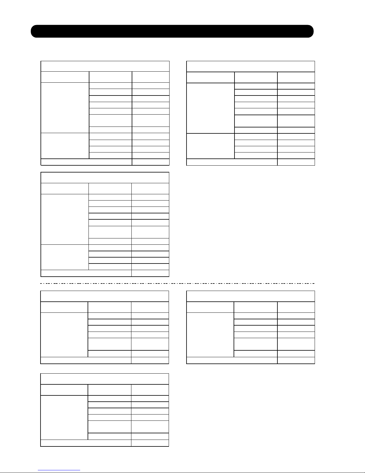
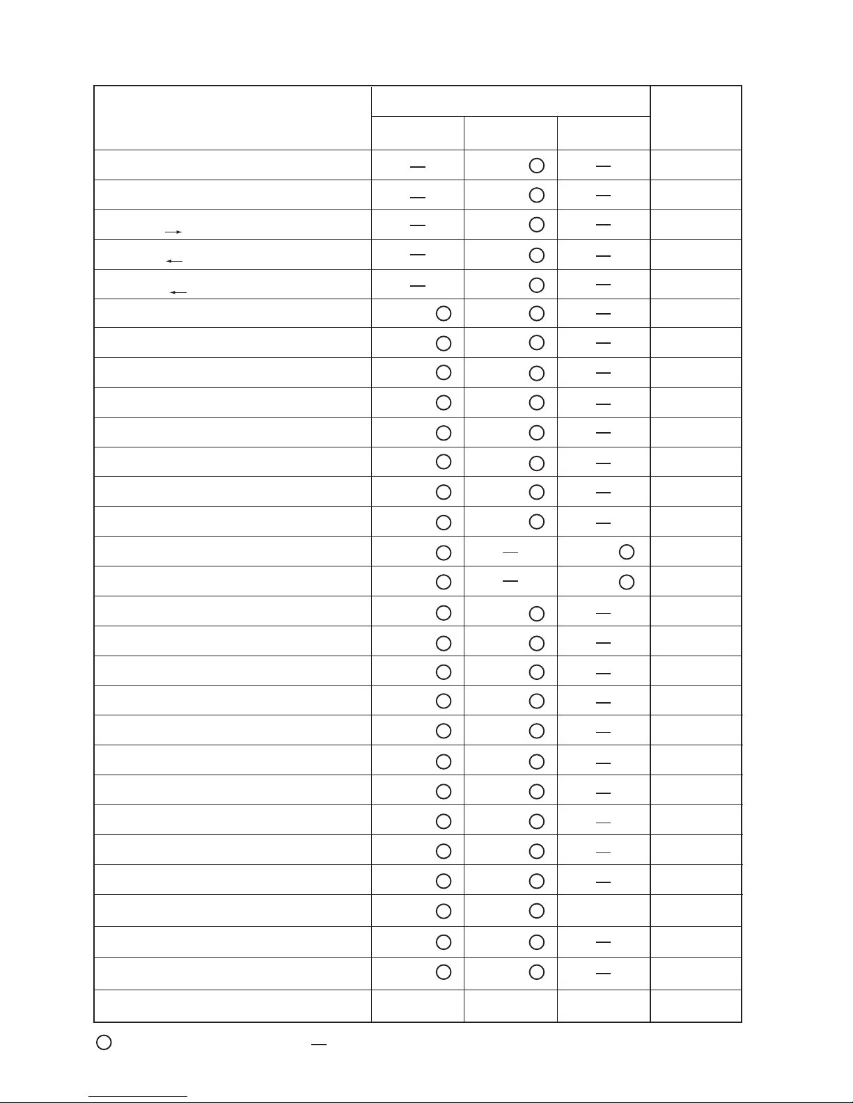
4. OUTDOOR FAN CONTROL
(1). Fan Speed
The speed of outdoor unit fan motor is determined at outside temperature and compressor rotation.
( Table 2 : Target fan speed )
AOU24/36RML
Frequency rise
Frequency down
Outdoor temperature
Cooling
Heating
AOU24/36RML
Frequency rise
Frequency down
Outdoor temperature
Cooling
Heating
Compressor rotation [Hz]
<
10 F<20 20 F<30 30 F<40 40 F<50 50 F<60
=
<
7 F<17 17 F<27 27 F<37 37 F<47 47 F<57
=
<
=
<
=
<
=
<
=
<
=
<
=
<
=
<
=
Fan rotation
>
Tout 45 HI HI HI HI HI
=
>
45>Tout 38 HI HI HI HI HI
=
>
38>Tout 31 HI HI S-HI S-HI S-HI
=
>
31>Tout 26 MED HI HI HI HI
=
>
26>Tout 22 LOW MED MED HI HI
=
>
22>Tout 18 LOW MED MED MED MED
=
>
18>Tout 12 S-LOW S-LOW LOW MED MED
=
>
12>Tout 7 S-LOW S-LOW S-LOW LOW LOW
=
>
7>Tout 3 S-LOW S-LOW S-LOW LOW LOW
=
>
3>Tout -3 S-LOW S-LOW S-LOW S-LOW LOW
=
-3>Tout S-LOW S-LOW S-LOW S-LOW S-LOW
>
Tout 24 S-LOW S-LOW LOW LOW MED
=
>
24>Tout 20 S-LOW S-LOW LOW LOW MED
=
>
20>Tout 16 LOW MED MED HI HI
=
>
16>Tout 12 MED HI HI HI HI
=
>
12>Tout 5 HI HI HI H-HI H-HI
=
>
5>Tout -1 H-HI H-HI H-HI H-HI H-HI
=
>
-1>Tout -6 H-HI H-HI H-HI H-HI H-HI
=
>
-6>Tout -11 H-HI H-HI H-HI H-HI H-HI
=
-11>Tout H-HI H-HI H-HI H-HI H-HI
Compressor rotation [Hz]
<
60 F<70 70 F<80 80 F<90 90 F
=
<
57 F<67 67 F<77 77 F<87 87 F
=
<
=
<
=
<
=
<
=
<
=
<
=
Fan rotation
>
Tout 45 HI HI HI HI
=
>
45>Tout 38 HI HI HI HI
=
>
38>Tout 31 S-HI S-HI S-HI S-HI
=
>
31>Tout 26 HI HI S-HI S-HI
=
>
26>Tout 22 HI HI HI HI
=
>
22>Tout 18 HI HI HI HI
=
>
18>Tout 12 MED HI HI HI
=
>
12>Tout 7 MED MED MED HI
=
>
7>Tout 3 LOW MED MED MED
=
>
3>Tout -3 LOW LOW LOW MED
=
-3>Tout LOW LOW LOW LOW
>
Tout 24 MED MED MED HI
=
>
24>Tout 20 MED MED MED HI
=
>
20>Tout 16 HI HI HI HI
=
>
16>Tout 12 HI HI HI HI
=
>
12>Tout 5 H-HI H-HI H-HI H-HI
=
>
5>Tout -1 H-HI H-HI H-HI H-HI
=
>
-1>Tout -6 H-HI H-HI H-HI H-HI
=
>
-6>Tout -11 H-HI H-HI H-HI H-HI
=
-11>Tout H-HI H-HI H-HI H-HI
( Table 4 : Outdoor fan speed )
Speed
Mode Cooling Heating Cooling Heating Cooling Heating Cooling Heating Cooling Heating Cooling Heating
AOU24RML
AOU36RML
Upper Fan 780 780 780 780 780 780 400 400 300 300 200 200
Lower Fan 780 780 780 780 780 780 400 400 300 300 200 200
Upper Fan 850 900 850 900 780 780 400 400 300 300 200 200
Lower Fan 850 900 850 900 780 780 400 400 300 300 200 200
H-HI S-HI HI MED
LOW S-LOW
(rpm)
01-07
Page 11
5. LOUVER CONTROL
5-1 Wall Mounted ( AS ) type
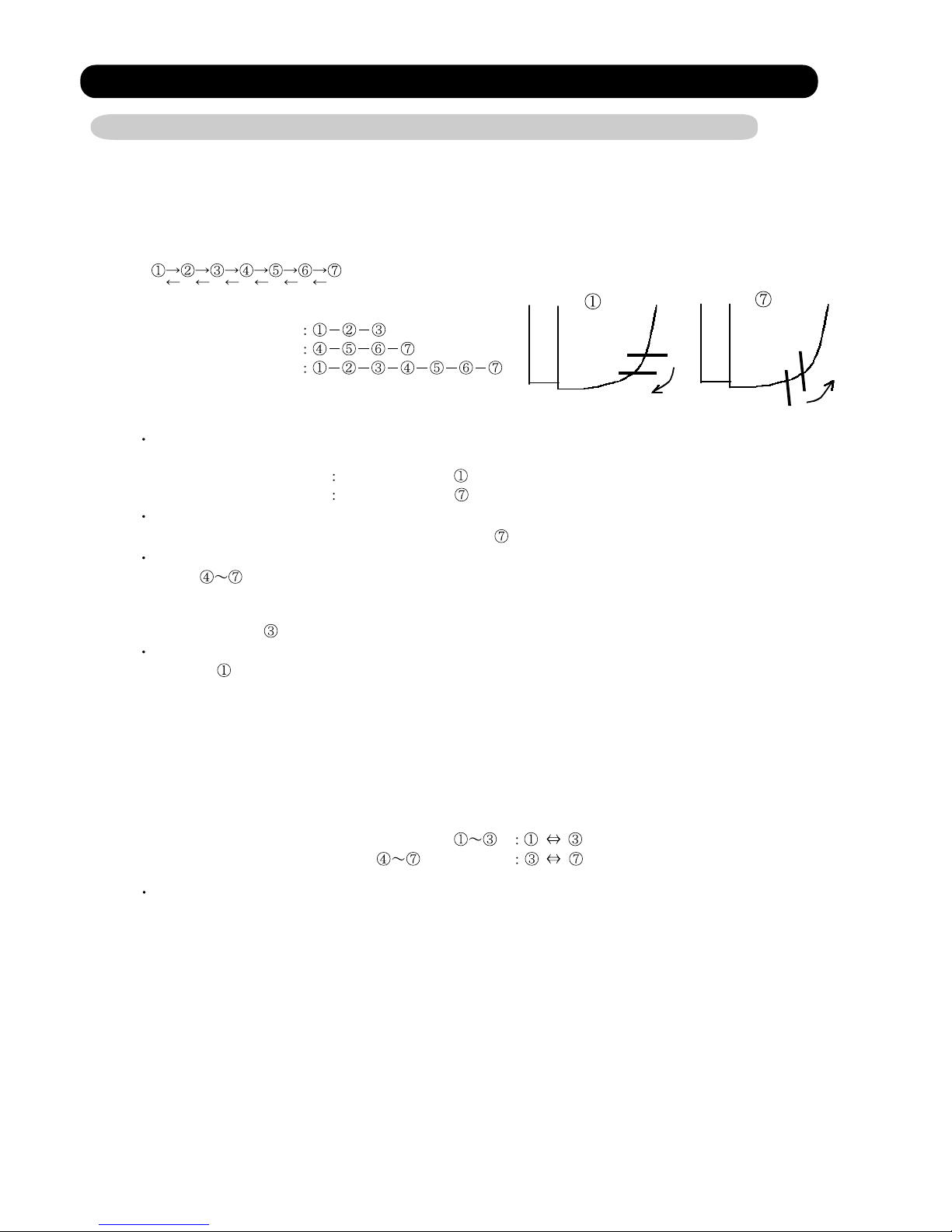
(1). VERTICAL LOUVER CONTROL
(Function Range)
Each time the button is pressed, the air direction range will change as follow:
(Fig 5: Air Direction Range)
(Operation Range)
Cooling / Dry mode
Heating mode
Fan mode
Use the air direction adjustments within the ranges shown above.
The vertical airflow direction is set automatically as shown, in accordance with the type of operation
selected.
When the temperature of the air being blown out is low at the start of heating operation or during
defrosting, the airflow direction temporarily becomes
During use of the Cooling and Dry modes, do not set the Air Flow Direction Louver in the Heating
range (
drop of water may drip from the air conditioner. During the Cooling and Dry modes, if the Air Flow
Direction Louvers are left in the hating range for more than 30 minutes, they will automatically
return to position
During Monitor operation in AUTO CHANGEOVER mode, the airflow direction automatically
becomes
Cooling / Dry mode
Heating mode
) for long period of time, since water vapor many condense near the outlet louvers and
.
, and it cannot be adjusted.
Horizontal flow
Downward flow
to prevent cold air being blown onto the body.
(2). SWING OPERATION
When the swing signal is received from the remote controller, the vertical louver starts to
swing.
(Swinging Range)
Cooling mode / Dry mode / Fan mode(
Heating mode / Fan mode(
When the indoor fan is either at S-lo or Stop mode, the swinging operation is interrupted
and the louver stops at the memorized position.
)
)
01-08
Page 12
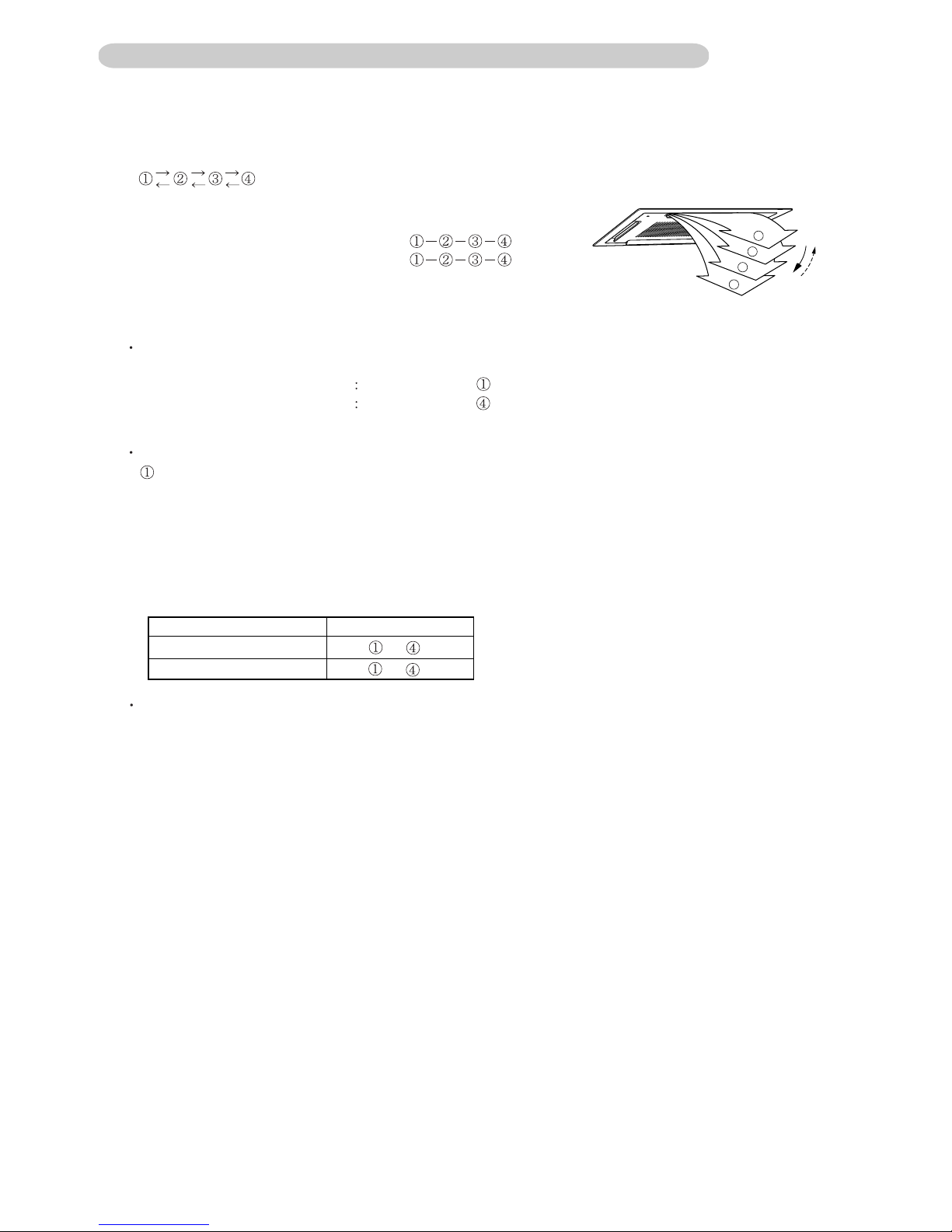
5-2 Cassette (AU) type
1. VERTICAL LOUVER CONTROL
(Function Range)
Each time the button is pressed, the air direction range will change as follows:
(Air Direction Range)
(Operation Range)
During Cooling/Dry mode/Fan mode :
During Heating mode :
Use the air direction adjustments within the ranges shown above.
3
4
The vertical airflow direction is set automatically as shown, in accordance with the type of operation
selected.
Cooling / Dry / Fan mode
Horizontal flow
Heating mode Downward flow
During AUTO mode operation, for the first minute after beginning operation, air-flow will be horizontal
; the air direction cannot be adjusted during this period.
1-2. SWING OPERATION
When the swing signal is received from the remote controller, the vertical louver starts to swing.
The range of swing depends on the set airflow direction.
(Swinging Range)
The type of operation
Cooling/Dry/Fan
Heating
Range of swing
to
to
1
2
When the indoor fan is either at S-Lo or Stop mode, the swinging operation is interrupted
and the louver stops at the memorized position.
( Stop mode means Operation stop.)
01- 09
Page 13
6. COMPRESSOR CONTROL
(1). OPERATION FREQUENCY RANGE
The operation frequency of the compressor is different based on the operation mode as
shown in the table 4.
(Table 4 : Compressor Operation Frequency Range)
Cooling Heating
Min Max Min Max
AOU24RML 15Hz 90Hz 20Hz 95Hz
AOU36RML 15Hz 90Hz 20Hz 95Hz
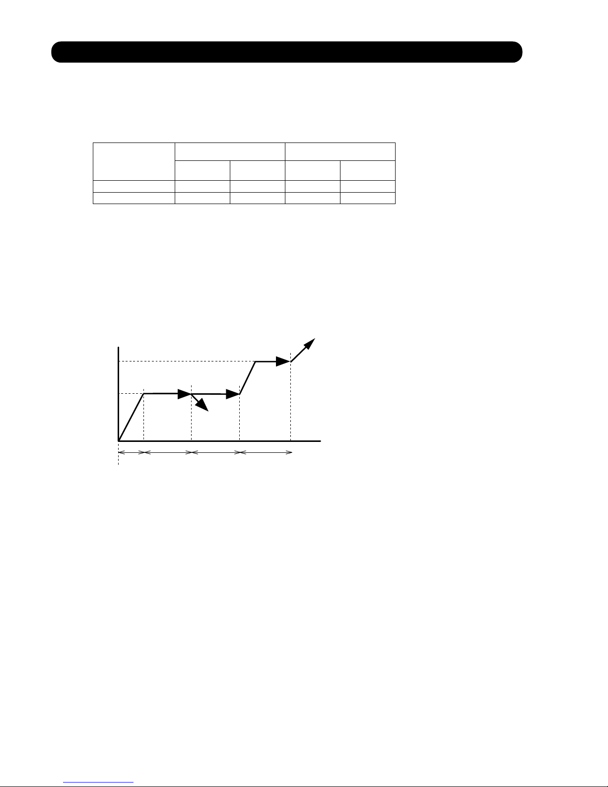
(2). OPERATION FREQUENCY CONTROL AT START UP
The compressor frequency soon after the start-up is controlled as shown in the figure 6.
(Fig.6 : Compressor Control at Start-up)
56rps
40rps
46
134 120 (Sec)60~720
1) Compressor operates for 180 seconds by 40 rotations.
2) In the case of lower than 40 rotations, it operates at these rotations.
3) Compressor operates for 60 to 720 seconds.
When discharge temperature exceeds 30 degrees in the meantime, it shifts to 56 rotations.
4) Compressor operates at target rotations after 120 second operation.
01-10
Page 14
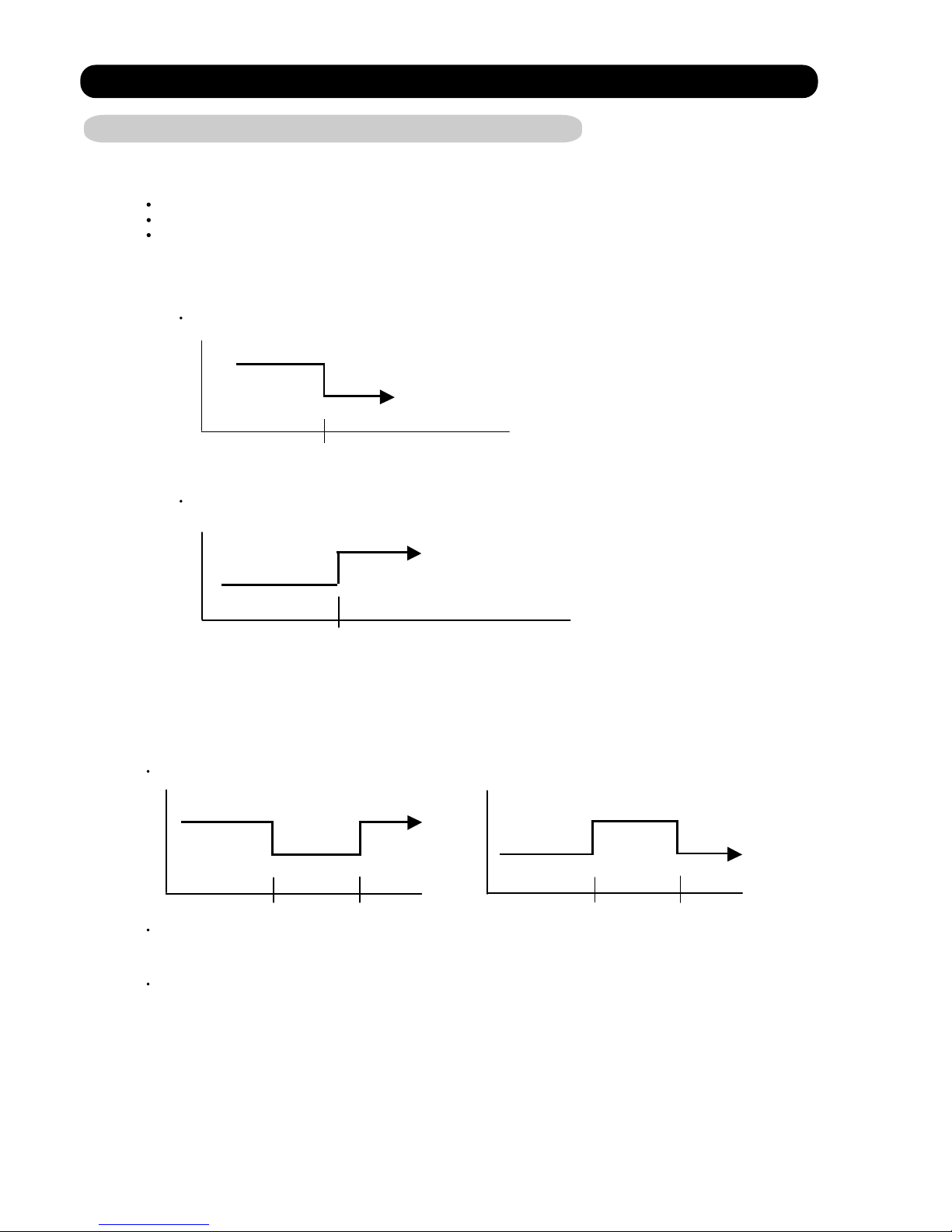
7. TIMER OPERATION CONTROL
7-1 Wireless Remote Controller
For AS type
ON / OFF TIMER
PROGRAM TIMER
SLEEP TIMER
(1). OPERATION FREQUENCY RANGE
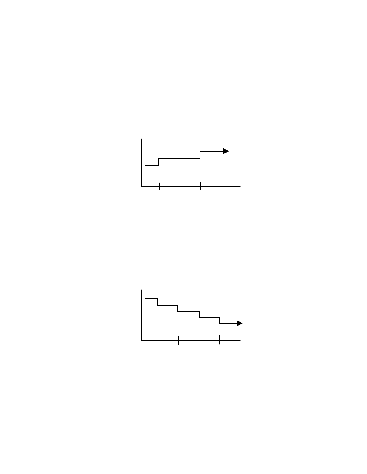
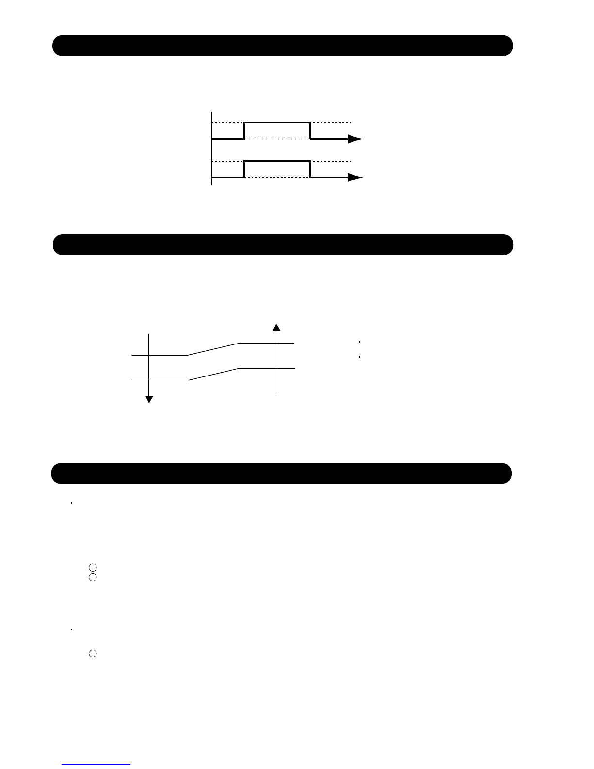
OFF timer : When the clock reaches the set time, the air conditioner will be turned off.
Operation mode
Stop mode
Set time of timer
ON timer : When the clock reaches the set time, the air conditioner will be turned on.
Operation mode
Stop mode
Set time of timer
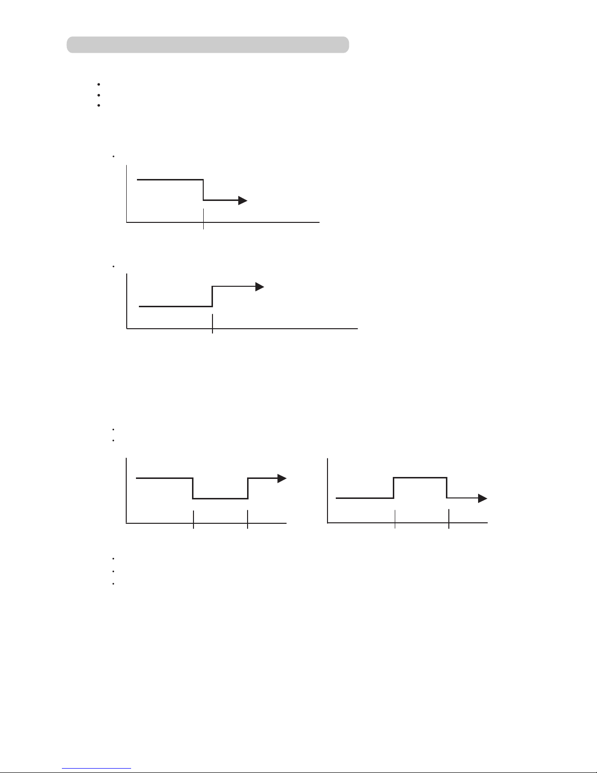
(2). PROGRAM TIMER
The program timer allows the OFF timer and ON timer to be used in combination one time.
Operation mode
Stop mode
Set time
Operation mode
Stop mode
Set time Set time Set time
Operation mode
Stop mode
Operation will start from the timer setting (either OFF timer or ON timer) whichever is closest
to the clock's current timer setting. The order of operations is indicated by the arrow in the remote
control unit's display.
SLEEP timer operation cannot be combined with ON timer operation.
01-11
Page 15
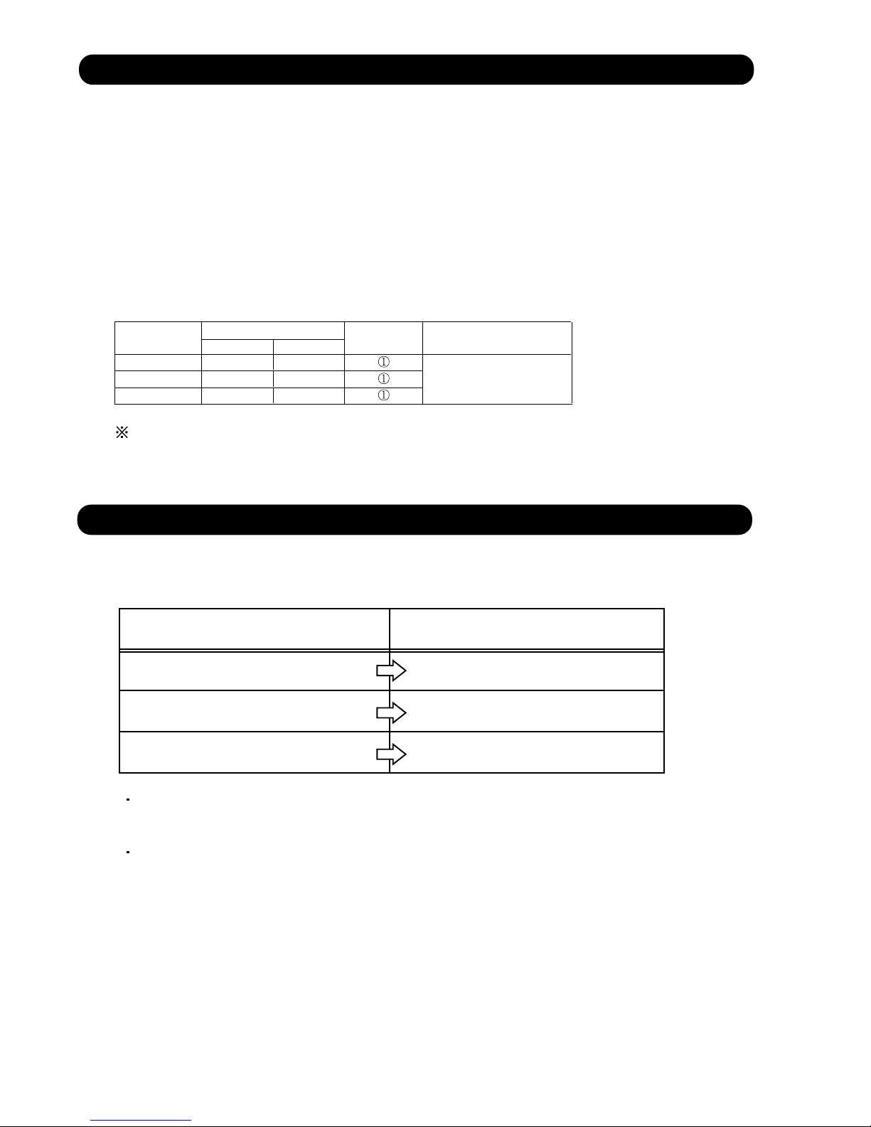
(3). SLEEP TIMER
If the sleep is set, the room temperature is monitored and the operation is stopped automatically.
If the operation mode or the set temperature is change after the sleep timer is set, the operation is
continued according to the changed setting of the sleep timer from that time ON.
In the cooling operation mode
When the sleep timer is set, the setting temperature is increased 2°F(1°C).
It increases the setting temperature another 2°F(1°C) after 1 hour.
After that, the setting temperature is not changed and the operation is stopped at the time
of timer setting.
Set temperature rises
( Ts : Set temperature )
+4°F(+2°C)
+2°F(+1°C)
Ts
Stop of operation
Set
60min
In the heating operation mode
When the sleep timer is set, the setting temperature is decreased 2°F(1°C).
It decreases the setting temperature another 2°F(1°C) every 30 minutes.
Upon lowering 8°F(4°C), the setting temperature is not changed and the operation stops at
the time of timer setting.
Set temperature lowers
( Ts : Set temperature )
Ts
-2°F(-1°C)
-4°F(-2°C)
-6°F(-3°C)
-8°F(-4°C)
Stop of operation
Set
30min
01-12
30min
30min
Page 16
7-2 Wired Remote Controller
For AR / AU type
ON / OFF TIMER
WEEKLY TIMER
TEMPERATURE SET BACK TIMER
1. ON / OFF TIMER
OFF timer : When the clock reaches the set time, the air conditioner will be turned off.
Operation mode
Set time of timer
ON timer : When the clock reaches the set time, the air conditioner will be turned on.
Stop mode
Stop mode
Operation mode
Set time of timer
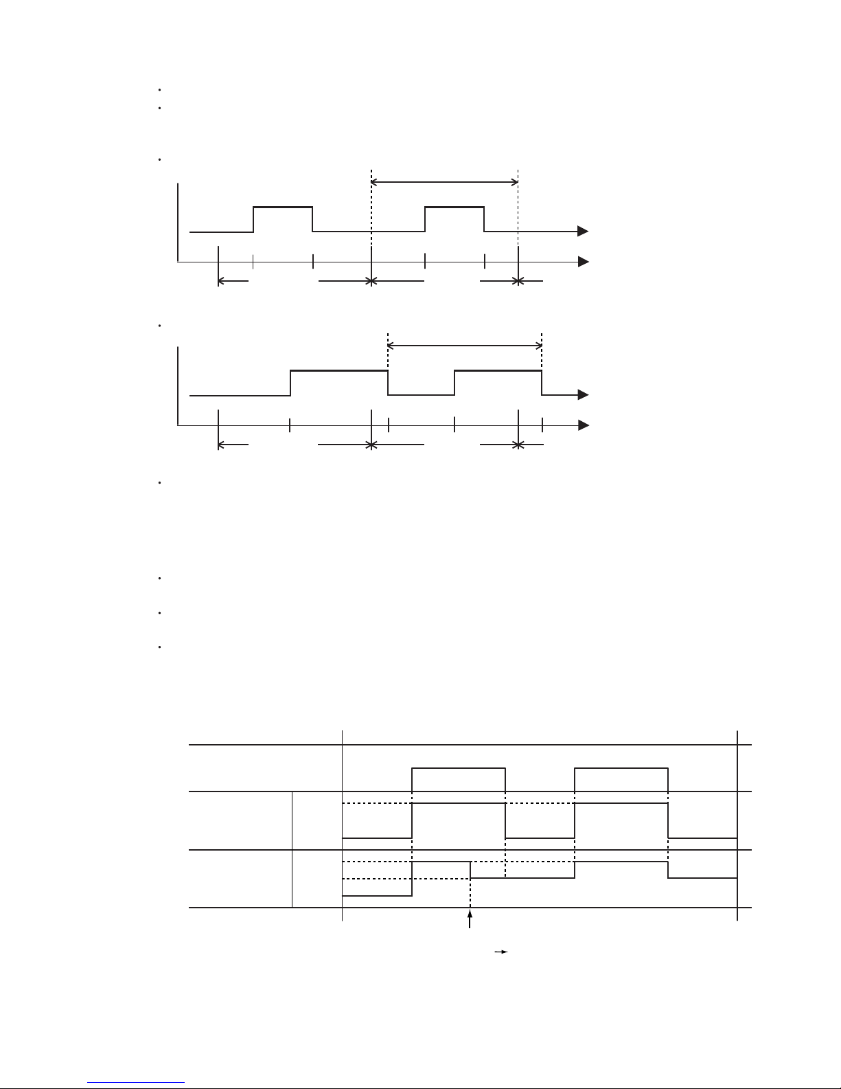
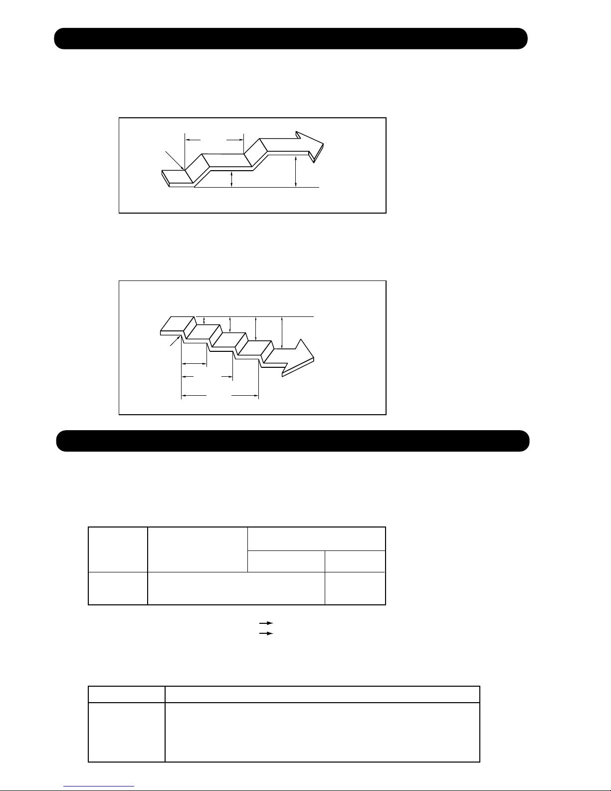
2. WEEKLY TIMER
2-1. WEEKLY TIMER
Use this timer function to set operating time for each day of the week.
The weekly timer allows up to two ON and OFF time to set up per day.
Operation mode
Stop mode
Set time
The operating time can be set in 30 min increments only.
The OFF time can be carried over to next day.
The ON timer and the OFF timer functions cannot be set with using the weekly timer.
Both ON and OFF time must be set.
Operation mode
Stop mode
Set time Set time Set time
Operation mode
Stop mode
01-13
Page 17
2-2. DAY OFF setting
The DAY OFF setting is only available for days for which weekly settings already exist.
If the operating time carries over to the next day (during a next day setting), the effective
DAY OFF range will be set as shown below.
Normal
DAY OFF
Operation mode
Operation mode
Stop mode
Stop mode
Preceding day Next day
Setting day
Stop mode
Next day setting
DAY OFF
Stop mode
Operation mode
Stop mode
Preceding day Next daySetting day
Operation mode
Stop mode
The DAY OFF setting can only be set one time. The DAY OFF setting is cancelled automatically
after the set day has passed.
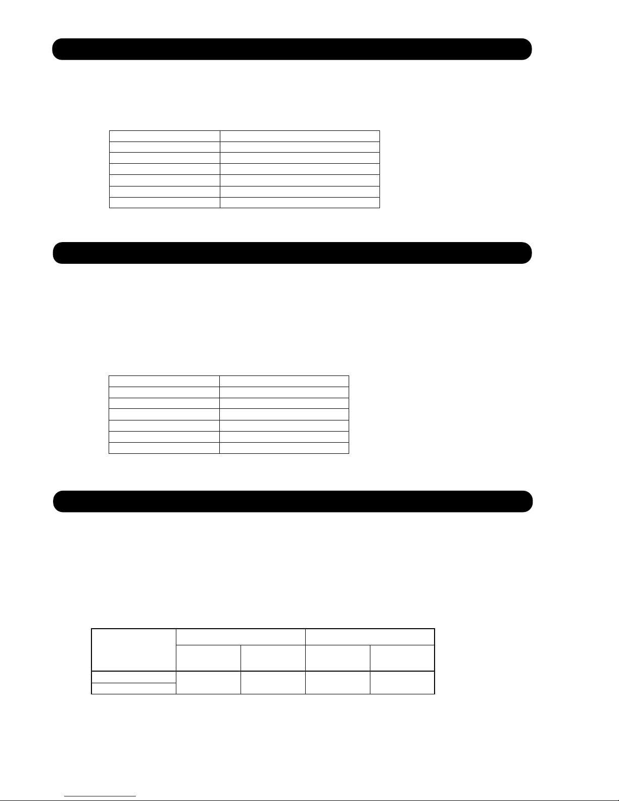
3. TEMPERATURE SET BACK TIMER
The SET BACK timer only changes the set temperature for 7 days, it cannot be used to start or stop
air conditioner operation.
The SET BACK timer can be set to operate up to two times per day but only one temperature setting
can be used.
During the COOL/DRY mode, the air conditioner will operate at a minimum of 18°C even if
the SET BACK temperature is set to 17
°C or lower.
Case of SET BACK timer on the Cooling operation.
( Setting temperature :22°C, SET BACK temperature :26°C)
SET BACK setting
Operation
temperature
*1
Operation
temperature
*1: During the SET BACK function,
the setting temperature is changed.
ON OFF OFFON
26°C
22°C
26°C
24°C
22°C
Chenge the setting temperature:
22°C 24°C
01-14
Page 18

8. ELECTRONIC EXPANSION VALVE CONTROL
The most proper opening of the electronic expansion valve is calculated and controlled under the
present operating condition based on the following values.
The compressor frequency, the temperatures detected by the discharge temperature sensor
and the outdoor temperature sensor.
The pulse range of the electronic expansion valve control is between 30 to 480 pulses.
At the time of supplying the power to the outdoor unit, the initialization of the electronic
expansion valve is operated (1000 pulses are input to the closing direction).
9. TEST OPERATION CONTROL
Under the condition where the air conditioner runs, press the test operation button of the remote
control, and the test operation control mode will appear. During test running, the operation lamp
and timer lamp of the air conditioner body twinkle simultaneously. Set the test operation mode,
and the compressor will continue to run regardless of whether the room temperature sensor detects.
The test operation mode is released if 60 minutes have passed after setting up the test operation.
10. PREVENT TO RESTART FOR 3 MINUTES ( 3 MINUTES ST )
The compressor won't enter operation status for 3 minutes after the compressor is
stopped, even if any operation is given.
11. FOUR-WAY VALVE EXTENSION SELECT
At the time when the air conditioner is switched from the cooling mode to heating mode,
the compressor is stopped, and the 4-way valve is switched in 3 minutes later
after the compressor stopped.
12. AUTO RESTART
When the power was interrupted by a power failure, etc. during operation, the operation contents
at that time are memorized and when power is recovered, operation is automatically started with
the memorized operation contents.
When the power is interrupted and recovered during timer operation, since the timer operation time
is shifted by the time the power was interrupted, an alarm is given by blinking (7 sec ON/2 sec OFF)
the indoor unit body timer lamp.
[Operation contents memorized when the power is interrupted]
Operation mode
Set temperature
Set air flow
Timer mode and timer time
Set air flow Direction
Swing
The detection position of the thermistor (When it used the wired remote controller for AS and AU)
01-15
Page 19
13. MANUAL AUTO OPERATION (Indoor unit body operation)
If MANUAL AUTO Button is set, the operation is controlled as shown in Table 6.
If the remote control is lost or battery power dissipated, this function will work without the remote
control.
(Table 6)
Manual auto operation
OPERATION MODE Auto changeover
FAN CONT. MODE Auto
TIMER MODE Continuous
SETTING TEMP. 75°F(24°C)
SETTING LOUVER Standard
SWING OFF
(No timer setting available)
14. FORCED COOLING OPERATION
Forced cooling operation is started when pressing MANUAL AUTO button for 10 seconds or more.
During the forced cooling operation, it operates regardless of room temperature sensor.
Operation LED and timer LED blink during the forced cooling operation. They blink for 1 second ON
and 1 second OFF on both operation LED and timer LED (same as test operation).
Forced cooling operation is released after 60 minutes of starting operation.
The FORCED COOLING OPERATION will start as shown in Table 7.
(Table 7)
Forced cooling operation
OPERATION MODE
FAN CONT. MODE
TIMER MODE
SETTING TEMP.
SETTING LOUVER
SWING
Cooling
Hi
Room Temp is not controlled
Horizontal
OFF
15. COMPRESSOR PREHEATING
When the outdoor heat exchanger temperature is lower than Operation temperature (Refer to Table 8)
and the heating operation has
the compressor is heated.
(By heating the compressor, warm air is quickly discharged when operation is started.)
When operation was started, and when the outdoor temperature rises to Release temperature or greater,
preheating
is over.
(Table 8 : Preheating Operation / Release Temperature)
Operation
temperature
AOU24RML
AOU36RML
been stopped for 3 hours, power is applied to the compressor and
Before 24 hour After 24 hour
Operation
temperature
32°F
(0°C)
Release
temperature
39.2°F
(4°C)
37.4°F
(3°C)
Release
temperature
44.6°F
(7°C)
01-16
Page 20
16. FRESH AIR CONTROL (For AR type)
The fan motor for Fresh Air is operated in synchronization with the indoor fan operation
as shown in Figure 11.
(Fig.11 : Fresh air control)
Fan motor
(Indoor unit)
Fan motor
(for Fresh Air)
Operation
Stop
Operation
Stop
17. EXTERNAL ELECTRICAL HEATER CONTROL (For AR type)
The external electrical heater is operated as shown in Figure 12.
(Fig.12 : External electrical heater control)
When the room
temperature rises
Heater : OFF
Ts -1°C
Ts -3°C
Ts -12°C
Heater : ON
Heater : OFF
Ts -10°C
Ts : Setting temperature
When the compressor stop,
External electrical heater is OFF.
When the room
temperature drops
18. DRAIN PUMP OPERATION ( For AU, *AR type )
During Cooling / Dry operation
1. When the compressor starts, the drain pump starts simultaneously.
2. The drain pump operates continuously for 3 minutes after the compressor is turned off.
3. When the compressor stops by the "Indoor heat exchanger de-icing function", the drain pump is turned off in 1 hour
after the compressor stops.
4.When the water level in the drain pan rises up and then the float switch functions:
The compressor, indoor and outdoor fan motor operation are stopped.
1
2
Drain pump operates continuously for 3 minutes after the float switch is turned off.
(Almost condensing water may be drained)
5. When the float switch turns ON continuously for 3 min., "FAILURE INDICATION" operates.
6. When the float switch turns OFF within 3 min., the unit starts cooling operation.
During Heating / Fan / Stop operation
1.When the water level in the drain pan rises up and then the float switch functions:
Drain pump operates continuously for 3 minutes after the float switch is turned off.
1
(Almost condensing water may be drained)
2. When the float switch turns ON continuously for 3 min., "FAILURE INDICATION" operates.
*When installed the drain pump which procured locally, it operates
01-17
Page 21
19. COIL DRY AND CLEAN OPERATION CONTROL (For AS type)
The coil-dry and clean operation functions by pressing COIL DRY button on the remote controller.
The coil-dry operation is consisted of 3 cycles of [Fan operation 3 minutes / Heating operation
2 minutes], and Fan operates for 3 minutes at last before ending the air conditioner operation.
(It takes 18 minutes to complete the coil-dry operation.)
It continues from coil-dry operation, it turns on electricity to Air clean unit, sterilization is
performed for 15 minutes.
Indoor unit fan motor operation under coil-clean operation : The cycle of 480rpm Fixation
5 sec ON / 1 min OFF is repeated.
(It takes 33 minutes to complete the air cleaning operation.)
(Table 9: COIL-DRY AND CLEAN Operating Functions)
ASU9RMLQ
ASU12RMLQ
ASU18RMLQ
Indoor Fan Speed
coil-dry coil-clean
900rpm
900rpm
900rpm
480rpm
480rpm
480rpm
Louver
Position
Operating COIL DRY : ON
Other indication : OFF
Main Unit
Indication
MW09/ 12/ 18Y3FM model (For Friedrich) is only COIL-DRY OPERATION.
20. AIR CLEAN OPERATION (Only for ASU9/ 12/18RMLQ)
The air clean operation switches ON and OFF as follows
every time it receives AIR CLEAN signal from remote controller.
Status before receiving Air Clean signal Status upon receiving Air Clean signal
Operation stops
In operation
(Air Clean operation is OFF.)
Operation keeps stopping
It continues to operate
(Air Clean operation becomes ON.)
In operation
(Air Clean operation is ON.)
When Air Clean operation is ON, Indoor fan speed becomes at [S-Lo](480rpm),
and not at 0rpm even if the indoor fan is in stop condition.
Air Clean operation becomes OFF during the defrost operation.
It continues to operate
(Air Clean operation becomes OFF.)
01-18
Page 22
21. ENERGY SAVE FUNCTION (For AR type)
1. During Cooling / Dry operation:
The thermostat temperature setting increases by 1 degC as soon as the ENERGY SAVE button is pressed,
and then increases by 1 degC after 1 hour later.
Afterwards, energy consumption is saved by continuing to cool or dry at a thermostat temperature of 2 degC
higher than setting temperature.
ENERGY
SAVE ON
1hour.
1 degC
2 degC
Setting
temperature
2. During Heating operation:
The thermostat temperature setting decreases by 1 degC as soon as the ENERGY SAVE button is pressed,
and then decreases by another 1 degC every 30 minutes.
Afterwards, energy consumption is saved by continuing to heat at a thermostat temperature of 4 degC
lower than setting temperature.
ENERGY
SAVE ON
1degC 2degC 3degC 4degC
30min.
1 hour.
1 hour
30 min.
Setting
temperature
22. DEFROST OPERATION CONTROL
1. CONDITION OF STARTING THE DEFROST OPERATION
The defrost operation starts when the outdoor heat exchanger temperature sensor detects
the temperature lower than the values shown in Table 9.
(Table 9 : Condition of starting Defrost Operation)
Compressor integrating
Compressor integrating
operation :Less than 45min.
AOU24RML
AOU36RML
*1. It means contiguous operation time.
*2. Compressor stop time: Below 20min. Select 6min.
Above 20min. Select 10min.
Does not operate
2. CONDITION OF THE DEFROST OPERATION COMPLETION
Defrost operation is released when the conditions become as shown in Table 10.
(Table 10 : Defrost Release Condition)
AOU24RML
AOU36RML
Outdoor heat exchanger temperature sensor value is higher than 53.6°F(12°C) or
Compressor operation time has passed 15 minutes.
operation :45min and over
Less than 6 min. *1
or 10min. *2
Release Condition
After 6 min. *1
or 10min. *2
°F(-8°C) *3
17.6
14
°F (-10°C) *4
*3. Outdoor temp. > 30.2°F (-1°C)
*4. Outdoor temp. < 30.2°F (-1°C)
=
01-19
Page 23
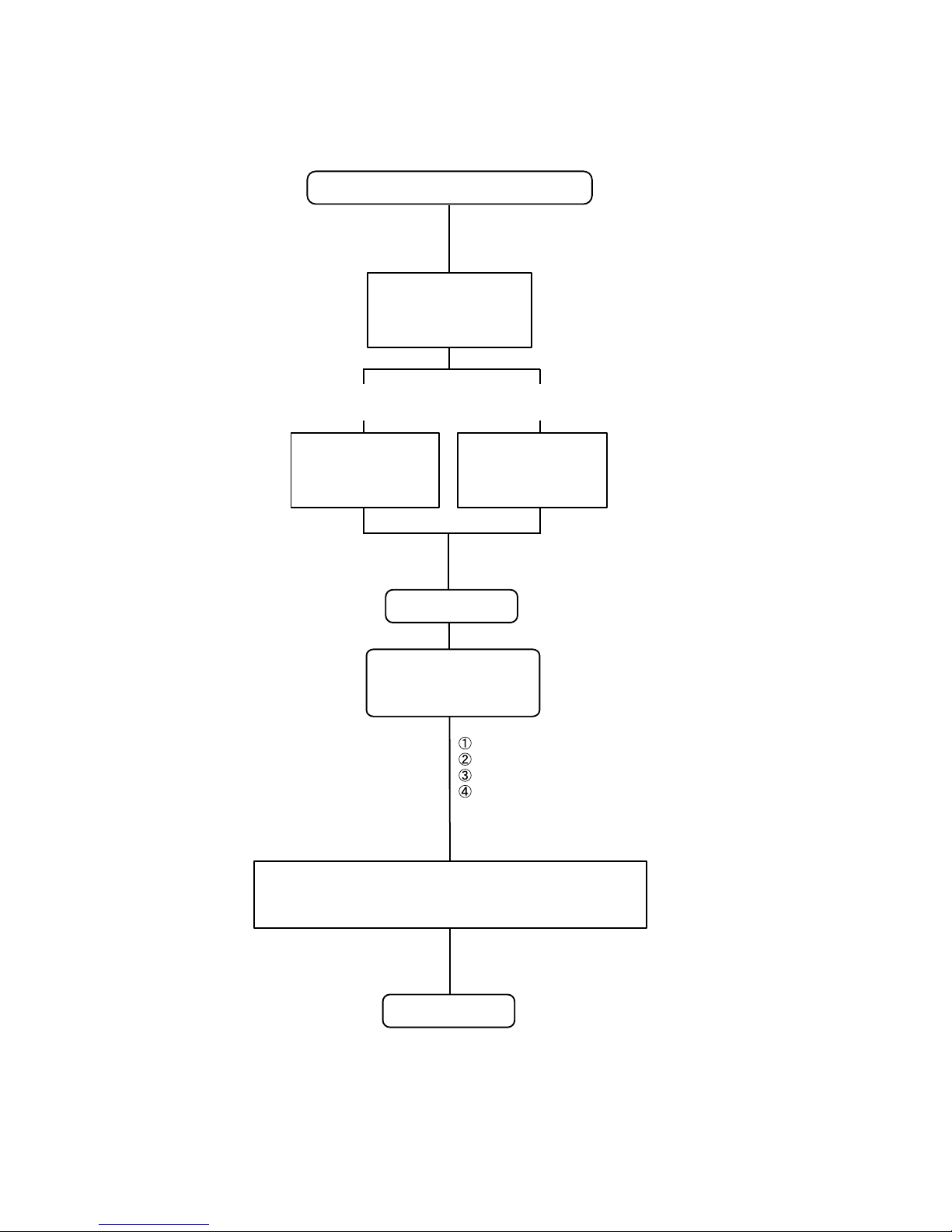
Defrost Flow Chart
The defrosting shall proceed by the integrating operation time and outdoor heat exchanger temperature as follows.
Heating operation start : Compressor ON
(Not defrosted for 6 or 10 minutes)
Compressor integrating
operation:
45 minutes and over
Outdoor temp. > 30.2°F
(-1°C)
Outdoor heat exchanger
temperature:
Below 17.6°F (-8°C)
=
Outdoor temp. < 30.2°F
(-1°C)
Outdoor heat exchanger
temperature:
Below 14°F (-10°C)
Defrost start
Defrost Indicator:
[Operation lamp]
7 sec ON / 1 sec OFF
Outdoor fan motor OFF
4-way valve OFF
Compressor ON
(Frequency : 92 Hz)
Outdoor heat exchanger temperature: Over 53.6°F (12°C)
or
Compressor ON time: Over 15 minutes
Defrost end
01-20
Page 24
23. VARIOUS PROTECTIONS
(1). DISCHARGE GAS TEMPERATURE OVERRISE PREVENSION CONTROL
The discharge gas thermosensor (discharge thermistor : Outdoor side) will detect discharge gas
temperature.
When the discharge temperature becomes higher than Temperature ,the compressor frequency
is decreased 20 Hz, and it continues to decrease the frequency for 20 Hz every 120 seconds until
the temperature becomes lower than Temperature .
When the discharge temperature becomes lower than Temperature ,the control of the control of the
compressor frequency is released.
When the discharge temperature becomes higher than Temperature ,the compressor is stopped
and the indoor unit LED starts blinking.
(Table 11 : Discharge Temperature Over Rise Prevension Control / Release Temperature)
Temperature
AOU24/36RML 230°F(110°C) 212°F(100°C) 239°F(115°C)
Temperature
(2). CURRENT RELEASE CONTROL
The compressor frequency is controlled so that the outdoor unit input current does not exceeds
the current limit value that was set up with the outdoor temperature.
The compressor frequency returns to the designated frequency of the indoor unit at the time
when the frequency becomes lower than the release value.
Temperature
(3). ANTI-FREEZING CONTROL (Cooling mode)
The compressor frequency decreases on cooling mode when the indoor heat exchanger
temperature sensor detects the temperature lower than 37.4°F (3°C).
Then, the anti-freezing control is released when it becomes higher than 42.8°F (6°C).
(Fig 7 : Anti-freezing Protection Operation / Release Temperature)
Indoor heat exchange
temperature
The compressor frequency is
37.4°F
(3°C)
42.8°F
(6°C)
46.4°F
(8°C)
decreased 10Hz every 120 seconds.
Hold
Compressor OFF : Hold
Compressor ON : Release of protection
Release of protection
(4). COOLING PRESSURE OVER RISE PROTECTION
When the outdoor unit heat exchange sensor temperature rises to
158.9°F (70.5°C) or greater,
the compressor is stopped and error display is indicated.
01-21
Page 25

(5). HIGH TEMPERATURE RELEASE CONTROL ( HEATING MODE )
On heating mode, the compressor frequency is controlled as following based on the
detection value of the indoor heat exchanger temperature sensor.
(Fig 8 : Heating Overload Protection Control)
Indoor heat exchange
temperature
Compressor is OFF
145.4°F
(63°C)
132.8°F
(56°C)
125.6°F
(52°C)
The compressor frequency is
decreased 10Hz every 60 seconds.
Hold
Compressor OFF :
Release of protection
Compressor ON :
The compressor frequency is
increased 10Hz every 60seconds.
01-22
Page 26

R410A
WALL MOUNTED / DUCT
CASSETTE type
INVERTER (MULTI)
2 . TROUBLE SHOOTING
Page 27
2. TROUBLESHOOTING
2-1 ERROR DISPLAY
2-1-1 INDOOR UNIT DISPLAY
For ASU9 - 18RMLQ
The OPERATION, TIMER, AIR CLEAN and COIL DRY lamps operate
as follows according to the error contents.
Error display
Error contents
Communication error
(Serial reverse transfer error)
Outdoor communication signal error
(Forward transfer signal error)
Communication error
(indoor unit remote control)
Room temperature thermistor error
Indoor heat exchanger temperature
thermistor (middle) error
Outdoor discharge pipe temperature
thermistor error
Outdoor heat exchanger temperature
thermistor error
Outdoor temperature thermistor error
OPERATION
(RED) (GREEN) (GREEN)
2 times
2 times
3 times
3 times
3 times
TIMER
2 times
3 times
4 times
5 times
8 times
2 times
3 times
2 times
3 times
4 times
AIR CLEAN
or QUIET
COIL DRY
(ORANGE)
Trouble
shooting
2
11
1
3
4
8
5
7
Heat sink temperature thermistor error
Compressor temperature thermistor error
2-way valve temperature thermistor error
3-way valve temperature thermistor error
Manual auto switch error
Power supply frequency detection error
VDD permanence stop protection
(Electric air clean)
Reverse-VDD permanence stop protection
(Electric air clean power supply circuit abnormal)
IPM error
CT error
Compressor rotor location cannot detect
(permanent stop)
Outdoor unit fan motor error
Connected indoor unit error
Main CPU-Sub CPU communication error
Indoor fan motor abnormal
Discharge temperature error
3 times
3 times
3 times 2 times
3 times 3 times
4 times
4 times
4 times
4 times
5 times
5 times
5 times
5 times
5 times
5 times
6 times
7 times
7 times
8 times
2 times
4 times
7 times
8 times
2 times
3 times
5 times
6 times
7 times
8 times
2 times
3 times
2 times
19
12
21
22
25
26
29
30
14
15
17
18
23
24
10
31
Exessive high pressure protection on cooling
Pressure switch error
Active filter module (AFM) error
Indoor EEPROM abnormal (Model No.)
0.5s ON / 0.5s OFF (Flash)
:
:
OFF
7 times
7 times
8 times
Continuous
blink
02-01
3 times
5 times
2 times
3 times
Continuous
blink
Continuous
blink
Continuous
blink
32
13
16
9
Page 28
For AUU9 - 18RML
The OPERATION, TIMER and FILTER lamps operate as follows according to the error contents.
Error contents
Communication error
(Serial reverse transfer error)
Outdoor communication signal error
(Forward transfer signal error)
Communication error
(Main PCB Display PCB)
Communication error
(Main PCB Display PCB)
Communication error
(indoor unit remote control)
Room temperature thermistor error
Indoor heat exchanger temperature
thermistor (middle) error
Water drain abnormal
Outdoor discharge pipe temperature
thermistor error
Outdoor heat exchanger temperature
thermistor error
Outdoor temperature thermistor error
Heat sink temperature thermistor error
Error display
OPERATION TIMER FILTER
(GREEN) (ORANGE) (RED)
2 times
3 times
4 times
5 times
6 times
7 times
8 times
2 times
2 times
2 times
3 times
3 times
2 times
3 times
6 times
2 times
3 times3 times
4 times3 times
7 times
Trouble
shooting
2
11
27
28
1
3
4
6
8
5
7
19
Compressor temperature thermistor error
2-way valve temperature thermistor error
3-way valve temperature thermistor error
Manual auto switch error
IPM error
CT error
Compressor rotor location cannot detect
(permanent stop)
Outdoor unit fan motor error
Connected indoor unit error
Main CPU-Sub CPU communication error
Indoor fan motor abnormal
Discharge temperature error
Exessive high pressure protection on cooling
4 way valve error operation
3 times
3 times
3 times
4 times
5 times
6 times
7 times
8 times
2 times
2 times
3 times5 times
5 times5 times
6 times5 times
7 times5 times
8 times5 times
2 times
3 times
2 times7 times
3 times7 times
4 times
2 times
3 times
12
21
22
25
14
15
17
18
23
24
10
31
32
35
Pressure switch error
Compressor temperature error
Indoor EEPROM abnormal error
0.5s ON / 0.5s OFF (Flash)
:
:
OFF
continuance
blink
02-02
5 times7 times
6 times7 times
continuance
blink
continuance
blink
13
33
9
Page 29
2-1-2 OUTDOOR UNIT DISPLAY
1. ERROR DISPLAY
Error Contents
Outdoor communication signal error
(Forward transfer signal error)
Outdoor discharge pipe temperature
thermistor error
Outdoor heat exchanger temperature
thermistor error
Outdoor temperature thermistor error
2-way valve temperature thermistor A error
2-way valve temperature thermistor B error
2-way valve temperature thermistor C error
2-way valve temperature thermistor D error
3-way valve temperature thermistor A error
3-way valve temperature thermistor B error
3-way valve temperature thermistor C error
3-way valve temperature thermistor D error
LED
AB C D
1 times blink
OFF
OFF OFF
OFF OFF
2 times blink
3 times blink
4 times blink
5 times blink
6 times blink
6 times blink
OFF
1 times blink
5 times blink
OFF
OFF
OFFOFF
OFF
1 times blink
OFF
OFFOFF
OFFOFF
OFFOFF
OFFOFF
OFFOFF
5 times blink
OFFOFFOFF
6 times blink
OFFOFFOFF
OFF
OFF
OFF
1 times blink
OFF
OFF
OFF
OFF
OFF
OFFOFFOFF
5 times blink
OFFOFF
OFFOFFOFF
OFF
6 times blink
Trouble
shooting
11
8
5
7
21
22
Compressor temperature thermistor error
Heat sink temperature thermistor error
Pressure switch 1 error
Pressure switch 2 error
Connected indoor unit error
IPM error
Compressor rotor location cannot detect
(permanent stop)
Compressor Start-up error
(permanent stop)
Outdoor unit fan motor error
Main CPU - sub CPU communication error
7 times blink
8 times blink
9 times blink
10 times blink
11 times blink
12 times blink
13 times blink
14 times blink
15 times blink
17 times blink
OFF
OFF
OFF
OFF
OFF
OFF
OFF
OFF
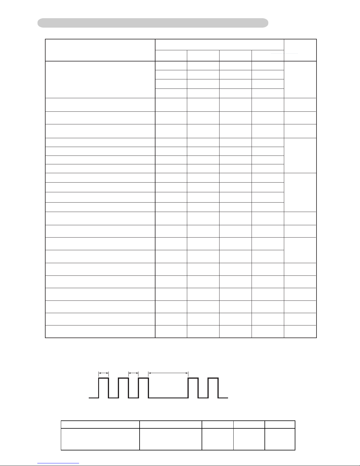
2. ERROR DISPLAY METHOD
Outdoor LED Blink (1 to 18 times) 0.5sec ON / 0.5sec OFF blinking
0.5sec 0.5sec 2sec
ON
OFF
OFF
OFF
OFF
OFF
OFF
OFF
OFF
OFFOFF
OFFOFF
OFF
OFF
OFF
OFF
OFF
OFF
OFF
OFF
OFF
OFF
12
19
13
23
14
17
20
18
24
OFF
3. NORMAL OPERATION DISPLAY
Operation
Normal operation
㪣㪜㪛㩷㪘 㪣㪜㪛㩷㪙 㪣㪜㪛㩷㪚 㪣㪜㪛㩷㪛
Continuously lighting
02-03
䌏䌆䌆䌏䌆䌆 䌏䌆䌆
Page 30
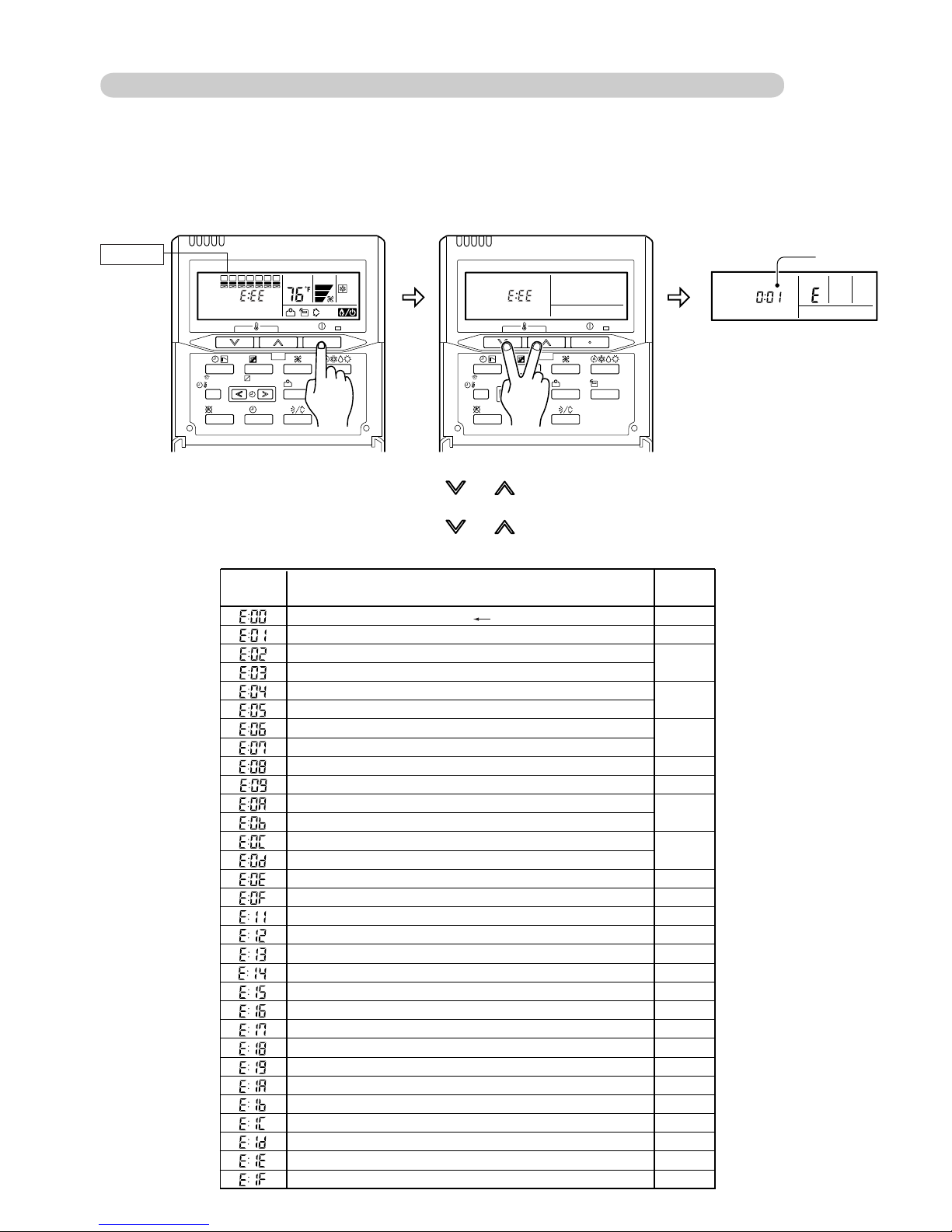
2-1-3 WIRED REMOTE CONTROLLER DISPLAY
For ARU9-18RML (AR-3TA)
1. SELF - DIAGNOSIS
When the error indication "E:EE" is displayed, inspection of the air conditioning system is necessary.
Please consult authoilzed servise personnel.
Run [Self-Diagnosis] if [E:EE] flashes on the clock display of the remote controller.
Display
SUMOTUWETH FR
CLOCK ADJUST
SET BACK
DELETE SET
DAY
DAY OFF
SA
ENERGY
SAVE
1. Stop the air conditioner operation.
2. Press the SET TEMPERATURE buttons and simultaneously for 5 seconds or more
to start the self-diagnosis.
3. Press the SET TEMPERATURE buttons and simultaneously for 5 seconds or more
or there is no key input for 20 seconds to stop the self-diagnosis.
Error code
Communication error (indoor unit remote control)
Communication error (Serial reverse transfer error)
Room temperature thermistor open
Room temperature thermistor short-circuited
Indoor heat exchanger temperature thermistor open
Indoor heat exchanger temperature thermistor short-circuited
Outdoor heat exchanger temperature thermistor open
Outdoor heat exchanger temperature thermistor short-circuited
Power supply frequency detection error
Water drain abnormal
Outdoor temperature thermistor open
Outdoor temperature thermistor short-circuited
Outdoor discharge pipe temperature thermistor open
Outdoor discharge pipe temperature thermistor short-circuited
Heat sink temperature thermistor error
Discharge pipe temperature thermistor error
Indoor EEPROM abnormal (Model No.)
Indoor fan motor abnormal
Outdoor communication signal error (Forward transfer signal error)
Exessive high pressure protection on cooling
Compressor temperature thermistor error
Pressure switch error
IPM error
CT error
Active Filter Module (AFM) error
Compressor rotor location cannot detect
Outdoor unit fan motor error
Main CPU - sub CPU communication error
2-way valve temperature thermistor error
3-way valve temperature thermistor error
Connected indoor unit error
Error contents
02-04
CLOCK ADJUST
SET BACK
DELETE SET
DAY
DAY OFF
SET
ENERGY
SAVE
THERMO
SENSOR
Trouble
shooting
1
2
3
4
5
26
6
7
8
19
8
9
10
11
32
12
13
14
15
16
17
18
24
21
22
23
Error code
SUMOTUWETH FR
SA
Ex. Self-diagnosis
Page 31

2. ERROR CODE HISTORY DISPLAY
Up to 16 memorized error codes may be displayed for the indoor unit connected to the remote controller.
1. Stop the air conditioner operation.
2. Press the SET TEMPERATURE buttons , simultaneously for 5 seconds or more to
start the self-diagnosis.
Error code
Error history number
DAY
SUMOTUWETH FR
3. Press the SET TEMPERATURE button to select the error history number.
SA
Lower
DAY
Raise
01234 567
FEdcb A9 8
ı
ı
4. Press the SET TEMPERATURE buttons , simultaneously for 3 seconds or more
or there is no key input for 60 seconds to stop the display.
02-05
Page 32

For AUU09-18RML (AR-6TC)
1. SELF - DIAGNOSIS
When "EE" in Temperature Display is displayed, inspection of the air conditioning system is necessary.
Please consult authoilzed servise personnel.
Unit number (usually 0)
Error code
SU MOTUWETH FR SA
ex. Self-diagnosis check
Error code
Error contents
Communication error (indoor unit remote control)
Communication error (Serial reverse transfer error)
Room temperature sensor error
Indoor heat exchanger temperature sensor error
Outdoor heat exchanger temperature sensor(outlet) error
Water drain abnormal
Outdoor temperature sensor error
Outdoor discharge pipe temperature sensor error
Heatsink temperature thermistor error
Discharge temperature error
Indoor EEPROM abnormal
Indoor fan motor abnormal
Outdoor communication signal error (Forward transfer signal error)
Compressor temperature sensor error
Pressure switch error
IPM error
CT error
Active filter module error
Compressor rotor location cannot detect (permanent stop)
Outdoor unit fan motor error
2-way valve temperature thermistor error
3-way valve temperature thermistor error
Main CPU - sub CPU communication error
Connected indoor unit error
Indoor manual auto switch error
Exessive high pressure protection on cooling
Communication error (Main PCB Display PCB)
Communication error (Main PCB Display PCB)
4-way valve error
Trouble
shooting
1
2
3
4
5
6
7
8
19
31
9
10
11
12
13
14
15
16
17
18
21
22
24
23
25
32
27
28
35
If “CO” appears in the unit number display, there is a remote controller error.
Refer to the installation instruction sheet included with the remote controller.
02-06
Page 33

2. ERROR CODE HISTORY DISPLAY
Up to 16 memorized error codes may be displayed for the indoor unit connected to the remote controller.
1. Stop the air conditioner operation.
2. Press the SET TEMPERATURE buttons , and the START/STOP button simultaneously
for 5 seconds or more to start the self-diagnosis.
DAY
SUMOTUWETH FR
SA
3. Press the START/STOP button.
Error code
Error history number
DAY
SUMOTUWETH FR
SA
4. Press the SET TEMPERATURE button to select the error history number.
Lower
DAY
Raise
01234 567
FEdcbA98
ı
ı
5. Press the SET TEMPERATURE buttons , and START/STOP button simultaneously
for 5 seconds or more or there is no key input for 20 seconds to stop the display.
02-07
Page 34

2-2 TROUBLE SHOOTING WITH ERROR CODE
Trouble shooting 1
INDOOR UNIT Error Method:
Indicate or Display:
Refer to error code table.
Communication Error
(Indoor unit Remote control)
Detective Actuators:
Indoor unit controller PCB circuit
Wired Remote Control
Detective details:
When the indoor unit cannot receive the signal from Wired Remote
more than 10seconds after power ON, or the indoor unit cannot receive
the signal more than 1minute during normal operation.
Forecast of Cause:
1. Terminal connection abnormal 2. Wired Remote Control failure 3. Control PCB failure (AS, AR)
Check Point 1 : Check the connection of terminal
After turning off the power, check & correct the followings.
Check the connection of terminal between remote control and Indoor unit,
and check if there is a disconnection of the cable.
OKOK
Check Point 2 : Check Remote Control and Control PCB
Main PCB (AU)
Check Voltage at CN10 (AS type) of Control PCB. (Power supply to Remote Control)
CN17 (AR type)
CN14 (AU type)
>> If it is DC12V, Remote Control is failure. (
>> If it is DC 0V,
Main PCB is failure. (Check Remote Control once again) >> Replace
Upon correcting the removed connector or mis-wiring, reset the power.
Control PCB is failure. (Check Remote Control once again) >> Replace Control PCB (AS, AR)
Control PCB is normal) >> Replace Remote Control
Main PCB (AU)
02-08
Page 35

Trouble shooting 2
OUTDOOR UNIT Error Method:
Communication Error
(Serial Reverse Transfer Error)
Indicate or Display:
Refer to error code table.
Detective Actuators:
Detective details:
Outdoor Unit Main PCB Circuit
Active Filter Module
Forecast of Cause:
1. Connection failure 2. External cause 3. Main PCB failure 4. Active Filter Module failure
Check Point 1-1 : Reset the power and operate
Does Error indication show again?
YESYES
Check Point 2 : Check Connection
Check any loose or removed connection line of
Indoor unit and Outdoor unit.
>> If there is an abnormal condition, correct it by
referring to Installation Manual or Data &
Technical Manual.
Check connection between Outdoor Unit Main PCB
and Filter PCB.
(If there is loose connector or open cable)
When the indoor unit cannot receive the serial signal from Outdoor unit
more than 10seconds.
NO
Check Point 1-2:
Check external cause such as noise
Check the complete insulation of the grounding.
Check if there is any equipment that causes harmonic wave
near the power cable (Neon light bulb or any electronic
equipment which causes harmonic wave).
OK
Check Point 3 : Check the voltage of power supply
Check the voltage of power supply
>> Check if AC208 - 230V appears at Outdoor Unit Terminal L - N.
OK
Check Point 4 : Check Serial Signal (Reverse Transfer Signal)
Check Serial Signal (Reverse Transfer Signal)
>> Check if Indicated value swings between AC70V and AC130V at Outdoor Unit Terminal N - 3.
>> If it is abnormal, Check Active Filter Module. (PARTS INFORMATION 3)
>>If Active Filter Module is abnormal, replace it.
>>If Active Filter Module is normal, replace Main PCB.
WHITE
BLACK
RED
N
L
3
+
-
02-09
Page 36

Trouble shooting 3
INDOOR UNIT Error Method:
INDOOR UNIT
Room Temperature Thermistor Error
Indicate or Display:
Refer to error code table.
Detective Actuators:
Indoor Unit Control PCB(AS, AR) ,
Main PCB(AU) or Room Temperature
Detective details:
When Room Temperature Thermistor open or short-circuit is
detected at power ON.
Thermistor
Forecast of Cause :
1. Connector connection failure 2.Thermistor failure 3. Control PCB (AS,AR),MainPCB (AU) failure
Check Point 1 : Check connection of Connector
Check if connector is removed.
Check erroneous connection.
Check if thermistor cable is open.
>>Upon correcting the removed connector or mis-wiring, reset the power.
OK
Check Point 2 : Check Point 2 : Remove connector and check Thermistor resistance value
Thermistor Characteristics (Approx. value)
Temperature
32°F
(0°C)
41°F
(5°C)
50°F
(10°C)
59°F
(15°C)
68°F
(20°C)
77°F
(25°C)
10.012.515.820.225.933.6Resistance Value (k )
86°F
(30°C)
8.04
95°F
(35°C)
6.51
Temperature
104°F
(40°C)
113°F
(45°C)
122°F
(50°C)
3.594.355.30Resistance Value (k )
If Thermistor is either open or shorted, replace it and reset the power.
OK
Check Point 3 : Check Point 3 : Check voltage of Controller PCB (DC5.0V)
Make sure circuit diagram of indoor unit and check terminal voltage at Thermistor (DC5.0V)
GRAY
1
GRAY
2
BLACK
1
BLACK
2
CN8 CN7 (AR)
CN8 CN5 (AU)
CN5 CN6 (AS)
If the voltage does not appear, replace Controller PCB(AS, AR), Main PCB(AU).
THERMISTOR
(PIPE TEMP.)
THERMISTOR
(ROOM TEMP.)
02-10
Page 37

Trouble shooting 4
INDOOR UNIT Error Method:
INDOOR UNIT
Indoor Heat Exchanger Temperature
Thermistor Error
Indicate or Display:
Refer to error code table.
Detective Actuators:
Indoor Unit Control PCB (AS, AR) ,
Main PCB (AU) or Room Temperature
Detective details:
When Heat Exchanger Temperature Thermistor open or short-circuit is
detected at power ON.
Thermistor
Forecast of Cause :
1. Connector connection failure 2.Thermistor failure 3. Control PCB (AS,AR),MainPCB (AU) failure
Check Point 1 : Check connection of Connector
Check if connector is removed.
Check erroneous connection.
Check if thermistor cable is open.
>>Upon correcting the removed connector or mis-wiring, reset the power.
OKOK
Check Point 2 :
Check Point 2 : Remove connector and check Thermistor resistance value
Thermistor Characteristics (Approx. value)
Temperature
32°F
(0°C)
41°F
(5°C)
50°F
(10°C)
59°F
(15°C)
68°F
(20°C)
77°F
(25°C)
49.762.980.3103134176Resistance Value (k )
86°F
(30°C)
39.6
95°F
(35°C)
31.7
Temperature
104°F
(40°C)
113°F
(45°C)
122°F
(50°C)
17.120.825.6Resistance Value (k )
If Thermistor is either open or shorted, replace it and reset the power.
OK
Check Point 3 : Check voltage of Controller PCB (DC5.0V)
Make sure circuit diagram of indoor unit and check terminal voltage at Thermistor (DC5.0V)
GRAY
1
GRAY
2
BLACK
1
BLACK
2
CN8 CN7 (AR)
CN8 CN5 (AU)
CN5 CN6 (AS)
If the voltage does not appear, replace Controller PCB(AS, AR), Main PCB(AU).
THERMISTOR
(PIPE TEMP.)
THERMISTOR
(ROOM TEMP.)
02-11
Page 38

Trouble shooting 5
OUTDOOR UNIT Error Method:
Outdoor Heat Exchanger Temperature
Thermistor Error
Indicate or Display:
Refer to error code table.
Detective Actuators:
Outdoor Unit Main PCB Circuit
Heat Exchanger Temperature Thermistor
Detective details:
When Heat Exchanger Temperature Thermistor open or short-circuit is
detected at power ON or while running the compressor.
Forecast of Cause :
1. Connector connection failure 2.Thermistor failure 3. Main PCB failure
Check Point 1 : Check connection of Connector
Check if connector is removed.
Check erroneous connection.
Check if thermistor cable is open.
>>Upon correcting the removed connector or mis-wiring, reset the power.
OKOK
Check Point 2 :
Check Point 2 : Remove connector and check Thermistor resistance value
Thermistor Characteristics (Approx. value)
Temperature
14°F
(-10°C)
23°F
(-5°C)
32°F
(0°C)
41°F
(5°C)
50°F
(10°C)
59°F
(15°C)
7.679.7312.416.120.927.5Resistance Value (k )
68°F
(20°C)
6.10
77°F
(25°C)
4.89
86°F
(30°C)
3.95
If Thermistor is either open or shorted, replace it and reset the power.
OKOK
Check Point 3 :
Check Point 3 : Check voltage of Main PCB (DC5.0V)
Make sure circuit diagram of outdoor unit and check terminal voltage at Thermistor (DC5.0V)
THERMISTOR
BLUE
(PIPE)
BLACK
THERMISTOR
(DISCHARGE)
BROWN
1 21 21 21 21 2
THERMISTOR
THERMISTOR
(HEAT SINK)
(COMPRESSOR)
BLACK
THERMISTOR
(OUTDOOR)
BROWN
CN25 CN26 CN23 CN22 CN21
If the voltage does not appear, replace Main PCB.
DC
02-12
Page 39

Trouble shooting 6
INDOOR UNIT Error Method:
Water Drain Abnormal
Indicate or Display:
Refer to error code table.
Detective Actuators:
Indoor Unit Main PCB Circuit
Detective details:
When Float Switch is ON for more than 3 minutes.
Float Switch
Forecast of Cause :
1. Float Switch failure 2. Shorted connector/ wire 3. Main PCB failure
Check Point 1 : Check Float Switch
Check operation of float switch. (any blocking by dust, etc.)
Remove Float switch and check ON/OFF switching operation
by using a meter.
>>If Float switch is detective, replace it.
OKOK
Check Point 2 : Check Point 2 : Check Connector (CN9) / Wire
Check loose contact of CN9 /shorted wire (pinched wire).
>>Replace Float switch if the wire is abnormal
ONON OFFOFF
OKOK
Check Point 3 : Replace Main PCB
If Check Point 1 & 2 do not improve the symptom, change Controller PCB.
02-13
Page 40

Trouble shooting 7
OUTDOOR UNIT Error Method:
INDOOR UNIT
Outdoor Temperature
Thermistor Error
Indicate or Display:
Refer to error code table.
Detective Actuators:
Outdoor Unit Main PCB Circuit
Outdoor Temperature Thermistor
Detective details:
When Outdoor Temperature Thermistor open or short-circuit is
detected at power ON or while running the compressor.
Forecast of Cause :
1. Connector connection failure 2.Thermistor failure 3. Main PCB failure
Check Point 1 : Check connection of Connector
Check if connector is removed.
Check erroneous connection.
Check if thermistor cable is open.
>>Upon correcting the removed connector or mis-wiring, reset the power.
OKOK
Check Point 2 :
Check Point 2 : Remove connector and check Thermistor resistance value
Thermistor Characteristics (Approx. value)
Temperature
Temperature
- 4°F
(-20°C)
86°F
(30°C)
14°F
(-10°C)
104°F
(40°C)
23°F
(-5°C)
122°F
(50°C)
32°F
(0°C)
140°F
(60°C)
41°F
(5°C)
158°F
(70°C)
50°F
(10°C)
59°F
(15°C)
16.1
68°F
(20°C)
12.620.726.935.246.662.3115Resistance Value (k )
5.187.97
If Thermistor is either open or shorted, replace it and reset the power.
3.45 2.36 1.65Resistance Value (k )
OKOK
Check Point 3 :
Check Point 3 : Check voltage of Main PCB (DC5.0V)
Make sure circuit diagram of outdoor unit and check terminal voltage at Thermistor (DC5.0V)
THERMISTOR
BLUE
(PIPE)
BLACK
THERMISTOR
(DISCHARGE)
BROWN
1 21 21 21 21 2
THERMISTOR
THERMISTOR
(HEAT SINK)
(COMPRESSOR)
BLACK
THERMISTOR
(OUTDOOR)
BROWN
CN25 CN26 CN23 CN22 CN21
If the voltage does not appear, replace Main PCB.
02-14
Page 41

Trouble shooting 8
OUTDOOR UNIT Error Method:
INDOOR UNIT
Outdoor Discharge Pipe Temperature
Thermistor Error
Indicate or Display:
Refer to error code table.
Detective Actuators:
Outdoor Unit Main PCB Circuit
Discharge Pipe Temperature Thermistor
Detective details:
When Discharge Pipe Temperature Thermistor open or short-circuit
is detected at power ON or while running the compressor.
Forecast of Cause :
1. Connector connection failure 2.Thermistor failure 3. Main PCB failure
Check Point 1 : Check connection of Connector
Check if connector is removed.
Check erroneous connection.
Check if thermistor cable is open.
>>Upon correcting the removed connector or mis-wiring, reset the power.
OKOK
Check Point 2 :
Check Point 2 : Remove connector and check Thermistor resistance value
Thermistor Characteristics (Approx. value)
Temperature
32°F
(0°C)
41°F
(5°C)
50°F
(10°C)
59°F
(15°C)
68°F
(20°C)
86°F
(30°C)
41.164.581.8105135176Resistance Value (k )
Temperature
158°F
(70°C)
176°F
(80°C)
194°F
(90°C)
212°F
(100°C)
248°F
(120°C)
284°F
(140°C)
104°F
(40°C)
320°F
(160°C)
122°F
(50°C)
18.126.9
356°F
(180°C)
140°F
(60°C)
12.5
1.211.983.434.616.318.78Resistance Value (k )
If Thermistor is either open or shorted, replace it and reset the power.
0.77
0.51
OKOK
Check Point 3 :
Check Point 3 : Check voltage of Main PCB (DC5.0V)
Make sure circuit diagram of outdoor unit and check terminal voltage at Thermistor (DC5.0V)
THERMISTOR
BLUE
(PIPE)
BLACK
THERMISTOR
(DISCHARGE)
BROWN
1 21 21 21 21 2
THERMISTOR
THERMISTOR
(HEAT SINK)
(COMPRESSOR)
BLACK
THERMISTOR
(OUTDOOR)
BROWN
CN25 CN26 CN23 CN22 CN21
If the voltage does not appear, replace Main PCB.
02-15
Page 42

Trouble shooting 9
INDOOR UNIT Error Method:
Indoor EEPROM abnormal
(Model No.)
Indicate or Display:
Indicate or Display:
Refer to error code table.
Detective Actuators:
Indoor Unit Control PCB (AS,AR),
Main PCB (AU) circuit
Detective details:
When the model information being read from EEPROM has
an apparent error.
Forecast of Cause:
1. External cause 2. Defective connection of electric components 3. Control PCB failure (AS,AR),
Main PCB (AU)
Check Point 1-1 : Reset Power Supply and operate
Does Error indication show again?
YESYES
Check Point 2 :
Check Indoor Unit electric components
Check all connectors.
(loose connector or incorrect wiring)
Check any shortage or corrosion on PCB.
Check Point 3 : Replace Controller PCB
Change Control PCB (AS,AR), Main PCB (AU).
NO
Check Point 1-2 :
Check external cause at Indoor and Outdoor
(Voltage drop or Noise)
Instant drop : Check if there is a large load electric apparatus
in the same circuit.
Momentary power failure : Check if there is a defective contact
or leak current in the power supply
circuit.
Noise : Check if there is any equipment causing harmonic
wave near electric line.(Neon bulb or electric
equipment that may cause harmonic wave)
Check the complete insulation of grounding.
Note : EEPROM
EEPROM(Electronically Erasable and
Programmable Read Only Memory) is a nonvolatile memory which keeps memorized
information even if power is turned off. It can
change the contents electronically.
To change the contents, it uses higher
voltage than normal, and it can not change a
partial contents. (Rewriting shall be done
upon erasing the all contents.)
There is a limit in a number of rewriting.
02-16
Page 43

Trouble shooting 10
INDOOR UNIT Error Method:
Indoor Fan Motor abnormal
Indicate or Display:
Refer to error code table.
Detective Actuators:
Indoor Unit Control PCB (AS,AR),
Main PCB, Power PCB (AU) Circuit.
Indoor Fan Motor
Detective details:
When the condition that actual frequency of Indoor Fan is below 1/3
of target frequency is continued more than 56 seconds.
Or the condition of fan speed is 0rpm is continued more than 56 seconds.
Forecast of Cause:
1. Fan rotation failure 2. Motor protection by surrounding temperature rise 3. Control PCB (AS,AR),
Main PCB ,Power PCB (AU)
Check Point 1 : Check rotation of Fan
Rotate the fan by hand when operation is off.
(Check if fan is caught, dropped off or locked motor)
>>If Fan or Bearing is abnormal, replace it.
OK
Check Point 2 : Check ambient temp. around motor
Check excessively high temperature around the motor.
(If there is any surrounding equipment that causes heat)
>>Upon the temperature coming down, restart operation.
OK
Check Point 3 : Replace Control PCB
If Check Point 1,2 do not improve the symptom, change Control PCB (AS,AR),
Main PCB ,Power PCB (AU)
02-17
Page 44

Trouble shooting 11
INDOOR UNIT Error Method:
Outdoor Communication Signal Error
(Forward Transfer Signal Error)
Indicate or Display:Indicate or Display:
Refer to error code table.
Detective Actuators:
Indoor Unit Control PCB (AS,AR),
Main PCB, Power PCB (AU) Circuit
Forecast of Cause:
1. Connection failure 2. External cause 3. Controll PCB (AS,AR), Main PCB, Power PCB (AU) failure
Check Point 1-1 : Reset the power
Does Error indication reappear?
YESYES
Check Point 2 : Check Connection
Check any loose or removed connection line of
Indoor unit and Outdoor unit.
>> If there is an abnormal condition, correct it by
referring to Installation Manual or Data &
Technical Manual.
Check connection between Indoor Unit Control PCB
and Filter PCB.(AR)
(If there is loose connector or open cable)
Check connection between Indoor Unit Main PCB
and Power PCB.(AU)
(If there is loose connector or open cable)
Detective details:
When the outdoor unit cannot receive the serial signal from Indoor unit
more than 10seconds.
NO
Check Point 1-2:
Check external cause such as noise
Check the complete insulation of the grounding.
Check if there is any equipment that causes harmonic wave
near the power cable (Neon light bulb or any electronic
equipment which causes harmonic wave).
OK
Check Point 3 : Check the voltage of power supply
Check the voltage of power supply
>> Check if AC208 - 230V appears at Outdoor Unit Terminal L - N.
OK
Check Point 4 : Check Serial Signal (Forward Transfer Signal)
Check Serial Signal (Forward Transfer Signal)
>> Check if Indicated value swings between AC70V and AC130V at Outdoor Unit Terminal N - 3.
>> If it is abnormal, Controller PCB is failure. >> Replace Control PCB (AS,AR),
Main PCB , Power PCB (AU)
WHITE
BLACK
RED
N
L
3
+
-
02-18
Page 45

Trouble shooting 12
OUTDOOR UNIT Error Method:
Compressor Temperature
Thermistor Error
Indicate or Display:
Refer to error code table.
Detective Actuators:
Outdoor Unit Main PCB Circuit
Compressor Temperature Thermistor
Detective details:
When Compressor Temperature Thermistor open or short-circuit is
detected at power ON or while running the compressor.
Forecast of Cause :
1. Connector connection failure 2. Thermistor failure 3. Main PCB failure
Check Point 1 : Check connection of Connector
Check if connector is removed.
Check erroneous connection.
Check if thermistor cable is open.
>>Upon correcting the removed connector or mis-wiring, reset the power.
OKOK
Check Point 2 :
Check Point 2 : Remove connector and check Thermistor resistance value
Thermistor Characteristics (Rough value)
Temperature
32°F
(0°C)
41°F
(5°C)
50°F
(10°C)
59°F
(15°C)
68°F
(20°C)
86°F
(30°C)
41.164.581.8105135176Resistance Value (k )
Temperature
158°F
(70°C)
176°F
(80°C)
194°F
(90°C)
212°F
(100°C)
248°F
(120°C)
284°F
(140°C)
104°F
(40°C)
320°F
(160°C)
122°F
(50°C)
18.126.9
356°F
(180°C)
140°F
(60°C)
12.5
1.211.983.434.616.318.78Resistance Value (k )
If Thermistor is either open or shorted, replace it and reset the power.
0.77
0.51
OKOK
Check Point 3 :
Check Point 3 : Check voltage of Main PCB (DC5.0V)
Make sure circuit diagram of outdoor unit and check terminal voltage at Thermistor (DC5.0V)
THERMISTOR
BLUE
(PIPE)
BLACK
THERMISTOR
(DISCHARGE)
BROWN
1 21 21 21 21 2
THERMISTOR
THERMISTOR
(HEAT SINK)
(COMPRESSOR)
BLACK
THERMISTOR
(OUTDOOR)
BROWN
CN25 CN26 CN23 CN22 CN21
If the voltage does not appear, replace Main PCB.
02-19
Page 46

Trouble shooting 13
OUTDOOR UNIT Error Method:
INDOOR UNIT
Pressure Switch Error
Indicate or Display:
Refer to error code table.
Detective Actuators:
Outdoor Unit Main PCB Circuit
Pressure Switch
Detective details:
When pressure switch open is detected in 10 seconds
after the power is turned on.
Forecast of Cause :
1. Connector connection failure 2. Pressure Switch failure 3. Main PCB failure
Check Point 1 : Reset Power Supply and operate
Does abnormal LED indication show again?
NONO
YESYES
Check Point 3 : Check Point 2 : Check voltage of Main PCB (DC5.0V)
Make sure circuit diagram of outdoor unit and check terminal voltage
at Pressure Switch. (DC5.0V)
PRESSURE SWITCH 1
RED
1
CN37
RED
2
PRESSURE SWITCH 2
RED
1
CN36
If the voltage does not appear, replace Main PCB.
RED
2
OK
Check Point 3 : Check Pressure Switch
Check if connector is loose or cable is open.
>> If no abnormal connection is found,
replace Pressure Switch.
After replacing Pressure Switch, check operating
condition and pressure in operation.
OK
Check Point 4 : Check High Pressure Protection on cooling
Check Excessive high pressure protection on cooling.
(Refer to Trouble shooting 31)
02-20
Page 47

Trouble shooting 14
OUTDOOR UNIT Error Method:
IPM error
Indicate or Display:
Refer to error code table.
Detective Actuators:
Outdoor Unit Main PCB Circuit
Compressor
Detective details:
When more than normal operating current to IPM in Main PCB flows,
the compressor stops.
After the compressor restarts, if the same operation is repeated within 40sec,
the compressor stops again.
If and repeats 5 times, the compressor stops permanently.
Forecast of Cause :
1. Defective connection of electric components 2. Outdoor Fan Operation failure
3. Outdoor Heat Exchanger clogged 4. Compressor failure 5. Main PCB failure
Check Point 1 : Check connections of Outdoor Unit Electrical Components
Check if the terminal connection is loose.
Check if connector is removed.
Check erroneous connection.
Check if cable is open.
>>Upon correcting the removed connector or mis-wiring, reset the power.
OK
Check Point 2 : Check Outdoor Fan, Heat Exchanger
Is there anything obstructing the air distribution circuit?
Is there any clogging of Outdoor Heat Exchanger?
Is the Fan rotating by hand when operation is off ?
>> If the Fan Motor is locked, replace it.
Check Outdoor Fan Motor. (Refer to Trouble shooting 18)
>> If the Fan Motor is failure, replace it.
OK
Check Point 3 : Check Compressor
Check Compressor.
(PARTS INFORMATION 2)
OKOK
Check Point 4 : Replace Main PCB
If Check Point 1, 2, 3 do not improve the symptom, change Main PCB.
02-21
Page 48

Trouble shooting 15
OUTDOOR UNIT Error Method:
CT error
Indicate or Display:
Refer to error code table.
Detective Actuators:
Outdoor Unit Main PCB Circuit
Outdoor Unit Filter PCB Circuit
(Input current sensor unit)
Detective details:
When Input Current Sensor has detected lower than 0A
while Inverter Compressor is operating at higher than 50Hz,
after 1minute upon starting the Compressor.
(Except during the defrost operation)
Forecast of Cause :
1. Defective connection of electric components 2. External cause 3. Filter PCB failure 4. Main PCB failure
Check Point 1-1 : Reset Power Supply and operate
Does Error indication show again?
NO
YES
Check Point 2 :
Check connections of Outdoor Unit Electrical Components
Check if the terminal connection is loose.
Check if connector is removed.
Check erroneous connection.
Check if cable is open.
>>Upon correcting the removed connector or mis-wiring,
reset the power.
OK
Check Point 1-2 :
Check external cause at Indoor and Outdoor
(Voltage drop or Noise)
Instant drop : Check if there is a large load electric
apparatus in the same circuit.
Momentary power failure : Check if there is a defective
contact or leak current in the
power supply circuit.
Noise : Check if there is any equipment causing harmonic
wave near electric line.(Neon bulb or electric
equipment that may cause harmonic wave)
Check the complete insulation of grounding.
Check Point 3 : Check Filter PCB and Main PCB
Check DC voltage of CN1 (between 2 (Brown) and 3 (Red)) on Filter PCB.
>> After 40seconds upon starting the Compressor,
If it is higher than 0.2V, Main PCB is failure. (Filter PCB is normal) >> Replace Main PCB
>> If it is lower than 0.2V, Filter PCB is failure. >> Replace Filter PCB
If it does not improve the symptom, change Main PCB.
02-22
Page 49
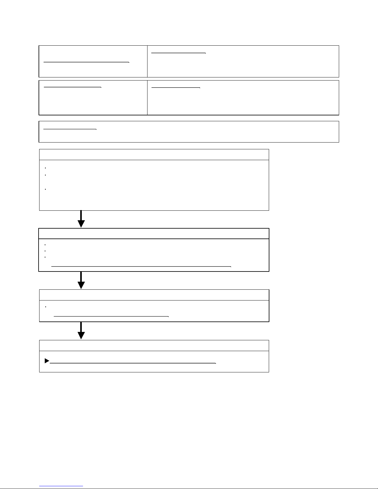
Trouble shooting 16
OUTDOOR UNIT Error Method:
INDOOR UNIT
Active Filter Module (AFM) error
Indicate or Display:
Refer to error code table.
Detective Actuators:
Outdoor Unit Main PCB Circuit
Active Filter Module
Detective details:
When inverter input DC voltage is higher than 467V or
lower than 237V.
When a momentary power cut off occurred on low voltage.
Forecast of Cause :
1. External cause 2. Connector connection failure 3. Active Filter Module failure˴㧠. Main PCB failure
Check Point 1 : Check external cause at Indoor and Outdoor (Voltage drop or Noise)
Instant drop : Check if there is a large load electric apparatus in the same circuit.
Momentary power failure : Check if there is a defective contact or leak current
in the power supply circuit.
Noise : Check if there is any equipment causing harmonic wave near electric line.
(Neon bulb or electric equipment that may cause harmonic wave)
Check the complete insulation of grounding.
OKOK
Check Point 2 : Check connection of Connector
Check if connector is removed.
Check erroneous connection.
Check if cable is open.
>>Upon correcting the removed connector or mis-wiring, reset the power.
OKOK
Check Point 3 : Check Active Filter Module
Check Active Filter Module. (PARTS INFORMATION 3)
>>If Active Filter Module is abnormal, replace it.
OKOK
Check Point 4 : Replace Main PCB
If Check Point 1, 2 do not improve the symptom, change Main PCB.
02-23
Page 50

Trouble shooting 17
OUTDOOR UNIT Error Method:
Compressor rotor location cannot detect
(Permanent Stop)
Indicate or Display:
Refer to error code table.
Detective Actuators:
Outdoor Unit Main PCB Circuit
Detective details:
While running the compressor, if the detected rotor location is out of
phase with actual rotor location more than 90 degrees,
the compressor stops.
After the compressor restarts, if the same operation is repeated
within 40sec, the compressor stops again.
If and repeats 5 times, the compressor stops permanently.
Forecast of Cause :
1. Defective connection of electric components 2. Main PCB failure
Check Point 1 : Check connection of around the Compressor components
For Compressor Terminal, Main PCB
Check if connector is removed.
Check erroneous connection.
Check if cable is open.
(Refer to PARTS INFORMATION 2)
>>Upon correcting the removed connector or mis-wiring, reset the power.
OKOK
Check Point 2 : Replace Main PCB
If Check Point 1 do not improve the symptom, change Main PCB.
02-24
Page 51
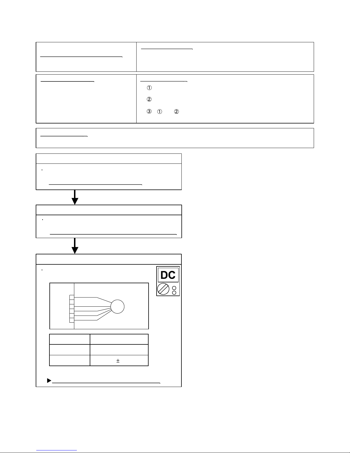
Trouble shooting 18
OUTDOOR UNIT Error Method:
Outdoor Unit Fan Motor Error
Indicate or Display:
Refer to error code table.
Detective Actuators:
Outdoor Unit Main PCB Circuit
Outdoor Fan Motor
Detective details:
When outdoor fan rotation speed is less than 100rpm in 20 seconds
after fan motor starts, fan motor stops.
After fan motor restarts, if the same operation within 60sec is repeated
3 times in a row, compressor and fan motor stops.
If and repeats 5 times in a row, compressor and fan motor stops
permanently.
Forecast of Cause:
1. Fan rotation failure 2. Motor protection by surrounding temperature rise 3. Main PCB failure
Check Point 1 : Check rotation of Fan
Rotate the fan by hand when operation is off.
(Check if fan is caught, dropped off or locked motor)
>>If Fan or Bearing is abnormal, replace it.
OK
Check Point 2 : Check ambient temp. around motor
Check excessively high temperature around the motor.
(If there is any surrounding equipment that causes heat)
>>Upon the temperature coming down, restart operation.
OK
Check Point 3 : Check Output Voltage of Main PCB
Check outdoor unit circuit diagram and the voltage.
(Measure at Main PCB side connector)
FAN MOTOR
FM
CN802
RED
1
2
BLACK
3
WHITE
4
YELLOW
5
BLUE
6
Read wire DC voltage
Red - Black
White - Black
If the voltage is not correct, replace Main PCB.
㨪
150 380V
15 1.5V
02-25
Page 52

Trouble shooting 19
OUTDOOR UNIT Error Method:
Heat Sink Temperature
Thermistor Error
Indicate or Display:
Refer to error code table.
Detective Actuators:
Outdoor Unit Main PCB Circuit
Heat Sink Temperature Thermistor
Detective details:
When Heat Sink Temperature Thermistor open or short-circuit is
detected at power ON or while running the compressor.
Forecast of Cause :
1. Connector connection failure 2.Thermistor failure 3. Main PCB failure
Check Point 1 : Check connection of Connector
Check if connector is removed.
Check erroneous connection.
Check if thermistor cable is open.
>>Upon correcting the removed connector or mis-wiring, reset the power.
OKOK
Check Point 2 :
Check Point 2 : Remove connector and check Thermistor resistance value
Thermistor Characteristics (Approx. value)
Temperature
Temperature
32°F
(0°C)
140°F
(60°C)
41°F
(5°C)
158°F
(70°C)
50°F
(10°C)
176°F
(80°C)
59°F
(15°C)
7.67
194°F
(90°C)
68°F
(20°C)
6.109.7312.416.1Resistance Value (k )
212°F
(100°C)
86°F
(30°C)
230°F
(110°C)
104°F
(40°C)
2.623.95
248°F
(120°C)
122°F
(50°C)
1.79
1.25 0.89Resistance Value (k )
If Thermistor is either open or shorted, replace it and reset the power.
0.65
0.48
0.36
0.27
0.21
OKOK
Check Point 3 :
Check Point 3 : Check voltage of Main PCB (DC5.0V)
Make sure circuit diagram of outdoor unit and check terminal voltage at Thermistor (DC5.0V)
THERMISTOR
BLUE
(PIPE)
BLACK
THERMISTOR
(DISCHARGE)
BROWN
1 21 21 21 21 2
THERMISTOR
THERMISTOR
(HEAT SINK)
(COMPRESSOR)
BLACK
THERMISTOR
(OUTDOOR)
BROWN
CN25 CN26 CN23 CN22 CN21
If the voltage does not appear, replace Main PCB.
02-26
Page 53

Trouble shooting 20
OUTDOOR UNIT Error Method:
Compressor Start-up error
(Permanent Stop)
Indicate or Display:Refer to error code table.
Detective Actuators:
Outdoor Unit Main PCB Circuit
Detective details:
The detect rotor position operation is repeat up to 50 times.
3min ST operates if the compressor fails on start-up,
it start try again of the detect rotor position operation.
If start try repeats 3 times, the compressor stops permanently.
Forecast of Cause :
1. Defective connection of electric components 2. Main PCB failure
Check Point 1 : Check connection of around the Compressor components
For Compressor Terminal, Main PCB
Check if connector is removed.
Check erroneous connection.
Check if cable is open.
(Refer to PARTS INFORMATION 2)
>>Upon correcting the removed connector or mis-wiring, reset the power.
OKOK
Check Point 2 : Replace Main PCB
If Check Point 1 do not improve the symptom, replace Main PCB.
02-27
Page 54

Trouble shooting 21
OUTDOOR UNIT Error Method:
2-way valve Temperature
Thermistor Error
Indicate or Display:
Refer to error code table.
Detective Actuators:
Outdoor Unit Main PCB Circuit
2-way valve Temperature Thermistor
Detective details:
When 2-way valve Temperature Thermistor open or short-circuit is
detected at power ON or while running the compressor.
Forecast of Cause :
1. Connector connection failure 2.Thermistor failure 3. Main PCB failure
Check Point 1 : Check connection of Connector
Check if connector is removed.
Check erroneous connection.
Check if thermistor cable is open.
>>Upon correcting the removed connector or mis-wiring, reset the power.
OKOK
Check Point 2 :
Check Point 2 : Remove connector and check Thermistor resistance value
Thermistor Characteristics (Approx. value)
Temperature
Temperature
14°F
(-10°C)
104°F
(40°C)
23°F
(-5°C)
122°F
(50°C)
32°F
(0°C)
140°F
(60°C)
41°F
(5°C)
134
158°F
(70°C)
50°F
(10°C)
103176233312Resistance Value (k )
176°F
(80°C)
59°F
(15°C)
194°F
(90°C)
68°F
(20°C)
62.980.3
212°F
(100°C)
86°F
(30°C)
39.6
25.6 17.1Resistance Value (k )
11.6
8.12
5.78
4.19 3.09
If Thermistor is either open or shorted, replace it and reset the power.
OKOK
Check Point 3 :
Check Point 3 : Check voltage of Main PCB (DC5.0V)
Make sure circuit diagram of outdoor unit and check terminal voltage at Thermistor (DC5.0V)
AOU24RML
BLACK
WHITE
WHITE
WHITE
WHITE
WHITE
WHITE
WHITE
1
2
3
4
5
6
7
8
WHITE
1
RED
2
3
YELLOW
4
5
BLUE
6
7
BLACK
8
2-WAY VALVE A
3-WAY VALVE A
2-WAY VALVE B
3-WAY VALVE B
1
3
4
5
CN39
6
7
8
9
If the voltage does not appear, replace Main PCB.
AOU36RML
BLACK
1
WHITE
3
WHITE
4
WHITE
5
CN39
WHITE
6
WHITE
7
WHITE
8
WHITE
9
BLACK
1
RED
2
RED
4
RED
5
CN40
RED
6
RED
7
RED
8
RED
9
VALVE THERMISTOR A, B
1
1
RED
2
2
3
3
YELLOW
4
4
5
5
BLUE
6
6
7
7
BLACK
8
8
WHITE
VALVE THERMISTOR C, D
1
1
GRAY
2
2
3
3
BROWN
4
4
5
5
ORANGE
6
6
7
7
GREEN
8
8
RED
2-WAY VALVE A
3-WAY VALVE A
2-WAY VALVE B
3-WAY VALVE B
2-WAY VALVE C
3-WAY VALVE C
2-WAY VALVE D
3-WAY VALVE D
02-28
Page 55

Trouble shooting 22
OUTDOOR UNIT Error Method:
3-way valve Temperature
Thermistor Error
Indicate or Display:
Refer to error code table.
Detective Actuators:
Outdoor Unit Main PCB Circuit
3-way valve Temperature Thermistor
Detective details:
When 3-way valve Temperature Thermistor open or short-circuit is
detected at power ON or while running the compressor.
Forecast of Cause :
1. Connector connection failure 2.Thermistor failure 3. Main PCB failure
Check Point 1 : Check connection of Connector
Check if connector is removed.
Check erroneous connection.
Check if thermistor cable is open.
>>Upon correcting the removed connector or mis-wiring, reset the power.
OKOK
Check Point 2 :
Check Point 2 : Remove connector and check Thermistor resistance value
Thermistor Characteristics (Approx. value)
Temperature
Temperature
14°F
(-10°C)
104°F
(40°C)
23°F
(-5°C)
122°F
(50°C)
32°F
(0°C)
140°F
(60°C)
41°F
(5°C)
134
158°F
(70°C)
50°F
(10°C)
103176233312Resistance Value (k )
176°F
(80°C)
59°F
(15°C)
194°F
(90°C)
68°F
(20°C)
62.980.3
212°F
(100°C)
86°F
(30°C)
39.6
25.6 17.1Resistance Value (k )
11.6
8.12
5.78
4.19 3.09
If Thermistor is either open or shorted, replace it and reset the power.
OKOK
Check Point 3 :
Check Point 3 : Check voltage of Main PCB (DC5.0V)
Make sure circuit diagram of outdoor unit and check terminal voltage at Thermistor (DC5.0V)
AOU24RML
BLACK
WHITE
WHITE
WHITE
WHITE
WHITE
WHITE
WHITE
1
2
3
4
5
6
7
8
WHITE
1
RED
2
3
YELLOW
4
5
BLUE
6
7
BLACK
8
2-WAY VALVE A
3-WAY VALVE A
2-WAY VALVE B
3-WAY VALVE B
1
3
4
5
CN39
6
7
8
9
If the voltage does not appear, replace Main PCB.
AOU36RML
BLACK
1
WHITE
3
WHITE
4
WHITE
5
CN39
WHITE
6
WHITE
7
WHITE
8
WHITE
9
BLACK
1
RED
2
RED
4
RED
5
CN40
RED
6
RED
7
RED
8
RED
9
VALVE THERMISTOR A, B
1
1
RED
2
2
3
3
YELLOW
4
4
5
5
BLUE
6
6
7
7
BLACK
8
8
WHITE
VALVE THERMISTOR C, D
1
1
GRAY
2
2
3
3
BROWN
4
4
5
5
ORANGE
6
6
7
7
GREEN
8
8
RED
2-WAY VALVE A
3-WAY VALVE A
2-WAY VALVE B
3-WAY VALVE B
2-WAY VALVE C
3-WAY VALVE C
2-WAY VALVE D
3-WAY VALVE D
02-29
Page 56

Trouble shooting 23
OUTDOOR UNIT Error Method:
INDOOR UNIT
Connected Indoor unit error
Indicate or Display:
Refer to error code table.
Detective Actuators:
Outdoor Unit Main PCB Circuit
Detective details:
When the total capacity of the connected indoor units exceed
the connectable range of the total capacity.
Forecast of Cause :
1. The selection of connected indoor unit is incorrect 2.Main PCB failure
Check Point 1 : Check the total capacity of indoor unit
Check the total capacity of the connected indoor units.
>>If abnormal condition is found, correct it by referring
to Installation Manual or Data & Technical Manual.
OKOK
Check Point 2 : Replace Main PCB
If Check Point 1 do not improve the symptom, change Main PCB.
Trouble shooting 24
OUTDOOR UNIT Error Method:
INDOOR UNIT
Main CPU - Sub CPU
communication error
Detective Actuators:
Outdoor Unit Main PCB Circuit
Forecast of Cause :
1. Main PCB failure
Check Point 1 : Replace Main PCB
Change Main PCB.
Indicate or Display:
Refer to error code table.
Detective details:
When it cannot receive an effective signal for 10sec between
the Main CPU and Sub CPU in outdoor unit.
02-30
Page 57

Trouble shooting 25
INDOOR UNIT Error Method:
INDOOR UNIT
Manual auto switch error
Indicate or Display:
Refer to error code table.
Detective Actuators:
Indoor Unit Control PCB Circuit (AS)
Detective details:
When the manual auto switch becomes ON for 60 consecutive seconds.(AS)
Main PCB Circuit (AU)
Display PCB (AU)
Manual auto switch
Forecast of Cause :
1. Forced auto switch failure 2.Controller PCB failure
Check Point 1 : Check the Forced auto switch
Check if Forced auto switch is kept pressed.
Check ON/OFF switching operation by using a meter.
>>If Forced auto switch is detective, replace it.
OKOK
Check Point 2 : Replace Controller PCB
If Check Point 1 do not improve the symptom, change Control PCB. (AS)
change Control PCB. (AU)
change Display PCB. (AU)
30 consecutive seconds.(AU)
02-31
Page 58

Trouble shooting 26
INDOOR UNIT Error Method:
INDOOR UNIT
Power supply frequency
detection error
Indicate or Display:
Refer to error code table.
Detective Actuators:
Indoor Unit Control PCB Circuit (AS,AR)
Detective details:
The power supply frequency cannot be recognized after 4sec of power ON.
Forecast of Cause :
1. Connection failure 2. External cause 3. Control PCB Circuit (AS,AR)
Check Point 1-1 : Reset the power and operate
Does Error indication show again?
YESYES
Check Point 2 : Check Connection
Check any loose or removed connection line of
Indoor unit and Outdoor unit.
>> If there is an abnormal condition, correct it by
referring to Installation Manual or Data &
Technical Manual.
Check connection between Outdoor Unit Main PCB
and Filter PCB.
(If there is loose connector or open cable)
NO
Check Point 1-2:
Check external cause such as noise
Check the complete insulation of the grounding.
Check if there is any equipment that causes harmonic wave
near the power cable (Neon light bulb or any electronic
equipment which causes harmonic wave).
OK
Check Point 3 : Check the voltage of power supply
Check the voltage of power supply
>> Check if AC208 - 230V appears at Outdoor Unit Terminal L - N.
OK
Check Point 3 : Replace Controller PCB
If Check Point 1 3 do not improve the symptom, change Control PCB Circuit (AS,AR)
02-32
Page 59

Trouble shooting 27
INDOOR UNIT Error Method:
Communication Error
(Main PCB ---> Display PCB)
Indicate or Display:Indicate or Display:
Refer to error code table.
Detective Actuators:
Indoor Unit Main PCB Circuit
Detective details:
When the Display PCB cannot receive the signal from the Main PCB.
Display PCB
Forecast of Cause:
1. Connection failure 2. External cause 3. Display PCB failure 4. Main PCB failure
Check Point 1-1 : Reset the power and operate
Does Error indication show again?
YESYES
Check Point 2 : Check Connection
Check connection between Main PCB and
Display PCB.
(If there is loose connector or open cable)
OK
NO
Check Point 1-2:
Check external cause such as noise
Check the complete insulation of the grounding.
Check if there is any equipment that causes harmonic wave
near the power cable (Neon light bulb or any electronic
equipment which causes harmonic wave).
Check Point 3 : Replace Display PCB
>> If Check Point 1, 2 do not improve the symptom, change Display PCB.
(If the symptom does not change, replace Main PCB.)
02-33
Page 60

Trouble shooting 28
INDOOR UNIT Error Method:
Communication Error
(Main PCB <--- Display PCB)
Indicate or Display:Indicate or Display:
Refer to error code table.
Detective Actuators:
Indoor Unit Main PCB Circuit
Detective details:
When the Main PCB cannot receive the signal from the Display PCB.
Display PCB
Forecast of Cause:
1. Connection failure 2. External cause 3. Display PCB failure 4. Main PCB failure
Check Point 1-1 : Reset the power and operate
Does Error indication show again?
YESYES
Check Point 2 : Check Connection
Check connection between Main PCB and
Display PCB.
(If there is loose connector or open cable)
OK
NO
Check Point 1-2:
Check external cause such as noise
Check the complete insulation of the grounding.
Check if there is any equipment that causes harmonic wave
near the power cable (Neon light bulb or any electronic
equipment which causes harmonic wave).
Check Point 3 : Replace Display PCB
>> If Check Point 1, 2 do not improve the symptom, change Display PCB.
(If the symptom does not change, replace Main PCB.)
02-34
Page 61

Trouble shooting 29
INDOOR UNIT Error Method:
INDOOR UNIT
VDD permanence stop protection
(Electric air clean)
Indicate or Display:
Refer to error code table.
Detective Actuators:
Electric air clean unit
Detective details:
When the air cleanness monitor trial protection operates 4 times.
Indoor Unit Control PCB Circuit
Forecast of Cause :
1. Electric air clean unit failure 2. Control PCB failure
Check Point 1 : Check the Electric air clean unit
Check the front panel is closed.
Check the Micro switch in Electric air clean unit.
(Check ON/OFF switching operation by using a meter.)
>>If Micro switch is detective, replace Electric air clean unit.
OKOK
Check Point 2 : Replace Controller PCB
If Check Point 1 do not improve the symptom, change Control PCB.
Trouble shooting 30
INDOOR UNIT Error Method:
INDOOR UNIT
Reverse-VDD permanence stop protection
Indicate or Display:
Refer to error code table.
(Electric air clean power supply circuit
abnormal)
Detective Actuators:
Electric air clean unit
Indoor Unit Control PCB Circuit
Forecast of Cause :
1. Electric air clean unit failure 2. Control PCB failure
Check Point 1 : Replace Electric air clean unit
Change Electric air clean unit.
OKOK
Check Point 2 : Replace Controller PCB
If Check Point 1 do not improve the symptom, change Control PCB.
Detective details:
The air clean operation signal was detected for 1 minute at the time
of air clean mode OFF.
02-35
Page 62

Trouble shooting 31
OUTDOOR UNIT Error Method:
INDOOR UNIT
Discharge temperature error
Indicate or Display:
Refer to error code table.
Detective Actuators:
Outdoor Unit Main PCB Circuit
Discharge Pipe Temperature Thermistor
Detective details:
When the discharge temperature becomes higher than 115°C,
the compressor stops.
Forecast of Cause :
1. Valve is close 2. EEV failure 3. Gas Leak, less 4. Discharge Thermistor failure
5. Outdoor Fan Operation failure 6. Outdoor Heat Exchanger clogged
< Cooling mode >
Check Point 1 : Check if Gas Valve is open
If it is not open, open it and check the operation.
< Heating mode >
Check Point 1 : Check if LIquid Valve is open
If it is not open, open it and check the operation.
OK OK
Check Point 2 : Check EEV and Strainer
Are EEV and Strainer open?
(Refer to PARTS INFORMATION 4)
>>If EEV or Strainer is defective, replace it.
OK
MPa MPa
Check Point 2 : Check EEV and Strainer
Are EEV and Strainer open?
(Refer to PARTS INFORMATION 4)
>>If EEV or Strainer is defective, replace it.
OK
Check Point 3 : Check if gas leak or less gas
Measure Gas pressure, if there is a leak, correct it.
>>If recharging refrigerant, make sure to perform
vacuuming and
recharge the specified amount.
OK
Check Point 4 : Check Discharge Thermistor
Isn’t it fallen off the holder?
Is there a cable pinched?
>> Check characteristics of thermistor (Refer to Trouble shooting 8),
If defective, replace the thermistor
OK
Check Point 5 : Check Outdoor FAN, Heat Exchanger
Is there anything obstructing the air distribution circuit?
Is there any clogging of Outdoor Heat Exchanger?
Is the Fan rotating? (Check by hand and if it is locked, replace the motor)
Check Outdoor Fan Motor.
>>If the Fan Motor is defective, replace it.
02-36
Page 63

Trouble shooting 32
OUTDOOR UNIT Error Method:
Excessive high pressure protection
on cooling
Indicate or Display:
Refer to error code table.
Detective Actuators:
Outdoor Unit Main PCB Circuit
Outdoor Fan Motor
Detective details:
Excessive high pressure protection on cooling mode has been
activated.
Heat Exchanger Temp. Thermistor
Outdoor unit Electronic Expansion Valve
Forecast of Cause :
1. Defective connection of electric components 2. Outdoor Fan Operation failure
3. Outdoor Heat Exchanger clogged 4. Thermistor failure 5. EEV failure 6. Main PCB failure
Check Point 1 : Check connections of Outdoor Unit Electrical Components
Check if the terminal connection is loose.
Check if connector is removed.
Check erroneous connection.
Check if cable is open.
>>Upon correcting the removed connector or mis-wiring, reset the power.
OK
Check Point 2 : Check Outdoor Fan, Heat Exchanger
Is there anything obstructing the air distribution circuit?
Is there any clogging of Outdoor Heat Exchanger?
Is the Fan rotating by hand when operation is off ?
>> If the Fan Motor is locked, replace it.
OK
Check Point 3 : Check Outdoor Fan
Check Outdoor Fan Motor. (Refer to Trouble shooting 18)
>> If the Fan Motor is failure, replace it.
OKOK
Check Point 4 : Check Thermistor
Check Thermistor. (Refer to Trouble shooting 5)
>> If the Thermistor is failure, replace it.
OKOK
Check Point 5 : Check Electronic Expansion Valve
Check EEV.
(PARTS INFORMATION 4)
OKOK
Check Point 6 : Replace Main PCB
If Check Point 1 5 do not improve the symptom, change Main PCB.
02-37
Page 64

Trouble shooting 33
OUTDOOR UNIT Error Method:
INDOOR UNIT
Compressor temperature error
Indicate or Display:
Refer to error code table.
Detective Actuators:
Outdoor Unit Main PCB Circuit
Compressor Temperature Thermistor
Detective details:
When the compressor temperature becomes higher than 125°C,
the compressor stops.
Forecast of Cause :
1. Valve is close 2. EEV failure 3. Gas Leak, less 4. Compressor Thermistor failure
5. Outdoor Fan Operation failure 6. Outdoor Heat Exchanger clogged
< Cooling mode >
Check Point 1 : Check if Gas Valve is open
If it is not open, open it and check the operation.
< Heating mode >
Check Point 1 : Check if LIquid Valve is open
If it is not open, open it and check the operation.
OK OK
Check Point 2 : Check EEV and Strainer
Are EEV and Strainer open?
(Refer to PARTS INFORMATION 4)
>>If EEV or Strainer is defective, replace it.
OK
MPa MPa
Check Point 2 : Check EEV and Strainer
Are EEV and Strainer open?
(Refer to PARTS INFORMATION 4)
>>If EEV or Strainer is defective, replace it.
OK
Check Point 3 : Check if gas leak or less gas
Measure Gas pressure, if there is a leak, correct it.
>>If recharging refrigerant, make sure to perform
vacuuming and
recharge the specified amount.
OK
Check Point 4 : Check Compressor Thermistor
Isn’t it fallen off the holder?
Is there a cable pinched?
>> Check characteristics of thermistor (Refer to Trouble shooting 12),
If defective, replace the thermistor
OK
Check Point 5 : Check Outdoor FAN, Heat Exchanger
Is there anything obstructing the air distribution circuit?
Is there any clogging of Outdoor Heat Exchanger?
Is the Fan rotating? (Check by hand and if it is locked, replace the motor)
Check Outdoor Fan Motor.
>>If the Fan Motor is defective, replace it.
02-38
Page 65

Trouble shooting 35
OUTDOOR UNIT Error Method:
4-way valve error
Indicate or Display:Refer to error code table.
Detective Actuators:
Outdoor Unit Main PCB Circuit
Heat Exchanger Temperature
Thermistor (middle)
Indoor Temperature Thermistor
4-way valve
Detective details:
The following condition is monitored every one minute after the
compressor operates consecutively for 19 minutes, and 7 min ST
operates when the condition is detected two times in succession.
< Cooling or Dry operation >
[Indoor heat exchanger temp (middle)] - [Room temp] > +10degC
< Heating operation >
[Indoor heat exchanger temp (middle)] - [Room temp] < -10degC
The compressor restarts after 7 min ST is released.
When the continuance operation time of the compressor becomes
19 minutes, it detect difference between the heat exchanger
temperature (middle) and room temperature again.
when protective function repeats five times, the outdoor unit stops
permanently and displays an error.
Forecast of Cause :
1. Connector connection failure 2. Thermistor failure 3. Coil failure 4. 4-way valve failure
5. Main PCB failure
Check Point 1 : Check connection of Connector
Check if connector is removed.
Check erroneous connection.
Check if thermistor cable is open.
>>Upon correcting the removed connector or mis-wiring, reset the power.
OKOK
Check Point 2 : Check thermistor
Isn’t it fallen off the holder?
Is there a cable pinched?
>> Check characteristics of thermistor
If defective, replace the thermistor
OKOK
Check Point 3 : Check the solenoid coil and 4-way valve
[ Solenoid coil ]
Remove CN30 from PCB and check the resistance value of coil.
Resistance value is about 1.4k
>>If it is Open or abnormal resistance value, replace Solenoid Coil.
[ 4-way valve ]
Check each piping temperature,
and the location of the valve by the temperature difference.
>>If the value location is not proper, replace 4-way valve.
OKOK
Check Point 4 : Replace Main PCB
If Check Point 1- 3 do not improve the symptom, replace Main PCB.
02-39
Page 66

2-3 TROUBLE SHOOTING WITH NO ERROR CODE
Trouble shooting 36
Indoor Unit - No Power
Forecast of Cause:
1. Power Supply failure 2. External cause
3. Electrical Components defective
Check Point 1 : Check Installation Condition
Isn’t the breaker down?
Check loose or removed connection cable.
>>If abnormal condition is found, correct it by referring
to Installation Manual or Data & Technical Manual.
OKOK
Check Point 2 : Check external cause at Indoor and Outdoor (Voltage drop or Noise)
Instant drop ----- Check if there is a large load electric apparatus in the same circuit.
Momentary power failure ----- Check if there is a defective contact or leak current in
the power supply circuit.
Noise ----- Check if there is any equipment causing harmonic wave near electric line.
(Neon bulb or electric equipment that may cause harmonic wave)
Check the complete insulation of grounding.
OKOK
Check Point 3 : Check Electrical Components
Check Fuse(250V 10A) for the indoor unit power supply line
in the outdoor unit.
>> If Fuse is open, check AC208 - 230V appears at outdoor Unit Terminal L - N
and Power Supply PCB in outdoor unit, and replace Fuse.
OK
Check Voltage of power supply.
>> Check AC208 - 230V appears at Indoor Unit Terminal L - N (Power Supply).
YES
Check Fuse (F101) in Filter PCB. (AR)
>> If Fuse is open, check if the wiring between Terminal and Filter PCB
is loose, and replace Fuse.
Check Fuse (F101) in Power PCB. (AU)
>> If Fuse is open, check if the wiring between Terminal and Power PCB
and Main PCB is loose, and replace Fuse.
Check Fuse (F1) in Control PCB. (AS
>> If Fuse is open, check if the wiring between Terminal and Control PCB
is loose, and replace Fuse.
Check Varistor (VA101, VA102) in Filter PCB. (AS,AR)
Control PCB. (AU)
>> If Varistor is defective, there is a possibility of an abnormal power supply.
Check the correct power supply and replace Varistor.
NO
OK
If the symptom does not change by above Check3, replace Filter PCB. (AR)
, replace Control PCB. (AS)
, replace Power PCB. (AU)
02-40
Page 67

Trouble shooting 37
Outdoor Unit - No Power
Forecast of Cause:
1. Power Supply failure 2. External cause
3. Electrical Components defective
Check Point 1 : Check Installation Condition
Isn’t the breaker down?
Check loose or removed connection cable.
>>If abnormal condition is found, correct it by referring
to Installation Manual or Data & Technical Manual.
OKOK
Check Point 2 : Check external cause at Indoor and Outdoor (Voltage drop or Noise)
Instant drop ----- Check if there is a large load electric apparatus in the same circuit.
Momentary power failure ----- Check if there is a defective contact or leak current in the power supply circuit.
Noise ----- Check if there is any equipment causing harmonic wave near electric line.
(Neon bulb or electric equipment that may cause harmonic wave)
Check the complete insulation of grounding.
OKOK
Check Point 3 : Check Electrical Components
Check the voltage of power supply.
>> Check if AC208 - 230V appears at Outdoor Unit Terminal L - N.
YESYES
Check Fuse (F2, F4) in Main PCB.
>> If Fuse is open, check loose terminal or removed connector (C
Check Varistor in Main PCB (VA103).
>> If Varistor is defective, there is a possibility of an abnormal power supply.
Check the correct power supply and replace Varistor.
Upon checking the normal power supply, replace Varistor.
N1) , and replace Fuse.
YESYES
Check Active Filter Module. (PARTS INFORMATION 3)
>>If Active Filter Module is abnormal, replace it.
OK
If the symptom does not change by above Check 3, replace Main PCB.
NO
02-41
Page 68

Trouble shooting 38
Forecast of Cause:
1. Setting/ Connection failure 2. External cause
No Operation (Power is ON)
3. Electrical Component defective
Check Point 1 : Check indoor and outdoor installation condition
Indoor Unit - Check incorrect wiring between Indoor Unit - Remote Control, or terminals between Indoor Units.
Or, check if there is an open cable connection.
Are these Indoor Unit, Outdoor Unit, and Remote Control suitable model numbers to connect?
>> If there is some abnormal condition, correct it by referring to Installation manual and
Data & Technical Manual.
OK
Turn off Power and check/ correct followings.
Is there loose or removed communication line of Indoor Unit and Outdoor Unit?
OK
Check Point 2 : Check external cause at Indoor and Outdoor (Voltage drop or Noise)
Instant drop ----- Check if there is a large load electric apparatus in the same circuit.
Momentary power failure ----- Check if there is a defective contact or leak current in the power supply circuit.
Noise ----- Check if there is any equipment causing harmonic wave near electric line.
(Neon bulb or electric equipment that may cause harmonic wave)
Check the complete insulation of grounding.
OKOK
Check Point 3 : Check Electrical Components at Indoor and Outdoor
Check Voltage at CN10 of Control PCB. < Power supply to Remote Control > (AS)
>> If it is DC12V, Remote Control is failure. (Control PCB is normal) >> Replace Remote Control
>> If it is DC 0V, Control PCB is failure. (Check Remote Control once again) >> Replace Control PCB
>> If the symptom does not change by above Check 1, 2, 3, replace Main PCB of Outdoor unit.
Check Voltage at CN17 of Control PCB. < Power supply to Remote Control > (AR)
>> If it is DC12V, Remote Control is failure. (Control PCB is normal) >> Replace Remote Control
>> If it is DC 0V, Control PCB is failure. (Check Remote Control once again) >> Replace Control PCB
>> If the symptom does not change by above Check 1, 2, 3, replace Main PCB of Outdoor unit.
Check Voltage at CN14 of Power PCB. < Power supply to Remote Control > (AU)
>> If it is DC12V, Remote Control is failure. (Power PCB is normal) >> Replace Remote Control
>> If it is DC 0V, Power PCB is failure. (Check Remote Control once again) >> Replace Power PCB
>> If the symptom does not change by above Check 1, 2, 3, replace Main PCB of Outdoor unit.
02-42
Page 69

Trouble shooting 39
No Cooling / No Heating
Forecast of Cause:
1. Indoor Unit error 2. Outdoor Unit error
3. Effect by Surrounding environment
4. Connection Pipe / Connection Wire failure 5. Refrigeration cycle failure
Check Point 1 : Check Indoor Unit
Does Indoor Unit FAN run on HIGH FAN?
Is Air Filter dirty?
Is Heat Exchanger clogged?
Check if Energy save function is operated.
OKOK
Check Point 2 : Check Outdoor Unit Operation
Check if Outdoor Unit is operating
(If not, refer to Trouble shooting 30)
Check any objects that obstruct the air flow route.
Check clogged Heat Exchanger.
Is the Valve open?
OKOK
Check Point 3 : Check Site Condition
Is capacity of Indoor Unit fitted to Room size?
Any windows open? Or direct sunlight ?
OKOK
Check Point 4 :
Check Indoor/ Outdoor Installation Condition
Check connection pipe
(specified pipe length & Pipe diameter?)
Check any loose or removed communication line.
>> If there is an abnormal condition, correct it by
referring to Installation Manual or Data & Technical
Manual.
OKOK
psi psi
Check Point 5 : Check Refrigeration Cycle
Check if Strainer is clogged (Refer to the figure at right).
Measure Gas Pressure and if there is a leakage, correct it.
>> When recharging the refrigerant, make sure to perform
vacuuming, and recharge the specified amount.
Check EEV (PARTS INFORMATION 4)
Check Compressor (PARTS INFORMATION 1,2)
Attention
Strainer normally does not have temperature difference
between inlet and outlet as shown in , but if there is a
difference like shown in , there is a possibility of inside
clogged. In this case, replace Strainer.
Pipe (In) Pipe (Out)
Pipe (In) Pipe (Out)
02-43
Page 70

Trouble shooting 40
Abnormal Noise
Forecast of Cause :
1. Abnormal installation (Indoor/ Outdoor) 2. Fan failure(Indoor/ Outdoor)
3. Compressor failure (Outdoor)
Diagnosis method when Abnormal Noise is occurred
Abnormal noise is coming from Indoor Unit.
(Check and correct followings)
Abnormal noise is coming from Outdoor Unit.
(Check and correct followings)
Is Main Unit installed in stable condition?
Is the installation of Air suction grille and
front panel normal?
OK
Is Fan broken or deformed?
Is the screw of Fan loose?
Is there any object which obstruct the Fan rotation?
Trouble shooting 41
Forecast of Cause:
Water Leaking
Diagnosis method when water leak occurs
Is Main Unit installed in stable condition?
Is Fan Guard installed normally?
OK
Is Fan broken or deformed?
Is the screw of Fan loose?
Is there any object which obstruct the Fan rotation?
OK
Check if vibration noise by loose bolt or contact noise
of piping is happening.
OK
Is Compressor locked?
>> Check Compressor (PARTS INFORMATION 1,2)
1. Erroneous installation 2. Drain hose failure
Diagnosis method when water is spitting out.
Is Main Unit installed in stable condition?
Is Main Unit broken or deformed at the time of
transportation or maintenance?
OKOK
Is Drain Hose connection loose?
Is there a trap in Drain Hose?
Is Drain Hose clogged?
OKOK
Is Fan rotating?
>> Check Fan Motor (PARTS INFORMATION 5)
Is the filter clogged?
OKOK
psi psi
Check Gas Pressure and correct it
if there was a gas leak.
02-44
Page 71

2-4 SERVICE PARTS INFORMATION
SERVICE PARTS INFORMATION 1
Compressor
Diagnosis method of Compressor ( If Outdoor Unit LED displays Error, refer to Trouble shooting )
Does not start up
Is there open or loose connection
cable?
Check Filter PCB, Main PCB,
connection of Compressor,and winding
resistance. (Refer to the next page).
>> If there is no failure, the defect of
Compressor is considered (Locked
compressor due to clogged dirt or
less oil)
Replace Compressor
Stops soon after starting up
Is there open or loose connection
cable?
Is Gas Pipe Valve open?
(Low Pressure is too low)
psi psi
Check if Refrigerant is leaking.
(Recharge Refrigerant)
Abnormal noise
Check if vibration noise by
loose bolt or contact noise
of piping is happening.
Defective Compressor
can be considered.
(due to inside dirt clogging
or broken component)
Replace Compressor
Check if Strainer is clogged.
(PARTS INFORMATION 4)
Check Filter PCB, Main PCB,
connection of Compressor,and winding
resistance. (Refer to the next page).
>> If there is no failure, the defect of Compressor can be
considered. (Compression part broken or valve defective.)
Replace Compressor
02-45
Page 72

SERVICE PARTS INFORMATION 2
Inverter Compressor
Check Point 1 : Check Connection
Check terminal connection of Compressor
(loose or incorrect wiring)
Terminal cover opened
UU(RED)(RED)
V V (WHITE)(WHITE)WW
(BLACK)(BLACK)
Check Point 2 : Check Winding Resistance
Check winding resistance of each terminal
If the resistance value is 0 or infinite, replace Compressor.
U
Check connection of Main PCB
(Loose or incorrect wiring)
MAIN PCB
RED
WHITE
W304
W305 W303
Compressor
BLACK
Resistance Value : 0.88
at 68°F(20°C)
W
V
Check Point 3 : Replace Main PCB
If the symptom does not change with above Check 1, 2, replace Main PCB.
02-46
Page 73

SERVICE PARTS INFORMATION 3
Active Filter Module
Check Point 1 : Check Open or Short-circuit and Diode (D1)
Remove connector, check the open or short-circuit and the diode in the module
(+)
( )
L2L1
Power factor control
D1
P
N1
N2
Io
Check the open or short-circuit
Terminal
Tester(+) Tester(-)
(+)
( )
P
L1
P
L1,L2
L2
( )
N1
(+)
L2
N1
Control Box
N2
1.01M /
(Ref. value 1)
1.65M /
(Ref. value 1)
Check the diode
Terminal
Tester(+) Tester(-)
L2
P
P
L2
1.32M /
(Ref. value 1)
1.01M /
(Ref. value 1)
Resistance value
360k
+
-
20%
0
720k
360k
+
20%
-
761k
(Ref. value 2)
+
20%
-
1.14M
(Ref. value 2)
Resistance value
663k
(Ref. value 2)
762k
(Ref. value 2)
If it is abnormal,replace ACTIVE FILTER MODULE
Check Point 2 : Check the Output DC voltage (between P and N1)
Check the Output DC voltage (between P and N1) of compressor stopping and operating.
>> If the output voltage of compressor operating is less than the output voltage of compressor stopping,
Active Filter Module is detective. >> Replace Active Filter Module
02-47
Ref. value 1
Specifications for Multimeter
Manufacturer : FLUKE
Model name : FLUKE11
Power source : DC9V.
Ref. value 2
Specifications for Multimeter
Manufacturer : Sanwa
Model name : PM3
Power source : DC3V.
Page 74

SERVICE PARTS INFORMATION 4
Outdoor unit Electronic Expansion Valve
( EEV )
Check Point 1 : Check Connections
Check connection of connector
( Loose connector or open cable )
AOU24RML AOU36RML
CN27
CN50
1
2
3
4
5
6
1
2
4
5
6
7
RED
BROWN
BLUE
ORANGE
YELLOW
WHITE
BLACK
WHITE
WHITE
WHITE
WHITE
WHITE
1
2
3
4
5
6
WHITE
1
2
3
4
5
6
EXPANSION
VALVE COIL
E V
RED
BROWN
BLUE
ORANGE
YELLOW
WHITE
E V
CN27
CN50
CN51
CN52
RED
1
BROWN
2
BLUE
3
ORANGE
4
YELLOW
5
WHITE
6
BLACK
1
WHITE
2
WHITE
4
WHITE
5
WHITE
6
WHITE
7
BLACK
1
GREEN
3
GREEN
4
GREEN
5
GREEN
6
GREEN
7
BLACK
1
BLUE
2
BLUE
5
BLUE
6
BLUE
7
BLUE
8
1
2
3
4
5
6
WHITE
1
2
3
4
5
6
GREEN
1
2
3
4
5
6
BLUE
EXPANSION
VALVE COIL
E V
RED
1
BROWN
2
BLUE
3
ORANGE
4
YELLOW
5
WHITE
6
RED
1
BROWN
2
BLUE
3
ORANGE
4
YELLOW
5
WHITE
6
RED
1
BROWN
2
BLUE
3
ORANGE
4
YELLOW
5
WHITE
6
E V
E V
E V
Check Point 2 : Check Coil of EEV
Remove connector, check each winding
resistance of Coil.
Read wire
Resistance value
White - Red
Yellow - Brown
Orange - Red
46
4
at 68°F(20°C)
Blue - Brown
If Resistance value is abnormal, replace EEV.
Check Point 3 : Check Voltage from Main PCB.
Remove Connector and check Voltage (DC12V)
DC
If it does not appear, replace Main PCB.
Check Point 4 : Check Noise at start up
Turn on Power and check operation noise.
If an abnormal noise does not show, replace Main PCB.
02-48
Page 75

Check Point 5 : Check Opening and Closing Operation of Valve
When Valve is closed,
it has a temp. difference between Inlet and Outlet.
CLOSE
Example : Hot Gas
If it is open,
it has no temp. difference between Inlet and Outlet.
OPEN
Example : Hot Gas
Pipe (In)
Hi TEMP.
Pipe (Out)
Normal TEMP.
Pipe (In)
Hi TEMP.
Pipe (Out)
Hi TEMP.
Check Point 6 : Check Strainer
Strainer normally does not have temperature difference between inlet and outlet as shown in ,
but if there is a difference as shown in , there is a possibility of inside clogged. In this case, replace Strainer.
Pipe (In) Pipe (Out)
Pipe (In) Pipe (Out)
02-49
Page 76

R410A
WALL MOUNTED / DUCT /
CASSETTE type
INVERTER (MULTI)
3 . REPLACEMENT PARTS
Page 77

Models :
ASU9RMLQ
ASU12RMLQ
ASU18RMLQ
REPLACEMENT PARTS
INVERTER
03-01
Page 78

Models :
ASU9RMLQ
ASU12RMLQ
ASU18RMLQ
REPLACEMENT PARTS
03-02
Page 79

Model :
ARU9RML
REPLACEMENT PARTS
03-03
Page 80

Model :
ARU9RML
REPLACEMENT PARTS
03-04
Page 81

Models :
ARU12RML
ARU18RML
REPLACEMENT PARTS
03-05
Page 82

Models :
ARU12RML
ARU18RML
REPLACEMENT PARTS
03-06
Page 83

Models :
ARU9RML
ARU12RML
ARU18RML
REPLACEMENT PARTS
03-07
Page 84

Models: AUU9RML
AUU12RML
AUU18RML
REPLACEMENT PARTS
40
Page 85
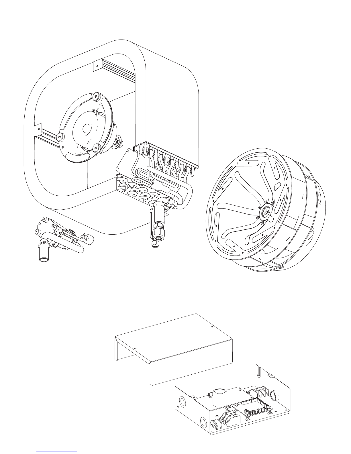
REPLACEMENT PARTS
Models : AUU9RML
AUU12RML
AUU18RML
CONTROL UNIT
41
Page 86

CASSETTE TYPE
DECORATION PANEL
UTG-UFUB-W
REPLACEMENT PARTS
38
Page 87

REPLACEMENT PARTS
CASSETTE TYPE
DECORATION PANEL
UTG-UFUB-W
Flap total assy
Motor holder assy
(connector : white)
(connector : red)
39
Page 88

Model : AOU24RML
AOU24RML1
REPLACEMENT PARTS
03-08
Page 89

Model : AOU24RML
AOU24RML1
REPLACEMENT PARTS
03-09
Page 90

Model : AOU24RML
AOU24RML1
REPLACEMENT PARTS
03-10
Page 91

Model : AOU24RML
AOU24RML1
REPLACEMENT PARTS
Connector : BLACK
GREEN
BLUE
RED
YELLOW
03-11
Connector : RED
WHITE
Page 92

Model : AOU36RML
AOU36RML1
REPLACEMENT PARTS
03-12
Page 93

Model : AOU36RML
AOU36RML1
REPLACEMENT PARTS
03-13
Page 94

Model : AOU36RML
AOU36RML1
REPLACEMENT PARTS
03-14
Page 95
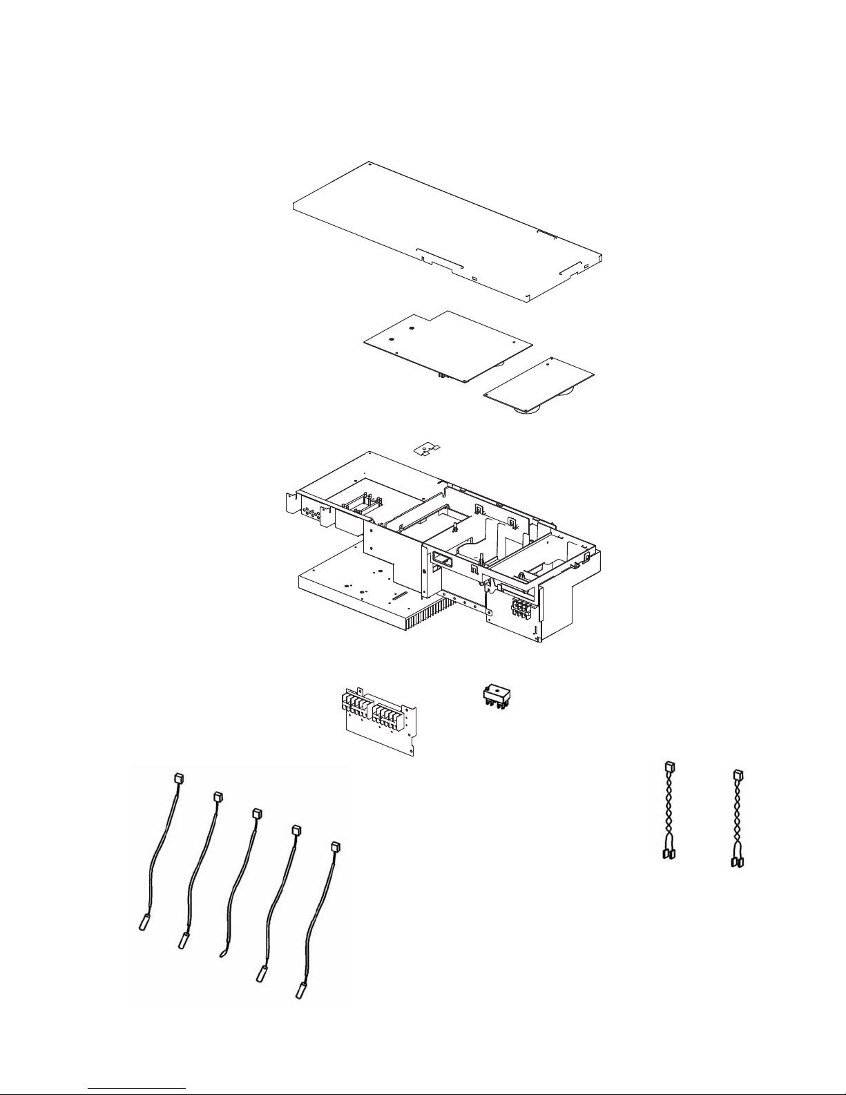
Model : AOU36RML
AOU36RML1
REPLACEMENT PARTS
Connector : BLACK
GREEN
BLUE
RED
YELLOW
03-15
Connector : RED
WHITE
Page 96

REPLACEMENT PARTS
MODEL : AOU24RML
PROCESS
Assemble PWB ASSY
(FILTER PCB)
USED
PARTS
1
INVERTER BOX A
2
FILTER PCB
SCREW,TAPPING
3
REGULATION
As shown in Fig.1, assemble PWB ASSY to INVERTER BOX A.
As shown in Fig.2, pull out the wires of PWB ASSY.
Don't sandwich ARRESTER (SA100) between PWB and INVERTER BOX A.
FILTER PCB
1
INVERTER BOX A
2
Hook
Don't sandwich ARRESTER
between PWB and
INVERTER BOX A.
Fig.1
Pull out the wires of PWB ASSY
this way.
Fig.2
3
SCREW, TAPPING
03-16
Page 97

REPLACEMENT PARTS
MODEL : AOU24RML
PROCESS
Assemble PCB ASSY
USED
PARTS
(MAIN PWB)
REGULATIONS
Certainly set PWB ASSY under the 3 hooks of INVERTER BOX A.
Before it is temporary fix of PCB ASSY, As shown in the Fig.2-5, pull out the wires of PCB ASSY.
After it is temporary fix of PCB ASSY, As shown in the Fig.6-10, pull out the wires of PCB ASSY.
Don't forget to take a cushion D101(DIODE BRIDGE).
Don't bend foot D101(DIODE BRIDGE).
1
INVERTER BOX A
2
MAIN PCB
3
SCREW, TAPPING
W12 YELLOW,W13 BLUE
(MAIN PWB)
WIRE WITH TERMINAL
Don't forget to take a cushion.
Don't bend foot.
Fig.6
1
INVERTER BOX A
Hook
Fig.8-10
Fig.7
Through this hole.
SCREW, TAPPING
3
MAIN PCB
2
Temporarily fix!
Fig.1
03-17
Page 98

REPLACEMENT PARTS
MODEL : AOU24RML
REGULATIONS
As shown in Fig.2, pull out the wires.
2
MAIN PCB
W12 YELLOW,W13 BLUE
(MAIN PCB)
WIRE WITH TERMINAL
Through this hole.
Fig.2
W10 BLACK,W11 WHITE
(MAIN PCB)
WIRE WITH TERMINAL
2
INVERTER BOX A
Through this hole.
03-18
Page 99

REPLACEMENT PARTS
MODEL : AOU24RML
REGULATIONS
As shown in Fig.3, pull out the wires.
W16 RED (MAIN PCB)
WIRE WITH TERMINAL
W200 RED (MAIN PCB)
WIRE WITH TERMINAL
W17 BLACK (MAIN PCB)
WIRE WITH TERMINAL
W201 YELLOW(MAIN PCB)
WIRE WITH TERMINAL
CN1 (MAIN PCB)
WIRE WITH CONNECTOR
Fig.3
W303 BLACK,W304 WHITE,
W305 RED(MAIN PCB)
WIRE WITH CONNECTOR
CN407(MAIN PCB)
WIRE WITH CONNECTOR
HEATSINK THERMISTOR
CN50(MAIN PCB)
WIRE WITH CONNECTOR
CN39(MAIN PCB)
WIRE WITH CONNECTOR
03-19
Page 100

REPLACEMENT PARTS
MODEL : AOU24RML
REGULATIONS
As shown in Fig.4-5, pull out the wires.
W17 BLACK (MAIN PCB)
WIRE WITH TERMINAL
W16 RED (MAIN PCB)
WIRE WITH TERMINAL
W303 BLACK,
W304 WHITE,W305 RED
(MAIN PCB)
WIRE WITH CONNECTOR
CN407(MAIN PCB)
WIRE WITH CONNECTOR
HEATSINK THERMISTOR
Through this hole.
Fig.4
W200 RED (MAIN PCB)
WIRE WITH TERMINAL
W201 YELLOW(MAIN PCB)
WIRE WITH TERMINAL
CN50(MAIN PCB)
WIRE WITH CONNECTOR
CN39(MAIN PCB)
WIRE WITH CONNECTOR
CN1 (MAIN PCB)
WIRE WITH CONNECTOR
Fig.5
03-20
 Loading...