

Page 1
AIR CONDITIONER
Wall Mounted type
DESIGN & TECHNICAL MANUAL
INDOOR
OUTDOOR
ASU9RLS3
ASU12RLS3
ASU15RLS3
AOU9RLS3
AOU12RLS3
AOU15RLS3
Page 2

1. INDOOR UNIT
WALL MOUNTED TYPE :
ASU9RLS3
ASU12RLS3
ASU15RLS3
DTR_AS114E_01
2015.01.23
Page 3

CONTENTS
WALL MOUNTED TYPE
ASU9-15RLS3
WALL MOUNTED TYPE
ASU9-15RLS3
1. INDOOR UNIT
1. FEATURE
.................................................................................................................. 01 - 01
2. WIRELESS REMOTE CONTROLLER
3. SPECIFICATIONS
4. DIMENSIONS
5. WIRING DIAGRAMS
6. CAPACITY TABLE
6-1. COOLING CAPACITY
6-2. HEATING CAPACITY
7. FAN PERFORMANCE
7-1. AIR VELOCITY DISTRIBUTION
7-2. AIR FLOW
.......................................................................................................... 01 - 16
8. OPERATION NOISE
8-1. NOISE LEVEL CURVE
.............................................................................................. 01 - 05
........................................................................................................ 01 - 06
........................................................................................ 01 - 08
............................................................................................ 01 - 09
...................................................................................... 01 - 09
....................................................................................... 01 - 12
.................................................................................... 01 - 14
..................................................................... 01 - 14
......................................................................................... 01 - 18
.................................................................................... 01 - 18
............................................... 01 - 03
8-2. SOUND LEVEL CHECK POINT
9. SAFETY DEVICES
............................................................................................ 01 - 21
..................................................................... 01 - 20
10. EXTERNAL INPUT & OUTPUT
10-1. EXTERNAL INPUT
10-2. EXTERNAL OUTPUT
11. FUNCTION SETTING
11-1. INDOOR UNIT (Setting by remote controller)
12. OPTIONAL PARTS
12-1. CONTROLLER
12-2. OTHERS
............................................................................................................. 01 - 32
........................................................................................... 01 - 22
....................................................................................... 01 - 24
...................................................................................... 01 - 26
........................................................................................... 01 - 32
.................................................................................................. 01 - 32
............................................................... 01 - 22
........................................... 01 - 26
Page 4
FEATURE1.
Powerful
Setting temp.
Normal mode
Time
Temperature
Cross section of
copper pipes
Smooth flow of the refrigerant
(Schematic)
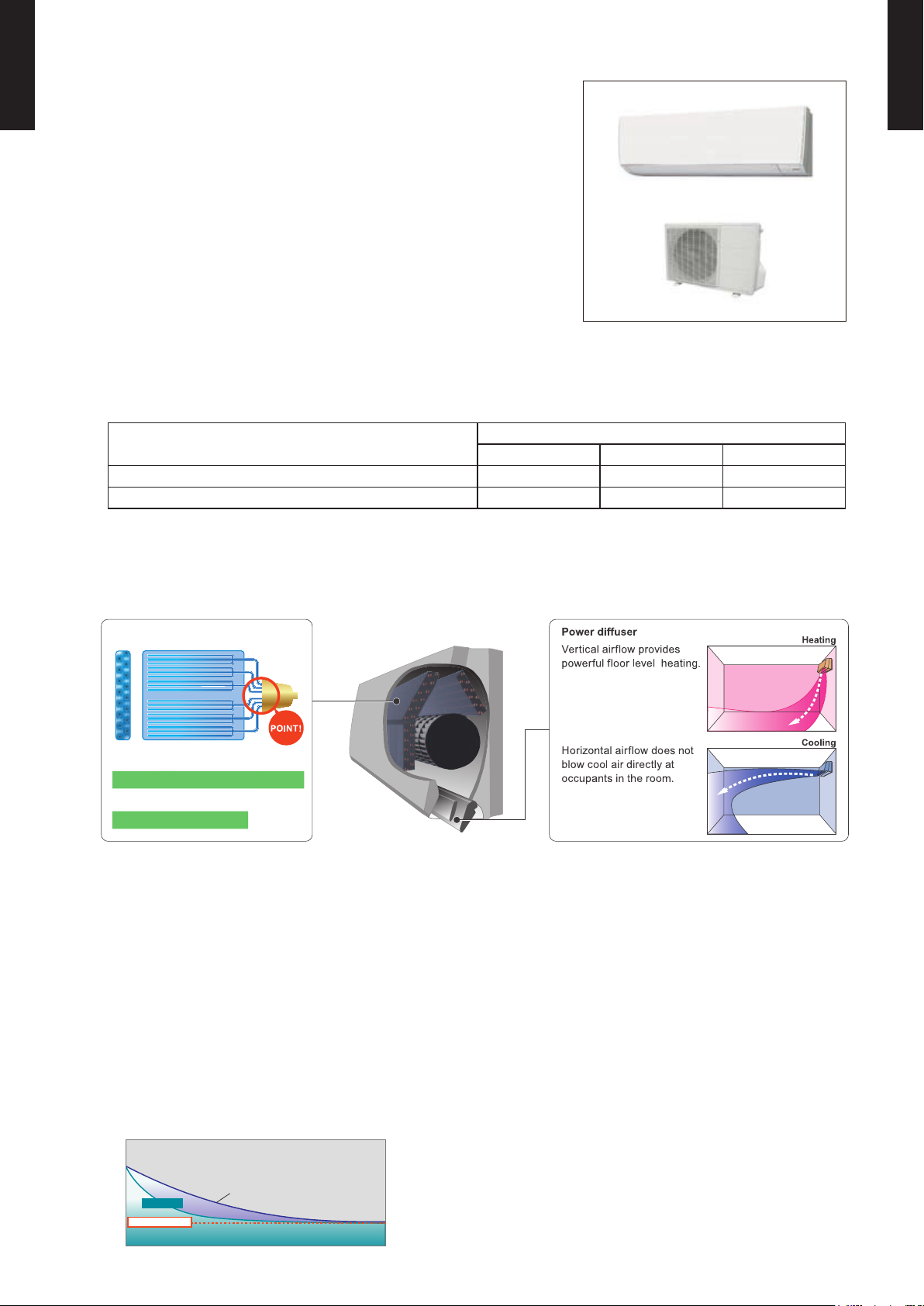
1, Copper pipe diameter 5 mm
High density technology
2, Refrigerant branches 6
Multiple path technology
1,
Copper pipe diameter
3/16in.(5mm)
MODEL
WALL MOUNTED TYPE
ASU9-15RLS3
ASU9RLS3 / AOU9RLS3
WALL MOUNTED TYPE
ASU9-15RLS3
ASU12RLS3 / AOU12RLS3
ASU15RLS3 / AOU15RLS3
FEATURES
Energy Efciency
z
MODEL
ASU9RLS3 ASU12RLS3 ASU15RLS3
Seasonal Energy Efciency Ratio (SEER) 33.0 29.3 25.3
Heating Seasonal Performance Factor (HSPF) 14.2 14.0 13.4
MEASUREMENT CONDITIONS
ANSI/ASHRAE STANDARD 37-1988
High efcient design
z
Powerful heating
z
More comfortable airow
z
Heating capacity was improved at low outdoor temperature. Rated heating capacity is maintained
even at 5°F (-15°C) outdoor temperature. This new model can operate even at -5°F (-21°C) low
outdoor temperature.
Powerful operation
z
*Only available with Wireless RC.
20 minutes continuous operation by maximum airow and maximum compressor speed is
possible. Rapid cooling and heating makes the room comfortable quickly.
Example : Cooling operation
- (01 - 01) -
Page 5
WALL MOUNTED TYPE
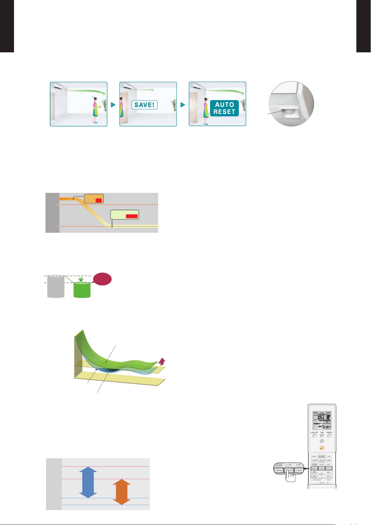
Energy saving operation by detecting someone’s movement
Human
sensor
Rated
noise level
Down
Low noise
mode
Temp.
Economy operation
Shift
setting
temp
Control maxmum current
Nomal operation
Time
Set temperature
-5°F (-21°C)
Cooling
75°F (24°C)
Heating
115°F (46°C)
14°F (-10°C)
122 (50)
104 (40)
86 (30)
68 (20)
50 (10)
32 (0)
14 (-10)
-4 (-20)
“MIN. HEAT”
Button ON
Indoor unit
operation START
68
°F
(20°C)
50
°F
(10°C)
REF3E
ASU9-15RLS3
Energy saving Program
z
*Only available with Wireless RC.
WALL MOUNTED TYPE
ASU9-15RLS3
Human sensor catches movements of people in a room, and operates with lower capacity when the room
is empty. When people come back to the room, it automatically returns to previous operating mode.
MIN. HEAT Operation
z
*Only available with Wireless RC.
The room temperature can be set to go no lower than 50°F (10°C),
thus ensuring that the room does not get too cold when not occupied
Caution)
When the room temperature is higher than 50°F (10°C), “ •
temperature at 50°F (10°C) when the temperature drops below 50°F (10°C).
MIN. HEAT
When “ •
Outdoor unit low noise
z
” operation stops, the room set temperature quickly returns to the preset temperature.
*Only available with Wireless RC.
When air-conditioner operates in large capacity, operation noise of outdoor unit will be suppressed. In case
of room temperature being close to setting temperature, operation noise might not decrease.
Economy operation
z
Example : Cooling operation
MIN. HEAT
” operation does not start. Operation star ts and maintains the room
Economy operation is energy saving, as the set •
temperature of indoor unit is shifted by 2°F (1°C)
and the maximum electric value of the outdoor
unit is suppressed.
5 Mode timer (ON/OFF/Weekly/Program/Sleep)
z
Weekly timer can be easily set by wireless remote controller.
ON, OFF can be set up to 4 times in 1 day and up to 28 times in 1 week.
For other modes, program timer and sleep timer can be also selected by one push.
Low outdoor air temperature correspondence
z
*Only available with Wireless RC.
- (01 - 02) -
Page 6
WIRELESS REMOTE CONTROLLER2.
60min.
2°F (1°C)
4°F (2°C)
Timer setting
30min.
60min.
90min.
4°F
(2°C)
6°F
(3°C)
8°F
(4°C)
Timer setting
2°F
(1°C)
A B C D
A B
C
D
Mixed-up
I.U. I.U. I.U. I.U.
I.U. I.U. I.U. I.U.
After code change
FEATURES
5 Mode timer setup
WALL MOUNTED TYPE
ASU9-15RLS3
Built-in timers
z
Select from 5 Mode timer programs (ON / OFF / Weekly / Program / Sleep).
Weekly timer
z
Weekly timer can be easily set by wireless remote controller.
ON, OFF can be set up to 4 times in 1 day and up to 28 times in 1 week.
¾
(ON / OFF / Weekly / Program / Sleep) are possible.
Easy operation.
¾
Easy to change custom code (max. 4 custom codes) by button
¾
operation.
WALL MOUNTED TYPE
ASU9-15RLS3
Program timer
z
The program timer operates the on and off timer once within a 24 hour period.
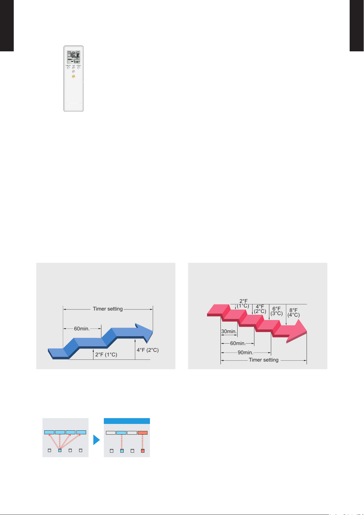
Sleep timer
z
The sleep timer function automatically corrects the temperature thermostat setting according to
the timer setting to prevent excessive cooling and heating while sleeping.
Cooling operation/dry operation
When the sleep timer is set, the set temperature
automatically rises 2°F (1°C) every hour. The set
temperature can rise up to a maximum of 4°F (2°C).
Heating operation
When the sleep timer is set, the set temperature
automatically drops 2°F (1°C) every 30 minutes. The
set temperature can drop to a maximum of 8°F (4°C).
Simple function setting
z
Setting of the air conditioner selection function is performed by remote controller.
Switching remote controller custom code
z
Code selector switch eliminates unit
•
being wrongly switched.
(Up to 4 codes can be set.)
To change the temperature unit
z
Easy to change the temperature unit (°F ↔ °C) by button operation.
*I.U.=Indoor unit
- (01 - 03) -
Page 7

FUNCTIONS
REF3E
WALL MOUNTED TYPE
ASU9-15RLS3
Signal
SENSOR button
WALL MOUNTED TYPE
ASU9-15RLS3
Transmitter
MIN. HEAT
button
TEMP.
button
POWERFUL
button
START/STOP
button
MODE button
ECONOMY button
OUTDOOR UNIT
LOW NOISE button
TIMER SETTING button
SEND button
SELECT button
NEXT button
BACK button
FAN button
SWING button
SET button
WEEKLY button
ON/OFF button
SLEEP button
RESET button
CLOCK ADJUST button
Display panel
Mode indicator
Temperature indicator
Energy Saving
Mode indicator
Turns ON when the
¾
SENSOR button is operated.
Low Noise Mode
indicator
Send indicator
To facilitate explanation, the accompanying illustration has been drawn to show all possible indicators; in actual operation,
however, the display will only show those indicators appropriate to the current operation.
SPECIFICATION
Transmit indicator
Fan Speed indicator
Swing indicator
Clock & Timer
indicator
DIMENSIONS [H × W × D]: in. (mm) 8-1/16 (205) × 2-3/8 (61) × 11/16 (17)
WEIGHT oz. (g) 4.3 (122)
ACCESSORY Holder
- (01 - 04) -
Page 8
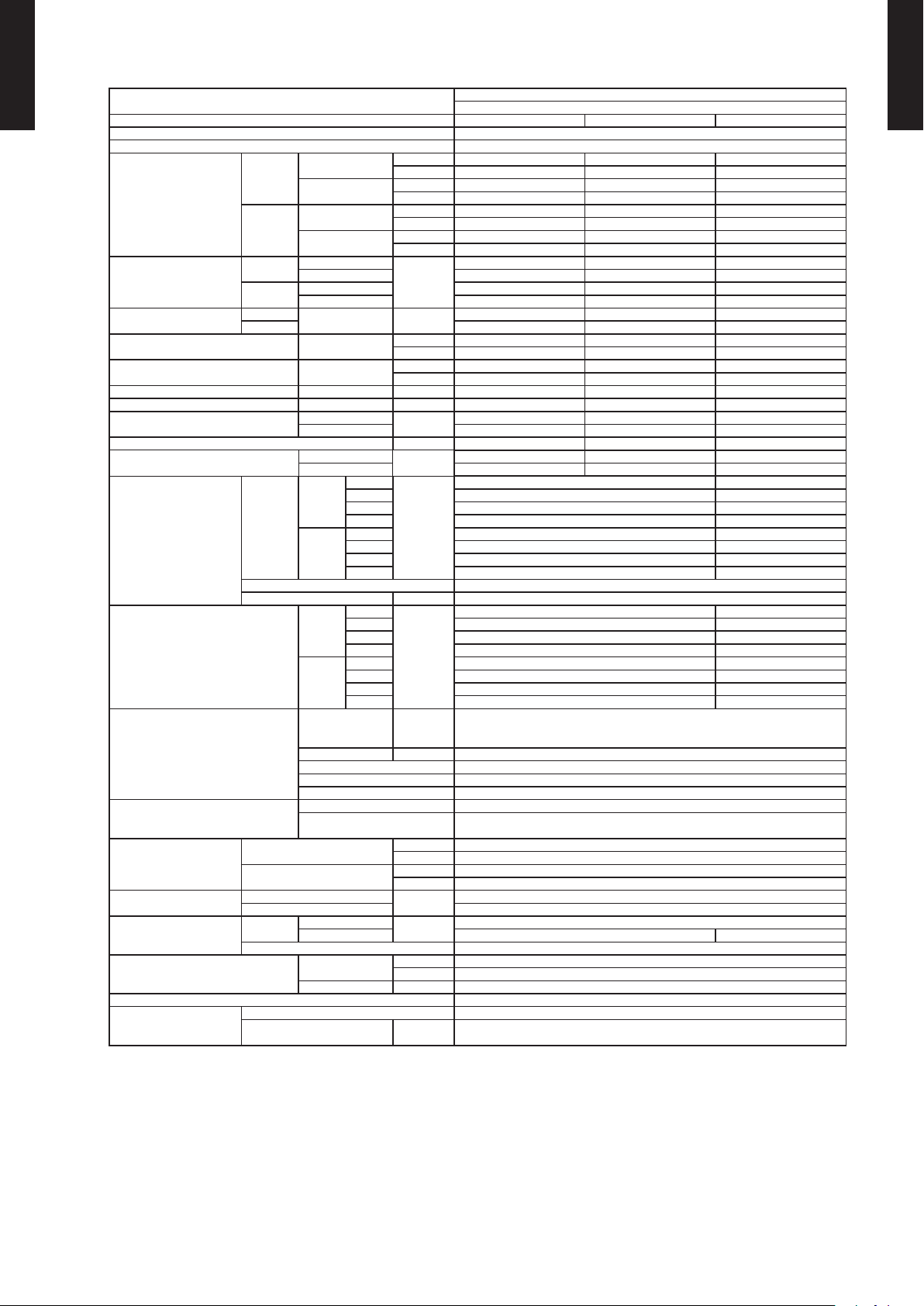
SPECIFICATIONS3.
Typ e
WALL MOUNTED TYPE
ASU9-15RLS3
Model na me ASU9RLS3 ASU12 RLS 3 ASU15R LS3
Power sour ce 208 / 230 V ~ 60Hz
Availabl e voltage r ange 188 - 253V
Cooling
Capacity
Heating
Input pow er
Current
EER Cooling
COP Heating
SEER Cooling Btu/hW 33.0 29.3 25.3
HSPF Heating Btu/hW 14.2 14 .0 13. 4
POWER FACTOR
Moistu re removal pints/ h (l/h) 2 .6 (1.2) 2.7 (1.3) 4.0 (1.9)
Maximum operating current *1
Fan
Sound pr essure lev el *2
Heat excha nger ty pe
Enclosure
Dimensions
(H × W × D)
Weight
Connec tion pip e
Operat ion rang e
Remote co ntroll er type Wireless
Drain ho se
Cooling
Heating
Cooling
Heating 3.3 4.7 5.2
Air ow rate
Type × Q'ty Cross o w fan × 1
Motor ou tput W 61
Net
Gross
Net
Gross 37 (17.0)
Size
Method Flare
Material PP+LLDPF
Size in.( mm)
Rated
Min - Max
Rated
Min - Max
Rated
Max 0.85 0.99 1.56
Rated 0.66 1.01 1.15
Max 1.93 1. 94 2.1 9
Rated A
Cooling
Heating 87 93 96
Cooling
Heating 10.9 10.9 13 .9
Cooling
Heating
Cooling
Heating
Dimensions
(H × W × D)
Fin pitch FPI Main : 21 Sub : 18
Rows × Stag es Main : 3 × 24 S ub : 1 × 10
Pipe typ e Copper
Fin type Aluminum
Material Polystyrene
Color
Liquid
Gas Ø3/8 (Ø9. 52) Ø1/2 (Ø12.7)
Cooling
Heating ° F (°C) 60 to 88 (16 to 30)
High
Med 400 (680) 459( 780)
Low 341( 580) 371(6 30)
Quiet 224(3 80) 259(4 40)
High 489(830) 547( 930)
Med 400 (680) 459( 780)
Low 341( 580) 371(6 30)
Quiet 224(3 80) 294(500)
High
Med 37 40
Low 32 34
Quiet 23 26
High 41 45
Med 35 39
Low 31 33
Quiet 23 27
kW 2.64 3.52 4.25
Btu/h 9,000 12,000 14,5 00
kW 0.90 - 3. 60 0.90 - 4.0 0 0.90 - 5. 40
Btu/h 3,100 - 12,000 3 ,100 - 13,600 3,100 - 18,4 00
kW 3.52 4.69 5.28
Btu/h 12,000 16,000 18,000
kW 0.90 - 6. 45 0.90 - 6. 48 0.9 0 - 7.00
Btu/h 3,100 - 22,000 3,100 - 22,100 31,00 - 23, 900
kW
kW/kW 5. 28 4.46 4.09
Btu/hW 18 .0 15.2 13 .9
kW/kW 5.3 3 4.64 4.59
Btu/hW 18 .2 15.8 15.7
%
A
CFM
(m3/h)
dB (A)
in. (mm)
inch 11 - 5/8 × 37 × 10 - 5/8
mm 295 × 9 40 × 270
inch 14 - 3/8 × 40 - 15/16 × 14
mm 3 65 × 1040 × 3 55
lbs. (kg)
in. (mm)
°F (°C) 64 to 90 (18 to 32)
%RH 80 or les s
0.50 0.79 1.0 4
2.5 3.8 4.8
87 90 94
9.4 9.4 9.9
489(830) 547(9 30)
Main : 15-1/8 × 28 -3/8 × 1-3/16 (384 × 7 20 × 30)
Sub : 3- 5/16 × 28- 3/8 × 1/2 (8 4 × 720 × 13.3)
Approx imate col or of MUN SELL 5PB 9 .25/0. 5
WALL MOU NTED
INVERT ER HEAT PUM P
42 45
4-15/16 × 28- 3/8 × 1/2 (126 × 720 × 13.3)
White
31 (14.0)
Ø1/4 (Ø6.35)
Ø9/16 (Ø13.8) (I. D.)
Ø5/8 to Ø11/16 (Ø15.8 to Ø16.7) (O.D.)
WALL MOUNTED TYPE
ASU9-15RLS3
NOTE :
• Specications are based on the following conditions.
Cooling : Indoor temperature of 80°F (26.67°C) DB / 67°F (19.44°C) WB, and outdoor temperature of 95°F (35°C) DB / 75°F (23.9°C) WB.
Heating : Indoor temperature of 70°F (21.11°C) DB / 59°F (15°C) WB, and outdoor temperature of 47°F (8.33°C) DB / 43°F (6.11°C) WB.
Pipe length : 24ft.7in (7.5m), Height difference:0 m. (Outdoor unit-Indoor unit)
• The protective function might work when using it outside the operation range.
*1: The maxim um curr ent is the maximum value when operate d within t he oper ation ra nge.
*2: Thes e are the me asured va lues in th e manufacturer ’s anech oic cham ber.
Because of the sur rounding sound environment, the sound leve ls measu red in act ual inst allation conditions might be hig her than t he spec ied val ues here.
- (01 - 05) -
Page 9
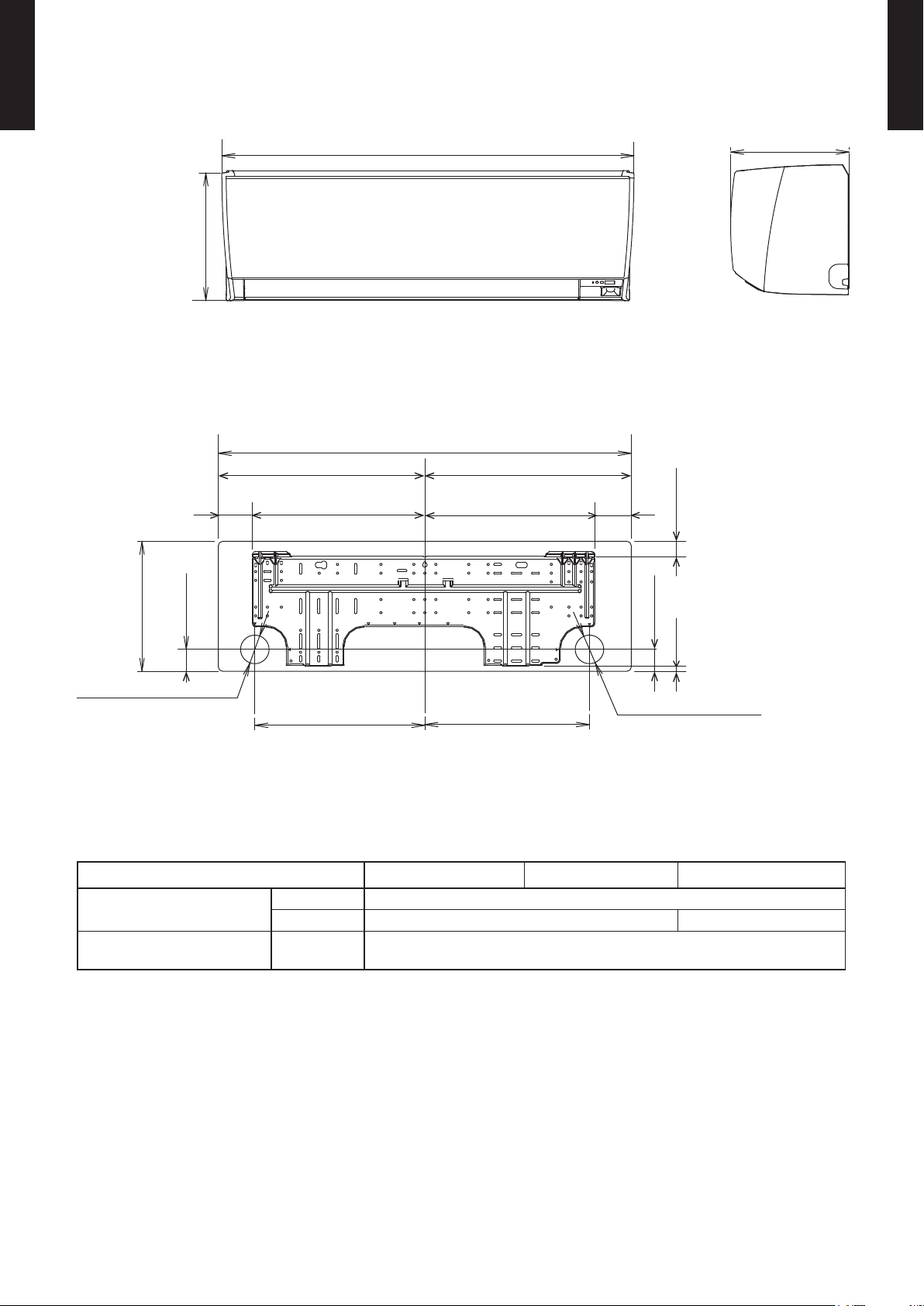
DIMENSIONS4.
14-3/4(375)
for pipe inlet Ø2-9/16(65)
for pipe inlet Ø2-9/16(65)
15-1/4(387)
18-1/2(470) 18-1/2(470)
10-5/8(270)
1-11/16(43)
(11-5/8(295))
11-5/8(295)
37(940)
37(940)
15-1/4(387)
3-1/4
(83)
3-1/16
(77)
15-7/16(393)
1-9/16(40)3/8(9)
1-11/16(43)
MODEL : ASU9RLS3, ASU12RLS3, ASU15RLS3
WALL MOUNTED TYPE
ASU9-15RLS3
Unit : in. (mm)
WALL MOUNTED TYPE
ASU9-15RLS3
Refrigerant pipe are
connection
Liquid Ø 1/4 in. (Ø 6.35 mm)
Gas Ø 3/8 in. (Ø 9.52 mm) Ø 1/2 in. (Ø 12.7 mm)
Drain hose connection Drain hose
ASU9RLS3 ASU12RLS3 ASU15RLS3
(Ø 9/16 in. (I.D.), Ø 5/8 to Ø 11/16 in. (O.D.)
[Ø 13.8 mm (I.D.), Ø 15.8 to 16.7 mm (O.D.)]
- (01 - 06) -
Page 10
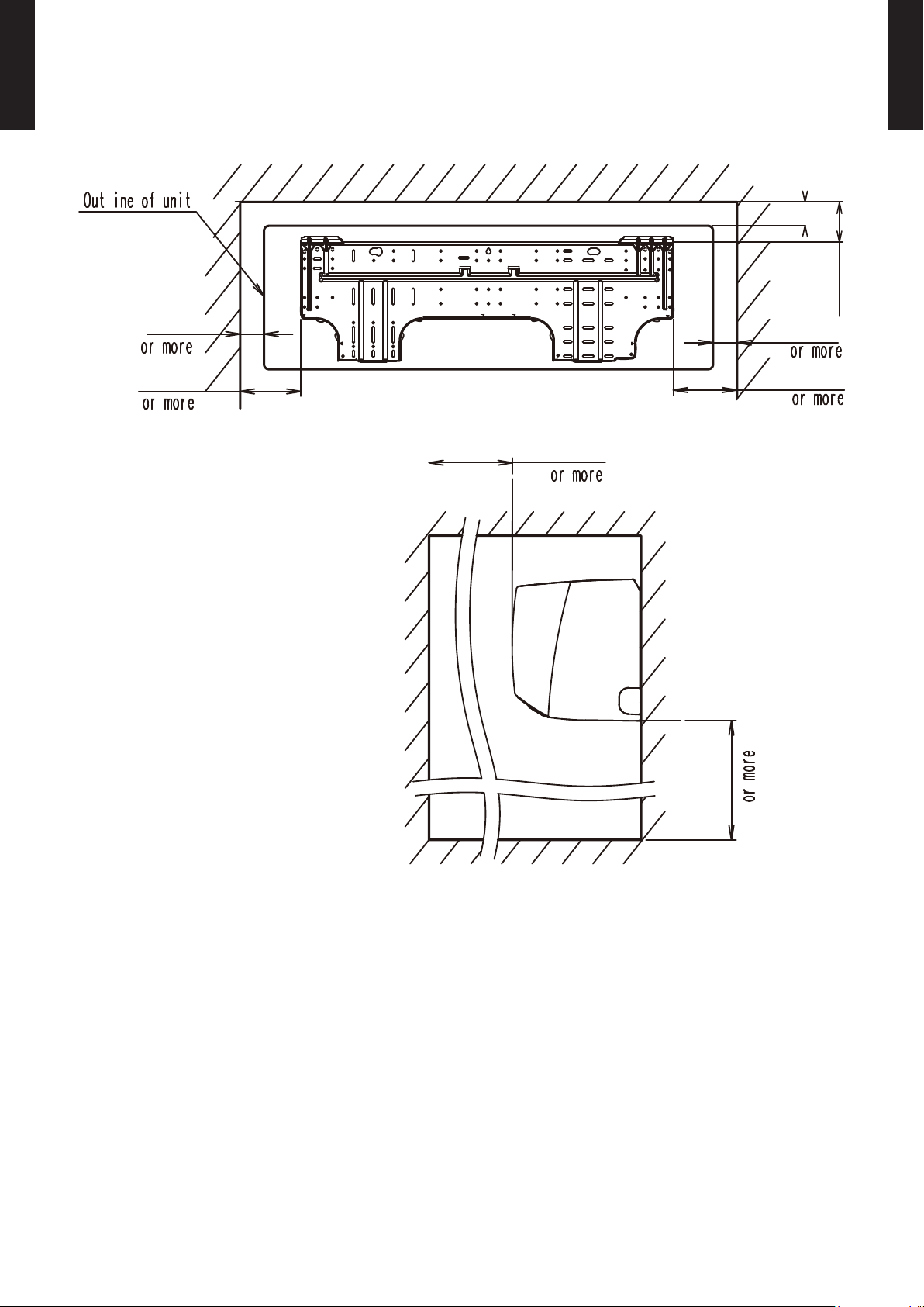
WALL MOUNTED TYPE
2(50)
5(127)
2(50)
6(133)
60(1,500)
2(50)
or more
or more
4(84)
71(1,800)
ASU9-15RLS3
INSTALLATION PLACE
Unit : in. (mm)
WALL MOUNTED TYPE
ASU9-15RLS3
- (01 - 07) -
Page 11
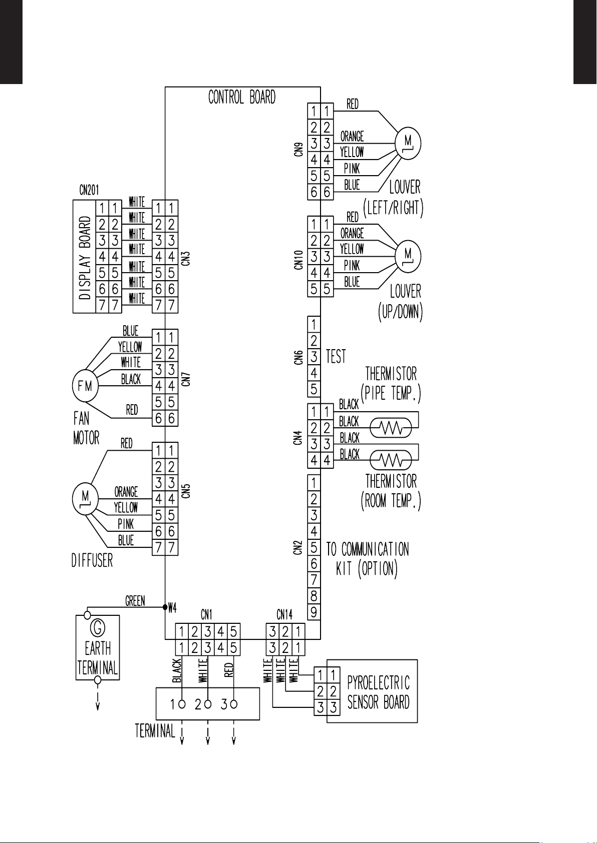
WIRING DIAGRAMS5.
MODEL : ASU9RLS3, ASU12RLS3, ASU15RLS3
WALL MOUNTED TYPE
ASU9-15RLS3
WALL MOUNTED TYPE
ASU9-15RLS3
- (01 - 08) -
Page 12

CAPACITY TABLE6.
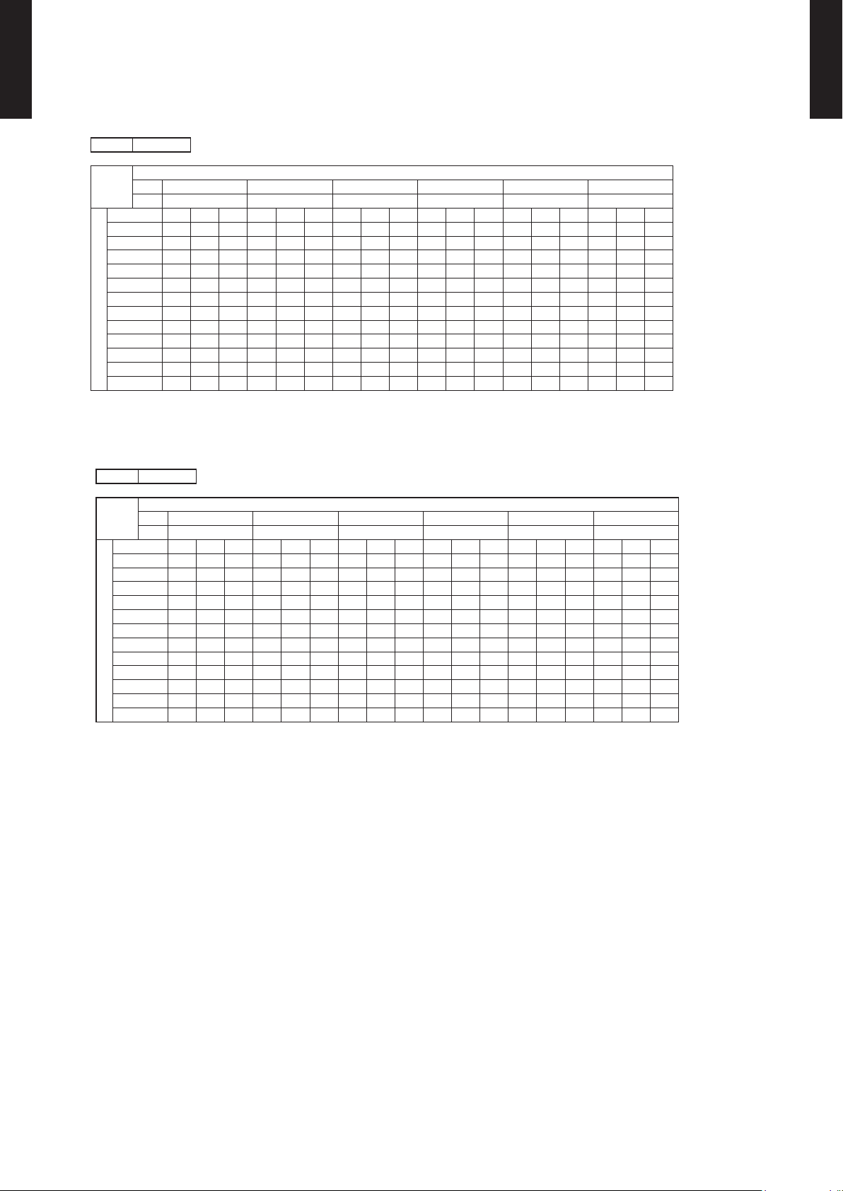
COOLING CAPACITY6-1.
WALL MOUNTED TYPE
ASU9-15RLS3
MODEL : ASU9RLS3
AFR 489
WALL MOUNTED TYPE
ASU9-15RLS3
°FDB 64 70 75 80 85 90
°FWB 54 60 63 67 71 73
°FDB TC SHC IP TC SHC IP TC SHC IP TC SHC IP TC SHC IP TC SHC IP
15 8.33 8.06 0.19 9.29 8.11 0.19 10.25 8.87 0.20 10.57 9.53 0.20 11.17 9.50 0.20 11.81 10.07 0.21
23 8.16 7.88 0.22 9.09 7.91 0.22 10.03 8.65 0.23 10.35 9.31 0.22 10.94 9.28 0.22 11.56 9.91 0.23
32 7.99 7.69 0.22 8.90 7.75 0.23 9.81 8.45 0.24 10.13 9.16 0.23 10.70 9.09 0.23 11.32 9.68 0.24
41 7.81 7.58 0.24 8.71 7.61 0.24 9.60 8.28 0.25 9.90 8.97 0.24 10.47 8.90 0.24 11.07 9.50 0.25
50 7.64 7.36 0.22 8.51 7.41 0.22 9.38 8.07 0.24 9.68 8.76 0.23 10.24 8.70 0.23 10.83 9.26 0.24
59 7.47 7.24 0.27 8.32 7.27 0.27 9.16 7.91 0.28 9.46 8.57 0.28 10.01 8.51 0.28 10.58 9.08 0.28
67 8.42 8.15 0.34 9.38 8.18 0.35 10.33 8.94 0.36 10.67 9.63 0.36 11.28 9.59 0.36 11.93 10.18 0.37
77 8.01 7.74 0.39 8.93 7.77 0.39 9.85 8.49 0.40 10.16 9.15 0.40 10.74 9.11 0.41 11.35 9.73 0.41
Outdoor temperature
87 7.57 7.29 0.44 8.45 7.36 0.44 9.31 8.01 0.45 9.58 8.67 0.45 10.16 8.63 0.46 10.74 9.18 0.46
95 7.09 6.88 0.48 7.91 6.91 0.49 8.73 7.53 0.50 9.00 8.15 0.50 9.55 8.12 0.51 10.06 8.63 0.51
104 6.00 5.67 0.45 6.68 6.16 0.46 7.36 6.71 0.46 7.60 7.26 0.46 8.05 7.22 0.47 8.52 7.70 0.47
115 5.52 5.33 0.45 6.17 5.71 0.46 6.78 6.22 0.46 6.99 6.74 0.46 7.43 6.71 0.47 7.84 7.15 0.47
AFR : Air Fl ow Rate (CFM)
TC : Total Capaci ty (kBtu /h)
SHC : Sens ible Hea t Capaci ty (kBtu /h)
IP : Input Po wer (kW)
AFR 13.8
°CDB 17.8 21.1 23.9 26.7 29.4 32.2
°CWB 12.2 15.6 17.2 19.4 21.7 22.8
°CDB TC SHC IP TC SHC IP TC SHC IP TC SHC IP TC SHC IP TC SHC IP
-10.0 2.44 2.36 0.19 2.72 2.38 0.19 3.00 2.60 0.20 3.10 2.79 0.20 3.27 2.78 0.20 3.46 2.95 0.21
-5.0 2.39 2.31 0.22 2.67 2.32 0.22 2.94 2.53 0.23 3.03 2.73 0.22 3.21 2.72 0.22 3.39 2.90 0.23
0.0 2.34 2.25 0.22 2.61 2.27 0.23 2.88 2.48 0.24 2.97 2.68 0.23 3.14 2.67 0.23 3.32 2.84 0.24
5.0 2.29 2.22 0.24 2.55 2.23 0.24 2.81 2.43 0.25 2.90 2.63 0.24 3.07 2.61 0.24 3.25 2.79 0.25
10.0 2.24 2.16 0.22 2.49 2.17 0.22 2.75 2.37 0.24 2.84 2.57 0.23 3.00 2.55 0.23 3.17 2.71 0.24
15.0 2.19 2.12 0.27 2.44 2.13 0.27 2.69 2.32 0.28 2.77 2.51 0.28 2.93 2.49 0.28 3.10 2.66 0.28
19.4 2.47 2.39 0.34 2.75 2.40 0.35 3.03 2.62 0.36 3.13 2.82 0.36 3.31 2.81 0.36 3.50 2.98 0.37
25.0 2.35 2.27 0.39 2.62 2.28 0.39 2.89 2.49 0.40 2.98 2.68 0.40 3.15 2.67 0.41 3.33 2.85 0.41
Outdoor temperature
30.6 2.22 2.14 0.44 2.48 2.16 0.44 2.73 2.35 0.45 2.81 2.54 0.45 2.98 2.53 0.46 3.15 2.69 0.46
35.0 2.08 2.02 0.48 2.32 2.03 0.49 2.56 2.21 0.50 2.64 2.39 0.50 2.80 2.38 0.51 2.95 2.53 0.51
40.0 1.76 1.66 0.45 1.96 1.80 0.46 2.16 1.97 0.46 2.23 2.13 0.46 2.36 2.12 0.47 2.50 2.26 0.47
46.0 1.62 1.56 0.45 1.81 1.67 0.46 1.99 1.82 0.46 2.05 1.98 0.46 2.18 1.97 0.47 2.30 2.10 0.47
AFR : Air Fl ow Rate (m3/min)
TC : Total Capaci ty (kW)
SHC : Sens ible Hea t Capaci ty (kW)
IP : Input Po wer (kW)
Indoor temperature
Indoor temperature
- (01 - 09) -
Page 13

WALL MOUNTED TYPE
ASU9-15RLS3
MODEL : ASU12RLS3
AFR 489
WALL MOUNTED TYPE
ASU9-15RLS3
°FDB 64 70 75 80 85 90
°FWB 54 60 63 67 71 73
°FDB TC SHC IP TC SHC IP TC SHC IP TC SHC IP TC SHC IP TC SHC IP
15 10.34 9.52 0.28 11.53 9.58 0.28 12.72 10.47 0.29 13.11 11.30 0.29 13.87 11.21 0.29 14.67 11.96 0.30
23 10.26 9.44 0.33 11.44 9.47 0.33 12.62 10.34 0.35 13.01 11.19 0.34 13.77 11.12 0.34 14.56 11.85 0.35
32 10.18 9.35 0.36 11.36 9.39 0.36 12.52 10.27 0.38 12.91 11.09 0.37 13.67 11.03 0.38 14.45 11.78 0.39
41 10.10 9.30 0.39 11.27 9.37 0.39 12.42 10.21 0.41 12.81 11.02 0.40 13.57 10.98 0.40 14.34 11.68 0.41
50 10.03 9.21 0.40 11.18 9.25 0.40 12.32 10.10 0.42 12.71 10.92 0.41 13.47 10.86 0.41 14.23 11.60 0.42
59 9.95 9.16 0.41 11.10 9.23 0.41 12.22 10.05 0.44 12.61 10.85 0.42 13.37 10.81 0.43 14.12 11.50 0.44
67 11.22 10.32 0.54 12.51 10.40 0.55 13.77 11.34 0.55 14.22 12.25 0.56 15.07 12.18 0.56 15.92 12.98 0.57
77 10.67 9.82 0.62 11.90 9.85 0.63 13.13 10.76 0.64 13.53 11.63 0.64 14.32 11.56 0.64 15.14 12.32 0.65
Outdoor temperature
87 10.09 9.27 0.69 11.25 9.31 0.70 12.41 10.18 0.71 12.78 10.98 0.71 13.57 10.94 0.72 14.32 11.67 0.73
95 9.48 8.72 0.76 10.53 8.76 0.77 11.63 9.56 0.79 12.00 10.32 0.79 12.72 10.29 0.80 13.43 10.94 0.81
104 8.01 7.78 0.71 8.93 7.82 0.72 9.82 8.51 0.73 10.13 9.20 0.74 10.74 9.16 0.74 11.35 9.78 0.75
115 7.36 7.20 0.71 8.22 7.23 0.72 9.07 7.89 0.74 9.34 8.54 0.74 9.89 8.51 0.74 10.47 9.05 0.75
AFR : Air Fl ow Rate (CFM)
TC : Total Capaci ty (kBtu /h)
SHC : Sens ible Hea t Capaci ty (kBtu /h)
IP : Input Po wer (kW)
AFR 13.8
°CDB 17.8 21.1 23.9 26.7 29.4 32.2
°CWB 12.2 15.6 17.2 19.4 21.7 22.8
°CDB TC SHC IP TC SHC IP TC SHC IP TC SHC IP TC SHC IP TC SHC IP
-10.0 3.03 2.79 0.28 3.38 2.81 0.28 3.73 3.07 0.29 3.84 3.31 0.29 4.07 3.29 0.29 4.30 3.50 0.30
-5.0 3.01 2.77 0.33 3.35 2.78 0.33 3.70 3.03 0.35 3.81 3.28 0.34 4.04 3.26 0.34 4.27 3.47 0.35
0.0 2.98 2.74 0.36 3.33 2.75 0.36 3.67 3.01 0.38 3.78 3.25 0.37 4.01 3.23 0.38 4.23 3.45 0.39
5.0 2.96 2.73 0.39 3.30 2.75 0.39 3.64 2.99 0.41 3.75 3.23 0.40 3.98 3.22 0.40 4.20 3.42 0.41
10.0 2.94 2.70 0.40 3.28 2.71 0.40 3.61 2.96 0.42 3.73 3.20 0.41 3.95 3.18 0.41 4.17 3.40 0.42
15.0 2.92 2.68 0.41 3.25 2.71 0.41 3.58 2.94 0.44 3.70 3.18 0.42 3.92 3.17 0.43 4.14 3.37 0.44
19.4 3.29 3.03 0.54 3.67 3.05 0.55 4.04 3.32 0.55 4.17 3.59 0.56 4.42 3.57 0.56 4.67 3.80 0.57
25.0 3.13 2.88 0.62 3.49 2.89 0.63 3.85 3.15 0.64 3.97 3.41 0.64 4.20 3.39 0.64 4.44 3.61 0.65
Outdoor temperature
30.6 2.96 2.72 0.69 3.30 2.73 0.70 3.64 2.98 0.71 3.75 3.22 0.71 3.98 3.21 0.72 4.20 3.42 0.73
35.0 2.78 2.56 0.76 3.09 2.57 0.77 3.41 2.80 0.79 3.52 3.03 0.79 3.73 3.02 0.80 3.94 3.21 0.81
40.0 2.35 2.28 0.71 2.62 2.29 0.72 2.88 2.49 0.73 2.97 2.70 0.74 3.15 2.68 0.74 3.33 2.87 0.75
46.0 2.16 2.11 0.71 2.41 2.12 0.72 2.66 2.31 0.74 2.74 2.50 0.74 2.90 2.49 0.74 3.07 2.65 0.75
AFR : Air Fl ow Rate (m3/min)
TC : Total Capaci ty (kW)
SHC : Sens ible Hea t Capaci ty (kW)
IP : Input Po wer (kW)
Indoor temperature
Indoor temperature
- (01 - 10) -
Page 14
WALL MOUNTED TYPE
ASU9-15RLS3
MODEL : ASU15RLS3
AFR 547
WALL MOUNTED TYPE
ASU9-15RLS3
°FDB 64 70 75 80 85 90
°FWB 54 60 63 67 71 73
°FDB TC SHC IP TC SHC IP TC SHC IP TC SHC IP TC SHC IP TC SHC IP
15 12.72 9.80 0.36 14.18 10.92 0.36 15.63 12.04 0.38 16.10 12.40 0.37 17.04 13.13 0.37 18.02 13.88 0.38
23 12.53 9.62 0.39 13.95 10.72 0.39 15.38 11.82 0.41 15.85 12.18 0.40 16.78 12.90 0.40 17.75 13.63 0.42
32 12.33 9.49 0.40 13.73 10.57 0.41 15.14 11.65 0.43 15.60 12.01 0.42 16.52 12.72 0.42 17.47 13.45 0.43
41 12.13 9.34 0.41 13.51 10.41 0.41 14.89 11.47 0.43 15.35 11.82 0.42 16.26 12.52 0.42 17.19 13.24 0.44
50 11.93 9.18 0.42 13.29 10.23 0.42 14.65 11.27 0.45 15.10 11.62 0.43 16.00 12.31 0.44 16.91 13.01 0.45
59 11.73 9.01 0.45 13.07 10.04 0.45 14.41 11.07 0.48 14.85 11.41 0.46 15.74 12.10 0.46 16.64 12.78 0.48
67 13.48 11.10 0.72 15.01 11.17 0.74 16.55 12.15 0.75 17.06 13.14 0.75 18.08 13.07 0.76 19.11 13.95 0.76
77 12.86 10.57 0.82 14.33 10.64 0.83 15.80 11.59 0.84 16.27 12.50 0.84 17.23 12.47 0.85 18.22 13.28 0.86
Outdoor temperature
87 12.18 10.00 0.91 13.58 10.07 0.92 14.98 10.99 0.94 15.42 11.87 0.95 16.34 11.84 0.95 17.30 12.61 0.96
95 11.46 9.40 1.01 12.76 9.48 1.02 14.06 10.32 1.03 14.50 11.17 1.04 15.35 11.10 1.05 16.24 11.84 1.06
104 10.06 8.28 0.99 11.22 8.31 1.01 12.35 9.09 1.02 12.73 9.79 1.02 13.51 9.76 1.03 14.26 10.39 1.05
115 9.18 7.54 0.97 10.20 7.57 0.99 11.26 8.28 1.01 11.60 8.91 1.01 12.32 8.88 1.02 13.00 9.48 1.03
AFR : Air Fl ow Rate (CFM)
TC : Total Capaci ty (kBtu /h)
SHC : Sens ible Hea t Capaci ty (kBtu /h)
IP : Input Po wer (kW)
AFR 15.5
°CDB 17.8 21.1 23.9 26.7 29.4 32.2
°CWB 12.2 15.6 17.2 19.4 21.7 22.8
°CDB TC SHC IP TC SHC IP TC SHC IP TC SHC IP TC SHC IP TC SHC IP
-10.0 3.73 2.87 0.36 4.15 3.20 0.36 4.58 3.53 0.38 4.72 3.63 0.37 5.00 3.85 0.37 5.28 4.07 0.38
-5.0 3.67 2.82 0.39 4.09 3.14 0.39 4.51 3.46 0.41 4.65 3.57 0.40 4.92 3.78 0.40 5.20 4.00 0.42
0.0 3.61 2.78 0.40 4.02 3.10 0.41 4.44 3.42 0.43 4.57 3.52 0.42 4.84 3.73 0.42 5.12 3.94 0.43
5.0 3.56 2.74 0.41 3.96 3.05 0.41 4.37 3.36 0.43 4.50 3.46 0.42 4.77 3.67 0.42 5.04 3.88 0.44
10.0 3.50 2.69 0.42 3.90 3.00 0.42 4.29 3.30 0.45 4.43 3.41 0.43 4.69 3.61 0.44 4.96 3.81 0.45
15.0 3.44 2.64 0.45 3.83 2.94 0.45 4.22 3.24 0.48 4.35 3.34 0.46 4.61 3.54 0.46 4.88 3.75 0.48
19.4 3.95 3.25 0.72 4.40 3.27 0.74 4.85 3.56 0.75 5.00 3.85 0.75 5.30 3.83 0.76 5.60 4.09 0.76
25.0 3.77 3.10 0.82 4.20 3.12 0.83 4.63 3.40 0.84 4.77 3.66 0.84 5.05 3.65 0.85 5.34 3.89 0.86
Outdoor temperature
30.6 3.57 2.93 0.91 3.98 2.95 0.92 4.39 3.22 0.94 4.52 3.48 0.95 4.79 3.47 0.95 5.07 3.70 0.96
35.0 3.36 2.76 1.01 3.74 2.78 1.02 4.12 3.02 1.03 4.25 3.27 1.04 4.50 3.25 1.05 4.76 3.47 1.06
40.0 2.95 2.43 0.99 3.29 2.44 1.01 3.62 2.66 1.02 3.73 2.87 1.02 3.96 2.86 1.03 4.18 3.05 1.05
46.0 2.69 2.21 0.97 2.99 2.22 0.99 3.30 2.43 1.01 3.40 2.61 1.01 3.61 2.60 1.02 3.81 2.78 1.03
AFR : Air Fl ow Rate (m3/min)
TC : Total Capaci ty (kW)
SHC : Sens ible Hea t Capaci ty (kW)
IP : Input Po wer (kW)
Indoor temperature
Indoor temperature
- (01 - 11) -
Page 15
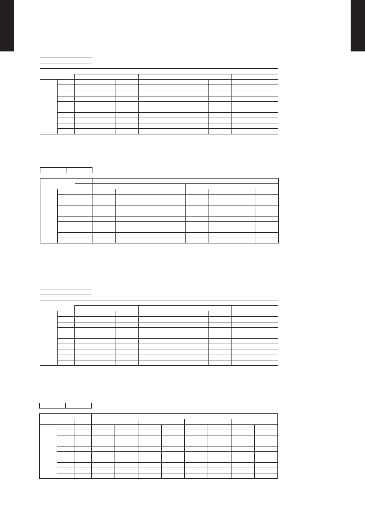
HEATING CAPACITY6-2.
WALL MOUNTED TYPE
ASU9-15RLS3
MODEL : ASU9RLS3
AFR 487
WALL MOUNTED TYPE
ASU9-15RLS3
°FDB °FWB TC IP TC IP TC IP TC IP
-5 -7 14.7 2.01 14.3 2.05 14.0 2.09 13. 3 2.17
5 3 16.1 2.02 15.7 2.06 15.4 2 .10 14.6 2 .19
14 12 16.8 1.98 16.4 2.02 16.0 2.07 15.2 2.1 5
23 19 18.3 1.95 17.9 1.99 17. 5 2. 03 16.6 2.11
32 28 18.8 1.91 18.4 1.9 5 17.9 1.99 17.0 2.07
41 37 21.3 1.8 8 20.8 1.9 2 20.3 1.95 19.3 2 .03
47 43 23 .1 1.85 22. 6 1.89 22. 0 1.93 20. 9 2.01
Outdoo r temper ature
50 47 25. 5 1.84 24. 9 1.88 24. 3 1.91 23.1 1.99
59 50 26.5 1.63 2 5.8 1.67 2 5.2 1.70 23.9 1.77
AFR : Air Fl ow Rate (CFM)
TC : Total Capaci ty (kBtu /h)
IP : Input Po wer (kW)
AFR 13 .8
°CDB °CWB TC IP TC IP TC IP TC IP
-20.6 -21.7 4.31 2.01 4. 20 2.05 4.10 2.09 3.90 2.17
-15.0 -16.1 4.73 2.02 4.61 2.06 4.5 0 2.10 4. 28 2.19
-10.0 -11.1 4.91 1.9 8 4.80 2 .02 4.68 2.07 4.45 2 .15
-5.0 -7.2 5.3 8 1.95 5.2 5 1.99 5.1 2 2.03 4.8 6 2.11
0.0 -2. 2 5.52 1.91 5. 39 1.95 5. 26 1.99 5. 00 2.07
5.0 2. 8 6 .25 1.88 6.10 1.92 5.95 1.9 5 5.65 2. 03
8.3 6.1 6.77 1.85 6.61 1.8 9 6.45 1.9 3 6.13 2 .01
Outdoo r temper ature
10.0 8. 3 7.48 1.84 7.30 1.88 7.1 3 1.91 6.77 1.99
15.0 10.0 7.75 1.6 3 7.57 1.67 7.38 1.70 7.02 1.77
°FDB 60 65 70 75
Indoor t empera ture
Indoor t empera ture
°CDB 15.6 18.3 2 1.1 23.9
AFR : Air Fl ow Rate (m3/min)
TC : Total Capaci ty (kW)
IP : Input Po wer (kW)
MODEL : ASU12RLS3
AFR 487
°FDB 60 65 70 75
°FDB °FWB TC IP TC IP TC IP TC IP
-5 -7 15.8 2.01 15.4 2.05 15.0 2.09 14.3 2.17
5 3 17.4 2.02 17.0 2.0 6 16.6 2.10 15.8 2.19
14 12 18.3 1.9 8 17.8 2 .03 17.4 2.07 16.5 2 .15
23 19 20. 0 1.95 19.5 1.99 19. 0 2.03 18.1 2.11
32 28 20.6 1.9 2 20.1 1.9 6 19.6 2. 00 18.6 2 .08
41 37 22.5 1.8 8 21.9 1.9 2 21.4 1.9 6 20.3 2.04
47 43 23.2 1.86 22.7 1.90 2 2.1 1.94 21.0 2.02
Outdoo r temper ature
50 47 25. 6 1.85 25.0 1.89 24. 4 1.93 23 .2 2.00
59 50 26.6 1.64 2 5.9 1.68 25.3 1.71 24.0 1.78
AFR : Air Fl ow Rate (CFM)
TC : Total Capaci ty (kBtu /h)
IP : Input Po wer (kW)
AFR 13 .8
°CDB 15.6 18.3 2 1.1 23.9
°CDB °CWB TC IP TC IP TC IP TC IP
-20.6 -21.7 4.63 2.01 4.52 2.05 4.41 2.09 4 .19 2.17
-15.0 -16.1 5.11 2 .02 4.99 2 .06 4.8 6 2.10 4.6 2 2.19
-10.0 -11.1 5.36 1.9 8 5.23 2 .03 5 .10 2.07 4.85 2 .15
-5.0 -7.2 5.8 6 1.95 5.72 1.99 5.5 8 2.03 5.3 0 2 .11
0.0 -2. 2 6.03 1.92 5.88 1.96 5.74 2.00 5.45 2.08
5.0 2. 8 6 .58 1.88 6.43 1.92 6.27 1.9 6 5.96 2.04
8.3 6.1 6.80 1.86 6.64 1.9 0 6.48 1.9 4 6 .15 2. 02
Outdoo r temper ature
10.0 8. 3 7.52 1.85 7.34 1.89 7.16 1.93 6. 80 2.00
15.0 10.0 7.79 1.6 4 7.60 1.6 8 7.42 1.71 7.05 1.78
Indoor t empera ture
Indoor t empera ture
AFR : Air Fl ow Rate (m3/min)
TC : Total Capaci ty (kW)
IP : Input Po wer (kW)
- (01 - 12) -
Page 16
WALL MOUNTED TYPE
ASU9-15RLS3
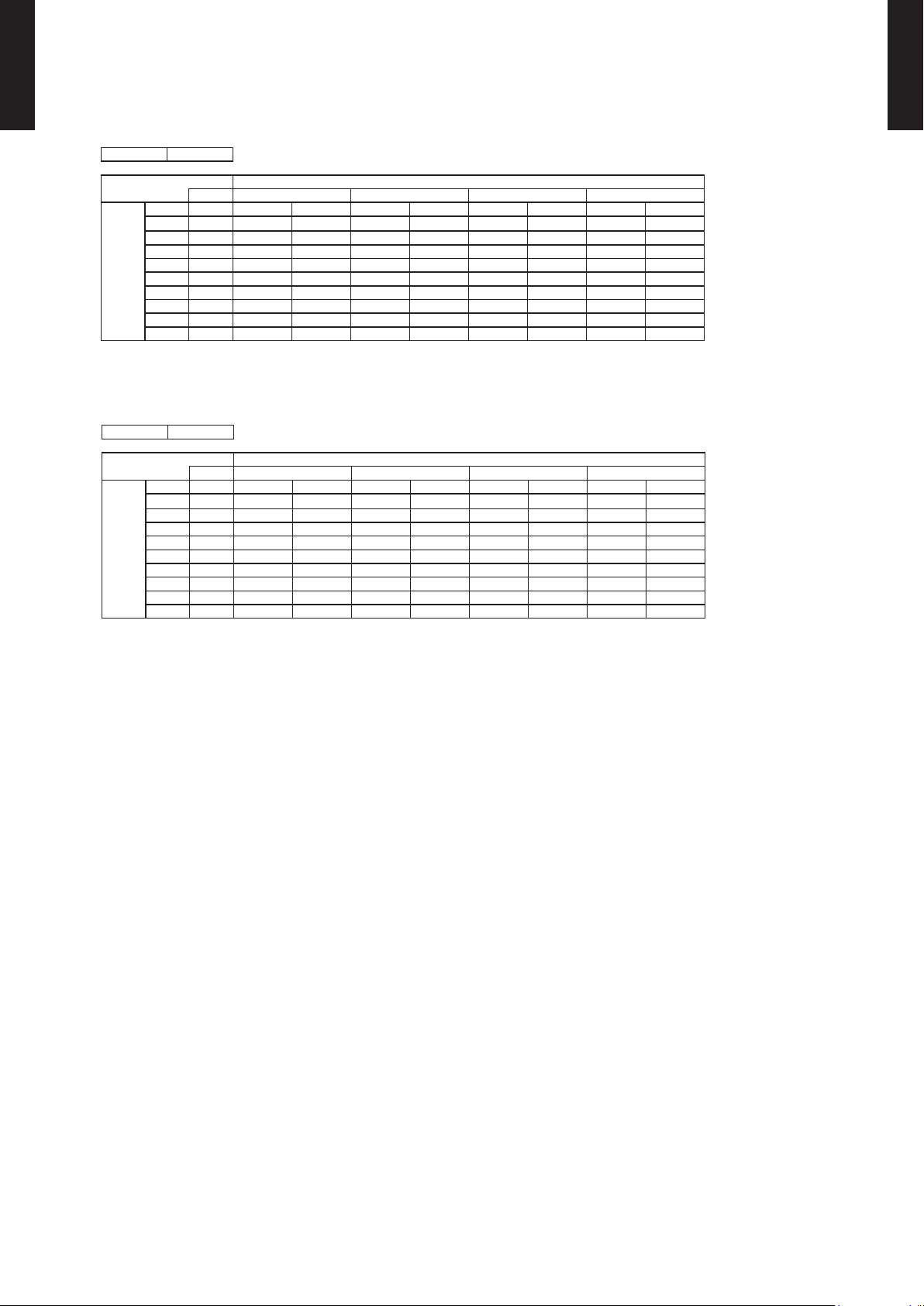
MODEL : ASU15RLS3
AFR 547
WALL MOUNTED TYPE
ASU9-15RLS3
°FDB °FWB TC IP TC IP TC IP TC IP
-5 -7 19.6 2 .63 19 .1 2 .69 18.6 2.74 17. 7 2.8 5
5 3 22.0 2.64 21.5 2.70 21.0 2.75 19.9 2.8 6
14 12 22.7 2. 53 22.2 2. 58 21.6 2 .63 20.5 2.74
23 19 23. 3 2.41 22 .8 2.46 22 .2 2.51 21 .1 2.61
32 28 24.0 2.30 23.4 2. 34 22.9 2.39 21.7 2 .49
41 37 24.7 2.18 24.1 2. 22 23.5 2. 27 22.3 2.36
47 43 25 .1 2.10 24.5 2 .15 23.9 2.19 22 .7 2.28
Outdoo r temper ature
50 47 2 6.1 1.97 25. 5 2.01 24. 9 2.05 23 .6 2 .13
59 50 27.2 1.75 2 6.5 1.79 25.9 1.82 24.6 1.89
AFR : Air Fl ow Rate (CFM)
TC : Total Capaci ty (kBtu /h)
IP : Input Po wer (kW)
AFR 15.5
°CDB °CWB TC IP TC IP TC IP TC IP
-20.6 -21.7 5 .73 2.63 5. 60 2.69 5.46 2.74 5.19 2.8 5
-15.0 -16.1 6.46 2 .64 6.31 2.70 6.1 5 2.75 5.8 4 2.86
-10.0 -11.1 6.65 2. 53 6.49 2.58 6.33 2 .63 6.02 2.74
-5.0 -7.2 6.8 4 2.41 6.6 8 2 .46 6.5 2 2.51 6.19 2.61
0.0 -2. 2 7.04 2.30 6. 87 2.34 6 .70 2.39 6 .37 2.49
5.0 2. 8 7.23 2.18 7.06 2.22 6. 88 2.27 6. 54 2.36
8.3 6.1 7.35 2.10 7.18 2 .15 7.00 2.19 6.6 5 2.28
Outdoo r temper ature
10.0 8. 3 7.66 1.97 7. 47 2. 01 7.29 2.05 6.93 2.13
15.0 10.0 7.97 1.75 7.78 1.79 7.59 1.82 7.21 1.89
°FDB 60 65 70 75
Indoor t empera ture
Indoor t empera ture
°CDB 15.6 18.3 2 1.1 23.9
AFR : Air Fl ow Rate (m3/min)
TC : Total Capaci ty (kW)
IP : Input Po wer (kW)
- (01 - 13) -
Page 17

FAN PERFORMANCE7.
7(2.0)
3(1.0)
2(0.5)
7(2.0)
7(2.0)
3(1.0)
3(1.0)
2(0.5)
2(0.5)
7(2.0)
3(1.0)
2(0.5)
7(2.0)
3(1.0)
2(0.5)
AIR VELOCITY DISTRIBUTION7-1.
WALL MOUNTED TYPE
ASU9-15RLS3
MODEL : ASU9RLS3, ASU12RLS3
(f t.)
2
7
1
3
0
0
1
3
2
7
0 1 2 3 4 5 6 7
0 3 7 10 13 16 20 23
(f t.)
(m)
10
3
7
2
3
1
Unit : ft./s (m/s)(m)
8
26
Unit : ft./s (m/s)
TOP VIEW
Vertic al air ow direc tion lou ver : Up
Horizo ntal air ow direction l ouver : Cen ter
9
(m)
29
(f t.)
TOP VIEW
Vertic al air ow direc tion lou ver : Up
Horizo ntal air ow direction l ouver : Rig ht & Left
Conditions:
Fan speed : High
Operation mode : FAN
WALL MOUNTED TYPE
ASU9-15RLS3
0
0
3
1
7
2
10
3
0 1 2 3 4 5 6 7 8
0 3 7 10 13 16 20 23 26
(m)
(f t.)
3
10
2
7
1
3
0
0
0 1 2 3 4 5 6 7 8
0 3 7 10 13 16 20 23 26
(m)
(f t.)
3
10
2
7
Unit : ft./s (m/s)
Unit : ft./s (m/s)
(m)
9
29
(f t.)
SIDE VI EW
Vertic al air ow direc tion lou ver : Up
Horizo ntal air ow direction l ouver : Cen ter
9
(m)
29
(f t.)
SIDE VI EW
Vertic al air ow direc tion lou ver : Down
Horizo ntal air ow direction l ouver : Cen ter
3
0
1
0
0 1 2 3 4 5 6 7 8
0 3 7 10 13 16 20 23 26
- (01 - 14) -
9
(m)
29
(f t.)
Page 18

7(2.0)
3(1.0)
2(0.5)
3(1.0)
3(1.0)
7(2.0)
2(0.5)
2(0.5)
7(2.0)
3(1.0)
7(2.0)
2(0.5)
2(0.5)
7(2.0)
3(1.0)
2(0.5)
Conditions:
WALL MOUNTED TYPE
ASU9-15RLS3
MODEL : ASU15RLS3
Fan speed : High
Operation mode : FAN
WALL MOUNTED TYPE
ASU9-15RLS3
(f t.)
2
7
1
3
0
0
1
3
2
7
0 1 2 3 4 5 6 7
0 3 7 10 13 16 20 23
(f t.)
(m)
10
3
7
2
3
1
0
0
Unit : ft./s (m/s)(m)
8
26
Unit : ft./s (m/s)
TOP VIEW
Vertic al air ow direc tion lou ver : Up
Horizo ntal air ow direction l ouver : Cen ter
9
(m)
29
(f t.)
TOP VIEW
Vertic al air ow direc tion lou ver : Up
Horizo ntal air ow direction l ouver : Rig ht & Left
3
1
7
2
10
3
0 1 2 3 4 5 6 7
0 3 7 10 13 16 20 23
(m)
(f t.)
3
10
2
7
1
3
0
0
0 1 2 3 4 5 6 7 8
0 3 7 10 13 16 20 23 26
(m)
(f t.)
3
10
2
7
8
26
Unit : ft./s (m/s)
Unit : ft./s (m/s)
(m)
9
29
(f t.)
SIDE VI EW
Vertic al air ow direc tion lou ver : Up
Horizo ntal air ow direction l ouver : Cen ter
9
(m)
29
(f t.)
SIDE VI EW
Vertic al air ow direc tion lou ver : Down
Horizo ntal air ow direction l ouver : Cen ter
3
1
0
0
0 1 2 3 4 5 6 7 8
0 3 7 10 13 16 20 23 26
- (01 - 15) -
9
(m)
29
(f t.)
Page 19

AIR FLOW7-2.
WALL MOUNTED TYPE
ASU9-15RLS3
MODEL : ASU9RLS3, ASU12RLS3
Cooling
z
Fan speed Air ow
WALL MOUNTED TYPE
ASU9-15RLS3
HIGH
MED
LOW
QUIET
Heating
z
830
231
489
680
189
400
580
161
341
380
106
m3/h
l/s
CFM
m3/h
l/s
CFM
m3/h
l/s
CFM
m3/h
l/s
224 CFM
Fan speed Air ow
830
HIGH
MED
LOW
QUIET
231
489
680
189
400
580
161
341
380
106
224 CFM
m3/h
l/s
CFM
m3/h
l/s
CFM
m3/h
l/s
CFM
m3/h
l/s
- (01 - 16) -
Page 20

WALL MOUNTED TYPE
ASU9-15RLS3
MODEL : ASU15RLS3
Cooling
z
WALL MOUNTED TYPE
ASU9-15RLS3
Fan speed Air ow
HIGH
MED
LOW
QUIET
Heating
z
930
258
547
780
217
459
630
175
371
440
122
259
m3/h
l/s
CFM
m3/h
l/s
CFM
m3/h
l/s
CFM
m3/h
l/s
CFM
Fan speed Air ow
930
HIGH
MED
LOW
QUIET
258
547
780
217
459
630
175
371
500
139
294
m3/h
l/s
CFM
m3/h
l/s
CFM
m3/h
l/s
CFM
m3/h
l/s
CFM
- (01 - 17) -
Page 21

OPERATION NOISE8.
High
Quiet
High
Quiet
High
Quiet
High
Quiet
NOISE LEVEL CURVE8-1.
WALL MOUNTED TYPE
ASU9-15RLS3
MODEL : ASU9RLS3
WALL MOUNTED TYPE
ASU9-15RLS3
Cooling
z
80
70
60
50
40
30
20
Octave band sound pressure level, dB:(0 dB= 0.0002µbar)
10
0
63 125 250 5 00 1,00 0 2,000 4,00 0 8,00 0
Octave band center frequency,Hz
NC-65
NC-60
NC-55
NC-50
NC-45
NC-40
NC-35
NC-30
NC-25
NC-20
NC -15
Heating
z
80
70
60
50
40
30
20
Octave band sound pressure level, dB:(0 dB= 0.0002µbar)
10
0
63 125 250 5 00 1,00 0 2,000 4,00 0 8,00 0
Octave band center frequency,Hz
NC-65
NC-60
NC-55
NC-50
NC-45
NC-40
NC-35
NC-30
NC-25
NC-20
NC -15
MODEL : ASU12RLS3
Cooling
z
80
80
70
70
60
60
50
50
40
40
30
30
20
20
Octave band sound pressure level, dB:(0 dB= 0.0002µbar)
Octave band sound pressure level, dB:(0 dB= 0.0002µbar)
10
10
NC-65
NC-60
NC-55
NC-50
NC-45
NC-40
NC-35
NC-30
NC-25
NC-20
NC -15
Heating
z
80
80
70
70
60
60
50
50
40
40
30
30
20
20
Octave band sound pressure level, dB:(0 dB= 0.0002µbar)
Octave band sound pressure level, dB:(0 dB= 0.0002µbar)
10
10
NC-65
NC-60
NC-55
NC-50
NC-45
NC-40
NC-35
NC-30
NC-25
NC-20
NC -15
0
0
63 125 250 5 00 1,00 0 2,000 4,00 0 8,00 0
63 125 250 5 00 1,00 0 2,000 4,00 0 8,00 0
Octave band center frequency,Hz
Octave band center frequency,Hz
- (01 - 18) -
0
0
63 125 250 5 00 1,00 0 2,000 4,00 0 8,00 0
63 125 250 5 00 1,00 0 2,000 4,00 0 8,00 0
Octave band center frequency,Hz
Octave band center frequency,Hz
Page 22

WALL MOUNTED TYPE
High
Quiet
High
Quiet
ASU9-15RLS3
MODEL : ASU15RLS3
WALL MOUNTED TYPE
ASU9-15RLS3
Cooling
z
80
70
60
50
40
30
20
Octave band sound pressure level, dB:(0 dB= 0.0002µbar)
10
0
63 125 250 5 00 1,00 0 2,000 4,00 0 8,00 0
Octave band center frequency,Hz
NC-65
NC-60
NC-55
NC-50
NC-45
NC-40
NC-35
NC-30
NC-25
NC-20
NC -15
Heating
z
80
70
60
50
40
30
20
Octave band sound pressure level, dB:(0 dB= 0.0002µbar)
10
0
63 125 250 5 00 1,00 0 2,000 4,00 0 8,00 0
Octave band center frequency,Hz
NC-65
NC-60
NC-55
NC-50
NC-45
NC-40
NC-35
NC-30
NC-25
NC-20
NC -15
- (01 - 19) -
Page 23

SOUND LEVEL CHECK POINT8-2.
39-3/8in.(1m)
31-1/2in.(0.8m)
WALL MOUNTED TYPE
ASU9-15RLS3
WALL MOUNTED TYPE
ASU9-15RLS3
- (01 - 20) -
Page 24

SAFETY DEVICES9.
WALL MOUNTED TYPE
ASU9-15RLS3
Protection form
Circuit protection Current fuse (PCB) 3.15A 250V
Fan motor protection Thermal protector program
302±27 °F (150±15 °C) OFF
248±27
Model
ASU9RLS3
ASU12RLS3
ASU15 RLS3
°F (120±15 °C) ON
WALL MOUNTED TYPE
ASU9-15RLS3
- (01 - 21) -
Page 25

EXTERNAL INPUT & OUTPUT10.
Signal
Field supply
Indoor
control PC board Communication kit
Optional parts
Connector
1
3
*33ft. (10m)
Connected unit
Ex.) Switch
Operation
Stop
ON
OFF
Input signal
Indoor unit
Connector INPUT OUTPUT REMARKS
WALL MOUNTED TYPE
ASU9-15RLS3
CNA01 Control input CNB01 - Operation status output
CNB02 - Error status output
See external
input/output settings
for details.
WALL MOUNTED TYPE
ASU9-15RLS3
EXTERNAL INPUT10-1.
CONTROL INPUT (Operation/Stop or Forced stop)
The air conditioner can be remotely operated by means of the following on-site work.
"Operation/Stop" mode or "Forced stop" mode can be selected with function setting of indoor unit.
Unit operation is started at the following contents by adding the contact input of a commercial ON/OFF switch to a
connector on the external control PC board and turning it ON.
Unit operation Initial starting after turned power on Other than initial starting
Operation mode Auto changeover Mode at previous operation
Set temperature 75°F (24°C) Temperature at previous operation
Air ow mode AUTO Mode at previous operation
Air direction (swing) Standard air direction (swing OFF) Air direction at previous operation
Circuit diagram example
z
When function setting is "Operation/Stop" mode
z
* Make the distance from the PC board to the connected unit within 10m.
Contact capacity : 24VDC or more, 10mA or more.
Please use the non-polar relays and switches.
- (01 - 22) -
Page 26

WALL MOUNTED TYPE
Remote controller
On On O n
Input signal
On
Off
Indoor unit
Operation
Stop
Command
Forced stop
Normal
Remote control
operation invalidity
ASU9-15RLS3
When function setting is "Forced stop" mode
z
Parts (Optional)
z
WALL MOUNTED TYPE
ASU9-15RLS3
Parts name
Model name
External connect kit UT Y-X WZ XZ5
Communication kit UT Y-TW BX F1
* For operating the EXTERNAL function, the Compact wall mounted type requires the communication kit in addition to
the wire (UTY-XWZXZ5).
Wire (External input) : UTY-XWZXZ5
- (01 - 23) -
Page 27

EXTERNAL OUTPUT10-2.
Field supplyOptional parts
Ex.)Display
Indoor
control PC board Communication kit Connected unit
Ex.)Relay unit
1
2
Signal
Relay
power
supply
V
Connector
*33ft. (10m)
24V DC
ON
OFF
Operation
Stop
Indoor unit
Output signal
WALL MOUNTED TYPE
ASU9-15RLS3
OPERATION STATUS OUTPUT
An air conditioner operation status signal can be output.
Circuit diagram example
z
* Make the distance from the PC board to the connected unit within 10m.
Relay spec. : Max.24VDC, 10mA to less than 500mA.
WALL MOUNTED TYPE
ASU9-15RLS3
Parts (Optional)
z
Parts name
Model name
External connect kit UT Y-X WZ XZ5
Communication kit UT Y-TW BX F1
* For operating the EXTERNAL function, the wall mounted type requires the communication kit in addition to the wire
(U T Y-XWZX Z5).
Wire (External output) : UTY-XWZXZ5
- (01 - 24) -
Page 28

WALL MOUNTED TYPE
Field supplyOptional parts
Ex.)Display
Indoor
control PC board Communication kit Connected unit
Ex.)Relay unit
1
2
Signal
Relay
power
supply
V
Connector
24V DC
*33ft. (10m)
ON
OFF
Error
Normal
Error status
Output signal
ASU9-15RLS3
ERROR STATUS OUTPUT
WALL MOUNTED TYPE
ASU9-15RLS3
An air conditioner error status signal can be output.
Circuit diagram example
z
* Make the distance from the PC board to the connected unit within 10m.
Relay spec. : Max.24VDC, 10mA to less than 500mA.
Parts (Optional)
z
Parts name
Model name
External connect kit UT Y-X WZ XZ5
Communication kit UT Y-TW BX F1
* For operating the EXTERNAL function, the wall mounted type requires the communication kit in addition to the wire
(U T Y-XWZX Z5).
Wire (External output) : UTY-XWZXZ5
- (01 - 25) -
Page 29

FUNCTION SETTING11.
Function number
Setting
value
INDOOR UNIT (Setting by remote controller)11-1.
WALL MOUNTED TYPE
ASU9-15RLS3
The function settings of the control of the indoor unit can be changed by this procedure according •
to the installation conditions. Incorrect settings can cause the indoor unit malfunction.
After the power is turned on, perform the “FUNCTION SETTING” according to the installation •
conditions using the remote controller.
The settings may be selected between the following two: Function Number or Setting Value. •
Settings will not be changed if invalid numbers or setting values are selected. •
PREPARATION
Turn on the power •
By turning on the power indoor units, so make sure the piping air-tight test and vacuuming have been conducted
¾
before turning on the power.
Also check again to make sure no wiring mistakes were made before turning on the power.
¾
FUNCTION SETTING METHOD (for Wireless remote controller)
Perform the “FUNCTION SETTING” according to the installation conditions using the remote
controller.
CAUTION
Conrm whether the wiring work for outdoor unit has been nished.
Conrm that the cover for the electrical enclosure on the outdoor unit is in place.
WALL MOUNTED TYPE
ASU9-15RLS3
This procedure changes to the function settings used to control the indoor unit according to the •
installation conditions. Incorrect settings can cause the indoor unit to malfunction.
After the power is turned on, perform the “FUNCTION SETTING” according to the installation •
conditions using the remote controller.
The settings may be selected between the following two: Function Number or Setting Value. •
Settings will not be changed if invalid numbers or setting values are selected. •
Refer to the installation manual enclosed with the remote control unit when the wired remote •
control unit (option) is used.
Adjust the custom code of the indoor unit and the custom code of the remote controller. •
Entering the Function Setting Mode
While pressing the POWERFUL button and SET TEMP. ( ) simultaneously, press the RESET button to enter the
function setting mode.
Selecting the Function Number and Setting Value
(1) Press the SET TEMP. ( / ) buttons to select the function number.
(Press the MIN. HEAT button to switch between the left and right digits.)
(2) Press the POWERFUL button to proceed to setting the value.
(Press the POWERFUL button again to return to the function number selection.)
(3) Press the SET TEMP. ( / ) buttons to select the setting value.
(Press the MIN. HEAT button to switch between the left and right digits.)
(4) Press the MODE button, in the order listed to conrm the settings.
Please conrm that the beep sounds.
(5) Next, please press START/STOP ( / ) button. Please conrm that the beep sounds.
(6) Press the RESET button to cancel the function setting mode.
(7) After completing the FUNCTION SETTING, be sure to turn off the power and turn it on
again.
After turning off the power, wait 30 seconds or more before turning on it again.
The Function Setting does not become active unless the power is turned off then on again.
CAUTION
- (01 - 26) -
Page 30

WALL MOUNTED TYPE
ASU9-15RLS3
FUNCTION DETAILS
Functions
1) Filter sign
2) Room temperature control for indoor unit sensor
3) Auto restart
4) Room temperature sensor switching
5) Remote controller custom code
6) External input control
7) Room temperature sensor switching (Aux.)
8) Indoor unit fan control for energy saving for cooling
9) Room temperature control for wired remote controller sensor
10) Heat Insulation condition (building insulation)
WALL MOUNTED TYPE
ASU9-15RLS3
1) Filter sign
Select appropriate intervals for displaying the lter sign on the indoor unit according to the
estimated amount of dust in the air of the room.
If the indication is not required, select "No indication" (03).
(
... Factory setting)
Function number Setting value Setting description
00 Standard (400 hour)
11
01 Long interval (1000 hour)
02 Short interval (200 hour)
03 No indication
2) Room temperature control for indoor unit sensor
Refer to Function 95, before performing this setting.
Depending on the installed environment, correction of the room temperature sensor may be
required. Select the appropriate control setting according to the installed environment.
The temperature correction values show the difference from the Standard setting "00"
(manufacturer's recommended value).
* When Function 95-01(High insulation) is set, the Standard setting "00" will be the same as No
correction "01" [0.0°F (0.0°C)].
(... Factory setting)
Function number Setting value Setting description
More Cooling
Less Heating
Less Cooling
More Heating
30
(For cooling)
31
(For heating)
00 Standard setting*
01 No correction 0.0°F (0.0°C)
02 -1°F (-0.5°C)
03 -2°F (-1.0°C)
04 -3°F (-1.5°C)
05 -4°F (-2.0°C)
06 -5°F (-2.5°C)
07 -6°F (-3.0°C)
08 -7°F (-3.5°C)
09 -8°F (-4.0°C)
10 +1°F (+0.5°C)
11 +2°F (+1.0°C)
12 +3°F (+1.5°C)
13 +4°F (+2.0°C)
14 +5°F (+2.5°C)
15 +6°F (+3.0°C)
16 +7°F (+3.5°C)
17 +8°F (+4.0°C)
- (01 - 27) -
Page 31

WALL MOUNTED TYPE
ASU9-15RLS3
3) Auto restart
WALL MOUNTED TYPE
ASU9-15RLS3
Enable or disable automatic restart after a power interruption.
(... Factory setting)
Function number Setting value Setting description
40
00 Enable
01 Disable
* Auto restart is an emergency function such as for power outage etc.
Do not attempt to use this function in normal operation.
Be sure to operate the unit by remote controller or external device.
4) Room temperature sensor switching
(Only for Wired remote controller)
When using the Wired remote controller temperature sensor, change the setting to "Both" (01).
(... Factory setting)
Function number Setting value Setting description
42
00 Indoor unit
01 Both
00: Sensor on the indoor unit is active.
01: Sensors on both indoor unit and wired remote controller are active.
*Remote controller sensor must be turned on by using the remote controller.
5) Remote controller custom code
(Only for wireless remote controller)
The indoor unit custom code can be changed.
Select the appropriate custom code.
(
... Factory setting)
Function number Setting value Setting description
44
00 A
01 B
02 C
03 D
6) External input control
"Operation/Stop" mode or "Forced stop" mode can be selected.
(
... Factory setting)
Function number Setting value Setting description
46
00 Operation/Stop mode
01 (Setting prohibited)
02 Forced stop mode
7) Room temperature sensor switching (Aux.)
To use the temperature sensor on the wired remote controller only, change the setting to
"Wired remote controller" (01). This function will only work if the function setting 42 is set at
"Both" (01)
(... Factory setting)
Function number Setting value Setting description
48
00 Both
01 Wired remote controller
- (01 - 28) -
Page 32

WALL MOUNTED TYPE
ASU9-15RLS3
8) Indoor unit fan control for energy saving for cooling
WALL MOUNTED TYPE
ASU9-15RLS3
Enable or disable the power-saving function by controlling the indoor unit fan rotation when the
outdoor unit is stopped during cooling operation.
(... Factory setting)
Function number Setting value Setting description
49
00 Disable
01 Enable
00: When the outdoor unit is stopped, the indoor unit fan operates continuously following
the setting on the remote controller.
01: When the outdoor unit is stopped, the indoor unit fan operates intermittently at a very
low speed.
9) Room temperature control for wired remote controller sensor
Refer to Function 95, before performing this setting.
Depending on the installed environment, correction of the wired remote controller temperature
sensor may be required. Select the appropriate control setting according to the installed
environment.
To change this setting, set Function 42 to Both "01".
Ensure that the Thermo Sensor icon is displayed on the remote controller screen.
(
... Factory setting)
Function number Setting value Setting description
More Cooling
Less Heating
Less Cooling
More Heating
92
(For cooling)
93
(For heating)
00 No correction 0.0°F(0.0°C)
01 No correction 0.0°F (0.0°C)
02 -1°F (-0.5°C)
03 -2°F (-1.0°C)
04 -3°F (-1.5°C)
05 -4°F (-2.0°C)
06 -5°F (-2.5°C)
07 -6°F (-3.0°C)
08 -7°F (-3.5°C)
09 -8°F (-4.0°C)
10 +1°F (+0.5°C)
11 +2°F (+1.0°C)
12 +3°F (+1.5°C)
13 +4°F (+2.0°C)
14 +5°F (+2.5°C)
15 +6°F (+3.0°C)
16 +7°F (+3.5°C)
17 +8°F (+4.0°C)
- (01 - 29) -
Page 33

WALL MOUNTED TYPE
ASU9-15RLS3
10) Heat Insulation condition (building insulation)
WALL MOUNTED TYPE
ASU9-15RLS3
Heat insulation conditions differ according to the installed environment.
Standard insulation "00" allows system to rapidly respond to the cooling or heating load
changes. High insulation "01" is when the heat insulation structure of the building is high and
does not require system to rapidly respond to cooling or heating load changes.
When High insulation "01" is selected;
Overheating (overcooling) is prevented at the start-up.
All room temp. control settings (Function 30, 31, 92, 93) will reset to No correction [0.0°F
(0.0°C)].
(... Factory setting)
Function number Setting value Setting description
95
NOTE:
When changing Function 95, perform this setting before other Room temp. control settings (Function 30, 31, 92,
93). If Function 95 is not set rst, Room temperature control settings (Function 30, 31, 92, 93) will be reset and
you must re-do them again.
00 Standard insulation
01 High insulation
- (01 - 30) -
Page 34

WALL MOUNTED TYPE
ASU9-15RLS3
REMOTE CONTROLLER CUSTOM CODE SETTING
Use the following steps to select the custom code of the remote controller. (Note that
the air conditioner cannot receive a signal if the air conditioner has not been set for
the matching custom code.)
(1) Press the START/STOP ( / ) button until only the clock is displayed on the
remote controller display.
(2) Press the MODE button for at least 5 seconds to display the current custom code
(initially set to ).
(3) Press the SET TEMP. ( / ) buttons to change the custom code between
→ → → .
Match the code on the display to the air conditioner custom code.
(4) Press the MODE button again to return to the clock display. The custom code will
be changed.
If no buttons are pressed within 30 seconds after the custom code is displayed, the system returns to the original
•
clock display. In this case, start again from step 1.
The air conditioner custom code is set to A prior to shipment.
•
REMOTE CONTROLLER TEMPERATURE UNIT
To change the temperature unit:
(1) Press the TEMP. (Up) button ( ) for at least 5 seconds to display the current temperature unit. (Factory setting: °F)
(2) Press the TEMP. buttons ( / ) to switch the temperature unit. (°F ↔ °C)
(3) With either of pressing the START/STOP button or no additional button operation for 30 seconds in step 2., the
temperature unit currently selected will be set.
WALL MOUNTED TYPE
ASU9-15RLS3
- (01 - 31) -
Page 35

OPTIONAL PARTS12.
Mode
Menu
Cool
Monitor
Set temp.
Fan
High
°
F
80
Mo
10:00
AM
Icon check:
CONTROLLER12-1.
WALL MOUNTED TYPE
ASU9-15RLS3
Exterior Parts name Model No. Summary
Large and full-dot liquid crystal
screen, wide and large keys
Wired remote
controller
UTY- RVNUM
easy to press, user-intuitive
arrow key.
*Optional communication kit is
necessary for installation
Unit control is performed by
Wired remote
controller
UTY-RNNUM
wired remote controller.
*Optional communication kit is
necessary for the installation.
Unit control is performed by
Simple remote
controller
UTY- RSNUM
simple remote controller.
*Optional communication kit is
necessary for the installation.
WALL MOUNTED TYPE
ASU9-15RLS3
OTHERS12-2.
Exterior Parts name Model No. Summary
Use to connect with optional
devices and air conditioner
PC board.
Required when external device
is connected.
*Optional communication kit is
necessary for the installation.
( x 1 )
( x 2 )
Communication
kit
External
connect kit
UTY-T WBXF1
UTY-X WZX Z5
- (01 - 32) -
Page 36

2. OUTDOOR UNIT
SINGLE TYPE :
AOU9RLS3
AOU12RLS3
AOU15RLS3
DTR_AO200E_01
2015.01.23
Page 37

2. OUTDOOR UNIT
CONTENTS
1. SPECIFICATIONS
OUTDOOR UNIT
AOU9-15RLS3
2. DIMENSIONS
3. REFRIGERANT CIRCUIT
4. WIRING DIAGRAMS
.............................................................................................. 02 - 01
........................................................................................................ 02 - 02
............................................................................ 02 - 03
........................................................................................ 02 - 05
OUTDOOR UNIT
AOU9-15RLS3
5. CAPACITY COMPENSATION RATE FOR PIPE LENGTH AND
HEIGHT DIFFERENCE
6. ADDITIONAL CHARGE CALCULATION
7. AIR FLOW
................................................................................................................ 02 - 10
8. OPERATION NOISE
8-1. NOISE LEVEL CURVE
8-2. SOUND LEVEL CHECK POINT
.................................................................................. 02 - 07
......................................... 02 - 09
..........................................................................................02 - 11
.....................................................................................02 - 11
..................................................................... 02 - 13
9. ELECTRIC CHARACTERISTICS
10. SAFETY DEVICES
............................................................................................ 02 - 15
........................................................... 02 - 14
Page 38

SPECIFICATIONS1.
Type INVERTER HEAT PUMP
Model name AOU9RLS3 AOU12RLS3 AOU15RLS3
Power sourse 208 / 230V ~ 60Hz
Available voltage range 188 - 253V
Starting current A 3.3 4.7 5.2
Airow
Fan
OUTDOOR UNIT
AOU9-15RLS3
Sound pressure level
Heat exchanger type
Compressor
Refrigerant
Refrigerant oil Ty pe FREOL α68SZ
Enclosure
Dimensions
(H × W × D)
Weight
Connenction pipe
Operation range
rate
Type × Q'ty Propeller fan × 1
Motor output W 49
Type × Q'ty Rotary × 1
Motor output W 850 1,000
Net
Gross
Net
Gross 93 (42)
Size
Method Flare
Pre - charge length
Max. length 66 (20)
Max. height difference 49 (15)
Cooling
Heating 1,082 (1,840)
Cooling
Heating 47 50
Dimensions
(H × W × D)
Fin pitch FPI 20
Rows × Stages 2 × 28
Pipe type Copper
Fin Type Aluminum
Type R410A
Charge
Material Steel
Color
Liquid
Gas Ø 3/8 (Ø 9.52) Ø 1/2 (Ø 12.7)
Cooling
Heating -5 to 75 (-21 to 24)
CFM
(m3/h)
dB (A)
in. 23-1/8 × 34-11/16 × 1-7/16
mm 588 × 881 × 36.4
lbs.oz. 2lbs.14oz. 3lbs.1oz.
kg 1.30 1.40
in. 24 - 1/2 × 31 - 1/8 × 11 - 7/16
mm 620 × 790 × 290
in. 28 - 1/16 × 37-3/16 × 15 - 9/16
mm 713 × 945 × 395
lbs.( kg)
in. (mm)
ft. (m)
°F (°C)
989 (1,680) 1,206 (2,050)
42 43 49
Beige
Approximate color of MUNSELL 10YR7.5/1.0
84 (38) 86 (39)
Ø 1/4 (Ø 6.35)
49 (15)
14 to 115 (-10 to 46)
OUTDOOR UNIT
AOU9-15RLS3
Note :
Specications are based on the following conditions.
Cooling : Indoor temperature of 80°F (26.67°C) DB / 67°F (19.44°C) WB, and outdoor temperature of 95°F (35°C) DB / 75°F (23.9°C) WB.
Heating : Indoor temperature of 70°F (21.11°C) DB / 59°F (15°C) WB, and outdoor temperature of 47°F (8.33°C) DB / 43°F (6.11°C) WB.
Pipe length : 24ft.7in (7.5m), Height difference:0 m. (Outdoor unit - Indoor unit)
The protective function might work when using it outside the operation range.
- (02 - 01) -
Page 39

DIMENSIONS2.
Bottom view
Ai r flo w
4-5/16
(110)
12-5/8 (320)
21-1/4 (540)
8-1/4 (209)
4-Ø7/16 (11.3) hole
6-7/8 (175)
Drain pipe
mounting place
(Ø13/16 (20))
31-1/8(790)
24-7/16(620)
13/16(20)
3/8(9)
3/4(19) 2-5/8(67)
11-5/16(288)
11/16(18) 7/8(23)
13-7/8(352)
24 (600)
or more
4 (100) or more
8 (200) or more
4 (100)
or more
10 (250) or more
(Service space)
CAUTION
:KHQWKHRXWGRRUWHPSHUDWXUHLV&RUOHVVGRQRWXVH
WKHDFFHVVRU\GUDLQSLSHDQGGUDLQFDS,IWKHGUDLQSLSH
DQGGUDLQFDSDUHXVHGWKHGUDLQZDWHULQWKHSLSHPD\
IUHH]HLQH[WUHPHO\FROGZHDWKHU5HYHUVHF\FOHPRGHO
RQO\
,QDUHDVZLWKKHDY\VQRZIDOOLIWKHLQWDNHDQGRXWOHWRI
RXWGRRUXQLWLVEORFNHGZLWK VQRZLWPLJKWEHFRPH
GLIILFXOWWRJHWZDUPDQGLWLVOLNHO\WRFDXVHEUHDNGRZQ
3OHDVHFRQVWUXFWDFDQRS\DQGDSHGHVWDORUSODFHWKH
XQLWRQDKLJKVWDQGORFDOFRQILJXUHG
MODEL : AOU9RLS3, AOU12RLS3, AOU15RLS3
Unit : in. (mm)
OUTDOOR UNIT
AOU9-15RLS3
OUTDOOR UNIT
AOU9-15RLS3
INSTALLATION PLACE
•Height above the oor level should be 50 mm or more.
•To obtain better operation efciency, when the outdoor unit is installed, be sure to open the front
and left side.
- (02 - 02) -
Page 40

REFRIGERANT CIRCUIT3.
2-Way
valve
Strainer
Strainer
3-Way
valve
MufflerMuffler
Acccumlator
4-Way valve
Expansion valve
Heat exchanger
( INDOOR )
Heat exchanger
( OUTDOOR )
Compressor
Cooling
Heating
Refrigerant pipe diameter
Liquid: 1/4" (6.35 mm)
Gas: 3/8" (9.52 mm)
Th
D
Th
R
Th
PI
Th
HO
Th
O
Th
R
Th
PI
Th
D
Th
O
Th
HO
Thermistor (Room Temp.)
Thermistor (Pipe Temp.)
Thermistor (Discharge Temp.)
Thermistor (Outdoor Temp.)
Thermistor (Heat Exchanger Out Temp.)
MODEL : AOU9RLS3, AOU12RLS3
OUTDOOR UNIT
AOU9-15RLS3
OUTDOOR UNIT
AOU9-15RLS3
- (02 - 03) -
Page 41

OUTDOOR UNIT
Th
R
Th
PI
Th
R
Th
PI
Th
D
Th
D
Th
O
Th
HO
Thermistor (Room Temp.)
Thermistor (Pipe Temp.)
Thermistor (Discharge Temp.)
Thermistor (Outdoor Temp.)
Thermistor (Heat Exchanger Out Temp.)
Th
O
Th
HO
Compressor
Muffler
Muffler
Heat exchanger
(INDOOR)
Heat exchanger
(OUTDOOR)
3-Way
valve
2-Way
valve
Refrigerant pipe diameter
Liquid: 1/4” (6.35 mm)
Gas: 1/2” (12.70 mm)
Cooling
Heating
Receiver
Strainer
Strainer
Expansion valve
AOU9-15RLS3
MODEL : AOU15RLS3
OUTDOOR UNIT
AOU9-15RLS3
- (02 - 04) -
Page 42

WIRING DIAGRAMS4.
CN580
SERVICE
MONITOR
1 2 3 4 5 6 7 8 9 10
MODEL : AOU9RLS3, AOU12RLS3
OUTDOOR UNIT
AOU9-15RLS3
OUTDOOR UNIT
AOU9-15RLS3
- (02 - 05) -
Page 43

MODEL : AOU15RLS3
1 2 3 4 5 6 7 8 9 10
SERVICE
MONITOR
CN950
OUTDOOR UNIT
AOU9-15RLS3
OUTDOOR UNIT
AOU9-15RLS3
- (02 - 06) -
Page 44

CAPACITY COMPENSATION RATE FOR PIPE LENGTH 5.
H H
AND HEIGHT DIFFERENCE
MODEL : AOU9RLS3, AOU12RLS3
Pipe length (m)
COOLING
OUTDOOR UNIT
AOU9-15RLS3
Height
difference H
Height
difference H
1
Û
Indoor unit is
upper than
outdoor unit.
2
Û
Indoor unit is
under than
outdoor unit
HEATING
1
Û
Indoor unit is
upper than
outdoor unit.
2
Û
Indoor unit is
under than
outdoor unit
15m 50ft. - - - 0.877 0.874
10m 33ft. - - 0.956 0.891 0.888
7. 5m 25ft. - 0.988 0.960 0.895 0.892
5m 17ft. 1.017 0.992 0.964 0.899 0.895
0m 0ft. 1.025 1.000 0.971 0.906 0.902
-5m -17f t . 1.025 1.000 0. 971 0.906 0.902
-7.5 m -25ft. - 1.000 0.971 0.906 0.902
-10m -33ft. - - 0.971 0.906 0.902
-15m -50ft. - - - 0.906 0.902
15m 50ft. - - - 0.933 0.925
10m 33ft. - - 0.981 0.933 0.925
7. 5m 25ft. - 1.000 0.981 0.933 0.925
5m 17ft. 1.017 1.000 0.981 0.933 0.925
0m 0ft. 1.017 1.000 0.981 0.933 0.925
-5m -17f t . 1.012 0.995 0.976 0.928 0.920
-7.5 m -25ft. - 0.993 0.974 0.926 0.918
-10m -33ft. - - 0.971 0.923 0.916
-15m -50ft. - - - 0.914 0.906
5m 7. 5 m 10m 15m 20m
17f t. 25ft. 33ft. 50ft. 67ft.
Pipe length (m)
5m 7.5 m 10m 15m 20m
17f t. 25ft. 33ft. 50ft. 67ft.
OUTDOOR UNIT
AOU9-15RLS3
Height difference H
Indoor unit
Outdoor unit
Connection pipe
1 Indoor unit is upper than outdoor unit.
Outdoor unit
Indoor unit
Connection pipe
2 Indoor unit is under than outdoor unit.
- (02 - 07) -
Page 45

H H
MODEL : AOU15RLS3
Pipe length (m)
COOLING
OUTDOOR UNIT
AOU9-15RLS3
Height
difference H
Height
difference H
1
Û
Indoor unit is
upper than
outdoor unit.
2
Û
Indoor unit is
under than
outdoor unit
HEATING
1
Û
Indoor unit is
upper than
outdoor unit.
2
Û
Indoor unit is
under than
outdoor unit
15m 50ft. - - - 0.951 0.950
10m 33ft. - - 0.979 0.967 0.966
7. 5m 25ft. - 0.988 0.983 0.971 0.970
5m 17ft. 0.994 0.992 0.987 0.975 0.974
0m 0ft. 1.002 1.000 0.995 0.983 0.982
-5m -17f t . 1.0 02 1.000 0.995 0.983 0.982
-7.5 m -25ft. - 1.000 0.995 0.983 0.982
-10m -33ft. - - 0.995 0.983 0.982
-15m -50ft. - - - 0.983 0.982
15m 50ft. - - - 0.994 0.979
10m 33ft. - - 1.012 0.994 0.979
7. 5m 25ft. - 1.000 1.012 0.994 0.979
5m 17ft. 0.969 1.000 1.012 0.994 0.979
0m 0ft. 0.969 1.000 1.012 0.994 0.979
-5m -17f t . 0.964 0.995 1.0 07 0.989 0. 974
-7.5 m -25ft. - 0.993 1.004 0.986 0.972
-10m -33ft. - - 1.002 0.984 0.969
-15m -50ft. - - - 0.974 0.959
5m 7. 5 m 10m 15m 20m
17f t. 25ft. 33ft. 50ft. 67ft.
Pipe length (m)
5m 7. 5 m 10m 15m 20m
17f t. 25ft. 33ft. 50ft. 67ft.
OUTDOOR UNIT
AOU9-15RLS3
Height difference H
Indoor unit
Outdoor unit
Connection pipe
1 Indoor unit is upper than outdoor unit.
Outdoor unit
Indoor unit
Connection pipe
2 Indoor unit is under than outdoor unit.
- (02 - 08) -
Page 46

ADDITIONAL CHARGE CALCULATION6.
MODEL : AOU9RLS3, AOU12RLS3
Refrigerant type R410A
Refrigerant amount
REFRIGERANT CHARGE
OUTDOOR UNIT
AOU9-15RLS3
z
Pipe length
Additional charge
lbs. oz. 2lbs.14oz.
g 1,300
ft. 49 or less 66 (MAX)
m 15 or less 20 (MAX)
oz. 0 +3.5
g 0 +100
0.22oz./ft.
(20g /m)
OUTDOOR UNIT
AOU9-15RLS3
MODEL : AOU15RLS3
Refrigerant type R410A
Refrigerant amount
REFRIGERANT CHARGE
z
lbs. oz. 3lbs.1oz.
g 1,400
Pipe length
Additional charge
ft. 49 or less 66 (MAX)
m 15 or less 20 (MAX)
oz.
g 0 +100
0
+3.5
0.22oz./ft.
(20g /m)
- (02 - 09) -
Page 47

AIR FLOW7.
MODEL : AOU9RLS3, AOU12RLS3
Cooling
z
Air ow
1,680 m
OUTDOOR UNIT
AOU9-15RLS3
467 l/s
989 CFM
Heating
z
Air ow
1,8 40 m
510 l/s
1,082 CFM
3
/h
OUTDOOR UNIT
AOU9-15RLS3
3
/h
MODEL : AOU15RLS3
Cooling
z
Air ow
2,050 m
569 l/s
1,206 CFM
Heating
z
Air ow
1,8 40 m
510 l/s
1,082 CFM
3
/h
3
/h
- (02 - 10) -
Page 48

OPERATION NOISE8.
NOISE LEVEL CURVE8-1.
MODEL : AOU9RLS3
Cooling
z
80
70
OUTDOOR UNIT
AOU9-15RLS3
60
50
40
30
20
Octave band sound pressure level, dB:(0 dB= 0.0002µbar)
10
0
63 125 250 5 00 1,00 0 2,000 4,00 0 8,00 0
Octave band center frequency,Hz
NC-65
NC-60
NC-55
NC-50
NC-45
NC-40
NC-35
NC-30
NC-25
NC-20
NC -15
Heating
z
80
70
60
50
40
30
20
Octave band sound pressure level, dB:(0 dB= 0.0002µbar)
10
0
63 125 250 5 00 1,00 0 2,000 4,00 0 8,00 0
Octave band center frequency,Hz
NC-65
NC-60
NC-55
NC-50
NC-45
NC-40
NC-35
NC-30
NC-25
NC-20
NC -15
OUTDOOR UNIT
AOU9-15RLS3
MODEL : AOU12RLS3
Cooling
z
80
70
60
50
40
30
20
Octave band sound pressure level, dB:(0 dB= 0.0002µbar)
10
NC-65
NC-60
NC-55
NC-50
NC-45
NC-40
NC-35
NC-30
NC-25
NC-20
NC -15
Heating
z
80
70
60
50
40
30
20
Octave band sound pressure level, dB:(0 dB= 0.0002µbar)
10
NC-65
NC-60
NC-55
NC-50
NC-45
NC-40
NC-35
NC-30
NC-25
NC-20
NC -15
0
63 125 250 5 00 1,00 0 2,000 4,00 0 8,00 0
Octave band center frequency,Hz
- (02 - 11) -
0
63 125 250 5 00 1,00 0 2,000 4,00 0 8,00 0
Octave band center frequency,Hz
Page 49

MODEL : AOU15RLS3
Cooling
z
80
70
OUTDOOR UNIT
AOU9-15RLS3
60
50
40
30
20
Octave band sound pressure level, dB:(0 dB= 0.0002µbar)
10
0
63 125 250 5 00 1,00 0 2,000 4,00 0 8,00 0
Octave band center frequency,Hz
NC-65
NC-60
NC-55
NC-50
NC-45
NC-40
NC-35
NC-30
NC-25
NC-20
NC -15
Heating
z
80
70
60
50
40
30
20
Octave band sound pressure level, dB:(0 dB= 0.0002µbar)
10
0
63 125 250 5 00 1,00 0 2,000 4,00 0 8,00 0
Octave band center frequency,Hz
NC-65
NC-60
NC-55
NC-50
NC-45
NC-40
NC-35
NC-30
NC-25
NC-20
NC -15
OUTDOOR UNIT
AOU9-15RLS3
- (02 - 12) -
Page 50

SOUND LEVEL CHECK POINT8-2.
39-3/8in. (1m)
OUTDOOR UNIT
AOU9-15RLS3
OUTDOOR UNIT
AOU9-15RLS3
- (02 - 13) -
Page 51

ELECTRIC CHARACTERISTICS9.
Model name AOU9RLS3 AOU12RLS3 AOU15RLS3
Power supply
MCA A
Starting Current A 3.3 4.7 5.2
Wiring Spec. *
OUTDOOR UNIT
AOU9-15RLS3
1
*1: Selected sample based on Japan Electrotechnical Standards and Codes Committee E0005.
*2: Limit voltage drop to less than 2%. Increase conductor size if voltage drop is 2% or more.
MCA : Min Circuit Amp (Calculation based on UL1995)
MAX. CKT. BKR : Maximum Circuit Breaker
Voltage V 208 / 230 ~
Frequency Hz 60
13.4
MAX. CKT. BKR A 15
17. 2
20
Power Cable AWG 14 12
Connection cable
*2
AWG 14
Limited wiring length : ft. (m) 68 (21)
OUTDOOR UNIT
AOU9-15RLS3
- (02 - 14) -
Page 52

SAFETY DEVICES10.
Model
Protection form
AOU9RLS3 AOU12RLS3 AOU15RLS3
Current fuse
(NEAR THE TERMINAL)
OUTDOOR UNIT
AOU9-15RLS3
Circuit protection
Fan motor protection
Compressor protection
Current fuse
(MAIN PRINTED CIRCUIT
BOARD)
Current fuse
(FILTER PRINTED
CIRCUIT BOARD)
Thermal protection
program
Thermal protection
program
(DISCHARGE TEMP.)
250V 20A
250V 5A
250V 15A
250V 3.15A
-
OFF : 212±27 °F (100±15 °C)
ON : 203±18 °F (95±10 °C)
OFF : 230 °F (110 °C)
ON : After 7 minutes
250V 25A
250V 3.15A
250V 15A
OUTDOOR UNIT
AOU9-15RLS3
- (02 - 15) -
 Loading...