

Page 1
AIR CONDITIONER
Multi : 2rooms type
3rooms type
4rooms type
DESIGN & TECHNICAL MANUAL
INDOOR
ASU7RLF1
ASU9RLF1
ASU12RLF1
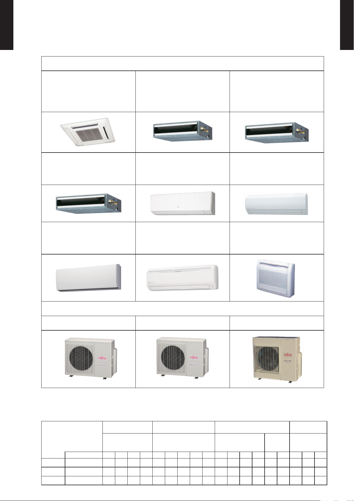
OUTDOOR
AUU7RLF
AUU9RLF
AUU12RLF
AUU18RLF
ASU7RLF*
ASU9RLF*
ASU12RLF*
*:AOU36RLXFZ1 is not connectable.
AOU18RLXFZ
AOU24RLXFZ
ARU7RLF
ARU9RLF
ARU12RLF
ASU9RLS2*
ASU12RLS2*
ASU15RLS2*
AOU36RLXFZ1
ARU18RLF
ASU18RLF
ASU24RLF
ARU24RLF
AGU9RLF
AGU12RLF
AGU15RLF
Page 2

1. INDOOR UNIT
COMPACT
CASSETTE TYPE :
AUU7RLF
AUU9RLF
AUU12RLF
AUU18RLF
WALL MOUNTED TYPE :
ASU7RLF1
ASU9RLF1
ASU12RLF1
ASU7RLF*
ASU9RLF*
SLIM DUCT TYPE :
ARU7RLF
ARU9RLF
ARU12RLF
ARU18RLF
ARU24RLF
FLOOR TYPE :
AGU9RLF
AGU12RLF
AGU15RLF
ASU12RLF*
ASU9RLS2*
ASU12RLS2*
ASU15RLS2*
ASU18RLF
ASU24RLF
*:AOU36RLXFZ1 is not connectable.
DTR_MU041E_02
2015.03.19
Page 3

CONTENTS
MULTI TYPE
2, 3, 4 ROOMS TYPE
MULTI TYPE
2, 3, 4 ROOMS TYPE
1. INDOOR UNIT
1. FEATURES
1-1. INDOOR UNIT
1-1-1. COMPACT CASSETTE TYPE
1-1-2. SLIM DUCT TYPE
1-1-3. WALL MOUNTED TYPE
1-1-4. FLOOR TYPE
1-2. LINE UP
........................................................................................................... 01 - 01
.................................................................................................... 01 - 01
...................................................................................... 01 - 02
............................................................................................ 01 - 07
.............................................................................................................. 01 - 08
2. REMOTE CONTROLLER
2-1. WIRELESS REMOTE CONTROLLER
2-2. WIRED REMOTE CONTROLLER
(For Compact cassette type, Slim duct type)
3. SPECIFICATIONS
3-1. COMPACT CASSETTE TYPE
3-2. SLIM DUCT TYPE
3-3. WALL MOUNTED TYPE
3-4. FLOOR TYPE
........................................................................................... 01 - 30
............................................................................................. 01 - 31
.................................................................................. 01 - 32
..................................................................................................... 01 - 36
................................................................... 01 - 01
........................................................................... 01 - 03
...........................................................................01 - 11
............................................................01 - 11
........................................... 01 - 24
......................................................................... 01 - 30
4. DIMENSIONS
4-1. COMPACT CASSETTE TYPE
4-2. SLIM DUCT TYPE
4-3. WALL MOUNTED TYPE
4-4. FLOOR TYPE
5. WIRING DIAGRAMS
5-1. COMPACT CASSETTE TYPE
5-2. SLIM DUCT TYPE
5-3. WALL MOUNTED TYPE
5-4. FLOOR TYPE
...................................................................................................... 01 - 37
......................................................................... 01 - 37
............................................................................................. 01 - 39
.................................................................................. 01 - 44
..................................................................................................... 01 - 52
..................................................................................... 01 - 53
......................................................................... 01 - 53
............................................................................................. 01 - 54
.................................................................................. 01 - 55
..................................................................................................... 01 - 59
6. AIR VELOCITY AND TEMPERATURE DISTRIBUTIONS
6-1. COMPACT CASSETTE TYPE
6-2. SLIM DUCT TYPE with Auto louver grille kit
6-3. WALL MOUNTED TYPE
6-4. FLOOR TYPE
..................................................................................................... 01 - 86
........................................................................ 01 - 60
............................................ 01 - 66
.................................................................................. 01 - 76
01 - 60
7. FAN PERFORMANCE CURVE
7-1. SLIM DUCT TYPE
8. AIRFLOW
............................................................................................................... 01 - 97
............................................................................................. 01 - 87
............................................................. 01 - 87
Page 4

CONTENTS
MULTI TYPE
2, 3, 4 ROOMS TYPE
MULTI TYPE
2, 3, 4 ROOMS TYPE
1. INDOOR UNIT
9. NOISE LEVEL CURVE
9-1. COMPACT CASSETTE TYPE
9-2. SLIM DUCT TYPE
9-3. WALL MOUNTED TYPE
9-4. FLOOR TYPE
9-5. SOUND LEVEL CHECK POINT
........................................................................................... 01 - 101
....................................................................................................01 - 111
................................................................................ 01 - 99
......................................................................... 01 - 99
................................................................................ 01 - 104
....................................................................01 - 113
10. ELECTRIC CHARACTERISTICS
11. SAFETY DEVICES
12. EXTERNAL INPUT & OUTPUT
12-1. EXTERNAL INPUT
12-2. EXTERNAL OUTPUT
13. FUNCTION SETTINGS
13-1. INDOOR UNIT (setting by jumper wire)
13-2. INDOOR UNIT (setting by wireless remote controller)
13-2-1. UTY-LNHUM/AR-RAH1U
.........................................................................................01 - 117
...........................................................01 - 118
...........................................................................................01 - 118
..................................................................................... 01 - 120
.............................................................................. 01 - 124
........................................................................ 01 - 126
.......................................................01 - 116
.................................................... 01 - 124
........................ 01 - 125
13-2-2. AR-RED1U
13-2-3. AR-REG1U
............................................................................................... 01 - 131
............................................................................................... 01 - 136
13-3. INDOOR UNIT (setting by wired remote controller)
13-3-1. UTY-RNNUM
............................................................................................ 01 - 142
13-4. INDOOR UNIT (setting by simple remote controller)
13-5. FUNCTION DETAILS
13-6. WIRED REMOTE CONTROLLER
13-7. SIMPLE REMOTE CONTROLLER
14. OPTIONAL PARTS
14-1. CONTROLLER
14-2. CASSETTE GRILLE
14-3. OTHERS
........................................................................................................... 01 - 162
................................................................................................ 01 - 160
...................................................................................... 01 - 149
................................................................ 01 - 154
............................................................... 01 - 157
....................................................................................... 01 - 160
....................................................................................... 01 - 161
15. INSTALLATION PRECAUTIONS
15-1. INDOOR UNIT INSTALLATION PRECAUTIONS
.............................. 01 - 141
............................ 01 - 145
....................................................... 01 - 165
...................................... 01 - 165
Page 5
FEATURES1.
+
2 stage
22-7/16in. (570mm)
22-7/16in. (570mm)
27-9/16in. (700mm)
A
B
C
D
2
3
1
INDOOR UNIT1-1.
MULTI TYPE
2, 3, 4 ROOMS TYPE
MODELS : AUU7RLF, AUU9RLF, AUU12RLF, AUU18RLF
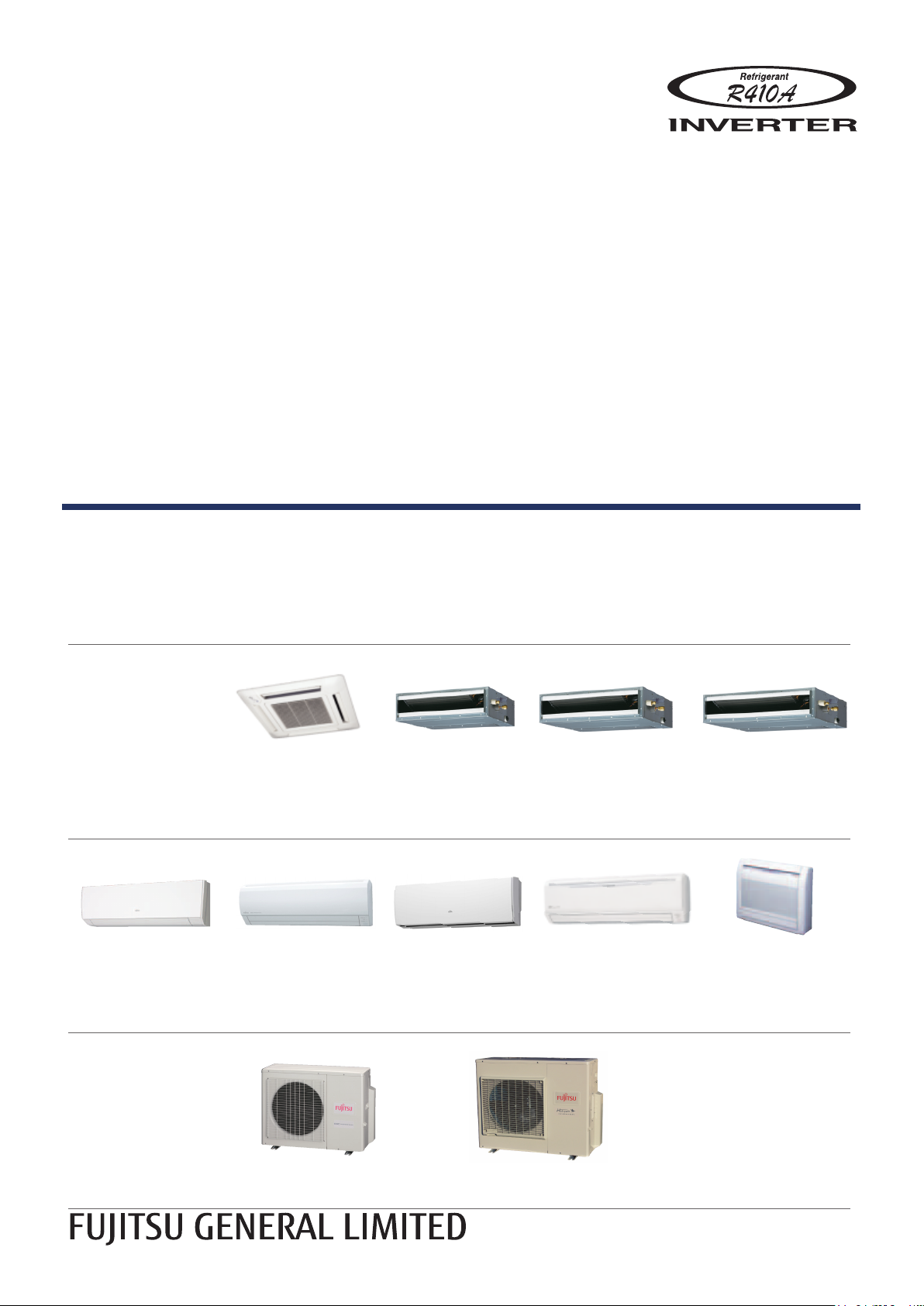
COMPACT CASSETTE TYPE1-1-1.
FEATURES
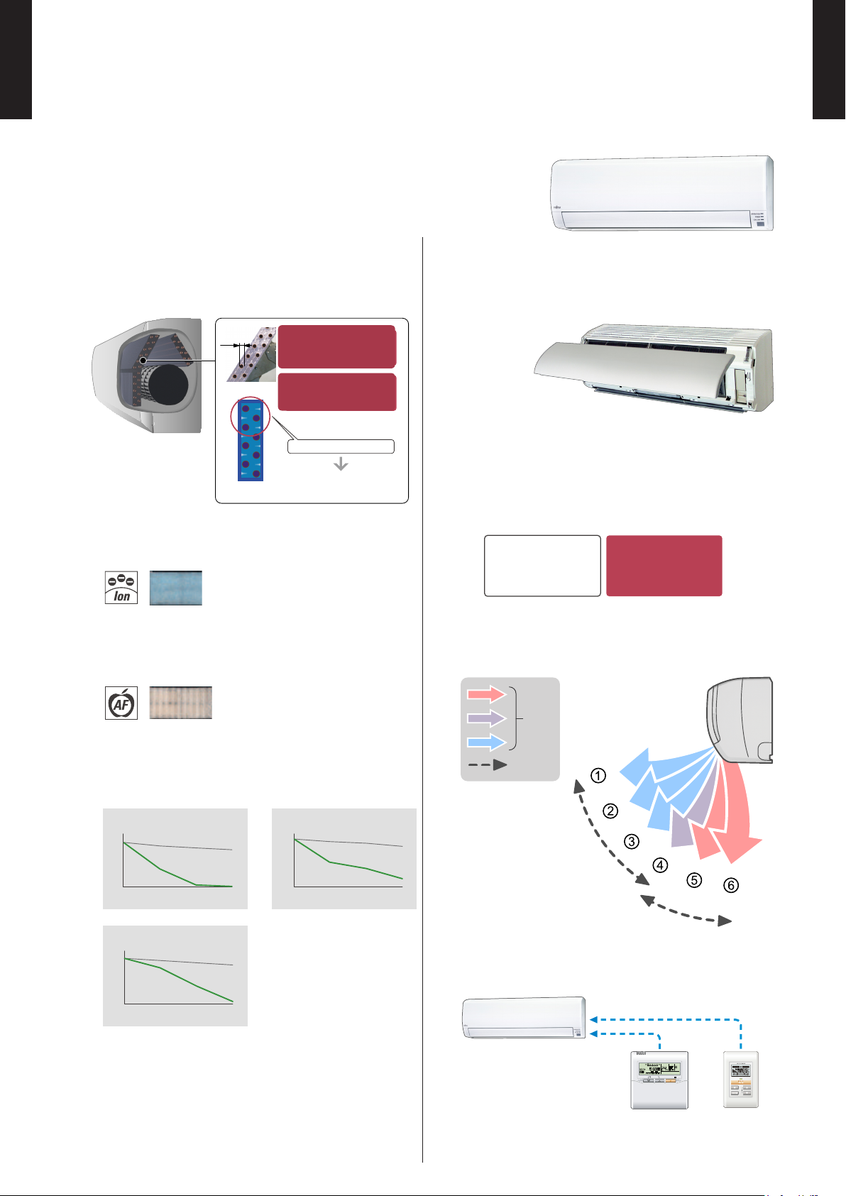
2-stage turbo fan
z
Quiet quality
z
Optimization of wing form (laminar
Wind
velocity
Fast
Slow
High efciency design by 2 stage structure
Previous turbo fan
In the case of a
conventional fan, the air
outlet range was narrow
as the air ow moved to
the motor side which
meant the velocity of air
passing through the heat
exchanger was uneven.
2-stage turbo fan
A evenly spread air distribution across
the heat exchanger is possible due
to the new 2 stage turbo fan which
produces two separate air ow
streams.
1-stage
2-stage
Heat exchange
efciency:
20%UP
wing type) and wing number (7 blades
each)
Designed by CFD- analysis (uid) simulations
Laminar wing
Airow runs through smoothly
along the laminar wing
No airow separation
Quiet
Spin direction
Airow direction
Quiet
Adoption of laminar wing
MULTI TYPE
2, 3, 4 ROOMS TYPE
Easy maintenance
z
Maintenance of fan motor and fan
Maintenance of the fan motor and fan can be done easily after taking off the panel as the bell mouth of the fan
can be removed easily.
A : Fan motor B : 2-stage turbo fan
C : Bell-mouth D : Panel
Long life lter
: standard equipment
Adaptation of transparent drainage parts
During installation, maintenance and operation, the drain pump and
kit can be checked easily.
Compact design
z
Grille cover
Easy installation by taking off ceiling panel of 23-5/8in. x 23-5/8in.(600mm x 600mm) size
High lift drain pump
z
- (01 - 01) -
Page 6
MULTI TYPE
Height
Drain pump built-in
7-13/16 in.
(198mm)
Max.
33-7/16 in.
(850mm)
0
[in.WG (Pa )]
Air flow rate
Static pressure range
[CFM (m3/h)]
0.36 (90)
2, 3, 4 ROOMS TYPE
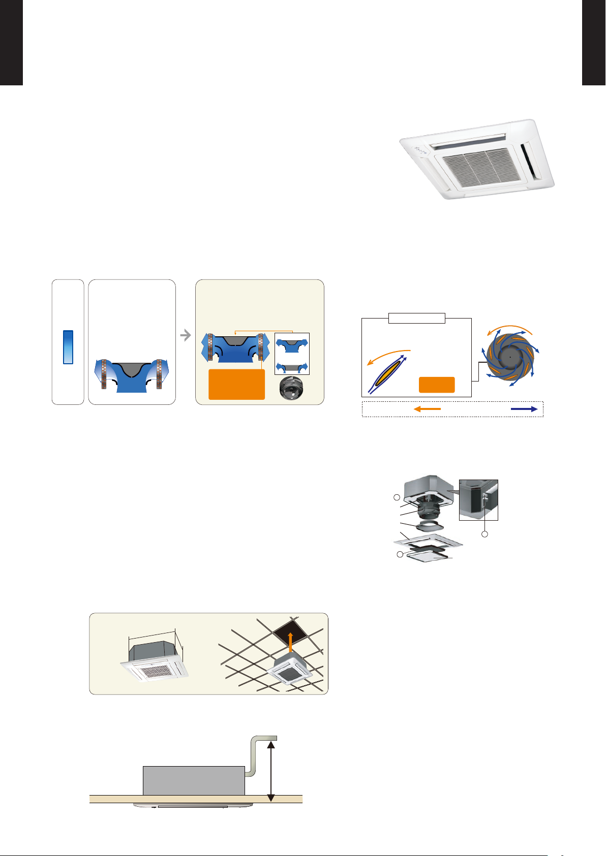
MODELS : ARU7RLF, ARU9RLF, ARU12RLF, ARU18RLF, ARU24RLF
SLIM DUCT TYPE1-1-2.
MULTI TYPE
2, 3, 4 ROOMS TYPE
Slim design and wide range of static
pressure for exible installation.
FEATURES
Slim design
z
This model is slim design, it can install at
the place where a ceiling is narrow.
Drain por t
Drain pump
Compact design
z
Condensate lift-up to 33-7/16in. (850mm)
Drain hose is standard accessory
Selectable with a wide range of
z
static pressure
Air - intake
z
Air intake direction can be selected to
match the installation site.
Bottom side Back side
Flexible installation
z
Ceiling concealed
Wall concealed
By using DC fan motor, it is possible
to change of static pressure range 0 to
0.36in. WG (0 to 90Pa). The change of
static pressure range is possible by remote
controller.
* 24 model is 0 to 0.20in.WG
(0 to 50Pa)
- (01 - 02) -
Filter (Accessory)
z
Filter (ARU07/09/12/18: 2pcs.)
ARU24: 3pcs.)
Page 7
MULTI TYPE
“MIN. HEAT”
Button ON
Indoor unit
operation START
68
°F
(20°C)
50
°F
(10°C)
2, 3, 4 ROOMS TYPE
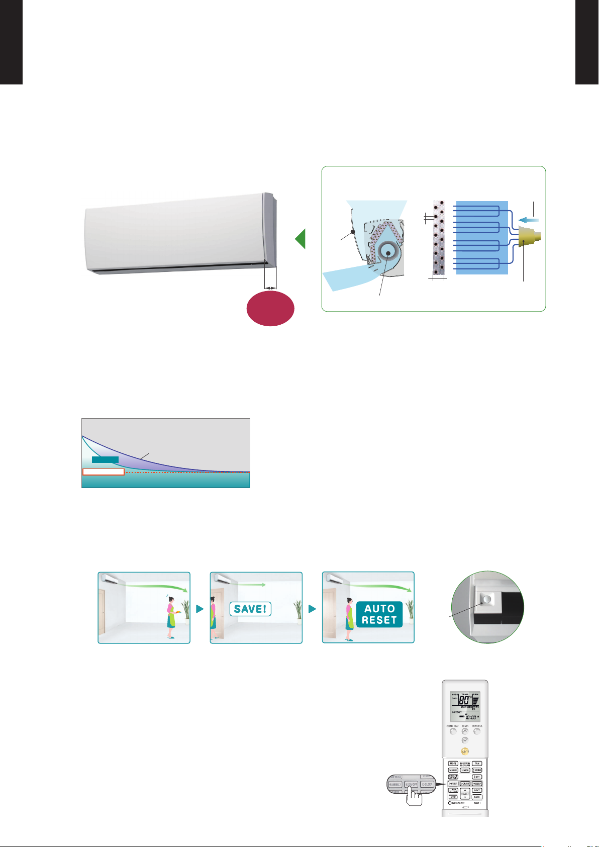
MODELS : ASU7RLF1, ASU9RLF1, ASU12RLF1
FEATURES
WALL MOUNTED TYPE 1-1-3.
MULTI TYPE
2, 3, 4 ROOMS TYPE
High efcient compact design
z
Makin g the tu be thin:
0.276inch (7mm)
Thin:
Volume reduct ion of heat
exchanger:
Quiet operation
z
▼
0.197inch (5mm)
30%
More comfortable airow
z
INDOOR UNIT
Airow mode can be set in 4 steps and more detailed airow setting is possible.
21dB only at cooling operation (22dB at heating operation).
Fan speed Noise level
dB(A)
Quiet
21
(ASU7/9/12RLF1)
MIN. HEAT Operation
z
*Only available with Wireless RC.
The room temperature can be set to go no lower than 50°F (10°C),
thus ensuring that the room does not get too cold when not occupied
Caution)
When the room temperature is higher than 50°F (10°C), “ •
temperature at 50°F (10°C) when the temperature drops below 50°F (10°C).
MIN. HEAT
When “ •
Powerful operation
z
” operation stops, the room set temperature quickly returns to the preset temperature.
*Only available with Wireless RC.
MIN. HEAT
” operation does not start. Operation star ts and maintains the room
20 minutes continuous operation by maximum airow and maximum compressor speed is
possible. Rapid cooling and heating makes the room comfortable quickly.
- (01 - 03) -
Page 8
MULTI TYPE
Ø5
SET TEMP.
START/STOP
2, 3, 4 ROOMS TYPE
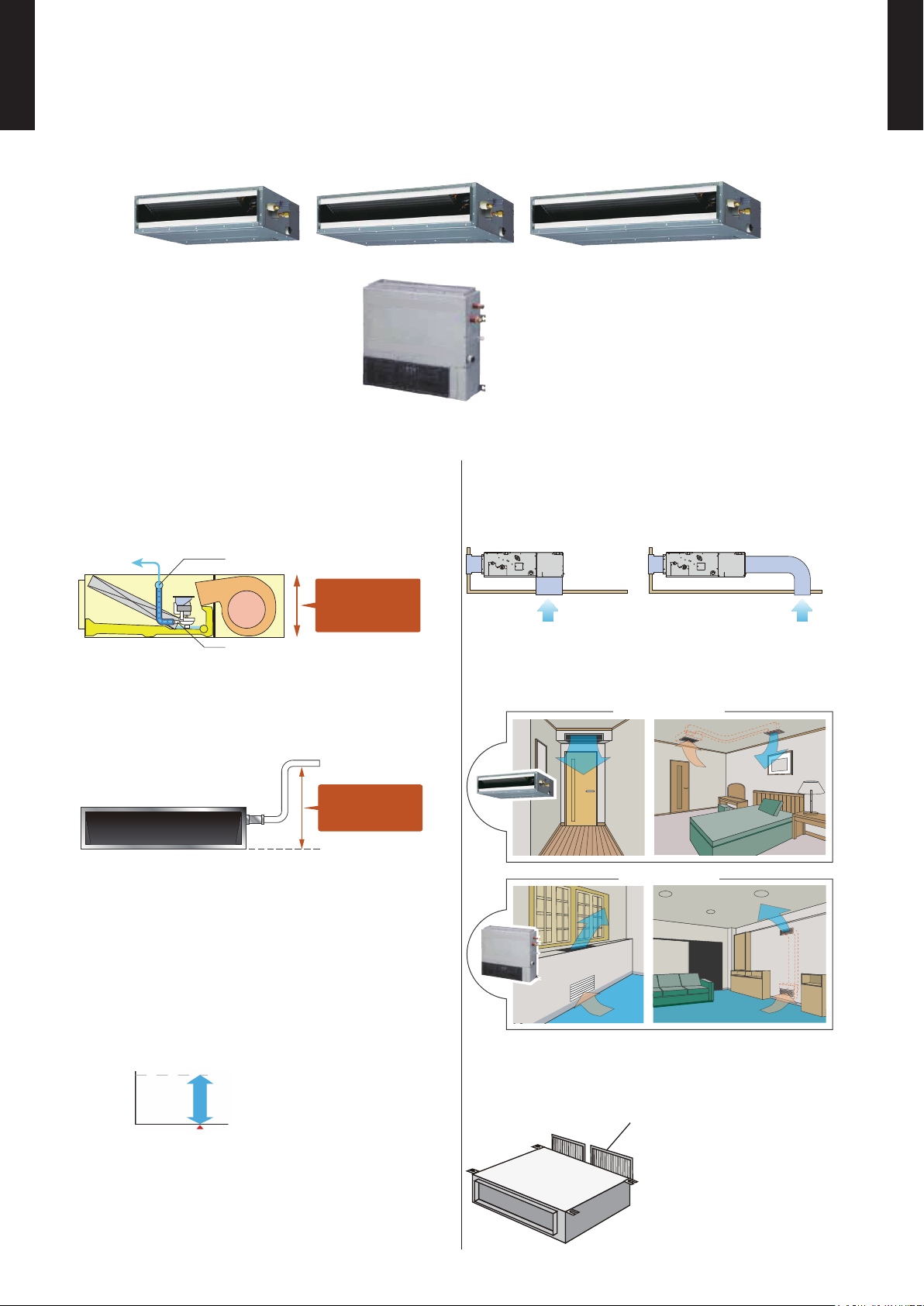
MODELS : ASU7RLF, ASU9RLF, ASU12RLF
MULTI TYPE
2, 3, 4 ROOMS TYPE
Compact and Stylish design indoor unit
FEATURES
High density heat transfer tube
z
arrangement
Easy maintenance
z
Makin g the tu be
0.276inch (7mm)
Filter features
z
Thin:
Volume reduct ion of heat
exchanger:
Even temperature
Improved the heat
exchang er effectiveness
▼
0.197inch (5mm)
30%
Long-life*
Ion deodorization lter
The lter deodorizes by powerfully decomposing absorbed
odors using the oxidizing and reducing effects of ions
generated by the ultra-ne particle ceramic.
*The l ter can be used for approx. 3 yea rs if it is wa shed und er water to restore
it's su rfac e action when it is dirty.
Apple-catechin lter
Fine dust, invisible mold spores, and harmful microorganisms
are absorbed onto the lter by static electricity, and further
growth is inhibited and deactivated by the polyphenol
ingredient extracted from apples.
Removable &
washable
panel
Dry operation
Dry operation removes moisture and keeps the air conditioner
clean.
Quiet operation
z
Cooling mode (07/09/12 TYPE)
Fan speed
Quiet
Auto swing louvre
z
The Auto Swing Louvre function ensures that the air direction
corresponds to the mode selected.
Step
Swing
Noise level
25dB
(A)
Deodorizing effect (Odor reduction rate)
(ppm)
160
120
80
40
0
0 30 60 120
(ppm)
160
120
80
40
0
0 30 60 120
Ammonia
With no lter
New lter
(mi n.)
Hydrogen sulfate
With no lter
New lter
(mi n.)
(ppm)
160
120
80
40
0
Testing organizati on :
Environmental S anitar y Inspection
Center
Test method :
Deodorization Test
Trimethylamine
With no lter
New lter
0 30 60 120
(mi n.)
- (01 - 04) -
Swing (Cooling)
Swing (Heating)
Wired control compatible
z
*
Wired and wireless remote
controller are acceptable.
* Optional comm unicat ion kit i s
necce sary f or the ins tallat ion.
Wired remote
controller
Simple remote
controller
Page 9
MULTI TYPE
Large fan
Open
panel
Distributor
4-path
Refrigerant
Large intake
Big open panel and High density multi path heat
exchanger
Thin and slim design is realized by Ø5mm heat
exchanger and high efficiency wind blower.
H11-1/8 × W34-1/4 × D7-5/16 in.
(H282 × W870 × D185 mm)
7-5/16 in.
(185mm)
Ø3/16in.
(Ø5mm)
13/16 in.
(20mm)
Powerful
Setting temp.
Normal mode
Time
Temperature
Energy saving operation by detecting someone’s movement
Human
sensor
2, 3, 4 ROOMS TYPE
MODELS : ASU9RLS2, ASU12RLS2, ASU15RLS2
FEATURES
Thin & Slim design
z
MULTI TYPE
2, 3, 4 ROOMS TYPE
Powerful operation
z
*Only available with Wireless RC.
20 minutes continuous operation by maximum airow and maximum compressor speed is
possible. Rapid cooling and heating makes the room comfortable quickly.
Example : Cooling operation
Energy saving control
z
Human sensor catches movements of people in a room, and operates with lower capacity when the room is
empty. When people come back to the room, it automatically returns to previous operating mode.
*Only available with Wireless RC.
5 Mode timer (ON/OFF/Weekly/Program/Sleep)
z
Weekly timer can be easily set by wireless remote controller.
ON, OFF can be set up to 4 times in 1 day and up to 28 times in 1 week.
For other modes, program timer and sleep timer can be also selected by one push.
*Only available with Wireless RC.
- (01 - 05) -
Page 10
MULTI TYPE
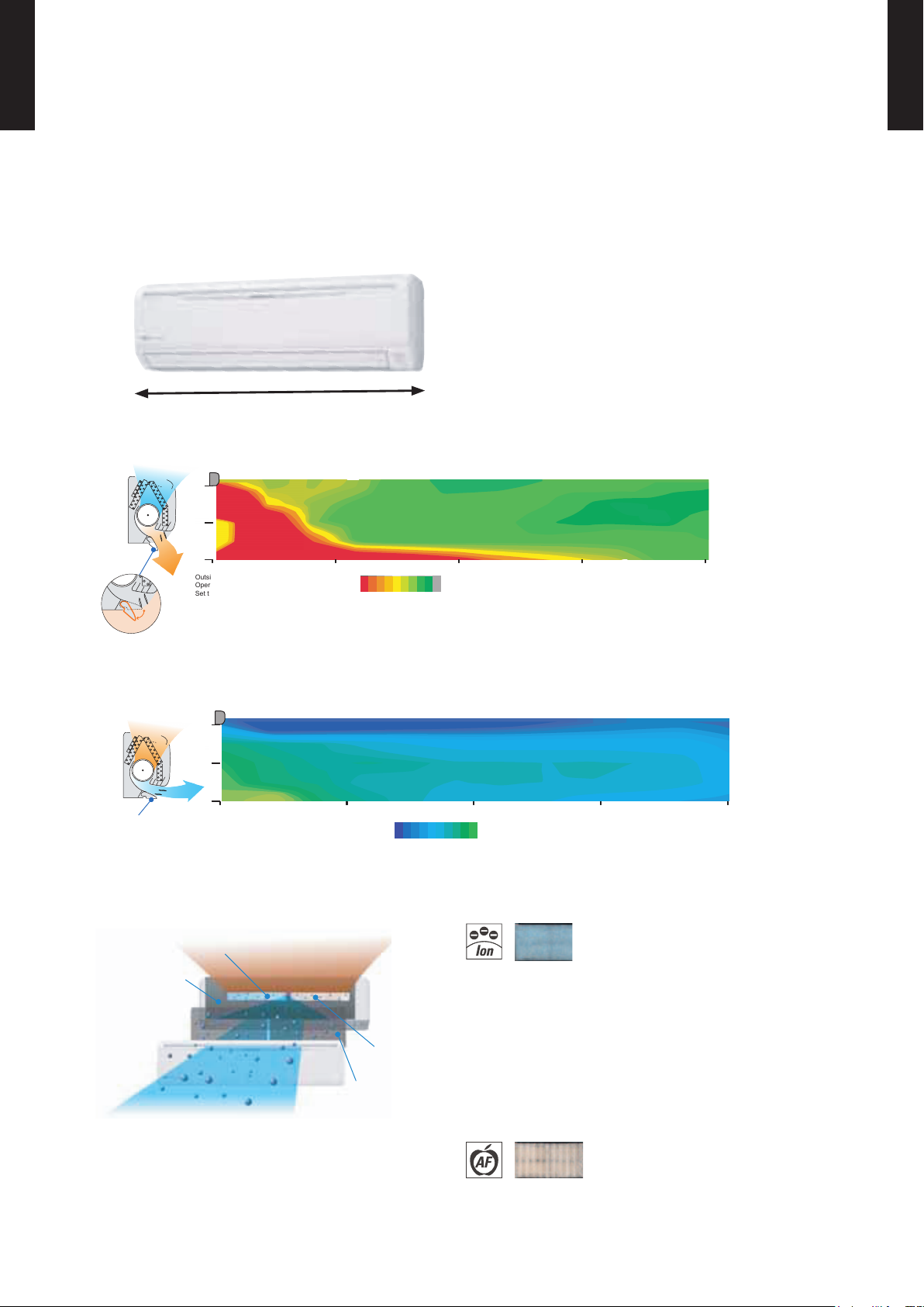
Outside air conditions: 35.6oF (2o C) 60%
( F)
Operation contents: Heating
Set temperature (Max set temp)
86
o
F (30oC), Air flow Hi
o
( C)
o
Vertical flap : Downward
Horizontal flap : Center
Power diffuser
(full open)
8492 90 88 86
2933 32 31 30
46
o
(24/30)
16
7 (2.1)
3 (1)
0
10 (3) 20 (6) 30 (9) 40 (12)
ft.(m)
ft.(m)
Power diffuser
Outside air conditions: 95oF (35oC) 40%
( F)
Operation contents: Cooling
Set temperature (Min set temp)
64
o
F (18oC), Air flow Hi
o
Vertical flap : Upward
Horizontal flap : Center
6458 60 62
( C)
o
1815 16 17
7 (2.1)
3 (1)
0
ft.(m)
10 (3) 20 (6) 30 (9) 40 (12)
ft.(m)
Organic coating fin used
heat exchanger
Pre Filter
Antibacterial deodorizing pre-filter with special ceramic powder
Ion Deodorization Filter
Apple-catechin
Filter
2, 3, 4 ROOMS TYPE
MODELS : ASU18RLF, ASU24RLF
MULTI TYPE
2, 3, 4 ROOMS TYPE
Simple & Elegant Appearance Design
FEATURES
Compact & Slim design
z
39-5/16in. (998 mm)
“Vertical airow” provides powerful oor level heating
z
“Horizontal airow” does not blow cool air directly at thez occupants in the room
Air conditioner lter features
z
Easy maintenance
z
Simplication of drain pan cleaning
improves maintenance-ability.
Long-life*
Ion deodorization lter
The lter deodorizes by powerfully decomposing
absorbed odors using the oxidizing and reducing
effects of ions generated by the ultra-ne-particle
ceramic.
(*The lter can be used for approx. 3 years if it is washed
under water to restore its surface action when it is dirty.)
Using different lters at both sides
É
Apple-catechin lter
Fine dust, invisible mold spores, and harmful
microorganisms are absorbed onto the lter by
static electricity, and further growth is inhibited and
deactivated by the polyphenol extracted from apples.
- (01 - 06) -
Page 11
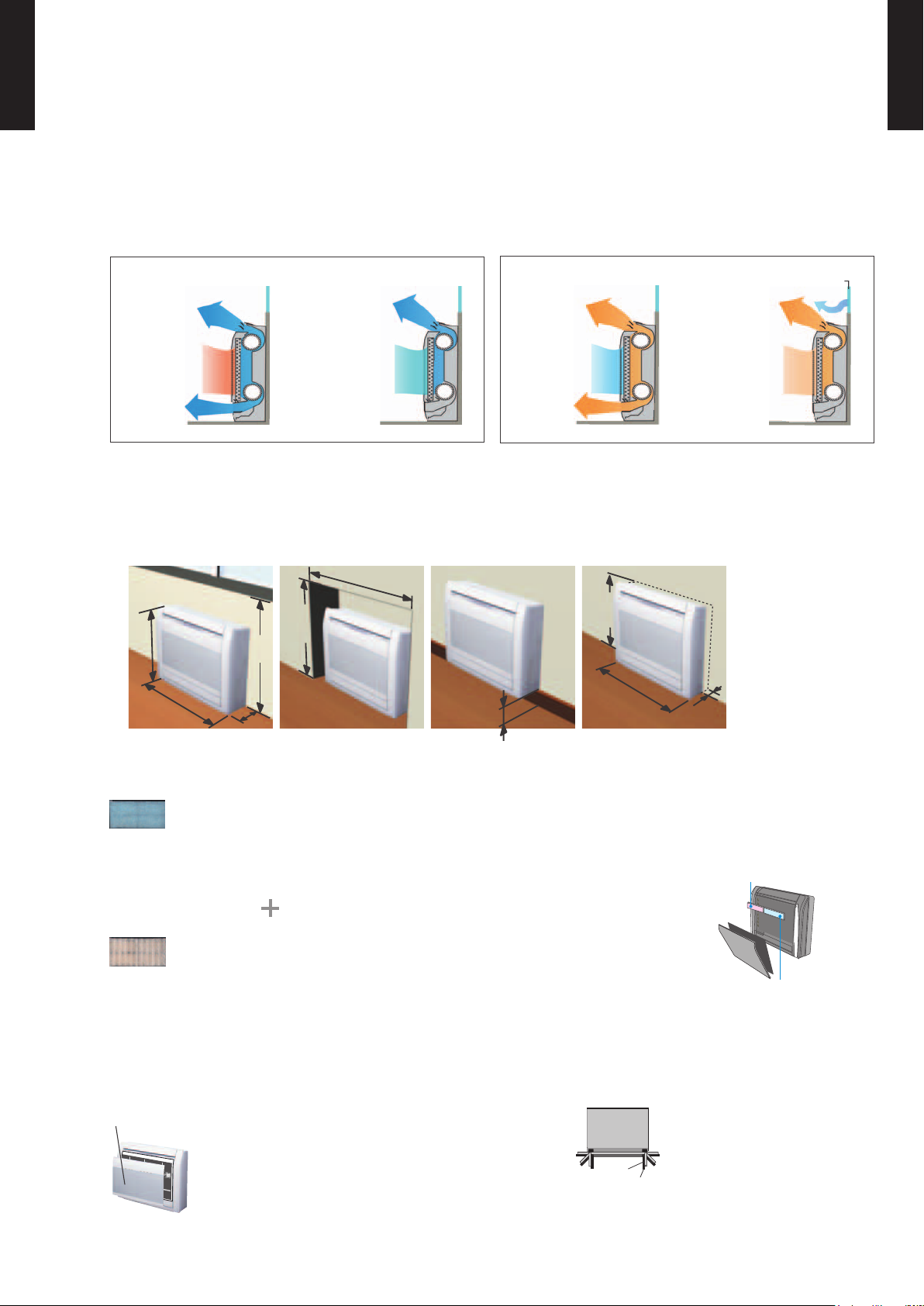
MULTI TYPE
Cooling
at operation
start
Prevents cold air
from falling
at stable
operation
at operation
start
Heating WindowPrevents cold
draft from
window
at stable
operation
Beneath
standard window
Standard concave
portion
Wall
Half concealed
Min.
27-9/16
(700)
Min.
23-1/4
(590)
Max.
3-1/8
(80)
Min.
28-3/4
(730)
Min.37 (940)
Max.
5-7/8
(150)
23-5/8
(600)
29-1/8
(740)
7-7/8
(200)
27-9/16
(700)
Removable panel
Back view
Drain hose
Piping
1
6
2
5
3
4
Apple-catechin
Filter
Ion Deodorization
Filter
2, 3, 4 ROOMS TYPE
MODELS : AGU9RLF, AGU12RLF, AGU15RLF
FEATURES
FLOOR TYPE 1-1-4.
2-Fan & Wide airow
z
Flexible & easy installation
z
Unit: in. (mm)
MULTI TYPE
2, 3, 4 ROOMS TYPE
Filter features
z
ion deodorization lter
The lter deodorizes by powerfully decomposing absorbed odors using the oxidizing and reducing
effects of ions generated by the ultra-ne-particle ceramic.
Using different lters at both sides
Apple-catechin lter
Apple-catechin lter uses static electricity to clean ne particles and dust in
the air.
Easy maintenance
z
Removable and washable panel
Flexible piping connection
z
6 direction of drain & piping
- (01 - 07) -
Page 12
LINE UP1-2.
MULTI TYPE
2, 3, 4 ROOMS TYPE
MODEL
INDOOR UNIT
MULTI TYPE
2, 3, 4 ROOMS TYPE
AUU7RLF
AUU9RLF
AUU12RLF
ARU7RLF
ARU9RLF
ARU12RLF
AUU18RLF
ARU24RLF ASU7RLF1
ASU9RLF1
ASU12RLF1
ASU9RLS2
ASU12RLS2
ASU18RLF
ASU24RLF
ASU15RLS2
ARU18RLF
ASU7RLF
ASU9RLF
ASU12RLF
AGU9RLF
AGU12RLF
AGU15RLF
OUTDOOR UNIT
AOU18RLXFZ AOU24RLXFZ AOU36RLXFZ1
Indoor units that can be connected to each outdoor unit
z
: Connectable / -: Not connectable
●
COMPACT
CASSETTE
OUTDOOR
AUU7-18 RLF ARU7-24RLF
Btu Class 7 9 12 18 7 9 12 18 24 7 9 12 15 18 24 9 12 15
2 Rooms AOU18RL XFZ
3 Rooms AOU24RL XFZ
4 Rooms AOU36RLXFZ1
*:AOU36RLXFZ1 is not connectable.
● ● ● - ● ● ● - - ● ● ● - - - ● ● -
● ● ● ● ● ● ● ● - ● ● ● ● ● - ● ● ●
● ● ● ● ● ● ● ● ● ● ● ● - ● ● ● ● ●
SLIM DUCT WALL MOUNTED FLOOR
ASU7-12 RLF *
ASU7-12RLF1
ASU9-15RLS2*
- (01 - 08) -
ASU18 -
24RLF
AGU9-15RLF
Page 13
INDOOR UNIT CONNECTION PATTERNS
2 Rooms
MULTI TYPE
2, 3, 4 ROOMS TYPE
z
AOU18RLXFZ
No. room 1 room 2 total
1 7 7 14
2 7 9 16
3 7 12 19
4 9 9 18
5 9 12 21
Notes) 7: 7,000Btu/h, 9: 9,000Btu/h, 12: 12,000Btu/h models
3 Rooms
z
AOU24RLXFZ
No. room 1 room 2 room 3 total
1 7 7 - 14
2 7 9 - 16
3 7 12 - 19
4 7 15 - 22
5 7 18 - 25
6 9 9 - 18
7 9 12 - 21
8 9 15 - 24
9 9 18 - 27
10 12 12 - 24
11 12 15 - 27
12 7 7 7 21
13 7 7 9 23
14 7 7 12 26
15 7 9 9 25
16 9 9 9 27
MULTI TYPE
2, 3, 4 ROOMS TYPE
Notes) 7: 7,000Btu/h, 9: 9,000Btu/h, 12: 12,000Btu/h, 15: 14,000Btu/h, 18: 18,000Btu/h models
- (01 - 09) -
Page 14
4 Rooms
MULTI TYPE
2, 3, 4 ROOMS TYPE
z
MULTI TYPE
2, 3, 4 ROOMS TYPE
AOU36RLXFZ1
No. room 1 room 2 room 3 room 4 total
1 18
Ü
1
18
Ü
1
- - 36
2 7 7 15 - 29
3 7 7 18 - 32
4 7 7 24 - 38
5 7 9 12 - 28
6 7 9 15 - 31
7 7 9 18 - 34
8 7 12 12 - 31
9 7 12 15 - 34
10 7 12 18 - 37
11 9 9 9 - 27
12 9 9 12 - 30
13 9 9 15 - 33
14 9 9 18 - 37
15 9 12 12 - 33
16 9 12 15 - 36
17 9 12 18 - 39
18 12 12 12 - 36
19 12 12 15 - 39
20 7 7 7 7 28
21 7 7 7 9 30
22 7 7 7 12 33
23 7 7 7 15 36
Ü
24 7 7 7 18
2
39
25 7 7 9 9 32
26 7 7 9 12 35
27 7 7 9 15 38
28 7 7 12 12 38
29 7 9 9 9 34
30 7 9 9 12 37
31 9 9 9 9 36
Notes) 7: 7,000Btu/h, 9: 9,000Btu/h, 12: 12,000Btu/h, 15: 14,000Btu/h, 18: 18,000Btu/h, 24: 24,000Btu/h models
1: The optional kit "K9FZ1818 (UTP-MU36A2)" shall be necessary for the dual zone system "18+18".
Ü
2: Wall mounted type ASU18RLF can not be connected in this combination.
Ü
- (01 - 10) -
Page 15
REMOTE CONTROLLER2.
60min.
2°F (1°C)
4°F (2°C)
Timer setting
2°F (1°C)
4°F (2°C)
6°F (3°C)
8°F (4°C)
30min.
60min.
90min.
Timer setting
A B C D
A B
C
D
Mixed-up
I.U. I.U. I.U. I.U.
I.U. I.U. I.U. I.U.
After code change
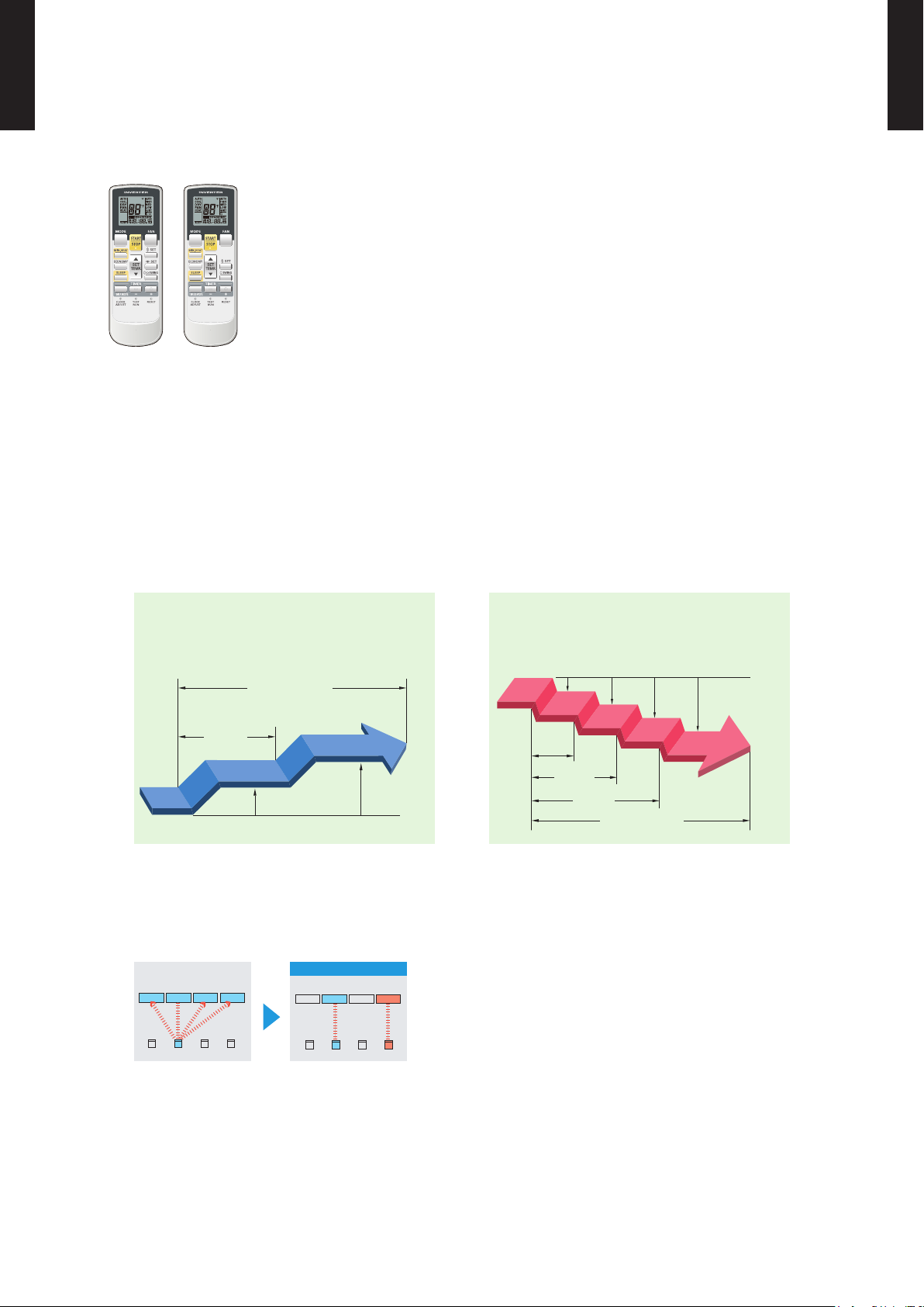
WIRELESS REMOTE CONTROLLER2-1.
MULTI TYPE
2, 3, 4 ROOMS TYPE
MODEL: UTY-LNHUM/AR-RAH1U
FEATURES
4 mode timer setup available (ON / OFF / PROGRAM /SLEEP). ●
Can be used jointly with wired remote controllers . ●
Easy to change custom code (max. 4 custom codes) by button operation. ●
Built-in timers
z
Select from four different timer programs (ON/OFF/PROGRAM/SLEEP).
Program timer
z
The program timer operates the ON and OFF timer once within a 24 hour period.
MULTI TYPE
2, 3, 4 ROOMS TYPE
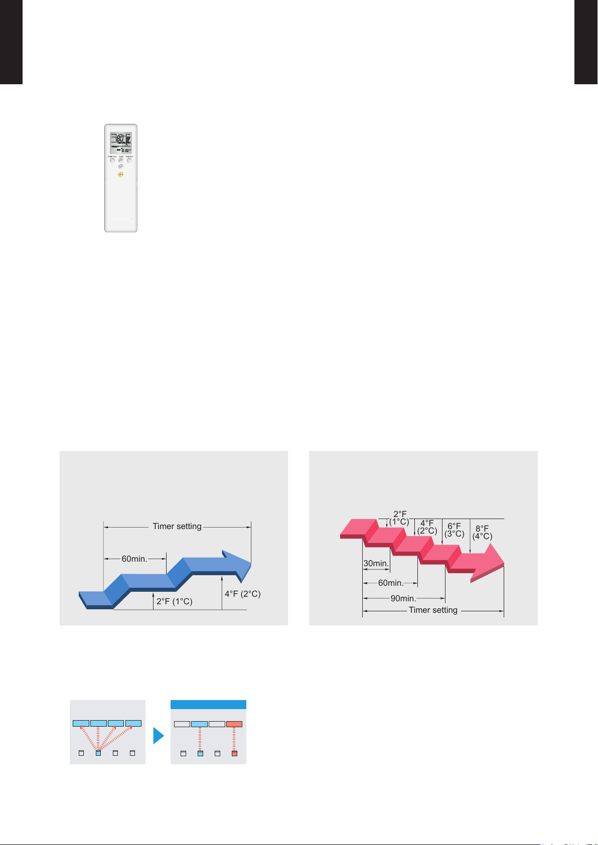
Sleep timer
z
The sleep timer function automatically corrects the temperature thermostat setting according to the
time setting to prevent excessive cooling and heating while sleeping.
Cooling operation / dry operation
When the sleep timer is set, the set temperature
automatically rises 2°F (1°C) every hour. The set
temperature can rise up to a maximum of 4°F (2°C).
Simple function setting
z
Heating operation
When the sleep timer is set, the set temperature
automatically drops 2°F (1°C) every 30 minutes. The
set temperature can drop to a maximum of 8°F (4°C).
Setting of the air conditioner selection function is performed by remote controller.
Switching remote controller custom code
z
Code selector switch eliminates unit
•
being wrongly switched.
(Up to 4 custom codes can be set.)
*I.U.=Indoor unit
- (01 - 11) -
Page 16
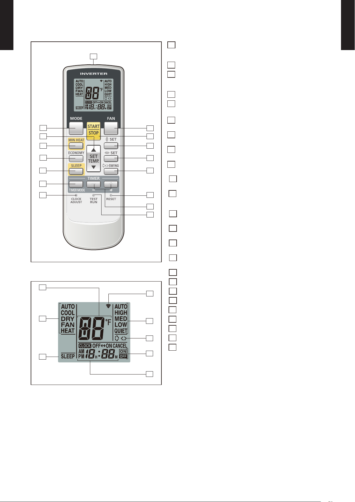
FUNCTIONS (UTY-LNHUM)
2
4
9
3
1
16
15
5
10
13
11
12
14
8
7
6
17
18
19
21
24
23
22
20
MULTI TYPE
2, 3, 4 ROOMS TYPE
MODE button1
Selects the operating mode (AUTO, COOL, DRY, FAN, HEAT).
/Start / end R.C. custom code change. (Max 4 codes)
MULTI TYPE
2, 3, 4 ROOMS TYPE
MIN.HEAT button2
SET TEMP. button ( ▲ / ▼ )3
Sets the indoor temp./ Sets R.C. custom code.
ECONOMY button4
SLEEP button5
Pressed to select sleep timer.
FAN button6
Selects the fan speed (AUTO, HIGH, MED, LOW, QUIET).
START/STOP button7
Pressed to start and stop operation.
SET button (Vertical)8
Air ow direction vertical set button.
SET button (Horizontal)9
Air ow direction horizontal set button.
SWING button10
Air ow direction swing button.
TIMER MODE button11
Pressed to select the timer mode. (OFF TIMER, ON TIMER,
PROGRAM TIMER, TIMER RESET)
TIMER set ( + / - ) button12
Sets the current time and on-off time.
CLOCK ADJUST button13
Sets the current time.
RESET button14
Used when replacing batteries.
TEST RUN button15
Used when testing the air conditioner after installation.
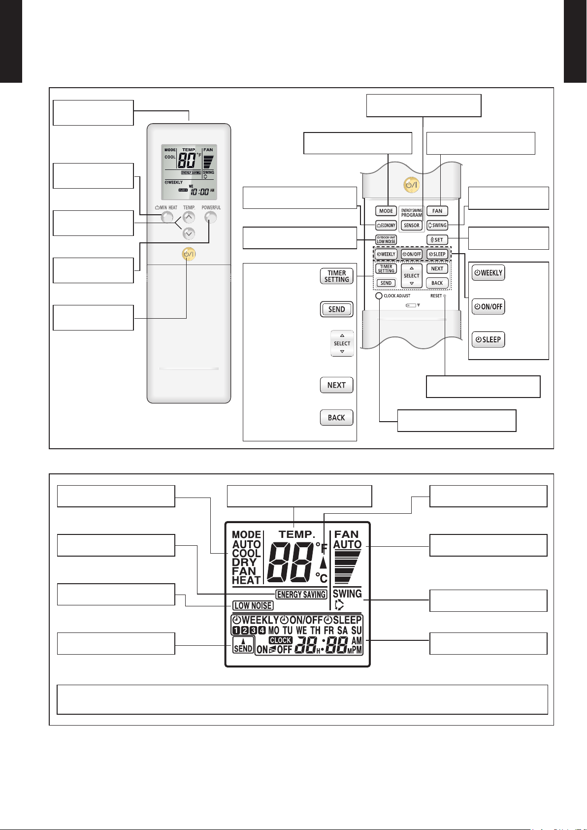
Display panel
Signal transmitter16
Temperature set indicator17
Operating mode indicator18
Sleep indicator19
Transmit indicator20
Fan speed indicator21
Swing indicator22
Timer mode indicator23
Clock indicator24
Note: Functions will be different due to type of indoor unit.
For details, please see operation manual.
- (01 - 12) -
Page 17
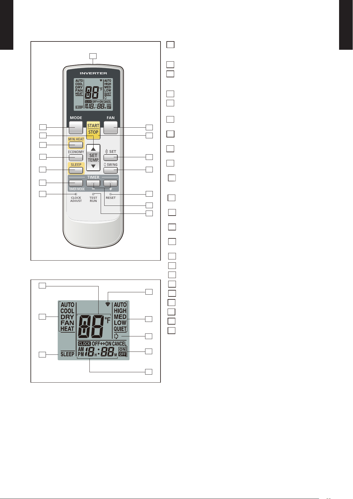
FUNCTIONS (AR-RAH1U)
2
4
9
3
1
15
5
10
13
11
12
14
8
7
6
16
17
18
19
21
23
22
20
MULTI TYPE
2, 3, 4 ROOMS TYPE
MODE button1
Selects the operating mode (AUTO, COOL, DRY, FAN, HEAT).
/Start / end R.C. custom code change. (Max 4 codes)
MULTI TYPE
2, 3, 4 ROOMS TYPE
MIN.HEAT button2
SET TEMP. button ( ▲ / ▼ )3
Sets the indoor temp./ Sets R.C. custom code.
ECONOMY button4
SLEEP button5
Pressed to select sleep timer.
FAN button6
Selects the fan speed (AUTO, HIGH, MED, LOW, QUIET).
START/STOP button7
Pressed to start and stop operation.
SET button (Vertical)8
Air ow direction vertical set button.
SWING button9
Air ow direction swing button.
TIMER MODE button10
Pressed to select the timer mode. (OFF TIMER, ON TIMER,
PROGRAM TIMER, TIMER RESET)
TIMER set ( + / - ) button11
Sets the current time and on-off time.
CLOCK ADJUST button12
Sets the current time.
RESET button13
Used when replacing batteries.
TEST RUN button14
Used when testing the air conditioner after installation.
Signal transmitter15
Display panel
Temperature set indicator16
Operating mode indicator17
Sleep indicator18
Transmit indicator19
Fan speed indicator20
Swing indicator21
Timer mode indicator22
Clock indicator23
Note: Functions will be different due to type of indoor unit.
For details, please see operation manual.
- (01 - 13) -
Page 18
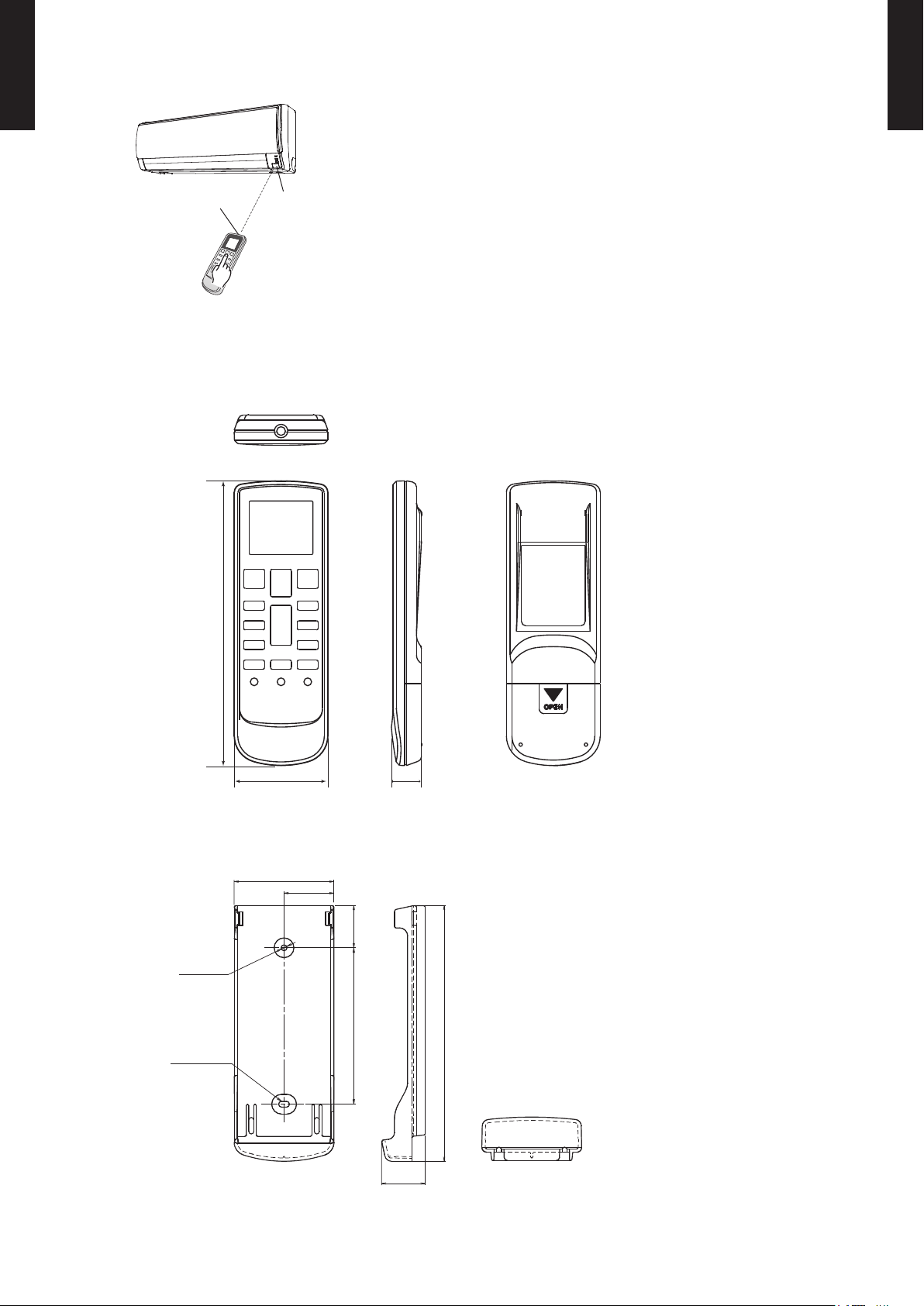
SYSTEM DIAGRAM
6-11/16 (170)
2-3/16 (56)
3/4 (19)
2-3/8 (60.4)
1-3/16 (30.2)
Ø1/8 (3.5)
1/8 x 1/4 (3.5 x 6.5)
(HOLE)
(HOLE)
1-1/16 (26.2)
1 (25.5)
3-3/4 (95)
6-1/16 (154.7)
MULTI TYPE
2, 3, 4 ROOMS TYPE
MULTI TYPE
2, 3, 4 ROOMS TYPE
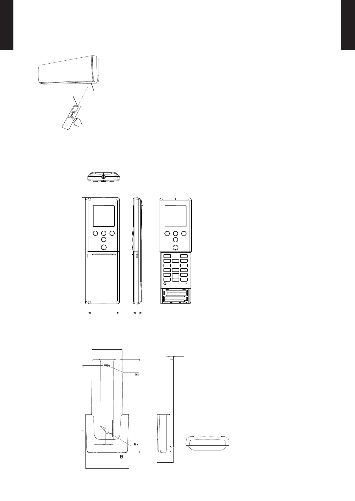
Control signal might not be recognized in following cases: ●
(i) A curtain or a wall, etc. exists between transmitter and receiver.
(ii) There is an instant-start type (inverter type, etc.) uorescent lamp
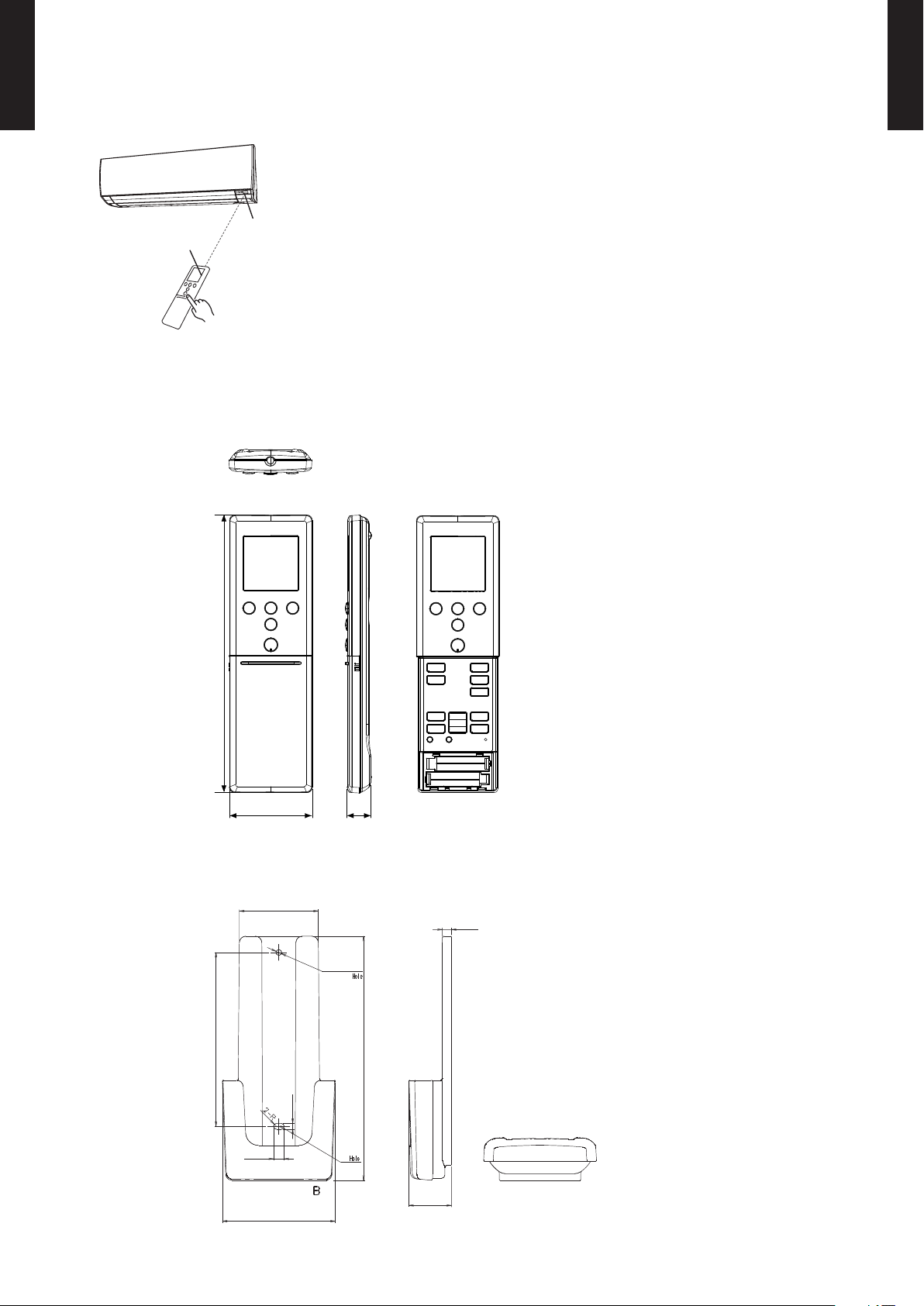
Signal transmitter
Signal receiver
window
in the room.
Air conditioner might not work correctly when strong light hits the ●
signal receiver window. Shut off the direct sunlight and also make
illuminator far away from the receiver window.
DIMENSIONS
Controller
z
Unit : in. (mm)
Top View
Holder
z
Front View Rear View
Side View
Front View Side View Bottom View
- (01 - 14) -
Page 19

MULTI TYPE
2, 3, 4 ROOMS TYPE
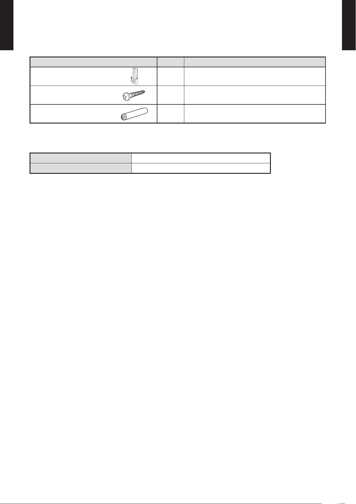
PACKING LIST
Name and shape Quantity Application
MULTI TYPE
2, 3, 4 ROOMS TYPE
Remote controller holder 1
Tapping screw 2
Battery
[ 1.5V (R03 / AAA) ]
SPECIFICATIONS
Dimensions [H x W x D]: in. (mm) 6-11/16 (170) x 2-3/16 (56) x 3/4 (19)
Weight : oz. (g) 3 (85) [w/o batteries]
2 For remote controller
Use as remote controller holder
For remote controller holder installation
- (01 - 15) -
Page 20
MULTI TYPE
60min.
2°F (1°C)
4°F (2°C)
Timer setting
30min.
60min.
90min.
4°F
(2°C)
6°F
(3°C)
8°F
(4°C)
Timer setting
2°F
(1°C)
A B C D
A B
C
D
Mixed-up
I.U. I.U. I.U. I.U.
I.U. I.U. I.U. I.U.
After code change
2, 3, 4 ROOMS TYPE
MODEL: AR-RED1U
FEATURES
5 Mode timer setup
Ü
MULTI TYPE
2, 3, 4 ROOMS TYPE
(ON / OFF / Weekly / Program / Sleep) are possible.
Easy operation.
Ü
Easy to change custom code (max. 4 custom codes) by button
Ü
operation.
Built-in timers
z
Select from ve different timer programs (ON / OFF / Weekly / Program / Sleep).
Weekly timer
z
Weekly timer can be easily set by wireless remote controller.
ON, OFF can be set up to 4 times in 1 day and up to 28 times in 1 week.
Program timer
z
The program timer operates the on and off timer once within a 24 hour period.
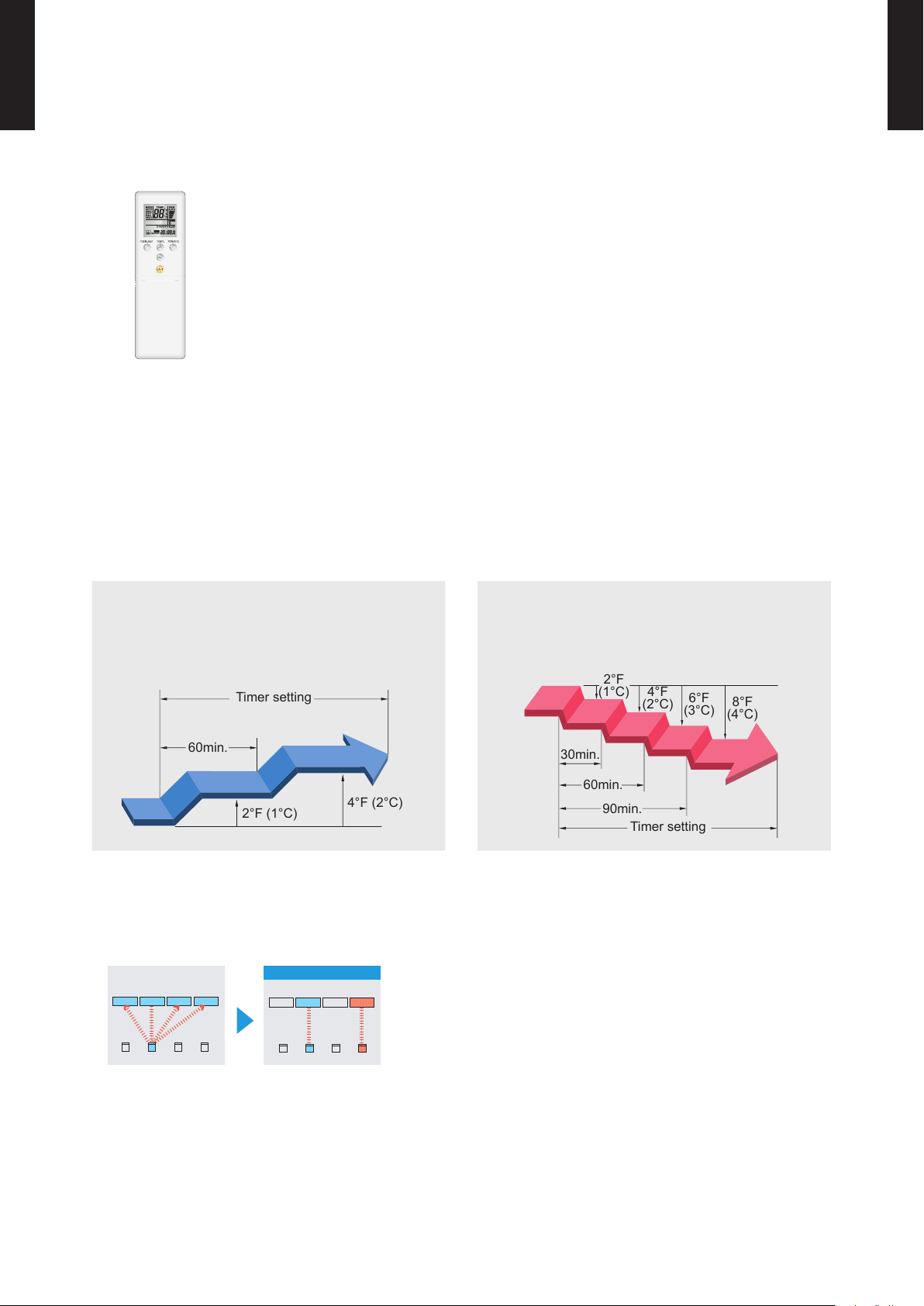
Sleep timer
z
The sleep timer function automatically corrects the temperature thermostat setting according to
the timer setting to prevent excessive cooling and heating while sleeping.
Cooling operation/dry operation
When the sleep timer is set, the set temperature
automatically rises 2°F (1°C) every hour. The set
temperature can rise up to a maximum of 4°F (2°C).
Simple function setting
z
Heating operation
When the sleep timer is set, the set temperature
automatically drops 2°F (1°C) every 30 minutes. The
set temperature can drop to a maximum of 8°F (4°C).
Setting of the air conditioner selection function is performed by remote controller.
Switching remote controller custom code
z
Code selector switch eliminates unit
•
being wrongly switched.
To change the temperature unit
z
Easy to change the temperature unit (°F ↔ °C) by button operation.
(Up to 4 custom codes can be set.)
*I.U.=Indoor unit
- (01 - 16) -
Page 21
MULTI TYPE
2, 3, 4 ROOMS TYPE
FUNCTIONS (AR-RED1U)
MULTI TYPE
2, 3, 4 ROOMS TYPE
Signal
Transmitter
MIN. HEAT
button
TEMP.
button
POWERFUL
button
START/STOP
button
ECONOMY button
OUTDOOR UNIT
LOW NOISE button
TIMER SETTING button
SEND button
SELECT button
NEXT button
SENSOR button
MODE button
FAN button
SWING button
SET button
WEEKLY button
ON/OFF button
SLEEP button
RESET button
CLOCK ADJUST button
BACK button
Display panel
MODE indicator
ENERGY SAVING
PROGRAM indicator
Turns ON when the
Ü
SENSOR button is operated.
LOW NOISE MODE
indicator
SEND indicator
To facilitate explanation, the accompanying illustration has been drawn to show all possible indicators; in actual operation,
however, the display will only show those indicators appropriate to the current operation.
TEMPERATURE indicator Transmit indicator
FAN Speed indicator
SWING indicator
CLOCK & TIMER
indicator
Note: Functions will be different due to type of indoor unit.
For details, please see operation manual.
- (01 - 17) -
Page 22
MULTI TYPE
8-1/16 (205)
11/16
(17)
2-3/8
(61)
Ø1/8 (Ø3.5)
1-15/16 (48.5)
4-3/16 (106.8)
5-7/8 (150)
1/8 (3.5)
1/4 (6.5)
2-3/4 (69.3)
1-1/16 (26.2)
3/16 (5.5)
2, 3, 4 ROOMS TYPE
SYSTEM DIAGRAM
MULTI TYPE
2, 3, 4 ROOMS TYPE
Control signal might not be recognized in following cases: ●
(i) A curtain or a wall, etc. exists between transmitter and receiver.
(ii) There is an instant-start type (inverter type, etc.) uorescent lamp
Signal transmitter
Signal receiver
window
in the room.
Air conditioner might not work correctly when strong light hits the ●
signal receiver window. Shut off the direct sunlight and also make
illuminator far away from the receiver window.
DIMENSIONS
Controller
z
[Unit: in.(mm)]
Top View
Holder
z
Front View Front View
Side View
Front View Side View Bottom View
- (01 - 18) -
Page 23

MULTI TYPE
2, 3, 4 ROOMS TYPE
PACKING LIST
Name and shape Quantity Application
MULTI TYPE
2, 3, 4 ROOMS TYPE
Remote controller holder 1
Tapping screw 2
Battery
[ 1.5V (LR03 / AAA) ]
SPECIFICATIONS
Dimensions [H x W x D]: in.(mm) 8-1/16 (205) × 2-3/8 (61) ×11/16 (17)
Weight: oz.(g) 4.3 (122) [w/o batteries]
2 For remote controller
Use as remote controller holder
For remote controller holder installation
- (01 - 19) -
Page 24
MULTI TYPE
60min.
2°F (1°C)
4°F (2°C)
Timer setting
30min.
60min.
90min.
8°F
(4°C)
Timer setting
6°F
(3°C)
4°F
(2°C)
2°F
(1°C)
A B C D
A B
C
D
Mixed-up
I.U. I.U. I.U. I.U.
I.U. I.U. I.U. I.U.
After code change
REG1U
2, 3, 4 ROOMS TYPE
MODEL: AR-REG1U
MULTI TYPE
2, 3, 4 ROOMS TYPE
FEATURES
Built-in timers
z
Ü
4 mode timer setup available (ON / OFF / PROGRAM / SLEEP).
Ü
Easy operation.
Ü
Easy to change custom code (max. 4 custom codes) by button operation.
Select from four different timer programs (On / Off / Program / Sleep).
Program timer
z
The program timer operates the on and off timer once within a 24-hour period.
Sleep timer
z
The sleep timer function automatically corrects the temperature thermostat setting according to
the timer setting to prevent excessive cooling and heating while sleeping.
Cooling operation/dry operation
When the sleep timer is set, the set temperature
automatically rises 2°F (1°C) every hour. The set
temperature can rise up to a maximum of 4°F (2°C).
Heating operation
When the sleep timer is set, the set temperature
automatically drops 2°F (1°C) every 30 minutes. The
set temperature can drop to a maximum of 8°F (4°C).
Simple function setting
z
Setting of the air conditioner selection function is performed by remote controller.
Switching remote controller custom code
z
Code selector switch eliminates unit
•
being wrongly switched.
(Up to 4 custom codes can be set.)
*I.U.=Indoor unit
To change the temperature unit
z
Easy to change the temperature unit (
°F ↔ °C) by button operation.
- (01 - 20) -
Page 25
MULTI TYPE
REG1U
REG1U
2, 3, 4 ROOMS TYPE
FUNCTIONS (AR-REG1U)
MULTI TYPE
2, 3, 4 ROOMS TYPE
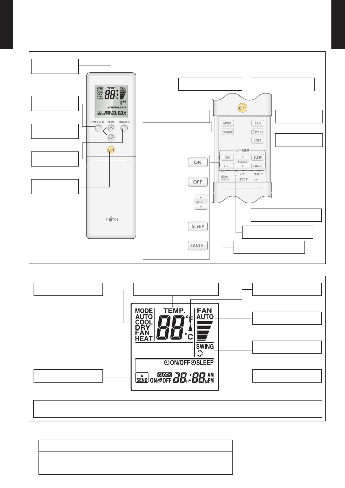
Signal
transmitter
MIN. HEAT
button
TEMP.
button
POWERFUL
button
Start/Stop
button
ECONOMY button
TIMER ON button
TIMER OFF button
TIMER SELECT button
TIMER SLEEP button
TIMER CANCEL button
MODE button
CLOCK ADJUST button
FAN button
SWING button
SET button
RESET button
°C / °F switching button
Display panel
Mode indicator
Temperature indicator
Send indicator
To facilitate explanation, the accompanying illustration has been drawn to show all possible indicators; in actual operation,
however, the display will only show those indicators appropriate to the current operation.
SPECIFICATION
Transmit indicator
Fan Speed indicator
Swing indicator
Clock & Timer
indicator
DIMENSIONS [H × W × D]: in. (mm) 8-1/16 (205) × 2-3/8 (61) × 11/16 (17)
WEIGHT oz. (g) 4.3 (122)
ACCESSORY Holder
- (01 - 21) -
NOTE: Some button operations may
not be available for all units
or systems.
For details, refer to the
operation manual.
Page 26
MULTI TYPE
8-1/16 (205)
11/16
(17)
2-3/8
(61)
Ø1/8 (Ø3.5)
1-15/16 (48.5)
4-3/16 (106.8)
5-7/8 (150)
1/8 (3.5)
1/4 (6.5)
2-3/4 (69.3)
1-1/16 (26.2)
3/16 (5.5)
2, 3, 4 ROOMS TYPE
SYSTEM DIAGRAM
MULTI TYPE
2, 3, 4 ROOMS TYPE
Control signal might not be recognized in following cases: ●
(i) A curtain or a wall, etc. exists between transmitter and receiver.
Signal transmitter
Signal receiver
window
(ii) There is an instant-start type (inverter type, etc.) uorescent lamp
in the room.
Air conditioner might not work correctly when strong light hits the ●
signal receiver window. Shut off the direct sunlight and also make
illuminator far away from the receiver window.
DIMENSIONS
Controller
z
[Unit: in.(mm)]
Top View
Holder
z
Front View Front View
Side View
Front View Side View Bottom View
- (01 - 22) -
Page 27
MULTI TYPE
2, 3, 4 ROOMS TYPE
PACKING LIST
Name and shape Quantity Application
MULTI TYPE
2, 3, 4 ROOMS TYPE
Remote controller holder 1
Tapping screw 2
Battery
[ 1.5V (LR03 / AAA) ]
SPECIFICATIONS
Dimensions [H x W x D]: in.(mm) 8-1/16 (205) × 2-3/8 (61) × 11/16 (17)
Weight: oz.(g) 4.3 (122) [w/o batteries]
2 For remote controller
Use as remote controller holder
For remote controller holder installation
- (01 - 23) -
Page 28
WIRED REMOTE CONTROLLER 2-2.
76°F (24°C)
0 3 6 9 12 15 18 21
O'clock
12 3 6 9 12 3 6 9
time
AM PM
84°F (28°C)
0 3 6 9 12 15 18 21
O'clock
12 3 6 9 12 3 6 9
time
AM PM
76°F 84°F 76°F
0 3 6 9 12 15 18 21
O'clock
12 3 6 9 12 3 6 9
time
AM PM
76°F (24°C)
84°F (28°C)
24°C 28°C 24°C
MULTI TYPE
2, 3, 4 ROOMS TYPE
(For Compact cassette type, Slim duct type)
MULTI TYPE
2, 3, 4 ROOMS TYPE
FEATURES
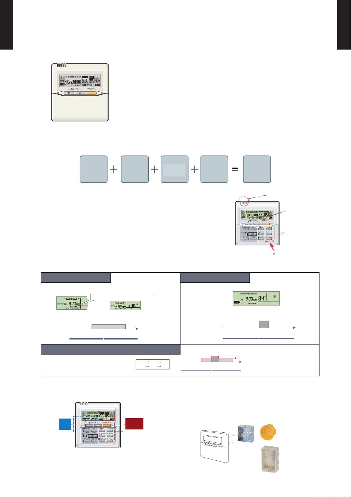
Various timer setup (ON/OFF/WEEKLY) are possible. ●
Equipped with weekly timer as standard function. ●
(Start/Stop function is twice per day for a week)
When setting up a timer, start/stop and a temperature setup can ●
be changed.
When a failure occurs,the error code is displayed. ●
Error history.(Last 16 error codes can be accessed.) ●
The room temperature can be controlled by being detective the ●
temperature accurately with Built-in thermo sensor.
Powerful features and compact size
z
Individual
control
Accurate and comfortable
z
Indoor temperature can be detected accurately by the inclusion of a
thermo sensor in the body of the wired controller.
Our system can correspond to various scenes.
This wired remote controller and the optional remote sensor allows
exibility in sensor location, and suitable for all requirements.
Thermo
sensor
Weekly
timer
Setback
timer
Wired
remote
controller
Sensor part
Thermo sensor
indicator
Control part for
changing the
thermo sensor
Built-in timers
z
Weekly timer Setback timer
Possible to set ON/OFF time to operate twice each day of the
week.
Example : setup sc reen
(Set to Wedne sday: 8:0 0 to 20:00.)
Easy-to-understa nd time ba r display
Screen
after setup
Possible to set temperature for two time spans and for each
day of the week.
At "Weekly timer" + "Set back timer" setup
Easy-to-understand operation
z
Timer
area
Operation
area
Simple installation
z
Components are compatible with standard switch
boxes. Flat back surface allows equipment to be
installed wherever it is needed.
Example : setup sc reen
(Set from S unday to Sat urday: 12:0 0 to 15:00, 28 °C .)
[Variable timer control]
The operation/display sections are zoned according
to time and operation, enabling variable programming
to match application.
- (01 - 24) -
European
switch b ox
JIS box
Page 29
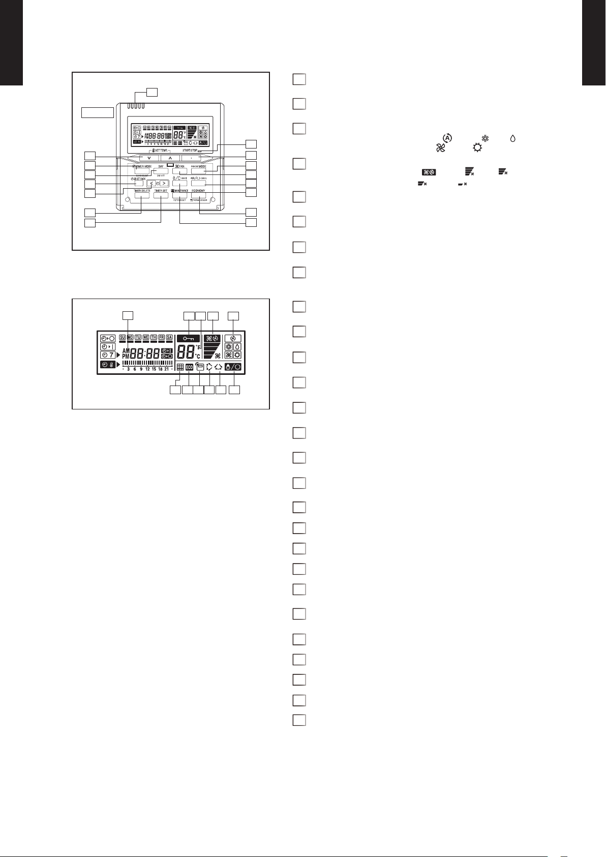
FUNCTIONS
7
Display
13
12
11
10
2
8
9
16
15
14
1
3
5
4
6
18
17
1920 21
2223 242527 26
MULTI TYPE
2, 3, 4 ROOMS TYPE
START/STOP button1
Pressed to start and stop operation.
MULTI TYPE
2, 3, 4 ROOMS TYPE
SET TEMP. button2
Selects the setting temperature.
MODE button3
Selects the operating mode ( AUTO , COOL , DRY ,
FAN , HEAT ).
FAN button4
Selects the fan speed ( AUTO , HIGH
LOW , QUIET ).
,
MED ,
Vertical air ow direction and swing button5
Press for two seconds to change the swing mode
Horizontal air ow direction and swing button6
Press for two seconds to change the swing mode.
Built-in thermo sensor7
Detect room temperature.
TIMER MODE (CLOCK ADJUST) button8
Display panel
Selects the timer mode (OFF TIMER, ON TIMER, WEEKLY TIMER)
Set the current time.
DAY (DAY OFF) button9
Temporarily cancels of one day timer.
SET BACK button10
Pressed select the set back timer.
SET TIME button11
Pressed to select the set back timer.
TIMER DELETE button12
The schedule of a weekly timer is deleted.
TIME SET button13
Sets the date, hour, minute and on-off time.
ECONOMY (THERMO SENSOR) button14
FILTER RESET button15
Operation lamp16
Lights during operation and when the timer is on.
Timer and clock indicator17
Operation mode indicator18
Fan speed indicator19
Operation lock indicator20
Temperature indicator21
Displayed temperature is set temperature.
Defrost indicator22
Indicates during the oil recovery and defrosting operation.
Vertical swing indicator 23
Horizontal swing indicator 24
Economy indicator25
Thermo sensor indicator 26
Filter indicator27
Note: Functions will be different due to type of indoor unit.
For details, please see operation manual.
- (01 - 25) -
Page 30
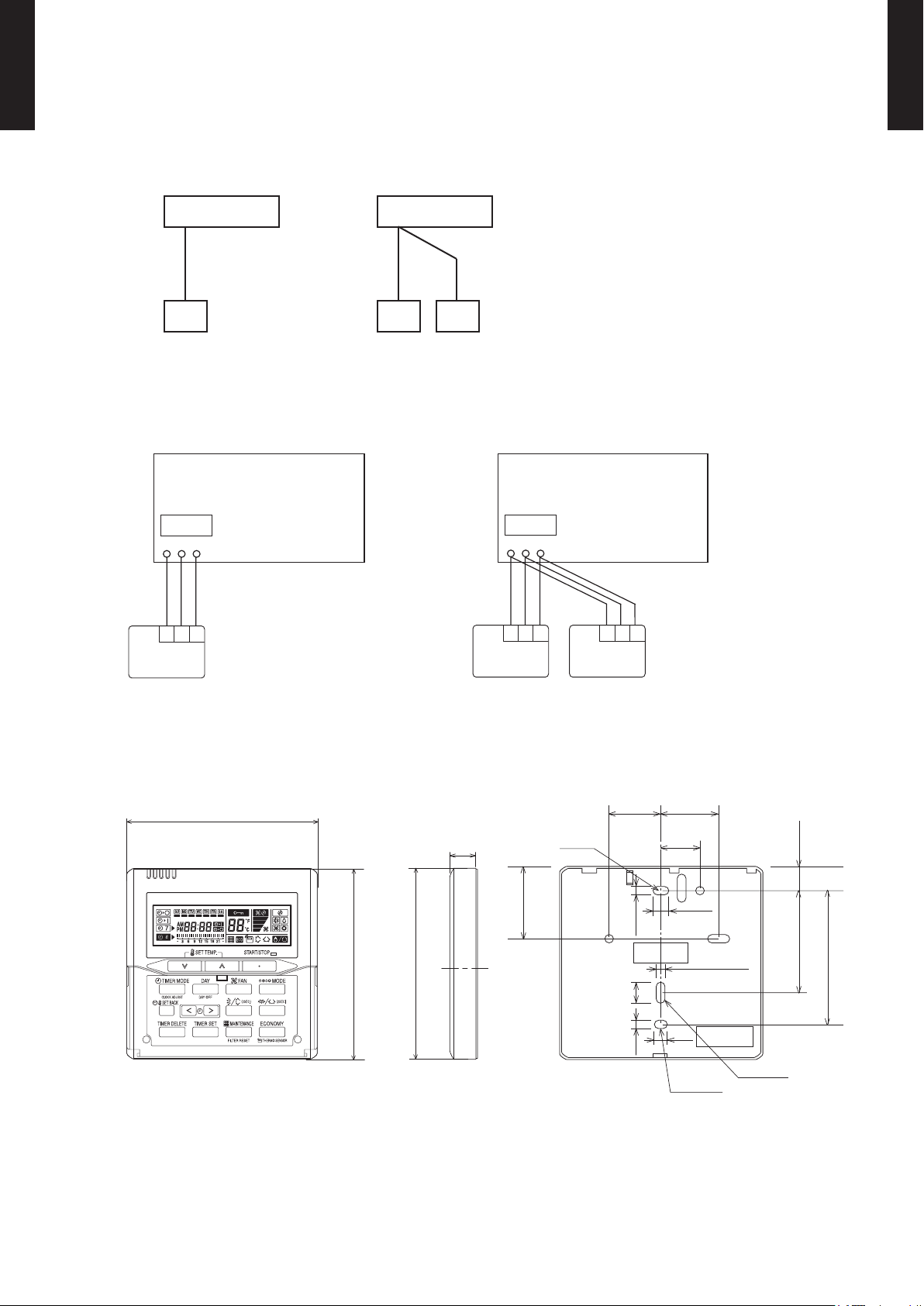
MULTI TYPE
Primary
Secondary
A B C
Indoor unit
REMOTE
CONTROLLER
1 2 3
1 2 3
Primary
Secondary
Indoor unit
1 2 3
1 2 3 1 2 3
REMOTE
CONTROLLER
3-5/16 (83.5)
5/8 (15.3)
2-1/2 (63.5)
Hole
1-13/16 (45.3)
3/16 (4.5)3/16 (4.5)
3/16 (4.5)
3/8 (9)
1/2 (12.5)
Hole x 2
Hole x 3
1/4 (6)
1-3/16 (30) 1-5/16 (33.5)
7/8 (23)
4- 3/4 (120)
4- 3/4 (120)
4- 3/4 (120)
11/16 (18)
2, 3, 4 ROOMS TYPE
SYSTEM DIAGRAM
MULTI TYPE
2, 3, 4 ROOMS TYPE
1 remote controller
z
Indoor unit Indoor unit
Remote controller Remote controllers
ELECTRICAL WIRING
1 remote controller
z
z
2 remote controllers
A , B , C : Remote controller cable.
A
z
2 remote controllers
<
1,640ft (500m) ; B+C
=
<
1,640ft (500m)
=
Remote controller Remote controllers
DIMENSIONS
Front View Side View Rear View
1 (RED) : 12V
2 (WHITE) : Signal
3 (BLACK) : COM
Unit : in. (mm)
- (01 - 26) -
Page 31

INSTALLATION
PCB
13/16 in.
(20 mm)
Connection Pattern
MULTI TYPE
2, 3, 4 ROOMS TYPE
z
MULTI TYPE
2, 3, 4 ROOMS TYPE
Note: Connection pattern is different according to type of Indoor unit.
Indoor unit types Connection Pattern
Compact Cassette type
Slim Duct type
Pattern A
ASU7RLF1, ASU9RLF1, ASU12RLF1
Wall Mounted type
Pattern A
z
ASU9RLS2, ASU12RLS2, ASU15RLS2
ASU18RLF, ASU24RLF
Floor type
Pattern BASU7RLF, ASU9RLF, ASU12RLF
Pattern C
Connect the end of remote controller cable directly to the exclusive terminal block.
M4 screw
Terminal block
Remote
controller
cable
Remote controller
terminal block
Indoor unit
Outdoor unit /
Power supply
terminal block
Note: It may be failed if it is connected to the outdoor unit or the terminal block for power supply.
Pattern B
z
1) Modify the remote controller cable as per below methods.
Use a tool to cut off the terminal on the end of the remote controller cable and then remove ●
the insulation from the cut end of the cable as shown in Fig.
Connect the remote controller cable and connecting cable as shown in Fig. ●
Be sure to insulate the connection between the cables. ●
Connecting
cable
White
Remote controller
cable
Red
White
Red
Black
Black
Insulated
connection
2) Method of connecting remote controller cable
Connecting cable made by above-mentioned 1) is connected with terminal (*1) of optional ●
communication kit.
Cable connected with terminal (*2) of communication kit is connected with PCB of Indoor unit. ●
*1: CN305 (for ASU7RLF, ASU9RLF, ASU12RLF: UTY-XCBXZ1)
CNC01 (for ASU9RLS2, ASU12RLS2, ASU15RLS2: UTY-TWBXF)
CNC01 (for ASU7RLF1, ASU9RLF1, ASU12RLF1: UTY-XCBXZ2)
*2: CN301 (for ASU7RLF, ASU9RLF, ASU12RLF: UTY-XCBXZ1)
CND01 (for ASU9RLS2, ASU12RLS2, ASU15RLS2: UTY-TWBXF)
CND01 (for ASU7RLF1, ASU9RLF1, ASU12RLF1: UTY-XCBXZ2)
Remote controller
cable
Connecting
cable
Terminal
(*2)
Terminal
(*1)
Communication kit Indoor unit PCB
- (01 - 27) -
Page 32

Pattern C
13/16 in.
(20 mm)
MULTI TYPE
2, 3, 4 ROOMS TYPE
z
MULTI TYPE
2, 3, 4 ROOMS TYPE
1) Modify the remote controller cable as per below methods.
Use a tool to cut off the terminal on the end of the remote controller cable and then remove ●
the insulation from the cut end of the cable as shown in Fig.
Connect the remote controller cable and connecting cable as shown in Fig. ●
Be sure to insulate the connection between the cables. ●
Connecting
cable
White
Red
Black
Insulated
connection
Remote controller
cable
White
Red
Black
2) Method of connecting remote controller cable
Connecting cable made by above-mentioned 1) is connected with PCB of Indoor unit. ●
Remote controller
cable
Connecting
cable
Indoor unit PCB
- (01 - 28) -
Page 33

MULTI TYPE
2, 3, 4 ROOMS TYPE
PACKING LIST
Name and shape Quantity Application
MULTI TYPE
2, 3, 4 ROOMS TYPE
Remote controller cable
[33ft(10m)]
Screw
(M4 x 16mm)
Binder 1
Connecting cable
Screw *1
(M4 x 14mm)
Cable clamper *1
Installation manual
Operating manual
Use only if the remote controller cable must be modied for the indoor unit model.
*1:
*1 1
For connecting the remote controller
1
For installing the remote controller
2
For remote controller and remote controller cable
binding
For connecting the remote controller cable to the
Wall mounted type indoor unit
For installing the remote controller cable to the
1
indoor unit
For installing the remote controller cable to the
1
indoor unit
1
1
WIRING SPECIFICATIONS
Use Cable size Wire type Remarks
Remote controller
cable
SPECIFICATIONS
Dimensions [H x W x D]: in.(mm) 4-3/4 (120) x 4-3/4 (120) x 11/16 (18)
Weight: oz. (g) 5.6 (160)
PART (OPTIONAL)
Model name
22AWG
( 0.33 mm2 )
ASU7RLF
ASU9RLF
ASU12R LF
UT Y-XCBXZ1 UT Y-T WBX F UT Y-XC BX Z 2
Polar 3 core Use sheathed PVC cable
Wall mounted type
ASU9RLS2
ASU12RLS2
ASU15RLS2
ASU7RLF1
ASU9RLF1
ASU12 RLF1
* The communication kit is needed for connecting the wired remote controller to the Wall mounted type.
- (01 - 29) -
Page 34

SPECIFICATIONS3.
COMPACT CASSETTE TYPE3-1.
MULTI TYPE
2, 3, 4 ROOMS TYPE
Model name AUU7RLF AUU9RLF AUU12RL F AUU18RLF
Power source 1ø 208/230V 60Hz
Available voltage range 187-26 4V
Capacity 7,000 Btu/h class 9,000 Btu/h class 12,000 Btu/h class 18,000 Btu/h class
Input power W 18 18 23 39
Running current A 0 .15 0.15 0.19 0.30
High
Cooling
Airow
Fan
Sound pressure level *
Heat
exchanger
Dimensions
(H × W × D)
Weight
Connection
pipe
Operation range
Drain hose
Cassette
grille
Remote controller type Wired [Wireless(option)]
NOTE :
• The protective function might work when using it outside the operation range.
*: These are the measured values in the manufacturer’s anechoic chamber.
Because of the surrounding sound environment, the sound levels measured in actual installation conditions might be higher than the
specied values here.
rate
Heating
Fan Type × Q'ty Turbo × 1
Fan Motor Output W 54
Cooling
Heating
Dimension (H × W × D) in. (mm)
Fin pitch FPI 21
Rows × Stages 2 × 10
Pipe type Copper tube
Fin Type Aluminum
Net
Gross 10-7/16 × 28-3/4 × 24-5/8 (265 × 730 × 625)
Net
Gross 40 (18)
Size
Method Flare
Material HARD PVC
size in. [mm] Ø 1(I.D.), Ø 1-1/4(O.D.) [Ø 25 (I.D.), Ø 32 (O.D.)]
Model name UTG-CCGF
Material PS
Color
Dimensions
(H × W × D)
Weight
Liquid
Gas Ø3/8 (Ø9.52) Ø1/2 (Ø12.70)
Cooling
Heating °F (°C) 60 to 88 (16 to 31)
Med 288 (490) 288 (490) 312 (530) 359 (610)
Low 259 (440) 259 (440) 277 (470) 306 (520)
Quiet 230 (390) 230 (390) 241 (410) 241 (410)
High 318 (540) 318 (540) 359 (610) 471 (800)
Med 288 (490) 288 (490) 312 (530) 418 (710)
Low 259 (440) 259 (440) 277 (470) 353 (600)
Quiet 230 (390) 230 (390) 241 (410) 265 (450)
High
Med 31 31 33 37
Low 29 29 31 33
Quiet 27 27 28 29
High 34 34 37 44
Med 32 32 33 40
Low 29 29 31 37
Quiet 27 27 28 30
Net
Gross 4-3/4 × 30-1/8 × 29-3/4 (120 × 765 × 755)
Net
Gross 10 (4.5)
CFM
(m3/h)
dB (A)
in. (mm)
lbs. (kg)
in. (mm)
°F (°C) 64 to 90 (18 to 32)
%RH 80 or less
in. (mm)
lbs. (kg)
318 (540) 318 (540) 359 (610) 441 (750)
33 33 37 42
8-1/4 × 51-9/16 × 1/2 + 8-1/4 × 49-3/16 × 1/2
(210 × 1310 × 13.3 + 210 × 1250 × 13.3)
9-5/8 × 22-7/16 × 22-7/16 (245 × 570 × 570)
33 (15)
Ø1/4 (Ø6.35)
WHITE
(Approximate colour of MUNSELL N 9.25 /)
1-15/16 × 27-9/16 × 27-9/16 (49 × 700 × 700)
5.7 (2.6)
MULTI TYPE
2, 3, 4 ROOMS TYPE
- (01 - 30) -
Page 35

SLIM DUCT TYPE3-2.
MULTI TYPE
2, 3, 4 ROOMS TYPE
Model name ARU7RLF ARU9RLF ARU12RLF ARU18RLF ARU24RLF
Power source 1ø 208/230V 60Hz
Available voltage range 187-26 4V
Capacity
Input power W 33 49 58 73 111
Running current A 0.30 0.30 0.35 0.44 0.66
High
Cooling
Airow
Fan
Recommended static pressure in.WG (Pa)
Sound pressure level *
Heat
exchanger
Enclosure
Dimensions
(H × W ×D)
Weight
Connection
pipe
Drain hose
Operation range
Remote controller type Wired [Wireless(option)]
NOTE :
• Specications are based on the following conditions.
Standard static pressure : 0.10in.WG (25Pa)
• The protective function might work when using it outside the operation range.
*: These are the measured values in the manufacturer’s anechoic chamber.
Because of the surrounding sound environment, the sound levels measured in actual installation conditions might be higher than the
specied values here.
rate
Heating
Fan type × Q'ty Sirocco × 2 Sirocco × 3 Sirocco × 4
Fan motor output W 80 81 81 81 81
Cooling
Heating
Dimension (H × W × D) in. (mm)
Fin pitch FPI 20
Rows × Stages 2 × 14 3 × 14
Pipe type Copper tube
Fin Type Aluminum
Material GALVANIZED STEEL SHEET
Color -
Net
Gross
Net
Gross 49 (22) 51 (23) 60 (27) 68 (31)
Size
Method Flare
Material HARD PVC
size in. [mm] Ø 1(I.D.), Ø 1-1/4(O.D.) [Ø 25(I.D.), Ø 32(O.D.)]
Liquid
Gas Ø3/8 (Ø9.52) Ø1/2 (Ø12.70) Ø5/8 (Ø15.88)
Cooling
Heating °F (°C) 60 to 88 (16 to 31)
Med 288 (490) 324 (550) 353 (600) 518 (880) 730 (1,240)
Low 277 (470) 294 (500) 324 (550) 483 (820) 648 (1,100)
Quiet 259 (440) 265 (450) 283 (480) 442 (750) 607 (1,030)
High 324 (550) 353 (600) 383 (650) 554 (940) 783 (1,330)
Med 288 (490) 324 (550) 353 (600) 518 (880) 730 (1,240)
Low 277 (470) 294 (500) 324 (550) 483 (820) 648 (1,100)
Quiet 259 (440) 265 (450) 283 (480) 442 (750) 607 (1,030)
High
Med 26 27 28 31 32
Low 25 26 27 30 30
Quiet 24 25 26 29 29
High 28 28 29 33 35
Med 26 26 28 32 34
Low 25 25 27 31 32
Quiet 24 24 24 29 29
CFM
(m3/h)
dB(A)
in. (mm)
lbs. (kg)
in. (mm)
°F (°C) 64 to 90 (18 to 32)
%RH 80 or less
7,000 Btu/h
class
324 (550) 353 (600) 383 (650) 554 (940) 783 (1,330)
0 to 0.36
(0 to 90)
28 28 29 32 33
11-9/16 × 19-
11/16 × 1-1/16
(294 × 500 ×
26.6)
37 (17) 40 (18) 49 (22) 55 (25)
9,000 Btu/h
class
0 to 0.36
(0 to 90)
11-9/16 × 19-11/16 × 1-9/16
(294 × 500 × 39.9)
7-13/16 x 27-9/16 x 24-7/16
(198 × 700 × 620)
10-13/16 x 37-3/16 x 30-3/8
(274 × 945 × 772)
12,000 Btu/h
Ø1/4 (Ø6.35)
class
0 to 0.36
(0 to 90)
18,000 Btu/h
class
0 to 0.36
(0 to 90)
11-9/16 × 279/16 × 1-9/16
(294 × 700 ×
39.9)
7-13/16 x 35-
7/16 x 24-7/16
(198 × 900 ×
620)
10-13/16 x 45-
1/16 x 30-3/8
(274 × 1,145 ×
772)
24,000 Btu/h
class
0 to 0.20
(0 to 50)
11-9/16 × 357/16 × 1-9/16
(294 × 900 ×
39.9)
7-13/16 x 435/16 x 24-7/16
(198 × 1,100 ×
620)
10-13/16 x 52-
15/16 x 30-3/8
(274 × 1,345 ×
772)
MULTI TYPE
2, 3, 4 ROOMS TYPE
- (01 - 31) -
Page 36

WALL MOUNTED TYPE3-3.
MULTI TYPE
2, 3, 4 ROOMS TYPE
Model name A SU7RLF1 A SU9 RLF1 ASU12RLF1
Power source 1ø 208/230V 60Hz
Available voltage range 187-264V
Capacity 7,000 Btu/h class 9,000 Btu/h class 12,000 Btu/h class
Input power W 15 17 22
Running current A 0 .13 0 .15 0 .19
High
Cooling
Airow
Fan
Sound pressure level *
Heat
exchanger
Enclosure
Dimensions
(H × W ×D)
Weight
Connection
pipe
Drain hose
Operation range
Remote controller type Wireless [Wired(option)]
NOTE :
• The protective function might work when using it outside the operation range.
*: These are the measured values in the manufacturer’s anechoic chamber.
Because of the surrounding sound environment, the sound levels measured in actual installation conditions might be higher than the
specied values here.
rate
Heating
Fan type × Q'ty Cross ow × 1
Fan motor output W 30 30 30
Cooling
Heating
Dimension (H × W × D) in.(mm)
Fin pitch FPI Main: 23, Sub: 18
Rows × Stages Main: 2 x 20, Sub: 1 x 4
Pipe type Copper tube
Fin Type Aluminum
Material Polystyrene
Color
Net
Gross 10-5/8 × 34-13/16 × 14-3/4 (270 × 884 × 336)
Net
Gross 23 (10.5)
Size
Method Flare
Material PP + LLDPE
size in. [mm]
Liquid
Gas Ø3/8 (Ø9.52)
Cooling
Heating °F (°C) 60 to 86 (16 to 30)
Med 294 (500) 306 (520) 330 (560)
Low 253 (430) 253 (430) 265 (450)
Quiet 182 (310) 182 (310) 182 (310)
High 330 (560) 353 (600) 388 (660)
Med 294 (500) 306 (520) 330 (560)
Low 253 (430) 253 (430) 277 (470)
Quiet 194 (330) 194 (330) 194 (330)
High
Med 32 33 36
Low 29 29 30
Quiet 21 21 21
High 36 37 40
Med 32 33 36
Low 29 29 31
Quiet 22 22 22
CFM
(m3/h)
dB(A)
in. (mm)
lbs. (kg)
in.(mm)
°F (°C) 64 to 90 (18 to 32)
%RH 80 or less
330 (560) 353 (600) 388 (660)
36 37 40
Main: 12-5/8 x 24-13/16 x 13/16 (320 x 630 x 20)
Sub: 3-5/16 x 24-13/16 x 1/2 (84 x 630 x 13.3)
WHITE
(Approximate color of MUNSELL N9.25 /)
10-9/16 × 33-1/16 × 8 (268 × 840 × 203)
19 (8.5)
Ø1/4 (Ø6.35)
Ø 9/16(I.D.), Ø 5/8 to Ø 11/16(O.D.)
[Ø 13.8(I.D.), Ø 15.8 to Ø 16.7(O.D.)]
MULTI TYPE
2, 3, 4 ROOMS TYPE
- (01 - 32) -
Page 37

MULTI TYPE
2, 3, 4 ROOMS TYPE
Model name ASU7RLF ASU9RLF ASU12 RLF
Power source 1ø 208/230V 60Hz
Available voltage range 187-264V
Capacity 7,000 Btu/h class 9,000 Btu/h class 12,000 Btu/h class
Input power W 15 17 22
Running current A 0.1 3 0.15 0.1 9
High
Cooling
Airow
Fan
Sound pressure level *
Heat
exchanger
Enclosure
Dimensions
(H × W ×D)
Weight
Connection
pipe
Drain hose
Operation range
Remote controller type Wireless [Wired(option)]
NOTE :
• The protective function might work when using it outside the operation range.
*: These are the measured values in the manufacturer’s anechoic chamber.
Because of the surrounding sound environment, the sound levels measured in actual installation conditions might be higher than the
specied values here.
rate
Heating
Fan type × Q'ty Cross ow × 1
Fan motor output W 30 30 30
Cooling
Heating
Dimension (H × W × D) in.(mm)
Fin pitch FPI Main: 23, Sub: 18
Rows × Stages Main: 2 x 20, Sub: 1 x 4
Pipe type Copper tube
Fin Type Aluminum
Material Polystyrene
Color
Net
Gross 10-3/8 × 33-1/16 × 14-3/4 (263 × 840 × 375)
Net
Gross 23 (10.5)
Size
Method Flare
Material PP + LLDPE
size in. [mm]
Liquid
Gas Ø3/8 (Ø9.52)
Cooling
Heating °F (°C) 60 to 88 (16 to 31)
Med 294 (500) 306 (520) 330 (560)
Low 253 (430) 253 (430) 265 (450)
Quiet 200 (340) 200 (340) 200 (340)
High 330 (560) 353 (600) 388 (660)
Med 294 (500) 306 (520) 330 (560)
Low 253 (430) 253 (430) 277 (470)
Quiet 206 (350) 206 (350) 206 (350)
High
Med 32 33 36
Low 29 29 30
Quiet 25 25 25
High 36 37 40
Med 32 33 36
Low 29 29 31
Quiet 25 25 25
CFM
(m3/h)
dB(A)
in. (mm)
lbs. (kg)
in.(mm)
°F (°C) 64 to 90 (18 to 32)
%RH 80 or less
330 (560) 353 (600) 388 (660)
36 37 40
Main: 12-5/8 x 24-13/16 x 13/16 (320 x 630 x 20)
Sub: 3-5/16 x 24-13/16 x 1/2 (84 x 630 x 13.3)
WHITE
(Approximate color of MUNSELL N9.25 /)
11-1/16 × 31-1/16 × 8 (280 × 790 × 203)
18 (8)
Ø1/4 (Ø6.35)
Ø 9/16(I.D.), Ø 5/8 to Ø 11/16(O.D.)
[Ø 13.8(I.D.), Ø 15.8 to Ø 16.7(O.D.)]
MULTI TYPE
2, 3, 4 ROOMS TYPE
- (01 - 33) -
Page 38

MULTI TYPE
2, 3, 4 ROOMS TYPE
Model name ASU9RLS2 ASU12RLS2 ASU15RLS2
Power source 208/230V~ 60Hz
Available voltage range 187-26 4V
Capacity 9,000 Btu/h class 12,000 Btu/h class 14,000 Btu/h class
Input power W 16 19 23
Running current A 0 .14 0 .17 0.20
High
Cooling
Airow
Fan
Sound pressure level *
Heat
exchanger
Enclosure
Dimensions
(H × W × D)
Weight
Connection
pipe
Drain hose
Operation range
Remote controller type Wireless [Wired(option)]
NOTE :
• The protective function might work when using it outside the operation range.
*: These are the measured values in the manufacturer’s anechoic chamber.
Because of the surrounding sound environment, the sound levels measured in actual installation conditions might be higher than the
specied values here.
rate
Heating
Fan type × Q'ty Cross ow ×1
Fan motor output W 36
Cooling
Heating
Dimension (H × W × D) in. (mm)
Fin pitch FPI Main: 23, Sub: 18
Rows × Stages Main: 2 x 20, Sub: 1 x 4
Pipe type Copper tube
Fin Type Aluminum
Material Polystyrene
Color
Net
Gross 9-3/4 × 36-1/4 × 14-11/16 (247 x 920 x 373)
Net
Gross 27(12)
Size
Method Flare
Material PP + LLDPE
size in. [mm]
Liquid
Gas Ø 3/8(Ø 9.52) Ø 1/2(Ø 12.70)
Cooling
Heating °F (°C) 60 to 88 (16 to 31)
Med 324 (550) 353 (600) 377 (640)
Low 277 (470) 312 (530) 336 (570)
Quiet 194 (330) 194 (330) 230 (390)
High 353 (600) 388 (660) 418 (710)
Med 324 (550) 353 (600) 377 (640)
Low 277 (470) 312 (530) 347 (590)
Quiet 194 (330) 194 (330) 253 (430)
High
Med 32 34 36
Low 28 31 33
Quiet 21 21 25
High 36 37 41
Med 32 34 36
Low 28 31 34
Quiet 21 21 27
CFM
(m3/h)
dB(A)
in.(mm)
lbs. (kg)
in. (mm)
°F (°C) 64 to 90 (18 to 32)
%RH 80 or less
353 (600) 388 (660) 418 (710)
36 37 41
Main: 12-5/8 × 27-3/16 × 13/16 (320 × 690 × 20)
Sub: 3-5/16 × 27-3/16 × 1/2 (84 × 690 × 13.3)
WHITE
(Approximate colour of MUNSELL N9.3/)
11-1/8 × 34-1/4 × 7-5/16 (282 x 870 x 185)
21(9.5)
Ø 1/4(Ø 6.35)
Ø 9/16(I.D.), Ø 5/8 to Ø11/16(O.D.)
[Ø 13.8(I.D.), Ø 15.8 to Ø 16.7(O.D.)]
MULTI TYPE
2, 3, 4 ROOMS TYPE
- (01 - 34) -
Page 39

MULTI TYPE
2, 3, 4 ROOMS TYPE
Model name ASU18 RLF ASU24RLF
Power source 1ø 208/230V 60Hz
Available voltage range 187-264V
Capacity 18,000 Btu/h class 24,000 Btu/h class
Input power W 41 69
Running current A 0.32 0.53
High
Cooling
Airow
Fan
Sound pressure level *
Heat
exchanger
Enclosure
Dimensions
(H × W × D)
Weight
Connection
pipe
Drain hose
Operation range
Remote controller type Wireless [Wired(option)]
NOTE :
• The protective function might work when using it outside the operation range.
*: These are the measured values in the manufacturer’s anechoic chamber.
Because of the surrounding sound environment, the sound levels measured in actual installation conditions might be higher than the
specied values here.
rate
Heating
Fan type × Q'ty Cross ow ×1
Fan motor output W 42 42
Cooling
Heating
Dimension (H × W × D) in. (mm)
Fin pitch FPI Main: 21, Sub: 18
Rows × Stages Main: 2 x 18, Sub: 1 x 4
Pipe type Copper tube
Fin Type Aluminum
Material Polystyrene
Color
Net
Gross 12-9/16 x 42-15/16 x 16-7/8 (319 × 1,090 × 429)
Net
Gross 40 (18) 40 (18)
Size
Method Flare
Material PVC
size in. [mm] Ø 1/2(I.D.), Ø 5/8(O.D.) [Ø 12(I.D.), Ø 16(O.D.)]
Liquid
Gas Ø1/2 (Ø12.70) Ø5/8 (Ø15.88)
Cooling
Heating °F (°C) 60 to 88 (16 to 31)
Med 436 (740) 530 (900)
Low 365 (620) 436 (740)
Quiet 324 (550) 365 (620)
High 542 (920) 647 (1,100)
Med 436 (740) 530 (900)
Low 365 (620) 436 (740)
Quiet 324 (550) 365 (620)
High
Med 37 42
Low 33 37
Quiet 31 33
High 44 48
Med 37 42
Low 33 37
Quiet 31 33
CFM
(m3/h)
dB(A)
mm
lbs. (kg)
in. (mm)
°F (°C) 64 to 90 (18 to 32)
%RH 80 or less
542 (920) 659 (1,120)
43 49
Main:15-7/8 x 33-3/4 x 1-1/16 (378 x 832 x 26.6)
Sub:3-5/16 x 33-3/4 x 1/2 (84 x 832 x 13.3)
WHITE
(Approximate color of MUNSELL N9.25 /)
12-5/8 x 39-1/4 x 9 (320 × 998 × 228)
31 (14) 31 (14)
Ø1/4 (Ø6.35)
MULTI TYPE
2, 3, 4 ROOMS TYPE
- (01 - 35) -
Page 40

FLOOR TYPE3-4.
MULTI TYPE
2, 3, 4 ROOMS TYPE
Model name AGU9RLF AGU12RLF AGU15RLF
Power source 1ø 208/230V 60Hz
Available voltage range 18 7-2 6 4V
Capacity 9,000 Btu/h class 12,000 Btu/h class 14,000 Btu/h class
Input power W 16 20 23
Running current A 0.15 0 .18 0.20
High
Cooling
Airow
Fan
Sound pressure level *
Heat
exchanger
Enclosure
Dimensions
(H × W × D)
Weight
Connection
pipe
Drain hose
Operation range
Remote controller type Wireless [Wired (option)]
NOTE :
• The protective function might work when using it outside the operation range.
*: These are the measured values in the manufacturer’s anechoic chamber.
Because of the surrounding sound environment, the sound levels measured in actual installation conditions might be higher than the
specied values here.
rate
Heating
Type × Q'ty Crossow x 2
Motor output W 16
Cooling
Heating
Dimension (H × W × D) in. (mm) 14-7/8 x 21-5/8 x 1-1/16 (378 × 550 × 26.6)
Fin pitch FPI 21
Rows × Stages 2 x 18
Pipe type Copper tube
Fin Type Aluminium
Material Polystyrene
Colour
Net
Gross 27-9/16 x 32-5/16 x 12-3/16 (700 × 820 × 310)
Net
Gross 37 (17)
Size
Method Flare
Material PVC
size in. (mm) Ø 9/16(I.D.), Ø 11/16(O.D.) [Ø 13.8 (I.D.), Ø 16.7 (O.D.)]
Liquid
Gas Ø3/8in. (Ø 9.52) Ø1/2in. (Ø 12.70)
Cooling
Heating °F (°C) 60 to 86 (16 to 30)
Med 259 (440) 288 (490) 306 (520)
Low 212 (360) 224 (380) 235 (400)
Quiet 159 (270) 159 (270) 159 (270)
High 312 (530) 353 (600) 383 (650)
Med 270 (460) 300 (510) 318 (540)
Low 224 (380) 241 (410) 253 (430)
Quiet 159 (270) 159 (270) 159 (270)
High
Med 34 36 38
Low 28 30 31
Quiet 22 22 22
High 39 42 44
Med 35 38 39
Low 30 32 33
Quiet 22 22 22
CFM
(m3/h)
dB(A)
in. (mm)
Ibs. (kg)
in. (mm)
°F (°C) 64 to 90 (18 to 32)
%RH 80 or less
312 (530) 353 (600) 383 (650)
39 42 44
WHITE
(Approximate colour of MUNSELL N9.25/)
23-5/8 x 29-1/8 x 7-7/8 (600 × 740 × 200)
31 (14)
Ø1/4in. (Ø 6.35)
MULTI TYPE
2, 3, 4 ROOMS TYPE
- (01 - 36) -
Page 41

DIMENSIONS4.
(Drain hose)
20-7/8 (530): Hanging bolt position
4 (102)
5-5/16
(135)
9-13/16 (250)
27-9/16 (700)
27-9/16 (700)
2-15/16 (75)
1-3/16 (30)
1-3/16 (30)
10-5/16 (262)
21-1/4 (540): Hanging bolt position
□ 22-7/16 (570): Indoor unit
□ 22-13/16 to 26 (580 to 660)
: Ceiling openings
•
Cassette grille mounting state
Top view
5-14/16 to 7-7/8 (150 to 200)
Min. 17-11/16 (450)
Min. 17-11/16 (450)
Maintenance space
Side view
8-7/16 (215)
4-13/16 (123)
2-5/16 (58)
4-1/2 (114)
5-3/4 (146)
4-1/4
(108)
4 (102)
9-5/8 (245)
1-3/16 (30)
1-9/16 (40)
3-7/8 (99)
Drain port
Control box
Ceiling
Drain port
Be sure to leave
maintenance space
for future service
at the designated
position.
Bottom view
1-3/16 (30)
1-15/16 (49)
Side view
COMPACT CASSETTE TYPE4-1.
MULTI TYPE
2, 3, 4 ROOMS TYPE
MODELS : AUU7RLF, AUU9RLF, AUU12RLF, AUU18RLF
Unit: in. (mm)
MULTI TYPE
2, 3, 4 ROOMS TYPE
AUU7RLF, AUU9RLF,
AUU12RLF
Refrigerant pipe are
connection
Drain hose connection Drain hose I.D.: Ø 1 in.(Ø 25 mm), O.D.: Ø 1-1/4 in.(Ø 32 mm)
Liquid ø 1/4 in. (ø 6.35 mm) ø 1/4 in. (ø 6.35 mm)
Gas ø 3/8 in. (ø 9.52 mm) ø 1/2 in. (ø 12.70 mm)
- (01 - 37) -
AUU18RLF
Page 42

MULTI TYPE
40 (1,000)
or more
40 (1,000)
or more
95 (2,400)
or more
11 (262)
or more
Strong and durable ceiling
Obstruction
Floor
4 (100) or more
*
2, 3, 4 ROOMS TYPE
INSTALLATION PLACE
Unit : in. (mm)
MULTI TYPE
2, 3, 4 ROOMS TYPE
H
H (The maximum height from oor to ceiling)
Unit: in. (mm)
Model name AUU7 AUU9 AUU12 AUU18
Standard mode
107
(2,700)
107
(2,700)
107
(2,700)
107
(2,700)
High Ceiling mode - -
3-way directions setting
z
119
(3,000)
119
(3,000)
To set “3-way directions”, the air outlet shutter plate (UTR-YDZB) sold separately must be
installed and “outlet-direction” switched to “3-way” by remote controller.
*When installing the indoor unit, be careful about the maintenance space.
- (01 - 38) -
Page 43

SLIM DUCT TYPE4-2.
Rear view
View A
Top view
Side view
Front view
Bottom view
(Drain hose)
Drain port
2 (51)
22-5/8 (574)
6-17/8 (174)
2-13/16 (71)
6 (152)
3-15/16 (100) x 6 = 23-5/8 (600)
3-7/32 (82)
1-7/8 (48)
25-9/16 (650)
28-7/8 (734)
1-3/16 (30)
14-13/16 (377)
6-9/16 (167)
4-11/16 (119)
3-1/2 (89)
3-1/16 (78)
2-3/16 (55)
1-7/8 (47)
3/8 (10)
24-7/16 (620)
14-5/8 (371)
10-3/8 (264)
5-11/16 (144)
2-11/16 (69)
25-9/16 (650)
26-1/8 (664)
27-9/16 (700)
1-11/16 (43)
13/16 (20)
7-13/16 (198)
6-5/8 (168)
5-15/16 (151)
3-1/16 (78) 2-3/16 (55)
MULTI TYPE
2, 3, 4 ROOMS TYPE
MODELS : ARU7RLF, ARU9RLF, ARU12RLF
Unit : in. (mm)
MULTI TYPE
2, 3, 4 ROOMS TYPE
ARU7, ARU9, ARU12
Refrigerant pipe are
connection
Drain hose connection Drain hose I.D.: Ø 1 in.(Ø 25 mm), O.D.: Ø 1-1/4 in.(Ø 32 mm)
Liquid ø 1/4 in. (ø 6.35 mm)
Gas ø 3/8 in. (ø 9.52 mm)
- (01 - 39) -
Page 44

MODEL : ARU18RLF
Rear view
View A
Top view
Side view
Front view
Bottom view
(Drain hose)
Drain port
2 (51)
30-1/2 (774)
6-7/8 (174)
2-13/16 (71)
6 (152)
3-7/16 (87)
2-3/16 (56)
33-7/16 (850)
36-3/4 (934)
3-15/16 (100) x 8 = 31-1/2 (800)
1-3/16 (30)
14-13/16 (377)
6-9/16 (167)
4-11/16 (119)
3-1/2 (89)
3-1/16 (78)
2-3/16 (55)
1-7/8 (47)
3/8 (10)
24-7/16 (620)
14-5/8 (371)
10-3/8 (264)
5-11/16 (144)
2-11/16 (69)
33-7/16 (850)
34 (864)
35-7/16 (900)
1-11/16 (43)
13/16
(20)
7-13/16 (198)
6-5/8 (168)
5-15/16 (151)
3-1/16 (78)
2-3/16 (55)
Unit : in. (mm)
MULTI TYPE
2, 3, 4 ROOMS TYPE
MULTI TYPE
2, 3, 4 ROOMS TYPE
Refrigerant pipe are
connection
Drain hose connection Drain hose I.D.: Ø 1 in.(Ø 25 mm), O.D.: Ø 1-1/4 in.(Ø 32 mm)
Liquid ø 1/4 in. (ø 6.35 mm)
Gas ø 1/2 in. (ø 12.70 mm)
ARU18
- (01 - 40) -
Page 45

MODEL : ARU24RLF
Rear view
View A
Top view
Side view
Front view
Bottom view
(Drain hose)
Drain port
38-3/8 (974)
2 (51)
6-7/8 (174)
2-13/16 (71)
6 (152)
44-5/8 (1,134)
2-3/16 (56)
3-7/16 (87)
3-15/16 (100) x 10 = 39-3/8 (1,000)
41-5/16 (1,050)
1-3/16 (30)
14-13/16 (377)
6-9/16 (167)
4-11/16 (119)
3-1/2 (89)
3-1/16 (78)
2-3/16 (55)
1-7/8 (47)
6/16 (10)
24-7/16 (620)
14-5/8 (371)
10-6/16 (264)
5-11/16 (144)
2-11/16 (69)
43-5/16 (1,100)
1-11/16 (43)
13/16 (20)
7-13/16 (198)
6-5/8 (168)
5-15/16 (151)
3-1/16 (78)
2-3/16 (55)
Unit : in. (mm)
MULTI TYPE
2, 3, 4 ROOMS TYPE
MULTI TYPE
2, 3, 4 ROOMS TYPE
Refrigerant pipe are
connection
Drain hose connection Drain hose I.D.: Ø 1 in.(Ø 25 mm), O.D.: Ø 1-1/4 in.(Ø 32 mm)
Liquid ø 1/4 in. (ø 6.35 mm)
Gas ø 5/8 in. (ø 15.88 mm)
ARU24
- (01 - 41) -
Page 46

Left
side
Strong and durable ceiling
Indoor unit
Right
side
4 (100)
or more
12 (300)
or more
Service access Ceiling
99 (2,500) or more
(When no ceiling)
Floor
10 (240) or more
1 (20) or more
1 (20) or more
12 (300) or more
1 (10)
or less
1 (10)
or less
Left side
Strong and
durable floor
Right side
(PIPE side)
Grille
Inlet air
Strong and
durable floor
6
(150)
or more
4 (100)
or more
12 (300)
or more
1 (20)
or more
1 (20)
or more
6 (150)
or more
Left side
Strong and
durable floor
Right side
(PIPE side)
Duct
Grille
Inlet air
Strong and
durable floor
6
(150)
or more
4 (100)
or more
12 (300)
or more
1 (20)
or more
1 (20)
or more
6 (150)
or more
Unit : in. (mm)
MULTI TYPE
2, 3, 4 ROOMS TYPE
INSTALLATION PLACE
MULTI TYPE
2, 3, 4 ROOMS TYPE
- (01 - 42) -
Page 47

Service access
Unit
Control
box
or more
Service space
12 (300)
12 (300)
or more
4 (100)
or more
Unit : in. (mm)
MULTI TYPE
2, 3, 4 ROOMS TYPE
MAINTENANCE SPACE
Provide a service access for inspection purposes as shown below.
Do not place any wiring or illumination in the service space, as they will impede service.
MULTI TYPE
2, 3, 4 ROOMS TYPE
- (01 - 43) -
Page 48

WALL MOUNTED TYPE4-3.
33-1/16 (840) 8 (203)
10-9/16 (268)
(33-1/16(840))
1-3/4(45)
2-1/16(52)
14-5/16(364)
Ø2-9/16 (Ø65)
for pipe inlet
12-5/8(321)
3-7/16
(88)
Ø2-9/16 (Ø65)
for pipe inlet
12-3/8(315)
4-9/16
(116)
1-5/8(41)
10-9/16(268)
13-7/8(353)
3-1/16(78)
11/16(18)7/16(11)
1-5/8(41)
MULTI TYPE
2, 3, 4 ROOMS TYPE
MODELS : ASU7RLF1, ASU9RLF1, ASU12RLF1
Unit : in. (mm)
MULTI TYPE
2, 3, 4 ROOMS TYPE
Refrigerant pipe are
connection
Liquid ø 1/4 in. (ø 6.35 mm)
Gas ø 3/8 in. (ø 9.52 mm)
Drain hose connection Drain hose
ASU7RLF1, ASU9RLF1, ASU12RLF1
I.D. 9/16 in. (13.8 mm), O.D. 5/8 to 11/16 in. (15.8 to 16.7 mm)
Drain hose : L=23-5/8 in. (600mm)
- (01 - 44) -
Page 49

MULTI TYPE
71 (1,800) or more
60 (1,500) or more
1 (25)
or more
Outline of unit
3 (70)
or more
3 (52)
or more
2 (45) or more
3 (63) or more
6 (130)
or more
2, 3, 4 ROOMS TYPE
INSTALLATION PLACE
Unit : in. (mm)
MULTI TYPE
2, 3, 4 ROOMS TYPE
- (01 - 45) -
Page 50

MULTI TYPE
8-1/16 (205) : Installed state
*1: Vertical flap is downward
8 (203)
5-1/2 (140) *1
6/16 (10) *1
5-11/16 (145) *1
31-1/8 (790)
11 (280)
3-11/16 (94)
2-1/16 (52)
3-1/16 (78)
ø2-9/16 (65)
for pipe inlet
ø2-9/16 (65)
for pipe inlet
Outline of unit
12-11/16 (323)
13-7/8 (353): Gas pipe
16-5/16 (415): Liquid pipe
12-7/8 (327)
9-5/16 (237)
17-11/16 (450)
8-1/4 (209)
2-7/16 (62)
11/16 (18)
1-7/8 (47)
1-7/8 (47)
7-1/4 (184)
8-7/16 (215)
11/16 (18)
3-1/4 (82)
2, 3, 4 ROOMS TYPE
MODELS : ASU7RLF, ASU9RLF, ASU12RLF
MULTI TYPE
2, 3, 4 ROOMS TYPE
Unit : in. (mm)
Refrigerant pipe are
connection
Drain hose connection Drain hose
ASU7RLF, ASU9RLF, ASU12RLF
Liquid ø 1/4 in. (ø 6.35 mm)
Gas ø 3/8 in. (ø 9.52 mm)
I.D. 9/16 in. (13.8 mm), O.D. 5/8 to 11/16 in. (15.8 to 16.7 mm)
Drain hose : L=23-5/8 in. (600mm)
- (01 - 46) -
Page 51

MULTI TYPE
60 (1,500) or more
71 (1,800) or more
3 (63) or more
2 (45) or more
2 (48) or more
3 (52) or more
Outline of unit
3 (70) or more
4 (100) or more
2, 3, 4 ROOMS TYPE
INSTALLATION PLACE
MULTI TYPE
2, 3, 4 ROOMS TYPE
Unit : in. (mm)
- (01 - 47) -
Page 52

MULTI TYPE
7-7/8 (35)7-7/8 (200)
1-15/16 (49)
(3-5/16 (84)) 13-7/8 (353)
8-7/16 (214) 7 (178)
14-5/16 (364) 2-3/4 (70)
1-15/16 (49)
(11-2/16 (282))
13/16 (20)
12-1/4 (311)12-3/8 (315)
Outline of Unit
Ø2-9/16 (65)
for pipe inlet
(34-1/4 (870))
Ø2-9/16 (65)
for pipe inlet
11-1/8 (282)
7-5/16 (185)34-1/4 (870)
7-3/8(187) : Installed state
2, 3, 4 ROOMS TYPE
MODELS : ASU9RLS2, ASU12RLS2, ASU15RLS2
MULTI TYPE
2, 3, 4 ROOMS TYPE
Unit : in. (mm)
Drain hose connection Drain hose
Refrigerant pipe are
connection
ASU9RLS2, ASU12RLS2 ASU15RLS2
Liquid
Gas
I.D. 9/16 in. (13.8 mm), O.D. 5/8 to 11/16 in. (15.8 to 16.7 mm)
- (01 - 48) -
ø 1/4 in. (ø 6.35 mm)
ø 3/8 in. (ø 9.52 mm) ø 1/2 in. (ø 12.70 mm)
Drain hose : L=23-5/8 in. (600mm)
Page 53

MULTI TYPE
2 (50) or more
60 (1,500) or more
10 (247)
3
(55)
71 (1,800) or more
14 (337)
7 (162) or more
2 (50) or more
7 (162) or more
4 (100) or more
5 (120) or more
Outline of Unit
2, 3, 4 ROOMS TYPE
INSTALLATION PLACE
MULTI TYPE
2, 3, 4 ROOMS TYPE
Unit : in. (mm)
- (01 - 49) -
Page 54

MULTI TYPE
39-5/16 (998)
17-1/4 (438)
15-5/8 (397)
12-5/8 (320): Unit size
2 (51)
2 (51)
13/16 (20)
2-5/8 (67)1-1/8 (28)
35-9/16 (903)
Ø 3-1/8 (80) hole
39-5/16 (998): Unit size
Outline of unit
Piping inlet
Unit center
9 (228)
12-5/8 (320)
20-1/2 (520)
20-1/2 (520)
23-1/4 (590)
28-3/8 (721)
Ø 3-1/8 (80) hole
Piping inlet
11/16 (17)
1 (25)
ø1-1/4 (32)
ø5/8 (16)
ø1/8 (12)
7/16 (11)
2, 3, 4 ROOMS TYPE
MODELS : ASU18RLF, ASU24RLF
MULTI TYPE
2, 3, 4 ROOMS TYPE
Unit : in. (mm)
Refrigerant pipe are
connection
Drain hose connection Drain hose
Liquid ø 1/4 in. (ø 6.35 mm) ø 1/4 in. (ø 6.35 mm)
Gas ø 1/2 in. (ø 12.70 mm) ø 5/8 in. (ø 15.88 mm)
ASU18RLF ASU24RLF
I.D. 1/2 in. (12 mm) , O.D. 5/8 in. (16 mm)
Drain hose : L=26-3/8 in. (670mm)
- (01 - 50) -
Page 55

MULTI TYPE
3 (63) or more
4 (80) or more
3 (53) or more
3 (52) or more
4 (80) or more
Outline of unit
5 (120) or more
60 (1,500) or more
71 (1,800) or more
2, 3, 4 ROOMS TYPE
INSTALLATION PLACE
MULTI TYPE
2, 3, 4 ROOMS TYPE
Unit : in. (mm)
- (01 - 51) -
Page 56

FLOOR TYPE4-4.
23-5/8 (600)
7-7/8 (200)
Side view
Front view
29-1/8 (740)
4 (80)
or more
2 (50)
or more
from the floor
4 (80) or more
4 (100) or more
4 (100) or below
MULTI TYPE
2, 3, 4 ROOMS TYPE
MODELS : AGU9RLF, AGU12RLF, AGU15RLF
Unit : in. (mm)
MULTI TYPE
2, 3, 4 ROOMS TYPE
INSTALLATION PLACE
- (01 - 52) -
Page 57

WIRING DIAGRAMS5.
COMPACT CASSETTE TYPE5-1.
MULTI TYPE
2, 3, 4 ROOMS TYPE
MODELS : AUU7RLF, AUU9RLF, AUU12RLF, AUU18RLF
MULTI TYPE
2, 3, 4 ROOMS TYPE
- (01 - 53) -
Page 58

SLIM DUCT TYPE5-2.
MULTI TYPE
2, 3, 4 ROOMS TYPE
MODELS : ARU7RLF, ARU9RLF, ARU12RLF, ARU18RLF, ARU24RLF
MULTI TYPE
2, 3, 4 ROOMS TYPE
- (01 - 54) -
Page 59

WALL MOUNTED TYPE5-3.
MULTI TYPE
2, 3, 4 ROOMS TYPE
MODELS : ASU7RLF1, ASU9RLF1, ASU12RLF1
MULTI TYPE
2, 3, 4 ROOMS TYPE
- (01 - 55) -
Page 60

MULTI TYPE
2, 3, 4 ROOMS TYPE
MODELS : ASU7RLF, ASU9RLF, ASU12RLF
MULTI TYPE
2, 3, 4 ROOMS TYPE
- (01 - 56) -
Page 61

MULTI TYPE
2, 3, 4 ROOMS TYPE
MODELS : ASU9RLS2, ASU12RLS2, ASU15RLS2
MULTI TYPE
2, 3, 4 ROOMS TYPE
- (01 - 57) -
Page 62

MULTI TYPE
2, 3, 4 ROOMS TYPE
MODELS : ASU18RLF, ASU24RLF
MULTI TYPE
2, 3, 4 ROOMS TYPE
- (01 - 58) -
Page 63

FLOOR TYPE5-4.
MULTI TYPE
2, 3, 4 ROOMS TYPE
MODELS : AGU9RLF, AGU12RLF, AGU15RLF
MULTI TYPE
2, 3, 4 ROOMS TYPE
- (01 - 59) -
Page 64

AIR VELOCITY AND TEMPERATURE DISTRIBUTIONS6.
7 (2.0)
7 (2.0)
7 (2.0)
7 (2.0)
3 (1.0)
3 (1.0)
3 (1.0)
3 (1.0)
2 (0.5)
2 (0.5)
2 (0.5)
2 (0.5)
1 (0.25)
1 (0.25)
1 (0.25)
1 (0.25)
7 (2.0)
3 (1.0)
2 (0.5) 2 (0.5)
1 (0.25) 1 (0.25)
COMPACT CASSETTE TYPE6-1.
Conditions
Fan speed : High
MULTI TYPE
2, 3, 4 ROOMS TYPE
MODEL : AUU7RLF, AUU9RLF
Air velocity distribution
z
Operation mode : FAN
MULTI TYPE
2, 3, 4 ROOMS TYPE
Top view
Vertical air ow direction louver : Up
(m)(f t.)
13
4
10
3
7
2
3
1
Unit : ft./s (m/s)
00
3
1
7
2
10
3
13
4
Side view
Vertical air ow direction louver : Up
(m)(f t.)
9
2.7
0
0
11
33 77 1010 1313
22 33 44
Unit : ft./s (m/s)
(m)
(f t.)
7
2
1
3
0
0
0
0
- (01 - 60) -
11
33 77 1010 1313
22 33 44
(m)
(f t.)
Page 65

7 (2.0) 7 (2.0)
5 (1.5) 5 (1.5)
3 (1.0) 3 (1.0)
2 (0.5) 2 (0.5)
1 (0.25) 1 (0.25)
86 (30) 86 (30)
82 (28) 82 (28)
79 (26) 79 (26)
75 (24) 75 (24)
72 (22) 72 (22)
Note: Reference data
Conditions
MULTI TYPE
2, 3, 4 ROOMS TYPE
Air velocity distribution
z
Side view
Vertical air ow direction louver : Down
Fan speed : High
Operation mode : Heating
Vertical air ow direction louver:
Downward (4Way)
MULTI TYPE
2, 3, 4 ROOMS TYPE
(m)(f t.)
9
2.7
8
2.5
7
2
1
3
0
0
Air temperature distribution
z
0
0
11
33 77 1010 1313
22 33 44
Unit : ft./s (m/s)
(m)
(f t.)
Side view
Vertical air ow direction louver : Down
(m)(f t.)
9
2.7
8
2.5
Unit : °F (°C)
7
2
1
3
0
0
0
0
11
33 77 1010 1313
22 33 44
(m)
(f t.)
- (01 - 61) -
Page 66

7 (2.0)
7 (2.0)
7 (2.0)
7 (2.0)
3 (1.0)
3 (1.0)
3 (1.0)
3 (1.0)
2 (0.5)
2 (0.5)
2 (0.5)
2 (0.5)
1 (0.25)
1 (0.25)
1 (0.25)
1 (0.25)
7 (2.0)
3 (1.0)
2 (0.5)
2 (0.5)
1 (0.25)
1 (0.25)
Conditions
Fan speed : High
MULTI TYPE
2, 3, 4 ROOMS TYPE
MODEL : AUU12RLF
Air velocity distribution
z
Top view
Vertical air ow direction louver : Up
Operation mode : FAN
MULTI TYPE
2, 3, 4 ROOMS TYPE
(m)(f t.)
13
4
10
3
7
2
3
1
00
3
1
Unit : ft./s (m/s)
7
2
10
3
13
4
0
0
11
33 77 1010 1313
22 33 44
(m)
(f t.)
Side view
Unit : ft./s (m/s)
Vertical air ow direction louver : Up
(m)(f t.)
9
2.7
7
2
1
3
0
0
0
0
11
33 77 1010 1313
22 33 44
(m)
(f t.)
- (01 - 62) -
Page 67

5 (1.5) 5 (1.5)
3 (1.0) 3 (1.0)
2 (0.5) 2 (0.5)
1 (0.25) 1 (0.25)
86 (30) 86 (30)
82 (28) 82 (28)
79 (26) 79 (26)
75 (24) 75 (24)
72 (22) 72 (22)
Note: Reference data
Conditions
MULTI TYPE
2, 3, 4 ROOMS TYPE
Fan speed : High
Operation mode : Heating
MULTI TYPE
2, 3, 4 ROOMS TYPE
Vertical air ow direction louver:
Air velocity distribution
z
Downward (4Way)
Side view
Vertical air ow direction louver : Down
(m)(f t.)
9
2.7
8
2.5
7
2
1
3
0
0
Air temperature distribution
z
0
0
11
33 77 1010 1313
22 33 44
Unit : ft./s (m/s)
(m)
(f t.)
Side view
Vertical air ow direction louver : Down
(m)(f t.)
9
2.7
8
2.5
Unit : °F (°C)
7
2
1
3
0
0
0
0
11
33 77 1010 1313
22 33 44
(m)
(f t.)
- (01 - 63) -
Page 68

7 (2.0)
7 (2.0)
7 (2.0)
7 (2.0)
3 (1.0)
3 (1.0)
3 (1.0)
3 (1.0)
2 (0.5)
2 (0.5)
2 (0.5)
2 (0.5)
1 (0.25)
1 (0.25)
1 (0.25)
1 (0.25)
7 (2.0)
3 (1.0)
2 (0.5)
2 (0.5)
1 (0.25)
1 (0.25)
Conditions
Fan speed : High
MULTI TYPE
2, 3, 4 ROOMS TYPE
MODEL : AUU18RLF
Air velocity distribution
z
Top view
Vertical air ow direction louver : Up
Operation mode : FAN
MULTI TYPE
2, 3, 4 ROOMS TYPE
(m)(f t.)
13
4
10
3
7
2
3
1
00
3
1
Unit : ft./s (m/s)
7
2
10
3
13
4
Side view
0
0
11
33 77 1010 1313
22 33 44
(m)
(f t.)
Vertical air ow direction louver : Up
Unit : ft./s (m/s)
(m)(f t.)
9
2.7
7
2
1
3
0
0
0
0
11
33 77 1010 1313
22 33 44
(m)
(f t.)
- (01 - 64) -
Page 69

5 (1.5) 5 (1.5)
3 (1.0) 3 (1.0)
2 (0.5) 2 (0.5)
1 (0.25) 1 (0.25)
7 (2.0) 7 (2.0)
86 (30) 86 (30)
82 (28) 82 (28)
79 (26) 79 (26)
75 (24) 75 (24)
72 (22) 72 (22)
Note: Reference data
Conditions
MULTI TYPE
2, 3, 4 ROOMS TYPE
Air velocity distribution
z
Fan speed : High
Operation mode : Heating
Vertical air ow direction louver:
MULTI TYPE
2, 3, 4 ROOMS TYPE
Downward (4Way)
Side view
Vertical air ow direction louver : Down
(m)(f t.)
9
2.7
8
2.5
7
2
1
3
0
0
Air temperature distribution
z
0
0
11
33 77 1010 1313
22 33 44
Unit : ft./s (m/s)
(m)
(f t.)
Side view
Vertical air ow direction louver : Down
(m)(f t.)
9
2.7
8
2.5
Unit : °F (°C)
7
2
1
3
0
0
0
0
11
33 77 1010 1313
22 33 44
(m)
(f t.)
- (01 - 65) -
Page 70

SLIM DUCT TYPE with Auto louver grille kit6-2.
MULTI TYPE
2, 3, 4 ROOMS TYPE
MODEL : ARU7RLF
Note: This data is measured installing the Auto louver grille kit (option).
Air velocity distribution
z
(f t .)
(m)
7
2
3
Top view
Vertical air ow
direction louver : Up
Horizontal airow
direction louver : Center
1
0
0
3
1
7
2
7 (2)
3 (1)
Conditions
Fan speed : High
Operation mode : Fan
Voltage : 230V
Unit : ft./s (m/s)
2 (0.5)
109876543210 (m)
3229262320161310730 (f t .)
MULTI TYPE
2, 3, 4 ROOMS TYPE
Top view
Vertical air ow
direction louver : Up
Horizontal airow
direction louver : Right & Left
(f t .)
16
13
10
7
3
0
3
7
10
13
(m)
5
4
3
2
1
0
1
2
3
4
Unit : ft./s (m/s)
2 (0.5)
3 (1)
7 (2)
7 (2)
3 (1)
2 (0.5)
Side view
Vertical air ow
direction louver : Up
Horizontal airow
direction louver : Center
16
(f t .)
10
8
7
3
0
5
(m)
3
2.5
2
1
0
7 (2)
- (01 - 66) -
3 (1)
109876543210 (m)
3229262320161310730 (f t .)
Unit : ft./s (m/s)
2 (0.5)
109876543210 (m)
3229262320161310730 (f t .)
Page 71

Reference Data
MULTI TYPE
2, 3, 4 ROOMS TYPE
Note: This data is measured installing the Auto louver grille kit (option).
Air velocity distribution
z
(m)
(f t .)
3
10
2.5
Side view
Vertical air ow
direction louver : Down
Horizontal airow
direction louver : Center
Air temperature distribution
z
8
2
7
1
3
0
0
7 (2)
3 (1)
Conditions
Fan speed : High
Operation mode : Heating
Voltage : 230V
Unit : ft./s (m/s)
2 (0.5)
109876543210 (m)
3229262320161310730 (f t .)
MULTI TYPE
2, 3, 4 ROOMS TYPE
Side view
Vertical air ow
direction louver : Down
Horizontal airow
direction louver : Center
(f t .)
10
8
7
3
0
(m)
3
2.5
2
1
0
86 (30)
82 (28)
79 (26)
Unit: °F (°C)
75 (24)
72 (22)
109876543210 (m)
3229262320161310730 (f t .)
- (01 - 67) -
Page 72

Conditions
MULTI TYPE
2, 3, 4 ROOMS TYPE
MODEL : ARU9RLF
Note: This data is measured installing the Auto louver grille kit (option).
Air velocity distribution
z
(f t .)
(m)
7
2
3
Top view
Vertical air ow
direction louver : Up
Horizontal airow
direction louver : Center
1
0
0
3
1
7
2
7 (2)
3 (1)
Fan speed : High
Operation mode : Fan
Voltage : 230V
Unit : ft./s (m/s)
2 (0.5)
109876543210 (m)
3229262320161310730 (f t .)
MULTI TYPE
2, 3, 4 ROOMS TYPE
Top view
Vertical air ow
direction louver : Up
Horizontal airow
direction louver : Right & Left
(f t .)
16
13
10
7
3
0
3
7
10
13
(m)
5
4
3
2
1
0
1
2
3
4
Unit : ft./s (m/s)
2 (0.5)
3 (1)
7 (2)
7 (2)
3 (1)
2 (0.5)
Side view
Vertical air ow
direction louver : Up
Horizontal airow
direction louver : Center
16
(f t .)
10
8
7
3
0
5
(m)
3
2.5
2
1
0
7 (2)
- (01 - 68) -
3 (1)
109876543210 (m)
3229262320161310730 (f t .)
Unit : ft./s (m/s)
2 (0.5)
109876543210 (m)
3229262320161310730 (f t .)
Page 73

Reference Data
MULTI TYPE
2, 3, 4 ROOMS TYPE
Note: This data is measured installing the Auto louver grille kit (option).
Air velocity distribution
z
(m)
(f t .)
3
10
2.5
Side view
Vertical air ow
direction louver : Down
Horizontal airow
direction louver : Center
Air temperature distribution
z
8
2
7
1
3
0
0
7 (2)
3 (1)
Conditions
Fan speed : High
Operation mode : Heating
Voltage : 230V
Unit : ft./s (m/s)
2 (0.5)
109876543210 (m)
3229262320161310730 (f t .)
MULTI TYPE
2, 3, 4 ROOMS TYPE
Side view
Vertical air ow
direction louver : Down
Horizontal airow
direction louver : Center
(f t .)
10
8
7
3
0
(m)
3
2.5
2
1
0
86 (30)
82 (28)
79 (26)
Unit: °F (°C)
75 (24)
72 (22)
109876543210 (m)
3229262320161310730 (f t .)
- (01 - 69) -
Page 74

Conditions
MULTI TYPE
2, 3, 4 ROOMS TYPE
MODELS : ARU12RLF
Note: This data is measured installing the Auto louver grille kit (option).
Air velocity distribution
z
(f t .)
(m)
7
2
3
Top view
Vertical air ow
direction louver : Up
Horizontal airow
direction louver : Center
1
0
0
3
1
7
2
7 (2)
3 (1)
Fan speed : High
Operation mode : Fan
Voltage : 230V
Unit : ft./s (m/s)
2 (0.5)
109876543210 (m)
3229262320161310730 (f t .)
MULTI TYPE
2, 3, 4 ROOMS TYPE
Top view
Vertical air ow
direction louver : Up
Horizontal airow
direction louver : Right & Left
(f t .)
16
13
10
7
3
0
3
7
10
13
(m)
5
4
3
2
1
0
1
2
3
4
Unit : ft./s (m/s)
2 (0.5)
3 (1)
7 (2)
7 (2)
3 (1)
2 (0.5)
Side view
Vertical air ow
direction louver : Up
Horizontal airow
direction louver : Center
16
(f t .)
10
8
7
3
0
5
(m)
3
2.5
2
1
0
7 (2)
- (01 - 70) -
3 (1)
109876543210 (m)
3229262320161310730 (f t .)
Unit : ft./s (m/s)
2 (0.5)
109876543210 (m)
3229262320161310730 (f t .)
Page 75

Reference Data
MULTI TYPE
2, 3, 4 ROOMS TYPE
Note: This data is measured installing the Auto louver grille kit (option).
Air velocity distribution
z
(m)
(f t .)
3
10
2.5
Side view
Vertical air ow
direction louver : Down
Horizontal airow
direction louver : Center
8
2
7
1
3
0
0
7 (2)
3 (1)
Conditions
Fan speed : High
Operation mode : Heating
Voltage : 230V
Unit : ft./s (m/s)
2 (0.5)
109876543210 (m)
3229262320161310730 (f t .)
MULTI TYPE
2, 3, 4 ROOMS TYPE
Air temperature distribution
z
(f t .)
10
Side view
Vertical air ow
direction louver : Down
Horizontal airow
direction louver : Center
8
7
3
0
(m)
3
2.5
2
1
0
86 (30)
82 (28)
79 (26)
Unit: °F (°C)
75 (24)
72 (22)
109876543210 (m)
3229262320161310730 (f t .)
- (01 - 71) -
Page 76

Conditions
MULTI TYPE
2, 3, 4 ROOMS TYPE
MODELS : ARU18RLF
Note: This data is measured installing the Auto louver grille kit (option).
Air velocity distribution
z
(f t .)
(m)
7
2
3
Top view
Vertical air ow
direction louver : Up
Horizontal airow
direction louver : Center
1
0
0
3
1
7
2
7 (2)
3 (1)
Fan speed : High
Operation mode : Fan
Voltage : 230V
Unit : ft./s (m/s)
2 (0.5)
109876543210 (m)
3229262320161310730 (f t .)
MULTI TYPE
2, 3, 4 ROOMS TYPE
Top view
Vertical air ow
direction louver : Up
Horizontal airow
direction louver : Right & Left
(f t .)
16
13
10
7
3
0
3
7
10
13
(m)
5
4
3
2
1
0
1
2
3
4
Unit : ft./s (m/s)
2 (0.5)
3 (1)
7 (2)
7 (2)
3 (1)
2 (0.5)
Side view
Vertical air ow
direction louver : Up
Horizontal airow
direction louver : Center
16
(f t .)
10
8
7
3
0
5
(m)
3
2.5
2
1
0
7 (2)
- (01 - 72) -
3 (1)
109876543210 (m)
3229262320161310730 (f t .)
Unit : ft./s (m/s)
2 (0.5)
109876543210 (m)
3229262320161310730 (f t .)
Page 77

Reference Data
MULTI TYPE
2, 3, 4 ROOMS TYPE
Note: This data is measured installing the Auto louver grille kit (option).
Air velocity distribution
z
(m)
(f t .)
3
10
2.5
Side view
Vertical air ow
direction louver : Down
Horizontal airow
direction louver : Center
8
2
7
1
3
0
0
7 (2)
3 (1)
Conditions
Fan speed : High
Operation mode : Heating
Voltage : 230V
Unit : ft./s (m/s)
2 (0.5)
109876543210 (m)
3229262320161310730 (f t .)
MULTI TYPE
2, 3, 4 ROOMS TYPE
Air temperature distribution
z
(f t .)
10
Side view
Vertical air ow
direction louver : Down
Horizontal airow
direction louver : Center
8
7
3
0
(m)
3
2.5
2
1
0
86 (30)
82 (28)
79 (26)
75 (24)
Unit: °F (°C)
72 (22)
109876543210 (m)
3229262320161310730 (f t .)
- (01 - 73) -
Page 78

MULTI TYPE
2, 3, 4 ROOMS TYPE
MODEL : ARU24RLF
Note: This data is measured installing the Auto louver grille kit (option).
Air velocity distribution
z
(f t .)
(m)
7
2
3
Top view
Vertical air ow
direction louver : Up
Horizontal airow
direction louver : Center
1
0
0
3
1
7
2
7 (2)
3 (1)
Conditions
Fan speed : High
Operation mode : Fan
Voltage : 230V
Unit : ft./s (m/s)
2 (0.5)
109876543210 (m)
3229262320161310730 (f t .)
MULTI TYPE
2, 3, 4 ROOMS TYPE
Top view
Vertical air ow
direction louver : Up
Horizontal airow
direction louver : Right & Left
(f t .)
16
13
10
7
3
0
3
7
10
13
(m)
5
4
3
2
1
0
1
2
3
4
Unit : ft./s (m/s)
2 (0.5)
3 (1)
7 (2)
7 (2)
3 (1)
2 (0.5)
Side view
Vertical air ow
direction louver : Up
Horizontal airow
direction louver : Center
16
(f t .)
10
8
7
3
0
5
(m)
3
2.5
2
1
0
7 (2)
- (01 - 74) -
3 (1)
109876543210 (m)
3229262320161310730 (f t .)
Unit : ft./s (m/s)
2 (0.5)
109876543210 (m)
3229262320161310730 (f t .)
Page 79

Conditions
MULTI TYPE
2, 3, 4 ROOMS TYPE
Note: This data is measured installing the Auto louver grille kit (option).
Air velocity distribution
z
(m)
(f t .)
3
10
2.5
Side view
Vertical air ow
direction louver : Down
Horizontal airow
direction louver : Center
Air temperature distribution
z
8
2
7
1
3
0
0
7 (2)
3 (1)
Fan speed : High
Operation mode : Heat
Voltage : 230V
Reference Data
Unit : ft./s (m/s)
2 (0.5)
109876543210 (m)
3229262320161310730 (f t .)
MULTI TYPE
2, 3, 4 ROOMS TYPE
Side view
Vertical air ow
direction louver : Down
Horizontal airow
direction louver : Center
(f t .)
10
8
7
3
0
(m)
3
2.5
2
1
0
86 (30)
82 (28)
79 (26)
75 (24)
Unit: °F (°C)
72 (22)
109876543210 (m)
3229262320161310730 (f t .)
- (01 - 75) -
Page 80

WALL MOUNTED TYPE6-3.
7 (2.0)
7 (2.0)
2 (0.5)
2 (0.5)
3 (1.0)
3 (1.0)
7 (2.0)
2 (0.5)
3 (1.0)
2 (0.5)
7 (2.0)
3 (1.0)
7 (2.0)
3 (1.0) 2 (0.5)
MULTI TYPE
2, 3, 4 ROOMS TYPE
MODEL : ASU7RLF1
(m)
(f t.)
2
7
Conditions
Fan speed : High
Operation mode : Fan
Unit : ft./s (m/s)
MULTI TYPE
2, 3, 4 ROOMS TYPE
Top view
Vertical air ow
direction louver : Up
Horizontal airow
direction louver :
Center
Top view
Vertical air ow
direction louver : Up
Horizontal airow
direction louver : Right & Left
1
3
0
0
1
3
2
7
0 1 2 3 4 5 6 7 8 9
0 3 7
(m)
(f t.)
3
10
2
7
1
3
0
0
1
3
2
7
3
10
0 1 2 3 4 5 6 7 8
0 3 7 10 13 16 20 23 26
(m)
(f t.)
3
10
10
13 16 20 23 26 29
(m)
(f t.)
9
(m)
29
(f t.)
Side view
Vertical air ow
direction louver : Up
Horizontal airow
direction louver : Center
Side view
Vertical air ow
direction louver : Down
Horizontal airow
direction louver : Center
2
7
1
3
0
0
0 1 2 3 4 5 6 7 8
0 3 7 10 13 16 20 23 26
(f t.)
(m)
10
3
7
2
3
1
0
0
0 1 2 3 4 5 6 7 8
0 3 7 10 13 16 20 23 26
- (01 - 76) -
9
(m)
29
(f t.)
9
(m)
29
(f t.)
Page 81

7 (2.0)
7 (2.0)
2 (0.5)
2 (0.5)
3 (1.0)
3 (1.0)
3 (1.0) 2 (0.5)
7 (2.0)
3 (1.0)
2 (0.5)
7 (2.0)
Conditions
7 (2.0)
3 (1.0) 2 (0.5)
MULTI TYPE
2, 3, 4 ROOMS TYPE
MODEL : ASU9RLF1
(m)
(f t.)
2
7
Fan speed : High
Operation mode : Fan
Unit : ft./s (m/s)
MULTI TYPE
2, 3, 4 ROOMS TYPE
Top view
Vertical air ow
direction louver : Up
Horizontal airow
direction louver :
Center
Top view
Vertical air ow
direction louver : Up
Horizontal airow
direction louver : Right & Left
1
3
0
0
1
3
2
7
0 1 2 3 4 5 6 7 8 9
0 3 7 10 13 16 20 23 26 29
(m)
(f t.)
3
10
2
7
1
3
0
0
1
3
2
7
3
10
0 1 2 3 4 5 6 7 8
0 3 7 10 13 16 20 23 26
(m)
(f t.)
3
10
(m)
(f t.)
9
(m)
29
(f t.)
Side view
Vertical air ow
direction louver : Up
Horizontal airow
direction louver : Center
Side view
Vertical air ow
direction louver : Down
Horizontal airow
direction louver : Center
2
7
1
3
0
0
0 1 2 3 4 5 6 7 8
0 3 7 10 13 16 20 23 26
(f t.)
(m)
10
3
7
2
3
1
0
0
0 1 2 3 4 5 6 7 8
0 3 7 10 13 16 20 23 26
- (01 - 77) -
9
(m)
29
(f t.)
9
(m)
29
(f t.)
Page 82

7 (2.0)
7 (2.0)
2 (0.5)
2 (0.5)
3 (1.0)
3 (1.0)
3 (1.0)
2 (0.5)
7 (2.0)
7 (2.0)
3 (1.0)
2 (0.5)
Conditions
3 (1.0) 2 (0.5)
7 (2.0)
MULTI TYPE
2, 3, 4 ROOMS TYPE
MODEL : ASU12RLF1
(m)
(f t.)
2
7
Fan speed : High
Operation mode : Fan
Unit : ft./s (m/s)
MULTI TYPE
2, 3, 4 ROOMS TYPE
Top view
Vertical air ow
direction louver : Up
Horizontal airow
direction louver :
Center
Top view
Vertical air ow
direction louver : Up
Horizontal airow
direction louver : Right & Left
1
3
0
0
1
3
2
7
0 1 2 3 4 5 6 7 8 9
0 3 7 10 13 16 20 23 26 29
(m)
(f t.)
3
10
2
7
1
3
0
0
1
3
2
7
3
10
0 1 2 3 4 5 6 7 8
0 3 7 10 13 16 20 23 26
(m)
(f t.)
3
10
(m)
(f t.)
9
(m)
29
(f t.)
Side view
Vertical air ow
direction louver : Up
Horizontal airow
direction louver : Center
Side view
Vertical air ow
direction louver : Down
Horizontal airow
direction louver : Center
2
7
1
3
0
0
0 1 2 3 4 5 6 7 8
0 3 7 10 13 16 20 23 26
(f t.)
(m)
10
3
7
2
3
0
1
0
0 1 2 3 4 5 6 7 8
0 3 7 10 13 16 20 23 26
- (01 - 78) -
9
(m)
29
(f t.)
9
(m)
29
(f t.)
Page 83

MULTI TYPE
7 (2.0)
3 (1.0)
2 (0.5)
7 (2.0)
7 (2.0)
3 (1.0)
3 (1.0)
2 (0.5)
2 (0.5)
7 (2.0)
3 (1.0)
2 (0.5)
7 (2.0)
3 (1.0)
2 (0.5)
2, 3, 4 ROOMS TYPE
MODEL : ASU7RLF
Conditions
Fan speed : High
Operation mode : Fan
MULTI TYPE
2, 3, 4 ROOMS TYPE
Top view
Vertical air ow
direction louver : Up
Horizontal airow
direction louver : Center
Top view
Vertical air ow
direction louver : Up
Horizontal airow
direction louver : Right & Left
(m)(f t.)
7
2
1
3
0
0
1
3
2
7
0
1
2 3 4 5 6 7 8
0
3 7 10 13 16 20 23 26
(m)(f t.)
10
3
7
2
1
3
0
0
1
3
Unit : ft./s (m/s)
(m)
(f t.)
Side view
Vertical air ow
direction louver : Up
Horizontal airow
direction louver : Center
Side view
Vertical air ow
direction louver : Down
Horizontal airow
direction louver : Center
7
10
10
7
3
0
10
7
3
0
2
3
0
1
2 3 4 5 6 7 8
0
3 7 10 13 16 20 23 26
(m)(f t.)
3
2
1
0
0
1
2 3 4 5 6 7 8
0
3 7 10 13 16 20 23 26
(m)(f t.)
3
2
1
0
0
1
2 3 4 5 6 7 8
0
3 7 10 13 16 20 23 26
(m)
(f t.)
(m)
(f t.)
(m)
(f t.)
- (01 - 79) -
Page 84

MULTI TYPE
7 (2.0)
3 (1.0)
2 (0.5)
7 (2.0)
7 (2.0)
3 (1.0)
3 (1.0)
2 (0.5)
2 (0.5)
3 (1.0)
2 (0.5)
7 (2.0)
7 (2.0)
3 (1.0)
2 (0.5)
2, 3, 4 ROOMS TYPE
MODEL : ASU9RLF
Conditions
Fan speed : High
Operation mode : Fan
MULTI TYPE
2, 3, 4 ROOMS TYPE
Top view
Vertical air ow
direction louver : Up
Horizontal airow
direction louver : Center
Top view
Vertical air ow
direction louver : Up
Horizontal airow
direction louver : Right & Left
(m)(f t.)
7
2
1
3
0
0
1
3
2
7
0
1
2 3 4 5 6 7 8
0
3 7 10 13 16 20 23 26
(m)(f t.)
10
3
7
2
1
3
0
0
1
3
Unit : ft./s (m/s)
(m)
(f t.)
Side view
Vertical air ow
direction louver : Up
Horizontal airow
direction louver : Center
Side view
Vertical air ow
direction louver : Down
Horizontal airow
direction louver : Center
7
10
(m)(f t.)
10
7
3
0
(m)(f t.)
10
7
3
0
2
3
0
1
2 3 4 5 6 7 8
0
3 7 10 13 16 20 23 26
3
2
1
0
0
1
2 3 4 5 6 7 8
0
3 7 10 13 16 20 23 26
3
2
1
0
0
1
2 3 4 5 6 7 8
0
3 7 10 13 16 20 23 26
(m)
(f t.)
(m)
(f t.)
(m)
(f t.)
- (01 - 80) -
Page 85

MULTI TYPE
7 (2.0)
3 (1.0)
2 (0.5)
7 (2.0)
7 (2.0)
3 (1.0)
3 (1.0)
2 (0.5)
2 (0.5)
3 (1.0)
2 (0.5)
7 (2.0)
7 (2.0)
3 (1.0)
2 (0.5)
2, 3, 4 ROOMS TYPE
MODEL : ASU12RLF
Conditions
Fan speed : High
Operation mode : Fan
MULTI TYPE
2, 3, 4 ROOMS TYPE
Top view
Vertical air ow
direction louver : Up
Horizontal airow
direction louver : Center
Top view
Vertical air ow
direction louver : Up
Horizontal airow
direction louver : Right & Left
(m)(f t.)
7
2
1
3
0
0
1
3
2
7
0
1
2 3 4 5 6 7 8
0
3 7 10 13 16 20 23 26
(m)(f t.)
10
3
7
2
1
3
0
0
1
3
Unit : ft./s (m/s)
(m)
(f t.)
Side view
Vertical air ow
direction louver : Up
Horizontal airow
direction louver : Center
Side view
Vertical air ow
direction louver : Down
Horizontal airow
direction louver : Center
7
10
10
7
3
0
10
7
3
0
2
3
0
0
(m)(f t.)
3
2
1
0
0
0
(m)(f t.)
3
2
1
0
0
0
1
2 3 4 5 6 7 8
3 7 10 13 16 20 23 26
1
2 3 4 5 6 7 8
3 7 10 13 16 20 23 26
1
2 3 4 5 6 7 8
3 7 10 13 16 20 23 26
- (01 - 81) -
(m)
(f t.)
(m)
(f t.)
(m)
(f t.)
Page 86

MULTI TYPE
3 (1)
2 (0.5)
1 (0.25)
2 (0.5)
1 (0.25)
3 (1)
3 (1)
2 (0.5)
1 (0.25)
3 (1)
2 (0.5)
1 (0.25)
3 (1)
2 (0.5)
1 (0.25)
2, 3, 4 ROOMS TYPE
MODEL : ASU9RLS2
Conditions
Fan speed : High
Operation mode : Fan
MULTI TYPE
2, 3, 4 ROOMS TYPE
Top view
Vertical air ow
direction louver : Up
Horizontal airow
direction louver : Center
Top view
Vertical air ow
direction louver : Up
Horizontal airow
direction louver : Right & Left
(m)(f t.)
7
2
1
3
0
0
1
3
2
7
0
0
(m)(f t.)
10
3
7
2
1
3
0
0
1
3
1
2 3 4 5 6 7 8
3 7 10 13 16 20 23 26
Unit : ft./s (m/s)
(m)
(f t.)
Side view
Vertical air ow
direction louver : Up
Horizontal airow
direction louver : Center
Side view
Vertical air ow
direction louver : Down
Horizontal airow
direction louver : Center
7
10
(m)(f t.)
10
7
3
0
(m)(f t.)
10
7
3
0
2
3
0
0
3
2
1
0
0
0
3
2
1
0
0
0
1
2 3 4 5 6 7 8
3 7 10 13 16 20 23 26
1
2 3 4 5 6 7 8
3 7 10 13 16 20 23 26
1
2 3 4 5 6 7 8
3 7 10 13 16 20 23 26
(m)
(f t.)
(m)
(f t.)
(m)
(f t.)
- (01 - 82) -
Page 87

MULTI TYPE
2 (0.5)
1 (0.25)
3 (1)
3 (1)
2 (0.5)
1 (0.25)
3 (1)
2 (0.5)
1 (0.25)
3 (1)
2 (0.5)
1 (0.25)
3 (1)
2 (0.5)
1 (0.25)
2, 3, 4 ROOMS TYPE
MODEL : ASU12RLS2, ASU15RLS2
Conditions
Fan speed : High
Operation mode : Fan
MULTI TYPE
2, 3, 4 ROOMS TYPE
Top view
Vertical air ow
direction louver : Up
Horizontal airow
direction louver : Center
Top view
Vertical air ow
direction louver : Up
Horizontal airow
direction louver : Right & Left
(m)(f t.)
7
2
1
3
0
0
1
3
2
7
0
1
2 3 4 5 6 7 8
0
3 7 10 13 16 20 23 26
(m)(f t.)
10
3
7
2
1
3
0
0
1
3
Unit : ft./s (m/s)
(m)
(f t.)
Side view
Vertical air ow
direction louver : Up
Horizontal airow
direction louver : Center
Side view
Vertical air ow
direction louver : Down
Horizontal airow
direction louver : Center
2
7
3
10
0
1
2 3 4 5 6 7 8
0
3 7 10 13 16 20 23 26
(m)(f t.)
10
3
7
2
1
3
0
0
0
1
2 3 4 5 6 7 8
0
3 7 10 13 16 20 23 26
(m)(f t.)
10
3
7
2
1
3
0
0
0
1
0
2 3 4 5 6 7 8
3 7 10 13 16 20 23 26
(m)
(f t.)
(m)
(f t.)
(m)
(f t.)
- (01 - 83) -
Page 88

MULTI TYPE
7 (2.0)
3 (1.0)
2 (0.5)
7 (2.0)
3 (1.0)
2 (0.5)
7 (2.0)
3 (1.0)
2 (0.5)
7 (2.0)
7 (2.0)
3 (1.0)
3 (1.0)
2 (0.5)
2 (0.5)
2, 3, 4 ROOMS TYPE
MODEL : ASU18RLF
Conditions
Fan speed : High
Operation mode : Fan
MULTI TYPE
2, 3, 4 ROOMS TYPE
Top view
Vertical air ow
direction louver : Up
Horizontal airow
direction louver : Center
Top view
Vertical air ow
direction louver : Up
Horizontal airow
direction louver : Right & Left
(m)(f t.)
7
2
1
3
0
0
1
3
2
7
0
0
(m)(f t.)
3310
7
2
3
1
00
1
3 7 10 13 16 20 23 26
2 3 4 5 6 7 8
Unit : ft./s (m/s)
(m)
(f t.)
Unit : ft./s (m/s)
Side view
Vertical air ow
direction louver : Up
Horizontal airow
direction louver : Center
Side view
Vertical air ow
direction louver : Down
Horizontal airow
direction louver : Center
3
1
7
2
10
0
0
(m)(f t.)
10
3
2
7
1
3
0
0
0
0
(m)(f t.)
10
3
2
7
1
3
1
3 7 10 13 16 20 23 26
1
3 7 10 13 16 20 23 26
2 3 4 5 6 7 8
Unit : ft./s (m/s)
2 3 4 5 6 7 8
Unit : ft./s (m/s)
(m)
(f t.)
(m)
(f t.)
0
0
0
1
3 7 10 13 16 20 23 26
2 3 4 5 6 7 8
(m)
(f t.)
0
- (01 - 84) -
Page 89

MULTI TYPE
7 (2.0)
3 (1.0)
2 (0.5)
7 (2.0)
7 (2.0)
3 (1.0)
3 (1.0)
2 (0.5)
2 (0.5)
7 (2.0)
3 (1.0)
2 (0.5)
7 (2.0)
3 (1.0)
2 (0.5)
2, 3, 4 ROOMS TYPE
MODEL : ASU24RLF
Conditions
Fan speed : High
Operation mode : Fan
MULTI TYPE
2, 3, 4 ROOMS TYPE
Top view
Vertical air ow
direction louver : Up
Horizontal airow
direction louver : Center
Top view
Vertical air ow
direction louver : Up
Horizontal airow
direction louver : Right & Left
(m)(f t.)
7
2
1
3
0
0
1
3
2
7
0
0
(m)(f t.)
3310
7
2
3
1
00
1
3 7 10 13 16 20 23 26
2 3 4 5 6 7 8
Unit : ft./s (m/s)
(m)
(f t.)
Unit : ft./s (m/s)
Side view
Vertical air ow
direction louver : Up
Horizontal airow
direction louver : Center
Side view
Vertical air ow
direction louver : Down
Horizontal airow
direction louver : Center
3
1
7
2
10
0
0
(m)(f t.)
10
3
2
7
1
3
0
0
0
0
(m)(f t.)
10
3
2
7
1
3
1
3 7 10 13 16 20 23 26
1
3 7 10 13 16 20 23 26
2 3 4 5 6 7 8
Unit : ft./s (m/s)
2 3 4 5 6 7 8
Unit : ft./s (m/s)
(m)
(f t.)
(m)
(f t.)
0
0
0
0
1
3 7 10 13 16 20 23 26
2 3 4 5 6 7 8
(m)
(f t.)
- (01 - 85) -
Page 90

FLOOR TYPE6-4.
3(1.0)
2(0.5)
UPPER LOWER
3(1.0)
2(0.5)
3(1.0)
2(0.5)
3(1.0)
2(0.5)
3(1.0)
2(0.5)
MULTI TYPE
2, 3, 4 ROOMS TYPE
MODELS : AGU9RLF, AGU12RLF, AGU15RLF
Conditions
(f t.)
(m)
7
2
1
3
Unit : ft./s (m/s)
Fan speed : High
Operation mode : Fan
Fan select : UPPER & LOWER
Top view
Vertical air ow
0
direction louver : Up
0
Horizontal airow
direction louver : Center
1
3
7
2
1
3
2
7
3
10
(m)
4
(f t.)
13
MULTI TYPE
2, 3, 4 ROOMS TYPE
Top view
Vertical air ow
direction louver : Up
Horizontal airow
direction louver : Right & Left
Side view
Vertical air ow
direction louver : Up
Horizontal airow
direction louver : Center
(f t.)
(f t.)
10
2
7
Unit : ft./s (m/s)
3
10
Unit : ft./s (m/s)
(m)
4
(f t.)
13
(m)
7
2
1
3
0
0
1
3
7
2
(m)
3
2
7
1
3
1
3
Side view
Vertical air ow
direction louver : Down
Horizontal airow
direction louver : Center
(f t.)
10
0
0
(m)
3
2
7
1
3
0
0
1
3
1
3
2
7
2
7
3
10
Unit : ft./s (m/s)
3
10
(m)
4
(f t.)
13
(m)
4
(f t.)
13
- (01 - 86) -
Page 91

FAN PERFORMANCE CURVE7.
SLIM DUCT TYPE7-1.
MULTI TYPE
2, 3, 4 ROOMS TYPE
MODEL : ARU7RLF
0.44 (110)
MULTI TYPE
2, 3, 4 ROOMS TYPE
0.40 (100)
0.36 (90)
0.32 (80)
0.28 (70)
0.24 (60)
0.20 (50)
0.16 (40)
0.12 (30)
0.08 (20)
External Static Pressure [in.WG (Pa)]
0.04 (10)
0 (0)
Quiet (SP mode09)
Normal SP
upper limit
Quiet
(Normal SP)
SP mode00
upper limit
Quiet (SP mode00)
177
(300)
SP mode09
upper limit
235 294 412
(400) (500) (700)
Air Flow [CFM (m
3
/h)]
Hi (SP mode09)
SP mode09
lower limit
Hi (Normal SP)
Hi (SP mode00)
353
(600)
0.44 (110)
0.40 (100)
0.36 (90)
0.32 (80)
0.28 (70)
0.24 (60)
0.20 (50)
0.16 (40)
0.12 (30)
0.08 (20)
External Static Pressure [in.WG (Pa)]
0.04 (10)
0 (0)
177
(300)
Available air ow rate range (High level)
Hi (Normal SP)
Hi (SP mode02)
Hi (SP mode01)
Hi (SP mode00)
235 294
(400) (500)
Air Flow [CFM (m
3
*1
Hi (SP mode09)
Hi (SP mode08)
Hi (SP mode07)
Hi (SP mode06)
Hi (SP mode05)
Hi (SP mode04)
Hi (SP mode03)
412353
(700)(600)
/h)]
*1: Available air ow rate range when Auto louver grille (option) is installed.
Fan speed : High
Vertical air ow direction louver : Up
- (01 - 87) -
Page 92

MULTI TYPE
2, 3, 4 ROOMS TYPE
Cooling
z
MULTI TYPE
2, 3, 4 ROOMS TYPE
120
100
80
60
40
Capacity (%)
20
0
Heating
z
120
100
80
60
40
Capacity (%)
235
(400)
294
(500)
Capacity
Air Flow [CFM (m
Capacity
353
(600)
3
/h)]
412
(700)
471
(800)
20
0
235
(400)
294
(500)
353
(600)
Air Flow [CFM (m
3
/h)]
412
(700)
471
(800)
- (01 - 88) -
Page 93

MULTI TYPE
2, 3, 4 ROOMS TYPE
MODEL : ARU9RLF
MULTI TYPE
2, 3, 4 ROOMS TYPE
0.44 (110)
0.40 (100)
0.36 (90)
0.32 (80)
0.28 (70)
0.24 (60)
0.20 (50)
0.16 (40)
0.12 (30)
0.08 (20)
External Static Pressure [in.WG (Pa)]
0.04 (10)
0 (0)
SP mode09
upper limit
Quiet (SP mode09)
Normal SP
upper limit
SP mode00
upper limit
Quiet
(Normal SP)
Quiet (SP mode00)
177
(300)
Hi (SP mode09)
SP mode09
lower limit
Hi (Normal SP)
Hi (SP mode00)
235 294 471
(400) (500) (800)
Air Flow [CFM (m
3
/h)]
412353
(700)(600)
0.44 (110)
0.40 (100)
0.36 (90)
0.32 (80)
0.28 (70)
0.24 (60)
0.20 (50)
0.16 (40)
0.12 (30)
0.08 (20)
External Static Pressure [in.WG (Pa)]
0.04 (10)
0 (0)
177
(300)
Available air ow rate range (High level)
*1
Hi (SP mode09)
Hi (SP mode08)
Hi (SP mode07)
Hi (Normal SP)
Hi (SP mode02)
Hi (SP mode01)
Hi (SP mode00)
235 294 471
(400) (500) (800)
Air Flow [CFM (m
3
/h)]
Hi (SP mode06)
Hi (SP mode05)
Hi (SP mode04)
Hi (SP mode03)
412353
(700)(600)
*1: Available air ow rate range when Auto louver grille (option) is installed.
Fan speed : High
Vertical air ow direction louver : Up
- (01 - 89) -
Page 94

MULTI TYPE
2, 3, 4 ROOMS TYPE
Cooling
z
MULTI TYPE
2, 3, 4 ROOMS TYPE
120
100
80
60
40
Capacity (%)
20
0
Heating
z
120
100
80
235
(400)
Capacity
294
(500)
353
(600)
Air Flow [CFM (m
Capacity
3
/h)]
412
(700)
471
(800)
60
40
Capacity (%)
20
0
235
(400)
294
(500)
353
(600)
Air Flow [CFM (m
3
/h)]
412
(700)
471
(800)
- (01 - 90) -
Page 95

MULTI TYPE
2, 3, 4 ROOMS TYPE
MODEL : ARU12RLF
MULTI TYPE
2, 3, 4 ROOMS TYPE
0.44 (110)
0.40 (100)
0.36 (90)
0.32 (80)
0.28 (70)
0.24 (60)
0.20 (50)
0.16 (40)
0.12 (30)
0.08 (20)
External Static Pressure [in.WG (Pa)]
0.04 (10)
0 (0)
Quiet (SP mode09)
Normal SP
upper limit
Quiet
(Normal SP)
SP mode00
upper limit
Quiet (SP mode00)
177
(300)
SP mode09
upper limit
235 294 471
(400) (500) (800)
Air Flow [CFM (m
3
/h)]
Hi (SP mode09)
SP mode09
lower limit
Hi (Normal SP)
Hi (SP mode00)
412353
(700)(600)
0.44 (110)
0.40 (100)
0.36 (90)
0.32 (80)
0.28 (70)
0.24 (60)
0.20 (50)
0.16 (40)
0.12 (30)
0.08 (20)
External Static Pressure [in.WG (Pa)]
0.04 (10)
0 (0)
177
(300)
Available air ow rate range (High level)
*1
Hi (SP mode09)
Hi (Normal SP)
Hi (SP mode02)
Hi (SP mode01)
Hi (SP mode00)
235 294 471
(400) (500) (800)
3
Air Flow [CFM (m
/h)]
412353
(700)(600)
Hi (SP mode08)
Hi (SP mode07)
Hi (SP mode06)
Hi (SP mode05)
Hi (SP mode04)
Hi (SP mode03)
*1: Available air ow rate range when Auto louver grille (option) is installed.
Fan speed : High
Vertical air ow direction louver : Up
- (01 - 91) -
Page 96

MULTI TYPE
2, 3, 4 ROOMS TYPE
Cooling
z
MULTI TYPE
2, 3, 4 ROOMS TYPE
120
100
80
Capacity
60
40
Capacity (%)
20
0
Heating
z
294
(500)
353
(600)
Air Flow [CFM (m
412
(700)
3
/h)]
471
(800)
530
(900)
120
100
80
Capacity
60
40
Capacity (%)
20
0
294
(500)
353
(600)
Air Flow [CFM (m
412
(700)
3
/h)]
471
(800)
530
(900)
- (01 - 92) -
Page 97

MULTI TYPE
2, 3, 4 ROOMS TYPE
MODEL : ARU18RLF
MULTI TYPE
2, 3, 4 ROOMS TYPE
0.44 (110)
0.40 (100)
SP mode09
upper limit
Hi (SP mode09)
0.36 (90)
0.32 (80)
Quiet
(SP mode09)
0.28 (70)
0.24 (60)
0.20 (50)
0.16 (40)
0.12 (30)
0.08 (20)
External Static Pressure [in.WG (Pa)]
0.04 (10)
0.44 (110)
0.40 (100)
0 (0)
Normal SP
upper limit
Quiet (Normal
SP)
SP mode00
upper limit
Quiet
(SP mode00)
SP mode09
lower limit
Hi (Normal SP)
Hi (SP mode00)
412353 471 530 589 647 706
(700)(600) (800) (900) (1,000) (1,100) (1,20 0)
Air Flow [CFM (m
Available air ow rate range (High level)
3
/h)]
*1
0.36 (90)
0.32 (80)
0.28 (70)
0.24 (60)
0.20 (50)
0.16 (40)
0.12 (30)
0.08 (20)
External Static Pressure [in.WG (Pa)]
0.04 (10)
Hi (Normal SP)
Hi (SP mode02)
Hi (SP mode01)
Hi (SP mode00)
0 (0)
412353 471 530 589 647 706
(700)(600) (800) (900) (1,000) (1,100) (1,20 0)
Air Flow [CFM (m
*1: Available air ow rate range when Auto louver grille (option) is installed.
Fan speed : High
Vertical air ow direction louver : Up
3
/h)]
Hi (SP mode09)
Hi (SP mode08)
Hi (SP mode07)
Hi (SP mode06)
Hi (SP mode05)
Hi (SP mode04)
Hi (SP mode03)
- (01 - 93) -
Page 98

MULTI TYPE
2, 3, 4 ROOMS TYPE
Cooling
z
MULTI TYPE
2, 3, 4 ROOMS TYPE
120
100
80
Capacity
60
40
Capacity (%)
20
0
412
(700)
471
(800)
530
(900)
589
(1,000)
647
(1,100)
Air Flow [CFM (m3/h)]
Heating
z
120
100
80
Capacity
60
40
Capacity (%)
20
0
412
(700)
471
(800)
530
(900)
589
(1,000)
647
(1,100)
Air Flow [CFM (m3/h)]
- (01 - 94) -
Page 99

MULTI TYPE
2, 3, 4 ROOMS TYPE
MODEL : ARU24RLF
MULTI TYPE
2, 3, 4 ROOMS TYPE
0.32 (80)
0.28 (70)
0.24 (60)
0.20 (50)
0.16 (40)
0.12 (30)
0.08 (20)
0.04 (10)
External Static Pressure [in.WG (Pa)]
SP mode05
0 (0)
upper limit
Quiet
(SP mode05)
Normal SP
upper limit
Quiet
(Normal SP)
SP mode00
upper limit
Quiet
(SP mode00)
Hi (SP mode05)
Hi (Normal SP)
SP mode05
lower limit
Hi (SP mode00)
471 530 589 647 706 765 824 883 942
(800) (900) (1,000) (1,100) (1,20 0) (1,30 0) (1,400) (1,500) (1,600)
3
Air Flow [CFM (m
/h)]
0.32 (80)
0.28 (70)
0.24 (60)
0.20 (50)
0.16 (40)
0.12 (30)
0.08 (20)
0.04 (10)
External Static Pressure [in.WG (Pa)]
Available air ow rate range (High level)
*1
Hi (SP mode05)
Hi (SP mode04)
Hi (SP mode03)
Hi (Normal SP)
Hi (SP mode02)
Hi (SP mode01)
Hi (SP mode00)
0 (0)
471 530 589 647 706 765 824 883 942
(800) (900) (1,000) (1,100) (1,20 0) (1,30 0) (1,400) (1,500) (1,600)
3
Air Flow [CFM (m
/h)]
*1: Available air ow rate range when Auto louver grille (option) is installed.
Fan speed : High
Vertical air ow direction louver : Up
- (01 - 95) -
Page 100

MULTI TYPE
2, 3, 4 ROOMS TYPE
Cooling
z
MULTI TYPE
2, 3, 4 ROOMS TYPE
120
100
Capacity
80
60
40
Capacity (%)
20
0
471 530 589 647 706 765 824 883 942
(800) (900) (1,000) (1,100) (1,20 0) (1,30 0) (1,400) (1,500) (1,600)
3
/h)]
Heating
z
Air Flow [CFM (m
120
100
Capacity
80
60
40
Capacity (%)
20
0
471 530 589 647 706 765 824 883 942
(800) (900) (1,000) (1,100) (1,20 0) (1,30 0) (1,400) (1,500) (1,600)
3
Air Flow [CFM (m
/h)]
- (01 - 96) -
 Loading...