

Page 1
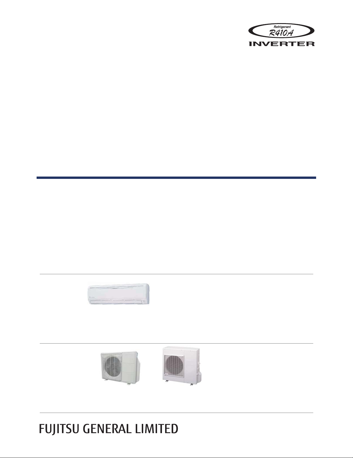
AIR CONDITIONER
Wall Mounted type
DESIGN & TECHNICAL MANUAL
INDOOR
OUTDOOR
ASU18RLB
ASU24RLB
ASU30RLXB
ASU36RLXB
AOU18RLB
AOU24RLB
AOU30RLXB
AOU36RLXB
Page 2

1. INDOOR UNIT
WALL MOUNTED TYPE :
ASU18RLB
ASU24RLB
ASU30RLXB
ASU36RLXB
DTR_AS113E_01
2014.12.26
Page 3

CONTENTS
ASU18-36RL
WALL MOUNTED TYPE
WALL MOUNTED TYPE
ASU18-36RL
1. INDOOR UNIT
1. FEATURE
.................................................................................................................. 01 - 01
2. WIRELESS REMOTE CONTROLLER
3. SPECIFICATIONS
4. DIMENSIONS
5. WIRING DIAGRAMS
6. CAPACITY TABLE
6-1. COOLING CAPACITY
6-2. HEATING CAPACITY
7. FAN PERFORMANCE
7-1. AIR VELOCITY DISTRIBUTION
7-2. AIR FLOW
.......................................................................................................... 01 - 20
8. OPERATION NOISE
8-1. NOISE LEVEL CURVE
8-2. SOUND LEVEL CHECK POINT
.............................................................................................. 01 - 06
........................................................................................................ 01 - 07
........................................................................................ 01 - 09
............................................................................................ 01 - 10
...................................................................................... 01 - 10
....................................................................................... 01 - 14
.................................................................................... 01 - 16
..................................................................... 01 - 16
......................................................................................... 01 - 24
.................................................................................... 01 - 24
..................................................................... 01 - 26
............................................... 01 - 04
9. SAFETY DEVICES
............................................................................................ 01 - 27
10. EXTERNAL INPUT & OUTPUT
10-1. EXTERNAL INPUT
10-2. EXTERNAL OUTPUT
11. FUNCTION SETTING
11-1. INDOOR UNIT (Setting by remote controller)
12. OPTIONAL PARTS
........................................................................................... 01 - 28
....................................................................................... 01 - 30
...................................................................................... 01 - 31
........................................................................................... 01 - 36
............................................................... 01 - 28
........................................... 01 - 31
Page 4
FEATURE1.
MODEL
ASU18RLB
ASU18-36RL
WALL MOUNTED TYPE
ASU24RLB
ASU30RLXB
ASU36RLXB
FEATURES
High energy performance
MODEL
ASU18RLB ASU24RLB ASU30RLXB ASU36RLXB
WALL MOUNTED TYPE
ASU18-36RL
Seasonal Energy Efficiency
Ratio (SEER)
Heating Seasonal Performance
Factor (HSPF)
Energy Efficient Ratio (EER) 12.5 10.0 9.5 8.5
MEASUREMENT CONDITIONS
ANSI/ASHRAE STANDARD 37-1988
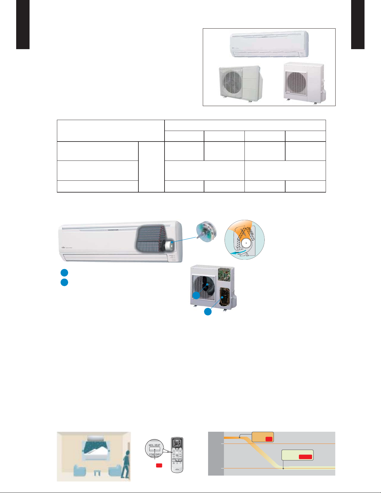
ALL DC
a
DC
fan motor
DC twin rotary compressor
b
More compact compared with conventional model
Super quiet
Btu/hW
19.0 18.0 16.5 15.5
10.6 9.0
High efficiency
layout
Large air flow and quiet
DC fan motor
a
b
Front view
operation by new air
flow path
Air flow mode can be set in 4 steps and more detailed air flow setting is possible.
Easy maintenance
Easy maintenance and always clean. Troublesome maintenance has been made easy.
Since the front panel is easy to remove, maintenance is also easy.
MIN. HEAT Operation
The room temperature can be set to go no lower than 50°F,
thus ensuring that the room does not get too cold when not occupied
Caution)
When the room temperature is higher than 50°F, “MIN. HEAT” operation does not star t. Operation starts and maintains the room temperature
•
at 50°F when the temperature drops below 50°F.
“MIN. HEAT”
ON
Button
Indoor unit
operation START
“MIN. HEAT”
Button
ON
- (01 - 01) -
70
50
°F
°F
Page 5
0
3
(ft)
ASU18-36RL
WALL MOUNTED TYPE
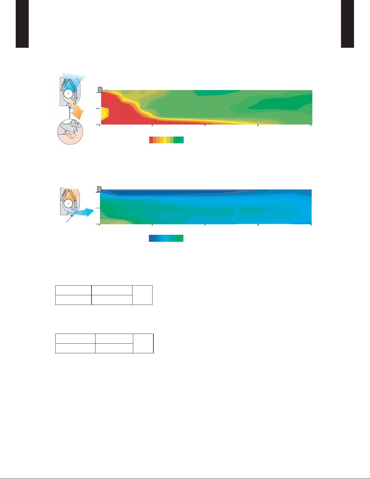
Power diffuser
WALL MOUNTED TYPE
ASU18-36RL
Adoption of large power diffuser
“Strong vertical air flow” provides
powerful floor level heating.
(ft)
16
7
3
Power diffuser
(full open)
0
o
46
Outside air conditions:35.6
Operation contents: Heating,
Set temperature (Max set temp)
86oF ,Air flow Hi,
Vertical airflow direction louver : Downward
Horizontal airflow direction louver : Center
10 20 30 40
o
F 60%
o
(F)
8492 90 88 86
“Healthy horizontal air flow” does not blow
cool air directly at the occupants in the room.
(ft)
7
3
Power diffuser
Low ambient outdoor temperature design
Cooling
Heating
0
Outside air conditions: 95 oF 40%
Operation contents: Cooling,
Set temperature (Min set temp)
o
F ,Air flow Hi,
65
Vertical airflow direction louver : Upward
Horizontal airflow direction louver : Center
14 to 115
5 to 75
10 20 30 40
o
( F)
6559 61 63
°F
(ft)
(ft)
Corresponds to long piping
18, 24 Model
30, 36 Model
65 (20)
164 (50)
ft. (m)
- (01 - 02) -
Page 6
ASU18-36RL
WALL MOUNTED TYPE
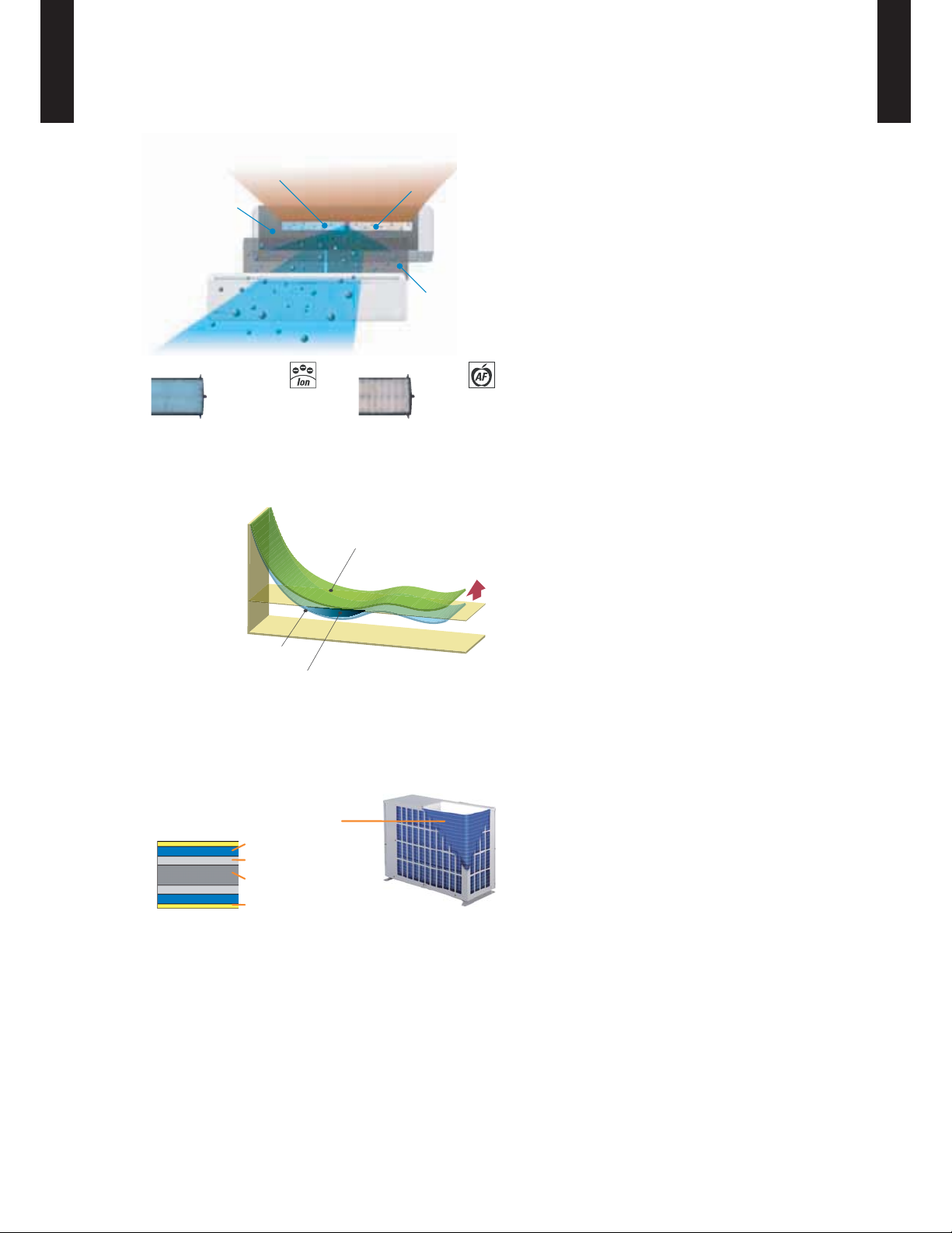
Air conditioner filter features
WALL MOUNTED TYPE
ASU18-36RL
Ion Deodorization Filter
Organic coating fin used
heat exchanger
Long-life Ion
Deodorization Filter
Economy operation
Example : Cooling operation
Temp.
Set temperature
Apple-catechin Filter
Economy operation
Pre Filter
Antibacterial deodorizing
pre-filter with special
ceramic powder
Applecatechin Filter
Shift
setting
temp
Economy operation is energy saving, as ●
the set temperature of indoor unit is shifted
by 2°F and the maximum electric value of
the outdoor unit is suppressed.
Nomal operation
Control maxmum current
Blue fin heat exchanger (30, 36 Model)
Time
Corrosion-resistance of the heat exchanger even in coastal areas has been improved by blue fin
treatment of the outdoor unit heat exchanger.
Blue fin heat exchanger
Cobalt Blue protection
Standard chromate protection
Aluminium base material
Hydrophilic coating
- (01 - 03) -
Page 7
WIRELESS REMOTE CONTROLLER2.
ASU18-36RL
WALL MOUNTED TYPE
FEATURES
Four kinds of timer setup (ON / OFF / PROGRAM / SLEEP) are ●
possible.
Can be used jointly with wired remote controllers . ●
Easy to change custom code (max. 4 custom codes) by button ●
operation.
Built-in timers
Select from four different timer programs (On / Off / Program / Sleep).
Program timer
The program timer operates the ON and OFF timer once within a 24 hour period.
WALL MOUNTED TYPE
ASU18-36RL
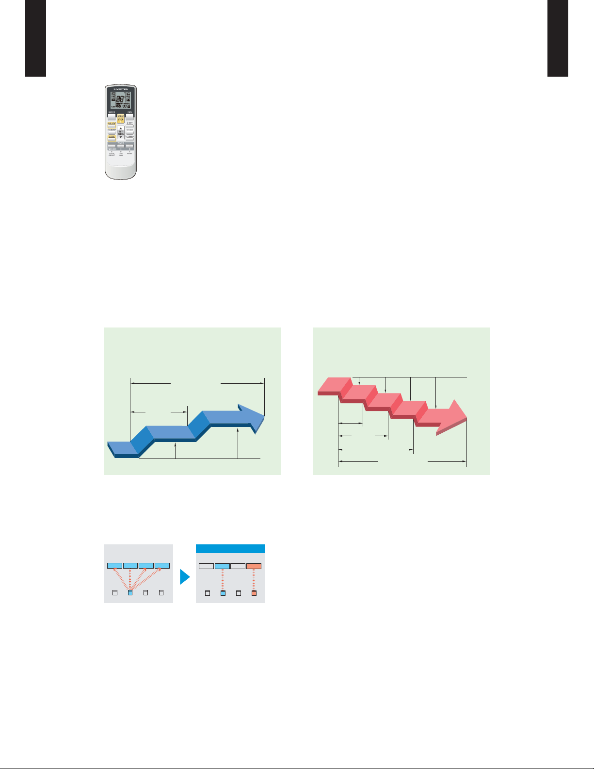
Sleep timer
The sleep timer function automatically corrects the temperature thermostat setting according to the
time setting to prevent excessive cooling and heating while sleeping.
Cooling operation / dry operation
When the sleep timer is set, the set temperature
automatically rises 2°F (1°C) every hour. The set
temperature can rise up to a maximum of 4°F (2°C).
Timer setting
60min.
2°F (1°C)
Simple function setting
4°F (2°C)
Heating operation
When the sleep timer is set, the set temperature
automatically drops 2°F (1°C) every 30 minutes. The
set temperature can drop to a maximum of 8°F (4°C).
2°F (1°C)
4°F (2°C)
6°F (3°C)
8°F (4°C)
30min.
60min.
90min.
Timer setting
Setting of the air conditioner selection function is performed by remote controller.
Switching remote controller custom code
After code change
Mixed-up
I.U. I.U. I.U. I.U.
ABC D
I.U. I.U. I.U. I.U.
ABCD
Code selector switch eliminates unit
•
being wrongly switched.
(Up to 4 codes can be set.)
*I.U.=Indoor unit
- (01 - 04) -
Page 8
ASU18-36RL
WALL MOUNTED TYPE
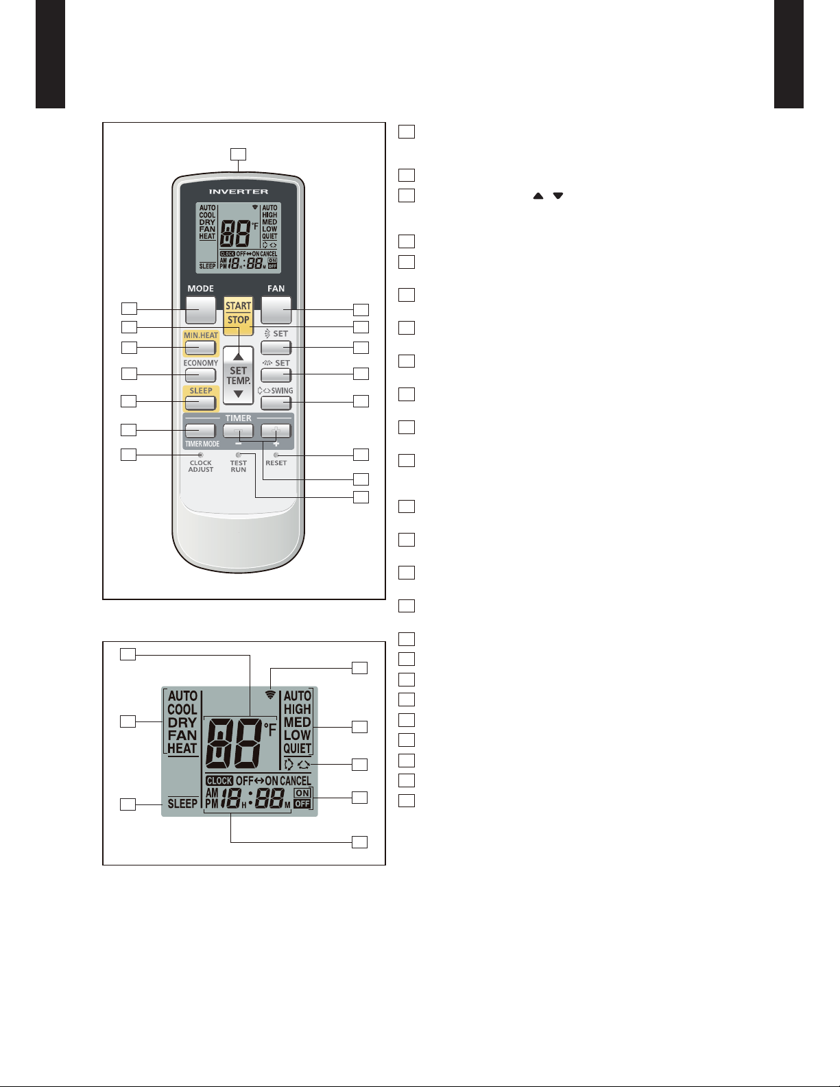
FUNCTIONS
1
3
2
4
5
11
13
Display panel
17
18
19
1
MODE button
16
6
7
8
9
10
14
12
15
20
21
22
23
Selects the operating mode (AUTO, COOL, DRY, FAN, HEAT).
/Start / end R.C. custom code change. (Max 4 types)
2
MIN.HEAT button
3
SET TEMP. button ( / )
Set remote controller custom code buttons
Sets the indoor temp./ Sets R.C. custom code.
4
ECONOMY button
5
SLEEP button
Pressed to select sleep timer.
6
FAN button
Selects the fan speed (AUTO, HIGH, MED, LOW, QUIET).
7
START/STOP button
Pressed to start and stop operation.
8
SET button (Vertical)
Air flow direction vertical set button.
9
SET button (Horizontal)
Air flow direction horizontal set button.
10
SWING button
Air flow direction swing button.
11
TIMER MODE button
Pressed to select the timer mode. (OFF TIMER, ON TIMER,
PROGRAM TIMER, TIMER RESET)
12
TIMER SET ( + / - ) button
Sets the current time and on-off time.
13
CLOCK ADJUST button
Sets the current time.
14
RESET button
Used when replacing batteries.
15
TEST RUN button
Used when testing the air conditioner after installation.
16
Signal transmitter
17
Temperature indicator
18
Mode indicator
19
Sleep indicator
20
Transmit indicator
21
Fan speed indicator
22
Swing indicator
23
Timer mode indicator
24
Clock indicator
WALL MOUNTED TYPE
ASU18-36RL
24
Note: Functions will be different due to type of indoor unit.
For details, please see operation manual.
- (01 - 05) -
Page 9
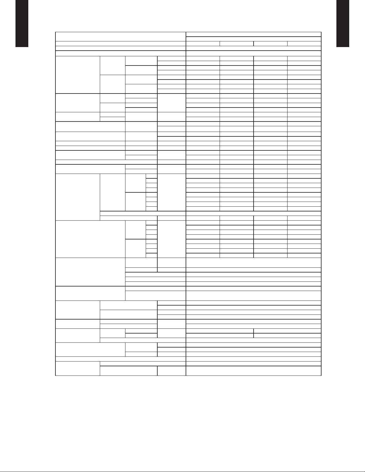
SPECIFICATIONS3.
Typ e
ASU18-36RL
WALL MOUNTED TYPE
Model name ASU18RLB ASU24RLB ASU30RLXB ASU36RLXB
Power source 208/230V ~ 60Hz
Available voltage range 187-253V
Cooling
Capacity
Heating
Input power
Current
EER Cooling
COP Heating
SEER Cooling Btu/hW 19.0 18.0 16.5 15.5
HSPF Heating Btu/hW 10.6 10.6 9.0 9.0
POWER FACTOR
Moistur e removal pints/ h (l/h) 4.0 (1.9) 6.3 (3.0) 9.7 (4.6) 10.1 (4.8)
Maximum operating current *1
Fan
Sound pre ssure level *2
Heat exchanger type
Enclosure
Dimensions
( H×W×D )
Weight
Connection pipe
Operation range
Remote controller type Wireless
Drain pipe
Cooling
Heating
Cooling
Heating 5.8 8.5 12.3 14.8
Airflow
rate
Typ e × Q' ty Cross flow fan × 1
Motor output W 42 42 42 65
Net
Gross
Net
Gross 40 (18)
Size
Method Flare
Material PVC
Size
Rated
Min-Max
Rated
Min-Max
Rated
Max 1.63 2.50 3.42 4.01
Rated 1.285 1.925 2.80 3.39
Max 2.06 2.54 3.28 3.50
Rated A
Cooling
Heating 96 98 99 99
Cooling
Heating 11.8 13.8 18.8 18.8
Cooling
Heating
Cooling
Heating
Dimensions
(H × W × D)
Fin pitch FPI Main:21, Sub:18
Rows x Stages Main:2×18, Sub1:1×4, Sub2:1×4
Pipe type Copper
Fin type Aluminu m
Material Polystyrene
Color
Liquid
Gas Ø 1/2 (Ø 12.70) Ø 5/8 (Ø 15.8 8)
Cooling
Heating °F (°C) 88 (30) or le ss
High
Med 435 (740) 530 (90 0) 530 (90 0) 530 (90 0)
Low 365 (620) 435 (740) 435 (740) 435 (740)
Quiet 306 (520) 365 (620) 36 5 (620) 3 65 (620)
Hig h 541 ( 920) 647 (1,10 0) 67 7 (1,150) 6 94 (1,180)
Med 435 (740) 530 (90 0) 530 (90 0) 530 (90 0)
Low 365 (620) 435 (740) 435 (740) 435 (740)
Quiet 318 (540) 365 (620) 365 (620) 365 (620)
High
Med 35 41 42 42
Low 31 35 37 37
Quiet 26 31 32 32
High 43 47 49 50
Med 36 42 42 42
Low 33 36 37 37
Quiet 28 33 33 33
kW 5.28 7.03 8.79 9.70
Btu/h 18,000 24,000 30,000 33,000
kW 0.90 - 5.28 0.90 - 7.30 2.90 - 9.5 0 2.90 - 10.0 0
Btu/h 3,100 - 19,000 3,100 - 25,000 9,900-32,400 9,900-34,100
kW 5.28 7.03 8.79 9.96
Btu/h 18,000 24,000 30,000 34,000
kW 2.05 - 5.86 2.20 - 7.91 2.34 - 9.70 2.99 - 10. 26
Btu/h 7,000 - 20,000 7,500-27,000 8,000 - 33,000 10,200-35,000
kW
kW/kW 3.67 2.93 2.78 2.50
Btu/hW 12.5 10.0 9.5 8.5
kW /k W 4 .11 3 .6 5 3.1 4 2. 94
Btu/ hW 14.0 12.5 10.7 10.0
%
A
CFM
3
/h)
(m
dB(A)
in. (mm)
mm 32 0 × 998 × 228
inch 12-10/16 × 39 -5/16 × 9
mm 319 × 1090 × 429
inch 12-9/16 × 42 -15/16 × 16-14/16
lbs. (kg)
in. (mm)
°F (°C) 64 to 90 (18 to 32)
%RH 80 or less
mm
(Reference in.)
1.44 2.40 3.16 3.88
6.4 10.5 13.8 17.0
98 99 99 99
8.3 11.8 16 .8 18. 0
541 (920) 659 (1,120) 659 (1,120) 694 (1,180)
42 47 47 50
Main:14-14/16 x 32-12/16 x 1-1/16 (378×832×2 6.6)
Sub: 3- 5/16 x 32-12/16 x 8/16 (84×832×13.3)
Ø 1/4 (Ø 6.35) Ø 3/8 (Ø 9.52)
WALL MO UNTED
INVERTER HEAT PUMP
Approximate color of MUNSELL N9.25/
WHITE
31 (14)
Ø12 (15/32) (I.D.)
Ø16 (5/8) (O.D.)
WALL MOUNTED TYPE
ASU18-36RL
NOTE :
• Specifications are based on the following conditions.
Cooling : Indoor temperature of 80°F (26.67°C) DB / 67°F (19.44°C) WB, and outdoor temperature of 95°F (35°C) DB / 75°F (23.9°C) WB.
Heating : Indoor temperature of 70°F (21.11°C) DB / 59°F (15°C) WB, and outdoor temperature of 47°F (8.33°C) DB / 43°F (6.11°C) WB.
Pipe length : 24ft.7in (7.5m), Height difference:0 m. (Outdoor unit-Indoor unit)
• The protective function might work when using it outside the operation range.
*1: The maximum current is the maximum value when operated within the operation range.
*2: These are the measured values in the manufacturer’s anechoic chamber.
Becaus e of the surrou nding sound env ironment, th e sound levels mea sured in actual installation conditions might be higher than the specified values here.
- (01 - 06) -
Page 10
(
)
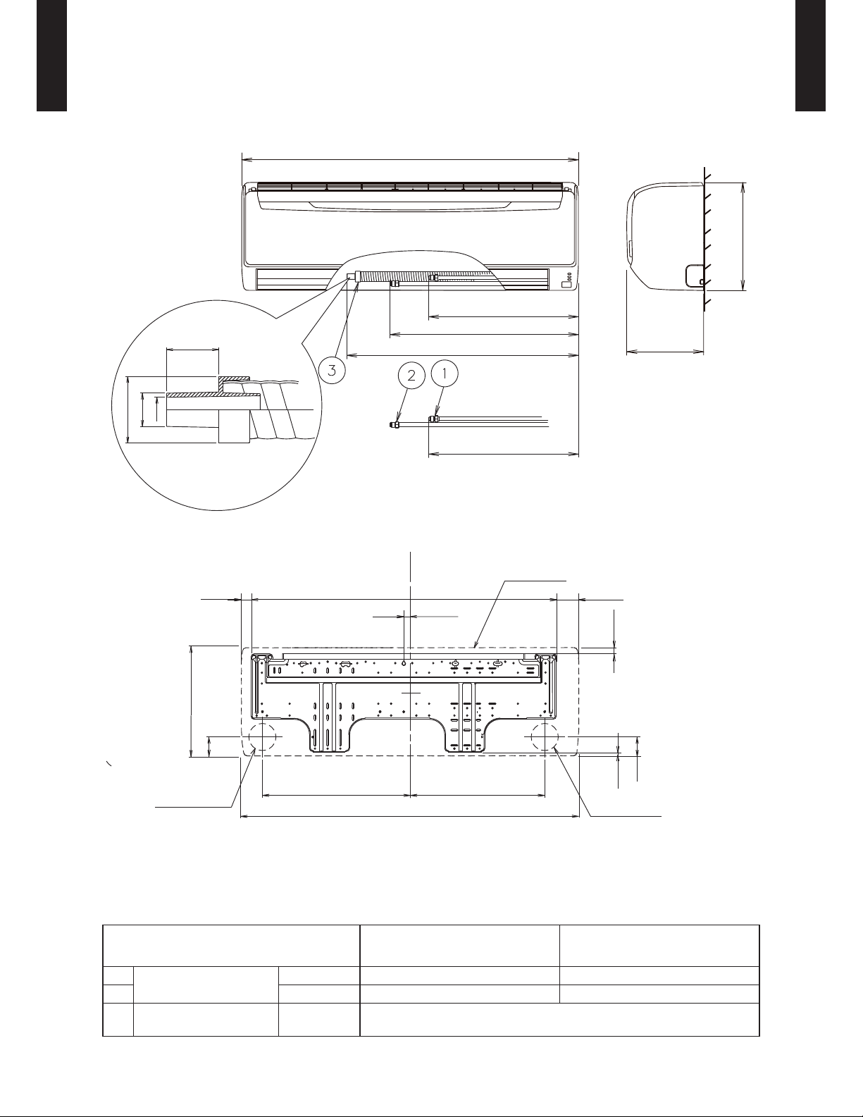
DIMENSIONS4.
ASU18-36RL
WALL MOUNTED TYPE
MODEL : ASU18RLB, ASU24RLB, ASU30RLXB, ASU36RLXB
Unit : in (mm)
39-5/16 (998)
320
12-5/8
20-1/2 (520)
23-1/4 (590)
1 (25)
28-3/8 (721)
9 (228)
WALL MOUNTED TYPE
ASU18-36RL
ø5/8 (16)
ø1-1/4 (32)
ø1/8 (12)
Ø 3-1/8 (80) hole
12-5/8 (320): Unit size
2 (51)
Piping inlet
17-1/4 (438)
Unit center
35-9/16 (903)
13/16 (20)
15-5/8 (397)
39-5/16 (998): Unit size
20-1/2 (520)
Outline of unit
2-5/8 (67)1-1/8 (28)
11/16 (17)
2 (51)
7/16 (11)
Ø 3-1/8 (80) hole
Piping inlet
Refrigerant pipe
flare connection
Drain hose
connection
Liquid
Gas
Drain hose
ASU18RLB
ASU24RLB
ASU30RLXB
ASU36RLXB
Ø 1/4 in. (Ø 6.35 mm) Ø 3/8 in. (Ø 9.52 mm)
Ø 1/2 in. (Ø 12.70 mm) Ø 5/8 in. (Ø15.88 mm)
I.D. Ø 15/32 in. (Ø 12 mm) , O.D. Ø 5/8 in. (Ø 16 mm)
Drain hose : L=26-3/8 in. (670mm)
- (01 - 07) -
Page 11
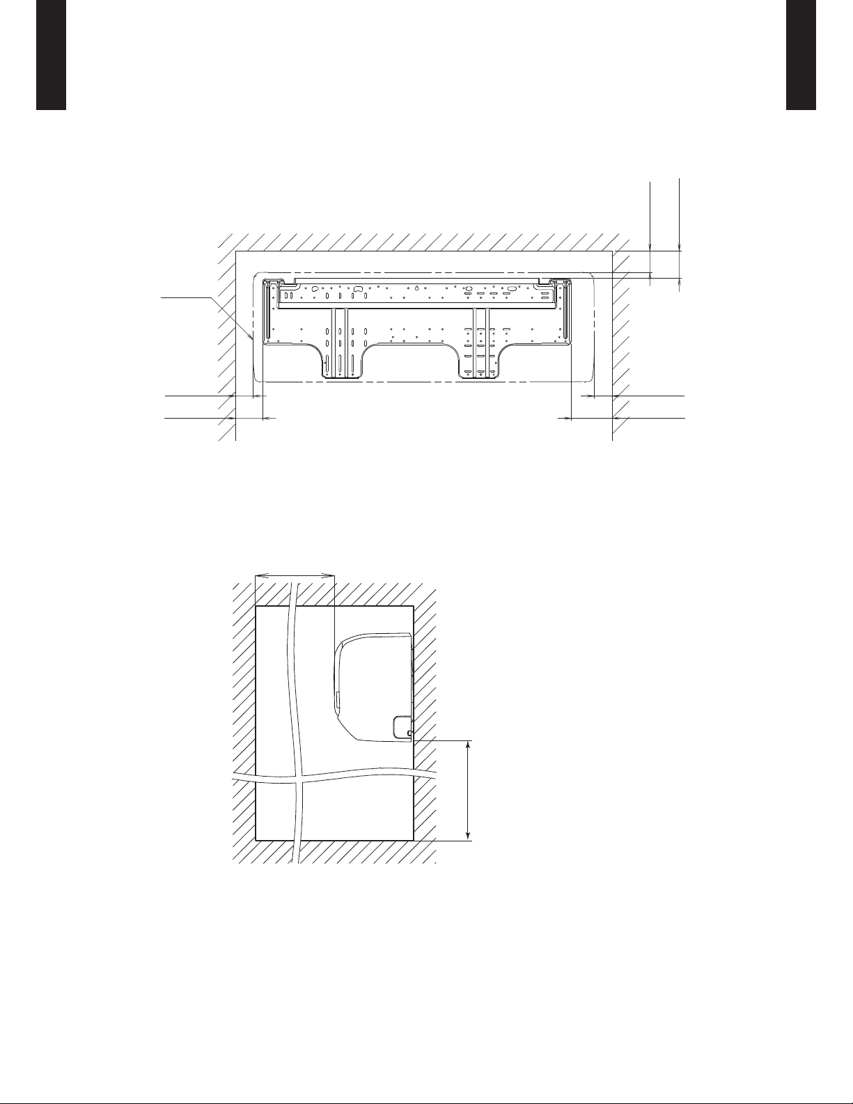
ASU18-36RL
WALL MOUNTED TYPE
INSTALLATION PLACE
WALL MOUNTED TYPE
ASU18-36RL
Unit : in (mm)
4 (80) or more
3 (63) or more
Outline of unit
3 (52) or more 3 (53) or more
4 (80) or more
5 (120) or more
60 (1500) or more
- (01 - 08) -
71 (1800) or more
Page 12
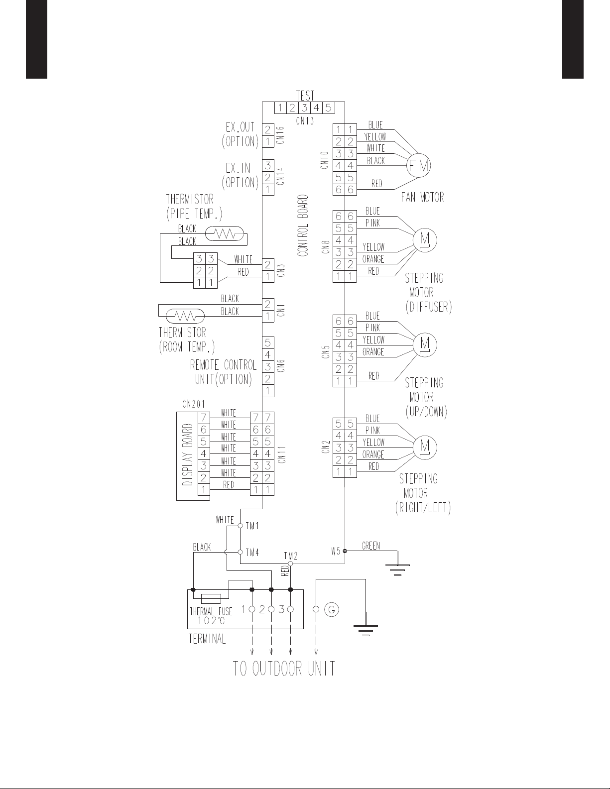
WIRING DIAGRAMS5.
ASU18-36RL
WALL MOUNTED TYPE
MODEL : ASU18RLB, ASU24RLB, ASU30RLXB, ASU36RLXB
WALL MOUNTED TYPE
ASU18-36RL
- (01 - 09) -
Page 13
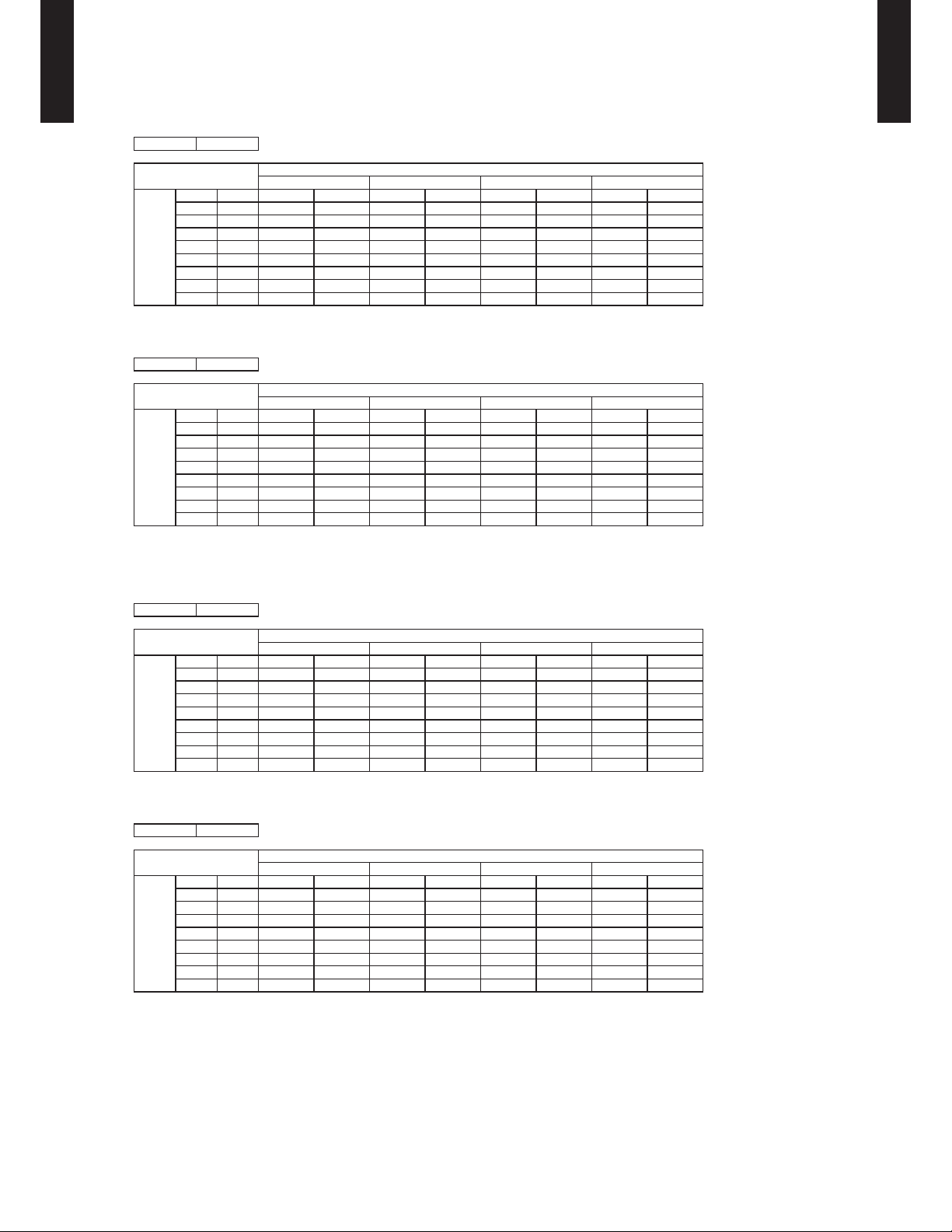
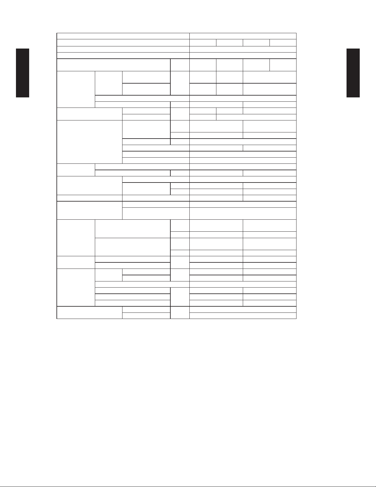
CAPACITY TABLE6.
COOLING CAPACITY6-1.
ASU18-36RL
WALL MOUNTED TYPE
MODEL :ASU18RLB
AFR 541
64°FDB 70°FDB 75°FDB 80°FDB 85°FDB 90°FDB
°FDB TC SHC IP TC SHC IP TC SHC IP TC SHC IP TC SHC IP TC SHC IP
14 15.8 11.8 0.50 17.6 13.1 0.50 19.4 14.5 0.53 20.0 14.9 0.51 21.2 15.8 0.51 22.4 16.7 0.53
23 15.5 11.6 0.54 17.3 12.9 0.54 19.1 14.2 0.57 19.7 14.6 0.56 20.8 15.5 0.56 22.0 16.4 0.58
32 15.3 11.4 0.56 17.0 12.7 0.56 18.8 14.0 0.59 19.4 14.4 0.58 20.5 15.3 0.58 21.7 16.2 0.59
41 15.1 11.2 0.57 16.8 12.5 0.57 18.5 13.8 0.60 19.1 14.2 0.59 20.2 15.1 0.59 21.3 15.9 0.61
50 14.8 11.0 0.58 16.5 12.3 0.59 18.2 13.5 0.62 18.7 14.0 0.60 19.9 14.8 0.60 21.0 15.6 0.62
59 14.6 10.8 0.62 16.2 12.1 0.62 17.9 13.3 0.66 18.4 13.7 0.64 19.5 14.5 0.64 20.7 15.4 0.66
67 16.7 13.3 1.00 18.6 13.4 1.02 20.5 14.6 1.04 21.2 15.8 1.04 22.4 15.7 1.05 23.7 16.8 1.06
77 16.0 12.7 1.13 17.8 12.8 1.14 19.6 13.9 1.17 20.2 15.0 1.17 21.4 15.0 1.18 22.6 16.0 1.19
Outdoor temperature
87 15.2 12.0 1.26 17.0 12.1 1.27 18.7 13.2 1.30 19.3 14.3 1.31 20.5 14.2 1.32 21.6 15.2 1.33
95 14.2 11.3 1.39 15.8 11.4 1.42 17.4 12.4 1.43 18.0 13.4 1.44 19.1 13.3 1.45 20.2 14.2 1.46
104 12.9 9.9 1.37 14.4 10.0 1.39 15.8 10.9 1.42 16.3 11.8 1.42 17.3 11.7 1.43 18.3 12.5 1.45
115 12.0 9.1 1.34 13.4 9.1 1.37 14.8 9.9 1.39 15.2 10.7 1.39 16.1 10.7 1.42 17.0 11.4 1.43
AFR : Air flow rate (CFM)
TC : Total ca pacity (kBtu /h)
SHC : Sensible Heat capacity (kBtu/h)
IP : Input Power (kW )
54°FWB 60°FWB 63°FWB 67°FWB 71°FWB 73°FWB
Indoor temperature
WALL MOUNTED TYPE
ASU18-36RL
AFR 15.3
17.8°CDB 21.1°CDB 23.9°CDB 26.7°CDB 29.4°CDB 32.2°CDB
°CDB TC SHC IP TC SHC IP TC SHC IP TC SHC IP TC SHC IP TC SHC IP
-10.0 4.63 3.45 0.50 5.16 3.85 0.50 5.69 4.24 0.53 5.86 4.37 0.51 6.20 4.62 0.51 6.56 4.89 0.53
-5.0 4.56 3.39 0.54 5.08 3.78 0.54 5.60 4.16 0.57 5.77 4.29 0.56 6.11 4.54 0.56 6.46 4.80 0.58
0.0 4.49 3.34 0.56 5.00 3.72 0.56 5.51 4.10 0.59 5.68 4.23 0.58 6.01 4.48 0.58 6.36 4.74 0.59
5.0 4.41 3.29 0.57 4.92 3.67 0.57 5.42 4.04 0.60 5.59 4.16 0.59 5.92 4.41 0.59 6.25 4.66 0.61
10.0 4.34 3.23 0.58 4.84 3.60 0.59 5.33 3.97 0.62 5.49 4.09 0.60 5.82 4.34 0.60 6.15 4.58 0.62
15.0 4.27 3.18 0.62 4.76 3.54 0.62 5.24 3.90 0.66 5.40 4.02 0.64 5.73 4.26 0.64 6.05 4.50 0.66
19.4 4.90 3.91 1.00 5.46 3.93 1.02 6.02 4.28 1.04 6.21 4.63 1.04 6.58 4.60 1.05 6.95 4.91 1.06
25.0 4.68 3.72 1.13 5.21 3.75 1.14 5.75 4.08 1.17 5.92 4.40 1.17 6.27 4.39 1.18 6.63 4.68 1.19
Outdoor temperature
30.6 4.47 3.52 1.26 4.98 3.55 1.27 5.49 3.87 1.30 5.66 4.18 1.31 5.99 4.17 1.32 6.34 4.44 1.33
35.0 4.17 3.31 1.39 4.64 3.34 1.42 5.11 3.64 1.43 5.28 3.93 1.44 5.59 3.91 1.45 5.91 4.17 1.46
40.0 3.78 2.92 1.37 4.21 2.93 1.39 4.64 3.20 1.42 4.78 3.45 1.42 5.07 3.44 1.43 5.35 3.66 1.45
46.1 3.52 2.66 1.34 3.92 2.67 1.37 4.32 2.92 1.39 4.45 3.14 1.39 4.73 3.13 1.42 4.99 3.34 1.43
AFR : Air flow rate (m
TC : Total ca pacity (kW)
SHC : Sensible Heat capacity (kW)
IP : Input Power (kW )
12.2°CWB 15.6°CWB 17.7°CWB 19.4°CWB 21.7°CWB 22.8°CWB
3
/min)
Indoor temperature
- (01 - 10) -
Page 14
ASU18-36RL
WALL MOUNTED TYPE
MODEL : ASU24RLB
AFR 659
64°FDB 70°FDB 75°FDB 80°FDB 85°FDB 90°FDB
°FDB TC SHC IP TC SHC IP TC SHC IP TC SHC IP TC SHC IP TC SHC IP
14 21.1 14.9 0.83 23.5 16.6 0.84 25.9 18.3 0.88 26.6 18.9 0.86 28.2 20.0 0.86 29.8 21.2 0.89
23 20.7 14.7 0.90 23.1 16.3 0.90 25.5 18.0 0.95 26.2 18.6 0.93 27.8 19.7 0.93 29.4 20.8 0.96
32 20.4 14.5 0.93 22.7 16.1 0.94 25.1 17.8 0.99 25.8 18.3 0.96 27.3 19.4 0.96 28.9 20.5 0.99
41 20.1 14.2 0.95 22.4 15.9 0.95 24.7 17.5 1.00 25.4 18.0 0.98 26.9 19.1 0.98 28.5 20.2 1.01
50 19.7 14.0 0.97 22.0 15.6 0.98 24.3 17.2 1.03 25.0 17.7 1.00 26.5 18.8 1.01 28.0 19.8 1.04
59 19.7 13.7 1.04 21.9 15.3 1.04 24.2 16.9 1.10 24.9 17.4 1.07 26.4 18.4 1.07 27.9 19.5 1.10
67 22.3 16.9 1.67 24.8 17.0 1.71 27.4 18.5 1.73 28.2 20.0 1.73 29.9 19.9 1.75 31.6 21.3 1.77
77 21.3 16.1 1.88 23.7 16.2 1.90 26.1 17.7 1.94 26.9 19.1 1.94 28.5 19.0 1.96 30.2 20.2 1.98
Outdoor temperature
87 20.2 15.3 2.10 22.5 15.4 2.12 24.8 16.8 2.16 25.5 18.1 2.18 27.0 18.0 2.20 28.6 19.2 2.22
95 19.0 14.3 2.32 21.1 14.4 2.36 23.3 15.7 2.38 24.0 17.0 2.40 25.4 16.9 2.42 26.9 18.0 2.44
104 17.1 12.6 2.28 19.1 12.7 2.32 21.0 13.9 2.36 21.6 14.9 2.36 22.9 14.9 2.38 24.2 15.8 2.42
115 16.1 11.5 2.24 17.9 11.5 2.28 19.7 12.6 2.32 20.3 13.6 2.32 21.6 13.5 2.36 22.7 14.4 2.38
AFR : Air flow rate (CFM)
TC : Total ca pacity (kBtu /h)
SHC : Sensible Heat capacity (kBtu/h)
IP : Input Power (kW )
54°FWB 60°FWB 63°FWB 67°FWB 71°FWB 73°FWB
Indoor temperature
WALL MOUNTED TYPE
ASU18-36RL
AFR 18.7
17.8°CDB 21.1°CDB 23.9°CDB 26.7°CDB 29.4°CDB 32.2°CDB
°CDB TC SHC IP TC SHC IP TC SHC IP TC SHC IP TC SHC IP TC SHC IP
-10.0 6.17 4.38 0.83 6.88 4.88 0.84 7.58 5.38 0.88 7.81 5.54 0.86 8.27 5.87 0.86 8.74 6.20 0.89
-5.0 6.08 4.30 0.90 6.77 4.79 0.90 7.46 5.28 0.95 7.69 5.44 0.93 8.14 5.76 0.93 8.61 6.09 0.96
0.0 5.98 4.24 0.93 6.66 4.72 0.94 7.34 5.21 0.99 7.57 5.37 0.96 8.02 5.68 0.96 8.47 6.01 0.99
5.0 5.88 4.17 0.95 6.55 4.65 0.95 7.23 5.12 1.00 7.45 5.28 0.98 7.89 5.60 0.98 8.34 5.91 1.01
10.0 5.79 4.10 0.97 6.45 4.57 0.98 7.11 5.04 1.03 7.33 5.19 1.00 7.76 5.50 1.01 8.20 5.81 1.04
15.0 5.77 4.03 1.04 6.43 4.49 1.04 7.09 4.95 1.10 7.31 5.10 1.07 7.75 5.40 1.07 8.19 5.71 1.10
19.4 6.54 4.96 1.67 7.28 4.99 1.71 8.03 5.43 1.73 8.28 5.87 1.73 8.77 5.84 1.75 9.27 6.23 1.77
25.0 6.24 4.72 1.88 6.95 4.75 1.90 7.66 5.18 1.94 7.89 5.59 1.94 8.36 5.57 1.96 8.84 5.93 1.98
Outdoor temperature
30.6 5.91 4.47 2.10 6.59 4.50 2.12 7.27 4.91 2.16 7.48 5.30 2.18 7.93 5.29 2.20 8.39 5.63 2.22
35.0 5.56 4.20 2.32 6.19 4.23 2.36 6.82 4.61 2.38 7.03 4.99 2.40 7.45 4.96 2.42 7.88 5.29 2.44
40.0 5.01 3.70 2.28 5.58 3.71 2.32 6.14 4.06 2.36 6.33 4.38 2.36 6.72 4.36 2.38 7.09 4.64 2.42
46.1 4.71 3.37 2.24 5.23 3.38 2.28 5.77 3.70 2.32 5.95 3.98 2.32 6.32 3.97 2.36 6.67 4.23 2.38
AFR : Air flow rate (m
TC : Total ca pacity (kW)
SHC : Sensible Heat capacity (kW)
IP : Input Power (kW )
12.2°CWB 15.6°CWB 17.7°CWB 19.4°CWB 21.7°CWB 22.8°CWB
3
/min)
Indoor temperature
- (01 - 11) -
Page 15

ASU18-36RL
WALL MOUNTED TYPE
MODEL :ASU30 RLXB
AFR 659
64°FDB 70°FDB 75°FDB 80°FDB 85°FDB 90°FDB
°FDB TC SHC IP TC SHC IP TC SHC IP TC SHC IP TC SHC IP TC SHC IP
14 25.7 18.3 0.80 28.6 18.4 0.81 31.5 20.1 0.82 32.5 21.7 0.83 34.5 21.6 0.84 36.4 23.0 0.84
23 25.7 18.7 0.93 28.6 18.8 0.94 31.5 20.5 0.95 32.5 22.1 0.96 34.5 22.0 0.97 36.4 23.5 0.98
32 25.7 19.0 1.05 28.6 19.2 1.07 31.5 20.9 1.08 32.5 22.6 1.09 34.4 22.5 1.10 36.4 23.9 1.11
41 25.7 18.3 1.17 28.6 18.4 1.19 31.5 20.1 1.21 32.5 21.7 1.22 34.4 21.6 1.23 36.4 23.0 1.24
50 25.6 18.7 1.33 28.5 18.8 1.35 31.4 20.5 1.37 32.4 22.1 1.37 34.3 22.0 1.39 36.3 23.5 1.40
59 25.1 18.2 1.47 28.0 18.4 1.49 30.8 20.0 1.51 31.8 21.6 1.52 33.7 21.5 1.53 35.6 22.9 1.55
67 24.4 18.0 1.71 27.2 18.2 1.74 30.0 19.8 1.76 30.9 21.4 1.77 32.8 21.3 1.79 34.7 22.7 1.81
77 26.3 19.1 2.45 29.3 19.2 2.49 32.4 20.9 2.53 33.4 22.6 2.54 35.4 22.5 2.57 37.4 24.0 2.59
Outdoor temperature
87 25.1 18.4 2.74 27.9 18.5 2.79 30.8 20.2 2.83 31.7 21.8 2.84 33.6 21.7 2.87 35.5 23.1 2.90
95 23.7 17.6 3.05 26.4 17.7 3.10 29.1 19.4 3.14 30.0 20.9 3.16 31.8 20.8 3.19 33.6 22.2 3.22
104 22.1 16.8 3.35 24.7 16.9 3.40 27.2 18.4 3.45 28.0 19.9 3.47 29.7 19.8 3.50 31.4 21.1 3.54
115 16.9 14.0 2.80 18.8 14.1 2.84 20.7 15.4 2.88 21.3 16.6 2.90 22.6 16.6 2.93 23.9 17.7 2.96
AFR : Air flow rate (CFM)
TC : Total ca pacity (kBtu /h)
SHC : Sensible Heat capacity (kBtu/h)
IP : Input Power (kW )
54°FWB 60°FWB 63°FWB 67°FWB 71°FWB 73°FWB
Indoor temperature
WALL MOUNTED TYPE
ASU18-36RL
AFR 18.7
17.8°CDB 21.1°CDB 23.9°CDB 26.7°CDB 29.4°CDB 32.2°CDB
°CDB TC SHC IP TC SHC IP TC SHC IP TC SHC IP TC SHC IP TC SHC IP
-10.0 7.53 5.37 0.80 8.39 5.40 0.81 9.25 5.89 0.82 9.53 6.36 0.83 10.10 6.34 0.84 10.68 6.75 0.84
-5.0 7.53 5.48 0.93 8.38 5.51 0.94 9.24 6.01 0.95 9.53 6.49 0.96 10.10 6.46 0.97 10.67 6.88 0.98
0.0 7.52 5.58 1.05 8.38 5.61 1.07 9.24 6.12 1.08 9.52 6.61 1.09 10.09 6.59 1.10 10.66 7.02 1.11
5.0 7.52 5.36 1.17 8.37 5.40 1.19 9.23 5.88 1.21 9.52 6.35 1.22 10.09 6.33 1.23 10.66 6.74 1.24
10.0 7.50 5.47 1.33 8.35 5.51 1.35 9.21 6.01 1.37 9.49 6.49 1.37 10.06 6.46 1.39 10.63 6.88 1.40
15.0 7.36 5.35 1.47 8.20 5.38 1.49 9.03 5.87 1.51 9.31 6.34 1.52 9.87 6.31 1.53 10.43 6.72 1.55
19.4 7.16 5.29 1.71 7.98 5.32 1.74 8.80 5.80 1.76 9.07 6.27 1.77 9.61 6.24 1.79 10.16 6.65 1.81
25.0 7.72 5.60 2.45 8.60 5.63 2.49 9.48 6.14 2.53 9.77 6.63 2.54 10.36 6.60 2.57 10.95 7.03 2.59
Outdoor temperature
30.6 7.35 5.39 2.74 8.19 5.42 2.79 9.02 5.91 2.83 9.30 6.39 2.84 9.86 6.36 2.87 10.42 6.78 2.90
35.0 6.94 5.17 3.05 7.74 5.20 3.10 8.53 5.67 3.14 8.79 6.12 3.16 9.32 6.10 3.19 9.84 6.50 3.22
40.0 6.49 4.93 3.35 7.23 4.95 3.40 7.97 5.40 3.45 8.22 5.84 3.47 8.71 5.81 3.50 9.20 6.19 3.54
46.1 4.94 4.12 2.80 5.51 4.14 2.84 6.07 4.52 2.88 6.26 4.88 2.90 6.63 4.86 2.93 7.01 5.17 2.96
AFR : Air flow rate (m
TC : Total ca pacity (kW)
SHC : Sensible Heat capacity (kW)
IP : Input Power (kW )
12.2°CWB 15.6°CWB 17.7°CWB 19.4°CWB 21.7°CWB 22.8°CWB
3
/min)
Indoor temperature
- (01 - 12) -
Page 16

ASU18-36RL
WALL MOUNTED TYPE
MODEL :ASU36 RLXB
AFR 659
64°FDB 70°FDB 75°FDB 80°FDB 85°FDB 90°FDB
°FDB TC SHC IP TC SHC IP TC SHC IP TC SHC IP TC SHC IP TC SHC IP
14 27.6 19.9 1.01 30.8 20.0 1.03 33.9 21.9 1.04 35.0 23.6 1.05 37.1 23.5 1.06 39.2 25.1 1.07
23 27.6 20.3 1.17 30.8 20.4 1.19 33.9 22.3 1.21 34.9 24.1 1.21 37.0 24.0 1.22 39.1 25.5 1.24
32 27.6 20.7 1.33 30.7 20.8 1.35 33.9 22.7 1.37 34.9 24.5 1.38 37.0 24.4 1.39 39.1 26.0 1.41
41 27.6 19.9 1.48 30.7 20.0 1.51 33.9 21.8 1.53 34.9 23.6 1.54 37.0 23.5 1.55 39.1 25.0 1.57
50 27.5 20.3 1.68 30.6 20.4 1.70 33.8 22.3 1.73 34.8 24.0 1.74 36.9 23.9 1.76 39.0 25.5 1.77
59 27.3 20.2 1.85 30.4 20.3 1.88 33.6 22.1 1.91 34.6 23.9 1.92 36.7 23.8 1.94 38.7 25.4 1.96
67 26.3 19.6 2.16 29.3 19.7 2.20 32.3 21.5 2.23 33.3 23.2 2.24 35.3 23.1 2.27 37.3 24.6 2.29
77 28.3 20.8 3.10 31.6 20.9 3.15 34.8 22.8 3.20 35.9 24.6 3.21 38.0 24.5 3.25 40.2 26.1 3.28
Outdoor temperature
87 27.0 20.0 3.47 30.0 20.1 3.52 33.1 21.9 3.58 34.1 23.7 3.60 36.2 23.6 3.63 38.2 25.1 3.67
95 25.5 19.2 3.86 28.4 19.3 3.92 31.3 21.0 3.98 33.0 21.8 3.88 34.2 22.6 4.04 36.1 24.1 4.08
104 23.8 18.2 4.23 26.5 18.3 4.30 29.2 20.0 4.37 30.1 21.6 4.39 31.9 21.5 4.43 33.8 22.9 4.48
115 18.1 15.2 3.54 20.2 15.3 3.59 22.3 16.7 3.65 22.9 18.0 3.67 24.3 17.9 3.70 25.7 19.1 3.74
AFR : Air flow rate (CFM)
TC : Total ca pacity (kBtu /h)
SHC : Sensible H eat capacity ( kBtu/h)
IP : Input Power (kW )
54°FWB 60°FWB 63°FWB 67°FWB 71°FWB 73°FWB
Indoor temperature
WALL MOUNTED TYPE
ASU18-36RL
AFR 19.7
17.8°CDB 21.1°CDB 23.9°CDB 26.7°CDB 29.4°CDB 32.2°CDB
°CDB TC SHC IP TC SHC IP TC SHC IP TC SHC IP TC SHC IP TC SHC IP
-10.0 8.10 5.84 1.01 9.02 5.88 1.03 9.94 6.41 1.04 10.25 6.92 1.05 10.86 6.89 1.06 11.48 7.34 1.07
-5.0 8.09 5.95 1.17 9.01 5.99 1.19 9.94 6.53 1.21 10.24 7.05 1.21 10.86 7.02 1.22 11.47 7.48 1.24
0.0 8.09 6.06 1.33 9.01 6.10 1.35 9.93 6.65 1.37 10.24 7.18 1.38 10.85 7.15 1.39 11.47 7.62 1.41
5.0 8.08 5.83 1.48 9.00 5.87 1.51 9.92 6.40 1.53 10.23 6.91 1.54 10.84 6.88 1.55 11.46 7.33 1.57
10.0 8.06 5.95 1.68 8.98 5.98 1.70 9.90 6.53 1.73 10.21 7.05 1.74 10.82 7.02 1.76 11.43 7.48 1.77
15.0 8.01 5.92 1.85 8.92 5.95 1.88 9.83 6.49 1.91 10.14 7.01 1.92 10.75 6.98 1.94 11.35 7.44 1.96
19.4 7.70 5.75 2.16 8.58 5.78 2.20 9.46 6.30 2.23 9.75 6.81 2.24 10.33 6.78 2.27 10.92 7.22 2.29
25.0 8.30 6.08 3.10 9.25 6.12 3.15 10.19 6.67 3.20 10.51 7.21 3.21 11.14 7.18 3.25 11.77 7.65 3.28
Outdoor temperature
30.6 7.90 5.86 3.47 8.80 5.89 3.52 9.70 6.43 3.58 10.00 6.94 3.60 10.60 6.91 3.63 11.20 7.36 3.67
35.0 7.47 5.61 3.86 8.32 5.65 3.92 9.17 6.16 3.98 9.70 6.39 3.88 10.02 6.62 4.04 10.58 7.06 4.08
40.0 6.98 5.35 4.23 7.77 5.38 4.30 8.57 5.87 4.37 8.83 6.33 4.39 9.36 6.31 4.43 9.89 6.72 4.48
46.1 5.31 4.45 3.54 5.92 4.48 3.59 6.52 4.89 3.65 6.73 5.28 3.67 7.13 5.26 3.70 7.53 5.60 3.74
AFR : Air flow rate (m
TC : Total ca pacity (kW)
SHC : Sensible Heat capacity (kW)
IP : Input Power (kW )
12.2°CWB 15.6°CWB 17.7°CWB 19.4°CWB 21.7°CWB 22.8°CWB
3
/min)
Indoor temperature
- (01 - 13) -
Page 17

HEATING CAPACITY6-2.
ASU18-36RL
WALL MOUNTED TYPE
MODEL :ASU18R LB
AFR 5 41
°FDB °FWB TC IP TC IP TC IP TC IP
5 3 16.2 1.98 15.8 2.01 15.4 2.18 14.6 2.14
14 12 17.3 1. 87 16.9 1.90 16. 5 2.13 15.6 2.02
23 19 18.1 1.81 17.7 1. 84 17.2 2.05 16.3 1.96
32 28 18 .2 1.81 17.8 1.85 17.3 1.95 16.5 1.9 6
41 37 19.9 1. 92 19.4 1.95 19 .0 2.00 18. 0 2.08
47 43 21.0 1.98 20.5 2.01 20.0 2.06 19.0 2.14
50 47 23.2 2.01 22.7 2.04 22.1 2.09 21.0 2.17
Outdoo r temperature
AFR: Air flow ra te (CFM)
TC : Total ca pacity (kBtu /h)
IP : Input Power (kW )
AFR : Air flow rate (m3/min)
TC : Total capa city (kW)
IP : Inpu t Power (kW)
59 50 24.0 2.05 23.4 2.09 22.9 2.10 21.8 2.22
AFR 15.3
°CDB °CWB TC IP TC IP TC IP TC I P
-15.0 -16.1 4.73 1.98 4.64 2.01 4.51 2.18 4.29 2.14
-10.0 -11.1 5. 08 1. 87 4.95 1.90 4.83 2.13 4.5 9 2.0 2
-5.0 -7.2 5.3 0 1.81 5.17 1.84 5.03 2.05 4.78 1.96
0.0 - 2.2 5. 35 1.81 5.22 1. 85 5.08 1.95 4. 83 1.96
5.0 2.8 5.8 4 1.92 5.69 1.95 5.57 2.00 5.27 2.08
8.3 6.1 6.16 1.98 6.01 2.01 5.86 2.06 5.57 2.14
10.0 8.3 6.79 2.01 6.65 2.04 6.47 2.09 6.16 2.17
Outdoo r temperature
15.0 10.0 7.04 2.05 6. 87 2.09 6.72 2.10 6.3 8 2.2 2
60°FDB 65°FDB 70°FDB 75°FDB
15.6°CDB 18.3°CDB 21.1°CDB 23.9°CDB
Indoor temperature
Indoor temperature
WALL MOUNTED TYPE
ASU18-36RL
MODEL :ASU2 4RLB
AFR 647
°FDB °FWB TC IP TC IP TC IP TC IP
5 3 21.8 2.44 21.4 2.48 20.8 2.69 19.8 2.64
14 12 23.4 2.30 22.8 2.34 22.3 2.62 21.1 2.49
23 19 24.4 2.23 23.8 2.27 23.2 2.53 22.0 2.41
32 28 24.6 2.23 24.1 2.28 23.4 2.40 22.3 2.42
41 37 26.9 2.37 26.2 2.41 25.6 2. 46 24.3 2.56
47 43 28.4 2.44 27.7 2.48 27.0 2.54 25.6 2.64
50 47 31.3 2.48 30.6 2.52 29.8 2.58 28.4 2.68
Outdoo r temperature
AFR: Air flow ra te (CFM)
TC : Total capa city (kBtu/ h)
IP : Inpu t Power (kW)
AFR : Air flow rate (m
TC : Total capa city (kW)
IP : Inpu t Power (kW)
59 50 32.4 2.53 31.6 2.57 31.0 2.59 29.4 2.73
AFR 18.3
°CDB °CWB TC IP TC IP TC IP TC I P
-15.0 -16.1 6.39 2.44 6.26 2.48 6.09 2.69 5.79 2.64
-10.0 -11.1 6. 85 2.30 6.6 9 2. 34 6 .52 2.62 6.19 2. 49
-5.0 -7.2 7.15 2.23 6.99 2.27 6.79 2.53 6.46 2.41
0.0 -2.2 7.22 2.23 7.05 2.28 6.85 2.40 6.52 2.42
5.0 2.8 7.88 2.37 7.68 2.41 7.52 2.46 7.12 2. 56
8.3 6.1 8.31 2.44 8.11 2.48 7.91 2.54 7.52 2.64
10.0 8.3 9.17 2.48 8.97 2.52 8.74 2.58 8.31 2.68
Outdoo r temperature
15.0 10.0 9.50 2.53 9. 27 2.57 9.07 2.59 8.61 2.73
3
/min)
60°FDB 65°FDB 70°FDB 75°FDB
15.6°CDB 18.3°CDB 21.1°CDB 23.9°CDB
Indoor temperature
Indoor temperature
- (01 - 14) -
Page 18
ASU18-36RL
WALL MOUNTED TYPE
MODEL :ASU3 0RL XB
AFR 677
°FDB °FWB TC IP TC IP TC IP TC IP
5 3 23.2 3.78 22.7 3.86 22.1 3.94 21.0 4.10
14 12 25.0 3.78 24.4 3.86 23.8 3.93 22.6 4.09
23 19 28.8 3.79 28.1 3.87 27.5 3.95 26.1 4.11
32 28 31.6 3.76 30.9 3.84 30.1 3.91 28.6 4.07
41 37 34.6 3.80 33.8 3.88 32.9 3.96 31.3 4.12
47 43 34.7 3.15 33.8 3.21 33.0 3.28 31.4 3.41
50 47 35.7 3.14 34.8 3.20 3 4.0 3. 27 32.3 3.40
Outdoo r temperature
AFR: Air flow ra te (CFM)
TC : Total capa city (kBtu/ h)
IP : Inpu t Power (kW)
AFR : Air flow rate (m3/min)
TC : Total capa city (kW)
IP : Inpu t Power (kW)
59 50 34.4 2.74 33.6 2.80 32.8 2.86 31.1 2.97
AFR 19.2
°CDB °CWB TC IP TC IP TC IP TC I P
-15.0 -16.1 6.81 3.78 6.65 3.86 6.48 3.94 6.16 4.10
-10.0 -11.1 7. 33 3.78 7.15 3.8 6 6 .98 3.93 6.6 3 4. 09
-5.0 -7.2 8.45 3.79 8.25 3.87 8.05 3.95 7.65 4.11
0.0 -2.2 9.27 3.76 9.05 3.8 4 8.83 3.91 8.38 4.07
5.0 2.8 10.14 3.8 0 9.90 3.88 9.66 3.9 6 9.17 4.12
8.3 6.1 10 .16 3 .15 9.91 3.21 9.70 3.28 9 .19 3.41
10.0 8. 3 10. 46 3.14 10.21 3. 20 9.9 6 3.27 9.47 3.4 0
Outdoo r temperature
15.0 10.0 10.09 2.74 9.85 2.8 0 9.61 2.86 9.13 2.97
60°FDB 65°FDB 70°FDB 75°FDB
15.6°CDB 18.3°CDB 21.1°CDB 23.9°CDB
Indoor temperature
Indoor temperature
WALL MOUNTED TYPE
ASU18-36RL
MODEL :ASU3 6RL XB
AFR 695
°FDB °FWB TC IP TC IP TC IP TC IP
5 3 24.6 4.04 24.1 4.12 23.5 4.20 22.3 4.28
14 12 26.5 4.03 25.9 4.11 25.3 4.20 24.0 4.28
23 19 30.6 4.05 29. 9 4.13 29.1 4.22 27.7 4.28
32 28 33.5 4.01 32.7 4.09 31.9 4.18 30.3 4.28
41 37 36.7 4.06 35.8 4.14 34.9 4.23 33. 2 4.28
47 43 36.8 3.36 35.9 3.43 35.0 3.50 33.3 3.64
50 47 37.9 3.35 37.0 3.42 36.1 3.49 34.3 3.63
Outdoo r temperature
AFR: Air flow ra te (CFM)
TC : Total capa city (kBtu/ h)
IP : Inpu t Power (kW)
AFR : Air flow rate (m
TC : Total capa city (kW)
IP : Inpu t Power (kW)
59 50 36.5 2.92 35.6 2.99 34.8 3.05 33.0 3.17
AFR 19.7
°CDB °CWB TC IP TC IP TC IP TC I P
-15.0 -16.1 7.22 4.04 7.05 4.12 6.88 4.20 6.5 3 4.28
-10.0 -11.1 7.77 4.03 7.59 4.11 7.40 4.20 7.03 4.28
-5.0 -7.2 8.96 4.05 8.75 4.13 8.54 4.22 8.11 4.28
0.0 -2.2 9.83 4.01 9.59 4.09 9.36 4.18 8.89 4.28
5.0 2.8 10.75 4.06 10.50 4.14 10. 24 4. 23 9.73 4 .28
8.3 6.1 10.77 3. 36 10.51 3.4 3 10.26 3.5 0 9.75 3.64
10.0 8. 3 11.10 3.3 5 10.83 3.42 10 .57 3 .49 10. 04 3. 63
Outdoo r temperature
15.0 10.0 10.70 2.9 2 10.45 2.9 9 10.19 3.05 9.68 3.17
3
/min)
60°FDB 65°FDB 70°FDB 75°FDB
15.6°CDB 18.3°CDB 21.1°CDB 23.9°CDB
Indoor temperature
Indoor temperature
- (01 - 15) -
Page 19

FAN PERFORMANCE7.
AIR VELOCITY DISTRIBUTION7-1.
ASU18-36RL
WALL MOUNTED TYPE
MODEL :ASU18RLB
(m)
(ft)
2
7
1
3
0
0
1
3
2
7
012345678
(m)
(ft)
3
10
2
7
7(2) 3(1) 2(0.5)
7142027
Unit : ft/s (m/s)
Unit : ft/s (m/s)
TOP VIEW
Vert ical air flow directio n louver : Up
Horizontal airflow d irection lou ver : Center
(m)
(ft)
Conditions:
Fan speed : High
Operation mode : FAN
Volt age : 2 30V
WALL MOUNTED TYPE
ASU18-36RL
7(2)
1
3
0
0
012345678
(ft)
(m)
3
10
3(1)
2(0.5)
SIDE VIEW
Vert ical air flow directio n louver : Up
Horizontal airflow d irection lou ver : Center
(m)
7142027
(ft)
Unit : ft/s (m/s)
2
7
7(2)
1
3
0
0
3(1)
2(0.5)
2(0.5)
1
3
7
10
(ft)
10
7
3
0
7(2)
2
3
012345678
(m)
3
2
1
0
012345678
3(1)
7142027
Unit : ft/s (m/s)
7(2)
3(1)
7142027
2(0.5)
TOP VIEW
Vert ical air flow directio n louver : Up
Horizontal airflow d irection lou ver : Right & Left
(m)
(ft)
SIDE VIEW
Vert ical air flow directio n louver : Down
Horizontal airflow d irection lou ver : Center
(m)
(ft)
- (01 - 16) -
Page 20

Conditions:
ASU18-36RL
WALL MOUNTED TYPE
MODEL : ASU24RLB
(m)
(ft)
2
7
1
3
0
0
7(2) 3(1)
Unit : ft/s (m/s)
Fan speed : High
Operation mode : FAN
Volt age : 2 30V
WALL MOUNTED TYPE
ASU18-36RL
2(0.5)
1
3
TOP VIEW
Vert ical air flow directio n louver : Up
2
7
012345678
7142027
(ft)
10
(m)
3
Unit : ft/s (m/s)
Horizontal airflow d irection lou ver : Center
(m)
(ft)
2
7
7(2)
1
3
3(1)
2(0.5)
0
0
012345678
7142027
(ft)
(m)
3
10
Unit : ft/s (m/s)
3(1)
2
7
7(2)
1
3
0
0
1
3
7(2)
2
7
3
10
012345678
7142027
(ft)
(m)
10
3
3(1)
Unit : ft/s (m/s)
2(0.5)
2(0.5)
SIDE VIEW
Vert ical air flow directio n louver : Up
Horizontal airflow d irection lou ver : Center
(m)
(ft)
TOP VIEW
Vert ical air flow directio n louver : Up
Horizontal airflow d irection lou ver : Right & Left
(m)
(ft)
7
2
3
1
0
0
012345678
7(2)
3(1)
7142027
2(0.5)
- (01 - 17) -
SIDE VIEW
Vert ical air flow directio n louver : Down
Horizontal airflow d irection lou ver : Center
(m)
(ft)
Page 21

Conditions:
ASU18-36RL
WALL MOUNTED TYPE
MODEL :ASU30 RLXB
(m)
(ft)
2
7
1
3
0
0
7(2) 3(1)
Unit : ft/s (m/s)
Fan speed : High
Operation mode : FAN
Volt age : 2 30V
WALL MOUNTED TYPE
ASU18-36RL
2(0.5)
1
3
TOP VIEW
Vert ical air flow directio n louver : Up
2
7
012345678
7142027
(ft)
10
(m)
3
Unit : ft/s (m/s)
Horizontal airflow d irection lou ver : Center
(m)
(ft)
2
7
7(2)
1
3
3(1)
2(0.5)
0
0
012345678
7142027
(ft)
(m)
3
10
Unit : ft/s (m/s)
3(1)
2
7
7(2)
1
3
0
0
1
3
7(2)
2
7
3
10
012345678
7142027
(ft)
(m)
10
3
3(1)
Unit : ft/s (m/s)
2(0.5)
2(0.5)
SIDE VIEW
Vert ical air flow directio n louver : Up
Horizontal airflow d irection lou ver : Center
(m)
(ft)
TOP VIEW
Vert ical air flow directio n louver : Up
Horizontal airflow d irection lou ver : Right & Left
(m)
(ft)
7
2
3
1
0
0
012345678
7(2)
3(1)
7142027
2(0.5)
- (01 - 18) -
SIDE VIEW
Vert ical air flow directio n louver : Down
Horizontal airflow d irection lou ver : Center
(m)
(ft)
Page 22

Conditions:
ASU18-36RL
WALL MOUNTED TYPE
MODEL :ASU36 RLXB
(m)
(ft)
2
7
1
3
0
0
7(2)
Unit : ft/s (m/s)
3(1)
Fan speed : High
Operation mode : FAN
Volt age : 2 30V
WALL MOUNTED TYPE
ASU18-36RL
1
3
2
7
012345678
7142027
(ft)
10
7
(m)
3
2
Unit : ft/s (m/s)
7(2)
3
1
3(1)
0
0
012345678
7142027
(ft)
(m)
3
10
3(1)
2
7
2(0.5)
Unit : ft/s (m/s)
2(0.5)
7(2)
1
3
2(0.5)
TOP VIEW
Vert ical air flow directio n louver : Up
Horizontal airflow d irection lou ver : Center
(m)
(ft)
SIDE VIEW
Vert ical air flow directio n louver : Up
Horizontal airflow d irection lou ver : Center
(m)
(ft)
0
0
1
3
7(2)
2
7
3(1)
3
10
012345678
7142027
(ft)
(m)
10
3
7
2
3
1
0
0
012345678
7(2)
2(0.5)
3(1)
7142027
Unit : ft/s (m/s)
- (01 - 19) -
2(0.5)
TOP VIEW
Vert ical air flow directio n louver : Up
Horizontal airflow d irection lou ver : Right & Left
(m)
(ft)
SIDE VIEW
Vert ical air flow directio n louver : Down
Horizontal airflow d irection lou ver : Center
(m)
(ft)
Page 23

AIR FLOW7-2.
ASU18-36RL
WALL MOUNTED TYPE
MODEL :ASU18RLB
Cooling
Fan speed Air flow
WALL MOUNTED TYPE
ASU18-36RL
920 m
HIGH
256 l/s
541 CFM
740 m
MED
206 l/s
435 CFM
620 m
LOW
172 l/s
365 CFM
520 m
QUIET
144 l/s
306 CFM
Heating
Fan speed Air flow
3
/h
3
/h
3
/h
3
/h
HIGH
MED
LOW
QUIET
920 m
3
/h
256 l/s
541 CFM
3
740 m
/h
206 l/s
435 CFM
3
620 m
/h
172 l/s
365 CFM
3
540 m
/h
150 l/s
318 CFM
- (01 - 20) -
Page 24

ASU18-36RL
WALL MOUNTED TYPE
MODEL : ASU24RLB
Cooling
WALL MOUNTED TYPE
ASU18-36RL
Fan speed Air flow
112 0 m
HIGH
311 l/s
659 CFM
900 m
MED
250 l/s
530 CFM
740 m
LOW
206 l/s
435 CFM
620 m
QUIET
172 l/s
365 CFM
Heating
Fan speed Air flow
3
/h
3
/h
3
/h
3
/h
HIGH
MED
LOW
QUIET
110 0 m
3
306 l/s
647 CFM
900 m
3
250 l/s
530 CFM
740 m
3
206 l/s
435 CFM
620 m
3
172 l/s
365 CFM
/h
/h
/h
/h
- (01 - 21) -
Page 25

ASU18-36RL
WALL MOUNTED TYPE
MODEL :ASU30 RLXB
Cooling
WALL MOUNTED TYPE
ASU18-36RL
Fan speed Air flow
112 0 m
HIGH
311 l/s
659 CFM
900 m
MED
250 l/s
530 CFM
740 m
LOW
206 l/s
435 CFM
620 m
QUIET
172 l/s
365 CFM
Heating
Fan speed Air flow
3
/h
3
/h
3
/h
3
/h
HIGH
MED
LOW
QUIET
115 0 m
3
319 l/s
677 CFM
900 m
3
250 l/s
530 CFM
740 m
3
206 l/s
435 CFM
620 m
3
172 l/s
365 CFM
/h
/h
/h
/h
- (01 - 22) -
Page 26

ASU18-36RL
WALL MOUNTED TYPE
MODEL :ASU36 RLXB
Cooling
WALL MOUNTED TYPE
ASU18-36RL
Fan speed Air flow
118 0 m
HIGH
328 l/s
694 CFM
900 m
MED
250 l/s
530 CFM
740 m
LOW
206 l/s
435 CFM
620 m
QUIET
172 l/s
365 CFM
Heating
Fan speed Air flow
3
/h
3
/h
3
/h
3
/h
HIGH
MED
LOW
QUIET
118 0 m
3
328 l/s
694 CFM
900 m
3
250 l/s
530 CFM
740 m
3
206 l/s
435 CFM
620 m
3
172 l/s
365 CFM
/h
/h
/h
/h
- (01 - 23) -
Page 27

OPERATION NOISE8.
NOISE LEVEL CURVE8-1.
ASU18-36RL
WALL MOUNTED TYPE
MODEL :ASU18RLB
WALL MOUNTED TYPE
ASU18-36RL
Cooling
80
70
60
50
40
30
20
Octave band so und pressure level, dB:(0d B=0.0002μ bar)
10
0
63 125 250 500 1,000 2,000 4,000 8,000
Quiet
Octave band center frequency,Hz
High
NC-65
NC-60
NC-55
NC-50
NC-45
NC-40
NC-35
NC-30
NC-25
NC-20
NC-15
Heating
80
70
60
50
High
40
30
Quiet
20
Octave band so und pressure level, dB:(0d B=0.0002μ bar)
10
0
63 125 250 500 1,000 2,000 4,000 8,000
Octave band center frequency,Hz
NC-65
NC-60
NC-55
NC-50
NC-45
NC-40
NC-35
NC-30
NC-25
NC-20
NC-15
MODEL : ASU24RLB
Cooling
80
70
60
50
40
30
Quiet
20
Octave band sound pressure level, dB:(0dB=0.0002μbar)
10
0
63 125 250 500 1,000 2,000 4,000 8,000
Octave band center frequency,Hz
High
NC-65
NC-60
NC-55
NC-50
NC-45
NC-40
NC-35
NC-30
NC-25
NC-20
NC-15
Heating
80
70
60
50
40
30
20
Octave band sound pressure level, dB:(0dB=0.0002μbar)
10
0
63 125 250 500 1,000 2,000 4,000 8,000
High
Quiet
Octave band center frequency,Hz
NC-65
NC-60
NC-55
NC-50
NC-45
NC-40
NC-35
NC-30
NC-25
NC-20
NC-15
- (01 - 24) -
Page 28

ASU18-36RL
WALL MOUNTED TYPE
MODEL :ASU30 RLXB
WALL MOUNTED TYPE
ASU18-36RL
Cooling
80
70
60
50
40
30
Quiet
20
Octave band sound pressure level, dB:(0dB=0.0002μbar)
10
0
63 125 250 500 1,000 2,000 4,000 8,000
Octave band center frequency,Hz
High
NC-65
NC-60
NC-55
NC-50
NC-45
NC-40
NC-35
NC-30
NC-25
NC-20
NC-15
Heating
80
70
60
50
40
30
Quiet
20
Octave band sound pressure level, dB:(0dB=0.0002μbar)
10
0
63 125 250 500 1,000 2,000 4,000 8,000
High
Octave band center frequency,Hz
NC-65
NC-60
NC-55
NC-50
NC-45
NC-40
NC-35
NC-30
NC-25
NC-20
NC-15
MODEL :ASU36 RLXB
Cooling
80
70
60
50
40
30
20
Octave band sound pressure level, dB:(0dB=0.0002μbar)
10
0
63 125 250 500 1,000 2,000 4,000 8,000
Quiet
Octave band center frequency,Hz
High
NC-65
NC-60
NC-55
NC-50
NC-45
NC-40
NC-35
NC-30
NC-25
NC-20
NC-15
Heating
80
70
60
50
40
30
Quiet
20
Octave band sound pressure level, dB:(0dB=0.0002μbar)
10
0
63 125 250 500 1,000 2,000 4,000 8,000
High
Octave band center frequency,Hz
NC-65
NC-60
NC-55
NC-50
NC-45
NC-40
NC-35
NC-30
NC-25
NC-20
NC-15
- (01 - 25) -
Page 29

SOUND LEVEL CHECK POINT8-2.
ASU18-36RL
WALL MOUNTED TYPE
2ft. 7-5/8 in. (0.8m)
3ft. 3-3/8 in. (1m)
WALL MOUNTED TYPE
ASU18-36RL
- (01 - 26) -
Page 30

SAFETY DEVICES9.
ASU18-36RL
WALL MOUNTED TYPE
Circuit protection Current fuse (PCB) 3.15A 250V
Terminal protection Current fuse 3A 250V
Fan motor protection Thermal protection program
Protection form
ASU18RLB ASU24RLB ASU30RLXB ASU36RLXB
302±27°F (150±15°C) OFF
248±27°F (120±15°C) ON
Model
WALL MOUNTED TYPE
ASU18-36RL
- (01 - 27) -
Page 31

EXTERNAL INPUT & OUTPUT10.
Connector INPUT OUTPUT REMARKS
ASU18-36RL
WALL MOUNTED TYPE
CN14 Control input - See external
CN16 - Operation status output
input/output settings
for details.
WALL MOUNTED TYPE
ASU18-36RL
EXTERNAL INPUT10-1.
CONTROL INPUT (Operation/Stop or Forced stop)
The air conditioner can be remotely operated by means of the following on-site work.
"Operation/Stop" mode or "Forced stop" mode can be selected with function setting of indoor unit.
Operation is started at the following contents by adding the contact input of a commercial ON/OFF switch to a
connector on the external control PC board and turning it ON.
Initial starting after power turned on Starting other than at the left
Operation mode Auto changeover Mode at previous operation
Set temperature 76°F (24°C) Temperature at previous operation
Air flow mode AUTO Mode at previous operation
Air direction (swing) Standard air direction (swing OFF) Air direction at previous operation
Circuit diagram example
Indoor
control PC board Connected unit
Connector
1
3
* Make the distance from the PC board to the connected unit within 33ft. (10m).
Contact capacity : 24VDC or more, 10mA or more.
Please use the non-polar relays and switches.
When function setting is "Operation/Stop" mode
Input signal
Indoor unit
ON
OFF
Operation
Stop
Ex.) Switch
*33ft. (10m)
Signal
Field supply
- (01 - 28) -
Page 32

ASU18-36RL
WALL MOUNTED TYPE
When function setting is "Forced stop" mode ●
Input signal
Command
Indoor unit
Remote controller
Parts (Optional)
ON
OFF
Forced stop
Normal
Operation
Stop
Parts name
Model name
On On On
Remote control
operation invalidity
WALL MOUNTED TYPE
ASU18-36RL
External connect kit UTY-XWZX
Wire (External input) : UTY-XWZX
- (01 - 29) -
Page 33

EXTERNAL OUTPUT10-2.
WALL MOUNTED TYPE
ASU18-36RL
OPERATION STATUS OUTPUT
WALL MOUNTED TYPE
ASU18-36RL
An air conditioner operation status signal can be output.
Circuit diagram example
Indoor
control PC board
Connector
1
2
Indoor unit
24V DC
V
*33ft.
(10m)
* Make the distance from the PC board to the connected unit within 33ft. (10m).
Relay spec. : Max.24VDC, 10mA to less than 500mA.
Operation
Stop
Ex.)Relay unit
Signal
Connected unit
Ex.)Display
Relay
power
supply
Field supply
ON
Output signal
Parts (Optional)
OFF
Parts name
External connect kit UTY-XWZX
Wire (External input) : UTY-XWZX
Model name
- (01 - 30) -
Page 34

FUNCTION SETTING11.
INDOOR UNIT (Setting by remote controller)11-1.
ASU18-36RL
WALL MOUNTED TYPE
The function settings of the control of the indoor unit can be changed by this procedure according •
to the installation conditions. Incorrect settings can cause the indoor unit malfunction.
After the power is turned on, perform the “FUNCTION SETTING” according to the installation •
conditions using the remote controller.
The settings may be selected between the following two: Function Number or Setting Value. •
Settings will not be changed if invalid numbers or setting values are selected. •
FUNCTION SETTING METHOD (for Wireless remote controller)
Entering the Function Setting Mode
While pressing the FAN button and SET TEMP. (
•
setting mode.
STEP 1
Setting the Remote controller Custom Code
Use the following steps to select the custom code of the remote controller. (Note that
the air conditioner cannot receive a signal code if the air conditioner has not been set
for the matching custom code.) The custom codes that are set through this process
are applicable only to the signals in the FUNCTION SETTING. For details on how to
set the custom codes through the normal process, refer to "REMOTE CONTROLLER
CUSTOM CODE".
Press the SET TEMP. (1.
→ Match the code on the display to the air conditioner custom code. (initially
→
)
set to
(If the custom code does not need to be selected, press the MODE button and
proceed to STEP 2.)
Press the TIMER MODE button and check that the indoor unit can receive signals 2.
at the displayed custom code.
Press the MODE button to accept the custom code, and proceed to STEP 2.3.
) ( ) button to change the custom code between →
) simultaneously, press the RESET button to enter the function
WALL MOUNTED TYPE
ASU18-36RL
The air conditioner custom code is set to A prior to shipment.
The remote controller resets to custom code A when the batteries in the remote controller are replaced. If you use a
custom code other than custom code A, reset the custom code after replacing the batteries.
If you do not know the air conditioner custom code setting, try each of the custom codes (
you find the code which operates the air conditioner.
STEP 2
Selecting the Function Number and Setting Value
Press the SET TEMP. (1.
number.
(Press the MODE button to switch between the left and right
digits.)
Press the FAN button to proceed to setting the value. 2.
Press the FAN button again to return to the function number
selection.)
Press the SET TEMP. (3.
value.
(Press the MODE button to switch between the left and right
digits.)
Press the TIMER MODE button, and START/STOP button, 4.
in the order listed to confirm the settings.
Press the RESET button to cancel the function setting 5.
mode.
After completing the FUNCTION SETTING, be sure to turn 6.
off the power and turn it on again.
After turning off the power, wait 30 seconds or more before turning on it again.
The FUNCTION SETTING doesn’t become effective if it doesn’t do so.
) ( ) buttons to select the function
Function number
) ( ) buttons to select the setting
CAUTION
→ → → ) until
Setting value
- (01 - 31) -
Page 35

FUNCTION DETAILS
ASU18-36RL
WALL MOUNTED TYPE
1) Filter s ig n
2) Room temperature control for indoor unit sensor
3) Auto restart
4) Room temperature sensor switching
5) Remote controller custom code
6) External input control
7) Room temperature sensor switching (Aux.)
8) Room temperature control for wired remote controller sensor
9) Fixed operation mode switching
10) Heat Insulation condition (building insulation)
Functions
WALL MOUNTED TYPE
ASU18-36RL
1) Filter sign
Select appropriate intervals for displaying the filter sign on the indoor unit according to the
estimated amount of dust in the air of the room.
If the indication is not required, select "No indication" (03).
(
... Factory setting)
Function number Setting value Setting description
00 Standard (400 hours)
11
01 Long interval (1000 hours)
02 Short interval (200 hours)
03 No indication
2) Room temperature control for indoor unit sensor
Refer to Function 95, before performing this setting.
Depending on the installed environment, correction of the room temperature sensor may be
required. Select the appropriate control setting according to the installed environment.
The temperature correction values show the difference from the Standard setting "00"
(manufacturer's recommended value).
* When Function 95-01(High insulation) is set, the Standard setting "00" will be the same as No
correction "01" [0.0°F (0.0°C)].
(... Factory setting)
Function number Setting value Setting description
More Cooling
Less Heating
Less Cooling
More Heating
30
(For cooling)
31
(For heating)
00 Standard setting*
01 No correction 0.0°F (0.0°C)
02 -1°F (-0.5°C)
03 -2°F (-1.0°C)
04 -3°F (-1.5°C)
05 -4°F (-2.0°C)
06 -5°F (-2.5°C)
07 -6°F (-3.0°C)
08 -7°F (-3.5°C)
09 -8°F (-4.0°C)
10 +1°F (+0.5°C)
11 +2° F (+1.0 °C)
12 +3°F (+1.5°C)
13 +4°F (+2.0°C)
14 +5°F (+2.5°C)
15 +6°F (+3.0°C)
16 +7°F (+3.5°C)
17 +8° F (+4.0 °C)
- (01 - 32) -
Page 36

ASU18-36RL
WALL MOUNTED TYPE
WALL MOUNTED TYPE
ASU18-36RL
3) Auto restart
Enable or disable automatic restart after a power interruption.
(... Factory setting)
Function number Setting value Setting description
40
00 Enable
01 Disable
* Auto restart is an emergency function such as for power outage etc.
Do not attempt to use this function in normal operation.
Be sure to operate the unit by remote controller or external device.
4) Room temperature sensor switching
(Only for Wired remote controller)
When using the Wired remote controller temperature sensor, change the setting to "Both" (01).
(... Factory setting)
Function number Setting value Setting description
42
00 Indoor unit
01 Both
00: Sensor on the indoor unit is active.
01: Sensors on both indoor unit and wired remote controller are active.
*Remote controller sensor must be turned on by using the remote controller.
5) Remote controller custom code
(Only for wireless remote controller)
The indoor unit custom code can be changed.
Select the appropriate custom code.
(... Factory setting)
Function number Setting value Setting description
00 A
44
01 B
02 C
03 D
6) External input control
"Operation/Stop" mode or "Forced stop" mode can be selected.
(... Factory setting)
Function number Setting value Setting description
00 Operation/Stop mode
46
01 (Setting prohibited)
02 Forced stop mode
7) Room temperature sensor switching (Aux.)
To use the temperature sensor on the wired remote controller only, change the setting to
"Wired remote controller" (01). This function will only work if the function setting 42 is set at
"Both" (01)
(... Factory setting)
Function number Setting value Setting description
48
00 Both
01 Wired remote controller
- (01 - 33) -
Page 37

ASU18-36RL
WALL MOUNTED TYPE
WALL MOUNTED TYPE
ASU18-36RL
8) Room temperature control for wired remote controller sensor
Refer to Function 95, before performing this setting.
Depending on the installed environment, correction of the wired remote controller temperature
sensor may be required. Select the appropriate control setting according to the installed
environment.
To change this setting, set Function 42 to Both "01".
Ensure that the Thermo Sensor icon is displayed on the remote controller screen.
(... Factory setting)
Function number Setting value Setting description
More Cooling
Less Heating
Less Cooling
More Heating
92
(For cooling)
93
(For heating)
00 No correction 0.0°F(0.0°C)
01 No correction 0.0°F (0.0°C)
02 -1°F (-0.5°C)
03 -2°F (-1.0°C)
04 -3°F (-1.5°C)
05 -4°F (-2.0°C)
06 -5°F (-2.5°C)
07 -6°F (-3.0°C)
08 -7°F (-3.5°C)
09 -8°F (-4.0°C)
10 +1°F (+0.5°C)
11 +2° F (+1.0 °C)
12 +3°F (+1.5°C)
13 +4°F (+2.0°C)
14 +5°F (+2.5°C)
15 +6°F (+3.0°C)
16 +7°F (+3.5°C)
17 +8° F (+4.0 °C)
9) Fixed operation mode switching
Sets the operation mode to heat pump, heating only, or cooling only.
(... Factory setting)
Function number Setting value Setting description
94
00 Heat pump
01 Heating only
02 Cooling only
10) Heat Insulation condition (building insulation)
Heat insulation conditions differ according to the installed environment.
Standard insulation "00" allows system to rapidly respond to the cooling or heating load
changes. High insulation "01" is when the heat insulation structure of the building is high and
does not require system to rapidly respond to cooling or heating load changes.
When High insulation "01" is selected;
Overheating (overcooling) is prevented at the start-up.
All room temp. control settings (Function 30, 31, 92, 93) will reset to No correction [0.0°F
(0.0°C)].
(... Factory setting)
Function number Setting value Setting description
95
NOTE:
When changing Function 95, perform this setting before other Room temp. control settings (Function 30, 31, 92,
93). If Funtion 95 is not set first, Room temperature control settings (Function 30, 31, 92, 93) will be reset and you
must re-do them again.
00 Standard insulation
01 High insulation
- (01 - 34) -
Page 38

WALL MOUNTED TYPE
ASU18-36RL
REMOTE CONTROLLER CUSTOM CODE SETTING
Use the following steps to select the custom code of the remote controller. (Note that
the air conditioner cannot receive a signal if the air conditioner has not been set for
the matching custom code.)
Press the START/STOP button until only the clock is displayed on the remote 1.
controller display.
Press the MODE button for at least five seconds to display the current custom 2.
code (initially set to
Press the SET TEMP. (3.
→ .
→
Match the code on the display to the air conditioner custom code.
Press the MODE button again to return to the clock display. The custom code will 4.
be changed.
If no buttons are pressed within 30 seconds after the custom code is displayed, the system returns to the original
clock display. In this case, start again from step 1.
The air conditioner custom code is set to A prior to shipment.
Contact your retailer to change the custom code.
The remote controller resets to custom code A when the batteries in the remote controller are replaced. If you use a
custom code other than custom code A, reset the custom code after replacing the batteries. If you do not know the
air conditioner custom code setting, try each of the custom codes (
operates the air conditioner.
).
) ( ) button to change the custom code between →
→ → → ) until you find the code which
WALL MOUNTED TYPE
ASU18-36RL
- (01 - 35) -
Page 39

OPTIONAL PARTS12.
ASU18-36RL
WALL MOUNTED TYPE
Exterior Parts name Model No. Summary
WALL MOUNTED TYPE
ASU18-36RL
Monitor
Mode
Cool
Menu
SUMOTUWETH FR
AM
PM
Large and full-dot liquid crystal
screen, wide and large keys
easy to press, user-intuitive
arrow key.
Set temp.
80
Icon check:
Mo
10:00
AM
Fan
°
F
High
Wired remote
controller
UTY-RVNUM
*Optional communication kit
is necessary for installation.
SA
369
12 15 18 21
Wired remote
controller
UTY-RNNUM
Unit control is performed by
wired remote controller.
Compact remote controller
concentrates on the basic
Simple remote
controller
UTY-RSNUM
functions such as Start/Stop,
Fan Control, Temperature
Setting and Operation mode.
*Optional communication kit
is necessary for installation.
External
connect kit
UTY-XWZX
Use to connect with various
peripheral devices and air
conditioner PC board.
- (01 - 36) -
Page 40

2. OUTDOOR UNIT
SINGLE TYPE :
AOU18RLB
AOU24RLB
AOU30RLXB
AOU36RLXB
DTR_AO199E_01
2014.12.26
Page 41

2. OUTDOOR UNIT
CONTENTS
OUTDOOR UNIT
AOU18-36RL
1. SPECIFICATION
2. DIMENSIONS
3. REFRIGERANT CIRCUIT
4. WIRING DIAGRAMS
................................................................................................. 02 - 01
........................................................................................................ 02 - 02
............................................................................ 02 - 04
........................................................................................ 02 - 06
5. CAPACITY COMPENSATION RATE FOR PIPE LENGTH
AND HEIGHT DIFFERENCE
6. ADDITIONAL CHARGE CALCULATION
7. AIR FLOW
8. OPERATION NOISE
8-1. NOISE LEVEL CURVE
8-2. SOUND LEVEL CHECK POINT
................................................................................................................ 02 - 12
......................................................................................... 02 - 14
.................................................................................... 02 - 14
9. ELECTRIC CHARACTERISTICS
..................................................................... 02 - 09
..........................................02 - 11
..................................................................... 02 - 16
........................................................... 02 - 17
OUTDOOR UNIT
AOU18-36RL
10. SAFETY DEVICES
............................................................................................ 02 - 18
Page 42
OUTDOOR UNIT
AOU18-36RL
SPECIFIC ATION1.
Typ e INVERTER HEAT PUMP
Model name
Power sourse 208 / 230V ~ 60Hz
Available voltage range 187 - 253V
Starting current A 6.4 10.5 13.8 17.0
Cooling
Heating
CFM
(m
Fan
Airflow
rate
Type × Q'ty Propeller fan × 1
Motor output W 49 100
Sound pressure level
Cooling
Heating 50 55
dB (A)
Dimensions
(H × W × D)
Heat exchanger type
Fin pitch FPI 20
Rows × Stages 2 × 28 2 x 38
Pipe type Copper
Fin Type Aluminum
Compressor
Type × Q'ty Rotary × 1
Motor output W 1,000 2,100
Typ e R410A
Refrigerant
Charge
lbs.oz. 3lbs.1oz. 4lbs.10.1oz.
Refrigerant oil Type FREOL α68SZ POE (RB68)
Material Steel
Enclosure
Color
Net
Dimensions
(H × W × D)
Gross
Weight
Connenction pipe
Net
Gross 93 (42) 150 (68)
Size
Liquid
Gas Ø 1/2 (Ø 12.70) Ø 5/8 (Ø 15.88)
lbs.(kg)
in. (mm)
Method Flare
Pre - charge length
Max. length 65 (20) 164 (50)
ft. (m)
Max. height difference 49 (15) 98 (30)
Operation range
Cooling
Heating 5 to 75 (-15 to 24)
°F (°C)
AOU18RLB AOU24RLB AOU30RLXB AOU36RLXB
1,206
(2,05 0)
3
/h)
1,083
(1,8 40)
1,457
(2,475)
1,407
(2,355)
2,119
(3,600)
2,119
(3,600)
51 54 52
in.
23-2/16 × 34-11/16
× 1-7/16
31-7/16 x 35-7/16
x 1-7/16
mm 588 × 881 × 36.4 798 x 900 x 36.4
kg 1.40 2.10
Beige
Approximate color of MUNSELL 10YR7.5/1.0
24 - 7/16 × 31 - 2/16
in.
× 11 - 7/16
32-11/16 x 35-7/16
x 13
mm 620 × 790 × 290 830 x 900 x 330
in.
28 - 1/16 × 37-3/16
× 15 - 9/16
38-3/16 x 41-5/16
x 17-8/16
mm 713 × 945 × 395 970 x 1050 x 445
86 (39) 134 (61)
Ø 1/4 (Ø 6.35) Ø 3/8(Ø 9.52)
49 (15) 65 (20)
14 to 115 (-10 to 46)
OUTDOOR UNIT
AOU18-36RL
Note :
Specifications are based on the following conditions.
Cooling : Indoor temperature of 80°F (26.67°C) DB / 67°F (19.44°C) WB, and outdoor temperature of 95°F (35°C) DB / 75°F (23.9°C) WB.
Heating : Indoor temperature of 70°F (21.11°C) DB / 59°F (15°C) WB, and outdoor temperature of 47°F (8.33°C) DB / 43°F (6.11°C) WB.
Pipe lengt h : 24ft.7in (7.5m), Height difference:0 m. (Outdoor unit - Indoor unit)
The protective function might work when using it outside the operation range.
- (02 - 01) -
Page 43

OUTDOOR UNIT
AOU18-36RL
DIMENSIONS2.
MODEL : AOU18RLB, AOU24RLB
Top view
Unit : in. (mm)
OUTDOOR UNIT
AOU18-36RL
13/16 (20)
24-7/16 (620)
13/16 (20)
31-1/8 (790)
3/8 (9)
Front view
21-1/4 (540)
Air flow
2-9/16 (65)
11/16 (18)
11-7/16 (290)
13-7/8 (352)
Side view
7/8 (23)
12-5/8 (320)
Drain pipe
mounting place
(Ø13/16 (20))
Bottom view
INSTALLATION PLACE
When there are obstacles at
the back or front sides.
4 (100)
or more
24 (600)
or more
4-Ø7/16 (11.3) hole
When there are obstacles at
the back, side(s), and top.
4 (100)
or more
12 (300) or more
(Service space)
12 (300)
or more
24 (600)
or more
(110)
4-5/16
6-7/8(175)
8-1/4 (209)
When there are obstacles at the
back, side with the installation of
more than one unit.
10 (250)
or more
10 (250)
or more
12 (300)
or more
- (02 - 02) -
Page 44

OUTDOOR UNIT
AOU18-36RL
MODEL :AOU30R LXB, AO U36RL XB
Top view
1-1/4
(31)
32-11/16 (830)
35-7/16 (900)
3-1/16 (77)
13 (330)
1/2
(12)
Unit : in. (mm)
OUTDOOR UNIT
AOU18-36RL
13/16 (21)
Front view
25-9/16 (650)
Air Flow
14-9/16 (370)
Bottom view
INSTALLATION PLACE
When there are obstacles at
the back or front sides.
3/8
(9)
When there are obstacles at
the back, side(s), and top.
15-3/4 (400)
Side view
17-5/16 (440)
3-7/8
(99)
7-11/16 (196)
5-13/16 (147)
6-11/16 (170)
When there are obstacles at the
back, side with the installation of
more than one unit.
24 (600)
or more
4 (100)
or more
4 (100)
or more
12 (300) or more
(Service space)
- (02 - 03) -
24 (600)
12 (300)
or more
or more
10 (250)
or more
10 (250)
or more
12 (300)
or more
Page 45

OUTDOOR UNIT
AOU18-36RL
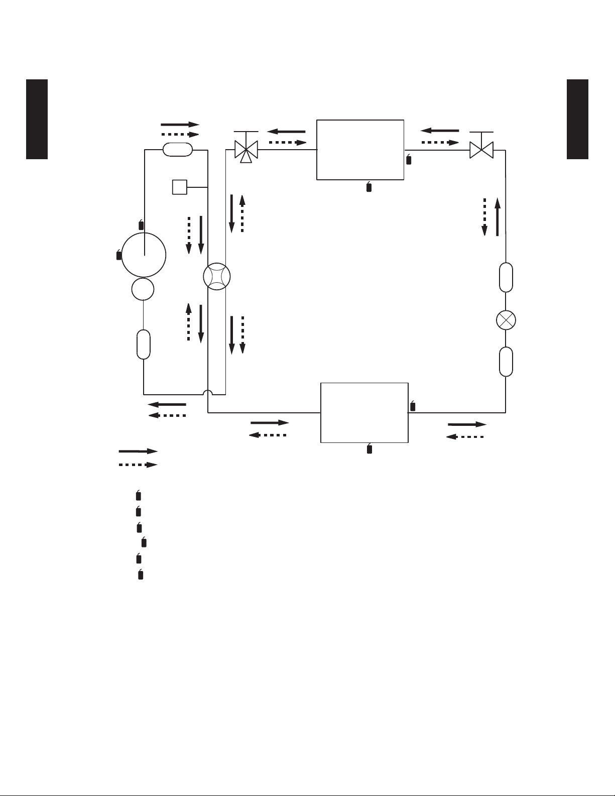
REFRIGERANT CIRCUIT3.
MODEL : AOU18RLB, AOU24RLB
3-Way
valve
Muffler
Muffler
D
Th
Compressor
Heat exchanger
(INDOOR)
R
Th
Th
2-Way
valve
OUTDOOR UNIT
PI
AOU18-36RL
Receiver
Strainer
Th
Th
Th
Th
Th
Heat exchanger
(OUTDOOR)
Cooling
Heating
D
Thermistor (Discharge Temp.)
O
Thermistor (Outdoor Temp.)
HO
Thermistor (Heat Exchanger Out Temp.)
R
Thermistor (Room Temp.)
PI
Thermistor (Pipe Temp.)
Th
Expansion valve
Strainer
HO
Th
O
Refrigerant pipe diameter
Liquid: 1/4” (6.35 mm)
Gas: 1/2” (12.70 mm)
- (02 - 04) -
Page 46
MODEL :AOU30R LXB, AO U36RL XB
OUTDOOR UNIT
AOU18-36RL
Th
3-Way
valve
(Large)
Muffler
Heat exchanger
(INDOOR)
R
Th
Th
3-Way
valve
(Small)
OUTDOOR UNIT
PI
AOU18-36RL
Pressure
switch
D
Th
C
Compressor
4-Way valve
Strainer
Expansion valve
Heat exchanger
Strainer
(OUTDOOR)
Sub-accumulator
Cooling
Heating
C
Th
Th
Th
Th
Th
Th
Thermistor (Compressor Temp.)
D
Thermistor (Discharge Temp.)
O
Thermistor (Outdoor Temp.)
HO
Thermistor (Heat Exchanger Out Temp.)
R
Thermistor (Room Temp.)
PI
Thermistor (Pipe Temp.)
Refrigerant pipe diameter
Liquid: 3/8” (9.52 mm)
Gas: 5/8” (15.88 mm)
Th
HO
Th
O
- (02 - 05) -
Page 47

OUTDOOR UNIT
AOU18-36RL
WIRING DIAGRAMS4.
MODEL : AOU18RLB, AOU24RLB
OUTDOOR UNIT
AOU18-36RL
- (02 - 06) -
Page 48

OUTDOOR UNIT
AOU18-36RL
MODEL :AOU30R LXB, AO U36RL XB
OUTDOOR UNIT
AOU18-36RL
- (02 - 07) -
Page 49

OUTDOOR UNIT
AOU18-36RL
CAPACITY COMPENSATION RATE FOR PIPE LENGTH 5.
AND HEIGHT DIFFERENCE
MODEL : AOU18RLB, AOU24RLB
COOLING
15m 50 ft. - - - 0.951 0.950
10m 33ft. - - 0.979 0.967 0.966
7.5m 25ft. - 0.988 0.983 0.971 0.970
5m 17ft. 0.994 0.992 0.987 0.975 0.974
0m 0ft. 1.002 1.000 0.995 0.983 0.982
-5m -17ft. 1.002 1.000 0.995 0.983 0.982
-7.5m -25ft. - 1.000 0.995 0.983 0.982
-10m -33ft. - - 0.995 0.983 0.982
-15m -50ft. - - - 0.983 0.982
15m 50 ft. - - - 0.994 0.979
10m 33ft. - - 1.012 0.994 0.979
7.5m 25ft. - 1.000 1.012 0.994 0.979
5m 17f t. 0.96 9 1.000 1.012 0.994 0.979
0m 0ft. 0.969 1.000 1.012 0.994 0.979
-5m -17ft. 0.964 0.995 1.007 0.989 0.974
-7.5m -25ft. - 0.993 1.004 0.986 0.972
-10m -33ft. - - 1.0 02 0.98 4 0.969
-15m - 50ft. - - - 0.974 0.959
Height
difference H
Height
difference H
1
Indoor unit is
upper than
outdoor unit.
2
Indoor unit is
under than
outdoor unit
HEATING
1
Indoor unit is
upper than
outdoor unit.
2
Indoor unit is
under than
outdoor unit
Pipe length (m)
5m 7.5m 10m 15m 20m
17ft. 25ft. 33ft. 50ft. 67ft.
Pipe length (m)
5m 7.5m 10m 15m 20m
17ft. 25ft. 33ft. 50ft. 67ft.
OUTDOOR UNIT
AOU18-36RL
Height difference H
Indoor unit
HH
Outdoor unit
Connection pipe
1 Indoor unit is upper than outdoor unit.
- (02 - 08) -
Outdoor unit
Indoor unit
Connection pipe
2 Indoor unit is under than outdoor unit.
Page 50

OUTDOOR UNIT
AOU18-36RL
MODEL :AOU30R LXB, AO U36RL XB
COOLING
30m 99ft. - - - - 0.932 0.929 0.924
Height
difference H
1
Indoor unit is upper
than outdoor unit.
2
Indoor unit is under
than outdoor unit
20m 66ft. - - - 0.945 0.947 0.945 0.940
10m 33ft. - - 0.984 0.961 0.963 0.960 0.956
7.5m 25ft. - 0.988 0.988 0.965 0.967 0.964 0.959
5m 16ft. 0.990 0.992 0.992 0.968 0.971 0.968 0.963
0m 0ft. 0.998 1.000 1.000 0.976 0.979 0.976 0.971
-5m -16ft. 0.998 1.000 1.000 0.976 0.979 0.976 0.971
-7.5m -25ft. - 1.000 1.000 0.976 0.979 0.976 0.971
-10m -33ft. - - 1.000 0.976 0.979 0.976 0.971
-20m -66ft. - - - 0.976 0.979 0.976 0.971
-30m -99ft. - - - - 0.979 0.976 0.971
Pipe length
5m 7.5m 10m 20m 30m 40m 50m
16ft. 25ft. 33ft. 66ft. 99ft. 131ft. 164ft.
OUTDOOR UNIT
AOU18-36RL
Height
difference H
Indoor unit
HEATING
1
Indoor unit is upper
than outdoor unit.
2
Indoor unit is under
than outdoor unit
Pipe length
5m 7.5m 10m 20m 30m 40m 50m
16ft. 25ft. 33ft. 66ft. 99ft. 131ft. 164ft.
30m99ft.----0.816 0.756 0.686
20m 66ft. - - - 0.872 0.816 0.756 0.686
10m 33ft. - - 0.991 0.872 0.816 0.756 0.686
7.5m 25ft. - 1.000 0.991 0.872 0.816 0.756 0.686
5m 16ft. 0.986 1.000 0.991 0.872 0.816 0.756 0.686
0m 0ft. 0.986 1.000 0.991 0.872 0.816 0.756 0.686
-5m -16ft. 0.981 0.995 0.986 0.868 0.812 0.752 0.683
-7.5m -25ft. - 0.993 0.983 0.866 0.810 0.750 0.681
-10m -33ft. - - 0.981 0.864 0.808 0.748 0.679
-20m -66ft. - - - 0.855 0.799 0.740 0.672
-30m-99ft.----0.791 0.733 0.665
Height difference H
Outdoor unit
HH
Outdoor unit
Connection pipe
1 Indoor unit is upper than outdoor unit.
- (02 - 09) -
Indoor unit
Connection pipe
2 Indoor unit is under than outdoor unit.
Page 51

ADDITIONAL CHARGE CALCULATION6.
MODEL : AOU18RLB, AOU24RLB
Refrigerant type R410A
OUTDOOR UNIT
AOU18-36RL
Refrigerant amount
REFRIGERANT CHARGE
Total pipe length
Additional charge
lbs. oz. 3lbs. 1oz.
g1400
ft. 49 or less 66 (MAX)
m15 or less20 (MAX)
oz. 0 3.5
g0 100
MODEL :AOU30R LXB, AO U36RL XB
Refrigerant type R410A
Refrigerant amount
REFRIGERANT CHARGE
Total pipe length
Additional charge
lbs. oz. 4lbs. 10.1oz.
g2100
ft. 66 or less 98 131 164
m20 or less 30 4050 (MAX)
oz. 0 14.1 28.2 42.3
g0 4008001200
0.22oz./f t.
(20g/m)
0.43oz./ft.
(40g/m)
OUTDOOR UNIT
AOU18-36RL
- (02 - 10) -
Page 52

AIR FLOW7.
MODEL :AOU18RLB
Cooling
Air flow
OUTDOOR UNIT
AOU18-36RL
2050 m
569 l/s
1206 CFM
Heating
Air flow
1840 m
511 l/s
1083 CFM
3
/h
3
/h
MODEL : AOU24RLB
Cooling
OUTDOOR UNIT
AOU18-36RL
Air flow
2475 m
688 l/s
1457 CFM
Heating
Air flow
2355 m
654 l/s
1407 CFM
3
/h
3
/h
- (02 - 11) -
Page 53

MODEL :AO U30 RL XB
Cooling
Air flow
OUTDOOR UNIT
AOU18-36RL
3600 m
1000 l/s
2119 CFM
Heating
Air flow
3600 m
1000 l/s
2119 CFM
3
/h
3
/h
MODEL :AO U36 RL XB
Cooling
OUTDOOR UNIT
AOU18-36RL
Air flow
3600 m
1000 l/s
2119 CFM
Heating
Air flow
3600 m
1000 l/s
2119 CFM
3
/h
3
/h
- (02 - 12) -
Page 54

OPERATION NOISE8.
NOISE LEVEL CURVE8-1.
MODEL :AO U18R LB
OUTDOOR UNIT
AOU18-36RL
Cooling
80
70
60
50
40
30
20
Octave band sound pressure level, dB:(0dB=0.0002μbar)
10
0
63 125 250 500 1,000 2,000 4,000 8,000
Octave band center frequency,Hz
NC-65
NC-60
NC-55
NC-50
NC-45
NC-40
NC-35
NC-30
NC-25
NC-20
NC-15
Heating
80
70
60
50
40
30
20
Octave band sound pressure level, dB:(0dB=0.0002μbar)
10
0
63 125 250 500 1,000 2,000 4,000 8,000
Octave band center frequency,Hz
NC-65
NC-60
NC-55
NC-50
NC-45
NC-40
NC-35
NC-30
NC-25
NC-20
NC-15
OUTDOOR UNIT
AOU18-36RL
MODEL : AOU24RLB
Cooling
80
70
60
50
40
30
20
Octave band sound pressure level, dB:(0dB=0.0002μbar)
10
0
63 125 250 500 1,000 2,000 4,000 8,000
Octave band center frequency,Hz
NC-65
NC-60
NC-55
NC-50
NC-45
NC-40
NC-35
NC-30
NC-25
NC-20
NC-15
Heating
80
70
60
50
40
30
20
Octave band sound pressure level, dB:(0dB=0.0002μbar)
10
0
63 125 250 500 1,000 2,000 4,000 8,000
Octave band center frequency,Hz
NC-65
NC-60
NC-55
NC-50
NC-45
NC-40
NC-35
NC-30
NC-25
NC-20
NC-15
- (02 - 13) -
Page 55
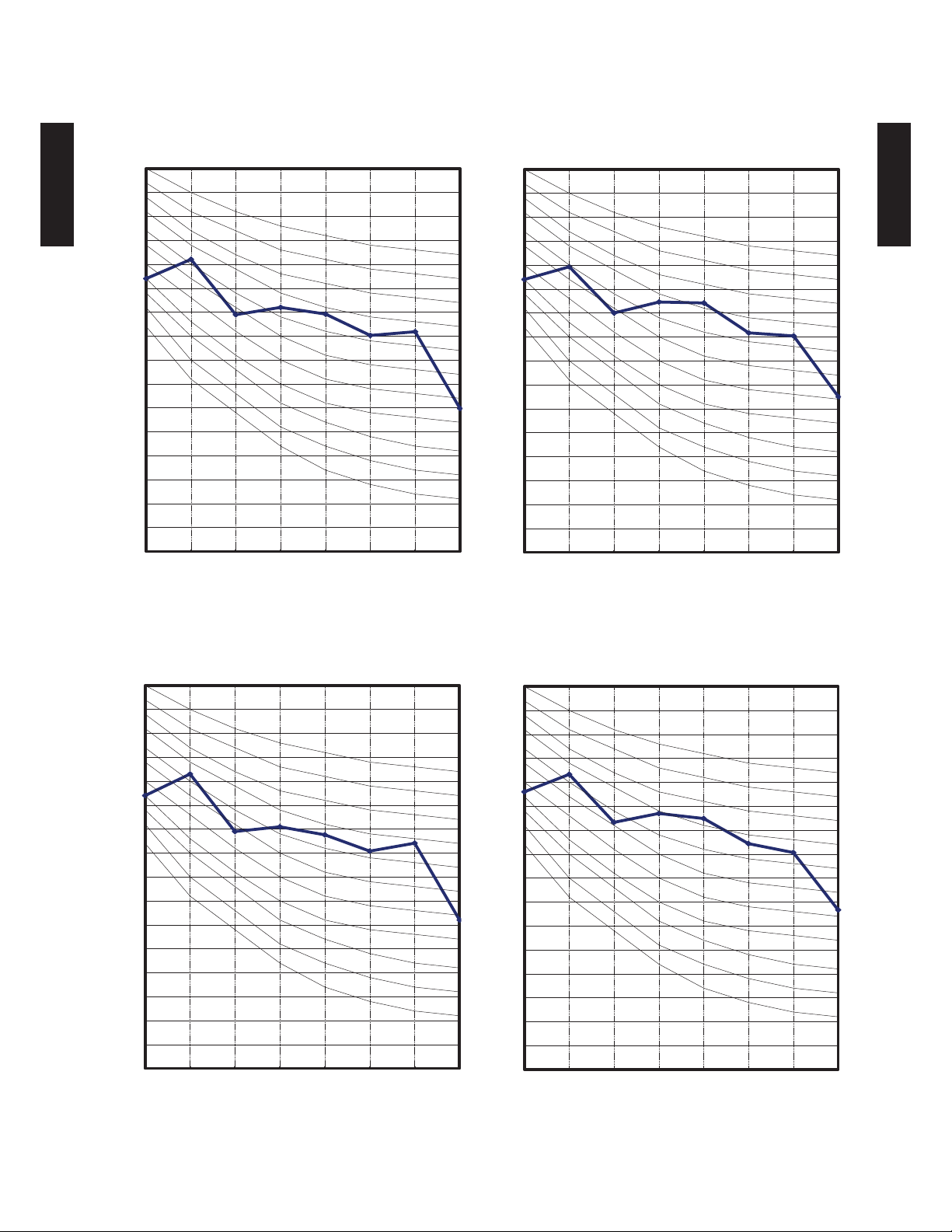
MODEL :AO U30 RL XB
OUTDOOR UNIT
AOU18-36RL
Cooling
80
70
60
50
40
30
20
Octave band sound pressure level, dB:(0dB=0.0002μbar)
10
0
63 125 250 500 1,000 2,000 4,000 8,000
Octave band center frequency,Hz
NC-65
NC-60
NC-55
NC-50
NC-45
NC-40
NC-35
NC-30
NC-25
NC-20
NC-15
Heating
80
70
60
50
40
30
20
Octave band sound pressure level, dB:(0dB=0.0002μbar)
10
0
63 125 250 500 1,000 2,000 4,000 8,000
Octave band center frequency,Hz
NC-65
NC-60
NC-55
NC-50
NC-45
NC-40
NC-35
NC-30
NC-25
NC-20
NC-15
OUTDOOR UNIT
AOU18-36RL
MODEL :AO U36 RL XB
Cooling
80
70
60
50
40
30
20
Octave band sound pressure level, dB:(0dB=0.0002μbar)
10
0
63 125 250 500 1,000 2,000 4,000 8,000
Octave band center frequency,Hz
NC-65
NC-60
NC-55
NC-50
NC-45
NC-40
NC-35
NC-30
NC-25
NC-20
NC-15
Heating
80
70
60
50
40
30
20
Octave band sound pressure level, dB:(0dB=0.0002μbar)
10
0
63 125 250 500 1,000 2,000 4,000 8,000
Octave band center frequency,Hz
NC-65
NC-60
NC-55
NC-50
NC-45
NC-40
NC-35
NC-30
NC-25
NC-20
NC-15
- (02 - 14) -
Page 56

OUTDOOR UNIT
AOU18-36RL
SOUND LEVEL CHECK POINT8-2.
OUTDOOR UNIT
AOU18-36RL
39-3/8in. (1m)
- (02 - 15) -
Page 57

ELECTRIC CHARACTERISTICS9.
OUTDOOR UNIT
AOU18-36RL
Model name AOU18RLB
Power supply
MCA A
Starting current A 6.4
Wiring spec.
*1
*1 : Selected sample based on Japan Electrotechnical Standards and Codes Committee E0005.
*2 : Limit voltage drop to less than 2%. Increase conductor size if voltage drop is 2% or more.
MCA : Min Circuit Amp (Calculation based on UL1995)
MAX. CKT. BKR : Maximum Circuit Breaker
Voltage V 208 / 230 ~
Frequency Hz 60
14.6 17.1 23.3
MAX. CKT. BKR A
Power cable AWG
Connection cable *2 AWG 14
Limited wiring length : ft. (m) 68 (21) 167 (51)
15 20 30
14 12 10
AOU24RLB AOU30RLXB AOU36RLXB
10.5 13.8 17.0
OUTDOOR UNIT
AOU18-36RL
- (02 - 16) -
Page 58

SAFETY DEVICES10.
OUTDOOR UNIT
AOU18-36RL
Circuit protection
Fan motor
protection
High Pressure
Protection
Compressor
protection
Protection form
Current fuse
(NEAR THE TERMINAL)
Current fuse
(MAIN PRINTED CIRCUIT
BOARD)
Thermal protection
program
Pressure Switch
Thermal protection
program
(COMPRESSOR TEMP.)
Thermal protection
program
(DISCHARGE TEMP.)
Thermal protection
program
(OUTDOOR TEMP.)
(Cooling/Dry mode)
Model
AOU18RLB AOU24RLB AOU30RLXB AOU36RLXB
5A 250V
3.15A 250V x 2
OFF : 212±27°F (100±15°C)
18
ON : 203±
°F (95±10°C)
OFF : 302±
ON : 248±
27
°F (150±15°C)
27
°F (120±15°C)
OFF : 4.2±0.1MPa
ON : 3.2±0.15MPa
-
OFF : 230 °F (110 °C)
ON : After 7 minutes
OFF : 5°F (-15°C)
ON : 14°F (-10°C)
OFF : 226°F (108°C)
ON : 176°F (80°C)
OFF : -13°F (-25°C)
ON : -4°F (-20°C)
OUTDOOR UNIT
AOU18-36RL
- (02 - 17) -
 Loading...