

Page 1
OPE RATING M ANUAL
AIR CON DITIONE R
CASSETTE TYPE
Indoor U nit
A UU18R C
OPE R ATING MANUAL
En glis h
A UU24R C
A UU36R C
A UU42R C
Outdoor U nit
A O U18RC
A O U24RC
A O U36RC
A O U42RC
KEEP THIS OPERATION MANUAL
FOR FUTURE REFERENCE.
FUJITSU GENERAL LIMITED
P/N 9368987022
Page 2
CONTENTS
SAFETY PRECAUTIONS ....................................... 1
NAME OF PARTS ................................................... 2
PREPARATION ....................................................... 3
OPERATION ........................................................... 3
TIMER OPERATION (OFF TIMER/ON TIMER) ...... 5
TIMER OPERATION (WEEKLY TIMER) ................. 6
ENERGY SAVE OPERATION ............................... 11
ADJUSTING THE DIRECTION OF
AIR CIRCULATION ............................................... 12
SWING OPERATION ............................................ 12
CLEANING AND CARE ........................................ 13
ERRORS AND SELF DIAGNOSIS ....................... 14
OPERATION DETAILS.......................................... 15
SYSTEM OPERATION ......................................... 16
TROUBLESHOOTING .......................................... 17
SAFETY PRECAUTIONS
● Before using the appliance, read these “PRECAUTIONS” thoroughly and operate in the correct way.
● The instructions in this section all relate to safety; be sure to maintain save operating conditions.
● “DANGER”, “WARNING” and “CAUTION” have the following meanings in these instructions:
DANGER!
WARNING!
CAUTION!
DANGER!
This mark indicates procedures which, if improperly performed, are most likely to
result in the death of or serious injury to the user or service personnel.
This mark indicates procedures which, if improperly performed, might lead to the
death or serious injury of the user.
This mark indicates procedures which, if improperly performed, might possibly result
in personal harm to the user, or damage to property.
● Do not attempt to install this air conditioner by yourself.
● This unit contains no user-serviceable parts. Always consult authorized service per-
sonnel for repairs.
● When moving, consult authorized service personnel for disconnection and installation of the unit.
● Do not become over-exposed to cold air by staying in the direct path of the air flow of
the air conditioner for extended periods of time.
● Do not insert fingers or objects into the outlet port or intake grilles.
● Do not start and stop air conditioner operation by turning off the electrical breaker
and so on.
● In the event of a malfunction (burning smell, etc.), immediately stop operation, turn
off the electrical breaker, and consult authorized service personnel.
En-1
CAUTION!
● Provide occasional ventilation during use.
● Do not direct air flow at fireplaces or heating apparatus.
● Do not climb on, or place objects on, the air conditioner.
● Do not hang objects from the indoor unit.
● Do not set flower vases or water containers on top of air conditioners.
● Do not expose the air conditioner directly to water.
● Do not operate the air conditioner with wet hands.
● Turn off power source when not using the unit for extended periods.
● Always turn off the electrical breaker whenever cleaning the air conditioner or the air
filter.
● Connection valves become hot during Heating; handle with care.
● Check the condition of the installation stand for damage.
● Do not place animals or plants in the direct path of the air flow.
● When restarting after a long period of disuse in the winter, do:
Turn the power switch on at least 12 hours before starting the unit.
● Do not drink the water drained from the air conditioner.
● Do not use in applications involving the storage of foods, plants or animals, precision
equipment, or art works.
● Do not apply any heavy pressure to radiator fins.
● Operate only with air filters installed.
● Do not block or cover the intake grille and outlet port.
● Ensure that any electronic equipment is at least one metre away from each the indoor
and outdoor units.
● Avoid installing the air conditioner near a fireplace or other heating apparatus.
● Whe
● Do not use inflammable gases near the air conditioner.
n installing the indoor and outdoor unit, take precautions to prevent access to infan
ts.
Page 3
NAME OF PARTS
Instructions relating to heating (*) are applicable only to “HEAT & COOL MODEL” (Reverse Cycle).
Fig. 1
Fig. 4
2
13
AM CLOCK
NON STOP
TIMER
H
G
SET TIME TEMP./DAY FAN
MODE
CLOCK ADJUST
FED
I
J K
°F
ZONE
SET
B 8 6
C0A 79
Fig. 2
CONTROL
ENERGY SAVE
DAY OFF
AUTO
MASTER
CONTROL
START/STOP
Electrical Breaker
Fig. 3
This breaker is installed during
the electrical installation.
M
NO PQR
AMPM CLOCK
L
NON STOP
OFFON
TIMER
AMPM
WEEKLY
21
Fig. 5 Display
● For explanatory purposes, the figure showing the remote
controller display shows all possible displays. The actual
display shows only that area that is being adjusted or used.
TIMER
NEXT DAY
OFF
ON
ON
OFF
DAY OFF
DEFROST
S
DAY
AUTO
°F
TEST
T
AUTO
COOL
FAN
HEAT
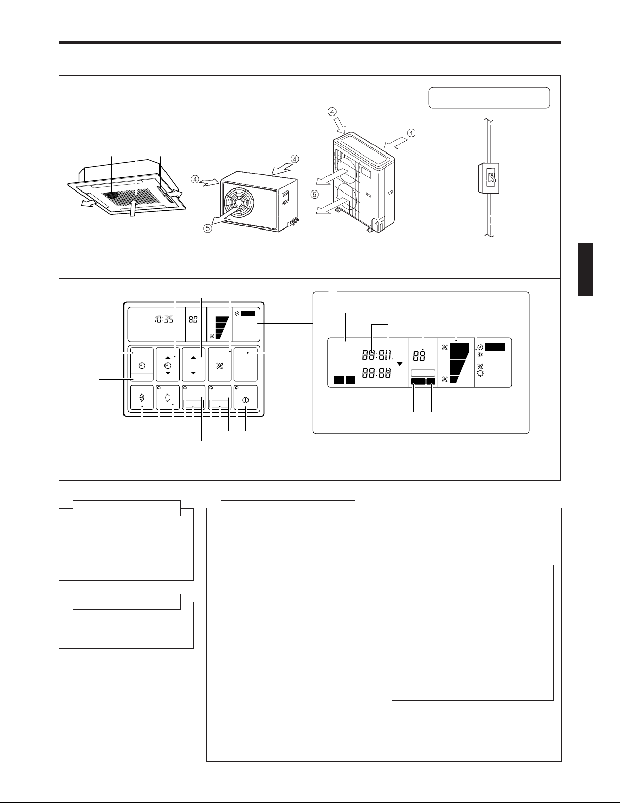
Fig. 1 Indoor Unit
1 Air Filter
2 Air Intake Grille
3 Air Flow Direction
Flaps
Fig. 2 Outdoor Unit
4 Air intake
5 Air outlet
Fig. 4 Remote Controller
6 START/STOP Button
7 Operation Lamp
8 ENERGY SAVE Button
9 DAY OFF Button
0 ENERGY SAVE Lamp
A ZONE Control Button
B SET Button
C ZONE Control Lamp
D AIR FLOW DIRECTION SWING
Button
E AIR FLOW DIRECTION SWING
Lamp
F AIR FLOW DIRECTION SET Button
G CLOCK ADJUST Button
H TIMER MODE Button
I SET TIME Button
J TEMP./DAY Button
K FAN CONTROL Button
L MASTER CONTROL Button
M Remote Controller Display
(Fig. 5)
N Ti mer Mode Display
O Clock Display (CLOCK/TIMER)
P Set Temperature Display
(TEMP.)
Q Fan Speed Display
R Operation Mode Display
S DEFROST Display
T TEST Display
En-2
Page 4
PREPARATION
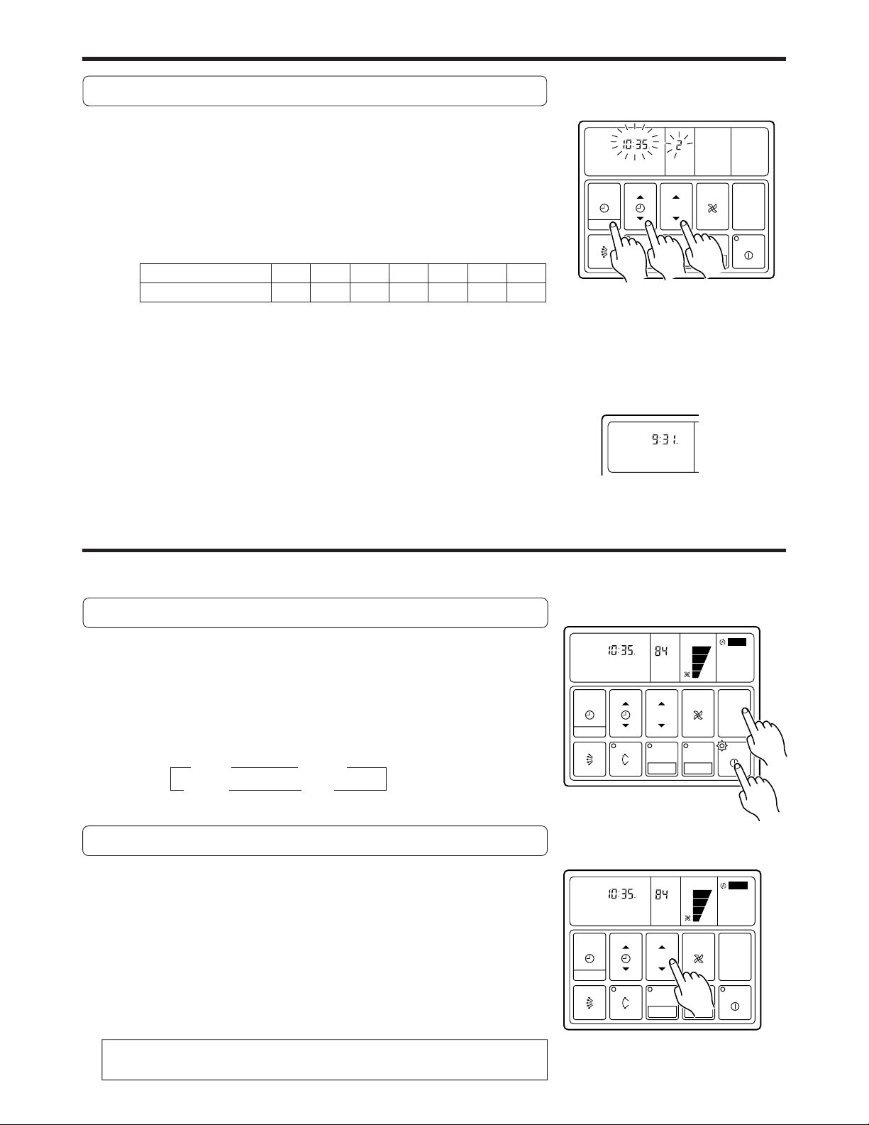
Set the Current Time and Day
Press the CLOCK ADJUST button for more than three
1
seconds.
Press the TEMP./DAY button and set the day.
2
▲: Use to advance the day forward.
▼: Use to turn the day back.
The day is indicated by a code number from 1 to 7, as shown in the table
below. Set to the number that corresponds to the current day.
DAY CODE 1 2 34567
DAY OF THE WEEK MON TUE WED THU FRI SAT SUN
Press the SET TIME button and set the time.
3
▲: Use to advance the time forward.
▼: Use to turn the time back.
(Press once to move the time 1 minute; hold down and the time will move
10 minutes at a time.)
Press the CLOCK ADJUST button again.
4
This registers the new day and time values. The day display goes off, and
the time display stops flashing.
OPERATION
AM CLOCK
DAY
TIMER
SET TIME TEMP./DAY FAN
MODE
CLOCK ADJUST
1
AM CLOCK
3
ZONE
SET
CONTROL
ENERGY SAVE
DAY OFF
2
MASTER
CONTROL
START/STOP
Example: Set the time to 9:31.
Instructions relating to heating (*) are applicable only to “HEAT & COOL MODEL” (Reverse Cycle).
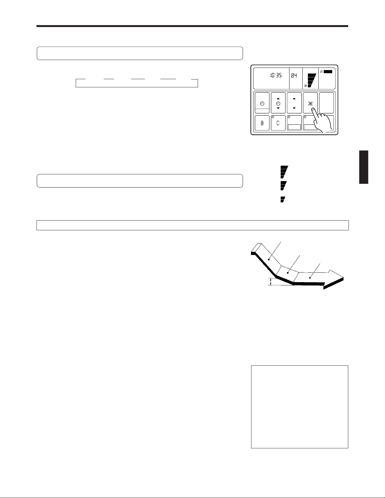
To Select Mode Operation
AM CLOCK
NON STOP
Press the START/STOP button.
1
The unit will start and the remote controller’s operation lamp (green) will
light up.
TIMER
SET TIME TEMP./DAY FAN
MODE
Press the MASTER CONTROL button to select the de-
2
sired mode.
ss
AUTO *HEAT
t
COOL FAN
t
CLOCK ADJUST
Example: When set to AUTO
To Set the Thermostat
Press the TEMP./DAY button to the desired temperature.
▲ : Press to raise the thermostat setting.
▼ : Press to lower the thermostat setting.
●Thermostat setting range:
AUTO ...................................... 64 to 88 °F
* Heating ...................................60 to 88 °F
Cooling/Dry ............................ 64 to 88 °F
The thermostat cannot be used to set room temperature during the FAN mode
(the temperature will not appear on the remote controller’s display).
The thermostat setting should be considered a standard value, and may
differ somewhat from the actual room temperature.
AM CLOCK
NON STOP
TIMER
SET TIME TEMP./DAY FAN
MODE
CLOCK ADJUST
Example: When set to 84 °F
ZONE
SET
ZONE
SET
°F
CONTROL
ENERGY SAVE
DAY OFF
°F
CONTROL
ENERGY SAVE
DAY OFF
AUTO
MASTER
CONTROL
START/STOP
AUTO
MASTER
CONTROL
START/STOP
2
1
En-3
Page 5
OPERATION
Instructions relating to heating(*) are applicable only to “HEAT & COOL MODEL” (Reverse Cycle).
To Set the Fan Speed
Press the FAN CONTROL button to select the fan speed.
s
AUTO HIGH MED LOW
s
When set to AUTO:
* Heating : Fan operates so as to optimally circulate warmed air.
However, the fan will operate at very low speed when the temperature of the air issued from the indoor unit is low.
Cooling : As the room temperature approaches that of the thermostat set-
s
s
AM CLOCK
NON STOP
TIMER
SET TIME TEMP./DAY FAN
MODE
CLOCK ADJUST
ZONE
SET
°F
CONTROL
ENERGY SAVE
DAY OFF
AUTO
MASTER
CONTROL
START/STOP
ting, the fan speed becomes slower.
Fan : The fan alternately turns on and off; when on, the fan runs at the
Example: When set to HIGH
low fan speed.
The fan will operate at a very low setting during Monitor operation.
: HIGH
To Stop Operation
Press the START/STOP button.
The remote controller’s operation lamp (green) will go out.
: MED
: LOW
The display contents disappear and only the current time is displayed.
About Mode Operation
AUTO:
COOLING MODEL
● When the room temperature is 4 °F higher than the set temperature, the mode
will switch between Cooling and Drying.
● During the Drying mode operation, the FAN setting should be switched to LOW
for a gently cooling effect during which the fan may temporarily stop rotating.
● If the mode automatically selected by the unit is not satisfactory, see page 3 for
instructions on changing the mode setting (COOL, FAN).
AUTO (* AUTO CHANGEOVER):
HEAT & COOL MODEL (Reverse cycle)
● When AUTO CHANGEOVER is selected, the air conditioner selects the appropriate operation mode (Cooling or Heating)
according to your room’s present temperature.
● When AUTO CHANGEOVER is first selected, the fan will operate at very low speed for about one minute while the unit
determines the current conditions of the room and accordingly selects the proper operation mode.
● When the air conditioner has adjusted your room’s temperature to near the thermostat setting, it will begin monitor operation. In the monitor operation mode, the fan will operate at low speed. If the room temperature subsequently changes, the
air conditioner will once again select the appropriate operation (Heating, Cooling) to adjust the temperature to the value set
in the thermostat. (The monitor operation range is ±4 °F relative to the thermostat setting.)
● If the mode automatically selected by the unit is not satisfactory, see page 3 for instructions on changing the mode setting
(HEAT, COOL, FAN).
* Heating:
● Use to warm your room.
● When Heating mode is selected, the air conditioner will operate at very low fan
speed for about 3 to 5 minutes, after which it will switch to the selected fan setting. This period of time is provided to allow the indoor unit to warm up before
begin full operation.
● When the room temperature is very low, frost may form on the outside unit, and
its performance may be reduced. In order to remove such frost, the unit will
automatically enter the defrost cycle from time to time. During defrosting (see
page 15), the heating mode will be temporarily interrupted. DEFROST will be
shown on the remote controller display.
Cooling:
● Use to cool your room.
* During Heating mode:
Set the thermostat to a temperature setting that is higher than the current room
temperature. The Heating mode will not
operate if the thermostat is set lower than
the actual room temperature.
During Cooling mode:
Set the thermostat to a temperature setting that is lower than the current room
temperature. The Cooling mode will not
operate if the thermostat is set higher than
the actual room temperature (in Cooling
mode, the fan alone will operate).
Fan:
● Use to circulate the air throughout your room.
Cooling Operation
Dry Operation
Thermostat control
4°F
Setting temperature
En-4
Page 6
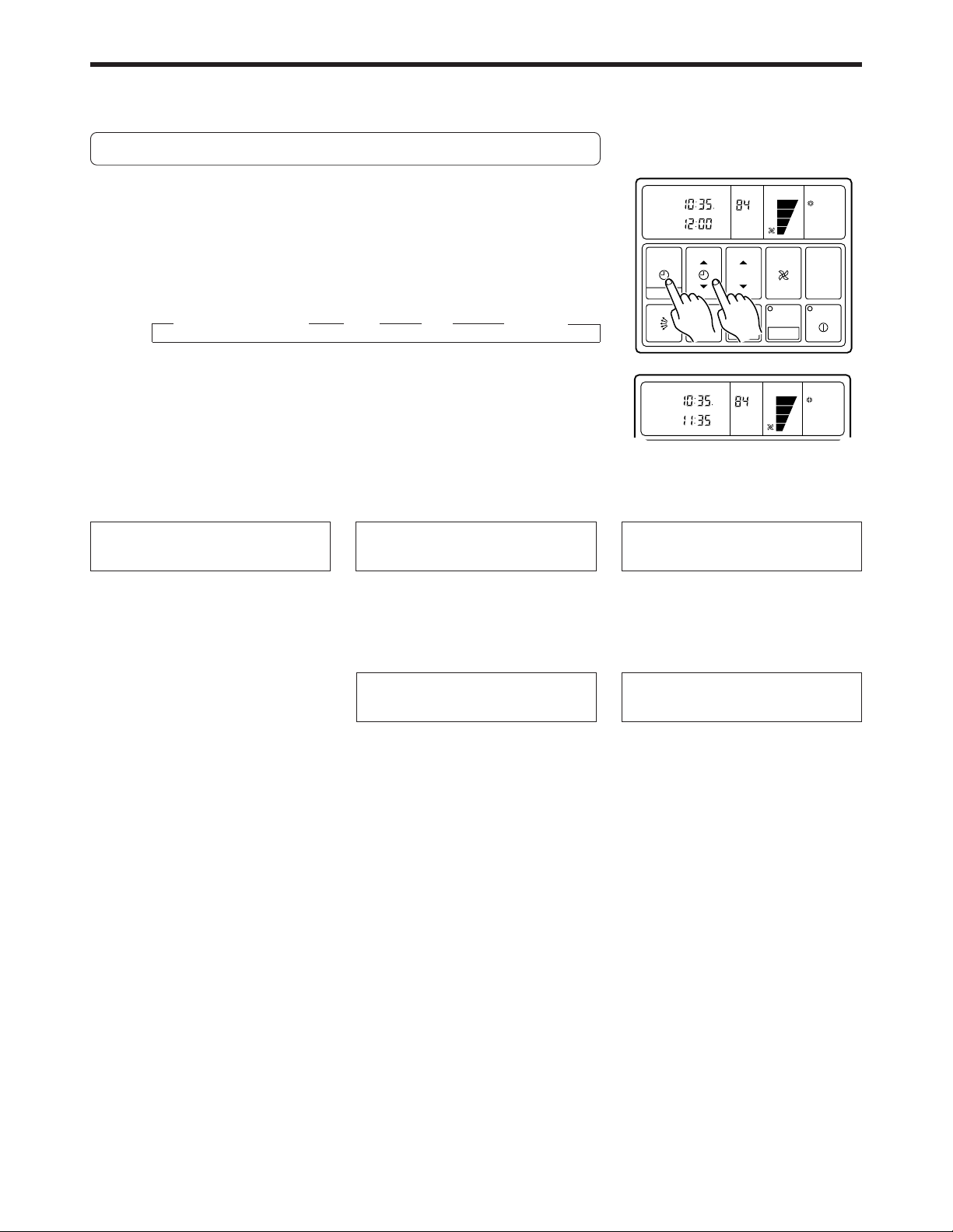
TIMER OPERATION (OFF TIMER/ON TIMER)
Before using the timer function, be sure that the remote controller is set to the correct current time and Day.
Press the START/STOP button; after the unit starts operation perform the following procedure:
OFF Timer / ON Timer
Press the TIMER MODE button and display either OFF
1
Timer or ON Timer.
The timer will start operating. (If you set the ON timer, the air conditioner
will stop operating).
Each time the button is pressed the timer function changes in the following order:
ss
NON STOP (RESET) OFF ON WEEKLY
Press the SET TIME button and set the timer time.
2
▲ : Use to advance the time forward.
▼ : Use to turn the time back.
(Press once to move the time 1 minute; hold down and the time will move
10 minutes at a time.)
To confirm or Change Settings
Before Starting Operation
● To confirm settings
Press the TIMER MODE button once.
(The timer setting information will be
displayed for 15 seconds after the
TIMER MODE button is pressed.)
● To change settings
Confirm the settings as noted above,
then press the SET TIME button and
TIMER MODE button as necessary to
change the desired timer setting.
(The timer settings will be displayed
for 15 seconds after the button is
pressed.)
● After confirming or changing the settings, press the START/STOP button
to start operation.
s s
To Change the Timer Setting
During Operation
Operate as noted in step 2.
To Change the Timer Mode
During Operation
Press the TIMER MODE button and set
the unit to the desired mode.
AM CLOCK
OFF
TIMER
CLOCK ADJUST
TIMER
AM
TIMER
SET TIME TEMP./DAY FAN
MODE
1
AM CLOCK
OFF
TIMER
Example: Setting the OFF TIMER
CLOCK ADJUST
To Cancel the Timer Mode
TIMER
PM
TIMER
SET TIME TEMP./DAY FAN
MODE
to 11:35 p.m.
OFF
OFF
ZONE
2
SET
ZONE
SET
°F
CONTROL
ENERGY SAVE
°F
CONTROL
ENERGY SAVE
DAY OFF
DAY OFF
COOL
MASTER
CONTROL
START/STOP
COOL
MASTER
CONTROL
START/STOP
During Timer Operation
Press the TIMER MODE button and set
the display to “NON STOP” (the unit will
switch to non-stop operation).
To Stop Operation During
Use of Timer Mode
Press the START/STOP button.
En-5
Page 7

TIMER OPERATION (WEEKLY TIMER)
Use the weekly timer to set operating times for each day of the week.
Weekly Timer Features
● Set different operating times for each day of the week.
● Set one or two operating spans (one or two ON times and one or two OFF times) per day.
● Set time to a resolution of 5 minutes.
● OFF time can be carried over to the subsequent day.
● Use the “DAY OFF” setting to cancel operation for any day of the coming week (one-time cancellation).
Setting Up the Weekly Timer Operation
Press the START/STOP button to stop the air conditioner, and then proceed as follows.
Press the TIMER MODE button so that “WEEKLY” ap-
1
pears on the display.
The display now shows the current day (by DAY CODE), the first ON and
OFF times for the day (the “WEEKLY 1” times), the fan speed, and the
operating mode.
The top time value gives the ON time, and the bottom value gives the
OFF time.
If either time is not set, the corresponding time display is blank “
Press the TEMP./DAY button to select the day that you
2
want to set up.
▲ : Use to advance the day forward.
▼ : Use to turn the day back.
WEEKLY
1
TIMER
MODE
CLOCK ADJUST
”.
ON
TIMER
OFF
SET TIME TEMP./DAY FAN
ZONE
1
SET
DAY
CONTROL
START/STOP
ENERGY SAVE
2
DAY OFF
3
COOL
MASTER
CONTROL
DAY CODE 1 2 3 4 5 6 7
DAY OF THE WEEK MON TUE WED THU FRI SAT SUN
Hold the SET button down for 3 seconds.
3
The “WEEKLY 1” ON time starts flashing, and the fan speed and operating mode displays go off.
Press the SET TIME button to set the day’s first ON
4
time.
▲ : Use to advance the time forward.
▼ : Use to turn the time back.
(Press once to move the time 5 minute; hold down and the time will move
10 minutes at a time.)
Press the SET button.
5
This registers the first ON time setting for the selected day.
The ON time display stops flashing, and the “WEEKLY 1” OFF time starts
flashing.
AM
WEEKLY
1
TIMER
SET TIME TEMP./DAY FAN
MODE
CLOCK ADJUST
TIMER
OFF
ON
DAY
CONTROL
MASTER
CONTROL
ZONE
SET
4
ENERGY SAVE
DAY OFF
START/STOP
5
En-6
Page 8

TIMER OPERATION (WEEKLY TIMER)
Press the SET TIME button to set the day’s first OFF
6
time.
The earliest OFF time you can set is 5 minutes after the ON time. The
latest OFF time is 11:55 p.m. on the subsequent day.
Press the SET button.
7
This registers the first OFF time for the day, completing the “WEEKLY 1”
settings for that day.
The display switches to “WEEKLY 2”, and the day’s second ON time begins flashing.
Repeat the operations described in Steps 4 to 7 to set
8
the second ON and OFF times for the day (the “WEEKLY
2” times).
When you press the SET button after setting the “WEEKLY 2” OFF time,
the system registers the “WEEKLY 2” settings for the day and returns you
to the “WEEKLY 1” ON time setup process. (The first ON setting reappears and begins flashing.)
You can review your settings by pressing the SET button. Each press
moves you to the next setting, as follows.
ss
WEEKLY 1 WEEKLY 1 WEEKLY 2 WEEKLY 2
s
s
ON OFF ON OFF
Press the TEMP./DAY button to select another day for
9
setup. The repeat steps 4 to 8 above to set the ON and
OFF times for that day.
AM
ON
TIMER
PM
WEEKLY
1
TIMER
SET TIME TEMP./DAY FAN
MODE
CLOCK ADJUST
OFF
ZONE
SET
DAY
6
CONTROL
ENERGY SAVE
DAY OFF
MASTER
CONTROL
START/STOP
7
If the timer is not set, press the SET button with the time display blank “
and perform next operation.
”,
When you have finished setting all of the times, hold
10
down the SET button for 3 seconds.
The WEEKLY display flashes for 3 seconds while the new WEEKLY TIMER
settings are registered, and then the clock display reappears.
NOTES:
(1) If no time values are flashing, the clock display will automatically reappear after 15 seconds if no buttons are pressed.
(2) A flashing time value indicates that the system is in time-setting mode. To return to the clock display you must hold
down the SET button for 3 seconds.
(3) You do not need to set values for both WEEKLY 1 and WEEKLY 2. If you wish, you can set values only for WEEKLY 1
or only for WEEKLY 2.
(4) The allowable range for the day’s time settings is shown below.
Cannot set
ON OFF ON OFF
Previous day’s WEEKLY
settings
5 min.
12:00 a.m. 12:00 a.m.
Available range Cannot set
5 min.
Next day’s WEEKLY
(5) If you set the OFF time to occur on the day following the ON time, the NEXT DAY caption appears on the display.
PM
ON
TIMER
WEEKLY
2
PM
NEXT DAY
OFF
DAY
AM CLOCK
TIMER
SET TIME TEMP./DAY FAN
settings
En-7
Page 9

TIMER
MODE
SET
ZONE
START/STOP
CLOCK ADJUST
SET TIME TEMP./DAY FAN
CONTROL
MASTER
CONTROL
DAY OFF
ENERGY SAVE
°F
AM CLOCK
PM
TIMER
WEEKLY
OFF
1
COOL
1
2
Starting Weekly Timer Operation
Press the TIMER MODE button so that “WEEKLY” ap-
1
pears on the display.
Press the START/STOP button to start operation.
2
(This step is not necessary if the air conditioner is already running.)
Weekly timer operation starts, and the operation lamp comes on.
(If the current time is between the first or second ON and OFF time settings for the current day, the air conditioner will start. Otherwise the air
conditioner will remain off.)
The day display is replaced by the temperature display.
The upper time display now shows the current time, and the lower time
display shows the next scheduled ON or OFF time.
To Stop Weekly Timer Operation
● To stop weekly timer while leaving the air conditioner running:
Press the TIMER MODE button to select NONSTOP, OFF
TIMER, or ON TIMER.
● To stop weekly timer operation and the air conditioner also:
Press the START/STOP button.
Reviewing the Time Settings
Press the START/STOP button to stop the air conditioner, and
then proceed as follows.
1 Press the TIMER MODE button so that “WEEKLY” appears
on the display.
2 Press the TEMP./DAY button to select the day that you want
to check.
3 Press the SET TIME button (▲ or ▼) to switch between the
“WEEKLY 1” or “WEEKLY 2” time displays.
Cancelling Selected Time Settings
Press the START/STOP button to stop the air conditioner, and then proceed as follows.
Carry out steps 1 to 3 of the “Setting Up the Weekly
1
Timer Operation” procedure to select the day you want
to edit.
Press the SET button to select the ON time that you
2
want to cancel.
Be sure to select an ON time (the upper time display).
Hold down the ▼ side of the SET TIME button until the
3
time display becomes blank “
”.
PM
WEEKLY
1
TIMER
SET TIME TEMP./DAY FAN
MODE
CLOCK ADJUST
TIMER
3
OFF
ON
DAY
CONTROL
MASTER
CONTROL
ZONE
SET
ENERGY SAVE
DAY OFF
START/STOP
2
Press the SET button.
4
The first OFF time setting (“WEEKLY 1” OFF time) is deleted and replaced
by a flashing blank pattern “
5
Press the SET button again.
This completes deletion of the “WEEKLY 1” ON/OFF settings.
The second ON time setting (“WEEKLY 2” ON time) appears and flashes.
If you wish to delete other time settings, repeat steps 2 through 5.
”.
Once the setting has been canceled, hold down the
6
SET button for 3 seconds.
The WEEKLY display flashes briefly, and then the clock display appears.
Example: Clearing the “WEEKLY 1” ON/
OFF times for day 4 (Thursday)
WEEKLY
1
WEEKLY
2
TIMER
PM
TIMER
PM
OFF
OFF
DAY
ON
DAY
ON
En-8
Page 10

TIMER OPERATION (WEEKLY TIMER)
To Change Selected Time Settings
Press the START/STOP button to stop the air conditioner, and then proceed as follows.
Carry out steps 1 to 3 of the “Setting Up the Weekly
1
Timer Operation” procedure to select the day you want
to edit.
Press the SET button to select the time that you want
2
to change.
The selected setting flashes on the display. Each press moves you to the
next setting for the selected day, as follows.
sss
WEEKLY 1 WEEKLY 1 WEEKLY 2 WEEKLY 2
s
ON OFF ON OFF
Press the SET TIME button to change the time setting.
3
Press the SET button.
4
The new setting overwrites the previous setting.
Once the setting has been canceled, hold down the SET
5
button for 3 seconds.
The WEEKLY display flashes briefly, and then the clock display appears.
PM
ON
TIMER
PM
WEEKLY
2
TIMER
SET TIME TEMP./DAY FAN
MODE
CLOCK ADJUST
OFF
ZONE
SET
DAY
CONTROL
ENERGY SAVE
DAY OFF
MASTER
CONTROL
START/STOP
2
Example: Changing the “WEEKLY 2”
ON setting for day 5 (Friday)
from 2:00p.m. to 3:30p.m.
PM
PM
WEEKLY
21
TIMER
SET TIME TEMP./DAY FAN
MODE
CLOCK ADJUST
TIMER
3
ON
OFF
ZONE
SET
DAY
AUTO
DEFROST TEST
CONTROL
START/STOP
ENERGY SAVE
DAY OFF
AUTO
MASTER
CONTROL
NOTES:
In the following cases, cancel the set time prior to making the required amendments.
(1) If you want to change the ON time to a time that is later than the currently set OFF time.
ON OFF
WEEKLY 1
Change
ON
WEEKLY 1
OFF
(2) If the change would cause a temporary overlap between the first and second ON/OFF time spans.
Change
ON OFF
WEEKLY 1
ON
WEEKLY 1 WEEKLY 2
ON OFF
WEEKLY 2
Temporary overlap
OFF
ON OFF
4
Time
Time
Time
Time
En-9
Page 11

About the DAY OFF
● Use the DAY OFF setting to switch off timed operation for a selected day in the coming week.
● This is a temporary, one-time setting. The DAY OFF setting is automatically cleared as soon as the specified day passes.
Using the DAY OFF Setting
Press the START/STOP button to stop the air conditioner, and then proceed as follows.
Carry out steps 1 to 2 of the “Setting Up the Weekly
1
Timer Operation” procedure to select the day that you
want to set as the DAY OFF.
Press the DAY OFF button.
2
The DAY OFF setting is registered, and the DAY OFF caption appears on
PM
TIMER
PM
WEEKLY
1
TIMER
SET TIME TEMP./DAY FAN
MODE
CLOCK ADJUST
OFF
ON
DAY
DAY OFF
CONTROL
ZONE
ENERGY SAVE
SET
DAY OFF
the display.
● To cancel the DAY OFF setting:
You can cancel the setting by pressing the DAY OFF button again.
Example: To switch off timed operation
for day 2 (Tuesday)
NOTES:
(1) The DAY OFF setting is only available for days for which weekly time settings already exist.
(2) You can make this setting for any of the next seven days (counting from the current day).
(3) The DAY OFF setting is effective over the range illustrated below. The Weekly setting for which an ON time has been
set is eligible for the day in which the DAY OFF has been set.
Effective range of DAY OFF setting
ON OFF
ON OFF
COOL
MASTER
CONTROL
START/STOP
2
WEEKLY setting for preceding
day
Preceding day DAY OFF day
(4) The display on the clock’s lower line will usually be “
AM CLOCK
WEEKLY
TIMER
SET TIME TEMP./DAY FAN
MODE
TIMER
°F
DAY OFF
CONTROL
COOL
12:00 a.m.
” for the DAY OFF set day during Weekly operations.
Precautions during setup
Setup is not possible in the following cases, so amend the time.
● If you set an ON time while leaving the OFF time setting blank:
Nothing will happen when you press the SET button.
To proceed, press the SET TIME button and enter an appropriate setting.
● When an attempt is made to set only the OFF time.
Nothing will happen when you press the SET TIME button.
Press the SET button and amend the entry for the ON time.
● ON and OFF times cannot be set to the same value.
● The OFF time cannot be set earlier than the ON time.
● The WEEKLY 2 settings cannot be set earlier than the WEEKLY 1 settings.
● The WEEKLY 1 and WEEKLY 2 time spans cannot overlap.
WEEKLY setting
12:00 a.m.
Next day
En-10
Page 12

ENERGY SAVE OPERATION
Instructions relating to heating (*) are applicable only to “HEAT & COOL MODEL” (Reverse Cycle).
To Use the ENERGY SAVE
Press the ENERGY SAVE button.
The unit will run in the ENERGY SAVE mode.
NON STOP
AM CLOCK
°F
AUTO
The ENERGY SAVE lamp (green) will light.
TIMER
SET TIME TEMP./DAY FAN
To Stop the ENERGY SAVE
Press the ENERGY SAVE button one more time.
The ENERGY SAVE mode will be turned off.
MODE
CLOCK ADJUST
ZONE
SET
CONTROL
ENERGY SAVE
DAY OFF
MASTER
CONTROL
START/STOP
The ENERGY SAVE lamp goes off, and the unit will return to the former operating conditions.
About the ENERGY SAVE
● The energy conservation mode (ENERGY SAVE) raises the set temperature slightly in the cooling mode and lowers the set
temperature in the heating mode, using a computer program to economically control the operation of the unit.
● If you press the ENERGY SAVE button while the air conditioner is on, it will change to the conservation mode. If you press
the ENERGY SAVE button while the unit is in the timer mode (ON timer, WEEKLY timer), the unit will go into the conservation mode when the unit starts with the timer.
● If you turn off the air conditioner while in the conservation mode, the mode will be shut off.
● The temperature set on the remote controller will not change if the energy save mode is used.
■ * When Heating
After the ENERGY SAVE button is pressed, the set temperature will be lowered about 2 °F every 30 minutes. When it
has lowered a total of 4 °F, then it will hold that temperature.
■ When Cooling
After the ENERGY SAVE button is pressed, the set temperature will be raised about 1 °F every 30 minutes. When it has
gone up a total of 2 °F, then it will hold that temperature.
2°F
30 min.
4°F
▲ Set to the ENERGY SAVE mode.
▼ Set to the ENERGY SAVE mode.
30 min.
2°F
1°F
En-11
Page 13

ADJUSTING THE DIRECTION OF AIR CIRCULATION
21
DEFROST TEST
21
DEFROST TEST
Instructions relating to heating (*) are applicable only to “HEAT & COOL MODEL” (Reverse Cycle).
Begin air conditioner operation before performing this procedure.
Vertical Air Flow Direction Adjustment
Press the AIR FLOW DIRECTION SET button.
Each time the button is pressed, the air flow direction range will change as follows:
Fig. 6
2 3 4
1
The remote controller’s display does not change.
● Use the air flow direction adjustments within the ranges shown above.
● The air flow direction is set automatically as shown, in accordance with the
type of operation selected.
During Cooling mode : Horizontal flow 1
* During Heating mode : Downward flow 4
● During AUTO mode operation, for the first minute after beginning operation,
air flow will be horizontal 1; the air flow direction cannot be adjusted during
this period.
1
2
3
4
TIMER
SET TIME TEMP./DAY FAN
MODE
CLOCK ADJUST
ZONE
SET
CONTROL
START/STOP
ENERGY SAVE
DAY OFF
MASTER
CONTROL
● Always use the remote controller’s AIR
FLOW DIRECTION SET button to adjust the UP/DOWN air flow direction
flaps. Attempting to move them manually could result in improper operation;
in this case, stop operation and restart.
The flaps should begin to operate
properly again.
● When used in a room with infants, children, elderly or sick persons, the air
flow direction and room temperature
should be considered carefully when
making settings.
SWING OPERATION
Begin air conditioner operation before performing this procedure.
To Select SWING Operation
Press the AIR FLOW DIRECTION SWING button.
The AIR FLOW DIRECTION SWING lamp (orange) will light.
In this mode, the UP/DOWN air flow direction flaps will swing automatically to
direct the air flow both up and down.
To Stop SWING Operation
Press the AIR FLOW DIRECTION SWING button once again.
The AIR FLOW DIRECTION SWING lamp will go out.
Air flow direction will return to the setting before swing was begun.
About Swing Operation
● The range of swing is relative to the currently set air flow
direction.
Air flow direction set
1
2, 3
4
Range of swing
1 to 3
2 to 4
1 to 4 (All range)
Air flow direction range (see Fig. 6)
● If the swing range is not as desired, use the remote controller’s AIR FLOW DIRECTION SET button to change the
range of swing.
● The SWING operation may stop temporarily when the air
conditioner’s fan is not operating, or when operating at
very low speeds.
TIMER
SET TIME TEMP./DAY FAN
MODE
CLOCK ADJUST
ZONE
SET
CONTROL
ENERGY SAVE
DAY OFF
MASTER
CONTROL
START/STOP
En-12
Page 14

CLEANING AND CARE
CAUTION!
● Before cleaning the unit, be sure to stop the unit and disconnect the power supply.
● Turn off the electrical breaker.
● A fan operates at high speed inside the unit, and personal injury could result.
Cleaning the Air Filter
1. Push the intake grille pushbuttons (two
places).
2. Open the intake grille.
OPEN
PUSH
3. Hold down the hook at A and pull the filter out.
A
● When reinstalling the filter, be sure that the hooks at A
and B engage correctly into place.
B
4. Clean the air filters.
Remove the dust from the air filters by vacuuming or
washing them. After washing, allow the air filters to dry
thoroughly in an area protected from sunlight.
● Dust can be cleaned from the air filter either with a vacuum
cleaner, or by washing the filter in a solution of mild detergent and warm water. If you wash the filter, be sure to
allow it to dry thoroughly in a shady place before reinstalling.
● If dirt is allowed to accumulate on the air filter, air flow
will be reduced, lowering operating efficiency and increasing noise.
● During periods of normal use, the air filters should be
cleaned every two months.
Filter
B
A
Intake grille
● When used for extended periods, the unit may accumulate dirt inside, reducing its performance. We recommend that the
unit be inspected regularly, in addition to your own cleaning and care. For more information, consult authorized service
personnel.
● When cleaning the unit’s body, do not use water hotter than 100 °F, harsh abrasive cleansers, or volatile agents like
benzene or thinner.
● Do not expose the unit body to liquid insecticides or hairsprays.
● If the unit will not be operated for a period of one month or more, be sure to allow the inner parts of the unit to dry
thoroughly, in advance, by operating the unit in fan mode for half a day.
En-13
Page 15

ERRORS AND SELF DIAGNOSIS
Error Code
TIMER
SET TIME TEMP./DAY FAN
MODE
CLOCK ADJUST
ZONE
SET
CONTROL
START/STOP
ENERGY SAVE
DAY OFF
MASTER
CONTROL
If there is a problem with the air conditioner, it will stop running and “E: EE” will be displayed instead of the clock.
(1) If the operation lamp is on then press the START/
STOP button to turn it off.
(2) Press the SET TIME (▼) and the TEMP./DAY (▼)
buttons at the same time for more than three seconds
to start the self diagnosis check.
An error code will be displayed in the clock display area.
(3) Press the SET TIME (▼) and the TEMP./DAY (▼) buttons
again for more than three seconds to end the self diagnosis check.
Error Code
Error contents
Communication error
t
(indoor unit remote controller)
s
Communication error
t
(indoor unit outdoor unit)
s
Room temperature sensor open
Room temperature sensor shortcircuited
Indoor heat exchanger temperature
sensor open
Indoor heat exchanger temperature
sensor shortcircuited
Outdoor heat exchanger temperature
sensor open
Outdoor heat exchanger temperature
sensor shortcircuited
Power source connection error
Float switch operated
Outdoor temperature sensor open
Outdoor temperature sensor
shortcircuited
Discharge pipe temperature sensor open
Discharge pipe temperature sensor
shortcircuited
Outdoor high pressure abnormal
Discharge pipe temperature abnormal
Model abnormal
Indoor fan abnormal
Outdoor signal abnormal
Outdoor EEPROM abnormal
En-14
Page 16

OPERATION DETAILS
Instructions relating to heating(*) are applicable only to “HEAT & COOL MODEL” (Reverse Cycle).
Please read and understand the following details regarding this air conditioner.
Operation and Performance
* Heating Performance
● This air conditioner uses a heat pump which absorbs heat
from outside air and brings it indoors. As a result, its heating performance is reduced as the temperature of outside air drops. If you find that insufficient room heat is
produced, we recommend that you use the air conditioner
together with other heating appliances.
● Heat-pump type air conditioners use warm-air
recirculation to warm your entire room. As a result, some
time will be required after starting operation until your
entire room becomes warm.
*
When Indoor and Outdoor Temperatures are High
When both indoor and outdoor temperatures are high during use of the heating mode, the outdoor unit’s fan may stop
at times.
AUTO Restart
In Event of Power Interruption
● Should the power supply to the air conditioner be interrupted by a power failure, the air conditioner will restart
automatically in the previously selected mode once the
power is restored.
*
Microcomputer-controlled Automatic Defrosting
When the outside temperature is low and the humidity high,
frost will collect on the outside unit, reducing heater efficiency. When this happens, the computer will automatically
start the defrost cycle. During the defrost cycle, the indoor
fan will shutdown and DEFROST will be displayed on the
remote controller. It will take anywhere from 4 to 15 minutes before the air conditioner starts up again.
Low Ambient Cooling
When the outdoor temperature drops, the outdoor unit’s fans
may switch to Low Speed, or one of the fans may stop intermittently.
● Use of other electrical appliances (electric shaver, etc.) or
nearby use of a wireless radio transmitter may cause the
air conditioner to malfunction. In this event, temporarily
turn off the circuit breaker turn it on again and then use
the remote controller to resume operation.
Temperature and Humidity Range
Cooling/Dry Mode
Outdoor temperature
COOLING MODEL
HEAT &
COOL MODEL
(Reverse Cycle)
Indoor temperature
Indoor humidity
● If the air conditioner is used under higher temperature conditioner than those listed, the built-in protection circuit may
operate to prevent internal circuit damage. Also, during Cooling and Dry modes, if the unit is used under conditions of
lower temperature than those listed above, the heat-exchanger may freeze, leading to water leakage and other damage.
● Do not use this unit for any purposes other than the Cooling, (*)Heating, Dehumidifying, and air-circulation of rooms in
ordinary dwellings.
AUU18RC
AUU24RC
AUU36RC
AUU42RC
About 32 to 115 °F
About 32 to 115 °F
About 65 to 90 °F
About 80 % or less
If the unit is used for long periods under high-humidity
conditions, condensation
may form on the surface of
the indoor unit, and drip onto
the floor or other objects underneath.
*Heating Mode
—
About 32 to 75 °F
About 17 to 75 °F
About 86 °F or less
—
En-15
Page 17

SYSTEM OPERATION
<Control Several Units with just one Remote Controller>
One remote controller can control up to 16 air conditioners.
All the air conditioners can be operated with the same setting.
Remote
controller
To Use the ZONE CONTROL
When the ZONE control button is pressed while multiple air conditioners
are being centralized controlled, only the preset air conditioners stop.
Press the ZONE control button.
Preset units will stop.
The ZONE lamp (green) will light.
To Stop the ZONE CONTROL
Press the ZONE control button one more time.
Those units that were stopped will start again.
The ZONE lamp will go out.
Outdoor
unit
Indoor unit
Unit No.1
Unit No.2 Unit No.16
AM CLOCK
NON STOP
TIMER
SET TIME TEMP./DAY FAN
MODE
CLOCK ADJUST
ZONE
SET
°F
CONTROL
ENERGY SAVE
DAY OFF
AUTO
MASTER
CONTROL
START/STOP
En-16
Page 18

TROUBLESHOOTING
Instructions relating to heating (*) are applicable only to “HEAT & COOL MODEL” (Reverse Cycle).
WARNING!
Before requesting service, perform the following checks:
In the event of a malfunction (burning smell, etc.), immediately stop operation, turn off the electrical breaker, and consult authorized service personnel.
Merely turning off the unit’s power switch will not completely disconnect the unit from the power
source. Always be sure to turn off the electrical breaker to ensure that power is completely off.
NORMAL
FUNCTION
Symptom
Doesn’t operate immediately:
Noise is heard:
Smells:
Mist or steam are
emitted:
Problem
● If the unit is stopped and then immediately started again, the compressor will not operate for about 3 minutes, in order to prevent
fuse blowouts.
● Whenever the electrical breaker is turned off then on again, the
protection circuit will operate for about 3 minutes, preventing unit
operation during that period.
● During operation and immediately after stopping the unit, the
sound of water flowing in the air conditioner’s piping may be
heard. Also, noise may be particularly noticeable for about 2 to 3
minutes after starting operation (sound of coolant flowing).
● During operation, a slight squeaking sound may be heard. This is
the result of minute expansion and contraction of the panel due
to temperature changes.
*● During Heating operation, a sizzling sound may be heard occa-
sional. This sound is produced by the Automatic Defrosting operation.
● Some smell may be emitted from the indoor unit. This smell is
the result of room smells (furniture, tobacco, etc.) which have
been taken into the air conditioner.
● During Cooling, a thin mist may be seen emitted from the indoor
unit. This results from the sudden Cooling of room air by the air
emitted from the air conditioner, resulting in condensation and
misting.
See Page
—
—
15
—
—
Air flow is weak or stops:
Water is produced from
the outdoor unit:
*● During Heating operation, the outdoor unit’s fan may stop, and
steam may be seen rising from the unit. This is due to Automatic
Defrosting operation.
*● When Heating operation is started, fan speed is temporarily very
low, to allow internal parts to warm up.
*● During Heating operation, if the room temperature rises above
the thermostat setting, the outdoor unit will stop, and the indoor
unit will operate at very low fan speed. If you wish to warm the
room further, set the thermostat for a higher setting.
*● During Heating operation, the unit will temporarily stop opera-
tion (between 2 and 16 minutes) as the Automatic Defrosting mode
operates. During Automatic Defrosting operation, DEFROST will
be shown on the remote controller display.
● The fan may operate at very low speed when the unit is monitoring the room’s temperature.
● In the monitor AUTO operation, the fan will operate at very low
speed.
*● During Heating operation, water may be produced from the out-
door unit due to Automatic Defrosting operation.
15
—
15
4
4
15
En-17
Page 19

Instructions relating to heating (*) are applicable only to “HEAT & COOL MODEL” (Reverse Cycle).
Symptom
CHECK ONCE
MORE
If the problem persists after performing these checks, or if you notice burning smells, stop operation immediately, turn off the
electrical breaker, and consult with authorized service personnel.
Doesn’t operate at all:
Poor Cooling (or *Heating)
performance:
● Has there been a power failure?
● Has a fuse blown out, or a circuit breaker been tripped?
● Is the timer operating?
● Is the air filter dirty?
● Are the air conditioner’s intake grille or outlet port blocked?
● Did you adjust the room temperature settings (thermostat) cor-
rectly?
● Is there a window or door open?
● In the case of Cooling operation, is a window allowing bright sun-
light to enter? (Close the curtains.)
● In the case of Cooling operation, are there heating apparatus and
computers inside the room, or are there too many people in the
room?
Items to check
See Page
—
5
—
En-18
 Loading...