

Page 1

AIR CONDITIONER
Wall Mounted type
DESIGN & TECHNICAL MANUAL
INDOOR
OUTDOOR
ASU30CLX1
ASU36CLX1
AOU30CLX1
AOU36CLX1
Page 2

1. INDOOR UNIT
WALL MOUNTED TYPE :
ASU30CLX1
ASU36CLX1
DTR_AS048E_02
2011.02.10
Page 3

CONTENTS
WALL MOUNTED TYPE
ASU30-36CLX1
WALL MOUNTED TYPE
ASU30-36CLX1
1. INDOOR UNIT
1. FEATURE
.................................................................................................................. 01 - 01
2. WIRELESS REMOTE CONTROLLER
3. SPECIFICATIONS
4. DIMENSIONS
5. WIRING DIAGRAMS
6. CAPACITY TABLE
6-1. COOLING CAPACITY
7. FAN PERFORMANCE
7-1. AIR VELOCITY DISTRIBUTION
7-2. AIR FLOW
.......................................................................................................... 01 - 12
8. OPERATION NOISE
8-1. NOISE LEVEL CURVE
.............................................................................................. 01 - 05
........................................................................................................ 01 - 06
........................................................................................ 01 - 07
............................................................................................ 01 - 08
...................................................................................... 01 - 08
.................................................................................... 01 - 10
..................................................................... 01 - 10
......................................................................................... 01 - 13
.................................................................................... 01 - 13
............................................... 01 - 03
8-2. SOUND LEVEL CHECK POINT
..................................................................... 01 - 14
9. ELECTRIC CHARACTERISTICS
10. SAFETY DEVICES
11. EXTERNAL INPUT & OUTPUT
11-1. EXTERNAL INPUT
11-2. EXTERNAL OUTPUT
12. FUNCTION SETTING
12-1. INDOOR UNIT
13. OPTIONAL PARTS
............................................................................................ 01 - 16
............................................................... 01 - 17
........................................................................................... 01 - 17
....................................................................................... 01 - 18
...................................................................................... 01 - 19
.................................................................................................. 01 - 19
........................................................................................... 01 - 21
........................................................... 01 - 15
Page 4

FEATURE1.
Front view
b
a
c
Large air flow and quiet
operation by new air
flow path
High efficiency
layout
P
P
More compact compared with conventional model
AM technology makes a compressor more powerful.P
PAM control
b
DC
twin rotary compressor
c
a
DC
fan motor
DC fan motor
MODEL
WALL MOUNTED TYPE
ASU30-36CLX1
ASU30CLX1 / AOU30CLX1
WALL MOUNTED TYPE
ASU30-36CLX1
ASU36CLX1 / AOU36CLX1
FEATURES
High energy performance
z
MODEL
AS U3 0CL X1 AS U36CL X1
Seasonal Energy Efciency Ratio (SEER)
Energy Efcient Ratio (EER) 9.5 8.5
MEASUREMENT CONDITIONS
ANSI/ASHR AE STANDARD 37-1988
ALL DC
z
BTU/hW
16.5 15.5
Super quiet
z
Air ow mode can be set in 4 steps and more detailed air ow setting is possible.
Easy maintenance
z
Easy maintenance and always clean. Troublesome maintenance has been made easy.
Since the front panel is easy to remove, maintenance is also easy.
- (01 - 01) -
Page 5

Power diffuser
Power diffuser
Outside air conditions: 95oF 40%
( F)
Operation contents: Cooling,
Set temperature (Min set temp)
65
o
F, Air flow Hi,
o
6559 61 63
7
3
0
10 20 30 40
(ft.)
(ft.)
Vertical flap : Upward
Horizontal flap : Center
Organic coating fin used
heat exchanger
Pre Filter
Antibacterial deodorizing
pre-filter with special
ceramic powder
Ion Deodorization Filter
Apple-catechin Filter
Applecatechin Filter
Long-life Ion
Deodorization Filter
Blue fin heat exchanger
Cobalt Blue protection
Standard chromate protection
Aluminium base material
Hydrophilic coating
z
WALL MOUNTED TYPE
ASU30-36CLX1
“Healthy horizontal air ow” does not blow
cool air directly at the occupants in the room.
Low outdoor air temperature cooling correspondence
z
WALL MOUNTED TYPE
ASU30-36CLX1
Corresponds to cooling operation at 14°F (-10°C) outdoor air temperature
Corresponds to maximum 164 feet (50m) long piping
z
Air conditioner lter features
z
Blue n heat exchanger
z
Corrosion-resistance of the heat exchanger even in coastal areas has been improved by blue n
treatment of the outdoor unit heat exchanger.
- (01 - 02) -
Page 6

WIRELESS REMOTE CONTROLLER2.
60min.
2°F (1°C)
4°F (2°C)
Timer setting
A B C D
A B
C
D
Mixed-up
I.U. I.U. I.U. I.U.
I.U. I.U. I.U. I.U.
After code change
FEATURES
Four kinds of timer setup
WALL MOUNTED TYPE
ASU30-36CLX1
Built-in timers
z
Select from four different timer programs (On / Off / Program / Sleep).
Program timer
z
The program timer operates the on and off timer once within a 24 hour period.
Sleep timer
z
The sleep timer function automatically corrects the temperature thermostat setting according to
the timer setting to prevent excessive cooling while sleeping.
¾
(On / Off / Program / Sleep) are possible.
Four kinds of timers. Easy operation.
¾
Easy to change transmission code (4 patterns) by button operation.
¾
WALL MOUNTED TYPE
ASU30-36CLX1
Cooling operation/dry operation
When the sleep timer is set, the set temperature
automatically rises 2°F (1°C) every hour. The set
temperature can rise up to a maximum of 4°F (2°C).
Switching remote controller signal code
z
Code selector switch eliminates unit
•
being wrongly switched.
(Up to 4 codes can be set.)
*I.U.=Indoor unit
- (01 - 03) -
Page 7

16
17
18
20
22
21
23
19
15
2
8
1
14
4
9
12
10
11
13
7
6
5
3
FUNCTIONS
WALL MOUNTED TYPE
ASU30-36CLX1
1
SLEEP button
2
MASTER CONTROL button
3
SET TEMP. button ( / )
4
Signal transmitter
5
TIMER MODE button
6
TIMER SET (+ / -) button
7
FAN CONTROL button
8
START/STOP button
9
SET button (Vertical)
10
SET button (Horizontal)
11
SWING button
12
RESET button
13
TEST RUN button
• This button is used when installing the air conditioner, and
should not be used under normal conditions, as it will cause the
indoor unit’s thermostat function to operate incorrectly.
• If this button is pressed during normal operation, the indoor
unit will switch to test operation mode, and the Indoor Unit’s
OPERATION Indicator Lamp and TIMER Indicator Lamp will
begin to ash simultaneously.
• To stop the test operation mode, press the START/STOP button
to stop the air conditioner.
WALL MOUNTED TYPE
ASU30-36CLX1
14
CLOCK ADJUST button
15
Remote controller display
16
Transmit indicator
17
Clock display
18
Operating mode display
19
Display panel
Functions will be dif ferent due to type of indoor unit.
For details, please see operation manual.
To facilitate explanation, the accompanying
Timer mode display
20
Fan speed display
21
Temperature set display
22
Sleep display
23
Swing display
illustration has been drawn to show all possible
indicators; in actual operation, however,
the display will only show those indicators
appropriate to the current operation.
SPECIFICATION
SIZE [ H x W x D ]
WEIGHT [ w/o batteries ] oz. (g) 3 (85)
in. (mm) 6-11/16 x 2-7/32 x 3/4 (170 x 56 x 19)
ACCESSORY Holder
- (01 - 04) -
Page 8

SPECIFICATIONS3.
Typ e
WALL MOUNTED TYPE
ASU30-36CLX1
Model name AS U30CL X1 AS U36CL X1
Power sour ce 208/230V ~ 60 Hz
Available voltage r ange 187-253V ~ 60Hz
Cooling
Capacity
Heating
Input power
Current
EER Cooling
COP Heating
SEER Cooling BTU/hW 16.5 15.5
HSPF Heating BTU/hW - SENSIBLE CAPACIT Y Cooling kW 6.25 6.39
POWER FACTOR
Moisture removal pints/ h (l/h) 9.7(4.6) 10 .1(4 .8)
Fan
Sound pressure level
Heat exchanger ty pe
Enclosure
Dimensions
( H×W×D)
Weight
Connection pipe
Operat ion range
Remote controll er type Wireless
Drain pipe
Cooling
Heating
Cooling
Heating
Airow
rate
Type × Q'ty Cross ow fan x 1
Motor output W 42 65
Net
Gross
Net
Gross 40 (18 )
Size
Method Flare
Material PVC
Size
Rated
Min-Max
Rated
Min-Max
Rated
Max 3.87 4.10
Rated - Max - Rated
Max 17.0 18.0
Rated - Max - -
Cooling
Heating - -
High
Cooling
Heating
Cooling
Heating
Dimensions
(H × W × D)
Fin pitch FPI Main:21, Sub:18
Rows x Stages Main:2×18, Sub:1×4
Pipe type Copper
Fin type Aluminium
Material Polystyrene
Color
Liquid
Gas Ø5/8 (Ø15.8 8 )
Cooling
Heating °F (°C) - -
Med 530 (900) 5 30 (90 0)
Low 435 (740) 435 (740)
Quiet 365 (620) 365 (620)
High - Med - -
Low - -
Quiet - -
High
Med 42 42
Low 37 37
Quiet 33 33
High - Med - -
Low - -
Quiet - -
kW 9.00 9.70
BTU/h 30,800 33,000
kW 2.90 - 9.50 2.90 - 10.00
BTU/h 9900 - 32400 990 0 - 34100
kW - -
BTU/h - -
kW - -
BTU/h - -
kW
A
kW/kW 2.78 2.50
BTU/hW 9.5 8.5
kW/kW - -
BTU/hW - -
%
CFM
3
(m
/h)
dB(A)
in. (mm)
mm 320×998×228
inch 12-5/8×39-1/4×9
mm 319×109 0×429
inch 12-3/5×42-15/16×16-7/8
lbs .(k g)
in. (mm)
°F (°C) 64 to 90 (18 to 32)
%RH 80 or less
mm
(Reference in.)
3.24 3.88
14.2 17. 0
99 99
659 (1,120) 694 (1,180)
49 50
Main:15-7/8 x 33 -3/4 x 1-1/16 (378×832×26.6)
Sub: 3- 5/16 x 33-3/4 x 17/32 (84×8 32×13.3)
Approximate Color of MUN SELL N9.25/
WALL MOU NTED
INVERTER COOLING ONLY
White
31 (14 )
Ø3/8 (Ø9. 52)
Outer diameter: 28 (1-3/32)
Inner dia meter: 16 (5/ 8) .
WALL MOUNTED TYPE
ASU30-36CLX1
Note :
Specications are based on the following conditions.
Cooling : Indoor temperature of 80°F (26.67 °C)DB / 67°F (19.44 °C)WB, and outdoor temperature of 95°F (35 °C)DB / 75°F (23.9 °C)WB.
Pipe length : 24ft.7in. (7.5 m), Height difference : 0 m.(Outdoor unit - Indoor unit)
- (01 - 05) -
Page 9

DIMENSIONS4.
2-15/32 (63) or more
3-5/32 (80) or more
2-3/32 (53) or more
2-1/16 (52) or more
3-5/32 (80) or more
Outline of unit
4-23/32 (120) or more
59-1/16 (1,500) or more
70-7/8 (1,800) or more
39-9/32 (998)
8-31/32
(228)
12-19/32 (320)
MODEL : ASU30CLX1, ASU36CLX1
WALL MOUNTED TYPE
ASU30-36CLX1
INSTALLATION PLACE
Unit : in. (mm)
Unit : in. (mm)
WALL MOUNTED TYPE
ASU30-36CLX1
- (01 - 06) -
Page 10

WIRING DIAGRAMS5.
MODEL : ASU30CLX1, ASU36CLX1
WALL MOUNTED TYPE
ASU30-36CLX1
WALL MOUNTED TYPE
ASU30-36CLX1
- (01 - 07) -
Page 11

CAPACITY TABLE6.
COOLING CAPACITY6-1.
WALL MOUNTED TYPE
ASU30-36CLX1
MODEL : ASU30CLX1
AFR 659
WALL MOUNTED TYPE
ASU30-36CLX1
°FDB 64 70 75 80 85 90
°FWB 54 60 63 67 71 73
°FDB TC SHC IP TC SHC IP TC SHC IP TC SHC IP TC SHC IP TC SHC IP
14 26.31 18.98 0.82 29.31 19.09 0.83 32.30 20.83 0.84 33.30 22.49 0.85 35.30 22.40 0.86 37.30 23.86 0.87
32 26.28 19.70 1.08 29.27 19.81 1.10 32.27 21.61 1.11 33.27 23.34 1.12 35.26 23.24 1.13 37.26 24.76 1.14
41 26.26 18.96 1.20 29.26 19.07 1.22 32.25 20.80 1.24 33.25 22.46 1.25 35.24 22.37 1.26 37.24 23.83 1.27
50 26.20 19.33 1.36 29.19 19.44 1.38 32.17 21.21 1.40 33.17 22.90 1.41 35.16 22.81 1.42 37.15 24.30 1.44
59 26.02 19.23 1.50 28.99 19.34 1.53 31.95 21.10 1.55 32.94 22.78 1.56 34.92 22.69 1.57 36.89 24.17 1.59
67 25.03 18.67 1.76 27.88 18.78 1.78 30.73 20.48 1.81 31.68 22.12 1.82 33.58 22.03 1.84 35.48 23.47 1.86
77 26.98 19.77 2.52 30.05 19.88 2.55 33.12 21.69 2.59 34.15 23.42 2.61 36.20 23.33 2.63 38.25 24.85 2.66
87 25.67 19.03 2.81 28.60 19.14 2.86 31.52 20.88 2.90 32.50 22.55 2.91 34.45 22.46 2.94 36.40 23.92 2.97
Outdoor temperature
95 24.26 18.24 3.13 27.02 18.35 3.18 29.79 20.01 3.22 30.70 21.35 3.24 32.55 21.53 3.27 34.39 22.93 3.30
104 22.68 17.37 3.43 25.26 17.47 3.49 27.84 19.06 3.54 28.70 20.58 3.56 30.43 20.50 3.59 32.15 21.84 3.63
115 17.27 14.47 2.87 19.23 14.56 2.91 21.20 15.88 2.96 21.86 17.15 2.97 23.17 17.08 3.00 24.48 18.20 3.03
AFR: Ai r ow rate (CFM )
TC: Total capac ity (kBT U)
SHC: Sen sible hea t capaci ty (kBTU )
IP: Input P ower (kW)
AFR 18.7
°CDB 17.8 21.1 23.9 26.7 29.4 32.2
°CWB 12.2 15.6 17.7 19.4 21.7 22.8
°CDB TC SHC IP TC SHC IP TC SHC IP TC SHC IP TC SHC IP TC SHC IP
-10.0 7.71 5.56 0.82 8.59 5.60 0.83 9.47 6.10 0.84 9.76 6.59 0.85 10.35 6.56 0.86 10.93 6.99 0.87
0.0 7.70 5.77 1.08 8.58 5.81 1.10 9.46 6.33 1.11 9.75 6.84 1.12 10.33 6.81 1.13 10.92 7.26 1.14
5.0 7.70 5.56 1.20 8.57 5.59 1.22 9.45 6.10 1.24 9.74 6.58 1.25 10.33 6.56 1.26 10.91 6.98 1.27
10.0 7.68 5.66 1.36 8.55 5.70 1.38 9.43 6.22 1.40 9.72 6.71 1.41 10.30 6.69 1.42 10.89 7.12 1.44
15.0 7.63 5.64 1.50 8.50 5.67 1.53 9.36 6.18 1.55 9.65 6.68 1.56 10.23 6.65 1.57 10.81 7.08 1.59
19.4 7.33 5.47 1.76 8.17 5.50 1.78 9.01 6.00 1.81 9.28 6.48 1.82 9.84 6.46 1.84 10.40 6.88 1.86
25.0 7.91 5.79 2.52 8.81 5.83 2.55 9.71 6.36 2.59 10.01 6.86 2.61 10.61 6.84 2.63 11.21 7.28 2.66
30.6 7.52 5.58 2.81 8.38 5.61 2.86 9.24 6.12 2.90 9.52 6.61 2.91 10.10 6.58 2.94 10.67 7.01 2.97
Outdoor temperature
35.0 7.11 5.35 3.13 7.92 5.38 3.18 8.73 5.87 3.22 9.00 6.26 3.24 9.54 6.31 3.27 10.08 6.72 3.30
40.0 6.65 5.09 3.43 7.40 5.12 3.49 8.16 5.59 3.54 8.41 6.03 3.56 8.92 6.01 3.59 9.42 6.40 3.63
46.1 5.06 4.24 2.87 5.64 4.27 2.91 6.21 4.65 2.96 6.41 5.03 2.97 6.79 5.01 3.00 7.17 5.33 3.03
Indoor temperature
Indoor temperature
AFR : Air ow rate (m3/min)
TC : Total capac ity (kW )
SHC : Sens ible hea t capaci ty (kW)
IP: Input P ower (kW)
- (01 - 08) -
Page 12

WALL MOUNTED TYPE
ASU30-36CLX1
MODEL : ASU36CLX1
AFR 695
WALL MOUNTED TYPE
ASU30-36CLX1
°FDB 64 70 75 80 85 90
°FWB 54 60 63 67 71 73
°FDB TC SHC IP TC SHC IP TC SHC IP TC SHC IP TC SHC IP TC SHC IP
14 27.62 19.93 1.01 30.77 20.05 1.03 33.92 21.87 1.04 34.97 23.61 1.05 37.07 23.52 1.06 39.16 25.05 1.07
32 27.59 20.68 1.33 30.74 20.80 1.35 33.88 22.69 1.37 34.93 24.50 1.38 37.02 24.41 1.39 39.12 26.00 1.41
41 27.58 19.90 1.48 30.72 20.02 1.51 33.86 21.84 1.53 34.91 23.58 1.54 37.00 23.49 1.55 39.10 25.02 1.57
50 27.51 20.29 1.68 30.65 20.41 1.70 33.78 22.27 1.73 34.83 24.05 1.74 36.92 23.95 1.76 39.01 25.51 1.77
59 27.32 20.19 1.85 30.44 20.31 1.88 33.55 22.15 1.91 34.59 23.92 1.92 36.66 23.82 1.94 38.74 25.38 1.96
67 26.28 19.60 2.16 29.27 19.72 2.20 32.26 21.51 2.23 33.26 23.23 2.24 35.26 23.13 2.27 37.25 24.64 2.29
77 28.33 20.75 3.10 31.55 20.88 3.15 34.78 22.77 3.20 35.86 24.59 3.21 38.01 24.49 3.25 40.16 26.09 3.28
87 26.96 19.98 3.47 30.03 20.10 3.52 33.10 21.92 3.58 34.12 23.68 3.60 36.17 23.58 3.63 38.22 25.12 3.67
Outdoor temperature
95 25.47 19.15 3.86 28.37 19.27 3.92 31.28 21.02 3.98 33.00 21.80 3.88 34.18 22.60 4.04 36.11 24.08 4.08
104 23.81 18.24 4.23 26.52 18.35 4.30 29.24 20.01 4.37 30.14 21.61 4.39 31.95 21.52 4.43 33.76 22.93 4.48
115 18.13 15.20 3.54 20.19 15.29 3.59 22.26 16.67 3.65 22.95 18.01 3.67 24.33 17.94 3.70 25.70 19.11 3.74
AFR: Ai r ow rate (CFM )
TC: Total capac ity (kBT U)
SHC: Sen sible hea t capaci ty (kBTU )
IP: Input P ower (kW)
AFR 19.7
°CDB 17.8 21.1 23.9 26.7 29.4 32.2
°CWB 12.2 15.6 17.7 19.4 21.7 22.8
°CDB TC SHC IP TC SHC IP TC SHC IP TC SHC IP TC SHC IP TC SHC IP
-10.0 8.10 5.84 1.01 9.02 5.88 1.03 9.94 6.41 1.04 10.25 6.92 1.05 10.86 6.89 1.06 11.48 7.34 1.07
0.0 8.09 6.06 1.33 9.01 6.10 1.35 9.93 6.65 1.37 10.24 7.18 1.38 10.85 7.15 1.39 11.47 7.62 1.41
5.0 8.08 5.83 1.48 9.00 5.87 1.51 9.92 6.40 1.53 10.23 6.91 1.54 10.84 6.88 1.55 11.46 7.33 1.57
10.0 8.06 5.95 1.68 8.98 5.98 1.70 9.90 6.53 1.73 10.21 7.05 1.74 10.82 7.02 1.76 11.43 7.48 1.77
15.0 8.01 5.92 1.85 8.92 5.95 1.88 9.83 6.49 1.91 10.14 7.01 1.92 10.75 6.98 1.94 11.35 7.44 1.96
19.4 7.70 5.75 2.16 8.58 5.78 2.20 9.46 6.30 2.23 9.75 6.81 2.24 10.33 6.78 2.27 10.92 7.22 2.29
25.0 8.30 6.08 3.10 9.25 6.12 3.15 10.19 6.67 3.20 10.51 7.21 3.21 11.14 7.18 3.25 11.77 7.65 3.28
30.6 7.90 5.86 3.47 8.80 5.89 3.52 9.70 6.43 3.58 10.00 6.94 3.60 10.60 6.91 3.63 11.20 7.36 3.67
Outdoor temperature
35.0 7.47 5.61 3.86 8.32 5.65 3.92 9.17 6.16 3.98 9.70 6.39 3.88 10.02 6.62 4.04 10.58 7.06 4.08
40.0 6.98 5.35 4.23 7.77 5.38 4.30 8.57 5.87 4.37 8.83 6.33 4.39 9.36 6.31 4.43 9.89 6.72 4.48
46.1 5.31 4.45 3.54 5.92 4.48 3.59 6.52 4.89 3.65 6.73 5.28 3.67 7.13 5.26 3.70 7.53 5.60 3.74
Indoor temperature
Indoor temperature
AFR : Air ow rate (m3/min)
TC : Total capac ity (kW )
SHC : Sens ible hea t capaci ty (kW)
IP: Input P ower (kW)
- (01 - 09) -
Page 13

FAN PERFORMANCE7.
7(2) 3(1)
2(0.5)
7(2)
3(1)
2(0.5)
2(0.5)
2(0.5)
3(1)
3(1)
7(2)
7(2)
7(2)
3(1)
2(0.5)
AIR VELOCITY DISTRIBUTION7-1.
WALL MOUNTED TYPE
ASU30-36CLX1
MODEL : ASU30CLX1
(m)
(ft)
2
7
1
3
0
0
1
3
2
7
0 1 2 3 4 5 6 7 8
7 14 20 27
(m)
(ft)
10
3
7
2
Unit : ft/s (m/s)
Unit : ft/s (m/s)
TOP VIEW
Vertic al ap : Up
Horizo ntal ap : C enter
(m)
(ft)
Note:
Fan speed : HIGH
Operation mode : FAN
WALL MOUNTED TYPE
ASU30-36CLX1
3
1
0
0
0 1 2 3 4 5 6 7 8
7 14 20 27
(ft)
(m)
3
10
2
7
1
3
0
0
1
3
2
7
3
10
0 1 2 3 4 5 6 7 8
7 14 20 27
(ft)
10
(m)
3
Unit : ft/s (m/s)
Unit : ft/s (m/s)
SIDE VI EW
Vertic al ap : Up
Horizo ntal ap : C enter
(m)
(ft)
TOP VIEW
Vertic al ap : Up
Horizo ntal ap : R ight & Lef t
(m)
(ft)
7
3
0
2
1
0
0 1 2 3 4 5 6 7 8
7 14 20 27
- (01 - 10) -
SIDE VI EW
Vertic al ap : Dow n
Horizo ntal ap : C enter
(m)
(ft)
Page 14

Note:
7(2)
3(1)
2(0.5)
7(2)
3(1)
2(0.5)
2(0.5)
2(0.5)
3(1)
3(1)
7(2)
7(2)
7(2)
3(1)
2(0.5)
WALL MOUNTED TYPE
ASU30-36CLX1
MODEL : ASU36CLX1
Fan speed : High
Operation mode : FAN
WALL MOUNTED TYPE
ASU30-36CLX1
(m)
(ft)
2
7
1
3
0
0
1
3
2
7
0 1 2 3 4 5 6 7 8
7 14 20 27
(m)
(ft)
10
3
7
2
3
1
0
0
0 1 2 3 4 5 6 7 8
7 14 20 27
(ft)
(m)
3
10
Unit : ft/s (m/s)
Unit : ft/s (m/s)
Unit : ft/s (m/s)
TOP VIEW
Vertic al ap : Up
Horizo ntal ap : C enter
(m)
(ft)
SIDE VI EW
Vertic al ap : Up
Horizo ntal ap : C enter
(m)
(ft)
2
7
1
3
0
0
1
3
2
7
3
10
0 1 2 3 4 5 6 7 8
(ft)
(m)
10
3
7
2
3
1
0
0
0 1 2 3 4 5 6 7 8
7 14 20 27
7 14 20 27
Unit : ft/s (m/s)
TOP VIEW
Vertic al ap : Up
Horizo ntal ap : R ight & Lef t
(m)
(ft)
SIDE VI EW
Vertic al ap : Dow n
Horizo ntal ap : C enter
(m)
(ft)
- (01 - 11) -
Page 15
AIR FLOW7-2.
WALL MOUNTED TYPE
ASU30-36CLX1
MODEL : ASU30CLX1
Cooling
z
Number of
Fan speed
rotations
Air ow
(r.p.m.)
112 0 m
3
/h
WALL MOUNTED TYPE
ASU30-36CLX1
HIGH 1480
MED 1220
LOW 1020
QUIET 900
MODEL : ASU36CLX1
Cooling
z
Number of
Fan speed
rotations
(r.p.m.)
311 l/s
659 CFM
900 m
3
250 l/s
530 CFM
740 m
3
206 l/s
435 CFM
620 m
3
172 l/s
365 CFM
Air ow
118 0 m
3
/h
/h
/h
/h
HIGH 1560
MED 1220
LOW 1020
QUIET 900
328 l/s
694 CFM
3
900 m
/h
250 l/s
530 CFM
3
740 m
/h
206 l/s
435 CFM
3
620 m
/h
172 l/s
365 CFM
- (01 - 12) -
Page 16
OPERATION NOISE8.
High
Quiet
High
Quiet
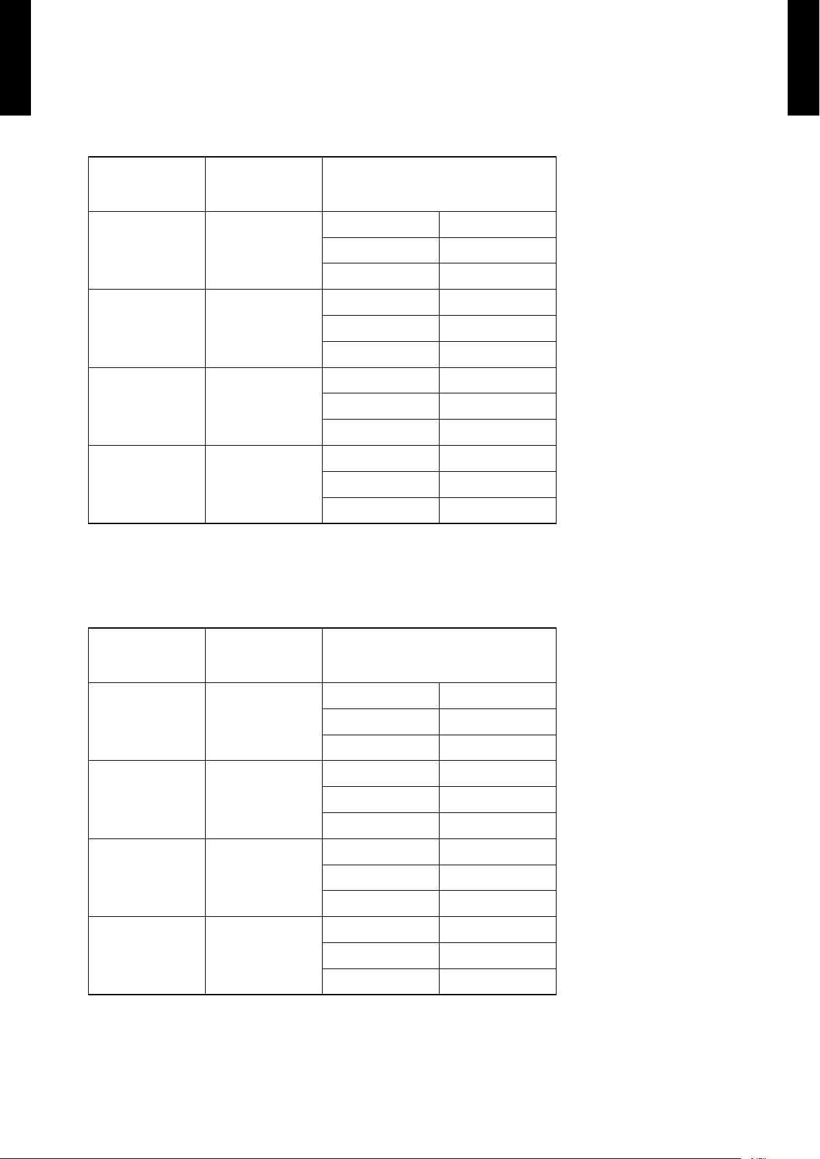
NOISE LEVEL CURVE8-1.
WALL MOUNTED TYPE
ASU30-36CLX1
MODEL : ASU30CLX1
Cooling
z
80
70
60
50
40
30
20
Octave band sound pressure level, dB:(0 dB= 0.00 02µbar)
10
NC-65
NC-60
NC-55
NC-50
NC-45
NC-40
NC-35
NC-30
NC-25
NC-20
NC -15
WALL MOUNTED TYPE
ASU30-36CLX1
0
63 125 250 500 1,000 2 ,000 4,000 8,0 00
Octave band center frequ ency,Hz
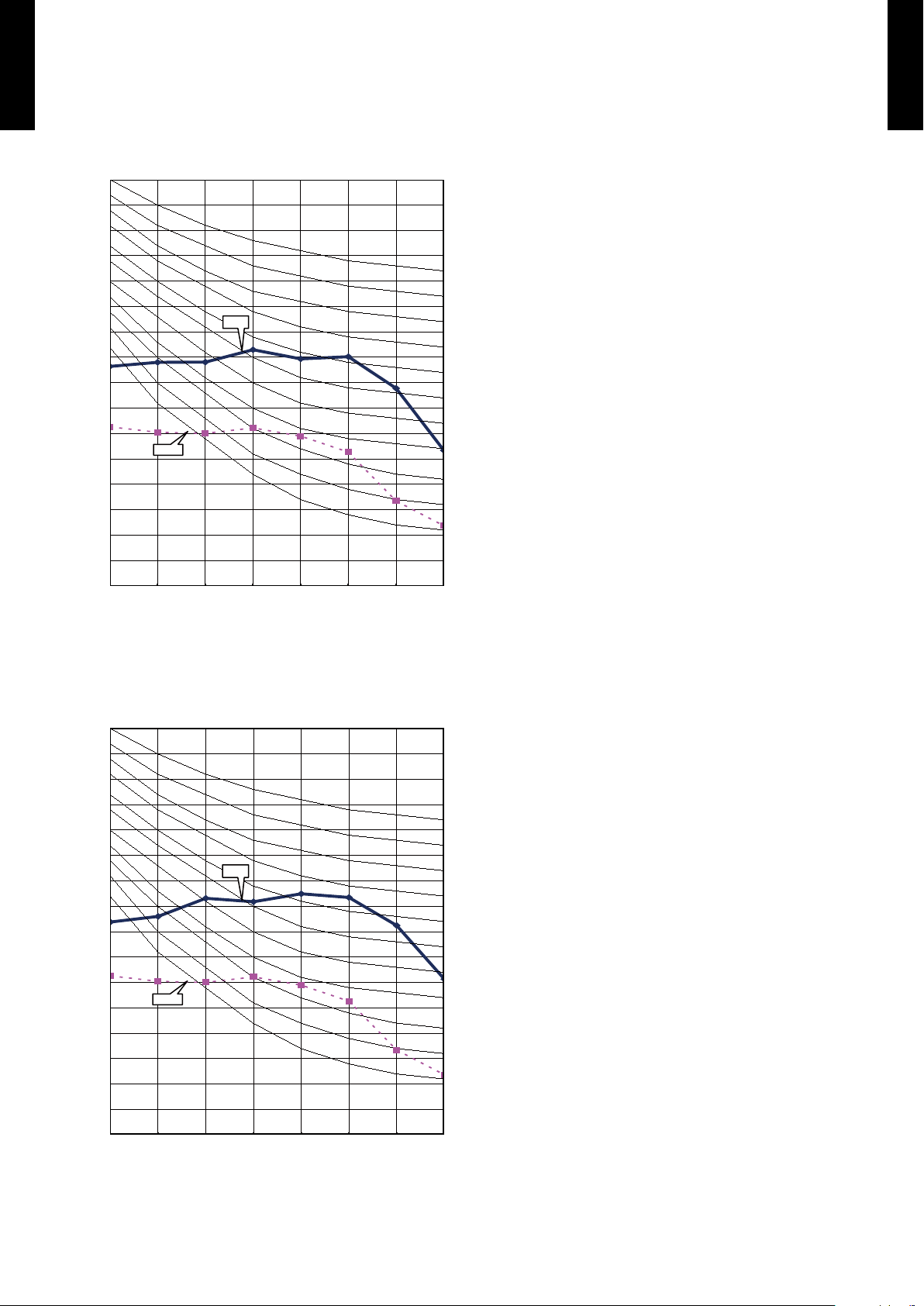
MODEL : ASU36CLX1
COOLING
z
80
70
60
50
40
30
20
Octave band sound pressure level, dB:(0 dB= 0.00 02µbar)
10
NC-65
NC-60
NC-55
NC-50
NC-45
NC-40
NC-35
NC-30
NC-25
NC-20
NC -15
0
63 125 250 50 0 1,000 2 ,000 4, 000 8,0 00
Octave band center frequ ency,Hz
- (01 - 13) -
Page 17

SOUND LEVEL CHECK POINT8-2.
39-3/8 in. (1m)
31-1/2 in. (0.8 m)
WALL MOUNTED TYPE
ASU30-36CLX1
WALL MOUNTED TYPE
ASU30-36CLX1
- (01 - 14) -
Page 18

ELECTRIC CHARACTERISTICS9.
WALL MOUNTED TYPE
ASU30-36CLX1
Model name ASU30CLX1, ASU36CLX1
Volt ag e V 208/230~
Power supply
Frequency Hz 60
Max. operating current A 0.3
Connection cable AWG 14
*)Wiring Spec.
Limited wiring length ft. 167
*) Wiring Spec.
Selected Sample
(Selected based on Japan Electrotechnical Standard and Codes Committee E0005)
WALL MOUNTED TYPE
ASU30-36CLX1
- (01 - 15) -
Page 19

SAFETY DEVICES10.
WALL MOUNTED TYPE
ASU30-36CLX1
Model
WALL MOUNTED TYPE
ASU30-36CLX1
Protection form
AS U30C LX1 ASU36CLX1
Circuit protection Current fuse (PCB) 3.15A 250V
Terminal protection Current fuse 3A 250V
Fan motor protection Thermal protection program
212
203+9
+27
-18
°F (100
°F (95+5
-18
+15
°C) OFF
-10
°C) ON
-10
- (01 - 16) -
Page 20

EXTERNAL INPUT & OUTPUT11.
Indoor
control PC board Connected unit
Ex.) Switch
Connector
1
3
Signal
Field supply
* Make the distance from the PC board to the connected unit within 33 ft. (10m).
Contact capacity : 5VDC or more, 20mA or more.
Please use the non-polar relays and switches.
*33 ft. (10 m)
Operation
Stop
ON
OFF
Input signal
Indoor unit
Connector INPUT OUTPUT REMARKS
WALL MOUNTED TYPE
ASU30-36CLX1
CN14
Control input
(Operation / stop)
-
CN16 - Operation status output
See external
input/output settings
for details.
WALL MOUNTED TYPE
ASU30-36CLX1
EXTERNAL INPUT11-1.
CONTROL INPUT (Operation/Stop)
The air conditioner can be remotely operated by means of the following on-site work.
Operation is started at the following contents by adding the contact input of a commercial ON/OFF switch to a
connector on the external control PC board and turning it ON.
Initial starting after power turned on Starting other than at the left
Operation mode Auto changeover Mode at previous operation
Set temperature 75°F (24°C) Temperature at previous operation
Air ow mode AUTO Mode at previous operation
Up-down air direction (swing) Standard air direction (swing OFF) Air direction at previous operation
Left-right air direction (swing) Standard air direction (swing OFF) Air direction at previous operation
Circuit diagram example
z
Parts (Optional)
z
Parts name Model name
External connect kit UTY-XWZ X
Wire (External input)
- (01 - 17) -
Page 21

EXTERNAL OUTPUT11-2.
Field supply
Ex.)Display
Indoor
control PC board
Connected unit
Ex.)Relay unit
1
2
Signal
Relay
power
supply
V
Connector
* Make the distance from the PC board to the connected unit within 33ft. (10m).
Relay spec. : Max.24VDC, 10mA to less than 500mA.
*33 ft.
(10 m)
24V DC
ON
OFF
Operation
Stop
Indoor unit
Output signal
WALL MOUNTED TYPE
ASU30-36CLX1
OPERATION STATUS OUTPUT
An air conditioner operation status signal can be output.
Circuit diagram example
z
WALL MOUNTED TYPE
ASU30-36CLX1
Parts (Optional)
z
Wire (External output)
Parts name Model name
External connect kit UTY-XWZ X
- (01 - 18) -
Page 22

FUNCTION SETTING12.
JM5
JM6
JM7
JM8
JM10
JM5
JM6
JM7
JM8
JM10
INDOOR UNIT 12-1.
WALL MOUNTED TYPE
ASU30-36CLX1
INDOOR UNIT
WALL MOUNTED TYPE
ASU30-36CLX1
JM 5 Auto restart
Jumper Wire
SWITCH POSITION
JM 6
JM 7
JM 8
JM 10
Room temperature correction
Remote controller signal code
MAIN PCB
- (01 - 19) -
Page 23

WALL MOUNTED TYPE
ASU30-36CLX1
JUMPER WIRE SETTING
Auto restart setting (JM5)
z
(
Factory setting)
WALL MOUNTED TYPE
ASU30-36CLX1
.
JM 5 Auto restart
Room temperature correction setting (JM6, JM7)
z
Remote controller signal code setting (JM8, JM10)
z
Connect Validity
Disconnect Invalidity
JM 6 JM 7
Connect Connect Standard
Disconnect Connect Slightly lower control
Connect Disconnect Slightly lower control
Disconnect Disconnect Lower control
Jumper wire
JM 8 JM 10
Connect Connect A
Disconnect Connect B
Room temperature correction
Cooling Drying
(
Remote controller
signal code
(
Factory setting)
Factory setting)
Connect Disconnect C
Disconnect Disconnect D
REMOTE CONTROLLER SIGNAL CODE SETTING
Use the following steps to select the signal code of the remote controller.
(Note that the air conditioner cannot receive a signal code if the air conditioner has not been set for the signal code.)
Press the START/STOP button until only the clock is displayed on the remote controller display.1.
Press the MODE button for at least ve seconds to display the current signal code (initially set to 2.
Press the SET TEMP. (3.
Match the code on the display to the air conditioner signal code.
Press the MODE button again to return to the clock display. The signal code will be changed.4.
If no buttons are pressed within 30 seconds after the signal code is displayed, the system returns to the original clock
display. In this case, start again from step 1.
The air conditioner signal code is set to A prior to shipment. Contact your retailer to change the signal code.
The remote controller resets to signal code A when the batteries in the remote controller are replaced. If you use a
signal code other than signal code A, reset the signal code after replacing the batteries.
If you do not know the air conditioner signal code setting,try each of the signal codes (
nd the code which operates the air conditioner.
) ( ) button to change the signal code between → → → .
→ → → .) until you
).
- (01 - 20) -
Page 24

OPTIONAL PARTS13.
SUMOTUWETH FR
SA
AM
PM
3 6 9
12 15 18 21
WALL MOUNTED TYPE
ASU30-36CLX1
Exterior Parts name Model No. Summary
WALL MOUNTED TYPE
ASU30-36CLX1
Wired remote
controller
Apple-catechin
lter
Ion
deodorisation
lter
UTY- RNBYU
UTR- FA13 -1
UTR- FA13 -2
Unit control is performed by
wired remote controller.
Fine dust, invisible mold
spores, and harmful
microorganisms are absorbed
onto the lter by static
electricity, and further growth
is inhibited and deactivated
by the polyphenol ingredient
extracted from apples.
The lter deodorizes by
powerfully decomposing
absorbed odors using the
oxidizing and reducing effects
of ions generated by the ultra
ne-particle ceramic.
External
connect kit
UTY-X WZ X
Use to connect with various
peripheral devices and air
conditioner PC board.
- (01 - 21) -
Page 25

2. OUTDOOR UNIT
SINGLE TYPE :
AOU30CLX1
AOU36CLX1
DTR_AO070E_02
2011.02.10
Page 26

2. OUTDOOR UNIT
CONTENTS
1. SPECIFICATIONS
OUTDOOR UNIT
AOU30-36CLX1
2. DIMENSIONS
3. REFRIGERANT CIRCUIT
4. WIRING DIAGRAMS
.............................................................................................. 02 - 01
........................................................................................................ 02 - 02
............................................................................ 02 - 03
........................................................................................ 02 - 04
OUTDOOR UNIT
AOU30-36CLX1
5. CAPACITY COMPENSATION RATE FOR PIPE LENGTH AND
HEIGHT DIFFERENCE
6. ADDITIONAL CHARGE CALCULATION
7. AIR FLOW
................................................................................................................ 02 - 07
8. OPERATION NOISE
8-1. NOISE LEVEL CURVE
8-2. SOUND LEVEL CHECK POINT
.................................................................................. 02 - 05
......................................... 02 - 06
......................................................................................... 02 - 08
.................................................................................... 02 - 08
..................................................................... 02 - 09
9. ELECTRIC CHARACTERISTICS
10. SAFETY DEVICES
.............................................................................................02 - 11
........................................................... 02 - 10
Page 27

SPECIFICATIONS1.
Type INVERTER COOLING ONLY
Model name AOU30CLX1 AOU36CLX1
Power source 208/230V~ 60Hz
Available voltage range 187-253V ~ 60Hz
Starting current A 14.2 17.0
Airow
Fan
OUTDOOR UNIT
AOU30-36CLX1
Sound pressure level
Heat exchanger type
Compressor
Refrigerant
Refrigerant oil Ty pe POE (RB68)
Enclosure
Dimensions
( H×W×D)
Weight
Connection pipe
Operation range
rate
Type × Q'ty Propeller fan×1
Motor output W 100
Type × Q'ty Rotary x 1
Motor output W 2,10 0
Net
Gross
Net
Gross 150 (68)
Size
Method Flare
Pre-charge length
Max. length 164 (50)
Max. height difference 98 (30)
Cooling
Heating - -
Cooling
Heating - Dimensions
(H × W × D)
Fin pitch FPI 20
Rows x Stages 2 × 38
Pipe type Copper
Fin type Aluminum
Type R410A
Charge
Material Steel
Color
Liquid
Gas Ø5/8 (Ø15.88)
Cooling
Heating - -
CFM
3
(m
/h)
dB(A)
in. 31-7/16 x 35-7/16 x 1-7/16
mm 798 x 900 x 36.4
lbs.oz. 4lbs.10.1oz.
kg 2.1
mm 830 x 900 x 330
inch 32-3/4 x 35-3/8 x 13
mm 970 x 1050 x 445
inch 38-1/4 x 41-1/2 x 17-1/2
lbs.( kg)
in.
(mm)
ft.
(m)
°F
(°C)
2,119 (3,600) 2,119 (3,600)
54 54
Beige
Approximate color of MUNSELL 10YR7.5/1.0
135 (61)
Ø3/8 (Ø9.52)
66 (20)
14 to 115 (-10 to 46)
OUTDOOR UNIT
AOU30-36CLX1
Note :
Specications are based on the following conditions.
Cooling : Indoor temperature of 80°F(26.67°C)DB / 67°F(19.44°C)WB,and outdoor temperature of 95°F(35°C)DB/ 75°F(23.9°C)WB.
Pipe length : 24ft.7in.(7.5 m), Height difference : 0 m.(Outdoor unit - Indoor unit)
- (02 - 01) -
Page 28

DIMENSIONS2.
23-5/8 (600)
or more
9-27/32 (250)
or more
9-27/32 (250)
or more
11-13/16 (300)
or more
23-5/8 (600)
or more
3-15/16 (100)
or more
11-13/16 (300)
or more
3-15/16 (100)
or more
9-27/32 (250) or more
(Service space)
Top view
Front view
Side view
Bottom view
3(77)
35-3/8 (900)
32-3/4 (830)
17-3/8 (440)
7/8 (21)
15-3/4 (400)
13 (330)
7-3/4 (196)
5-3/4 (147)
6-3/4 (170)
14-5/8 (370)
25-5/8 (650)
Air Flow
1-1/4
(31)
1/2
(12)
3-7/8
(99)
3/8
(9)
MODEL : AOU30CLX1, AOU36CLX1
Unit : in.(mm)
OUTDOOR UNIT
AOU30-36CLX1
OUTDOOR UNIT
AOU30-36CLX1
INSTALLATION PLACE
When there are obstacles at the
back or front sides.
When there are obstacles at the
back, side(s), and top.
When there are obstacles at the
back, side with the installation of
more than one unit.
- (02 - 02) -
Page 29

REFRIGERANT CIRCUIT3.
3-Way
valve
(Small)
3-Way
valve
(Large)
Strainer
Strainer
Muffler
Pressure
switch
4-Way valve
Expansion valve
Heat exchanger
( INDOOR )
Heat exchanger
( OUTDOOR )
Sub-accumulator
Compressor
Cooling
MODEL : AOU30CLX1, AOU36CLX1
OUTDOOR UNIT
AOU30-36CLX1
OUTDOOR UNIT
AOU30-36CLX1
Refrigerant pipe diameter
Liquid : 3/8" (9.52 mm)
Gas : 5/8" (15.88 mm)
- (02 - 03) -
Page 30

WIRING DIAGRAMS4.
MODEL : AOU30CLX1, AOU36CLX1
OUTDOOR UNIT
AOU30-36CLX1
OUTDOOR UNIT
AOU30-36CLX1
- (02 - 04) -
Page 31

CAPACITY COMPENSATION RATE FOR PIPE LENGTH 5.
AND HEIGHT DIFFERENCE
MODEL : AOU30CLX1, AOU36CLX1
Pipe length
COOLING
OUTDOOR UNIT
AOU30-36CLX1
Indoor unit is upper
Height
difference H
Indoor unit is under
Ú
1
than outdoor unit.
Ú
2
than outdoor unit
30m 99ft. - - - - 0.932 0.929 0.924
20m 66ft. - - - 0.945 0.947 0.945 0.940
10m 33ft. - - 0.984 0.961 0.963 0.960 0.956
7.5m 25ft. - 0.988 0.988 0.965 0.967 0.964 0.959
5m 16ft. 0.990 0.992 0.992 0.968 0.971 0.968 0.963
0m 0ft. 0.998 1.000 1.000 0.976 0.979 0.976 0.971
-5m -16ft. 0.998 1.000 1.000 0.976 0.979 0.976 0.971
-7.5m -25ft. - 1.000 1.000 0.976 0.979 0.976 0.971
-10m -33ft. - - 1.000 0.976 0.979 0.976 0.971
-20m -66ft. - - - 0.976 0.979 0.976 0.971
-30m -99ft. - - - - 0.979 0.976 0.971
5m 7.5m 10m 20m 30m 40m 50m
16ft. 25ft. 33ft. 66ft. 99ft. 131ft. 164ft.
OUTDOOR UNIT
AOU30-36CLX1
Height difference H
Indoor unit
H H
Outdoor unit
Connection pipe
1 Indoor unit is upper than outdoor unit.
Outdoor unit
Indoor unit
Connection pipe
2 Indoor unit is under than outdoor unit.
- (02 - 05) -
Page 32

ADDITIONAL CHARGE CALCULATION6.
MODEL : AOU30CLX1, AOU36CLX1
Refrigerant type R410A
Refrigerant amount
REFRIGERANT CHARGE
OUTDOOR UNIT
AOU30-36CLX1
z
Total pipe length
Additional charge
lbs. oz. 4lbs. 10.1oz.
g 2100
ft. 66 or less 98 131 16 4
m 20 or less 30 40 50
oz. 0 14 .1 28.2 42.3
g 0 400 800 1200
0.43oz./ft.
(40 g /m)
OUTDOOR UNIT
AOU30-36CLX1
- (02 - 06) -
Page 33

AIR FLOW7.
MODEL : AOU30CLX1, AOU36CLX1
Cooling
z
Number of
rotations
(r.p.m.)
3600 m
Air ow
3
/h
OUTDOOR UNIT
AOU30-36CLX1
850
1000 l/s
2119 CFM
OUTDOOR UNIT
AOU30-36CLX1
- (02 - 07) -
Page 34

OPERATION NOISE8.
NOISE LEVEL CURVE8-1.
MODEL : AOU30CLX1
Cooling
z
80
70
OUTDOOR UNIT
AOU30-36CLX1
60
50
40
30
20
Octave band sound pressure level, dB:(0 dB= 0.0002µbar)
10
NC-65
NC-60
NC-55
NC-50
NC-45
NC-40
NC-35
NC-30
NC-25
NC-20
NC -15
OUTDOOR UNIT
AOU30-36CLX1
0
63 125 250 50 0 1,000 2 ,000 4,000 8,0 00
Octave band center frequency,Hz
MODEL : AOU36CLX1
Cooling
z
80
70
60
50
40
30
20
Octave band sound pressure level, dB:(0 dB= 0.0002µbar)
10
NC-65
NC-60
NC-55
NC-50
NC-45
NC-40
NC-35
NC-30
NC-25
NC-20
NC -15
0
63 125 250 50 0 1,000 2 ,000 4,000 8,0 00
Octave band center frequency,Hz
- (02 - 08) -
Page 35

SOUND LEVEL CHECK POINT8-2.
3ft. 3-
3/8
in. (1m)
OUTDOOR UNIT
AOU30-36CLX1
OUTDOOR UNIT
AOU30-36CLX1
- (02 - 09) -
Page 36

ELECTRIC CHARACTERISTICS9.
Model Name AO U30CLX1 AOU36CLX1
Power Supply
*1) Max. Operating Current A 17. 0 18.0
Starting Current A 14.2 17. 0
*2) Wiring Spec.
OUTDOOR UNIT
AOU30-36CLX1
*1) The maximum current is the total current of indoor unit and outdoor unit.
*2) Wiring Spec.
Selected Sample
(Selected based on Japan Electrotechnical Standard and Codes Committee E00005)
*3) Limited Wiring Length:
This is the wiring length in case voltage descent is less than 2%.
When the wiring length becomes long, please select the wiring of a more larger diameter.
Voltage V 208 / 230~
Frequency Hz 60
Main Fuse (Circuit breaker)
Current
Power Cable AWG 10
*3) Limited wiring length ft. 60 57
A 30
OUTDOOR UNIT
AOU30-36CLX1
- (02 - 10) -
Page 37

SAFETY DEVICES10.
Model
Protection form
AOU30CLX1, AOU36CLX1
Current fuse
(NEAR THE TERMINAL)
Circuit protection
OUTDOOR UNIT
AOU30-36CLX1
Current fuse
(MAIN PRINTED
5A 250V
3.15A 250V x 2
OUTDOOR UNIT
AOU30-36CLX1
CIRCUIT BOARD)
Fan motor protection
High Pressure
Protection
Compressor
protection
Thermal protection
program
Pressure Switch
Thermal protection program
(COMPRESSOR TEMP.)
Thermal protection program
(DISCHARGE TEMP.)
Thermal protection program
(OUTDOOR TEMP.)
(Cooling / Dry mode)
OFF : 230
ON : 221
+27
-18 -10
+27
-18 -10
°F (105
OFF : 4.2±0.1MPa
ON : 3.2±0.15MPa
OFF : 226°F (108°C)
ON : 176°F (80°C)
OFF : 230°F (110°C)
ON : After 7 minutes
OFF : -13°F (-25°C)
ON : -4°F (-20°C)
°F (110
+15
+15
°C)
°C)
- (02 - 11) -
 Loading...