

Page 1

SPLIT TYPE
ROOM AIR CONDITIONER
DUCT
type
Models Indoor unit Outdoor unit
ARTG30LHTA
ARTG36LHTA
ARTG45LHTA
ARTG54LHTA
AOTG30LATL
AOTG36LATL
AOTG45LATL
AOTG54LATL
INVERTER
SERVICE
INSTRUCTION
R410A
Page 2

CONTENTS
1. SPECIFICATIONS
1. DESCRIPTION OF EACH CONTROL OPERATION
1-1-1 COOLING CAPACITY CONTROL......................................................................
1-1 COOLING OPERATION............................................................................................
1-4 AUTO CHANGEOVER OPERATION........................................................................
1-5 INDOOR FAN CONTROL.........................................................................................
1-6 OUTDOOR FAN CONTROL
......................................................................................
1-7 COMPRESSOR CONTROL......................................................................................
01-01
01-01
1-2-1 HEATING CAPACITY CONTROL......................................................................
1-2 HEATING OPERATION.............................................................................................
01-02
01-02
1-3-1 INDOOR UNIT CONTROL.................................................................................
1-3 DRY OPERATION......................................................................................................
01-03
01-03
01-04
01-06
01-08
01-09
1-8 TIMER OPERATION CONTROL...............................................................................
01-10
1-9 ELECTRONIC EXPANSION VALVE CONTROL......................................................
01-12
1-10 TEST OPERATION CONTROL...............................................................................
01-12
1-11 PREVENT TO START FOR 3 MINUTES (3 MINUTES ST)....................................
01-12
1-12 4-WAY VALVE EXTENSION SELECT....................................................................
01-12
1-13
AUTO RESTART
.....................................................................................................
01-14
1-14
PUMP DOWN..........................................................................................................
01-13
1-15 COMPRESSOR PREHEATING...............................................................................
01-14
1-16 MINIMUM HEAT OPERATION................................................................................
01-14
1-20 VARIOUS PROTECTIONS......................................................................................
01-18
1-21 COMPRESSOR STOP CONTROL..........................................................................
01-20
1-19 OFF DEFROST OPERATION CONTROL...............................................................
01-17
6. REFRIGERANT CAUTION -R410A-
3. DISASSEMBLY PROCESS
2-1-2 OUTDOOR UNIT DISPLAY................................................................................
2-1-1 WIRED REMOTE CONTROLLER DISPLAY......................................................
2-1 ERROR DISPLAY......................................................................................................
2. TROUBLE SHOOTING
2-2 TROUBLE SHOOTING WITH ERROR CODE..........................................................
2-3 TROUBLE SHOOTING WITH NO ERROR CODE....................................................
2-4 SERVICE PARTS INFORMATION............................................................................
02-01
02-01
02-03
02-30
02-04
02-35
DISASSEMBLY PROCESS( FOR ARTG45 / 54LHTA )............................................
03-01
1-18 DEFROST OPERATION CONTROL.......................................................................
01-15
1-17 ECONOMY OPERATION........................................................................................
01-14
1-22 DESCRIPTION OF DISPLAY UNIT.........................................................................
01-21
Page 3

2 . TROUBLE SHOOTING
R410A
DUCT type
INVERTER
Page 4

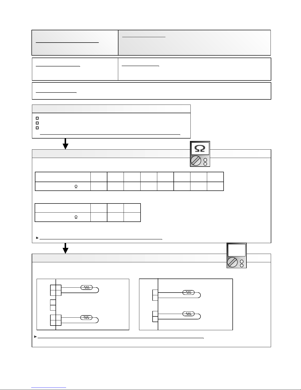
Indoor Room Thermistor Error
Wired Remote Controller
Communication Error
Error Contents
Trouble
shooting
02-01
2 ERROR DISPLAY
2-1 INDOOR UNIT AND WIRED REMOTE CONTROLLER DISPLAY
Serial Communication Error
Indoor Unit Fan Motor1 Error
Indoor Heat Ex. Thermistor Error
Drainage Error
1,2
3
4
5
6
7
8
9
1- 9
10
11
12
13
IPM Error
Error
Code
11
12
39
41
42
51
53
59
5U
63
65
71
72
Fan Motor Driving Circuit Error
Indoor Unit Error
Inverter Error
Indoor Unit Fan Motor2 Error
Error Contents
Trouble
shooting
17
18
19
20
21
22
23
24
25
26
Error
Code
84
86
94
95
97
98
99
A1
A3
A5
Over Current Error
Discharge Thermistor Error
Current sensor Error
Pressure sensor Error
Compressor Thermistor Error
W
AR-WAF1E
AR-WDD1E
hen "Er" in Temperature Display is displayed, inspection of the air conditioning system is necessary.
Please consult authoilzed service personnel.
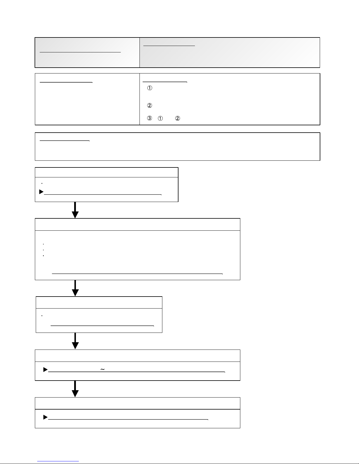
1. SELF - DIAGNOSIS
SUMOTUWETH FR
SA
Unit number (usually 0)
Error code
ex. Self-diagnosis check
Compressor Control Error
Outdoor Unit Fan Motor 1 Error
Outdoor Unit Fan Motor 2 Error
4-way Valve Error
Discharge Temp. Error
Compressor Temp. Error
Low Pressure Error
When there is an error on the indoor unit:
Code : Er 41.1
R.C. address : 00
Error
Mo
10:00
Monitor
Code : XXXXXX
R.C. address : 00
Error
Mo
10:00
Monitor
Error code*
Address number of the
relevant indoor unit
a 1 digit number.
Installation manual of the indoor unit.
14
15
16
73
74
77
Outdoor Thermistor Error
Heat Sink Thermistor Error
Heat Ex. Liquid Outlet
Thermistor Error
Page 5

02-02
2. ERROR CODE HISTORY DISPLAY
Up to 16 memorized error codes may be displayed for the indoor unit connected to the remote controller.
1. Stop the air conditioner operation.
2. Press the SET TEMPERATURE buttons , simultaneously for 3 seconds
or more to start the self-diagnosis.
4. Press the SET TEMPERATURE buttons , simultaneously for 3 seconds or more
or there is no key input for 60 seconds to stop the display.
3. Press the SET TEMPERATURE button to select the error history number.
SU MOTU WETH FR SA
Error code
Error history number
0 1 2 3 4 5 6 7
F E d c b A 9 8
Lower
Raise
Page 6

2. ERROR DETECTION
1. OUTDOOR UNIT Indicator PCB
Display when an error occurs.
POWER
ERROR
PUMP
DOWN
LOW
NOISE
PEAK
CUT
MODE (L1) (L2) (L3) (L4) (L5) (L6)
Blink
(Hi speed)
Check that the “ERROR” LED blinks, then press the [Enter] button once.
For details, refer to the following table.
02-03
LEDs
Buttons
2-1-2 OUTDOOR UNIT DISPLAY
Error Contents
POWER
MODE
ERROR
Serial forward transfer error(after operation)
2
2
2
2
2
2
2
2
2
2
2
1
(L1) (L2) (L6)(L5)(L4)(L3)
IPM Error
Indoor Unit Error
Inverter Error
Over Current Error
Discharge Thermistor Error
Outdoor Thermistor Error
Heat Sink Thermistor Error
Current sensor Error
Pressure sensor Error
Heat Ex. Liquid Middle
Thermistor Error
Compressor Thermistor Error
Compressor Control Error
Outdoor Unit Fan Motor 1 Error
Outdoor Unit Fan Motor 2 Error
4-way Valve Error
Discharge Temp. Error
Compressor Temp. Error
Low Pressure Error
2
2
2
2
2
2
2
2
2
2
2
1
1
1
5
6
3
6
5
7
1
7
2
7
3
7
3
7
4
7
7
8
4
8
6
8
6
9
4
9
5
9
7
9
8
9
9
10
1
10
3
10 5
15
Serial forward transfer error(during operation)
Heat Ex. Liquid Outlet
Thermistor Error
High Pressure Switch Error
LED DISPLAY
PUMP
DOWN
LOW
NOISE
PEAK
CUT
Trouble
shooting
2
1 - 9
10
11
12
13
14
15
16
17
18
19
20
21
22
23
24
25
26
1 ~ : 1~ 15 Times Blinking 15
: Light ON: Light OFF
2 : 2
Times Blinking
Page 7

Trouble shooting 1
OUTDOOR UNIT Error Method:
Detective Actuators: Detective details:
Forecast of Cause:
OK
Indicate or Display:
Refer to error code table.
YESYES
NO
Serial Communication Error
(Serial Reverse Transfer Error)
Outdoor unit Main PCB
Outdoor unit Fan motor
1. Connection failure 2. External cause 3. Main PCB failure 4. Active filter module failure
5. Transistor PCB (IPM) failure 6. Filter PCB failure 7. Outdoor unit Fan motor failure
Check Point 1-1 : Reset the power and operate
Does error indication reappear?
Check Point 1-2 : Check external cause such as noise
Check if the ground connection is proper.
Check if there is any equipment that causes harmonic wave
near the power cable (Neon light bulb or any electronic
equipment which causes harmonic wave).
Check Point 2 : Check connection
Check any loose or removed connection line of
between indoor unit and outdoor unit.
>> If there is an abnormal condition, correct it by
referring to Installation Manual or Data &
Technical Manual.
Check connection condition in control unit.
(If there is loose connector, open cable or mis-wiring)
Check Point 3 : Check the voltage of power supply
Check the voltage of power supply
>> Check if AC198V(AC220V-10%) - 264V(AC240V+10%) appears
at outdoor unit terminal L - N.
When the indoor unit cannot receive the serial signal from Outdoor unit
more than 2minutes after power ON, or the indoor unit cannot receive
the serial signal more than 15seconds during normal operation.
02-04
2-2 TROUBLE SHOOTING WITH ERROR CODE
OK
Check Point 4 : Check serial signal (Reverse transfer signal)
Check serial signal (Reverse transfer signal)
>> Check if indicated value swings between AC70V and AC130V at outdoor unit terminal 1 - 3.
>> If it is abnormal, Check the parts as follows.
- Outdoor unit fan motor (PARTS INFORMATION 5)
- Active filter module (PARTS INFORMATION 4)
- Transistor PCB (IPM) (PARTS INFORMATION 7)
- Filter PCB (Check the wire of CN110)
>> If Outdoor fan motor is abnormal, replace Outdoor unit fan motor and Main PCB.
>> If Active filter module or IPM is abnormal, replace it.
>> If the parts are normal, replace Main PCB.
1
2
3
L
N
RED
WHITE
BLACK
BLACK
WHITE
+
-
Page 8

Trouble shooting 2
INDOOR UNIT Error Method:
Detective Actuators: Detective details:
Forecast of Cause:
OK
Indicate or Display:
Refer to error code table.
YESYES
NO
OK
Serial Communication Error
(Serial Forward Transfer Error)
Indoor unit Controller PCB
1. Connection failure 2. External cause 3. Controller PCB failure
Check Point 1-1 : Reset the power and operate
Does error indication reappear?
Check Point 1-2 : Check external cause such as noise
Check if the ground connection is proper.
Check if there is any equipment that causes harmonic wave
near the power cable (Neon light bulb or any electronic
equipment which causes harmonic wave).
Check Point 2 : Check connection
Check any loose or removed connection line of
between indoor unit and outdoor unit.
>> If there is an abnormal condition, correct it by
referring to Installation Manual or Data &
Technical Manual.
Check connection condition in control unit.
(If there is loose connector, open cable or mis-wiring)
Check Point 3 : Check the voltage of power supply
Check the voltage of power supply
>> Check if AC198V(AC220V-10%) - 268V(AC240V+10%) appears
at outdoor unit terminal L - N.
Check Point 4 : Check serial signal (Forward transfer signal)
Check serial signal (Forward transfer signal)
>> Check if indicated value swings between AC70V and AC130V at outdoor unit terminal 2 - 3.
>> If it is abnormal, replace Controller PCB.
When the outdoor unit cannot properly receive the serial signal from
indoor unit for 10 seconds or more.
02-05
1
2
3
L
N
RED
WHITE
BLACK
BLACK
WHITE
+
-
Page 9

Trouble shooting 3
INDOOR UNIT Error Method:
Detective Actuators: Detective details:
Forecast of Cause:
Check Point 2 : Check Wired Remote Controller and Controller PCB
Check Point 1 : Check the connection of terminal
OKOK
Indicate or Display:
Wired Remote Controller
Communication Error
Indoor unit Controller PCB
Wired Remote Controller (Option)
1. Connection failure 2. Wired Remote Controller failure 3. Controller PCB failure
Check & correct the followings.
Check the connection of terminal between Wired Remote Controller and indoor unit,
and check if there is a disconnection of the cable.
When the indoor unit cannot properly receive the signal from
Wired Remote Controller for 1 minute or more.
02-06
Refer to error code table.
>> If it is DC13V, Remote Control is failure. (Controller PCB is normal) >> Replace Remote Control
>> If it is DC 0V, Controller PCB is failure. (Check Remote Control once again) >> Replace Controller PCB
Check Voltage at CN14(ARTG30/36LHTA),CN140(ARTG45/54LHTA) of Controller PCB. (terminal 1-3)
(Power supply to Remote Control)
Page 10

Trouble shooting 4
INDOOR UNIT Error Method:
Indicate or Display:
Detective Actuators: Detective details:
Forecast of Cause :
Fan Motor Drive Circuit Error
Indoor Unit Power Supply PCB
When a momentary power cut off.
When do not start fan motor.
1. External cause 2. Conenection of connector failure 3. Power Supply PCB failure
Check Point 3 : Replace Power supply PCB
If Check Point 1, 2 do not improve the symptom, replace Power supply PCB.
02-07
Refer to error code table.
OKOK
Check Point 2 : Check connection of Connector
Check if connector is removed.
Check erroneous connection.
Check if cable is open.
>>Upon correcting the removed connector or mis-wiring, reset the power.
Check Point 1 : Check external cause at Indoor and Outdoor (Voltage drop or Noise)
Instant drop : Check if there is a large load electric apparatus in the same circuit.
Momentary power failure : Check if there is a defective contact or leak current
in the power supply circuit.
Noise : Check if there is any equipment causing harmonic wave near electric line.
(Neon bulb or electric equipment that may cause harmonic wave)
Check the complete insulation of grounding.
OKOK
Page 11

Detective Actuators:
Indoor Unit Controller PCB Circuit
Indoor Temperature Thermistor
Detective details:
Indoor unit thermistor is open or short is detected always.
Forecast of Cause :
1. Connector failure connection 2. Thermistor failure 3. Controller PCB failuer
Check Point 2 : Remove connector and check Thermistor resistance value
Thermistor Characteristics (Rough value)
If Thermistor is either open or shorted, replace it and reset the power.
Check Point 1 : Check connection of Connector
Check if connector is loose or removed
Check erroneous connection
Check if thermistor cable is open
>>Reset Power when reinstalling due to removed connector or incorrect wiring.
6.58.010.012.515.820.225.933.6
3.594.355.3Resistance value (k )
OK
OK
Check Point 3 : Check voltage of Controller PCB (DC5.0V)
Make sure circuit diagram of each indoor unit and check terminal voltage at Thermistor (DC5.0V)
If the voltage does not appear, replace Controller PCB and execute the check operation again.
DC
02-08
Trouble shooting 5
INDOOR UNIT Error Method:
Indicate or Display:
Indoor Room Thermistor Error
Refer to error code table.
Temperature (°C )
Temperature (°C )
0
40 45 50
5 10 15 20 25 30 35
Resistance value (k )
H/E Thermistor
Room Temp. Thermistor
BLACK
BLACK
121
2
1 1
2 2
CN5
CN8
GRAY
GRAY
1
2
CN7
ARTG30 / 36LHTA
BLACK
BLACK
1
2
CN114
H/E Thermistor
Room Temp. Thermistor
BLACK
BLACK
1
2
CN110
ARTG45 / 54LHTA
Page 12

Thermistor Characteristics (Rough value)
If Thermistor is either open or shorted, replace it and reset the power.
Detective Actuators:
Indoor Unit Controller PCB
Heat Exchanger (MID) Thermistor
Detective details:
Indoor unit thermistor is open or short is detected always.
Forecast of Cause :
1. Connector failure connection 2. Thermistor failure 3. Controller PCB failuer
Check Point 1 : Check connection of Connector
Check if connector is loose or removed
Check erroneous connection
Check if thermistor cable is open
>>Reset Power when reinstalling due to removed connector or incorrect wiring.
OK
Check Point 2 : Remove connector and check Thermistor resistance value
02-09
Trouble shooting 6
INDOOR UNIT Error Method:
Indicate or Display:
Indoor Heat Ex. Thermistor Error
Refer to error code table.
31.739.649.762.980.3103134176
17.120.825.6Resistance value (k )
Temperature (°C )
Temperature (°C )
0
40 45 50
5 10 15 20 25 30 35
Resistance value (k )
OK
Check Point 3 : Check voltage of Controller PCB (DC5.0V)
Make sure circuit diagram of each indoor unit and check terminal voltage at Thermistor (DC5.0V)
If the voltage does not appear, replace Controller PCB and execute the check operation again.
DC
H/E Thermistor
Room Temp. Thermistor
BLACK
BLACK
121
2
1 1
2 2
CN5
CN8
GRAY
GRAY
1
2
CN7
ARTG30 / 36LHTA
BLACK
BLACK
1
2
CN114
H/E Thermistor
Room Temp. Thermistor
BLACK
BLACK
1
2
CN110
ARTG45 / 54LHTA
Page 13

02-10
Trouble shooting 7
INDOOR UNIT Error Method:
Indicate or Display:
Indoor Unit Fan Motor1 Error
Refer to error code table.
Detective Actuators:
Detective details:
Forecast of Cause:
Check Point 1 : Check rotation of Fan
Check Point 2 : Check ambient temp. around motor
OK
OK
OK
Indoor unit Power Supply PCB
Indoor unit fan motor
1. Fan rotation failure 2. Fan motor winding open 3. Motor protection by surrounding temperature rise
4. Power Supply PCB failure 5. Indoor unit fan motor failure
Rotate the fan by hand when operation is off.
(Check if fan is caught, dropped off or locked motor)
>>If Fan or Bearing is abnormal, replace it.
Check excessively high temperature around the motor.
(If there is any surrounding equipment that causes heat)
>>Upon the temperature coming down, restart operation.
When the condition that actual frequency of Indoor Fan is
below 1/3 of target frequency is continued more than 56 seconds.
Check Point 4 : Replace Power Supply PCB
If Check Point 1- 3 do not improve the symptom, replace Power Supply PCB.
Check Point 3 : Check Indoor unit fan motor
Check Indoor unit fan motor. (PARTS INFORMATION 4)
>>If Indoor unit fan motor is abnormal, replace Indoor unit fan motor.
Page 14

Refer to error code table.
Trouble shooting 8
INDOOR UNIT Error Method:
Drainage Error
Indicate or Display:
Detective Actuators:
Indoor Unit Controller PCB Circuit
Float Switch
Detective details:
When Float switch is ON for more than 3 minutes.
Check Point 1 : Check Float Switch
Check operation of float switch. (any blocking by dust, etc.)
Remove Float switch and check ON/OFF switching operation
by using a meter.
>>If Float switch is abnormal, replace it.
ON OFF
OK
Forecast of Cause : 1. Float switch failure 2. Shorted connector/wire 3. Controller PCB failure
4. Drain pump failure 5. Hose clogging
Check Point 2 : Check Connector and Wire
Check loose contact of CN000(ARTG30/36LHTA) /
CN000(ARTG45/54LHTA) and shorted wire (pinched wire).
>>Replace Float switch if the wire is abnormal
Check Point 4 : Check Controller PCB
If Check Point 1 ~ 3 do not improve the symptom, change
Controller PCB and execute the check operation again.
Attention!!
Wall mount / Small size wall mount type
does not have a float switch.
In this case, replace Controller PCB
and set up the original address.
Please refer to.
OK
OK
Check Point 3 : Check Drain Hose
Check Drain Hose .
>>If there is Hose clogging. Please clear the clog.
02-11
Page 15

02-12
Trouble shooting 9
INDOOR UNIT Error Method:
Indicate or Display:
Indoor Unit Fan Motor2 Error
Refer to error code table.
Detective Actuators:
Detective details:
Indoor unit Power Supply PCB
Indoor unit fan motor
When the condition that actual frequency of Indoor Fan is
below 1/3 of target frequency is continued more than 56 seconds.
Forecast of Cause:
Check Point 1 : Check rotation of Fan
Check Point 2 : Check ambient temp. around motor
OK
OK
OK
1. Fan rotation failure 2. Fan motor winding open 3. Motor protection by surrounding temperature rise
4. Power Supply PCB failure 5. Indoor unit fan motor failure
Rotate the fan by hand when operation is off.
(Check if fan is caught, dropped off or locked motor)
>>If Fan or Bearing is abnormal, replace it.
Check excessively high temperature around the motor.
(If there is any surrounding equipment that causes heat)
>>Upon the temperature coming down, restart operation.
Check Point 4 : Replace Power Supply PCB
If Check Point 1- 3 do not improve the symptom, replace Power Supply PCB.
Check Point 3 : Check Indoor unit fan motor
Check Indoor unit fan motor. (PARTS INFORMATION 4)
>>If Indoor unit fan motor is abnormal, replace Indoor unit fan motor.
Page 16

Refer to error code table.
Inverter Error
YES
NO
OK
Check Point 1-2 : External cause
Inverter PCB
Error information received from Inverter PCB
1. External cause. 2. Power supply to Filter PCB to Inverter PCB
wiring disconnection, open 3. Filter PCB failure 4. Inverter PCB failure
Check if temporary voltage drop was not generated.
Check if temporary open was not generated.
Check if ground is connected correctly or there are no related cables near the
power line.
Check Point 2 : Check the wiring (Power supply to Filter PCB to Inverter PCB)
Connector and wiring connection state check
Cable open check
Replace Filter PCB and Inverter PCB.
Check Point 1-1 : Turn the power
on again.
Error displayed again?
Check Point 3 : Replace Filter PCB (INV) and Inverter PCB
02-13
Trouble shooting 10
Indicate or Display:
Detective Actuators:
Detective details:
OUTDOOR UNIT Error Method:
Forecast of Cause :
Page 17

Detective Actuators:
Detective details:
Forecast of Cause :
Check Point 3 : Check Outdoor Fan
OK
OK
Check Point 5 : Replace Main PCB
OKOK
OKOK
Check Point 1 : Check connections of Outdoor Unit Electrical Components
Outdoor unit Main PCB
Compressor
1. Defective connection of electric components 2. Outdoor Fan Operation failure
3. Outdoor Heat Exchanger clogged 4. Compressor failure 5. Main PCB failure
Check if connector is removed.
Check if the terminal connection is loose.
Check erroneous connection.
Check if cable is open.
>>Upon correcting the removed connector or mis-wiring, reset the power.
Check Point 2 : Check Outdoor Fan, Heat Exchanger
Is there anything obstructing the air distribution circuit?
Is there any clogging of Outdoor Heat Exchanger?
Is the Fan rotating by hand when operation is off ?
>> If the Fan Motor is locked, replace it.
Check Outdoor Fan Motor. (Refer to Trouble shooting 21,22)
>> If the Fan Motor is failure, replace it.
Check Point 4 : Check Compressor
(PARTS INFORMATION 2)
Check Compressor.
If Check Point 1 4 do not improve the symptom, change Main PCB.
When more than normal operating current to IPM in Main PCB flows,
the compressor stops.
After the compressor restarts, if the same operation is repeated within 40sec,
the compressor stops again.
If and repeats 5 times, the compressor stops permanently.
02-14
Trouble shooting 11
OUTDOOR UNIT Error Method:
IPM Error
Indicate or Display:
Refer to error code table.
Page 18

Refer to error code table.
Discharge Thermistor Error
OK
OK
D
C
CN62
THERMISTOR
(COMP SHELL)
THERMISTOR
(DIS.TEMP.)
BLACK
BLACK
BLA
C
K
BLA
C
K
1 2 3 4
1 2 3 4
Discharge temperature thermistor
Discharge temperature thermistor short detected
Discharge thermistor open detected
1. Connector connection failure, open
2. Thermistor failure
3. Main PCB failure
Check Point 1 : Check the connector connection and cable open
Connector connection state check
Cable open check
Check Point 2 : Check the thermistor
Thermistor characteristics check (Disconnect the thermistor from the PCB and check.)
* For the thermistor characteristics, refer to the "Service Parts Information 8".
Check Point 3 : Check voltage of Main PCB (DC5.0V)
Main PCB (CN62:1-2) voltage value = 5V
Remove the thermistor from Main PCB, check the voltage.
If the voltage does not appear, replace Main PCB,
and execute the check operation again.
Discharge temperature thermistor (CN62:1-2)
02-15
Trouble shooting 12
Indicate or Display:
Detective Actuators:
Detective details:
OUTDOOR UNIT Error Method:
Forecast of Cause :
Page 19

Refer to error code table.
Compressor Thermistor Error
D
C
Compressor temperature thermistor
Compressor temperature thermistor short detected
Compressor thermistor open detected
1. Connector connection failure, open
2. Thermistor failure
3. Main PCB failure
OK
OK
Check Point 1 : Check the connector connection and cable open
Connector connection state check
Cable open check
Check Point 2 : Check the thermistor
Thermistor characteristics check (Disconnect the thermistor from the PCB and check.)
* For the thermistor characteristics, refer to the "Service Parts Information 8".
Check Point 3 : Check voltage of Main PCB (DC5.0V)
Main PCB (CN62:3-4) voltage value = 5V
Remove the thermistor from Main PCB, check the voltage.
Compressor temperature thermistor (CN62:3-4)
If the voltage does not appear, replace Main PCB, and execute
the check operation again.
02-16
Trouble shooting 13
Indicate or Display:
Detective Actuators:
Detective details:
OUTDOOR UNIT Error Method:
Forecast of Cause :
CN62
THERMISTOR
(COMP SHELL1)
THERMISTOR
(DIS.TEMP.1)
BLACK
BLACK
BLA
C
K
BLA
C
K
1 2 3 4
1 2 3 4
Page 20

Refer to error code table.
D
C
CN63
THERMISTOR
THERMISTOR
SC (LP OUT)
(HEX. PIPE. OUT.)
BLACK
BLACK
1 2 3
4
1 2 3
4
B
LACK
BLA
C
K
Heat exchanger liquid temperature
thermistor
Heat exchanger outlet temperature thermistor short or open detected
1. Connector connection defective, open
2. Thermistor failure
3. Main PCB failure
OK
OK
Check Point 1 : Check the connector connection and cable open
Connector connection state check
Cable open check
Check Point 2 : Check the thermistor
Thermistor characteristics check (Disconnect the thermistor from the PCB and check.)
* For the thermistor characteristics, refer to the "Service Parts Information 8".
Check Point 3 : Check voltage of Main PCB (DC5.0V)
Main PCB (CN63:1-2) voltage value = 5V
Remove the thermistor from Main PCB, check the voltage.
Heat exchanger outlet temperature thermistor (CN63:1-2)
If the voltage does not appear, replace Main PCB, and execute
the check operation again.
If the voltage does not appear,
02-17
Heat Ex. Outlet Temp.
Thermistor Error
Trouble shooting 14
Indicate or Display:
Detective Actuators:
Detective details:
OUTDOOR UNIT Error Method:
Forecast of Cause :
5
5
Page 21

Refer to error code table.
Outdoor Thermistor Error
OK
D
C
CN61
(OUT TEMP.)
THERMISTOR
1 2 3
1 2 3
B
LA
CK
BLA
C
K
Outdoor temperature thermistor
Outdoor temperature thermistor short or open detected
1. Connector connection defective, open
2. Thermistor failure
3. Main PCB failure
OK
Check Point 1 : Check the connector connection and cable open
Connector connection state check
Cable open check
Check Point 2: Check the thermistor
Thermistor characteristics check (Disconnect the thermistor from the PCB and check.)
* For the thermistor characteristics, refer to the "Service Parts Information 8".
Check Point 3 : Check voltage of Main PCB (DC5.0V)
Main PCB (CN61:1-3) voltage value = 5V
Remove the thermistor from Main PCB, check the voltage.
Outdoor temperature thermistor (CN61:1-3)
If the voltage does not appear, replace Main PCB, and execute
the check operation again.
If the voltage does not appear, replace Main PCB
02-18
Trouble shooting 15
Indicate or Display:
Detective Actuators:
Detective details:
OUTDOOR UNIT Error Method:
Forecast of Cause :
Page 22

Refer to error code table.
Heat Sink Thermistor Error
Inverter PCB
Heat sink temperature thermistor (Built-in IPM) open/short detected
1. Inverter PCB failure
02-19
Trouble shooting 16
Indicate or Display:
Detective Actuators:
Detective details:
OUTDOOR UNIT Error Method:
Forecast of Cause :
If this error is displayed, replace Inverter PCB
Page 23

Trouble shooting 17
OUTDOOR UNIT Error Method:
Current Sensor Error
02-20
Indicate or Display:
Refer to error code table.
Detective Actuators:
Detective details:
Forecast of Cause :
Check Point 4 : Replace Main PCB
YES
NO
OK
Outdoor unit Main PCB
Check Point 2 :
Check connections of Outdoor Unit Electrical Components
Check if connector is removed.
Check if the terminal connection is loose.
Check erroneous connection.
Check if cable is open.
>>Upon correcting the removed connector or mis-wiring,
reset the power.
Check Point 1-2 :
Check external cause at Indoor and Outdoor
(Voltage drop or Noise)
1. Defective connection of electric components 2. External cause 3. Main PCB failure
Instant drop : Check if there is a large load electric
apparatus in the same circuit.
Momentary power failure : Check if there is a defective
contact or leak current in the
power supply circuit.
Noise : Check if there is any equipment causing harmonic
wave near electric line.(Neon bulb or electric
equipment that may cause harmonic wave)
Check the complete insulation of grounding.
Check Point 1-1 : Reset Power Supply and operate
Does Error indication show again?
When Input Current Sensor has detected 0A, while Inverter Compressor is
operating at higher than 56rps, after 1minute upon starting the Compressor.
(Except during the defrost operation)
If Check Point 1, 2 do not improve the symptom, change Main PCB.
Page 24

Refer to error code table.
Trouble shooting 18
OUTDOOR UNIT Error Method:
Indicate or Display:
OK
OK
Detective Actuators:
High pressure switch
Detective details:
Forecast of Cause :
1. High pressure switch connector disconnection, open
2. High pressure switch characteristics failure3. Main PCB failure
When the power was turned on, "high pressure switch : open" was detected.
Check Point 1 : Check the high pressure switch connection state
Connector and wiring connection state check
Cable open check
Check Point 2 : Check the high pressure switch characteristics
Switch characteristics check
* For the characteristics of high pressure switch, refer to below.
Check Point 3 : Replace Main PCB
Change Main PCB, and execute the check operation again.
02-21
Pressure Sencer Error
Type of contact
Characteristics of pressure switch
C
H
Pressure
Pressure switch 1
4.2 0.1MPa
3.2 0.15MPa
Contact : Short Open
Contact : Open Short
(CN101)
Page 25

02-22
Trouble shooting 19
INDOOR UNIT Error Method:
Indicate or Display:
Over Current Error
Refer to error code table.
Detective Actuators:
Detective details:
Forecast of Cause :
OKOK
OKOK
Check Point 3: Replace Main PCB
Outdoor unit Main PCB
Compressor
Transistor PCB
If Check Point 1 or 1,2 do not improve the symptom, change Main PCB.
Check Point 2: Check Transistor PCB (IPM)
>> If IPM is abnormal, replace Transistor PCB.
OKOK
Check Point 4: Replace Compressor
If Check Point 3 do not improve the symptom, change Compressor.
1. Outdoor unit fan operation defective, foreign matter on hear exchanger,
excessive rise of ambient temperature
2. Main PCB
3. Inverter compressor failure (lock, winding short)
4. Transistor PCB (IPM) failure
"Protection stop by overcurrent generation after inverter compressor start
processing completed'' generated consecutively 10 times.
* The number of generations is reset if the start-up of
the compressor succeeds.
No obstructions in air passages?
Heat exchange fins clogged
Outdoor unit fan motor check
Ambient temperature not raised by the effect of other heat sources?
Discharged air not sucked in?
Check Point 1 : Check the outdoor unit fan operation, heat exchanger, ambient temperature
Check IPM. (PARTS INFORMATION 7)
Page 26

Trouble shooting 20
OUTDOOR UNIT Error Method:
Compressor Control Error
02-23
Detective Actuators:
Detective details:
Forecast of Cause :
Check Point 2 : Check connection of around the Compressor components
OKOK
Check Point 4: Replace Main PCB
Outdoor unit Main PCB
Compressor
Transistor PCB
1. Defective connection of electric components 2. Main PCB failure 3. Compressor failure
4. Transistor PCB (IPM) failure
If Check Point 1,2 or 1 3 do not improve the symptom, change Main PCB.
Check if connector is removed.
Check erroneous connection.
Check if cable is open.
>>Upon correcting the removed connector or mis-wiring, reset the power.
(Refer to PARTS INFORMATION 2)
For Compressor Terminal, Main PCB
While running the compressor, if the detected rotor location is out of
phase with actual rotor location more than 90°,
the compressor stops.
After the compressor restarts, if the same operation is repeated
within 40sec, the compressor stops again.
If and repeats 5 times, the compressor stops permanently.
Check Point 1 : Check Noise from Compressor
Turn on Power and check operation noise.
If an abnormal noise show, replace Compressor.
OKOK
Check Point 5: Replace Compressor
If Check Point 4 do not improve the symptom, change Compressor.
OKOK
OKOK
Check Point 3: Check Transistor PCB (IPM)
>> If IPM is abnormal, replace Transistor PCB.
Check IPM. (PARTS INFORMATION 7)
Indicate or Display:
Refer to error code table.
Page 27

02-24
Trouble shooting 18
OUTDOOR UNIT Error Method:
Detective Actuators:
Detective details:
Forecast of Cause:
Check Point 3 : Check Outdoor unit fan motor
OK
OK
Outdoor Unit Fan Motor 1 Error
Outdoor unit Main PCB
Outdoor unit fan motor
1. Fan rotation failure 2. Motor protection by surrounding temperature rise 3. Main PCB failure
4. Outdoor unit fan motor failure
Check Point 1 : Check rotation of Fan
Rotate the fan by hand when operation is off.
(Check if fan is caught, dropped off or locked motor)
>>If Fan or Bearing is abnormal, replace it.
Check Outdoor unit fan motor. (PARTS INFORMATION 5)
>>If Outdoor Fan Motor is abnormal, replace Outdoor fan motor and Main PCB.
Check Point 4 : Check Output Voltage of Main PCB
Check outdoor unit circuit diagram and the voltage. (Measure at Main PCB side connector)
If the voltage is not correct, replace Main PCB.
When outdoor fan rotation speed is less than 100rpm in 20 seconds
after fan motor starts, fan motor stops.
After fan motor restarts, if the same operation within 60sec is repeated
3 times in a row,
compressor and fan motor stops.
If and repeats 5 times in a row,
compressor and fan motor stops
permanently.
Read wire DC voltage
Red - Black
240 - 400V
White - Black
15 1.5V
CN800
1
2
3
4
5
6
BLACK
WHITE
YELLOW
BROWN
RED
FM
FAN MOTOR
Check Point 2 : Check ambient temp. around motor
OK
Check excessively high temperature around the motor.
(If there is any surrounding equipment that causes heat)
>>Upon the temperature coming down, restart operation.
Indicate or Display:
Refer to error code table.
Page 28

02-25
Trouble shooting 22
OUTDOOR UNIT Error Method:
Detective Actuators:
Detective details:
Forecast of Cause:
Check Point 3 : Check Outdoor unit fan motor
OK
OK
Outdoor Unit Fan Motor 2 Error
Outdoor unit Main PCB
Outdoor unit fan motor
1. Fan rotation failure 2. Motor protection by surrounding temperature rise 3. Main PCB failure
4. Outdoor unit fan motor failure
Check Point 1 : Check rotation of Fan
Rotate the fan by hand when operation is off.
(Check if fan is caught, dropped off or locked motor)
>>If Fan or Bearing is abnormal, replace it.
Check Outdoor unit fan motor. (PARTS INFORMATION 5)
>>If Outdoor Fan Motor is abnormal, replace Outdoor fan motor and Main PCB.
Check Point 4 : Check Output Voltage of Main PCB
Check outdoor unit circuit diagram and the voltage. (Measure at Main PCB side connector)
If the voltage is not correct, replace Main PCB.
When outdoor fan rotation speed is less than 100rpm in 20 seconds
after fan motor starts, fan motor stops.
After fan motor restarts, if the same operation within 60sec is repeated
3 times in a row,
compressor and fan motor stops.
If and repeats 5 times in a row,
compressor and fan motor stops
permanently.
Read wire DC voltage
Red - Black
240 - 400V
White - Black
15 1.5V
CN802
1
2
3
4
5
6
BLACK
WHITE
YELLOW
BROWN
RED
FM
FAN MOTOR
Check Point 2 : Check ambient temp. around motor
OK
Check excessively high temperature around the motor.
(If there is any surrounding equipment that causes heat)
>>Upon the temperature coming down, restart operation.
Indicate or Display:
Refer to error code table.
Page 29

Detective Actuators:
Detective details:
Forecast of Cause :
OKOK
OKOK
1. Connector connection failure 2. Thermistor failure 3. Coil failure 4. 4-way valve failure
5. Main PCB failure
Check Point 1 : Check connection of Connector
Check if connector is removed.
Check erroneous connection.
Check if thermistor cable is open.
>> Upon correcting the removed connector or mis-wiring, reset the power.
Check Point 3 : Check the solenoid coil and 4-way valve
02-26
[ Solenoid coil ]
Remove CN111 from PCB and check the resistance value of coil.
Resistance value is about 1.4k
>> If it is Open or abnormal resistance value, replace Solenoid Coil.
[ 4-way valve ]
Check each piping temperature,
and the location of the valve by the temperature difference.
>> If the value location is not proper, replace 4-way valve.
OKOK
Check Point 4 : Replace Main PCB
If Check Point 1- 3 do not improve the symptom, replace Main PCB.
Check Point 2 : Check thermistor of Indoor unit
Isn’t it fallen off the holder?
Is there a cable pinched?
>> Check characteristics of thermistor, (Refer to Trouble shooting 5,6),
If defective, replace the thermistor.
Indoor Unit Controller PCB Circuit
Heat Exchanger Temperature Thermistor
Room Temperature Thermistor
4-way valve
When the indoor heat exchanger temperature is compared with
the room temperature, and either following condition is detected
continuously two times, the compressor stops.
Cooling or Dry operation
[Indoor heat exchanger temp.] - [Room temp.] > 20degC
Heating operation
[indoor heat exchanger temp.] - [Room temp.] < -14degC
If the same operation is repeated 5 times,
the compressor stops permanently.
Trouble shooting 23
OUTDOOR UNIT Error Method:
4-Way Valve Error
Indicate or Display:
Refer to error code table.
Page 30

2 . TROUBLE SHOOTING
R410A
DUCT type
INVERTER
Page 31

Indoor Room Thermistor Error
Wired Remote Controller
Communication Error
Error Contents
Trouble
shooting
02-01
2 ERROR DISPLAY
2-1 INDOOR UNIT AND WIRED REMOTE CONTROLLER DISPLAY
Serial Communication Error
Indoor Unit Fan Motor1 Error
Indoor Heat Ex. Thermistor Error
Drainage Error
1,2
3
4
5
6
7
8
9
1- 9
10
11
12
13
IPM Error
Error
Code
11
12
39
41
42
51
53
59
5U
63
65
71
72
Fan Motor Driving Circuit Error
Indoor Unit Error
Inverter Error
Indoor Unit Fan Motor2 Error
Error Contents
Trouble
shooting
17
18
19
20
21
22
23
24
25
26
Error
Code
84
86
94
95
97
98
99
A1
A3
A5
Over Current Error
Discharge Thermistor Error
Current sensor Error
Pressure sensor Error
Compressor Thermistor Error
W
AR-WAF1E
AR-WDD1E
hen "Er" in Temperature Display is displayed, inspection of the air conditioning system is necessary.
Please consult authoilzed service personnel.
1. SELF - DIAGNOSIS
SUMOTUWETH FR
SA
Unit number (usually 0)
Error code
ex. Self-diagnosis check
Compressor Control Error
Outdoor Unit Fan Motor 1 Error
Outdoor Unit Fan Motor 2 Error
4-way Valve Error
Discharge Temp. Error
Compressor Temp. Error
Low Pressure Error
When there is an error on the indoor unit:
Code : Er 41.1
R.C. address : 00
Error
Mo
10:00
Monitor
Code : XXXXXX
R.C. address : 00
Error
Mo
10:00
Monitor
Error code*
Address number of the
relevant indoor unit
a 1 digit number.
Installation manual of the indoor unit.
14
15
16
73
74
77
Outdoor Thermistor Error
Heat Sink Thermistor Error
Heat Ex. Liquid Outlet
Thermistor Error
Page 32

02-02
2. ERROR CODE HISTORY DISPLAY
Up to 16 memorized error codes may be displayed for the indoor unit connected to the remote controller.
1. Stop the air conditioner operation.
2. Press the SET TEMPERATURE buttons , simultaneously for 3 seconds
or more to start the self-diagnosis.
4. Press the SET TEMPERATURE buttons , simultaneously for 3 seconds or more
or there is no key input for 60 seconds to stop the display.
3. Press the SET TEMPERATURE button to select the error history number.
SU MOTU WETH FR SA
Error code
Error history number
0 1 2 3 4 5 6 7
F E d c b A 9 8
Lower
Raise
Page 33

2. ERROR DETECTION
1. OUTDOOR UNIT Indicator PCB
Display when an error occurs.
POWER
ERROR
PUMP
DOWN
LOW
NOISE
PEAK
CUT
MODE (L1) (L2) (L3) (L4) (L5) (L6)
Blink
(Hi speed)
Check that the “ERROR” LED blinks, then press the [Enter] button once.
For details, refer to the following table.
02-03
LEDs
Buttons
2-1-2 OUTDOOR UNIT DISPLAY
Error Contents
POWER
MODE
ERROR
Serial forward transfer error(after operation)
2
2
2
2
2
2
2
2
2
2
2
1
(L1) (L2) (L6)(L5)(L4)(L3)
IPM Error
Indoor Unit Error
Inverter Error
Over Current Error
Discharge Thermistor Error
Outdoor Thermistor Error
Heat Sink Thermistor Error
Current sensor Error
Pressure sensor Error
Heat Ex. Liquid Middle
Thermistor Error
Compressor Thermistor Error
Compressor Control Error
Outdoor Unit Fan Motor 1 Error
Outdoor Unit Fan Motor 2 Error
4-way Valve Error
Discharge Temp. Error
Compressor Temp. Error
Low Pressure Error
2
2
2
2
2
2
2
2
2
2
2
1
1
1
5
6
3
6
5
7
1
7
2
7
3
7
3
7
4
7
7
8
4
8
6
8
6
9
4
9
5
9
7
9
8
9
9
10
1
10
3
10 5
15
Serial forward transfer error(during operation)
Heat Ex. Liquid Outlet
Thermistor Error
High Pressure Switch Error
LED DISPLAY
PUMP
DOWN
LOW
NOISE
PEAK
CUT
Trouble
shooting
2
1 - 9
10
11
12
13
14
15
16
17
18
19
20
21
22
23
24
25
26
1 ~ : 1~ 15 Times Blinking 15
: Light ON: Light OFF
2 : 2
Times Blinking
Page 34

Trouble shooting 1
OUTDOOR UNIT Error Method:
Detective Actuators: Detective details:
Forecast of Cause:
OK
Indicate or Display:
Refer to error code table.
YESYES
NO
Serial Communication Error
(Serial Reverse Transfer Error)
Outdoor unit Main PCB
Outdoor unit Fan motor
1. Connection failure 2. External cause 3. Main PCB failure 4. Active filter module failure
5. Transistor PCB (IPM) failure 6. Filter PCB failure 7. Outdoor unit Fan motor failure
Check Point 1-1 : Reset the power and operate
Does error indication reappear?
Check Point 1-2 : Check external cause such as noise
Check if the ground connection is proper.
Check if there is any equipment that causes harmonic wave
near the power cable (Neon light bulb or any electronic
equipment which causes harmonic wave).
Check Point 2 : Check connection
Check any loose or removed connection line of
between indoor unit and outdoor unit.
>> If there is an abnormal condition, correct it by
referring to Installation Manual or Data &
Technical Manual.
Check connection condition in control unit.
(If there is loose connector, open cable or mis-wiring)
Check Point 3 : Check the voltage of power supply
Check the voltage of power supply
>> Check if AC198V(AC220V-10%) - 264V(AC240V+10%) appears
at outdoor unit terminal L - N.
When the indoor unit cannot receive the serial signal from Outdoor unit
more than 2minutes after power ON, or the indoor unit cannot receive
the serial signal more than 15seconds during normal operation.
02-04
2-2 TROUBLE SHOOTING WITH ERROR CODE
OK
Check Point 4 : Check serial signal (Reverse transfer signal)
Check serial signal (Reverse transfer signal)
>> Check if indicated value swings between AC70V and AC130V at outdoor unit terminal 1 - 3.
>> If it is abnormal, Check the parts as follows.
- Outdoor unit fan motor (PARTS INFORMATION 5)
- Active filter module (PARTS INFORMATION 4)
- Transistor PCB (IPM) (PARTS INFORMATION 7)
- Filter PCB (Check the wire of CN110)
>> If Outdoor fan motor is abnormal, replace Outdoor unit fan motor and Main PCB.
>> If Active filter module or IPM is abnormal, replace it.
>> If the parts are normal, replace Main PCB.
1
2
3
L
N
RED
WHITE
BLACK
BLACK
WHITE
+
-
Page 35

Trouble shooting 2
INDOOR UNIT Error Method:
Detective Actuators: Detective details:
Forecast of Cause:
OK
Indicate or Display:
Refer to error code table.
YESYES
NO
OK
Serial Communication Error
(Serial Forward Transfer Error)
Indoor unit Controller PCB
1. Connection failure 2. External cause 3. Controller PCB failure
Check Point 1-1 : Reset the power and operate
Does error indication reappear?
Check Point 1-2 : Check external cause such as noise
Check if the ground connection is proper.
Check if there is any equipment that causes harmonic wave
near the power cable (Neon light bulb or any electronic
equipment which causes harmonic wave).
Check Point 2 : Check connection
Check any loose or removed connection line of
between indoor unit and outdoor unit.
>> If there is an abnormal condition, correct it by
referring to Installation Manual or Data &
Technical Manual.
Check connection condition in control unit.
(If there is loose connector, open cable or mis-wiring)
Check Point 3 : Check the voltage of power supply
Check the voltage of power supply
>> Check if AC198V(AC220V-10%) - 268V(AC240V+10%) appears
at outdoor unit terminal L - N.
Check Point 4 : Check serial signal (Forward transfer signal)
Check serial signal (Forward transfer signal)
>> Check if indicated value swings between AC70V and AC130V at outdoor unit terminal 2 - 3.
>> If it is abnormal, replace Controller PCB.
When the outdoor unit cannot properly receive the serial signal from
indoor unit for 10 seconds or more.
02-05
1
2
3
L
N
RED
WHITE
BLACK
BLACK
WHITE
+
-
Page 36

Trouble shooting 3
INDOOR UNIT Error Method:
Detective Actuators: Detective details:
Forecast of Cause:
Check Point 2 : Check Wired Remote Controller and Controller PCB
Check Point 1 : Check the connection of terminal
OKOK
Indicate or Display:
Wired Remote Controller
Communication Error
Indoor unit Controller PCB
Wired Remote Controller (Option)
1. Connection failure 2. Wired Remote Controller failure 3. Controller PCB failure
Check & correct the followings.
Check the connection of terminal between Wired Remote Controller and indoor unit,
and check if there is a disconnection of the cable.
When the indoor unit cannot properly receive the signal from
Wired Remote Controller for 1 minute or more.
02-06
Refer to error code table.
>> If it is DC13V, Remote Control is failure. (Controller PCB is normal) >> Replace Remote Control
>> If it is DC 0V, Controller PCB is failure. (Check Remote Control once again) >> Replace Controller PCB
Check Voltage at CN14(ARTG30/36LHTA),CN140(ARTG45/54LHTA) of Controller PCB. (terminal 1-3)
(Power supply to Remote Control)
Page 37

Trouble shooting 4
INDOOR UNIT Error Method:
Indicate or Display:
Detective Actuators: Detective details:
Forecast of Cause :
Fan Motor Drive Circuit Error
Indoor Unit Power Supply PCB
When a momentary power cut off.
When do not start fan motor.
1. External cause 2. Conenection of connector failure 3. Power Supply PCB failure
Check Point 3 : Replace Power supply PCB
If Check Point 1, 2 do not improve the symptom, replace Power supply PCB.
02-07
Refer to error code table.
OKOK
Check Point 2 : Check connection of Connector
Check if connector is removed.
Check erroneous connection.
Check if cable is open.
>>Upon correcting the removed connector or mis-wiring, reset the power.
Check Point 1 : Check external cause at Indoor and Outdoor (Voltage drop or Noise)
Instant drop : Check if there is a large load electric apparatus in the same circuit.
Momentary power failure : Check if there is a defective contact or leak current
in the power supply circuit.
Noise : Check if there is any equipment causing harmonic wave near electric line.
(Neon bulb or electric equipment that may cause harmonic wave)
Check the complete insulation of grounding.
OKOK
Page 38
Detective Actuators:
Indoor Unit Controller PCB Circuit
Indoor Temperature Thermistor
Detective details:
Indoor unit thermistor is open or short is detected always.
Forecast of Cause :
1. Connector failure connection 2. Thermistor failure 3. Controller PCB failuer
Check Point 2 : Remove connector and check Thermistor resistance value
Thermistor Characteristics (Rough value)
If Thermistor is either open or shorted, replace it and reset the power.
Check Point 1 : Check connection of Connector
Check if connector is loose or removed
Check erroneous connection
Check if thermistor cable is open
>>Reset Power when reinstalling due to removed connector or incorrect wiring.
6.58.010.012.515.820.225.933.6
3.594.355.3Resistance value (k )
OK
OK
Check Point 3 : Check voltage of Controller PCB (DC5.0V)
Make sure circuit diagram of each indoor unit and check terminal voltage at Thermistor (DC5.0V)
If the voltage does not appear, replace Controller PCB and execute the check operation again.
DC
02-08
Trouble shooting 5
INDOOR UNIT Error Method:
Indicate or Display:
Indoor Room Thermistor Error
Refer to error code table.
Temperature (°C )
Temperature (°C )
0
40 45 50
5 10 15 20 25 30 35
Resistance value (k )
H/E Thermistor
Room Temp. Thermistor
BLACK
BLACK
121
2
1 1
2 2
CN5
CN8
GRAY
GRAY
1
2
CN7
ARTG30 / 36LHTA
BLACK
BLACK
1
2
CN114
H/E Thermistor
Room Temp. Thermistor
BLACK
BLACK
1
2
CN110
ARTG45 / 54LHTA
Page 39

Thermistor Characteristics (Rough value)
If Thermistor is either open or shorted, replace it and reset the power.
Detective Actuators:
Indoor Unit Controller PCB
Heat Exchanger (MID) Thermistor
Detective details:
Indoor unit thermistor is open or short is detected always.
Forecast of Cause :
1. Connector failure connection 2. Thermistor failure 3. Controller PCB failuer
Check Point 1 : Check connection of Connector
Check if connector is loose or removed
Check erroneous connection
Check if thermistor cable is open
>>Reset Power when reinstalling due to removed connector or incorrect wiring.
OK
Check Point 2 : Remove connector and check Thermistor resistance value
02-09
Trouble shooting 6
INDOOR UNIT Error Method:
Indicate or Display:
Indoor Heat Ex. Thermistor Error
Refer to error code table.
31.739.649.762.980.3103134176
17.120.825.6Resistance value (k )
Temperature (°C )
Temperature (°C )
0
40 45 50
5 10 15 20 25 30 35
Resistance value (k )
OK
Check Point 3 : Check voltage of Controller PCB (DC5.0V)
Make sure circuit diagram of each indoor unit and check terminal voltage at Thermistor (DC5.0V)
If the voltage does not appear, replace Controller PCB and execute the check operation again.
DC
H/E Thermistor
Room Temp. Thermistor
BLACK
BLACK
121
2
1 1
2 2
CN5
CN8
GRAY
GRAY
1
2
CN7
ARTG30 / 36LHTA
BLACK
BLACK
1
2
CN114
H/E Thermistor
Room Temp. Thermistor
BLACK
BLACK
1
2
CN110
ARTG45 / 54LHTA
Page 40

02-10
Trouble shooting 7
INDOOR UNIT Error Method:
Indicate or Display:
Indoor Unit Fan Motor1 Error
Refer to error code table.
Detective Actuators:
Detective details:
Forecast of Cause:
Check Point 1 : Check rotation of Fan
Check Point 2 : Check ambient temp. around motor
OK
OK
OK
Indoor unit Power Supply PCB
Indoor unit fan motor
1. Fan rotation failure 2. Fan motor winding open 3. Motor protection by surrounding temperature rise
4. Power Supply PCB failure 5. Indoor unit fan motor failure
Rotate the fan by hand when operation is off.
(Check if fan is caught, dropped off or locked motor)
>>If Fan or Bearing is abnormal, replace it.
Check excessively high temperature around the motor.
(If there is any surrounding equipment that causes heat)
>>Upon the temperature coming down, restart operation.
When the condition that actual frequency of Indoor Fan is
below 1/3 of target frequency is continued more than 56 seconds.
Check Point 4 : Replace Power Supply PCB
If Check Point 1- 3 do not improve the symptom, replace Power Supply PCB.
Check Point 3 : Check Indoor unit fan motor
Check Indoor unit fan motor. (PARTS INFORMATION 4)
>>If Indoor unit fan motor is abnormal, replace Indoor unit fan motor.
Page 41

Refer to error code table.
Trouble shooting 8
INDOOR UNIT Error Method:
Drainage Error
Indicate or Display:
Detective Actuators:
Indoor Unit Controller PCB Circuit
Float Switch
Detective details:
When Float switch is ON for more than 3 minutes.
Check Point 1 : Check Float Switch
Check operation of float switch. (any blocking by dust, etc.)
Remove Float switch and check ON/OFF switching operation
by using a meter.
>>If Float switch is abnormal, replace it.
ON OFF
OK
Forecast of Cause : 1. Float switch failure 2. Shorted connector/wire 3. Controller PCB failure
4. Drain pump failure 5. Hose clogging
Check Point 2 : Check Connector and Wire
Check loose contact of CN000(ARTG30/36LHTA) /
CN000(ARTG45/54LHTA) and shorted wire (pinched wire).
>>Replace Float switch if the wire is abnormal
Check Point 4 : Check Controller PCB
If Check Point 1 ~ 3 do not improve the symptom, change
Controller PCB and execute the check operation again.
Attention!!
Wall mount / Small size wall mount type
does not have a float switch.
In this case, replace Controller PCB
and set up the original address.
Please refer to.
OK
OK
Check Point 3 : Check Drain Hose
Check Drain Hose .
>>If there is Hose clogging. Please clear the clog.
02-11
Page 42

02-12
Trouble shooting 9
INDOOR UNIT Error Method:
Indicate or Display:
Indoor Unit Fan Motor2 Error
Refer to error code table.
Detective Actuators:
Detective details:
Indoor unit Power Supply PCB
Indoor unit fan motor
When the condition that actual frequency of Indoor Fan is
below 1/3 of target frequency is continued more than 56 seconds.
Forecast of Cause:
Check Point 1 : Check rotation of Fan
Check Point 2 : Check ambient temp. around motor
OK
OK
OK
1. Fan rotation failure 2. Fan motor winding open 3. Motor protection by surrounding temperature rise
4. Power Supply PCB failure 5. Indoor unit fan motor failure
Rotate the fan by hand when operation is off.
(Check if fan is caught, dropped off or locked motor)
>>If Fan or Bearing is abnormal, replace it.
Check excessively high temperature around the motor.
(If there is any surrounding equipment that causes heat)
>>Upon the temperature coming down, restart operation.
Check Point 4 : Replace Power Supply PCB
If Check Point 1- 3 do not improve the symptom, replace Power Supply PCB.
Check Point 3 : Check Indoor unit fan motor
Check Indoor unit fan motor. (PARTS INFORMATION 4)
>>If Indoor unit fan motor is abnormal, replace Indoor unit fan motor.
Page 43

Refer to error code table.
Inverter Error
YES
NO
OK
Check Point 1-2 : External cause
Inverter PCB
Error information received from Inverter PCB
1. External cause. 2. Power supply to Filter PCB to Inverter PCB
wiring disconnection, open 3. Filter PCB failure 4. Inverter PCB failure
Check if temporary voltage drop was not generated.
Check if temporary open was not generated.
Check if ground is connected correctly or there are no related cables near the
power line.
Check Point 2 : Check the wiring (Power supply to Filter PCB to Inverter PCB)
Connector and wiring connection state check
Cable open check
Replace Filter PCB and Inverter PCB.
Check Point 1-1 : Turn the power
on again.
Error displayed again?
Check Point 3 : Replace Filter PCB (INV) and Inverter PCB
02-13
Trouble shooting 10
Indicate or Display:
Detective Actuators:
Detective details:
OUTDOOR UNIT Error Method:
Forecast of Cause :
Page 44

Detective Actuators:
Detective details:
Forecast of Cause :
Check Point 3 : Check Outdoor Fan
OK
OK
Check Point 5 : Replace Main PCB
OKOK
OKOK
Check Point 1 : Check connections of Outdoor Unit Electrical Components
Outdoor unit Main PCB
Compressor
1. Defective connection of electric components 2. Outdoor Fan Operation failure
3. Outdoor Heat Exchanger clogged 4. Compressor failure 5. Main PCB failure
Check if connector is removed.
Check if the terminal connection is loose.
Check erroneous connection.
Check if cable is open.
>>Upon correcting the removed connector or mis-wiring, reset the power.
Check Point 2 : Check Outdoor Fan, Heat Exchanger
Is there anything obstructing the air distribution circuit?
Is there any clogging of Outdoor Heat Exchanger?
Is the Fan rotating by hand when operation is off ?
>> If the Fan Motor is locked, replace it.
Check Outdoor Fan Motor. (Refer to Trouble shooting 21,22)
>> If the Fan Motor is failure, replace it.
Check Point 4 : Check Compressor
(PARTS INFORMATION 2)
Check Compressor.
If Check Point 1 4 do not improve the symptom, change Main PCB.
When more than normal operating current to IPM in Main PCB flows,
the compressor stops.
After the compressor restarts, if the same operation is repeated within 40sec,
the compressor stops again.
If and repeats 5 times, the compressor stops permanently.
02-14
Trouble shooting 11
OUTDOOR UNIT Error Method:
IPM Error
Indicate or Display:
Refer to error code table.
Page 45

Refer to error code table.
Discharge Thermistor Error
OK
OK
D
C
CN62
THERMISTOR
(COMP SHELL)
THERMISTOR
(DIS.TEMP.)
BLACK
BLACK
BLA
C
K
BLA
C
K
1 2 3 4
1 2 3 4
Discharge temperature thermistor
Discharge temperature thermistor short detected
Discharge thermistor open detected
1. Connector connection failure, open
2. Thermistor failure
3. Main PCB failure
Check Point 1 : Check the connector connection and cable open
Connector connection state check
Cable open check
Check Point 2 : Check the thermistor
Thermistor characteristics check (Disconnect the thermistor from the PCB and check.)
* For the thermistor characteristics, refer to the "Service Parts Information 8".
Check Point 3 : Check voltage of Main PCB (DC5.0V)
Main PCB (CN62:1-2) voltage value = 5V
Remove the thermistor from Main PCB, check the voltage.
If the voltage does not appear, replace Main PCB,
and execute the check operation again.
Discharge temperature thermistor (CN62:1-2)
02-15
Trouble shooting 12
Indicate or Display:
Detective Actuators:
Detective details:
OUTDOOR UNIT Error Method:
Forecast of Cause :
Page 46

Refer to error code table.
Compressor Thermistor Error
D
C
Compressor temperature thermistor
Compressor temperature thermistor short detected
Compressor thermistor open detected
1. Connector connection failure, open
2. Thermistor failure
3. Main PCB failure
OK
OK
Check Point 1 : Check the connector connection and cable open
Connector connection state check
Cable open check
Check Point 2 : Check the thermistor
Thermistor characteristics check (Disconnect the thermistor from the PCB and check.)
* For the thermistor characteristics, refer to the "Service Parts Information 8".
Check Point 3 : Check voltage of Main PCB (DC5.0V)
Main PCB (CN62:3-4) voltage value = 5V
Remove the thermistor from Main PCB, check the voltage.
Compressor temperature thermistor (CN62:3-4)
If the voltage does not appear, replace Main PCB, and execute
the check operation again.
02-16
Trouble shooting 13
Indicate or Display:
Detective Actuators:
Detective details:
OUTDOOR UNIT Error Method:
Forecast of Cause :
CN62
THERMISTOR
(COMP SHELL1)
THERMISTOR
(DIS.TEMP.1)
BLACK
BLACK
BLA
C
K
BLA
C
K
1 2 3 4
1 2 3 4
Page 47

Refer to error code table.
D
C
CN63
THERMISTOR
THERMISTOR
SC (LP OUT)
(HEX. PIPE. OUT.)
BLACK
BLACK
1 2 3
4
1 2 3
4
B
LACK
BLA
C
K
Heat exchanger liquid temperature
thermistor
Heat exchanger outlet temperature thermistor short or open detected
1. Connector connection defective, open
2. Thermistor failure
3. Main PCB failure
OK
OK
Check Point 1 : Check the connector connection and cable open
Connector connection state check
Cable open check
Check Point 2 : Check the thermistor
Thermistor characteristics check (Disconnect the thermistor from the PCB and check.)
* For the thermistor characteristics, refer to the "Service Parts Information 8".
Check Point 3 : Check voltage of Main PCB (DC5.0V)
Main PCB (CN63:1-2) voltage value = 5V
Remove the thermistor from Main PCB, check the voltage.
Heat exchanger outlet temperature thermistor (CN63:1-2)
If the voltage does not appear, replace Main PCB, and execute
the check operation again.
If the voltage does not appear,
02-17
Heat Ex. Outlet Temp.
Thermistor Error
Trouble shooting 14
Indicate or Display:
Detective Actuators:
Detective details:
OUTDOOR UNIT Error Method:
Forecast of Cause :
5
5
Page 48

Refer to error code table.
Outdoor Thermistor Error
OK
D
C
CN61
(OUT TEMP.)
THERMISTOR
1 2 3
1 2 3
B
LA
CK
BLA
C
K
Outdoor temperature thermistor
Outdoor temperature thermistor short or open detected
1. Connector connection defective, open
2. Thermistor failure
3. Main PCB failure
OK
Check Point 1 : Check the connector connection and cable open
Connector connection state check
Cable open check
Check Point 2: Check the thermistor
Thermistor characteristics check (Disconnect the thermistor from the PCB and check.)
* For the thermistor characteristics, refer to the "Service Parts Information 8".
Check Point 3 : Check voltage of Main PCB (DC5.0V)
Main PCB (CN61:1-3) voltage value = 5V
Remove the thermistor from Main PCB, check the voltage.
Outdoor temperature thermistor (CN61:1-3)
If the voltage does not appear, replace Main PCB, and execute
the check operation again.
If the voltage does not appear, replace Main PCB
02-18
Trouble shooting 15
Indicate or Display:
Detective Actuators:
Detective details:
OUTDOOR UNIT Error Method:
Forecast of Cause :
Page 49

Refer to error code table.
Heat Sink Thermistor Error
Inverter PCB
Heat sink temperature thermistor (Built-in IPM) open/short detected
1. Inverter PCB failure
02-19
Trouble shooting 16
Indicate or Display:
Detective Actuators:
Detective details:
OUTDOOR UNIT Error Method:
Forecast of Cause :
If this error is displayed, replace Inverter PCB
Page 50

Trouble shooting 17
OUTDOOR UNIT Error Method:
Current Sensor Error
02-20
Indicate or Display:
Refer to error code table.
Detective Actuators:
Detective details:
Forecast of Cause :
Check Point 4 : Replace Main PCB
YES
NO
OK
Outdoor unit Main PCB
Check Point 2 :
Check connections of Outdoor Unit Electrical Components
Check if connector is removed.
Check if the terminal connection is loose.
Check erroneous connection.
Check if cable is open.
>>Upon correcting the removed connector or mis-wiring,
reset the power.
Check Point 1-2 :
Check external cause at Indoor and Outdoor
(Voltage drop or Noise)
1. Defective connection of electric components 2. External cause 3. Main PCB failure
Instant drop : Check if there is a large load electric
apparatus in the same circuit.
Momentary power failure : Check if there is a defective
contact or leak current in the
power supply circuit.
Noise : Check if there is any equipment causing harmonic
wave near electric line.(Neon bulb or electric
equipment that may cause harmonic wave)
Check the complete insulation of grounding.
Check Point 1-1 : Reset Power Supply and operate
Does Error indication show again?
When Input Current Sensor has detected 0A, while Inverter Compressor is
operating at higher than 56rps, after 1minute upon starting the Compressor.
(Except during the defrost operation)
If Check Point 1, 2 do not improve the symptom, change Main PCB.
Page 51

Refer to error code table.
Trouble shooting 18
OUTDOOR UNIT Error Method:
Indicate or Display:
OK
OK
Detective Actuators:
High pressure switch
Detective details:
Forecast of Cause :
1. High pressure switch connector disconnection, open
2. High pressure switch characteristics failure3. Main PCB failure
When the power was turned on, "high pressure switch : open" was detected.
Check Point 1 : Check the high pressure switch connection state
Connector and wiring connection state check
Cable open check
Check Point 2 : Check the high pressure switch characteristics
Switch characteristics check
* For the characteristics of high pressure switch, refer to below.
Check Point 3 : Replace Main PCB
Change Main PCB, and execute the check operation again.
02-21
Pressure Sencer Error
Type of contact
Characteristics of pressure switch
C
H
Pressure
Pressure switch 1
4.2 0.1MPa
3.2 0.15MPa
Contact : Short Open
Contact : Open Short
(CN101)
Page 52

02-22
Trouble shooting 19
INDOOR UNIT Error Method:
Indicate or Display:
Over Current Error
Refer to error code table.
Detective Actuators:
Detective details:
Forecast of Cause :
OKOK
OKOK
Check Point 3: Replace Main PCB
Outdoor unit Main PCB
Compressor
Transistor PCB
If Check Point 1 or 1,2 do not improve the symptom, change Main PCB.
Check Point 2: Check Transistor PCB (IPM)
>> If IPM is abnormal, replace Transistor PCB.
OKOK
Check Point 4: Replace Compressor
If Check Point 3 do not improve the symptom, change Compressor.
1. Outdoor unit fan operation defective, foreign matter on hear exchanger,
excessive rise of ambient temperature
2. Main PCB
3. Inverter compressor failure (lock, winding short)
4. Transistor PCB (IPM) failure
"Protection stop by overcurrent generation after inverter compressor start
processing completed'' generated consecutively 10 times.
* The number of generations is reset if the start-up of
the compressor succeeds.
No obstructions in air passages?
Heat exchange fins clogged
Outdoor unit fan motor check
Ambient temperature not raised by the effect of other heat sources?
Discharged air not sucked in?
Check Point 1 : Check the outdoor unit fan operation, heat exchanger, ambient temperature
Check IPM. (PARTS INFORMATION 7)
Page 53
Trouble shooting 20
OUTDOOR UNIT Error Method:
Compressor Control Error
02-23
Detective Actuators:
Detective details:
Forecast of Cause :
Check Point 2 : Check connection of around the Compressor components
OKOK
Check Point 4: Replace Main PCB
Outdoor unit Main PCB
Compressor
Transistor PCB
1. Defective connection of electric components 2. Main PCB failure 3. Compressor failure
4. Transistor PCB (IPM) failure
If Check Point 1,2 or 1 3 do not improve the symptom, change Main PCB.
Check if connector is removed.
Check erroneous connection.
Check if cable is open.
>>Upon correcting the removed connector or mis-wiring, reset the power.
(Refer to PARTS INFORMATION 2)
For Compressor Terminal, Main PCB
While running the compressor, if the detected rotor location is out of
phase with actual rotor location more than 90°,
the compressor stops.
After the compressor restarts, if the same operation is repeated
within 40sec, the compressor stops again.
If and repeats 5 times, the compressor stops permanently.
Check Point 1 : Check Noise from Compressor
Turn on Power and check operation noise.
If an abnormal noise show, replace Compressor.
OKOK
Check Point 5: Replace Compressor
If Check Point 4 do not improve the symptom, change Compressor.
OKOK
OKOK
Check Point 3: Check Transistor PCB (IPM)
>> If IPM is abnormal, replace Transistor PCB.
Check IPM. (PARTS INFORMATION 7)
Indicate or Display:
Refer to error code table.
Page 54

02-24
Trouble shooting 18
OUTDOOR UNIT Error Method:
Detective Actuators:
Detective details:
Forecast of Cause:
Check Point 3 : Check Outdoor unit fan motor
OK
OK
Outdoor Unit Fan Motor 1 Error
Outdoor unit Main PCB
Outdoor unit fan motor
1. Fan rotation failure 2. Motor protection by surrounding temperature rise 3. Main PCB failure
4. Outdoor unit fan motor failure
Check Point 1 : Check rotation of Fan
Rotate the fan by hand when operation is off.
(Check if fan is caught, dropped off or locked motor)
>>If Fan or Bearing is abnormal, replace it.
Check Outdoor unit fan motor. (PARTS INFORMATION 5)
>>If Outdoor Fan Motor is abnormal, replace Outdoor fan motor and Main PCB.
Check Point 4 : Check Output Voltage of Main PCB
Check outdoor unit circuit diagram and the voltage. (Measure at Main PCB side connector)
If the voltage is not correct, replace Main PCB.
When outdoor fan rotation speed is less than 100rpm in 20 seconds
after fan motor starts, fan motor stops.
After fan motor restarts, if the same operation within 60sec is repeated
3 times in a row,
compressor and fan motor stops.
If and repeats 5 times in a row,
compressor and fan motor stops
permanently.
Read wire DC voltage
Red - Black
240 - 400V
White - Black
15 1.5V
CN800
1
2
3
4
5
6
BLACK
WHITE
YELLOW
BROWN
RED
FM
FAN MOTOR
Check Point 2 : Check ambient temp. around motor
OK
Check excessively high temperature around the motor.
(If there is any surrounding equipment that causes heat)
>>Upon the temperature coming down, restart operation.
Indicate or Display:
Refer to error code table.
Page 55

02-25
Trouble shooting 22
OUTDOOR UNIT Error Method:
Detective Actuators:
Detective details:
Forecast of Cause:
Check Point 3 : Check Outdoor unit fan motor
OK
OK
Outdoor Unit Fan Motor 2 Error
Outdoor unit Main PCB
Outdoor unit fan motor
1. Fan rotation failure 2. Motor protection by surrounding temperature rise 3. Main PCB failure
4. Outdoor unit fan motor failure
Check Point 1 : Check rotation of Fan
Rotate the fan by hand when operation is off.
(Check if fan is caught, dropped off or locked motor)
>>If Fan or Bearing is abnormal, replace it.
Check Outdoor unit fan motor. (PARTS INFORMATION 5)
>>If Outdoor Fan Motor is abnormal, replace Outdoor fan motor and Main PCB.
Check Point 4 : Check Output Voltage of Main PCB
Check outdoor unit circuit diagram and the voltage. (Measure at Main PCB side connector)
If the voltage is not correct, replace Main PCB.
When outdoor fan rotation speed is less than 100rpm in 20 seconds
after fan motor starts, fan motor stops.
After fan motor restarts, if the same operation within 60sec is repeated
3 times in a row,
compressor and fan motor stops.
If and repeats 5 times in a row,
compressor and fan motor stops
permanently.
Read wire DC voltage
Red - Black
240 - 400V
White - Black
15 1.5V
CN802
1
2
3
4
5
6
BLACK
WHITE
YELLOW
BROWN
RED
FM
FAN MOTOR
Check Point 2 : Check ambient temp. around motor
OK
Check excessively high temperature around the motor.
(If there is any surrounding equipment that causes heat)
>>Upon the temperature coming down, restart operation.
Indicate or Display:
Refer to error code table.
Page 56

Detective Actuators:
Detective details:
Forecast of Cause :
OKOK
OKOK
1. Connector connection failure 2. Thermistor failure 3. Coil failure 4. 4-way valve failure
5. Main PCB failure
Check Point 1 : Check connection of Connector
Check if connector is removed.
Check erroneous connection.
Check if thermistor cable is open.
>> Upon correcting the removed connector or mis-wiring, reset the power.
Check Point 3 : Check the solenoid coil and 4-way valve
02-26
[ Solenoid coil ]
Remove CN111 from PCB and check the resistance value of coil.
Resistance value is about 1.4k
>> If it is Open or abnormal resistance value, replace Solenoid Coil.
[ 4-way valve ]
Check each piping temperature,
and the location of the valve by the temperature difference.
>> If the value location is not proper, replace 4-way valve.
OKOK
Check Point 4 : Replace Main PCB
If Check Point 1- 3 do not improve the symptom, replace Main PCB.
Check Point 2 : Check thermistor of Indoor unit
Isn’t it fallen off the holder?
Is there a cable pinched?
>> Check characteristics of thermistor, (Refer to Trouble shooting 5,6),
If defective, replace the thermistor.
Indoor Unit Controller PCB Circuit
Heat Exchanger Temperature Thermistor
Room Temperature Thermistor
4-way valve
When the indoor heat exchanger temperature is compared with
the room temperature, and either following condition is detected
continuously two times, the compressor stops.
Cooling or Dry operation
[Indoor heat exchanger temp.] - [Room temp.] > 20degC
Heating operation
[indoor heat exchanger temp.] - [Room temp.] < -14degC
If the same operation is repeated 5 times,
the compressor stops permanently.
Trouble shooting 23
OUTDOOR UNIT Error Method:
4-Way Valve Error
Indicate or Display:
Refer to error code table.
Page 57
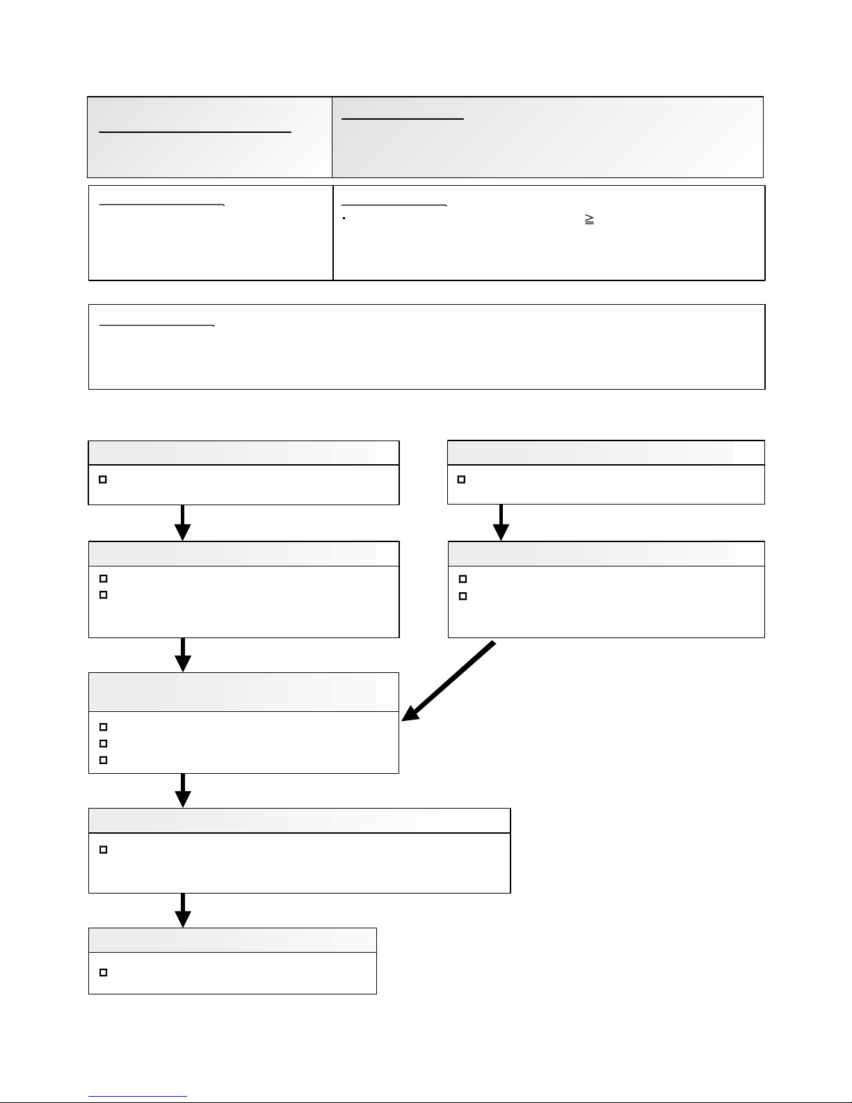
<Cooling operation>
OK
OK
OK
OK
:
OK
<Heating operation>
2. EEV defective, strainer clogged
3. Outdoor unit operation failure, foreign matter on heat exchanger
4. Discharge temperature thermistor failure
5. Insufficient refrigerant
Discharge temperature thermistor
"Protection stop by "discharge temperature 115°C during compressor
operation'''' generated 2 times within
24 hours.
Check Point 1 : Check if 3-way valve(gas side) is open.
Discharger thermistor characteristics check
(Check by disconnecting thermistor from PCB.)
* For the characteristics of the thermistor, refer to the "Service Parts Information 8".
Check Point 4 : Check the discharge thermistor
EEV open?
Strainer clogging check (before and after EEV, ACM
oil return)
Refer to "Service Parts Information 3, 4 "
Check Point 3 : Check the outdoor unit fan,heat exchanger
Check for foreign object at heat exchanger
Check if fan can be rotated by hand.
Motor check(PARTS INFORMATION 7)
Check Point 2 : Check the EEV, strainer
Check Point 5 : Check the refrigerant amount
Leak check
EEV open?
Strainer clogging check (before and after EEV, ACM
oil return)
Refer to "Service Parts Information 3, 4"
Check Point 2 : Check the EEV, strainer
If the 3-way valve(gas side) was closed, open the
3-way valve(gas side) and check operation.
02-27
Check Point 1 : Check if 3-way valve(liquid side) is open.
If the 3-way valve(liquid side) was closed, open the
3-way valve(liquid side) and check operation.
OK
1. 3-way valve not opened
Detective Actuators:
Detective details:
Forecast of Cause :
Trouble shooting 24
OUTDOOR UNIT Error Method:
Discharge Temp. Error
Indicate or Display:
Refer to error code table.
Page 58

Refer to error code table.
Compressor Temp. Error
OK
OK
OK
OK
1. 3-way valve not opened
2. EEV defective, strainer clogged
3. Outdoor unit operation failure, foreign matter on heat exchanger
4. Compressor temperature thermistor failure
5. Insufficient refrigerant
Compressor temperature thermistor
Compressor temperature thermistor characteristics check
(Check by disconnecting thermistor from PCB)
* For the characteristics of the thermistor, refer to the "Service Parts Information 8.
Check Point 4 : Check the compressor temperature thermistor
Check Point 3 : Outdoor unit fan, heat exchanger chek
Check for foreign object at heat exchanger
Check if fan can be rotated by hand.
Motor check(PARTS INFORMATION 7)
Check Point 5 : Check the refrigerant amount
Leak check
02-28
<Cooling operation>
OK
<Heating operation>
Check Point 1 : Check if 3-way valve(gas side) is open.
EEV open?
Strainer clogging check (before and after EEV, ACM
oil return)
Refer to "Service Parts Information 3, 4".
Check Point 2 : Check the EEV, strainer
EEV open?
Strainer clogging check (before and after EEV, ACM
oil return)
Refer to "Service Parts Information 3,4 ".
Check Point 2 : Check the EEV, strainer
If the 3-way valve(gas side) was closed, open the
3-way valve(gas side) and check operation.
Check Point 1 : Check if 3-way valve(liquid side) is open.
If the 3-way valve(liquid side) was closed, open the
3-way valve(liquid side) and check operation.
OK
"Protection stop by "compressor tempreture" 112°C during compressor
operation""generated 2 times within 24 hours
Trouble shooting 25
Indicate or Display:
Detective Actuators:
Detective details:
OUTDOOR UNIT Error Method:
Forecast of Cause :
Page 59

Refer to error code table.
Trouble shooting 26
OUTDOOR UNIT Error Method:
Low Pressure Error
Indicate or Display:
Detective Actuators:
Detective details:
Forecast of Cause :
OK
1. 3-way valve not opened 2. Outdoor unit ambient temperature too low
3. Outdoor unit fan operation defective, foreign matter at heat exchanger
4. EEV defective, strainer clogged 5. Solenoid valve defective
6. Low pressure sensor characteristics defective 7. Insufficient refrigerant
Suction pressure sensor
"Protection stop by suction pressure 0.05MPa continued for 5 minutes"
repeats 5 times within 2 hours.
No foreign oblect in air passage?
Heat exchange fins clogged
Fan rotates?
Outdoor unit fan motor check
Check Point 3 : Check the outdoor unit fan operation,
heat exchanger
Check Point 2 : Check the outdoor unit ambient temperature
Outdoor ambient temperature lower than operating range?
Outdoor unit EEV operation check
Strainer not clogged?
Check Point 4 : Check the outdoor unit EEV, strainer clogging
Indoor unit EEV operation check
Strainer not clogged?
strainer clogging
Suction pressure sensor characteristics check
* For the characteristics of the suction pressure sensor
(PARTS INFORMATION 9)
Check Point 6 : Check the suction pressure sensor
Check Point 7 : Check the refrigerant amount
Leak check
Check Point 5 : Check the solenoid valve (SV1)
Solenoid valve operation check
02-29
<Cooling operation>
<Heating operation>
Check Point 1 : Check if 3-way valve(gas side) is open.
If the 3-way valve(gas side) was closed, open the
3-way valve(gas side) and check operation.
Check Point 1 : Check if 3-way valve(liquid side) is open.
If the 3-way valve(liquid side) was closed, open the
3-way valve(liquid side) and check operation.
OK
OK
OK
OK
OK
OK
Refer to "Sevice Parts Information 3"
Page 60

Trouble shooting 27
Forecast of Cause:
OKOK
Indoor Unit - No Power
1. Power Supply failure 2. External cause
3. Electrical Components defective
Check Point 1 : Check Installation Condition
Isn’t the breaker down?
Check loose or removed connection cable.
>>If abnormal condition is found, correct it by referring
to Installation Manual or Data & Technical Manual.
Check Point 2 : Check external cause at Indoor and Outdoor (Voltage drop or Noise)
Instant drop ----- Check if there is a large load electric apparatus in the same circuit.
Momentary power failure ----- Check if there is a defective contact or leak current in
the power supply circuit.
Noise ----- Check if there is any equipment causing harmonic wave near electric line.
(Neon bulb or electric equipment that may cause harmonic wave)
Check the complete insulation of grounding.
02-30
2-3 TROUBLE SHOOTING WITH NO ERROR CODE
Check Point 3 : Check Electrical Components
YESYES
OK
NO
Check the voltage of power supply.
>> Check if AC198 - 264V appears at Outdoor Unit Terminal L - N.
Check Varistor in Filter PCB.
>> If Varistor is defective, there is a possibility of an abnormal power supply.
Check the correct power supply and replace Varistor.
Upon checking the normal power supply, replace Varistor.
If the symptom does not change by above Check 3, replace Main PCB.
OK
Check Fuse in Filter PCB.
>> If Fuse is open, check if the wiring between Terminal and Filter PCB
is loose, and replace Fuse.
Page 61

Trouble shooting 28
Forecast of Cause:
Check Point 3 : Check Electrical Components
OKOK
OKOK
YESYES
YESYES
OK
NO
Check Point 1 : Check Installation Condition
Outdoor Unit - No Power
1. Power Supply failure 2. External cause
3. Electrical Components defective
Isn’t the breaker down?
Check loose or removed connection cable.
>>If abnormal condition is found, correct it by referring
to Installation Manual or Data & Technical Manual.
Check Point 2 : Check external cause at Indoor and Outdoor (Voltage drop or Noise)
Instant drop ----- Check if there is a large load electric apparatus in the same circuit.
Momentary power failure ----- Check if there is a defective contact or leak current in the power supply circuit.
Noise ----- Check if there is any equipment causing harmonic wave near electric line.
(Neon bulb or electric equipment that may cause harmonic wave)
Check the complete insulation of grounding.
Check the voltage of power supply.
>> Check if AC198 - 264V appears at Outdoor Unit Terminal L - N.
Check Fuse in Main PCB.
>> If Fuse is open, check if the wiring between Terminal and Main PCB is loose,
and replace Fuse.
Check Active Filter Module and IPM. (PARTS INFORMATION 6 and 7)
>> If Active Filter Module or IPM is abnormal, replace it.
If the symptom does not change by above Check 3, replace Main PCB.
02-31
Page 62

Trouble shooting 29
Forecast of Cause:
Check Point 2 : Check external cause at Indoor and Outdoor (Voltage drop or Noise)
Check Point 1 : Check indoor and outdoor installation condition
Check Point 3 : Check Wired Remote Controller and Controller PCB
OK
OK
OKOK
No Operation (Power is ON)
1. Setting/ Connection failure 2. External cause
3. Electrical Component defective
Indoor Unit - Check incorrect wiring between Indoor Unit - Remote Control.
Or, check if there is an open cable connection.
Are these Indoor Unit, Outdoor Unit, and Remote Control suitable model numbers to connect?
>> If there is some abnormal condition, correct it by referring to Installation manual and
Data & Technical Manual.
Turn off Power and check/ correct followings.
Is there loose or removed communication line of Indoor Unit and Outdoor Unit?
Instant drop ----- Check if there is a large load electric apparatus in the same circuit.
Momentary power failure ----- Check if there is a defective contact or leak current in the power supply circuit.
Noise ----- Check if there is any equipment causing harmonic wave near electric line.
(Neon bulb or electric equipment that may cause harmonic wave)
Check the complete insulation of grounding.
>> If it is DC13V, Remote Control is failure. (Controller PCB is normal) >> Replace Remote Control
>> If it is DC 0V, Controller PCB is failure. (Check Remote Control once again) >> Replace Controller PCB
>> If the symptom does not change by above Check 1, 2, 3, replace Main PCB of Outdoor unit.
02-32
Check Voltage at CN14(ARTG30/36LHTA),CN140(ARTG45/54LHTA) of Controller PCB. (terminal 1-3)
(Power supply to Remote Control)
Page 63

Attention
Trouble shooting 30
Forecast of Cause:
Check Point 2 : Check Outdoor Unit Operation
Check Point 1 : Check Indoor Unit
Check Point 3 : Check Site Condition
Check Point 5 : Check Refrigeration Cycle
Check Point 4 :
Check Indoor/ Outdoor Installation Condition
Pipe (In) Pipe (Out)
Pipe (In) Pipe (Out)
OKOK
OKOK
OKOK
OKOK
MPa MPa
No Cooling / No Heating
1. Indoor Unit error 2. Outdoor Unit error
3. Effect by Surrounding environment
4. Connection Pipe / Connection Wire failure 5. Refrigeration cycle failure
Does Indoor Unit FAN run on HIGH FAN?
Is Air Filter dirty?
Is Heat Exchanger clogged?
Check if Energy save function is operated.
Check if Outdoor Unit is operating
Check any objects that obstruct the air flow route.
Check clogged Heat Exchanger.
Is the Valve open?
Is capacity of Indoor Unit fitted to Room size?
Any windows open? Or direct sunlight ?
Check connection pipe
(specified pipe length & Pipe diameter?)
Check any loose or removed communication line.
>> If there is an abnormal condition, correct it by
referring to Installation Manual or Data & Technical
Manual.
Check if Strainer is clogged (Refer to the figure at right).
Measure Gas Pressure and if there is a leakage, correct it.
>> When recharging the refrigerant, make sure to perform
vacuuming, and recharge the specified amount.
Check EEV (PARTS INFORMATION 3)
Check Compressor (PARTS INFORMATION 1,2)
Strainer normally does not have temperature difference
between inlet and outlet as shown in , but if there is a
difference like shown in , there is a possibility of inside
clogged. In this case, replace Strainer.
02-33
Page 64

Trouble shooting 31
Forecast of Cause :
Trouble shooting 32
Forecast of Cause:
OK
OK
OK
OK
OKOK
OKOK
OKOK
MPa MPa
Abnormal Noise
1. Abnormal installation (Indoor/ Outdoor)
2. Fan failure (Indoor/ Outdoor)
3. Compressor failure (Outdoor)
Diagnosis method when Abnormal Noise is occurred
Abnormal noise is coming from Indoor Unit.
(Check and correct followings)
Abnormal noise is coming from Outdoor Unit.
(Check and correct followings)
Is Fan broken or deformed?
Is the screw of Fan loose?
Is there any object which obstruct the Fan rotation?
Is Main Unit installed in stable condition?
Is the installation of Air suction grille and
front panel normal?
Is Fan broken or deformed?
Is the screw of Fan loose?
Is there any object which obstruct the Fan rotation?
Is Main Unit installed in stable condition?
Is Fan Guard installed normally?
Check if vibration noise by loose bolt or contact noise
of piping is happening.
Is Compressor locked?
>> Check Compressor (PARTS INFORMATION 1,2)
Water Leaking
1. Erroneous installation 2. Drain hose failure
Diagnosis method when water is spitting out.
Is the filter clogged?
Check Gas Pressure and correct it
if there was a gas leak.
Diagnosis method when water leak occurs
Is Drain Hose connection loose?
Is there a trap in Drain Hose?
Is Drain Hose clogged?
Is Main Unit installed in stable condition?
Is Main Unit broken or deformed at the time of
transportation or maintenance?
Is Fan rotating?
02-34
Page 65
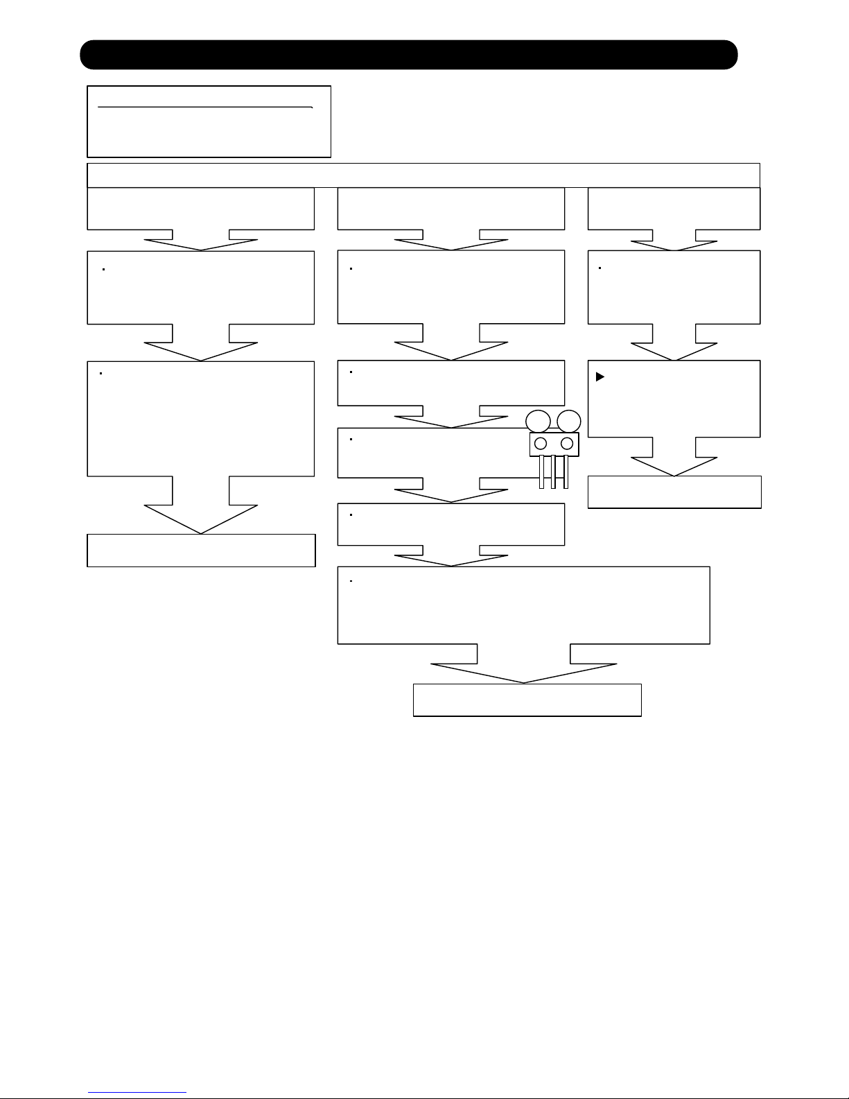
SERVICE PARTS INFORMATION 1
MPa MPa
Compressor
Diagnosis method of Compressor ( If Outdoor Unit LED displays Error, refer to Trouble shooting )
Does not start up
Is there open or loose connection
cable?
Check Main PCB, connection of
Compressor, and winding resistance.
(Refer to the next page).
Check Main PCB, connection of Compressor,and winding
resistance. (Refer to the next page).
>> If there is no failure, the defect of
Compressor is considered (Locked
compressor due to clogged dirt or
less oil)
Replace Compressor
Replace Compressor
Replace Compressor
Stops soon after starting up
Is there open or loose connection
cable?
Is Gas Pipe Valve open?
(Low Pressure is too low)
Check if Refrigerant is leaking.
(Recharge Refrigerant)
Check if Strainer is clogged.
(PARTS INFORMATION 3)
>> If there is no failure, the defect of Compressor can be
considered. (Compression part broken or valve defective.)
Abnormal noise
Defective Compressor
can be considered.
(due to inside dirt clogging
or broken component)
Check if vibration noise by
loose bolt or contact noise
of piping is happening.
02-35
2-4 SERVICE PARTS INFORMATION
Page 66

SERVICE PARTS INFORMATION 2
Check Point 1 : Check Connection
Check Point 2 : Check Winding Resistance
Check Point 3 : Replace Main PCB
U
V
W
Inverter Compressor
Check terminal connection of Compressor
(loose or incorrect wiring)
Check winding resistance of each terminal
If the resistance value is 0 or infinite, replace Compressor.
If the symptom does not change with above Check 1, 2, replace Main PCB.
02-36
Resistance Value :
0.432 ± 8% at 20°C
U
(RED)
V
(WHITE)
W
(BLACK)
IPM PCB
TM303TM304
TM305
RED
WHITE
BLACK
Compressor
Inverter PCB
Page 67

SERVICE PARTS INFORMATION 3
Check Point 2 : Check Coil of EEV
Yellow - Red
Orange - Red
Blue - Red
White - Red
Read wire
46 4
Resistance value
Check Point 1 : Check Connections
Check Point 5 : Check Opening and Closing Operation of Valve
Check Point 3 : Check Voltage from Main PCB.
Check Point 4 : Check Noise at start up
Pipe (In)
Pipe (Out)
Hi TEMP.
Pipe (In)
Hi TEMP.
Normal TEMP.
CLOSE
Example : Hot Gas
OPEN
Example : Hot Gas
Pipe (Out)
Hi TEMP.
Pipe (In) Pipe (Out)
Pipe (In) Pipe (Out)
Check Point 6 : Check Strainer
DC
at 68°F(20°C)
Outdoor unit Electronic Expansion Valve
( EEV )
Check connection of connector
( Loose connector or open cable )
Remove connector, check each winding
resistance of Coil.
If Resistance value is abnormal, replace EEV.
Remove Connector and check Voltage (DC12V)
If it does not appear, replace Main PCB.
Turn on Power and check operation noise.
If an abnormal noise does not show,
replace Main PCB.
When Valve is closed,
it has a temp. difference between Inlet and Outlet.
If it is open,
it has no temp. difference between Inlet and Outlet.
Strainer normally does not have temperature difference between inlet and outlet as shown in ,
but if there is a difference as shown in , there is a possibility of inside clogged. In this case, replace Strainer.
02-37
CN111
EXPANSION
VA
LVE COIL
EV
RED
BLUE
ORANGE
YELLOW
WHITE
1
2
3
4
5
6
Page 68

SERVICE PARTS INFORMATION 5
Check Point 1 : Check rotation of Fan
Outdoor unit fan motor
Rotate the fan by hand when operation is off.
(Check if fan is caught, dropped off or locked motor)
>>If Fan or Bearing is abnormal, replace it.
Check Point 2 : Check resistance of Outdoor Fan Motor 1 or 2
Refer to below. Circuit-test "Vm" and "GND" terminal.
(Vm: DC voltage, GND: Earth terminal)
>>If they are short-circuited (below 300 k ), replace Outdoor fan motor and Main PCB.
Pin number
(wire color)
Terminal function
(symbol)
1 (Red)
2
3 (Black)
4 (White)
5 (Yellow)
6 (Brown)
DC voltage (Vm)
No function
Earth terminal (GND)
Control voltage (Vcc)
Speed command (Vsp)
Feed back (FG)
SERVICE PARTS INFORMATION 4
Check Point 1 : Check rotation of Fan
Indoor unit fan motor
Rotate the fan by hand when operation is off.
(Check if fan is caught, dropped off or locked motor)
>>If Fan or Bearing is abnormal, replace it.
Check Point 2 : Check resistance of Indoor Fan Motor
Refer to below. Circuit-test "Vm" and "GND" terminal.
(Vm: DC voltage, GND: Earth terminal)
>>If they are short-circuited (below 300 k ), replace Indoor fan motor and Controller PCB.
Pin number
(wire color)
Terminal function
(symbol)
1 (Blue)
2 (Yellow)
3 (White)
4 (Black)
5
6 (Red)
Feed back (FG)
Speed command (Vsp)
Control voltage (Vcc)
Earth terminal (GND)
No function
DC voltage (Vm)
02-38
Page 69

SERVICE PARTS INFORMATION 6
Active filter module
02-39
Check Point 1 : Check Open or Short-circuit and Diode (D1)
Check Point 2 : Check the Output DC voltage (between P and N)
L2L1
P
N
+IN
Check the Output DC voltage (between P and N) of compressor stopping and operating.
If it is abnormal,replace ACTIVE FILTER MODULE
Remove connector, check the open or short-circuit and the diode in the module
>> If the output voltage of compressor operating is less than the output voltage of compressor stopping,
Active Filter Module is detective. >> Replace Active Filter Module
Terminal
Resistance value
L2
L1
L1,L2
P
P
Control Box
N
N
(+IN)
(+IN)
( IN)
( IN)
Tester(+) Tester(-)
Check the open or short-circuit
L2
P
P
N
L2
L2
Check the diode
0
360k
720k
1.69M /
20%
+
-
360k
20%
+
-
20%
+
-
(Ref. value 1)
1.88M
(Ref. value 2)
1.40M /
(Ref. value 1)
2.28M
(Ref. value 2)
Terminal
Resistance value
Tester(+) Tester(-)
1.32M /
(Ref. value 1)
1.50M
(Ref. value 2)
1.40M /
(Ref. value 1)
1.51M
(Ref. value 2)
Ref. value 1
Specifications for Multimeter
Manufacturer : HIOKI
Model name : 3804
Power source : DC9V.
Ref. value 2
Specifications for Multimeter
Manufacturer : YOKOGAWA
Model name : 7534
Power source : DC3V.
-IN
Page 70

SERVICE PARTS INFORMATION 7
IPM
(Mounted on Transistor PCB)
02-39
Check Point 1
Check Point 2
Terminal
Resistance value
Tester(+) Tester(-)
Disconnect the connection wires between the Transistor
PCB - Capacitor PCB and Transistor PCB - Inverter
Compressor.
Set the tester to the "Resistance" mode, and measure
the resistance between the following terminals.
Set the tester to the "Diode" mode, and measure the voltage value between the following terminals.
Judge the result of as follows:
Judge the result of as follows:
TM301 (P) - TM305(U) / TM304(V) / TM303(W)
TM302 (N) - TM305(U) / TM304(V) / TM303(W)
P
P
P
U
V
W
N
N
N
U
V
W
U
V
W
P
P
P
U
V
W
N
N
N
Over 2k
(Including )
Over 2k
(Including )
Over 20k
(Including )
Terminal
Tester display
Tester(+) Tester(-)
P
P
P
U
V
W
N
N
N
U
V
W
U
V
W
P
P
P
U
V
W
N
N
N
0.3V 0.7V
Page 71

SERVICE PARTS INFORMATION 8
Thermistor
02-41
Check Point : Check Thermistor resistance value
Remove connector and check Thermistor resistance value.
Temperature
[°C]
Resistance Value [ k ]
Thermistor A Thermistor B Thermistor C Thermistor D
- 20
- 10
- 5
0
5
10
15
20
25
30
40
50
60
70
80
90
100
110
120
---
---
---
168.6
129.8
100.9
79.1
62.6
49.8
40.0
26.3
17.8
12.3
8.7
6.3
4.6
3.4
2.6
2.0
---
27.8
21.0
16.1
12.4
9.6
7.6
6.0
4.8
3.8
2.5
1.7
1.2
---
---
---
---
---
---
105.4
58.2
44.0
33.6
25.9
20.2
15.8
12.5
10.0
8.0
5.3
3.6
---
---
---
---
---
---
---
---
27.4
20.7
15.8
12.2
9.5
7.5
5.9
4.7
3.8
2.5
1.7
1.2
0.8
0.6
0.4
0.3
---
---
Applicable
Thermistors
Discharge temp. TH
Comprssor temp. TH
Outdoor temp. TH Heat sink temp. THHeat exchanger. TH
Page 72

SERVICE PARTS INFORMATION 9
Discharge Pressure Sensor
Suction Pressure Sensor
Check Point : Check Voltage from Main PCB
DC
With the connector connected to the PCB, measure the voltage between CN91:3-4
of the Main PCB.
1. Discharge Pressure Sensor
Characteristics of pressure sensor
4.5
5.0
0.5
0
Output [DCV]
Pressure [MPa]
DC
Check Point : Check Voltage from Main PCB
DC
With the connector connected to the PCB, measure the voltage between CN92:2-3
of the Main PCB.
2. Suction Pressure Sensor
Characteristics of pressure sensor
3.5
1.7
0.5
0
Output [DCV]
Pressure [MPa]
DC
02-42
1 1
3
3
WHITE
PRESSURE
SENSOR
(HIGH)
BLACK
2 2
RED
PS
1 1
3 3
WHITE
PRESSURE
SENSOR
(LOW)
BLACK
2 2
RED
PS
CN91
4
4
2.5
2.5
CN92
0.85
2.0
Page 73
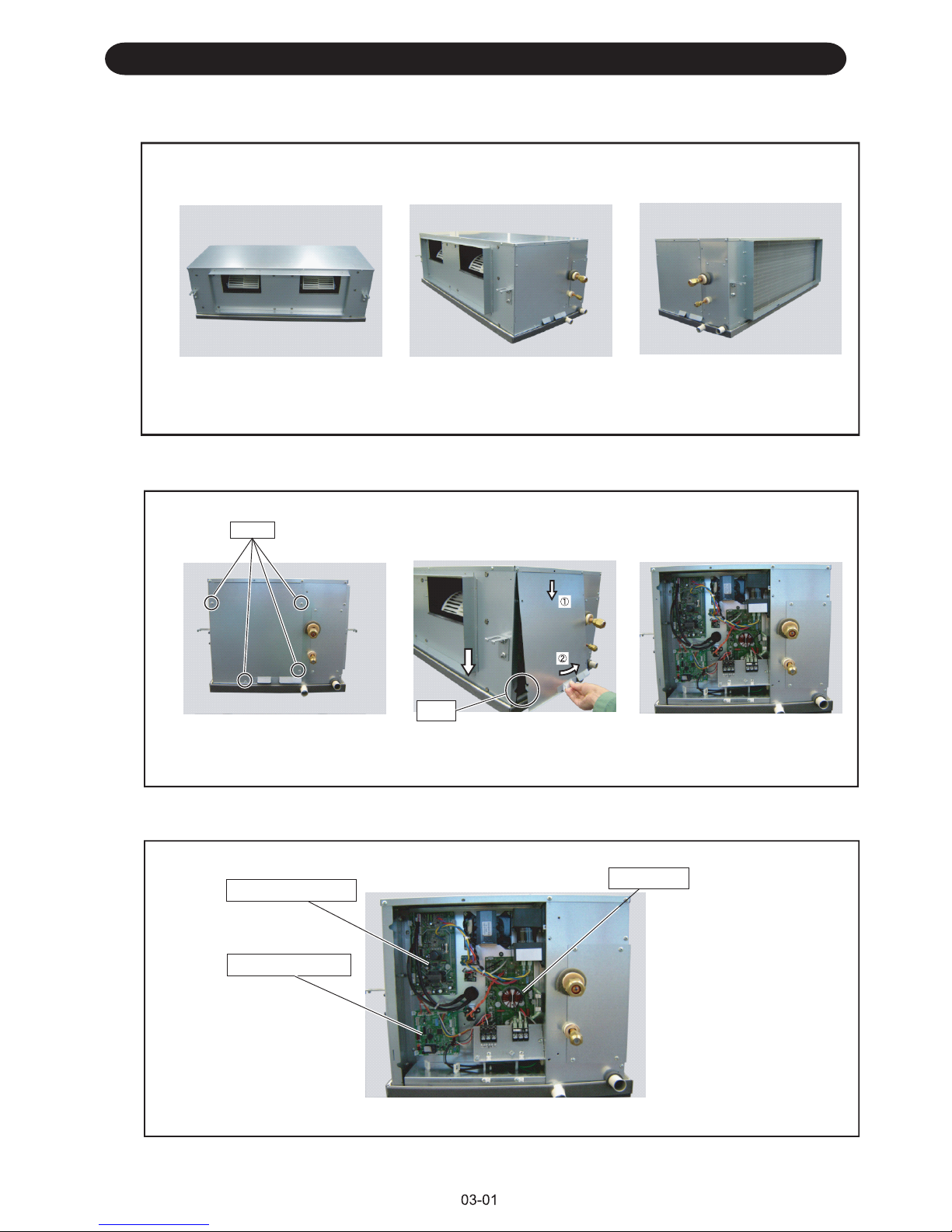
1. Appearance
2. CONTROL BOX COVER removal
3. POWER SUPPLY PCB, CONTROLLER PCB and FILTER PCB removal
DISASSEMBLY PROCESS
POWER SUPPLY PCB
screw
1) Remove the mounting screws
(4 places).
Hook
2) Remove the control box cover.
CONTROLLER PCB
FILTER PCB
FRONTVIEW
SIDEVIEW
MODEL : ARTG45 / 54LHTA
BACKVIEW
Page 74

3-1. POWER SUPPLY PCB removal
1) Remove the connectors and each wires.
2) Remove the locking spacers(4 places).
locking spacers
3-2. CONTROLLER PCB removal
1) Remove the connectors and each wires.
2) Remove the earth screw
and locking spacers(4 places).
locking spacers
3-3. FILTER PCB removal
1) Remove the connectors,
each wires and
terminal wire (black,white,red).
3) Remove the terminal bracket.
earth screw
2) Remove the mounting screws
(2 places).
earth
screw
4) Remove the earth screw
and locking spacers(5 places).
locking spacers
Hook
screw
Page 75

4. FAN MOTOR removal
03-03
1) Remove the mounting screws(13 places).
screw
screw
screw
screw
2) Remove the PANEL TOP ASSY.
screw
screw
4) Remove the mounting screws(4 places).
6) Loosen the MOTOR SHAFT screw. 7) Slide the left with the SIROCCO FAN and CASING.
5) Pull the CASING.
Tape
Reuse the tape.
MOTOR SHAFT
3) Peel off the tapes.
Page 76

03-04
Note at the installation.
5. SIROCCO FAN removal
1) Remove the screws(4 places).
screw
hook
2) Take it out the SIROCCO FAN.
■Insert SIROCCO FAN and MOTOR SHAFT reference D cutting position.
Please insert it till a SIROCCO FAN stop.
■Please install it so that a motor band touches rubber.
2) Tighten the screw.
1) Insert it till a SIROCCO FAN stop.
9) Loosen the screw.
8) Take out the SIROCCO FAN
and CASING.
screw
hook
Unlock the point.
MOTOR SHAFT
NGOK
Page 77

6. THERMISTOR removal
6-1 PIPE THERMISTOR
6-2 ROOM THRMISTOR
1) Remove the mounting
screws(4 places)
3) Remove the
THERMISTOR SPRING.
Remove the THERMISTOR.
4) Remove the
THERMISTOR.
screw
03-05
7. DRAIN PAN removal
screw
2) Remove the PIPE PANEL.
1) Remove the mounting
screws(2 places)
2) Remove the DRAIN PAN.
Attention!!
When remove the screw,
please affix and remove the hand.
Page 78

1116,Suenaga,Takatsu-ku,Kawasaki 213-8502,Japan
Mar. 2011 Printed in Japan
 Loading...