

Fujitsu AB*G45LRTA, AR*G45LHTA, AB*G54LRTA, AU*G45LRLA, AU*G54LRLA Design & Technical Manual
...Page 1
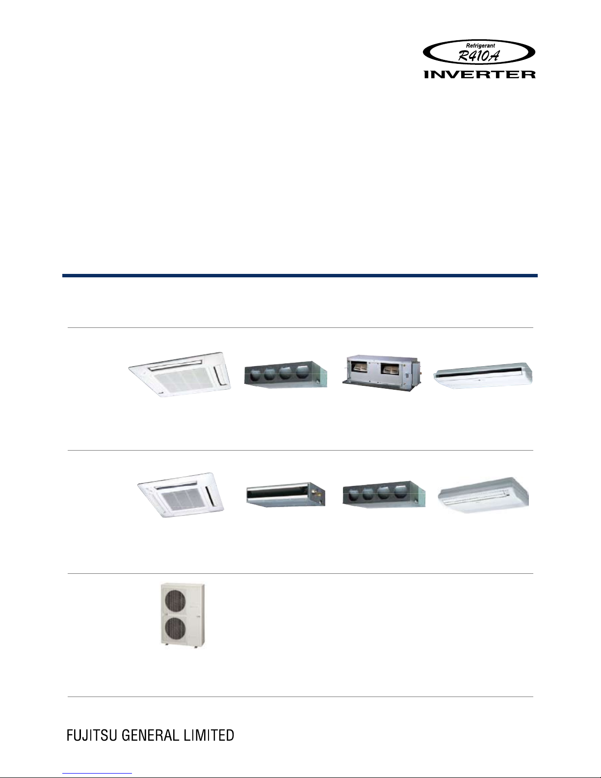
AIR CONDITIONER
3 phase type
Single / Simultaneous multi system
SINGLE INDOOR
SIMULTANEOUS MULTI INDOOR
OUTDOOR
DESIGN & TECHNICAL MANUAL
DTR_SSM001E_03
2013.02.22
AUG36LRLA
AU
G45LRLA
AU
G54LRLA
AR
G36LMLA
AR
G45LMLA
AR
G45LHTA
AR
G54LHTA
AB
G36LRTA
AB
G45LRTA
AB
G54LRTA
AUG18LVLB
×
2
AU
G22LVLA
×
2
AU
G24LVLA
×
2
AU
G18LVLB × 3
AR
G22LMLA
×
2
AR
G24LMLA
×
2
AR
G18LLTB
×
2
AR
G18LLTB
×
3
AB
G18LVTB
×
2
AB
G22LVTA
×
2
AB
G24LVTA
×
2
AB
G18LVTB × 3
AOG36LATT
AO
G45LATT
AO
G54LATT
Page 2

1. GENERAL INFORMATION
2. INDOOR UNIT (SINGLE)
3. INDOOR UNIT (SIMULTANEOUS MULTI)
4. OUTDOOR UNIT
5. SYSTEM DESIGN
6. OPTIONAL PARTS
CONTENTS
Page 3

1. GENERAL INFORMATION
AIR CONDITIONER
3 phase type
Single / Simultaneous multi system
DTR_SSM001E_03--CHAPTER01
2013.02.22
Page 4

CONTENTS
1. GENERAL INFORMATION
1. FEATURES OF SYSTEM
··············································································01-01
1-1. PERFORMANCE AND ENERGY SAVING
·····················································01-01
1-2. EASY INSTALLATION
···················································································01-03
1-3. QUIET OPERATION
·······················································································01- 04
1-4. SIMULTANEOUS MULTI SYSTEM
································································01-05
1-5. CONTROL SYSTEM
·······················································································01- 06
2. MODEL LINE UP
····························································································01- 09
2-1. INDOOR UNITS
······························································································01-09
2-2. OUTDOOR UNIT
···························································································· 01-10
2-3. CONTROLLER
······························································································· 01-11
2-4. BRANCH PIPES
····························································································· 01-12
2-5. CASSETTE GRILLE
······················································································· 01-13
2-6. OTHERS (optional parts)
·············································································· 01-14
Page 5
- (01-01) -
GENER AL
INFORMATION
GENER AL
INFORMATION
FEATURES OF SYSTEM1.
PERFORMANCE AND ENERGY SAVING1-1.
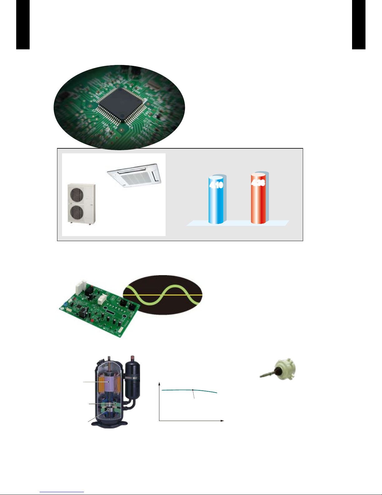
HIGH PERFORMANCE AND TOP CLASS ENERGY SAVING
(SINGLE SYSTEM)
Both high performance and top class
energy saving achieved by adoption of
DC inverter.
Operating cost suppressed while
maintaining comfort.
EER
(Cooling)
COP
(Heating)
4.38
4.10
4.38
4.10
By 3-phase 36,000BTU with cassette type indoor unit.
AOG3 6LATT
AUG36LRLA
SINE WAVE DC INVERTER CONTROL
High efciency operation is realized by using a sine wave DC inverter control.
DC TWIN ROTARY COMPRESSOR
Compre ssor
effi ciency
High
High
Compre ssor ca pacit y
DC Twin Rota ry com pres sor
DC twin rotary compressor
Efficiency in all load regions is good.
Especially good performance from low to
medium at normal operation.
High efficiency
compressor motor
Optimized refrigerant
flow design
Highly accurate parts
DC FAN MOTOR
Miniaturized, low noise,
high efciency, multi-stage
DC fan motor is mounted.
Page 6
- (01-02) -
GENER AL
INFORMATION
GENER AL
INFORMATION
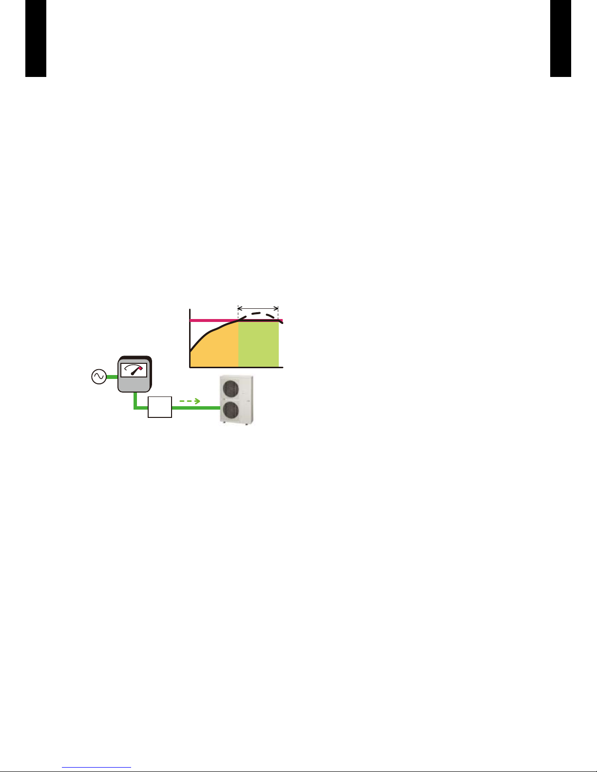
PEAK CUT FUNCTION (OPTIONAL PARTS: UTY-XWZXZ2)
Suppresses maximum capacity and performs energy-saving operation and can prevent breaker
tripping.
This function performs operation by setting a peak current value and reducing the power
consumption.
* Performance drops by reducing the power consumption preferentially.
Level 1 ... Performs operation which suppresses the power consumption to almost 0% by stopping
the compressor.
Level 2 ... Performs operation which suppresses the power consumption to 50% of the rated
power consumption value.
Level 3 ... Performs operation which suppresses the power consumption to 75% of the rated
power consumption value.
Level 4 ... Performs operation which suppresses the power consumption to the rated power
consumption value (100%).
W
Capacity
Time
Setting level
Peak cut
Control
device
Signal input
Page 7
- (01-03) -
GENER AL
INFORMATION
GENER AL
INFORMATION
EASY INSTALLATION1-2.
HIGH INSTALL ABILITY LONG PIPING CORRESPONDENCE
(SINGLE SYSTEM)
Pre-charge
length
30m
Max pipe
length
75m
Max height
difference
30m
Long piping provides an outdoor unit and indoor unit
layout margin.
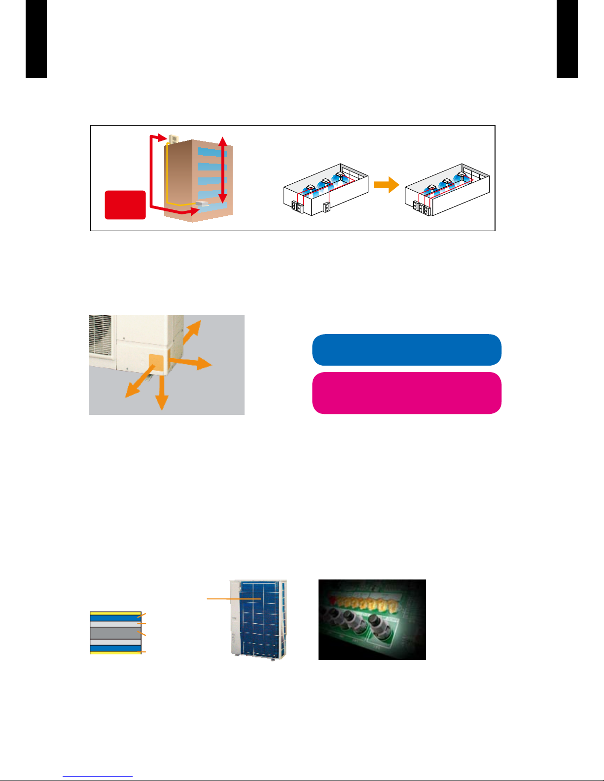
4-DIRECTIONS PIPING
CONNECTION
Four directions piping connection is
possible. The perfect route can be selected
according to the installation.
LOW OUTDOOR
AIR TEMPERATURE
CORRESPONDENCE
Both cooling and heating operations can be
performed when the outdoor air temperature is
low.
EXTERNAL OUTPUT (OPTION)
Compressor status output
z
This output indicates the outdoor unit
operation status's On / Off.
Error status output
z
This output indicates the outdoor unit and
connected indoor unit's Normal / Error.
BLUE FIN HEAT EXCHANGER
Corrosion-resistance of the heat exchanger
even in coastal areas has been improved
by blue n treatment of the outdoor unit
heat exchanger.
Blue n heat exchanger
Cobalt Blue protection
Standard chrom ate protection
Aluminium base material
Hydrophilic coating
SERVICE, MAINTENANCE
"Error display" and "Operating information" can •
be explained by LED display.
Pump down operation can be performed by •
one button when refrigerant recovery.
Rear
Front
Lateral
Bottom
Cooling
-15 ºC
Heating
Dry-b ulb
-15 ºC
Wet-bulb
-20 ºC
Page 8

- (01-04) -
GENER AL
INFORMATION
GENER AL
INFORMATION
QUIET OPERATION1-3.
LOW NOISE FUNCTION (OPTIONAL PARTS: UTY-XWZXZ2)
Suppresses operating sound.
This function suppresses the outdoor unit noise value to the following 2 level.
* Performance may drop depending on the outside air temperature condition, etc.
Level 1 ... Rated noise value -2dB
Level 2 ... Rated noise value -4dB
100%
Air
conditioning
load factor
Capacity
Down
Operation
sound
Low noise mode
0
0
Heat load
(time)
Page 9

- (01-05) -
GENER AL
INFORMATION
GENER AL
INFORMATION
SIMULTANEOUS MULTI SYSTEM 1-4.
IDEAL COMFORTABLE AIR FLOW DISTRIBUTION
Can support various installation
scenes from ofce to commercial
space by same place multi
connection of up to 3 units.
Indoor units distributed layout according to the shape and number
of people and lighting conditions of the room even on wide oors
and atypical oors. Ideal comfortable air ow distribution can be
realized.
Installation according to oor
layout
Installation according to
lighting conditions
Installation according to
layout and lighting conditions
ALL DC
ALL DC saves energy throughout the year
z
By making all the motors DC, electricity loss is decreased and power consumption
is substantially reduced. In addition, fan motor high speed rotation is increased and
annual power consumption amount is saved by increasing the airow.
Page 10
- (01-06) -
GENER AL
INFORMATION
GENER AL
INFORMATION
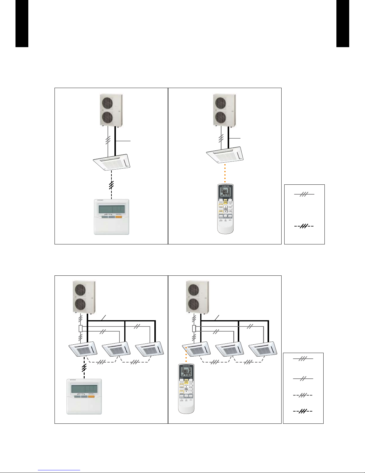
CONTROL SYSTEM1-5.
1-REMOTE CONTROLLER CONTROL
This is the most basic system. Wired type or wireless type remote controller can be selected.
Single system
z
Refriger ant pipe
Wired R.C.
Indoor uni t
Wireless R.C.
Refriger ant pipe
Transmission/
Power supply cable
Indoor uni t
Remote controller cable
* When using a wireless type remote controller, install IR Receiver unit to the indoor units.
(Cassette type, Duct type)
Simultaneous multi system
z
Refrigerant pipe
Indoor uni t 0
(Primary)
Indoor uni t 1
(Secondary)
Indoor uni t 2
(Secondary)
Indoor uni t 1
(Secondary)
Indoor uni t 2
(Secondary)
Wired R.C.
Bus wire
Indoor uni t 0
(Primary)
Refrigerant pipe
Wireless R.C.
Transmission/
Power supply cable
Power supply cable
Remote controller cable
* When using a wireless type remote controller, install IR Receiver unit to the indoor units.
(Slim duct type, Duct type)
* In simultaneous multi connection, the timer and 10°C HEAT functions by using the wireless remote controller cannot
be used.
Page 11
- (01-07) -
GENER AL
INFORMATION
GENER AL
INFORMATION
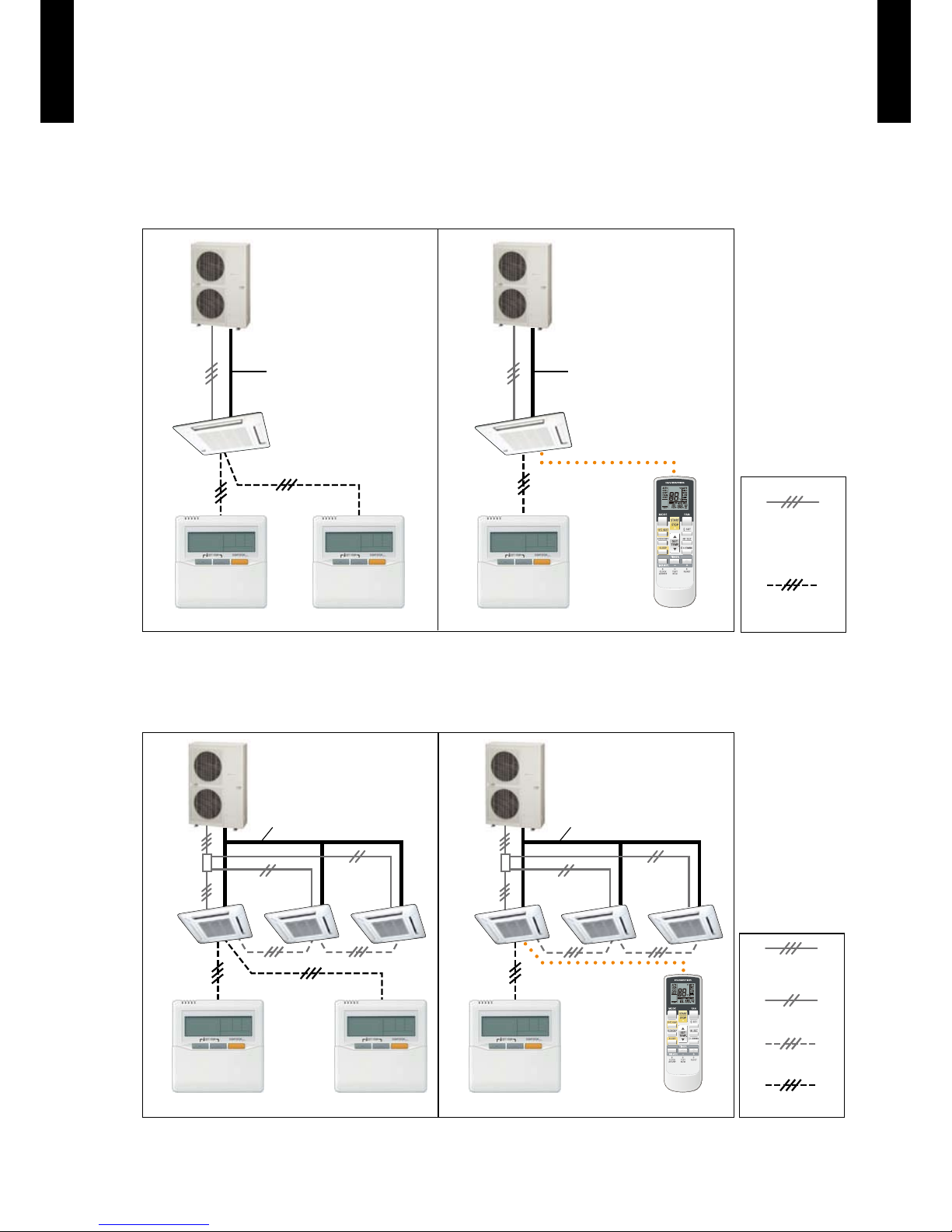
2-REMOTE CONTROLLERS CONTROL
Control locally and from a remote point is possible using 2-remote controllers.
Single system
z
Refriger ant pipe
Wired R.C. Wired R.C.
Indoor uni t
(Primary) (Primary)(Secondary)
Refriger ant pipe
Wired R.C.
Indoor uni t
Wireless R.C.
Transmission/
Power supply cable
Remote controller cable
* For 2 wired-type remote controllers, specify a primary and a secondar y remote controller.
*
The timer and 10°C HEAT (Wireless R.C. only) functions of the remote controller specied as the secondary cannot be used.
* When using a wireless type remote controller, install IR Receiver unit to the indoor units.
(Cassette type, Duct type)
Simultaneous multi system
z
Refrigerant pipeRefrigerant pipe
(Primary) (Primary)
(Secondary)
Wired R.C. Wired R.C. Wired R.C.
Wireless R.C.
Bus wire
Transmission/
Power supply cable
Power supply cable
Remote controller cable
Indoor uni t 0
(Primary)
Indoor uni t 1
(Secondary)
Indoor uni t 2
(Secondary)
Indoor uni t 0
(Primary)
Indoor uni t 1
(Secondary)
Indoor uni t 2
(Secondary)
* For 2 wired-type remote controllers, specify a primary and a secondar y remote controller.
*
The timer and 10°C HEAT (Wireless R.C. only) functions of the remote controller specied as the secondary cannot be used.
* In simultaneous multi connection, the timer and 10°C HEAT functions by using the wireless remote controller cannot
be used.
* When using a wireless type remote controller, install IR Receiver unit to the indoor units.
(Slim duct type, Duct type)
Page 12
- (01-08) -
GENER AL
INFORMATION
GENER AL
INFORMATION
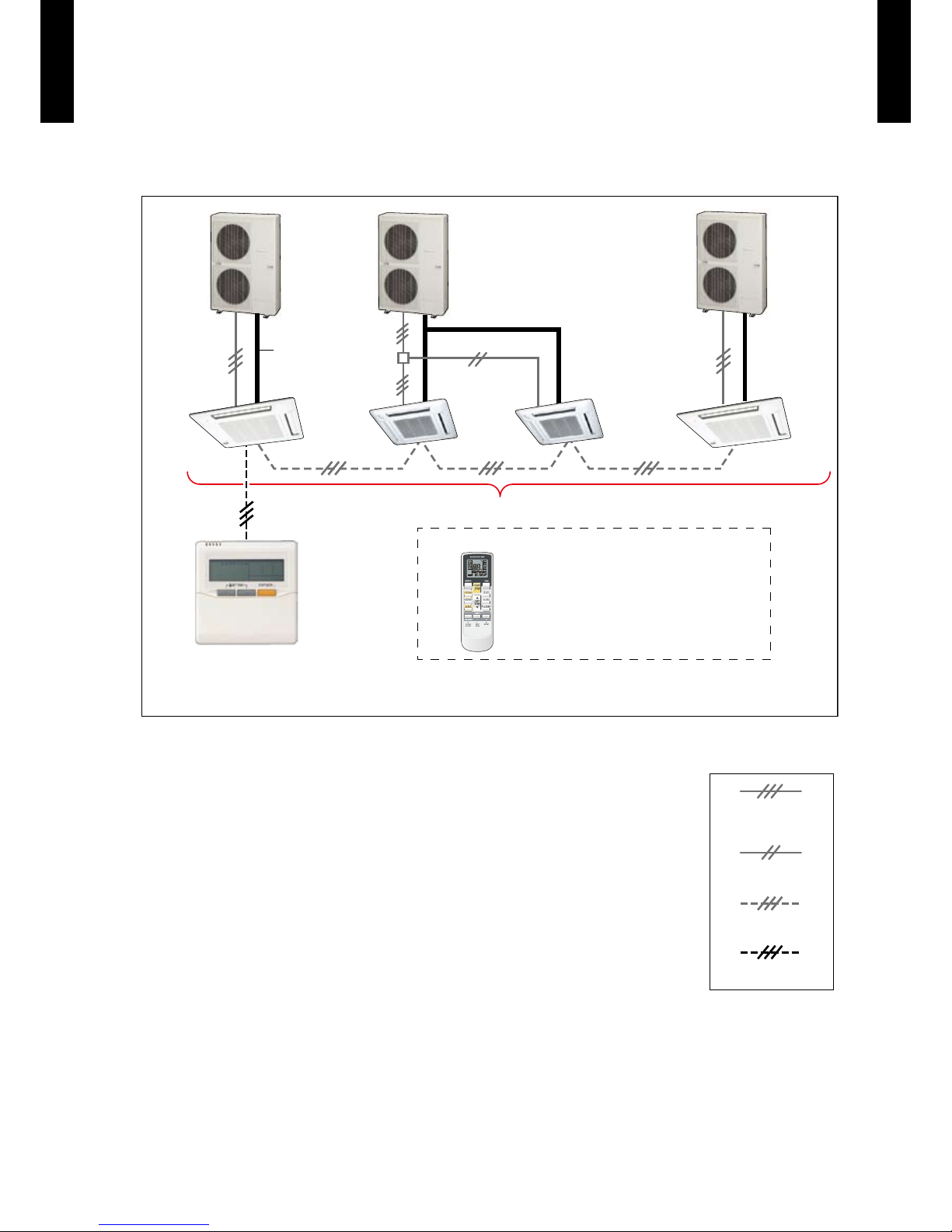
GROUP CONTROL
Max 16 indoor units are simultaneously controlled with a wired remote controller.
Refrigerant
pipe
Refrigerant pipe
Wired R.C.
OR
Max 16 indoor units
Indoor unit 0
Indoor unit 1
(Primary)
Indoor unit 2
(Secondary)
Indoor unit 15
Set the remote control address using DIP switch or Rotary switch (High static pressure duct type only) on
indoor unit circuit board.
Wireless R.C.
* In simultaneous control,
the timer and 10°C HEAT function by using
the wireless remote controller
cannot be used.
Bus wire
Transmission/
Power supply cable
Power supply cable
Remote controller cable
* In the group connection of different models, the functions which can be set by using the wired remote controller are
limited.
Page 13
- (01-09) -
GENER AL
INFORMATION
GENER AL
INFORMATION
MODEL LINE UP2.
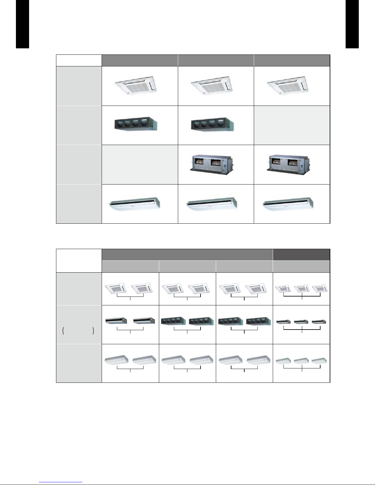
INDOOR UNITS2-1.
SINGLE SYSTEM
36 model 45 model 54 model
CASSETTE
AUG36LRLA AU
G45LRLA
AU
G54LRLA
DUCT
AR
G36LMLA
AR
G45LMLA
DUCT
(High static pressure)
AR
G4 5LH TA
AR
G5 4LH TA
CEILING
AB
G3 6LR TA
AB
G4 5LR TA
AB
G5 4LR TA
SIMULTANEOUS MULTI SYSTEM
TWIN TRIPLE
18 model x2 22 model x2 24 model x2 18 model x3
COMPACT
CASSETTE
AUG18LVLB x 2 AUG22LVLA x 2 AUG24LVLA x 2 AU
G18LVLB x 3
DUCT
18: Slim duct
22, 24: Duct
AR
G18LLTB x 2
AR
G22LM LA x 2
AR
G24LML A x 2
AR
G18LLTB x 3
FLOOR /
CEILING
AB
G18LVTB x 2
AB
G22LVTA x 2
AB
G24LVTA x 2
AB
G18LVTB x 2
Note :
The combination other than above cannot be per formed.
(For example, different indoor type combination such as AU
G2 2LV LA
+ AR
G22LMLA
cannot be performed.)
Page 14
- (01-10) -
GENER AL
INFORMATION
GENER AL
INFORMATION
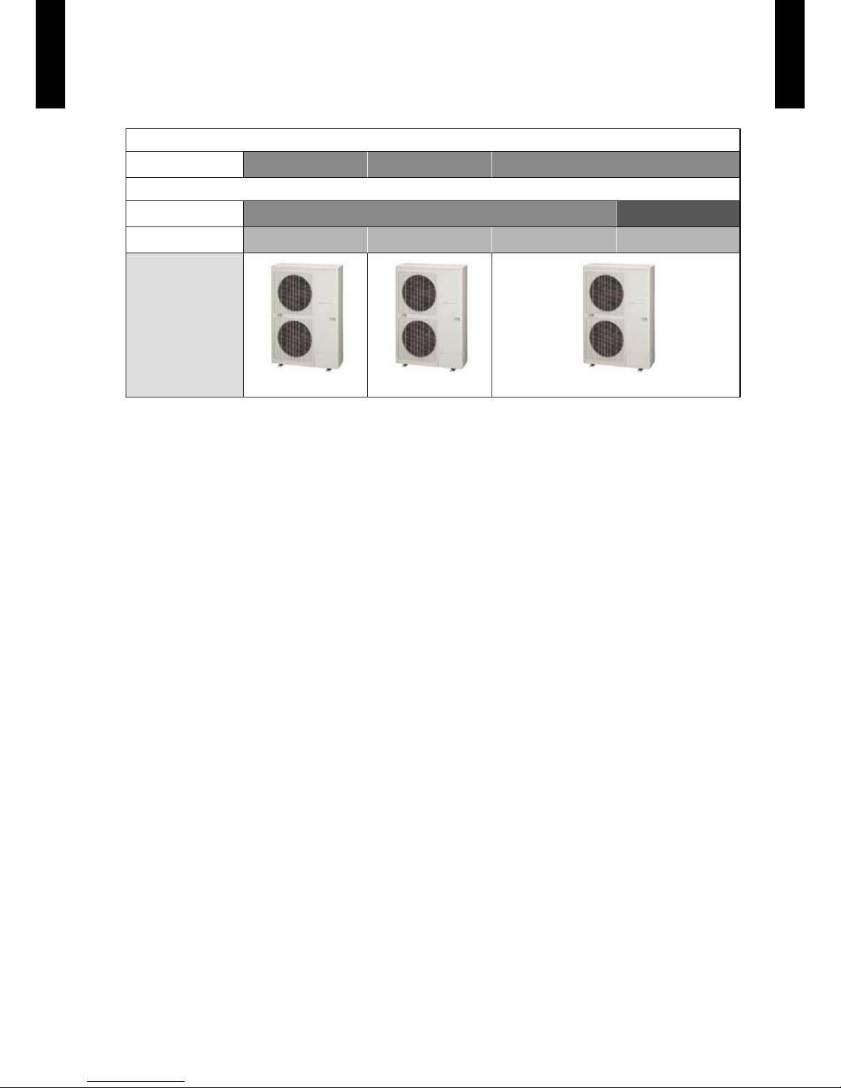
OUTDOOR UNIT2-2.
SINGLE SYSTEM
INDOOR UNIT 36 model 45 model 54 model
SIMULTANEOUS MULTI SYSTEM
CONNECTION TYPE Twi n Tri ple
INDOOR UNIT 18 model x 2 22 model x 2 24 model x 2 18 model x 3
Outdoor Unit
AOG3 6LAT T AOG4 5LATT AOG5 4LAT T
Page 15
- (01-11) -
GENER AL
INFORMATION
GENER AL
INFORMATION
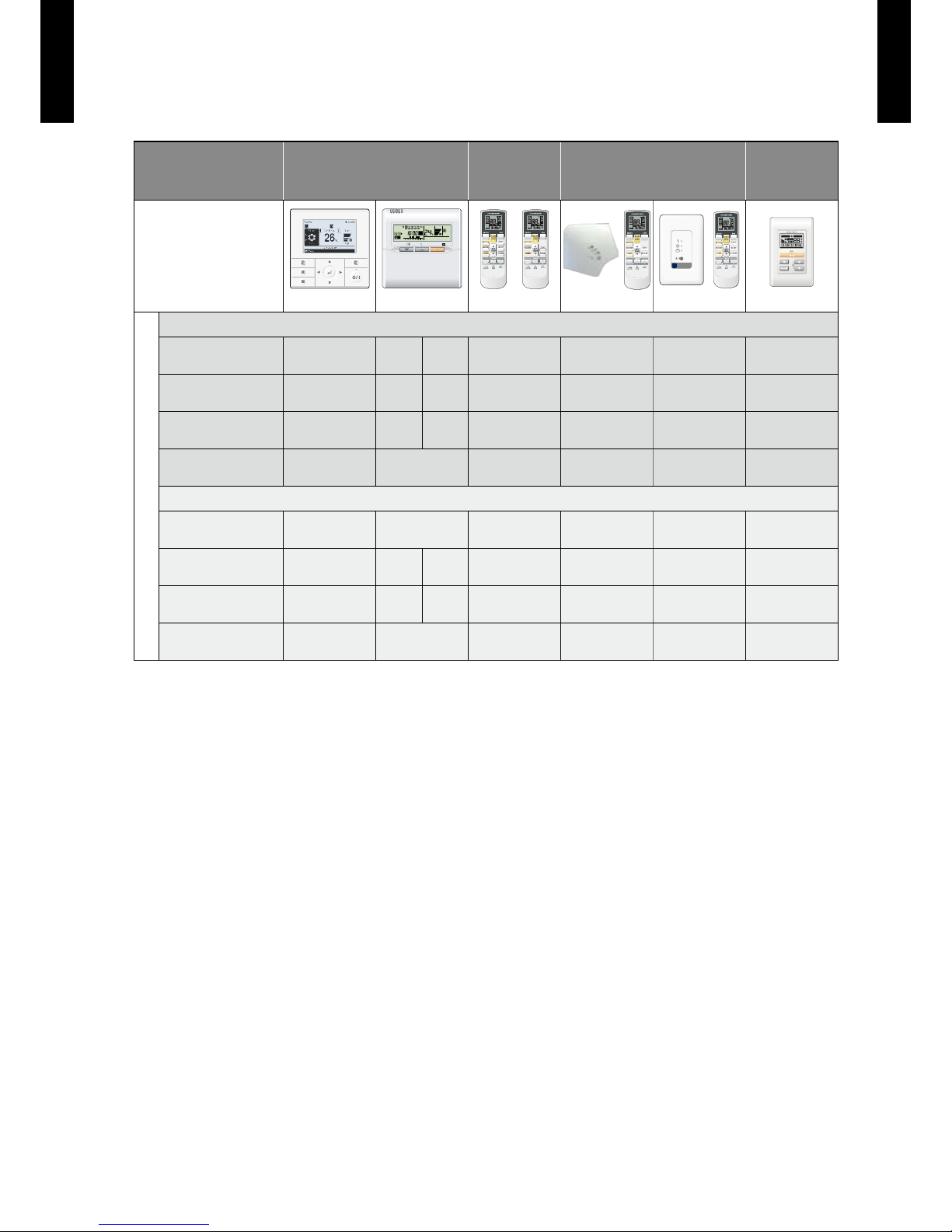
CONTROLLER2-3.
REMOTE
CONTROLLER TYPE
Wired Remote Controller
Wireless
Remote
Controller
IR Receiver Unit
Simple
Remote
Controller
Note;
z
: Accessory
:
Optional Parts
―
:
It is not possible to
connect it.
UT Y-RVNM
SET TEMP.
START/STOP
UT Y-RNNM
UTY - LRHA2 UTY - LRHM
UT Y-RSNM
INDOOR UNITS
SINGLE SYSTEM
CASSETTE
z
―
―
DUCT
z
― ―
HIGH STATIC
PRESSURE DUCT
z
― ― ―
CEILING
z
― ―
SIMULTANEOUS MULTI SYSTEM
COMPACT
CASSETTE
z
― ―
SLIM DUCT
z
― ―
DUCT
z
― ―
FLOOR / CEILING
z
― ―
Page 16

- (01-12) -
GENER AL
INFORMATION
GENER AL
INFORMATION
BRANCH PIPES2-4.
Twin connection type
Model : UTP - SX236
Liquid pipe
Ø6.35
Ø6.35
Ø9.52
Ø12.70
Gas pipe
Ø12.70
Ø12.70
Ø15.88
Ø19.05
Twin connection type
Model : UTP - SX254
Liquid pipe
Ø12.70
Ø9.52
Ø9.52
Ø9.52
Gas pipe
Ø19.05
Ø15.88
Ø15.88
Ø15.88
Adapter
Ø6.35
Ø9.52
Triple connection type
Model : UTP - SX354
Liquid pipe
Ø12.70
Ø9.52
Ø6.35
Gas pipe
Ø19.05
Ø15.88
Ø12.70
Cable tie
Page 17
- (01-13) -
GENER AL
INFORMATION
GENER AL
INFORMATION
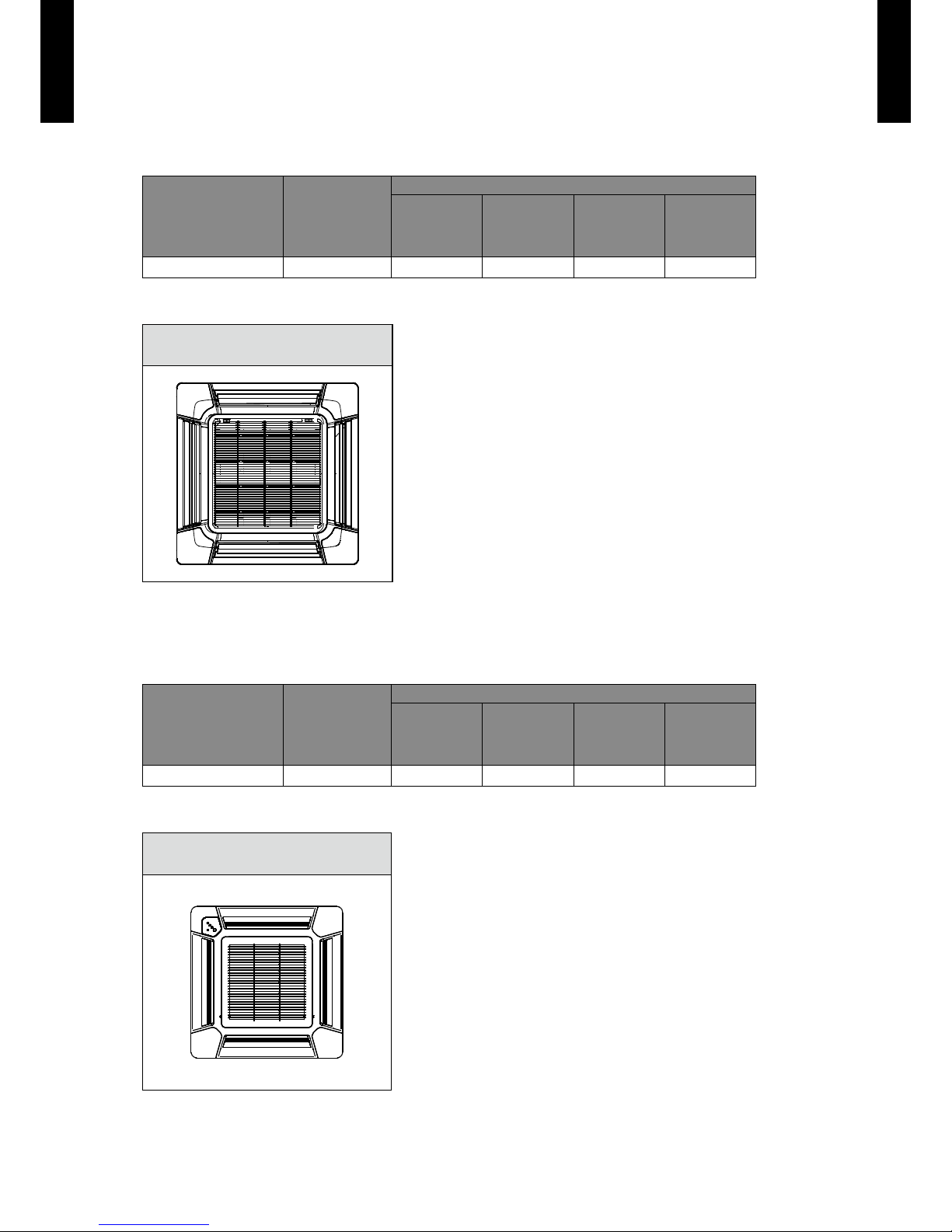
CASSETTE GRILLE2-5.
SINGLE SYSTEM
TYPE MODEL
INDOOR UNITS
CASSETTE DUCT
HIGH STATIC
PRESSURE
DUCT
CEILING
Cassette grille UTG-UG
A-W
― ― ―
Parts
z
Cassette grille
Model: UTG-UGA-W
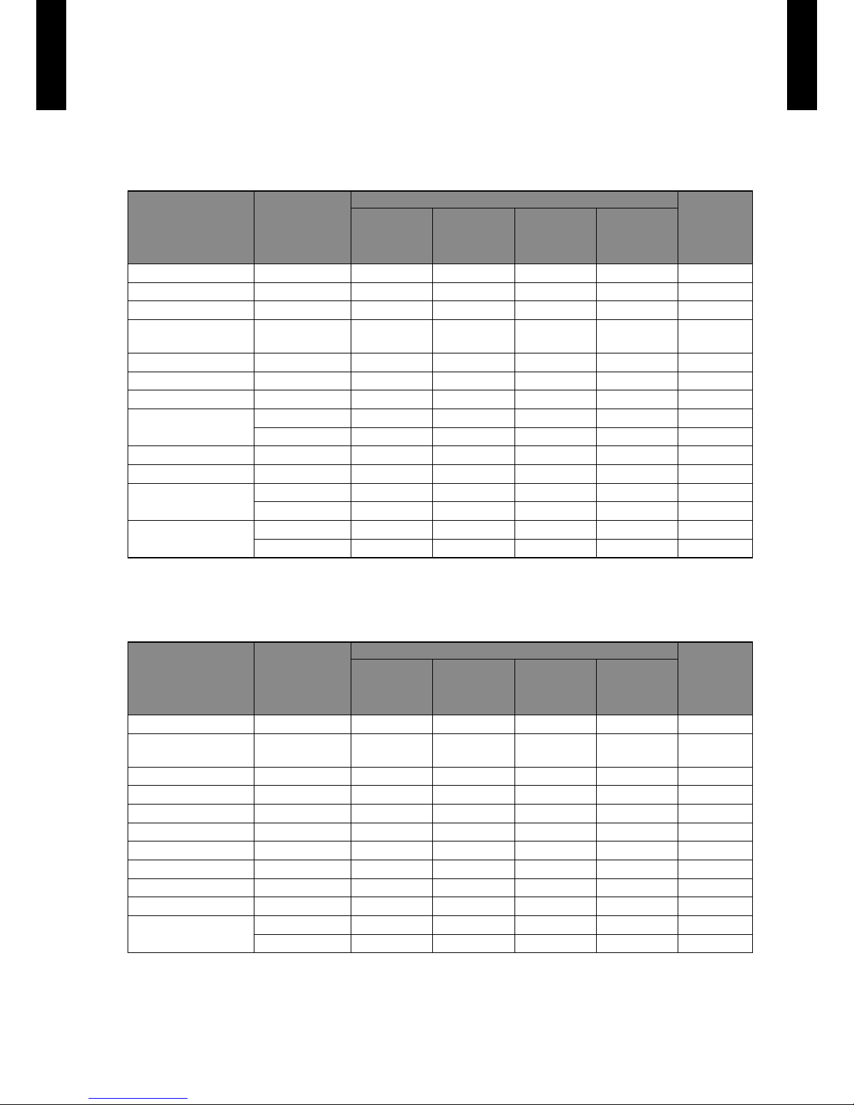
SIMULTANEOUS MULTI SYSTEM
TYPE MODEL
INDOOR UNITS
COMPACT
CASSETTE
SLIM
DUCT
DUCT
FLOOR /
CEILING
Cassette grille UTG- UF
D-W
― ― ―
Parts
z
Cassette grille
Model: UTG-UFD-W
Page 18
- (01-14) -
GENER AL
INFORMATION
GENER AL
INFORMATION
OTHERS (optional parts)2-6.
SINGLE SYSTEM
TYPE MODEL
INDOOR UNITS
OUTDOOR
UNIT
CASSETTE DUCT
HIGH STATIC
PRESSURE
DUCT
CEILING
Air outlet shutter plate UT R-YDZC
― ― ― ―
Wide panel U TG- AGYA -W
― ― ― ―
Panel spacer UTG -BGYA -W
― ― ― ―
Insulation kit for high
humidity
UT Z- K XGA
― ― ― ―
Fresh air intake kit UT Z-VXGA
― ― ― ―
Remote sensor unit UT Y-XS Z X
―
― ―
External control set UTD-ECS5A
―
Long-life lter
UTD-LF60KA
― ―
― ―
UTD-LF25NA
―
― ― ―
Square ange UTD-SF045T
―
― ― ―
Round ange UTD-RF204
―
―
―
Drain pump unit
UTZ-PX1NBA
―
― ― ―
UTR-DPB24T
― ― ―
―
External connect kit
UT Y-XWZ X
― ―
―
UT Y-XWZ X Z2
― ― ― ―
: Optional, ―: It is not possible to connect it.
SIMULTANEOUS MULTI SYSTEM
TYPE MODEL
INDOOR UNITS
OUTDOOR
UNIT
COMPACT
CASSETTE
SLIM
DUCT
DUCT
FLOOR /
CEILING
Air outlet shutter plate UTR-YDZB
― ― ― ―
Insulation kit for high
humidity
UT Z- K XGC
― ― ― ―
Fresh air intake kit UT Z-V XA A
― ― ― ―
Square ange UTD-SF045T
― ―
― ―
Round ange UTD-RF204
― ―
― ―
Long-life lter UTD-LF25NA
― ―
― ―
Remote sensor unit UT Y-XS Z X
―
― ―
Auto louver grille kit UTD-GXSB -W
―
― ― ―
External control set UTD-ECS5A
―
― ―
Drain pump unit UTZ-PX1NBA
― ―
― ―
External connect kit
UT Y-XWZ X
― ―
―
UT Y-XWZ X Z2
― ― ― ―
: Optional, ―: It is not possible to connect it.
Page 19
- (01-15) -
GENER AL
INFORMATION
GENER AL
INFORMATION
SINGLE SYSTEM
Parts
z
Air outlet shutter plate
Model:UTR-YD ZC
Wide panel
Model:UTG-AGYA-W
For
CASSETTE TYPE
For
CASSETTE TYPE
Panel spacer
Model:UTG-BGYA-W
Insulation kit for high humidity
Model:UTZ-KXGA
For
CASSETTE TYPE
Insulation Kit
For
CASSETTE TYPE
Fresh air intake kit
Model:UTZ-VXGA
Remote sensor
Model:UTY-XSZX
For
CASSETTE TYPE
For
HIGH STATIC
PRESSURE DUCT TYPE,
DUCT TYPE
External control set
Model:UTD- ECS5A
Long-life lter
Model:UTD- LF60KA
For
CASSETTE TYPE,
HIGH STATIC
PRESSURE DUCT TYPE,
DUCT TYPE,
CEILING T YPE
For
HIGH STATIC PRESSURE
DUCT TYPE
Long-life lter
Model:UTD-LF25NA
Square ange
Model:UTD-SF045T
For
DUCT TYPE
For
DUCT TYPE
( x 1 )
( x 1 )
( x 2 )
( x 2 )
Page 20
- (01-16) -
GENER AL
INFORMATION
GENER AL
INFORMATION
Round ange
Model:UTD-RF204
Drain pump unit
Model:UTZ - PX1NBA
For
DUCT TYPE,
CEILING T YPE
For
DUCT TYPE
Drain pump unit
Model:UTR-DPB24T
External connect kit
Model:UTY - XWZX
For
CEILING T YPE
For
CASSETTE TYPE,
CEILING T YPE
External connect kit
Model:UTY - XWZXZ2
INPUT / OUTPUT
For
OUTDOOR UNIT
( x 1 )
( x 1 )
Page 21
- (01-17) -
GENER AL
INFORMATION
GENER AL
INFORMATION
SIMULTANEOUS MULTI SYSTEM
Parts
z
Air outlet shutter plate
Model:UTR-YD ZB
Insulation kit for high humidity
Model:UTZ-KXGC
For
COMPACT CASSETTE
TYPE
For
COMPACT CASSETTE
TYPE
Fresh air intake kit
Model:UTZ-VXA A
Square ange
Model:UTD-SF045T
For
COMPACT CASSETTE
TYPE
For
DUCT TYPE
Round ange
Model:UTD-RF204
Long-life lter
Model:UTD-LF25NA
For
DUCT TYPE
For
DUCT TYPE
Remote sensor
Model:UTY-XSZX
Auto louver grille kit
Model:UTD-GXSB-W
For
DUCT TYPE,
SLIM DUCT T YPE
For
SLIM DUCT T YPE
External control set
Model:UTD- ECS5A
Drain Pump Unit
Model:UTZ - PX1NBA
For
DUCT TYPE,
SLIM DUCT T YPE
For
DUCT TYPE
( x 1 )
( x 1 )
( x 2 )
( x 2 )
Page 22
- (01-18) -
GENER AL
INFORMATION
GENER AL
INFORMATION
External connect kit
Model:UTY - XWZX
External connect kit
Model:UTY - XWZXZ2
For
COMPACT CASSETTE
TYPE,
FLOOR / CEILING TYPE
INPUT / OUTPUT
For
OUTDOOR UNIT
( x 1 )
( x 1 )
Page 23

2. INDOOR UNIT (SINGLE)
AIR CONDITIONER
3 phase type
Single / Simultaneous multi system
DTR_SSM001E_03--CHAPTER02
2013.02.22
Page 24

CONTENTS
2. INDOOR UNIT (SINGLE)
1. FEATURES
·······································································································02- 01
1-1. CASSETTE TYPE
······························································································02- 01
1-2. DUCT TYPE
·······································································································02- 04
1-3. HIGH STATIC PRESSURE DUCT TYPE
···························································02-06
1-4. CEILING TYPE
··································································································02-08
2. REMOTE CONTROLLER
············································································· 0 2-10
2-1. WIRED REMOTE CONTROLLER
····································································· 02-10
2-2. WIRELESS REMOTE CONTROLLER
······························································ 02-14
3. SPECIFICATIONS
··························································································· 02-18
3-1. CASSETTE TYPE
······························································································ 02-18
3-2. DUCT TYPE
······································································································· 02-20
3-3. HIGH STATIC PRESSURE DUCT TYPE
·························································· 02-22
3-4. CEILING TYPE
··································································································02-23
4. DIMENSIONS
···································································································02-25
4-1. CASSETTE TYPE
······························································································ 02-25
4-2. DUCT TYPE
······································································································· 02-27
4-3. HIGH STATIC PRESSURE DUCT TYPE
·························································· 02-29
4-4. CEILING TYPE
·································································································· 02-31
5. WIRING DIAGRAMS
·····················································································02-33
5-1. CASSETTE TYPE
······························································································02-33
5-2. DUCT TYPE
·······································································································02-34
5-3. HIGH STATIC PRESSURE DUCT TYPE
··························································02-35
5-4. CEILING TYPE
·································································································· 02-36
6. CAPACITY TABLE
·························································································02-37
6-1. COOLING CAPACITY
························································································02-37
6-1-1. CASSETTE TYPE ······················································································02-37
6-1-2. DUCT TYPE ······························································································02-38
6-1-3. HIGH STATIC PRESSURE DUCT TYPE ························································· 02-39
6-1-4. CEILING TYPE ·························································································· 02-40
6-2. HEATING CAPACITY
························································································ 02-41
6-2-1. CASSETTE TYPE ······················································································02-41
6-2-2. DUCT TYPE ······························································································02-42
6-2-3. HIGH STATIC PRESSURE DUCT TYPE ························································· 02-43
6-2-4. CEILING TYPE ·························································································· 02-44
7. FAN PERFORMANCE (AND CAPACITY*)
··············································02-45
7-1. CASSETTE TYPE
······························································································02- 45
7-1-1. AIR VELOCITY DISTRIBUTION ····································································02-45
7-1-2. AIR FLOW ································································································ 02-52
7-1-3. FRESH AIR ·······························································································02-56
7-1-4. DUCT CONNECTION ·················································································02-57
Page 25

7-2. DUCT TYPE
·······································································································02-59
7-2-1. NORMAL MODE ························································································ 02-59
7-2-2. HIGH STATIC PRESSURE MODE 1 ······························································02-61
7-2-3. HIGH STATIC PRESSURE MODE 2 ······························································02-63
7-2-4. HIGH STATIC PRESSURE MODE 3 ······························································02-65
7-3. HIGH STATIC PRESSURE DUCT TYPE
··························································· 02-67
7-4. CEILING TYPE
··································································································02-69
7-4-1. AIR VELOCITY DISTRIBUTION ····································································02-69
7-4-2. AIR FLOW ································································································ 02-72
7-4-3. FRESH AIR CHARACTERISTIC ···································································02-75
8. OPERATION NOISE
······················································································02-76
8-1. NOISE LEVEL CURVE
······················································································ 02-76
8-1-1. CASSETTE TYPE ······················································································02-76
8-1-2. DUCT TYPE ······························································································ 02-78
8-1-3. HIGH STATIC PRESSURE DUCT TYPE ························································· 02-79
8-1-4. CEILING TYPE ·························································································· 02-80
8-2. SOUND LEVEL CHECK POINT
········································································02-82
9. ELECTRIC CHARACTERISTICS
·······························································02-84
10. SAFETY DEVICES
·························································································02-85
CONTENTS
2. INDOOR UNIT (SINGLE)
Page 26

- (02-01) -
INDOOR UNIT
(SINGLE)
INDOOR UNIT
(SINGLE)
FEATURES1.
CASSETTE TYPE1-1.
MODEL
AUG36LRLA / AOG36 L AT T
AUG45LRLA / AOG45LATT
AUG54LRLA / AOG54LATT
FEATURES
Energy efciency class
z
MODEL
AUG36LRLA
Cooling A++
Heating A+
Advancement in comfort
z
Quiet operation was realized by adoption of new type turbo fan •
Improvement of air stream •
Adoption of high efficiency turbo fan
High efciency achieved by equaling the performance of the wing and air passing the heat
exchanger
Improvement of the flap
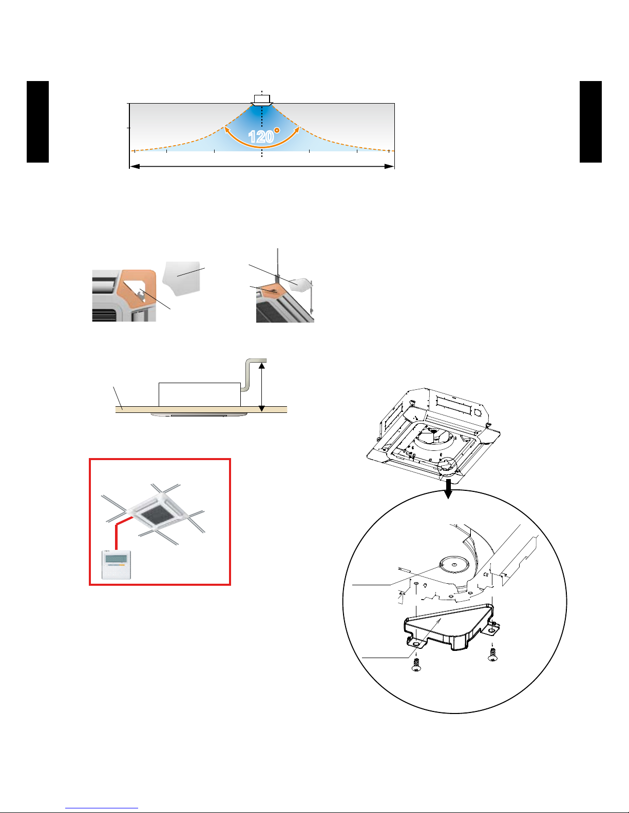
Making space between the ceiling, the air ows far wide and ceiling does not get dirty.
500mm
Wind
velocity
Fast
Slow
3-dimensional wing
: Spin direction : Airflow direction
No airflow
separation
Quiet
< Motor side >
Heat exchanger
Rear part
Front part
Ceiling
Round Flap
Much less temperature irregularity
happens by spreading airow widely
Bottom view
Page 27
- (02-02) -
INDOOR UNIT
(SINGLE)
INDOOR UNIT
(SINGLE)
High lift drain pump
z
850mm
Ceiling panel
Simplication of drain water check
z
Drain and contamination check are possible
without removing the decoration panel.
Can be easily checked by removing the drain
cover.
DRAIN CAP
DRAIN COVER
Easy installation
z
Easy setting by wired
remote controller
Economy operation
z
The power consumption can be reduced.
Wide & powerful airflow
The wind is widely delivered by a high efciency fan and round ap.
Improvement of installation & maintenance
z
Adjustment of nut is possible after installation •
Mounting position of body can be ne adjusted after Decoration panel mounting.
1.5
3
7 5 3 73 5
Side view
Airflow range of 2m / s
120120
[ m ]
[ m ]
Grille corner
Adjustment
can be done just taking
off the corner part
Page 28

- (02-03) -
INDOOR UNIT
(SINGLE)
INDOOR UNIT
(SINGLE)
FUNCTION SETTING
Outlet direction selection
z
Performs operation matched to the number of outlets when 4 directions are unnecessary and •
outlets are blocked when the ceiling cassette is installed in a corner, etc.
4-way direction mode: Set when there are 4 outlets
(shipped state).
3-way direction mode: Set when there are 3 outlets.
4-way direction 3-way direction
Ceiling switching function
z
Also delivers air to high ceilings by selecting the mode and raising the air ow according to the
height of the ceiling.
Low ceiling (Mode 1)
4.2m
3.2m
2.7m
High ceiling (Mode 2) Standard ceiling (Standard)
Standard ...Operates at normal air ow.
Mode 1 ...Air ow becomes smaller than normal.
Mode 2 ...Air ow becomes greater than normal.
Cooling room temperature correction
z
Heating room temperature correction
z
Auto restart
z
The units restart automatically when the current was returned even when there was a power
interruption during operation.
Room temperature sensor switching
z
Switches from room temperature judgment by room temperature sensor attached to indoor
unit body to room temperature judgment by room temperature sensor attached to wired remote
controller.
Page 29
- (02-04) -
INDOOR UNIT
(SINGLE)
INDOOR UNIT
(SINGLE)
DUCT TYPE1-2.
MODEL
ARG36LMLA / AOG36 L AT T
ARG45LMLA / AOG45LATT
FEATURES
Energy efciency class
z
MODEL
ARG36LMLA
Cooling A+
Heating A+
Flexible installation
z
A high installation of degree of freedom according to the construction of the ceiling.
Slim & compact design
z
In the case of bottom suction type, as seen from lower rear part.
In addition to the slim height of 270 mm which is our sales point, further
compactication is attained by reducing 65 mm from the width with the
anking control box embedded inside the chassis.
Embedded in Ceiling Hanging from Ceiling
Control Box united with main unit
One-touch operating and easy-to-install
long-life lter (optional)
Page 30
- (02-05) -
INDOOR UNIT
(SINGLE)
INDOOR UNIT
(SINGLE)
Two-direction drain piping
z
Easy maintenance
z
It can easily access the fan and the motor by the divided panel structure.
Structural improvement is attained by making the
bottom panel two pieces, front and rear.
The internal fan casing is also manufactured in two
pieces, namely upper and lower. The maintenance
of the motor and fan can be easily carried out by
removing the rear panel and the lower part of the
casing while leaving the main chassis installed.
1
3
Bottom panel: 2 units
2
4
1. Control box
2. Fan casing
3. Fan
4. Motor
Quiet operation
z
Quiet operation can be performed in quiet mode.
Economy operation
z
The power consumption can be reduced.
FUNCTION SETTING
Static pressure mode setting
z
Air ow, noise, etc. can be used under the optimum conditions by selecting
the static pressure mode matched to the installation conditions.
Room temperature sensor switching
z
Switches from room temperature judgment by room temperature sensor attached to indoor
unit body to room temperature judgment by room temperature sensor attached to wired remote
controller.
Auto restart
z
The units restart automatically when the current was returned even when
there was a power interruption during operation.
Cooling room temperature correction
z
Heating room temperature correction
z
Duct indoor unit
Two-direction drain piping
Page 31

- (02-06) -
INDOOR UNIT
(SINGLE)
INDOOR UNIT
(SINGLE)
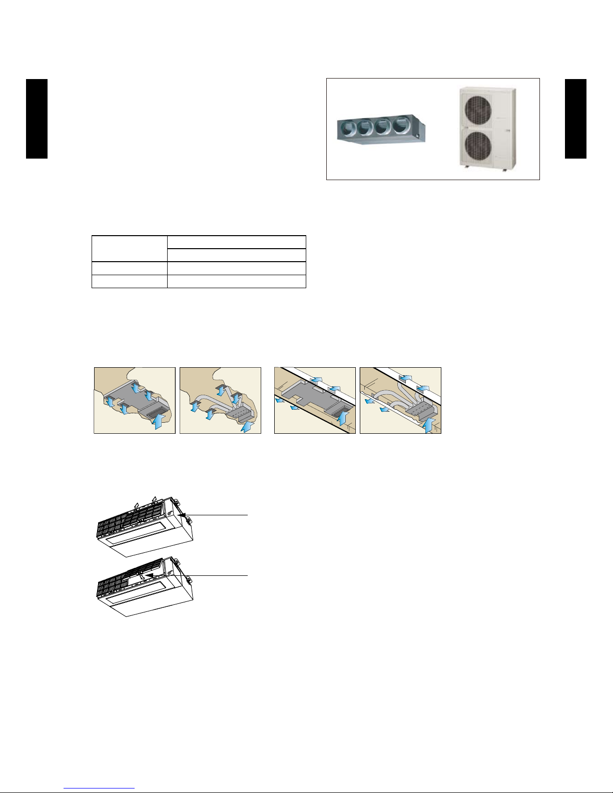
HIGH STATIC PRESSURE DUCT TYPE1-3.
MODEL
ARG45LHTA / AOG45LATT
ARG54LHTA / AOG54LATT
FEATURES
Improvement of market suitability
z
Considerable improvement of installation work by compact size and light weight considering with
the conditions of installation in the ceiling.
The size which the indoor unit can be installed in the spacing between the beams is required for
the installation in the ceiling.
Restriction for dimension of width and height.
Indoor unit installation example
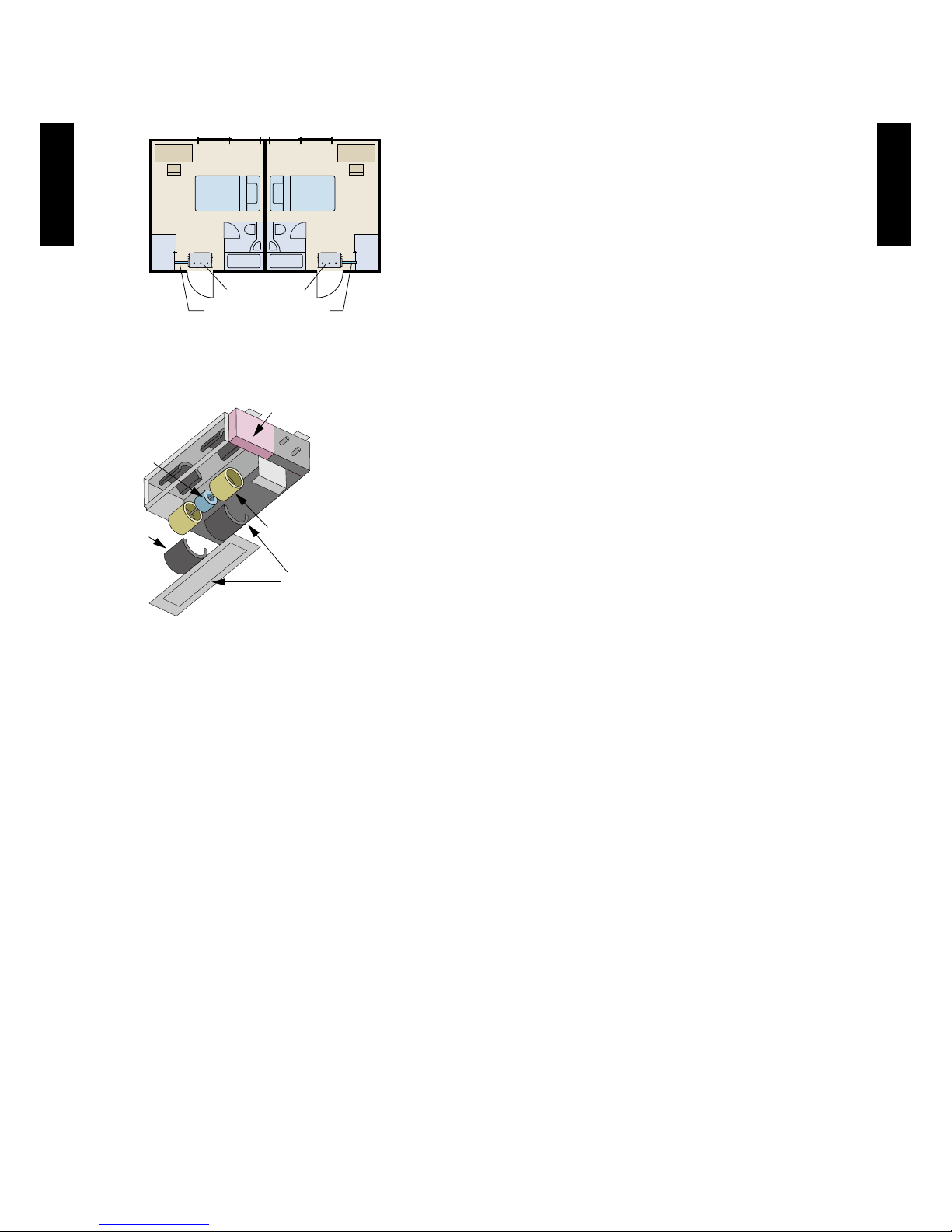
Correspondence to Network
z
Various networks can be constructed according to the user needs.
1.Fresh air output port
Fresh air is connected with the fan of an indoor unit.
2.Electrical heater output port
Electrical heater operates at the time of heating.
3.External input port
Start / Stop of the air conditioner can be changed from the external equipment.
Carrying-in example in the ceiling
Restriction for space when being carried
into the ceiling for replacement
(Ceiling intake grille)
500mm
400mm
750mm
550mm
Indoor Outdoor
Fresh air
Heater
Indoor
Page 32

- (02-07) -
INDOOR UNIT
(SINGLE)
INDOOR UNIT
(SINGLE)
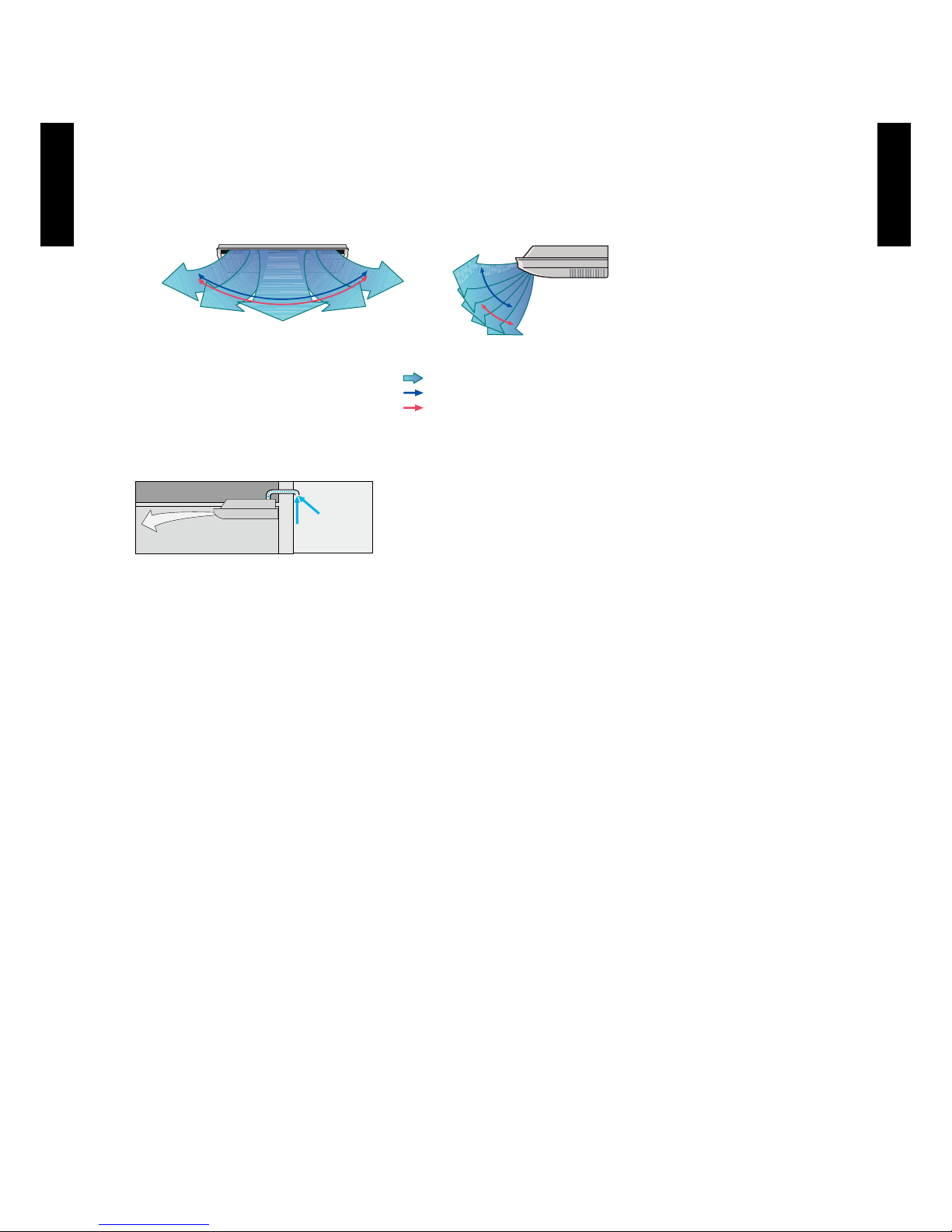
Operation sound (Low noise)
z
Economy operation
z
The power consumption can be reduced.
FUNCTION SETTING
Room temperature sensor switching
z
Switches from room temperature judgment by room temperature sensor attached to indoor
unit body to room temperature judgment by room temperature sensor attached to wired remote
controller.
Auto restart
z
The units restart automatically when the current was returned even when
there was a power interruption during operation.
Cooling room temperature correction
z
Heating room temperature correction
z
Heat exchanger
Plastic fan
Ø225 mm
Heat exchanger
Casing (Plastic)
Turbulent
air flow
Turbulent air ow is reduced by cutting off the corners of
conventional indoor unit front panel and fan case
Low noise is realized by adopting
plastic case, plastic fan
Page 33

- (02-08) -
INDOOR UNIT
(SINGLE)
INDOOR UNIT
(SINGLE)
CEILING TYPE1-4.
MODEL
ABG36LRTA / AOG36 L AT T
ABG45LRTA / AOG45LATT
ABG54LRTA / AOG54LATT
FEATURES
Energy efciency class
z
MODEL
ABG36LRTA
Cooling A++
Heating A+
Quiet operation
z
Air ow mode can be set in 4 steps and more detailed air ow setting is possible.
Economy operation
z
The power consumption can be reduced.
Wired/wireless simultaneous use possible
z
Wired remote controller and wireless remote controller can be simultaneously used.
Flexible installation
z
A high installation of
the construction of the
ceiling and degree of
freedom corresponding
to height is possible.
(Field Supplied)
Open Concealed Wall mounted
Page 34
- (02-09) -
INDOOR UNIT
(SINGLE)
INDOOR UNIT
(SINGLE)
Double auto swing
z
Combination of up/down and right/left air direction swing allows three-dimensional air direction
control.
Since up/down air direction aps operate automatically, according to the operating mode of the
unit, it is possible to set the air direction based on the operating mode.
Fresh-air intake
z
FUNCTION SETTING
Ceiling switching function (standard/high ceiling)
z
Also delivers air to high ceilings by selecting the mode and raising the air ow according to the
height of the ceiling.
Standard ...Operates at normal air ow.
Mode 1 ...Air ow becomes greater than normal.
Auto restart
z
The units restart automatically when the current was returned even when there was a power
interruption during operation.
Room temperature sensor switching
z
Switches from room temperature judgment by room temperature sensor attached to indoor
unit body to room temperature judgment by room temperature sensor attached to wired remote
controller.
Cooling room temperature correction
z
Heating room temperature correction
z
5 steps selectable
1
2
5
4
3
1
2
5
4
3
Steps
Swing: Cooling , Dry and Fan mode
Swing: Heating and Fan mode
5 steps selectable
Right and Left Swing Up and Down Swing
OUTDOOR
Fresh-air
INDOOR
Page 35

- (02-10) -
INDOOR UNIT
(SINGLE)
INDOOR UNIT
(SINGLE)
REMOTE CONTROLLER2.
WIRED REMOTE CONTROLLER2-1.
FEATURES
Various timer setup (ON/OFF/WEEKLY) are possible. ●
Equipped with weekly timer as standard function. ●
(Start/Stop function is twice per day for a week)
When setting up a timer, start/stop and a temperature setup can be ●
changed.
When a failure occurs,the error code is displayed. ●
Error history.(Last 16 error codes can be accessed.) ●
Up to 16 indoor units can be simultaneously controlled. ●
The room temperature can be controlled by being detective the ●
temperature accurately with Built-in thermo sensor.
SET TEMP.
START/STOP
Weekly timer Set back timer
Possible to set ON/OFF time to operate t wice each day of the
week.
Possible to set temperature for two time spans and for each
day of the week.
At "Weekly timer" + "Set back timer" setup
0 3 6 9 12 15 18 21 Time
24°C
SUMOTUWETH FR SA
7
3126 9
15 18 21
SUMOTUWETH FR SA
7
3126 9
15 1 8 21
Easy-to -understand time bar di splay
Exampl e : setup sc reen
(Set to Wedne sday: 8:0 0 to 20:00 .)
Screen
after se tup
0 3 6 9 12 15 18 21 Time
28°C
SUMOTUWETH FR SA
3126 9
15 18 21
Exampl e : setup sc reen
(Set from S unday to Sat urday: 12:0 0 to 15:00, 28 °C .)
24°C
0 3 6 9 12 15 18 21 Time
28°C
24 C 28 C 24 C
Easy-to-understand operation
z
[Variable timer control]
The operation/display sections are zoned according
to time and operation, enabling variable programming
to match application.
Timer
area
Operation
area
Simple installation
z
Components are compatible with standard switch
boxes. Flat back surface allows equipment to be
installed wherever it is needed.
European
switch b ox
JIS box
Simple function setting
z
Setting of the air conditioner selection function is performed by remote controller.
Powerful features and
z
compact size
Accurate and comfortable
z
Indoor temperature can be detected accurately by the inclusion of a
thermo sensor in the body of the wired controller.
Our system can correspond to various scenes.
This wired remote controller and the optional remote sensor allows
exibility in sensor location, and suitable for all requirements.
Built-in timers
z
Sensor part
Thermo sensor
display
Control part for
changing the
thermo sensor
Thermo
sensor
Individual
control
Weekly
timer
Setback
timer
Wired
remote
controller
Page 36

- (02-11) -
INDOOR UNIT
(SINGLE)
INDOOR UNIT
(SINGLE)
1
START/STOP button
Pressed to start and stop operation.
2
SET TEMP. button
Selects the setting temperature.
3
MODE button
Selects the operating mode(AUTO, HEAT, FAN, COOL, DRY).
4
FAN button
Selects the fan speed (AUTO, QUIET, LOW, MED, HIGH).
5
ECONOMY (THERMO SENSOR) button
Turns the economy efcient mode on and off.
6
TIMER MODE (CLOCK ADJUST) button
Selects the timer mode (OFF TIMER, ON TIMER, WEEKLY
TIMER). Set the current time.
7
DAY (DAY OFF) button
Temporarily cancels of one day timer.
8
SET BACK button
Pressed to select the set back timer.
9
Set time button
Pressed to set time.
10
TIMER DELETE button
The schedule of a weekly timer is deleted.
11
TIMER SET button
Sets the date, hour, minute and on-off time.
12
Vertical air ow direction and swing button
Push for two seconds to change the swing mode.
13
Horizontal airow direction and swing button
Push for two seconds to change the swing mode.
14
FILTER RESET button
15
Operation lamp
Lights during operation and when the timer is on.
16
Timer and clock display
17
Operation mode display
18
Fan speed display
19
Operation lock display
20
Temperature display
21
Function display
Defrost display
Thermo sensor display
Economy display
Vertical swing display
Horizontal swing display
Filter display
Note: Functions will be different due to type of indoor unit.
For details, please see operation manual.
FUNCTIONS
Display panel
15
11
10
9
8
2
1
3
5
14
4
12
13
6
7
17
16
18
19
20
21
Page 37

- (02-12) -
INDOOR UNIT
(SINGLE)
INDOOR UNIT
(SINGLE)
SYSTEM DIAGRAM
1-remote controller
z
Primary Secondary
A B C
Indoor unit
Remote controller
2-remote controllers
z
Primary Secondary
Indoor unit
Remote controller
A , B , C : Remote controller cable.
Refer to next page
for detail specications.
A
<
=
500m ; B+C
<
=
500m
ELECTRICAL WIRING
1-remote controller
z
Indoor unit
REMOTE
CONTROLLER
1 2 3
1 2 3
Remote controller
2-remote controllers
z
Primary
Secondary
Indoor unit
1 2 3
1 2 3 1 2 3
REMOTE
CONTROLLER
Remote controllers
1 (RED) : 12V
2 (WHITE) : Signal
3 (BLACK) : COM
DIMENSION
120
120
83.5
15.3
63.5
Hole
45.3
4.54.5
4.5
9
12.5
Hole x 2
Hole x 3
6
30 33.5
23
(120)
18
Front View Side View
Rear View
[Unit : mm]
Page 38
- (02-13) -
INDOOR UNIT
(SINGLE)
INDOOR UNIT
(SINGLE)
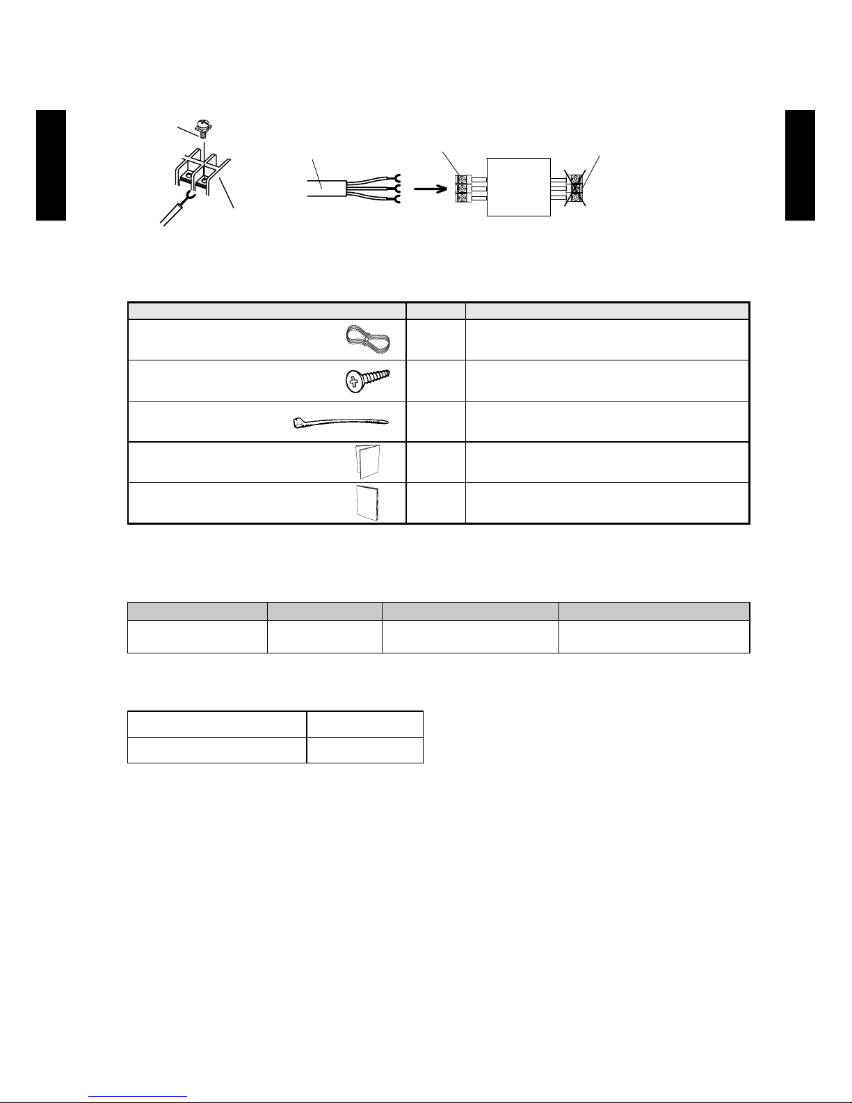
INSTALLATION
Connect the end of remote controller cable directly to the exclusive terminal block.
PCB
M4 screw
Terminal block
Remote
controller
cable
Remote controller
terminal block
Indoor unit
Outdoor unit /
Power supply
terminal block
Note : It may be failed if it is connected to the outdoor unit or the terminal block for power supply.
PACKING LIST (ACCESSORIES)
Name and shape Quantity Application
Remote controller cable (10 m)* 1
For connecting the remote controller
Tapping screw (M4 x 16mm) 2
For installing the remote controller
Cable tie 1
For remote controller and remote
controller cable binding
Installation manual 1
Operation manual 1
* : If necessary , use shielded cable (Field supplied) in accordance with the standard of the country.
WIRING SPECIFICATIONS
Use Size Wire type Remarks
Remote controller
cable
0.33mm
2
(22 AWG)
Polar 3 core Use sheathed PVC cable
SPECIFICATIONS
SIZE (H x W x D mm) 120 x 120 x 18
WEIGHT (g) 160
Page 39

- (02-14) -
INDOOR UNIT
(SINGLE)
INDOOR UNIT
(SINGLE)
WIRELESS REMOTE CONTROLLER2-2.
FEATURES
Four kinds of timer setup (ON/OFF/PROGRAM/SLEEP) are possible.
y
Can be used jointly with wired remote controllers.
y
Easy to change custom code (4 patterns).
y
Built-in timers
z
Select from four different timer programs (ON/OFF/PROGRAM/SLEEP).
Program timer
z
The program timer operates the ON and OFF timer once within a 24 hour period.
Sleep timer
z
The sleep timer function automatically corrects the temperature thermostat setting according to
the time setting to prevent excessive cooling and heating while sleeping.
Cooling operation/dry operation
When the sleep timer is set, the set temperature
automatically rises 1 °C every hour. The set
temperature can rise up to a maximum of 2 °C.
60min.
1 °C
2 °C
Timer setting
Heating operation
When the sleep timer is set, the set temperature
automatically drops 1 °C every 30 minutes. The
set temperature can drop to a maximum of 4 °C.
1 °C
30min.
60min.
90min.
2 °C
3 °C
4 °C
Timer setting
Simple function setting
z
Setting of the air conditioner selection function is performed by remote controller.
Switching remote controller signal code
z
A B C D
A B
C
D
Mixed-up
I.U. I.U. I.U. I.U.
I.U. I.U. I.U. I.U.
After code change
• Code selector switch eliminates unit
being wrongly switched.
(Up to 4 codes can be set.)
*I.U.=Indoor unit
Page 40

- (02-15) -
INDOOR UNIT
(SINGLE)
INDOOR UNIT
(SINGLE)
FUNCTIONS
1
MODE button
Selects the operating mode (AUTO, COOL, DRY, FAN, HEAT).
/Start / end R.C. signal code change. (Max 4 types)
2
10°C HEAT button
* In Group control system, does not function.
3
SET TEMP. button ( ▲ / ▼ )
Sets the indoor temp./ Sets R.C. signal code.
4
ECONOMY button
5
SLEEP button
Pressed to select sleep timer.
6
FAN button
Selects the fan speed (AUTO, HIGH, MED, LOW, QUIET).
7
START/STOP button
Pressed to start and stop operation.
8
SET button (Vertical)
Air ow direction vertical set button.
9
SET button (Horizontal)
Air ow direction horizontal set button.
10
SWING button
Air ow direction swing button.
11
TIMER MODE button
Pressed to select the timer mode. (OFF TIMER, ON TIMER,
PROGRAM TIMER, TIMER RESET)
* In Group control system, does not function.
12
TIMER SET ( / ) button
Sets the current time and on-off time.
* In Group control system, does not function.
13
CLOCK ADJUST button
Sets the current time.
14
RESET button
Used when replacing batteries.
15
TEST RUN button
Used when testing the air conditioner after installation.
16
Signal transmitter
17
Temperature set display
18
Operating mode display
19
Sleep display
20
Transmit indicator
21
Fan speed display
22
Swing display
23
Timer mode display
24
Clock display
Note: Functions will be different due to type of indoor unit.
For details, please see operation manual.
2
4
9
3
1
16
15
5
10
13
11
12
14
8
7
6
Display panel
17
18
20
23
22
21
24
19
Page 41

- (02-16) -
INDOOR UNIT
(SINGLE)
INDOOR UNIT
(SINGLE)
SYSTEM DIAGRAM
Signal transmitter
Signal receiver
window
Control signal might not be recognized in following cases: ●
(i) A curtain or a wall, etc. exists between transmitter and receiver.
(ii) There is an instant-start type (inverter type, etc.) uorescent lamp
in the room.
Air conditioner might not work correctly when strong light hits the ●
signal receiver window. Shut off the direct sunlight and also make
illuminator far away from the receiver window.
DIMENSIONS
Controller
z
56
19
170
Front View Rear View
Top View
Side View
(
Unit : mm
)
Holder
z
Front View Side View Bottom View
60.4
30.2
26.2
Ø 3.5 (HOLE)
3.5 x 6.5 (HOLE)
25.5
154.7
95
Page 42

- (02-17) -
INDOOR UNIT
(SINGLE)
INDOOR UNIT
(SINGLE)
PACKING LIST (ACCESSORIES)
Name and shape Quantity Application
Remote controller holder 1 Use as remote controller holder
Tapping screw (M3 x 12 mm
)
2 For remote controller holder installation
Battery
[ 1.5V (R03 / AA A) ]
2 For remote controller
SPECIFICATIONS
SIZE (H x W x D mm) 170 x 56 x 19
WEIGHT ( g ) 85 (w/o batteries)
Page 43

- (02-18) -
INDOOR UNIT
(SINGLE)
INDOOR UNIT
(SINGLE)
SPECIFICATIONS3.
CASSETTE TYPE3-1.
Type
CASSETTE MODEL
INVERTER HEATPUMP
Model name AUÛG36LRLA AUÛG45LRLA AUÛG54LRLA
Power source 3N ~ 400V 50Hz
Available voltage range 3N ~ 342V - 457V 50Hz
Capacity
Cooling
Rated
kW 10.0 12.5 14.0
Btu/h 34100 42700 47800
Min.-Max.
kW 4.7 - 11.4 5.0 - 14.0 5.4 - 16.0
Btu/h 16000 - 38900 17000 - 47800 18400 - 54600
Heating
Rated
kW 11.2 14.0 16.0
Btu/h 38200 47800 54600
Min.-Max.
kW 5.0 - 14.0 5.4 - 16.2 5.8 - 18.0
Btu/h 17100 - 47800 18400 - 55300 19800 - 61500
Input power
Cooling
Rated
kW
2.44 3.54 4.36
Max. 5.12 5.80 6.48
Heating
Rated 2.56 3.58 4.43
Max. 5.12 5.80 6.48
Current
Cooling
Rated A
3.7 5.3 6.5
Heating 3.9 5.3 6.6
EER Cooling
kW/kW
4.10 3.53 3.21
COP Heating 4.38 3.91 3.61
Moisture removal l/h (pints/h) 3.0 (5.3) 4.5 (7.9) 5.0 (8.8)
Maximum operating current *1
Cooling
A
7.9 8.9 9.9
Heating 7.9 8.9 9.9
Fan
Airow
rate
Cooling
High
m
3
/h
1800 1900 2000
Med 1430 1640 1700
Low 1250 1460 1530
Quiet 1150 1250 1300
Heating
High 1800 1900 2000
Med 1430 1640 1700
Low 1250 1460 1530
Quiet 1150 1250 1300
Type × Q'ty Turbo × 1
Motor output W 80
Sound pressure level
Cooling
High
dB (A)
44 46 47
Med 39 42 43
Low 36 40 41
Quiet 33 36 37
Heating
High 44 46 47
Med 39 42 43
Low 36 40 41
Quiet 33 36 37
Heat exchanger type
Dimensions (H × W × D)
mm
252 × 2021 × 13.3
252 × 2087 × 13.3
252 × 2153 × 13.3
Fin pitch 1.3
Rows x Stages 3 x 12
Pipe type Copper
Fin type Aluminium
Dimensions (H × W × D)
Net
mm
288 × 840 × 840
Gross 360 × 960 × 985
Weight
Net
kg
26
Gross 31
Connection pipe
Size
Liquid
mm
Ø9.52 (3/8 in.)
Gas Ø15.88 (5/8 in.)
Method Flare
Drain hose
Material PVC
Size mm VP25 [Ø25 (I.D.), Ø32 (O.D.)]
Operation range
Cooling
°C 18 to 32
%RH 80 or less
Heating °C 16 to 30
Cassette grille
Model name UTG-UGÛA-W
Material PS
Colour
WHITE
(Approximate colour of MUNSELL N 9.25/)
Dimensions
(H × W × D)
Net
mm
50 × 950 × 950
Gross 115 × 1120 × 1000
Weight
Net
kg
5.5
Gross 8.5
Remote controller type Wired
Note :
Speci cations are base d on the foll owing conditio ns.
Coolin g : Indoor te mperat ure of 27 °CD B / 19 °CWB.an d outdoo r tempera ture of 35 °C DB/24 °C WB.
Heating : I ndoor te mperatu re of 20 °CD B / 15 °CWB.an d outdoor t emperat ure of 7 °CD B/6 °CWB .
Pipe leng th : 5 m, Heig ht diffe rence : 0 m.(O utdoor un it - Indoo r unit)
The prote ctive fu nction m ight work w hen usin g it outsid e the oper ation ra nge.
*1 : The maxi mum curr ent is the ma ximum value when th e operate d with in th e operat ion rang e.
Page 44

- (02-19) -
INDOOR UNIT
(SINGLE)
INDOOR UNIT
(SINGLE)
Model name AUG36LRLA
Energy ef ciency class
Cooling A++
Heating (Average) A+
Pdesign
Cooling
kW
10.0 (35°C)
Heating (Average) 10.0 (-10°C)
SEER Cooling
kWh/kWh
6.50
SCOP Heating (Average) 4.30
Annual energy consumption
QCE
kWh/a
538
QHE (Average) 3253
Sound power level
Cooling
High dB (A)
58
Heating 58
Page 45

- (02-20) -
INDOOR UNIT
(SINGLE)
INDOOR UNIT
(SINGLE)
DUCT TYPE3-2.
Typ e
DUCTED M ODEL
INVERT ER HEATPU MP
Model na me ARÛG36LMLA ARÛG45LMLA
Power sour ce 3N~ 40 0V 50Hz
Available v oltage r ange 3N~ 3 42V - 457V 5 0Hz
Capacity
Cooling
Rated
kW 10.0 12.5
Btu/h 3410 0 42700
Min.-Max.
kW 4.7 - 11.4 5.0 - 14. 0
Btu/h 16000 - 3 8900 17100 - 4780 0
Heating
Rated
kW 11. 2 14.0
Btu/h 38200 47800
Min.-Max.
kW 5.0 - 14.0 5.4 - 16. 2
Btu/h 17100 - 4780 0 18400 - 55 300
Input powe r
Cooling
Rated
kW
2.84 3.89
Max. 5.1 2 5.80
Heating
Rated 2.87 3.88
Max. 5.1 2 5.80
Current
Cooling
Rated A
4.3 5.8
Heating 4.4 5.8
EER Cooling
kW/kW
3.52 3.21
COP Heating 3.90 3.61
Moistur e removal l/h (pin ts/h) 3.0 (5.3) 4.5 (7.9)
Maximum operating current *1
Cooling
A
8.5 9.5
Heating 8.5 9.5
Fan
Airow
rate
Cooling
High
m
3
/h
1800 2100
Med 1550 1750
Low 123 0 1350
Quiet 970 1070
Heating
High 1850 2100
Med 1550 1750
Low 123 0 1350
Quiet 970 1070
Type × Q'ty Siroc co × 2
Motor out put W 197
Recomm ended st atic pres sure Pa 30 to 150 30 to 150
Sound pre ssure leve l
Cooling
High
dB(A)
38 42
Med 36 38
Low 31 32
Quiet 26 28
Heating
High 40 42
Med 36 38
Low 31 32
Quiet 26 28
Heat excha nger typ e
Dimensi ons (H × W × D)
mm
294 × 100 0 × 53.2
Fin pitch 1.4 0
Rows x Stag es 4 × 14
Pipe typ e Copper
Fin type Alumini um
Enclosu re
Material Steel
Colour -
Dimensions
( H×W ×D )
Net
mm
270 × 1135 × 700
Gross 30 0 × 1320 × 790
Weight
Net
kg
40
Gross 47
Connec tion pip e
Size
Liquid
mm
Ø9.52 (Ø3 / 8 in .)
Gas Ø15.88 (Ø5 / 8 in.)
Method Flare
Drain po rt
Material Steel
Size mm Ø36.0 (I. D.), Ø38.0 (O.D.)
Operat ion rang e
Cooling
°C 18 to 32
%RH 80 or les s
Heating °C 16 to 30
Remote co ntrolle r type Wired
Note :
Speci cations are base d on the foll owing conditio ns.
Coolin g : Indoor te mperat ure of 27 °CD B / 19 °CWB.an d outdoo r tempera ture of 35 °C DB/24 °C WB.
Heating : I ndoor te mperatu re of 20 °CD B / 15 °CWB.an d outdoor t emperat ure of 7 °CD B/6 °CWB .
Standa rd static p ressur e : ARÛG36LM : 47Pa ARÛG45LM : 60Pa
Static p ressure m ode : ARÛG36LM : Normal , ARÛG45LM : High stat ic pressure mode 1
Pipe leng th : 5 m, Heig ht diffe rence : 0 m.(O utdoor un it - Indoo r unit)
Sound pre ssure leve l : Instal l a 2m duct to th e outlet po rt and a 1m duc t to the suction poi t and measu re.
The prote ctive fu nction m ight work w hen usin g it outsid e the oper ation ra nge.
Drain ho se should b e eld sup plied.
*1 : The maxi mum curr ent is the ma ximum value when th e operate d with in th e operat ion rang e.
Page 46

- (02-21) -
INDOOR UNIT
(SINGLE)
INDOOR UNIT
(SINGLE)
Model name ARG36LMLA
Energy ef ciency class
Cooling A+
Heating (Average) A+
Pdesign
Cooling
kW
10.0 (35°C)
Heating (Average) 10.0 (-10°C)
SEER Cooling
kWh/kWh
5.80
SCOP Heating (Average) 4.00
Annual energy consumption
QCE
kWh/a
603
QHE (Average) 3497
Sound power level
Cooling
High dB (A)
65
Heating 67
Page 47

- (02-22) -
INDOOR UNIT
(SINGLE)
INDOOR UNIT
(SINGLE)
HIGH STATIC PRESSURE DUCT TYPE3-3.
Type
DUCTED MODEL
INVERTER HEATPUMP
Model name ARÛG45LHTA ARÛG54LHTA
Power source 3N~ 400V 50Hz
Available voltage range 3N~ 342V - 457V 50Hz
Capacity
Cooling
Rated
kW 12.5 14.0
Btu/h
42700 47800
Min.-Max.
kW 5.0 - 14.0 5.4 - 16.0
Btu/h
17100 - 47800 18400 - 54600
Heating
Rated
kW 14.0 16.0
Btu/h
47800 54600
Min.-Max.
kW 5.4 - 16.2 5.8 - 18.0
Btu/h
18400 - 55300 19800 - 61500
Input power
Cooling
Rated
kW
4.06 4.65
Max. 6.14 6.83
Heating
Rated 3.67 4.37
Max. 6.14 6.83
Current
Cooling
Rated A
6.1 6.9
Heating 5.5 6.5
EER Cooling
kW/kW
3.08 3.01
COP Heating 3.81 3.66
Moisture removal l/h (pints/h) 1.5 (2.6) 2.5 (4.4)
Maximum operating current *1
Cooling
A
11.0 12.0
Heating
11.0 12.0
Fan
Airow
rate
Cooling
High
m
3
/h
3350 3350
Med 2850 2850
Low 2430 2430
Quiet - -
Heating
High 3350 3350
Med 2850 2850
Low 2430 2430
Quiet - Type × Q'ty Sirocco × 2
Motor output W 490
Recommended static pressure Pa 100 to 250 100 to 250
Sound pressure level
Cooling
High
dB(A)
47 47
Med 43 43
Low 40 40
Quiet - -
Heating
High 47 47
Med 43 43
Low 40 40
Quiet - -
Heat exchanger type
Dimensions (H × W × D)
mm
336 × 890 × 53.2
Fin pitch 1.30
Rows x Stages 4 × 16
Pipe type Copper
Fin type Aluminium
Enclosure
Material Steel
Colour -
Dimensions
(H × W × D)
Net
mm
400 × 1050 × 500
Gross 460 × 1230 × 640
Weight
Net
kg
46
Gross 51
Connection pipe
Size
Liquid
mm
Ø9.52 (Ø3 / 8 in.)
Gas Ø15.88 (Ø5 / 8 in.)
Method Flare
Drain
port
Material Steel
Size mm Ø23.4 (I.D.), Ø25.4 (O.D.)
Operation range
Cooling
°C 18 to 32
%RH 80 or less
Heating °C 16 to 30
Remote controller type Wired
Note :
Speci cations are base d on the foll owing conditio ns.
Coolin g : Indoor te mperat ure of 27 °CD B / 19 °CWB.an d outdoo r tempera ture of 35 °C DB/24 °C WB.
Heating : I ndoor te mperatu re of 20 °CD B / 15 °CWB.an d outdoor t emperat ure of 7 °CD B/6 °CWB .
Standa rd static p ressur e : 100 Pa.
Pipe leng th : 5 m, Heig ht diffe rence : 0 m.(O utdoor un it - Indoo r unit)
Sound pre ssure leve l : Instal l a 2m duct to th e outlet po rt and a 1m duc t to the suction poi t and measu re.
The prote ctive fu nction m ight work w hen usin g it outsid e the oper ation ra nge.
Drain ho se should b e eld sup plied.
*1 : The maxi mum curr ent is the ma ximum value when th e operate d with in th e operat ion rang e.
Page 48
- (02-23) -
INDOOR UNIT
(SINGLE)
INDOOR UNIT
(SINGLE)
CEILING TYPE3-4.
Typ e
CEILIN G MODEL
INVER TER HEATPU MP
Model na me ABG3 6LR TA ABG4 5LR TA ABG5 4LR TA
Power source 3N~ 40 0V 50H z
Availabl e voltag e range 3N~ 3 42V - 457 V 50Hz
Capacity
Cooling
Rated
kW 10 .0 12. 5 14.0
Btu/h
341 00 42700 47800
Min.-Max.
kW 4. 7-11.4 5.0-14.0 5.4 -16.0
Btu/h
16000-38900 17000-47800 18400-54600
Heating
Rated
kW 11.2 14.0 16.0
Btu/h
38200 4780 0 54600
Min.-Max.
kW 5.0 -14.0 5.4 -16.2 5.8 -18.0
Btu/h
17100-47800 18400-55300 19800-61500
Input pow er
Cooling
Rated
kW
2.84 3.8 9 4.6 5
Max. 5 .12 5.8 0 6.48
Heating
Rated 2 .87 3.88 4.67
Max. 5 .12 5.8 0 6.48
Current
Cooling
Rated A
4.3 5.8 6.9
Heating 4.4 5.8 6.9
EER Cooling
kW/kW
3.52 3 .21 3 .01
COP Heating 3.90 3.61 3.43
Moistu re remova l l/h (pi nts/h) 3.0 (5.3) 4.5 (7.9) 5.0 (8.8)
Maximum operating current *1
Cooling
A
7.9 8.9 9.9
Heating
7.9 8.9 9.9
Fan
Air ow
rate
Cooling
High
m3/h
1900 2100 230 0
Med 1500 1700 1950
Low 120 0 1400 1600
Quiet 1000 110 0 13 00
Heating
High 1900 210 0 2300
Med 1500 1700 1950
Low 120 0 1400 1600
Quiet 1000 110 0 13 00
Type × Q'ty Siroc co× 4
Motor ou tput W 130
Sound pr essure l evel
Cooling
High
dB (A)
47 49 51
Med 43 45 48
Low 37 39 42
Quiet 32 34 38
Heating
High 47 49 51
Med 43 45 48
Low 37 39 42
Quiet 32 34 38
Heat excha nger ty pe
Dimens ions (H × W × D)
mm
252 x 1350 x 39. 9
252 x 1350 x 39. 9
168 x 1350 x 13.3
Fin pitch 1.45 1. 45
Rows x Sta ges 3 x 12 3 x 12 + 1 x 8
Pipe ty pe Copper
Fin type Aluminium
Enclosure
Material ABS
Colour
WHITE
(Approx imate colour of M UNSEL L N9.25 /)
Dimensions
(H × W × D)
Net
mm
240 × 1660 × 70 0
Gross 318 × 1800 × 795
Weight
Net
kg
46 48
Gross 58 60
Connec tion pi pe
Size
Liquid
mm
Ø9.52 (3/ 8 in.)
Gas Ø15.88 (5/ 8 in.)
Method Flare
Drain
port
Material ABS
Size mm Ø21.5 (I. D.), Ø26.0 (O.D.)
Operat ion ran ge
Cooling
°C 18 to 32
%RH 80 or les s
Heating °C 16 to 30
Remote co ntroll er typ e Wireless
Note :
Speci cations are base d on the foll owing conditio ns.
Coolin g : Indoor te mperat ure of 27 °CD B / 19 °CWB.an d outdoo r tempera ture of 35 °C DB/24 °C WB.
Heating : I ndoor te mperatu re of 20 °CD B / 15 °CWB.an d outdoor t emperat ure of 7 °CD B/6 °CWB .
Pipe leng th : 5 m, Heig ht diffe rence : 0 m.(O utdoor un it - Indoo r unit)
The prote ctive fu nction m ight work w hen usin g it outsid e the oper ation ra nge.
Drain ho se should b e eld sup plied.
*1 : The maxi mum curr ent is the ma ximum value when th e operate d with in th e operat ion rang e.
Page 49

- (02-24) -
INDOOR UNIT
(SINGLE)
INDOOR UNIT
(SINGLE)
Model name ABG3 6LR TA
Energy ef ciency class
Cooling A++
Heating (Average) A+
Pdesign
Cooling
kW
10.0 (35°C)
Heating (Average) 10.0 (-10°C)
SEER Cooling
kWh/kWh
6.1 0
SCOP Heating (Average) 4.1 0
Annual energy consumption
QCE
kWh/a
573
QHE (Average) 3414
Sound power level
Cooling
High dB (A)
61
Heating 61
Page 50

- (02-25) -
INDOOR UNIT
(SINGLE)
INDOOR UNIT
(SINGLE)
DIMENSIONS4.
CASSETTE TYPE4-1.
MODEL : AUG36LR, AUG45LR, AUG54LR
Ceiling opening and hanging bolt pitch
z
(Unit : mm)
Refrigerant piping and drain piping positions
z
Airow split-ow duct and fresh air inlet positions
z
288
298
40
10
140 - 145
50 - 100
950 (Panel frame)
50
80
130
130
200
840 (Body frame)
795 (Hanging bolt pitch)
699 (Hanging bolt pitch)
860 - 910 (Ceiling opening)
950 (Panel frame)
840 (Body frame)
860 - 910 (Ceiling opening)
20 - 45 20 - 45
20 - 4520 - 45
130
60278358
140
180
200
Drain pipe
(Connect the attached drain hose)
250
352
100
8383
90
185
100
Fresh air inlet position
Detailed diagram of branched duct connecting port
(4 sides)
Knockout hole pitch
Cut out
Cut out
10 x Ø2.5 hole
4 x Ø2.5 hole
Ø88 Ø70
185
Airflow split-flow duct connecting port
Airflow split-flow duct connecting port
Fresh air inlet position
Drain pipe
Refrigerant pipe
Airflow split-flow duct connecting port
Airflow split-flow duct connecting port
Page 51

- (02-26) -
INDOOR UNIT
(SINGLE)
INDOOR UNIT
(SINGLE)
INSTALLATION PLACE
(Unit : mm)
3,000 or more
1,000 or more
1,500
or more
298 or more
1,800
or more
H
Strong and durable ceiling
Obstruction
Floor
H (The maximum height from oor to ceiling) (mm)
Model name AUG36LR AUG45LR AUG54LR
Low mode 2,700 2,700 2,700
Standard mode 3,200 3,200 3,200
High Ceiling mode 4,200 4,200 4,200
3-way directions setting
z
(Unit : mm)
To set “3-way directions”, the air outlet shutter plate (UTR-YDZC) sold separately must be installed
and “outlet-direction” switched to “3-way” by remote controller.
*When installing the indoor unit, be careful about the maintenance hole.
100 or more*
Page 52

- (02-27) -
INDOOR UNIT
(SINGLE)
INDOOR UNIT
(SINGLE)
DUCT TYPE4-2.
MODEL : ARG36LM, ARG45LM
(Unit : mm)
Refrigerant piping flare connection (Gas)
Refrigerant piping flare connection (Liquid)
Drain piping connection
Drain piping connection with cap.
Knock out hole for fresh air.
Front view
Top view
Side view (L)
Side view (R)
Rear view
Page 53

- (02-28) -
INDOOR UNIT
(SINGLE)
INDOOR UNIT
(SINGLE)
INSTALLATION PLACE
(Unit : mm)
MAINTENANCE SPACE
WHEN USING A SQUARE DUCT
BOTTOM AIR INTAKE HOLE
150 or more300 or more
Floor
2500 or more
(When no ceiling)
It shall be possible to install and remove
the control box.
Service access
Control box
300 or more
500 or more
500 or more
100
It shall be possible to install and remove
the control box, fan units and lter.
Service access
Intake panel
Control box
300 or more
500 or more
1550 or more
100
Ø 3.2
219
46
18
P176 x 6 = 1044
109
23
108 1015
16 240
Page 54

- (02-29) -
INDOOR UNIT
(SINGLE)
INDOOR UNIT
(SINGLE)
HIGH STATIC PRESSURE DUCT TYPE4-3.
MODEL : ARG45LH, ARG54LH
(Unit : mm)
Refrigerant piping flare connection (Liquid)
Refrigerant piping flare connection (Gas)
Front view
Top view
Side view (L)
Side view (R)
Rear view
Page 55

- (02-30) -
INDOOR UNIT
(SINGLE)
INDOOR UNIT
(SINGLE)
INSTALLATION PLACE
(Unit : mm)
Installation by which service space is made on top of the unit (recommended).
350 or
more
450 or more
(Service space)
Service access
Installation by which service is carried out from the bottom of the unit.
20 or
more
450 or more
(Service space)
Service access
MAINTENANCE SPACE
: Service access : Service space
Unit
AIR
AIR
Provide a service access for inspection purposes as shown below.
Do not place any wiring or illumination in the service space, as
they will impede service.
Control box
450 or more
300300
(
500
)
30
(
500
)
Page 56

- (02-31) -
INDOOR UNIT
(SINGLE)
INDOOR UNIT
(SINGLE)
CEILING TYPE4-4.
MODEL : ABG36LR, ABG45LR, ABG54LR
(Unit : mm)
Top view
Side view
Rear view
1 2 3
45
6
30 30
Suspension bolt pitch
1,600
INDOOR UNIT (Top view)
Dimensions
(Space Required
for Installation)
10
155
300
INDOOR UNIT
Suspension bolt
should extend
outward 30 to 75.
Refrigerant piping flare connection (Gas)
Refrigerant piping flare connection (Liquid)
Drain piping connection
Knock out hole for fresh air
Knock out hole for refrigerant piping
Hole for lifting bolt (Use M10 screw bolt)
Page 57

- (02-32) -
INDOOR UNIT
(SINGLE)
INDOOR UNIT
(SINGLE)
INSTALLATION PLACE
(Unit : mm)
80 or more 150 or more
10 or more
2500 or more
1000 or more
INDOOR UNIT
Ceiling
Ceiling
Obstruction
Floor
INDOOR UNIT
Ceiling panel
Ceiling panel
80 or more 150 or more
10 or more
2500 or more
1000 or more
Obstruction
Floor
Page 58

- (02-33) -
INDOOR UNIT
(SINGLE)
INDOOR UNIT
(SINGLE)
WIRING DIAGRAMS5.
CASSETTE TYPE5-1.
MODEL : AUG36LR, AUG45LR, AUG54LR
Page 59

- (02-34) -
INDOOR UNIT
(SINGLE)
INDOOR UNIT
(SINGLE)
DUCT TYPE5-2.
MODEL : ARG36LM, ARG45LM
Page 60

- (02-35) -
INDOOR UNIT
(SINGLE)
INDOOR UNIT
(SINGLE)
HIGH STATIC PRESSURE DUCT TYPE5-3.
MODEL : ARG45LH, ARG54LH
Page 61

- (02-36) -
INDOOR UNIT
(SINGLE)
INDOOR UNIT
(SINGLE)
CEILING TYPE5-4.
MODEL : ABG36LR, ABG45LR, ABG54LR
Page 62

- (02-37) -
INDOOR UNIT
(SINGLE)
INDOOR UNIT
(SINGLE)
CAPACITY TABLE6.
COOLING CAPACITY6-1.
CASSETTE TYPE6-1-1.
This table is created using the maximum capacity.
MODEL : AUG36LR
MODEL : AUG45LR
MODEL : AUG54LR
AFR: Air F low Rate (m³/m in.)
TC: Total Capaci ty (kW)
SHC: Sens ible Hea t Capacit y (kW)
IP: Input Po wer (kW)
AFR 30.0
Indoor t empera ture
°CDB 18 21 23 25 27 29 32
°CWB 12 15 16 18 19 21 23
Outdoo r temper ature
°CDB TC SHC IP TC SHC IP TC SHC IP TC SHC IP TC SHC IP TC SHC IP TC SHC IP
-15 8.83 6.90 1.40 9.84 6.95 1.42 10.17 7.55 1.43 10.85 7.58 1.44 11.18 8.18 1.45 11.85 8.15 1.47 12.52 8 .68 1.48
-10 8.76 6.65 1.41 9.76 6.69 1.44 10.10 7.27 1.44 10.76 7.29 1.46 11.09 7.87 1.47 11.76 7.84 1.48 12.43 8. 35 1.50
0 8.6 8 6.61 1.49 9.67 6.65 1.51 10.00 7.23 1.52 10.66 7.25 1.54 10. 99 7.83 1.55 11.65 7.80 1.56 12. 31 8. 31 1.58
5 8.6 3 6.66 1.59 9.61 6.70 1.62 9.94 7.28 1.63 10 .59 7.30 1.64 10.92 7.89 1.65 11.58 7.86 1.67 12.23 8 .37 1.69
10 8.59 6.74 1.72 9.57 6.78 1.74 9.90 7.38 1.75 10.55 7.40 1.77 10.8 8 7.99 1.78 11.53 7.96 1.80 12.18 8.48 1.81
15 8.55 6.72 1.92 9.52 6.76 1.95 9.84 7.35 1.96 10.49 7.38 1.98 10.82 7.97 1.99 11.47 7.93 2.01 12.12 8.45 2.03
20 8 .77 6.43 2.36 9.77 6.47 2.40 10 .10 7.03 2.41 10.77 7.05 2.43 11.10 7. 62 2.45 11.77 7.59 2.47 12.44 8 .08 2.49
25 8 .89 6.56 2.79 9.91 6.60 2.84 10.24 7.17 2.8 5 10.92 7.20 2.88 11.26 7.77 2.90 11.93 7.7 4 2. 92 12. 61 8. 25 2.95
30 9.17 6.69 3.32 10.22 6.73 3.37 10. 57 7.32 3.38 11.26 7.34 3.42 11.61 7.93 3.44 12.31 7.90 3. 47 13.0 0 8. 41 3.50
35 8. 85 6.59 3.68 9.86 6.62 3.74 10.19 7.20 3.76 10. 86 7.23 3.8 0 11.40 7.80 3.82 11.87 7.77 3.86 12.54 8. 28 3.89
40 8 .01 6.20 3.80 8.93 6.24 3.86 9.23 6.78 3.88 9 .84 6.80 3.92 10.14 7.35 3.94 10.75 7.32 3.98 11.36 7.79 4.02
46 6 .79 5.65 3.84 7.57 5.69 3.90 7.83 6 .18 3.92 8.34 6.20 3 .96 8.60 6.70 3.98 9.1 2 6.6 7 4.02 9.63 7.11 4.0 6
AFR 31.7
Indoor t empera ture
°CDB 18 21 23 25 27 29 32
°CWB 12 15 16 18 19 21 23
Outdoo r temper ature
°CDB TC SHC IP TC SHC IP TC SHC IP TC SHC IP TC SHC IP TC SHC IP TC SHC IP
-15 10.62 7.73 1.57 11.83 7.77 1.59 12.23 8 .45 1.60 13.0 4 8. 48 1.62 13.4 4 9.15 1.62 14. 25 9.12 1.64 15.06 9.71 1.66
-10 10. 51 7.70 1.62 11.71 7.75 1.64 12 .11 8.42 1.65 12.91 8.4 5 1.67 13.31 9 .12 1.6 7 14.11 9.09 1.69 14.91 9.6 8 1.71
0 10.42 7.58 1.71 11.60 7.62 1.73 12. 00 8. 29 1.74 12.79 8.32 1.76 13.19 8.9 8 1.77 13.98 8.94 1.79 14.77 9.53 1.81
5 10.28 7.56 1.81 11.45 7.61 1.84 11.84 8.2 7 1.85 12.62 8.30 1.87 13. 01 8.9 6 1.88 13.79 8.92 1.89 14.57 9. 51 1.91
10 10.17 7.59 1.92 11.33 7.64 1.95 11.72 8.3 0 1.96 12.49 8.33 1.98 12. 88 8. 99 1.99 13.6 5 8.9 6 2.01 14.42 9.54 2.03
15 10.10 7.66 2.08 11.26 7.71 2.11 11.64 8.38 2.13 12.41 8.41 2 .15 12.7 9 9.0 8 2.16 13.5 6 9.04 2.18 14.33 9.63 2.20
20 10 .38 7.46 2.40 11.56 7. 51 2.43 11.96 8.16 2.45 12.75 8.19 2.47 13.14 8.84 2.48 13.93 8. 81 2.51 14.72 9.38 2.53
25 10.76 7.77 2.86 11.99 7.81 2.90 12.4 0 8.5 0 2.92 13.21 8.52 2.95 13. 62 9. 20 2.96 14.4 4 9.17 2 .99 15.26 9.77 3.02
30 11.30 7.83 4.2 9 12.59 7.87 4.36 13. 02 8. 56 4.38 13.8 8 8.5 9 4.43 14.31 9.27 4.45 15.17 9.24 4.49 16.02 9. 84 4.54
35 11.06 7.77 4.72 12.32 7.82 4.80 12.74 8.50 4.82 13. 58 8. 53 4.87 14.0 0 9.21 4.9 0 14.84 9.17 4.94 15.68 9.7 7 4.99
40 10.16 7.33 4.87 11.32 7.38 4.94 11.70 8.02 4.97 12. 48 8. 05 5.02 12.8 6 8.6 9 5.04 13.63 8.65 5.09 14. 40 9. 22 5.14
46 8. 26 6.44 4.17 9.20 6.48 4.24 9.51 7.05 4.26 10.14 7.07 4.30 10.45 7.63 4.32 11.08 7.60 4.37 11.71 8.10 4.41
AFR 33.3
Indoor t empera ture
°CDB 18 21 23 25 27 29 32
°CWB 12 15 16 18 19 21 23
Outdoo r temper ature
°CDB TC SHC IP TC SHC IP TC SHC IP TC SHC IP TC SHC IP TC SHC IP TC SHC IP
-15 11.86 9.04 2 .12 13.2 2 9.09 2.16 13.67 9. 89 2.17 14.5 7 9.9 2 2.19 15.02 10.71 2.20 15.92 10.67 2.22 16.82 11.37 2.2 4
-10 11.74 8.51 2.23 13. 08 8. 56 2.27 13.5 3 9.3 0 2.28 14.42 9.33 2.30 14. 86 10.08 2 .31 15.76 10.0 4 2.3 4 16.65 10.70 2.36
0 11.68 8 .38 2.30 13.01 8.43 2.34 13.45 9.1 6 2.35 14.34 9.1 9 2.37 14.78 9. 92 2.39 15.6 7 9.8 8 2.41 16.55 10.53 2.43
5 11.58 8 .40 2.35 12.90 8. 45 2.39 13.3 4 9.19 2.40 14.21 9.21 2.42 14.65 9.95 2.44 15. 53 9. 91 2.46 16. 41 10.5 6 2.49
10 11.47 8 .44 2.42 12.78 8.4 9 2.46 13.21 9.22 2.48 14.0 8 9. 25 2.50 14.52 9.99 2.51 15. 39 9. 95 2.54 16. 26 10.6 0 2.5 6
15 11.49 8.43 2.53 12.8 0 8.4 8 2.57 13.24 9.22 2.58 14.11 9.25 2.61 14.55 9. 99 2.62 15. 42 9.9 5 2.65 16.2 9 10.60 2.67
20 11.90 8. 47 2.96 13.2 6 8.52 3.01 13.71 9. 26 3.02 14. 61 9. 29 3.05 15.0 6 10.04 3.07 15.97 10.0 0 3 .10 16.87 10.65 3 .13
25 12.39 8. 84 3.53 13.81 8.8 9 3.58 14.28 9.66 3.60 15. 22 9 .70 3.64 15.6 9 10.47 3.65 16 .63 10. 43 3. 69 17.57 11.11 3.73
30 12.77 8.8 9 4.93 14.23 8.94 5.01 14.71 9.72 5.03 15.68 9.75 5.09 16.17 10.53 5.11 17.14 10.49 5.16 18.11 11.18 5.21
35 12. 64 8 .93 5.40 14.0 8 8.9 8 5.48 14.56 9.77 5.51 15 .52 9. 80 5.57 16.0 0 10.5 8 5.5 9 16.9 6 10.54 5.65 17.92 11.23 5.71
40 11.62 8.4 3 5.54 12.94 8.48 5.63 13. 38 9. 22 5.66 14.2 6 9.25 5.71 14.70 9.99 5.74 15. 59 9. 95 5.80 16. 47 10.6 0 5.8 6
46 8. 88 7.1 7 4.21 9.89 7.21 4.28 10. 23 7.84 4.3 0 10.91 7.87 4.34 11.24 8.4 9 4.36 11.92 8.46 4.41 12. 59 9. 01 4.45
Page 63

- (02-38) -
INDOOR UNIT
(SINGLE)
INDOOR UNIT
(SINGLE)
DUCT TYPE6-1-2.
This table is created using the maximum capacity.
MODEL : ARG36LM
MODEL : ARG45LM
AFR: Air F low Rate (m³/mi n.)
TC: Total Capaci ty (kW)
SHC: Sens ible Heat Capacit y (kW)
IP: Input Po wer (kW)
AFR 30.8
Indoor t empera ture
°CDB 18 21 23 25 27 29 32
°CWB 12 15 16 18 19 21 23
Outdoo r temper ature
°CDB TC SHC IP TC SHC IP TC SHC IP TC SHC IP TC SHC IP TC SHC IP TC SHC IP
-15 8.6 0 6.85 1.4 4 9.58 6. 89 1.46 9. 91 7.49 1.47 10. 56 7. 51 1.48 10.89 8 .11 1.49 11.54 8. 08 1.51 12.19 8.61 1.52
-10 8. 52 6.57 1.48 9.49 6. 61 1.50 9.8 2 7.19 1.51 10.46 7.21 1.52 10.79 7.79 1.53 11.43 7.7 6 1.5 5 12.08 8.26 1. 56
0 8 .47 6.56 1.5 7 9.43 6. 60 1.60 9 .76 7.18 1.61 10.4 0 7.20 1.62 10.72 7.78 1.63 11.3 6 7.7 4 1.65 12.01 8 .25 1.66
5 8. 42 6.62 1.6 6 9.38 6. 66 1.69 9 .70 7.24 1.70 10.34 7.26 1.72 10.66 7.84 1.72 11.30 7.81 1 .74 11.94 8 .32 1.76
10 8.39 6.72 1.77 9. 35 6.76 1.8 0 9.67 7.35 1.81 10.31 7.37 1.83 10.62 7.96 1.84 11.26 7.93 1.85 11.90 8.45 1.87
15 8.3 3 6.69 2 .10 9.27 6.73 2.13 9. 59 7.31 2.14 10.22 7.34 2.16 10.54 7.92 2 .17 11.17 7.89 2. 20 11.80 8. 41 2.22
20 8.51 6.3 4 2.50 9.4 8 6.38 2.5 4 9.80 6.9 4 2.56 10.44 6.9 6 2. 58 10.77 7.5 1 2.59 11.41 7.48 2. 62 12.06 7.97 2 .65
25 8.64 6.5 0 2.94 9.6 3 6.54 2.9 9 9.96 7.11 3.01 10.61 7.1 3 3. 04 10 .94 7.70 3.05 11.60 7.67 3.08 12.26 8.1 7 3 .11
30 8.97 6.66 3.43 10.00 6.70 3.4 8 10.34 7.29 3.5 0 11.02 7.31 3.54 11.36 7.89 3.5 5 12.04 7.86 3. 59 12.72 8.37 3 .62
35 8 .85 6 .71 3.80 9.8 6 6.75 3.8 6 10.19 7.34 3.88 10.8 6 7.36 3.92 11 .40 7.95 3. 94 11.87 7.92 3.97 12.54 8. 43 4.01
40 8.00 6.2 5 4.00 8.91 6 .28 4.06 9.21 6.8 3 4.08 9.82 6 .85 4.12 10.12 7.40 4.1 5 10.73 7.37 4.1 9 11.34 7.85 4.2 3
46 6.78 5.6 5 4.06 7.55 5 .68 4 .12 7.81 6.18 4.14 8.3 2 6.20 4.18 8.58 6.69 4.21 9 .09 6.66 4.25 9.61 7.10 4.29
AFR 35 .0
Indoor t empera ture
°CDB 18 21 23 25 27 29 32
°CWB 12 15 16 18 19 21 23
Outdoo r temper ature
°CDB TC SHC IP TC SH C IP TC SHC IP TC SHC IP TC SHC IP TC SHC IP TC SH C IP
-15 10.3 8 7.83 1.63 11.57 7. 88 1.6 6 11.96 8.56 1.6 6 12.75 8.59 1.68 13.14 9. 28 1.69 13.9 3 9.24 1.71 14.72 9.8 4 1.72
-10 10.3 3 7.84 1.68 11.50 7. 89 1.71 11.89 8.5 8 1.72 12.68 8.61 1.73 13.07 9.29 1.74 13.85 9.26 1.76 14.64 9.86 1.78
0 10.21 7. 71 1.78 11.38 7.75 1.81 11.77 8.43 1.82 12.5 4 8.46 1.84 12.9 3 9.13 1.8 5 13.71 9.09 1.86 14.48 9. 69 1.88
5 10.12 7. 74 1.90 11.27 7.78 1.93 11.66 8.46 1.94 12.42 8 .49 1.96 12.81 9.17 1.97 13. 58 9.13 1.99 14.35 9 .72 2.01
10 9.97 7.74 2.00 11.10 7.79 2.03 11.48 8. 46 2.04 12.24 8. 49 2.07 12.61 9.17 2.0 8 13.37 9.13 2.10 14.13 9.73 2 .12
15 9.88 7.81 2.17 11.00 7. 86 2.2 0 11.38 8.54 2. 21 12.13 8.57 2.24 12. 50 9.26 2 .25 13.25 9. 22 2.27 14.0 0 9.82 2. 29
20 10.13 7.54 2. 50 11.29 7.58 2. 54 11.67 8.25 2. 55 12.44 8.27 2.58 12.83 8. 93 2.5 9 13.60 8.90 2 .62 14.37 9.4 8 2.64
25 10.48 7.84 3. 00 11.67 7.89 3. 05 12.07 8.58 3. 06 12.87 8.61 3.09 13.27 9. 29 3.11 14.0 6 9.26 3.1 4 14.8 6 9.86 3 .17
30 11.07 7.88 4.5 3 12.33 7.92 4.6 0 12.75 8.61 4.6 2 13.59 8.64 4.67 14.01 9.3 3 4.69 14.8 5 9.29 4.74 15.69 9.90 4.79
35 11.06 8.01 4.9 9 12.32 8.05 5.0 6 12.74 8.75 5.0 9 13.58 8.78 5.14 14. 00 9.49 5.17 14.84 9. 45 5.22 15.6 8 10.06 5.27
40 10.14 7.53 5.16 11.30 7.57 5 .24 11.69 8. 23 5.26 12.46 8.2 6 5 .32 12.8 4 8.92 5.3 4 13.61 8.8 8 5.40 14.38 9. 46 5.45
46 8.24 6.56 4.43 9.18 6.6 0 4.50 9.49 7.18 4. 52 10.12 7.20 4.57 10.43 7.78 4.59 11.06 7.75 4.6 3 11.68 8.2 5 4.68
Page 64

- (02-39) -
INDOOR UNIT
(SINGLE)
INDOOR UNIT
(SINGLE)
HIGH STATIC PRESSURE DUCT TYPE6-1-3.
This table is created using the maximum capacity.
MODEL : ARG45LH
MODEL : ARG54LH
AFR: Air F low Rate (m³/mi n.)
TC: Total Capaci ty (kW)
SHC: Sens ible Heat Capacit y (kW)
IP: Input Po wer (kW)
AFR 55.8
Indoor t empera ture
°CDB 18 21 23 25 27 29 32
°CWB 12 15 16 18 19 21 23
Outdoo r temper ature
°CDB TC SHC IP TC SHC IP TC SHC IP TC SHC IP TC SHC IP TC SHC IP TC SHC IP
-15 10. 61 9.69 1.69 11.82 9.75 1.72 12. 22 10.60 1.73 13.02 10.6 4 1.75 13.43 11.49 1.76 14.23 11.44 1.77 15.04 12.19 1.79
-10 10.5 4 9.75 1.75 11.74 9.80 1.78 12.14 10.6 6 1.79 12.9 4 10.69 1.81 13.34 11.55 1.81 14.15 11.50 1.83 14.95 12.25 1.8 5
0 10.47 9.5 3 1.79 11.66 9.58 1. 81 12.05 10.42 1.82 12.85 10.4 5 1.84 13.25 11.29 1.85 14.04 11.24 1.87 14.8 4 11.98 1.89
5 10.35 9.61 1.9 6 11.53 9.67 1.9 9 11.92 10. 51 2.00 12.71 10 .55 2.02 13.10 11.39 2.03 13.89 11.34 2.0 5 14.68 12.08 2.07
10 10.27 9.77 2 .20 11.44 9.83 2. 24 11.83 10.6 8 2.25 12.61 10.72 2.27 13.01 11.57 2.28 13.79 11.53 2.31 14.5 7 12.28 2.33
15 10.14 9 .90 2.55 11.29 9. 96 2.59 11.67 10.83 2.6 0 12.44 10.86 2 .62 12.83 11.73 2 .64 13.60 11.68 2.6 6 14.37 12.45 2.69
20 10.33 9.20 3. 27 11.51 9.26 3.32 11.90 10.06 3.3 4 12.69 10.10 3.37 13.08 10.9 0 3.39 13.86 10.86 3.42 14.65 11.5 7 3.45
25 10.78 9.66 3.6 9 12.01 9.72 3.75 12. 42 10.57 3 .77 13.24 10.6 0 3.81 13.65 11.45 3.82 14.47 11.40 3.86 15.2 9 12.15 3.90
30 11.16 9.82 4.63 12.4 3 9.88 4.71 12.8 5 10.74 4.7 3 13.70 10.77 4.78 14.12 11.63 4.80 14.97 11. 59 4.85 15. 81 12 .34 4.90
35 11.06 10.05 5 .04 12.32 10.11 5 .12 12.74 10.99 5.1 5 13.5 8 11.02 5. 20 14.0 0 11.90 5.22 14.8 4 11.86 5.28 15.68 12.63 5.3 3
40 10.13 9.63 5.3 9 11.28 9.68 5.47 11.67 10.53 5.50 12.44 10.5 6 5.56 12.82 11.41 5.58 13.59 11.36 5.64 14.3 6 12.10 5.70
46 8 .23 8.58 5.26 9.17 8.63 5.3 4 9.48 9.3 8 5.37 10.10 9. 41 5. 42 10.42 10.16 5. 45 11.04 10.12 5.51 11.67 10.78 5. 56
AFR 55 .8
Indoor t empera ture
°CDB 18 21 23 25 27 29 32
°CWB 12 15 16 18 19 21 23
Outdoo r temper ature
°CDB TC SHC IP TC SH C IP TC SHC IP TC SHC IP TC SHC IP TC SHC IP TC SH C IP
-15 12.2 3 10.71 2. 30 13.62 10 .78 2.3 3 14.09 11.72 2 .34 15.02 11.76 2.37 15.48 12.69 2.38 16.41 12.64 2. 40 17.34 13.47 2.43
-10 12.0 9 10.71 2.41 13.47 10.77 2.44 13.93 11.71 2.4 6 14.85 11.75 2. 48 15.30 12.6 9 2.49 16.22 12.64 2.5 2 17.14 13.46 2.54
0 11.97 10.38 2 .48 13.34 10.4 4 2.52 13.79 11.35 2.5 3 14.70 11.39 2 .56 15.15 12. 30 2.57 16.06 12.2 5 2.60 16.97 13.05 2.6 2
5 11.89 10.51 2. 54 13.24 10. 57 2.5 8 13.69 11.49 2 .60 14.59 11.53 2.62 15.05 12.45 2.64 15.95 12.40 2.6 6 16.85 13.21 2.69
10 11.79 10 .67 2.6 8 13.13 10.73 2.72 13.58 11.67 2.73 14.4 8 11.70 2 .76 14.92 12.64 2 .78 15.82 12.59 2.8 0 16.72 13.41 2.83
15 11.74 10.56 2.9 4 13.08 10.62 2.99 13.53 11.55 3.0 0 14.42 11.59 3. 03 14.86 12. 51 3.05 15.76 12.46 3.0 8 16.65 13.28 3 .11
20 12.19 10. 42 3.81 13.5 8 10.48 3 .87 14.05 11.40 3.89 14.97 11.43 3.9 3 15.4 3 12.35 3.95 16.3 6 12. 30 3.99 17.29 13.10 4.03
25 12.55 10.74 4.38 13.9 8 10.80 4. 45 14.45 11.75 4.47 15. 41 11.78 4.5 2 15. 88 12.73 4.54 16.8 4 12.67 4.59 17.79 13.50 4.6 3
30 12.75 10.78 5.28 14.20 10. 84 5.3 6 14.69 11.79 5.39 15.66 11.83 5.44 16.14 12.77 5.47 17.11 12.72 5 .52 18.08 13.55 5. 58
35 12.64 11.00 5.78 14.08 11.07 5.87 14.5 6 12.03 5 .89 15.52 12.07 5.95 16.00 13.04 5.98 16.96 12.98 6.0 4 17.92 13.83 6 .10
40 11.59 10. 51 6.10 12.91 10.58 6.19 13.35 11.50 6 .23 14.23 11.54 6.29 14.67 12.46 6.32 15.55 12.41 6. 38 16.43 13.22 6.4 5
46 8 .86 9.0 8 5.21 9. 87 9 .14 5.29 10.20 9.93 5. 32 10.88 9.96 5.37 11.21 10.76 5. 40 11.89 10.72 5.4 5 12.56 11.42 5.51
Page 65

- (02-40) -
INDOOR UNIT
(SINGLE)
INDOOR UNIT
(SINGLE)
CEILING TYPE6-1-4.
This table is created using the maximum capacity.
MODEL : ABG36LR
MODEL : ABG45LR
MODEL : ABG54LR
AFR: Air F low Rate (m³/mi n.)
TC: Total Capaci ty (kW)
SHC: Sens ible Heat Capacit y (kW)
IP: Input Po wer (kW)
AFR 31.7
Indoor t empera ture
°CDB 18 21 23 25 27 29 32
°CWB 12 15 16 18 19 21 23
Outdoo r temper ature
°CDB TC SHC IP TC SHC IP TC SHC IP TC SHC IP TC SHC IP TC SHC IP TC SHC IP
-15 8.61 6.98 1.41 9.59 7.02 1.43 9.92 7.63 1.44 10.5 7 7.65 1.45 10.90 8 .27 1.46 11.55 8.2 3 1.47 12.21 8.77 1.49
-10 8.5 8 6.78 1.45 9.56 6 .82 1.47 9.89 7.41 1.48 10.5 4 7.44 1.50 10.86 8 .03 1.50 11.52 8.00 1.52 12.17 8. 52 1.53
0 8.5 5 6.75 1.54 9.52 6.79 1.57 9.85 7.38 1.57 10.49 7.40 1.59 10.82 7.99 1.60 11.47 7.96 1.61 12.12 8.48 1.63
5 8.4 6 6.78 1.64 9.43 6.82 1.66 9.75 7.42 1.67 10 .39 7.44 1.69 10.72 8.03 1.70 11.36 8.0 0 1.71 12.00 8.52 1.73
10 8.44 6.88 1.73 9.40 6.92 1.76 9.72 7.52 1.77 10.36 7.55 1.79 10. 68 8.15 1.80 11.32 8.12 1.81 11.96 8.65 1.83
15 8.39 6.88 2.04 9.35 6.92 2.07 9.67 7.53 2.08 10.31 7.55 2.10 10 .63 8.15 2.11 11.26 8.12 2.13 11.90 8.65 2 .15
20 8 .53 6.48 2.44 9.50 6.52 2.48 9.83 7.09 2.4 9 10.47 7.11 2.51 10. 80 7.68 2.53 11.45 7.65 2.55 12.0 9 8.15 2.58
25 8 .68 6.67 2.88 9.67 6.71 2.92 10.0 0 7.29 2.94 10.66 7.31 2.97 10.99 7.90 2.98 11.65 7.87 3.01 12.31 8. 38 3.04
30 8. 98 6.80 3.36 10.01 6.85 3.41 10. 35 7.44 3.43 11.03 7. 47 3.47 11.37 8.0 6 3.48 12.0 5 8.0 3 3.52 12.74 8.55 3.55
35 8. 85 6.85 3.74 9.86 6.89 3.79 10.19 7.50 3.81 10. 86 7.52 3.85 11.40 8.12 3.87 11.87 8.09 3.91 12. 54 8 .62 3.95
40 8 .01 6.47 3.84 8.92 6.51 3.90 9.22 7.07 3.92 9 .83 7.10 3.96 10.13 7.66 3.98 10.74 7.63 4.02 11.35 8 .13 4.0 6
46 6 .79 5.88 3.88 7.56 5.92 3.94 7.82 6.4 3 3.96 8.33 6.45 4.00 8 .59 6.97 4.02 9.10 6.94 4.06 9.62 7.39 4.10
AFR 35.0
Indoor t empera ture
°CDB 18 21 23 25 27 29 32
°CWB 12 15 16 18 19 21 23
Outdoo r temper ature
°CDB TC SHC IP TC SHC IP TC SHC IP TC SHC IP TC SHC IP TC SHC IP TC SHC IP
-15 10.48 7.89 1.55 11.67 7.94 1.57 12.07 8 .63 1.58 12. 87 8.6 6 1.60 13.2 6 9.3 5 1.61 14.06 9.32 1.62 14.8 6 9.9 2 1.64
-10 10.3 8 7.90 1.61 11.57 7.94 1.64 11.96 8.64 1.65 12.75 8.66 1.66 13.14 9. 36 1.67 13.9 3 9.3 2 1.69 14.72 9.93 1.70
0 10.28 7.82 1.70 11.45 7.86 1.72 11.84 8.5 5 1.73 12.62 8.58 1.75 13. 01 9. 26 1.76 13.79 9.22 1.78 14.57 9.8 3 1.79
5 10.19 7.85 1.81 11.35 7.90 1.84 11.73 8.5 9 1.85 12.51 8.61 1.87 12.8 9 9.3 0 1.88 13.67 9.27 1.90 14. 44 9 .87 1.92
10 10.00 7.83 1.92 11.14 7.88 1.95 11.52 8.5 6 1.96 12.28 8.59 1.98 12.6 6 9. 28 1.99 13.42 9.24 2.01 14.18 9.8 4 2.03
15 9.95 7.93 2.08 11.08 7.98 2.11 11.46 8.68 2 .12 12.22 8.71 2.14 12.5 9 9.4 0 2.1 5 13.35 9 .36 2.18 14.11 9.97 2.20
20 10 .23 7.70 2.40 11.40 7.75 2.43 11.79 8.42 2.45 12.56 8.45 2.47 12.9 5 9.13 2.48 13.73 9.09 2.51 14.5 0 9.6 8 2.53
25 10.63 8.07 2.86 11.84 8.12 2.90 12.24 8.8 3 2.92 13.05 8.85 2.95 13. 45 9. 56 2.96 14.2 6 9.5 2 2.99 15.07 10.15 3.02
30 11.19 8.07 4.31 12.46 8.1 1 4.38 12.88 8 .82 4.40 13.7 3 8. 85 4.45 14.16 9.56 4.47 15.01 9.5 2 4.51 15.86 10.14 4.56
35 11.06 8.18 4.75 12.32 8 .23 4.82 12.74 8.9 5 4.85 13.58 8.98 4.90 14.0 0 9.6 9 4.92 14.8 4 9.66 4.97 15.68 10. 29 5. 02
40 10.15 7.70 4.91 11.31 7. 74 4 .99 11.69 8.4 2 5.01 12.46 8.45 5.07 12. 85 9.12 5.09 13.62 9.0 9 5.14 14.3 9 9.6 8 5.19
46 8. 25 6.82 4.21 9.1 9 6.8 6 4.28 9.50 7.45 4.30 10.13 7.48 4.34 10.44 8.08 4.36 11.07 8.04 4.41 11.69 8. 57 4.45
AFR 38.3
Indoor t empera ture
°CDB 18 21 23 25 27 29 32
°CWB 12 15 16 18 19 21 23
Outdoo r temper ature
°CDB TC SHC IP TC SHC IP TC SHC IP TC SHC IP TC SHC IP TC SHC IP TC SHC IP
-15 11.86 8.92 2.17 13.21 8 .97 2.21 13.6 6 9.76 2.2 2 14.56 9.79 2.24 15.01 10.57 2.25 15.91 10.5 3 2.2 7 16.81 11.21 2.30
-10 11.73 8.89 2.28 13.07 8.9 5 2.31 13.52 9.73 2.32 14.41 9.76 2.35 14.85 10.5 4 2.3 6 15.74 10.49 2 .38 16 .64 11.18 2.41
0 11.67 8.76 2.35 13.00 8.81 2.39 13. 45 9. 58 2.40 14.3 3 9.61 2.43 14.77 10.37 2.44 15. 66 10. 33 2.46 16.5 5 11.01 2.49
5 11.49 8.74 2.42 12.80 8.79 2.46 13. 24 9. 55 2.47 14.11 9.59 2.50 14.55 10.3 5 2. 51 15.42 10.31 2.54 16. 30 10.9 8 2.5 6
10 11.42 8.81 2.49 12.72 8.87 2.53 13.15 9.6 4 2.54 14.02 9.67 2.57 14. 45 10.4 4 2.5 8 15.3 2 10.40 2.61 16.18 11.08 2.63
15 11.46 8.85 2.60 12.76 8.90 2.64 13.20 9.6 7 2.66 14.07 9.71 2.68 14. 50 10. 48 2 .70 15. 37 10.4 4 2.72 16.24 11.12 2.75
20 11.78 8 .76 3.06 13.12 8.82 3 .11 13.57 9.59 3 .13 14.46 9.62 3.16 14. 91 10.3 8 3.17 15.80 10.3 4 3. 21 16.70 11.02 3.24
25 12.35 9. 24 3.62 13.76 9.29 3.67 14.23 10.10 3.6 9 15.17 10.14 3.73 15.6 3 10.9 5 3.75 16.57 10. 90 3.79 17.51 11.61 3.82
30 12.77 9.2 6 5.1 5 14.22 9 .31 5.23 14.71 10.12 5.25 15.6 8 10.16 5. 31 16 .16 10.97 5.33 17.13 10.9 2 5.3 9 18.10 11.64 5 .44
35 12. 64 9. 34 5.51 14.0 8 9.3 9 5.60 14.56 10.21 5.63 15. 52 10. 25 5.69 16.0 0 11.07 5.71 16.96 11.02 5 .77 17.92 11.74 5.83
40 11.60 8.8 3 5.68 12.92 8.88 5.76 13. 36 9. 65 5.79 14.25 9.6 9 5.85 14.69 10.46 5.88 15. 57 10. 42 5.9 4 16.4 5 11.10 6.0 0
46 8 .87 7.57 4.28 9.88 7.61 4.35 10.22 8.28 4.37 10. 89 8. 30 4.42 11.23 8.97 4.44 11.90 8.9 3 4.48 12.57 9.51 4.53
Page 66

- (02-41) -
INDOOR UNIT
(SINGLE)
INDOOR UNIT
(SINGLE)
HEATING CAPACITY6-2.
CASSETTE TYPE6-2-1.
This table is created using the maximum capacity.
MODEL : AUG36LR
MODEL : AUG45LR
MODEL : AUG54LR
AFR: Air F low Rate (m³/mi n.)
TC: Total Capaci ty (kW)
IP: Input Po wer (kW)
AFR 30.0
Indoor temperature
°CDB 16 18 20 22 24
Outdoor temperature
°CDB °CWB TC IP TC IP TC IP TC IP TC IP
-15 -16 10.74 4.26 10.48 4.35 10.23 4.44 9.97 4.53 9.71 4.61
-10 -11 11. 90 4.26 11.62 4.35 11.3 4 4.44 11.05 4.52 10.77 4.61
-5 -7 13.02 4.26 12.71 4.35 12.40 4.44 12.09 4.53 11.78 4.62
0 -2 14.02 4.27 13.69 4.36 13.35 4.44 13.02 4.53 12.68 4.62
5 3 14.46 4.26 14.11 4.35 13.77 4.44 13.43 4.53 13.08 4.62
7 6 14.70 4.27 14.35 4.3 6 14.00 4.44 13.65 4.53 13. 30 4.62
10 8 15.03 4.24 14.67 4.33 14.31 4.42 13 .9 6 4.51 13.60 4.59
15 10 15.30 4.20 14.94 4.29 14 .57 4.38 14.21 4.47 13.84 4.53
20 15 16 .10 4.15 15.72 4.24 15 .3 3 4.33 14.95 4.41 14.57 4.48
24 18 16.60 4.12 16.21 4.21 15. 81 4.29 15.42 4.38 15.02 4.45
AFR 31.7
Indoor temperature
°CDB 16 18 20 22 24
Outdoor temperature
°CDB °CWB TC IP TC IP TC IP TC IP TC IP
-15 -16 12.01 5.02 11.72 5.12 11.44 5.23 11.1 5 5.33 10.87 5.44
-10 -11 13 .4 6 5.02 13.14 5.12 12.82 5.22 12.50 5.33 12.18 5.43
-5 -7 14.47 5.01 14.13 5.11 13.78 5.22 13.44 5.32 13.1 0 5.43
0 -2 15 .5 3 5.01 1 5.16 5.12 14.79 5.22 14.42 5.32 14.05 5.43
5 3 16.53 5.02 1 6.14 5.12 15.74 5.22 15 .3 5 5.33 14.96 5.43
7 6 17.01 5.02 16.61 5.12 16.20 5.23 15.80 5.33 15.39 5.43
10 8 17.42 5.00 17.0 0 5.10 16.59 5.21 16.1 7 5.31 15.76 5.42
15 10 17. 76 4.97 17.34 5.08 16.91 5.18 16.49 5.28 16.07 5.36
20 15 18.73 4.93 18.29 5.04 17.84 5.14 17. 40 5.24 16.95 5.32
24 18 19.09 4.89 18.63 4.99 18.18 5.10 17. 73 5.20 17.27 5.28
AFR 33.3
Indoor temperature
°CDB 16 18 20 22 24
Outdoor temperature
°CDB °CWB TC IP TC IP TC IP TC IP TC IP
-15 -16 12.40 5.61 12.1 0 5.73 11.81 5.85 11.51 5.96 11.22 6.08
-10 -11 14.02 5.62 13.69 5.73 13.36 5.85 13.02 5.97 12.69 6.08
-5 -7 15.78 5.61 15.4 0 5.73 15.02 5.85 14.65 5.96 14.27 6.08
0 -2 16.97 5.62 16. 57 5.73 16.1 7 5.85 15.76 5.97 15. 36 6.08
5 3 18. 32 5.63 17.88 5.74 17. 44 5.86 17.01 5.98 16.57 6.10
7 6 18.90 5.63 18.45 5.75 18.00 5.86 17.5 5 5.98 17.10 6.10
10 8 19.38 5.61 18.92 5.72 18.46 5.84 17.9 9 5.96 17. 53 6.08
15 10 19. 84 5.5 6 19.36 5.68 18. 89 5.79 18.42 5.91 17.9 5 6.00
20 15 20.79 5.46 20.30 5.57 19.80 5.69 19.31 5.80 18.81 5.89
24 18 21.22 5.40 20.71 5.52 20.20 5.63 19.70 5.74 19.19 5.83
Page 67

- (02-42) -
INDOOR UNIT
(SINGLE)
INDOOR UNIT
(SINGLE)
DUCT TYPE6-2-2.
This table is created using the maximum capacity.
MODEL : ARG36LM
MODEL : ARG45LM
AFR: Air F low Rate (m³/mi n.)
TC: Total Capaci ty (kW)
IP: Input Po wer (kW)
AFR 30.8
Indoor temperature
°CDB 16 18 20 22 24
Outdoor temperature
°CDB °CWB
TC IP TC IP TC IP TC IP TC IP
-15 -16 10.72 4.41 10.47 4.50 10.21 4.59 9.95 4.68 9.70 4.78
-10 - 11 11.89 4.41 11. 60 4.50 11.32 4.59 11 .04 4.68 10.75 4.78
-5 -7 13.00 4.40 12.69 4.49 12.38 4.59 12.07 4.68 11.7 6 4.77
0 -2 14.00 4.41 13.67 4.50 13.33 4.59 13.00 4.68 12.67 4.78
5 3 14.44 4.41 14.1 0 4.50 13.75 4.59 13.41 4.68 13 .07 4.78
7 6 14.70 4.41 14.35 4.50 14.00 4.59 13.65 4.68 13.30 4.77
10 8 15.00 4.39 14.64 4.48 14. 29 4.57 13.93 4.67 13.57 4.76
15 10 15.28 4.34 14.91 4.43 14.55 4.52 14.18 4.61 13.82 4.68
20 15 16.08 4.24 15.69 4.33 15.31 4.42 14.93 4.50 14.55 4.57
24 18 16.58 4.18 1 6.19 4.26 15.79 4.35 15.4 0 4.44 15.00 4.51
AFR 35.0
Indoor temperature
°CDB 16 18 20 22 24
Outdoor temperature
°CDB °CWB
TC IP TC IP TC IP TC IP TC IP
-15 -16 11 .91 5 .13 11. 62 5.23 11.3 4 5.34 11. 06 5.45 10.77 5.55
-10 - 11 13.37 5 .13 13.0 5 5.24 12 .74 5.34 12 .42 5.45 12.10 5.56
-5 -7 14.4 5 5.13 1 4.10 5.24 13.76 5.34 13. 41 5.45 13.07 5.56
0 -2 15 .51 5.13 1 5.14 5.24 14.77 5.34 14.40 5.45 14.03 5.56
5 3 16.50 5.14 1 6.11 5.24 15.72 5.35 15.32 5.46 14.93 5.56
7 6 17. 01 5 .13 16.61 5.24 16.20 5.35 15.80 5.45 15.39 5.56
10 8 17.4 0 5.1 4 16.98 5.25 16.57 5.35 1 6.15 5.46 15 .74 5.57
15 10 1 7.74 5.14 17.3 1 5.24 16.89 5.35 16.47 5.46 16.05 5.54
20 15 18.71 5.05 18.26 5 .16 17. 82 5.26 17. 37 5.37 16.92 5.45
24 18 19.07 4.95 18.62 5.06 18 .16 5 .16 17. 71 5.26 1 7.2 6 5.34
Page 68

- (02-43) -
INDOOR UNIT
(SINGLE)
INDOOR UNIT
(SINGLE)
HIGH STATIC PRESSURE DUCT TYPE6-2-3.
This table is created using the maximum capacity.
MODEL : ARG45LH
MODEL : ARG54LH
AFR: Air F low Rate (m³/mi n.)
TC: Total Capaci ty (kW)
IP: Input Po wer (kW)
AFR 55.8
Indoor temperature
°CDB 16 18 20 22 24
Outdoor temperature
°CDB °CWB
TC IP TC IP TC IP TC IP TC IP
-15 -16 12.3 9 5.20 12.09 5.31 11. 80 5.42 11.50 5.52 11. 21 5.63
-10 -11 13 .5 8 5.20 13.2 6 5.31 12.93 5.42 12.61 5.53 12 .2 9 5.63
-5 -7 14.4 6 5.21 14 .12 5.32 13.77 5.43 13 .4 3 5.53 13.09 5.64
0 -2 15.52 5.21 15.15 5.32 14.78 5.43 14.41 5.54 14.04 5.65
5 3 16.51 5.22 16.12 5.33 15.73 5.44 15.34 5.55 14.94 5.66
7 6 1 7.0 1 5.22 16.61 5.33 16.20 5.44 15.80 5.54 15.39 5.65
10 8 17. 4 0 5.22 16.99 5.33 16.5 8 5.44 16.16 5.54 15.75 5.65
15 10 17. 74 5 .16 17. 32 5.27 16.90 5.38 16.48 5.48 16.0 5 5.56
20 15 18.75 5.08 18. 30 5 .19 17. 85 5.29 17. 41 5.40 16.96 5.48
24 18 19.08 5.02 18.62 5 .12 18 .17 5.23 17.7 2 5.33 17. 26 5.42
AFR 55.8
Indoor temperature
°CDB 16 18 20 22 24
Outdoor temperature
°CDB °CWB
TC IP TC IP TC IP TC IP TC IP
-15 -16 12.7 9 5.68 12.49 5.80 12 .18 5.92 11. 88 6.04 11. 57 6 .16
-10 -11 14.22 5.68 13. 88 5.80 13. 54 5.92 13.20 6.04 12.8 6 6.15
-5 -7 15.76 5.68 15.38 5.8 0 15.01 5.92 14.63 6.04 14. 26 6.16
0 -2 16.97 5.68 16.56 5.80 16.16 5.92 15.75 6.04 15.35 6.15
5 3 18. 29 5.68 1 7.8 5 5.80 17. 42 5.92 16.98 6.04 16.54 6.16
7 6 18.90 5.68 18.4 5 5.80 18.0 0 5.92 17. 55 6.04 17.10 6.1 6
10 8 19.3 6 5.66 18 .9 0 5.78 18.4 4 5.90 1 7.9 8 6.01 1 7.51 6.1 3
15 10 19.82 5.60 19. 35 5.72 18. 87 5.83 18.40 5.95 17.93 6.04
20 15 20.78 5 .51 20.29 5.62 19.79 5.74 19.30 5.85 18.80 5.94
24 18 2 1.19 5.45 20.69 5.56 2 0.18 5.67 19.68 5.79 19.17 5.88
Page 69

- (02-44) -
INDOOR UNIT
(SINGLE)
INDOOR UNIT
(SINGLE)
CEILING TYPE6-2-4.
This table is created using the maximum capacity.
MODEL : ABG36LR
MODEL : ABG45LR
MODEL : ABG54LR
AFR: Air F low Rate (m³/mi n.)
TC: Total Capaci ty (kW)
IP: Input Po wer (kW)
AFR 31.7
Indoor temperature
°CDB 16 18 20 22 24
Outdoor temperature
°CDB °CWB TC IP TC IP TC IP TC IP TC IP
-15 -16 10.71 4.43 10.45 4.52 10.20 4.62 9.94 4.71 9.69 4.80
-10 -11 11.87 4.43 11. 59 4.52 11.31 4.61 11. 02 4.71 10.74 4.80
-5 -7 12.99 4.43 12.68 4.52 12.37 4.61 12.06 4.70 11.75 4.79
0 -2 13 .9 9 4.43 13.66 4.52 13.32 4.62 12.99 4.71 12.66 4.80
5 3 14.43 4.43 14.08 4.52 13.74 4.61 13.40 4.70 13.05 4.80
7 6 14.70 4.44 14.35 4.53 14.00 4.62 13.65 4.71 13. 30 4.81
10 8 14.99 4.43 14.64 4.52 14.28 4.61 13.92 4.71 13.56 4.80
15 10 15.26 4.37 14.89 4.46 14.5 3 4.56 14.1 7 4.65 13.80 4.72
20 15 16.0 6 4. 26 15 .68 4.35 15.30 4.43 14.91 4.52 14.53 4.59
24 18 16.57 4.20 1 6.17 4.28 15.78 4.37 15. 39 4.46 14.99 4.53
AFR 35.0
Indoor temperature
°CDB 16 18 20 22 24
Outdoor temperature
°CDB °CWB TC IP TC IP TC IP TC IP TC IP
-15 -16 11.89 5.14 11.61 5.25 11.33 5.35 11.0 4 5.46 10.76 5.57
-10 -11 13.37 5.15 13.05 5.26 12.73 5.37 12.41 5.47 12.1 0 5.58
-5 -7 14.43 5.15 14.09 5.25 13.75 5.36 13.40 5.47 13. 06 5.57
0 -2 15 .49 5.14 15.12 5.25 14.76 5.36 14.39 5.46 14.02 5.57
5 3 16.49 5.15 1 6.10 5.26 15.71 5.36 15.31 5.47 14. 92 5.58
7 6 17.01 5.15 16.61 5.26 16.20 5.36 15.80 5.47 15. 39 5.58
10 8 17. 39 5.16 16.97 5.26 16.56 5.37 16.1 4 5.48 15.73 5.58
15 10 17. 72 5.15 17. 30 5.26 16.88 5.36 16.45 5.47 16.03 5.55
20 15 18.70 5.07 18.25 5.17 17.8 1 5.28 17.3 6 5.38 16.92 5.46
24 18 19.06 4.97 18.60 5.07 18.15 5.18 17. 70 5.28 17.24 5.36
AFR 38.3
Indoor temperature
°CDB 16 18 20 22 24
Outdoor temperature
°CDB °CWB TC IP TC IP TC IP TC IP TC IP
-15 -16 12.37 5.65 12.07 5.76 11.78 5.88 11.49 6.00 11.19 6.12
-10 -11 14.00 5.65 13.66 5.76 13.33 5.88 13.00 6.00 12 .6 6 6.12
-5 -7 15.74 5.64 15 .37 5.76 14.99 5.88 14.62 6.00 14. 24 6.11
0 -2 16.9 4 5.65 16.54 5.76 16.1 4 5.88 15.73 6.00 15. 33 6.12
5 3 18. 28 5.64 17.84 5.76 1 7.41 5.88 16.97 5.99 16.54 6.11
7 6 18.90 5.65 18.45 5.76 18.00 5.88 17.5 5 6.00 17. 10 6.12
10 8 19.36 5.65 18.90 5.76 18.43 5.88 17.97 6.00 17. 51 6.12
15 10 19.80 5.59 19.33 5.70 18.86 5.82 18.39 5.93 17.9 2 6.02
20 15 20.76 5.49 20.27 5.61 19.77 5.72 19.28 5.84 18.79 5.92
24 18 21.18 5.35 20.67 5.46 2 0.17 5.57 19.66 5.68 19.16 5.77
Page 70

- (02-45) -
INDOOR UNIT
(SINGLE)
INDOOR UNIT
(SINGLE)
FAN PERFORMANCE (AND CAPACITY*)7.
CASSETTE TYPE7-1.
7-1-1. AIR VELOCITY DISTRIBUTION
MODEL : AUG36LR (STANDARD MODE)
4-way air outlet
z
*For Duct type only
Note:
Condition
Fan speed : High
Operation mode : FAN
Ceiling mode : Standard
(m) Unit : m/s
5
4
3
2
1
0
1
2
3
4
5
(m)
TOP VIEW
VERTICA L FLAP
: Upward
3.2
2
1
0
Unit : m/s(m)
(m)
SIDE VIE W
VERTICA L FLAP
: Upward
3.2
2
1
0
Unit : m/s(m)
(m)
SIDE VIE W
VERTICA L FLAP
: Downward
10 9 8 7 6 5 4 3 2 1 0 1 2 3 4 5 6 7 8 9 10
10 9 8 7 6 5 4 3 2 1 0 1 2 3 4 5 6 7 8 9 10
10 9 8 7 6 5 4 3 2 1 0 1 2 3 4 5 6 7 8 9 10
Page 71

- (02-46) -
INDOOR UNIT
(SINGLE)
INDOOR UNIT
(SINGLE)
3-way air outlet
z
Note:
Condition
Fan speed : High
Operation mode : FAN
Ceiling mode : Standard
5
4
3
2
1
0
1
2
3
4
5
Unit : m/s(m)
(m)
TOP VIEW
VERTICA L FLAP
: Upward
3.2
2
1
0
Unit : m/s(m)
(m)
SIDE VIE W
VERTICA L FLAP
: Upward
3.2
2
1
0
Unit : m/s(m)
(m)
SIDE VIE W
VERTICA L FLAP
: Downward
10 9 8 7 6 5 4 3 2 1 0 1 2 3 4 5 6 7 8 9 10
10 9 8 7 6 5 4 3 2 1 0 1 2 3 4 5 6 7 8 9 10
10 9 8 7 6 5 4 3 2 1 0 1 2 3 4 5 6 7 8 9 10
Page 72

- (02-47) -
INDOOR UNIT
(SINGLE)
INDOOR UNIT
(SINGLE)
MODEL : AUG45LR (STANDARD MODE)
4-way air outlet
z
Note:
Condition
Fan speed : High
Operation mode : FAN
Ceiling mode : Standard
5
4
3
2
1
0
1
2
3
4
5
Unit : m/s(m)
(m)
TOP VIEW
VERTICA L FLAP
: Upward
3.2
2
1
0
Unit : m/s(m)
(m)
SIDE VIE W
VERTICA L FLAP
: Upward
3.2
2
1
0
Unit : m/s(m)
(m)
SIDE VIE W
VERTICA L FLAP
: Downward
10 9 8 7 6 5 4 3 2 1 0 1 2 3 4 5 6 7 8 9 10
10 9 8 7 6 5 4 3 2 1 0 1 2 3 4 5 6 7 8 9 10
10 9 8 7 6 5 4 3 2 1 0 1 2 3 4 5 6 7 8 9 10
Page 73

- (02-48) -
INDOOR UNIT
(SINGLE)
INDOOR UNIT
(SINGLE)
3-way air outlet
z
Note:
Condition
Fan speed : High
Operation mode : FAN
Ceiling mode : Standard
5
4
3
2
1
0
1
2
3
4
5
Unit : m/s(m)
(m)
TOP VIEW
VERTICA L FLAP
: Upward
3.2
2
1
0
Unit : m/s(m)
(m)
SIDE VIE W
VERTICA L FLAP
: Upward
3.2
2
1
0
Unit : m/s(m)
(m)
SIDE VIE W
VERTICA L FLAP
: Downward
10 9 8 7 6 5 4 3 2 1 0 1 2 3 4 5 6 7 8 9 10
10 9 8 7 6 5 4 3 2 1 0 1 2 3 4 5 6 7 8 9 10
10 9 8 7 6 5 4 3 2 1 0 1 2 3 4 5 6 7 8 9 10
Page 74

- (02-49) -
INDOOR UNIT
(SINGLE)
INDOOR UNIT
(SINGLE)
MODEL : AUG54LR (STANDARD MODE)
4-way air outlet
z
Note:
Condition
Fan speed : High
Operation mode : FAN
Ceiling mode : Standard
5
4
3
2
1
0
1
2
3
4
5
Unit : m/s(m)
(m)
TOP VIEW
VERTICA L FLAP
: Upward
3.2
2
1
0
Unit : m/s(m)
(m)
SIDE VIE W
VERTICA L FLAP
: Upward
3.2
2
1
0
Unit : m/s(m)
(m)
SIDE VIE W
VERTICA L FLAP
: Downward
10 9 8 7 6 5 4 3 2 1 0 1 2 3 4 5 6 7 8 9 10
10 9 8 7 6 5 4 3 2 1 0 1 2 3 4 5 6 7 8 9 10
10 9 8 7 6 5 4 3 2 1 0 1 2 3 4 5 6 7 8 9 10
Page 75

- (02-50) -
INDOOR UNIT
(SINGLE)
INDOOR UNIT
(SINGLE)
3-way air outlet
z
Note:
Condition
Fan speed : High
Operation mode : FAN
Ceiling mode : Standard
5
4
3
2
1
0
1
2
3
4
5
Unit : m/s(m)
(m)
TOP VIEW
VERTICA L FLAP
: Upward
3.2
2
1
0
Unit : m/s(m)
(m)
SIDE VIE W
VERTICA L FLAP
: Upward
3.2
2
1
0
Unit : m/s(m)
(m)
SIDE VIE W
VERTICA L FLAP
: Downward
10 9 8 7 6 5 4 3 2 1 0 1 2 3 4 5 6 7 8 9 10
10 9 8 7 6 5 4 3 2 1 0 1 2 3 4 5 6 7 8 9 10
10 9 8 7 6 5 4 3 2 1 0 1 2 3 4 5 6 7 8 9 10
Page 76

- (02-51) -
INDOOR UNIT
(SINGLE)
INDOOR UNIT
(SINGLE)
MODEL : AUG36LR (SPECIAL UPWARD MODE)
4-way air outlet
z
MODEL : AUG45LR (SPECIAL UPWARD MODE)
4-way air outlet
z
MODEL : AUG54LR (SPECIAL UPWARD MODE)
4-way air outlet
z
Note:
Condition
Fan speed : High
Operation mode : FAN
Ceiling mode : Standard
10 9 8 7 6 5 4 3 2 1 0 1 2 3 4 5 6 7 8 9 10
(m)
Unit : m/s
3.2
2
1
0
(m)
SIDE VIE W
VERTICA L FLAP
: Special u pward
10 9 8 7 6 5 4 3 2 1 0 1 2 3 4 5 6 7 8 9 10
(m)
SIDE VIE W
VERTICA L FLAP
: Special u pward
Unit : m/s(m)
3.2
2
1
0
10 9 8 7 6 5 4 3 2 1 0 1 2 3 4 5 6 7 8 9 10
(m)
SIDE VIE W
VERTICA L FLAP
: Special u pward
Unit : m/s(m)
3.2
2
1
0
Page 77

- (02-52) -
INDOOR UNIT
(SINGLE)
INDOOR UNIT
(SINGLE)
AIR FLOW7-1-2.
MODEL : AUG36LR (4-WAY OUTLET)
Cooling / Heating
z
MODEL : AUG45LR (4-WAY OUTLET)
Cooling / Heating
z
Fan speed
Number of
rotations
(r.p.m.)
Air ow
HIGH 660
m
3
/h 1800
l/s 500
CFM 1059
MED 540
m
3
/h 1430
l/s 397
CFM 842
LOW 470
m
3
/h 1250
l/s 347
CFM 736
QUIET 430
m
3
/h 1150
l/s 319
CFM 677
Fan speed
Number of
rotations
(r.p.m.)
Air ow
HIGH 690
m
3
/h 1900
l/s 528
CFM 1118
MED 610
m
3
/h 1640
l/s 456
CFM 965
LOW 550
m
3
/h 1460
l/s 406
CFM 859
QUIET 470
m
3
/h 1250
l/s 347
CFM 736
Page 78

- (02-53) -
INDOOR UNIT
(SINGLE)
INDOOR UNIT
(SINGLE)
MODEL : AUG54LR (4-WAY OUTLET)
Cooling / Heating
z
Fan speed
Number of
rotations
(r.p.m.)
Air ow
HIGH 720
m
3
/h 2000
l/s 556
CFM 1177
MED 630
m
3
/h 1700
l/s 472
CFM 1000
LOW 570
m
3
/h 1530
l/s 425
CFM 900
QUIET 480
m
3
/h 1300
l/s 361
CFM 765
Page 79

- (02-54) -
INDOOR UNIT
(SINGLE)
INDOOR UNIT
(SINGLE)
MODEL : AUG36LR (3-WAY OUTLET)
Cooling / Heating
z
MODEL : AUG45LR (3-WAY OUTLET)
Cooling / Heating
z
*Air ow can be changed according to the direction in which the outlet is blocked.
Fan speed
Number of
rotations
(r.p.m.)
Air ow
HIGH 700
m
3
/h 1640
l/s 456
CFM 965
MED 580
m
3
/h 1340
l/s 372
CFM 789
LOW 510
m
3
/h 116 0
l/s 322
CFM 683
QUIET 470
m
3
/h 1060
l/s 294
CFM 624
Fan speed
Number of
rotations
(r.p.m.)
Air ow
HIGH 720
m
3
/h 1690
l/s 469
CFM 995
MED 640
m
3
/h 1490
l/s 414
CFM 877
LOW 580
m
3
/h 1340
l/s 372
CFM 789
QUIET 500
m
3
/h 1140
l/s 317
CFM 671
Page 80

- (02-55) -
INDOOR UNIT
(SINGLE)
INDOOR UNIT
(SINGLE)
MODEL : AUG54LR (3-WAY OUTLET)
Cooling / Heating
z
*Air ow can be changed according to the direction in which the outlet is blocked.
Fan speed
Number of
rotations
(r.p.m.)
Air ow
HIGH 740
m
3
/h 1740
l/s 483
CFM 1024
MED 650
m
3
/h 1520
l/s 422
CFM 895
LOW 590
m
3
/h 1360
l/s 378
CFM 800
QUIET 500
m
3
/h 1140
l/s 317
CFM 671
Page 81

- (02-56) -
INDOOR UNIT
(SINGLE)
INDOOR UNIT
(SINGLE)
FRESH AIR7-1-3.
MODEL : AUG36LR, AUG45LR, AUG54LR
Air ow volume - Static pressure of Fresh air intake characteristic
z
Installation
z
Duct
(Inside Dia. ø70mm)
Static pressure required
to take in fresh air
Duct Fan
98
49
0
10
8
6
4
2
0
0 6 12 18 24 30 36 42
Air ow (m3/h)
Duct static pressure (Pa)
Duct static pressure (mmAq)
250 mm
185 mm
2.5 mm hole4
70 mm
62 mm
62 mm
Refrigerant pipe Drain pipe
Fresh air inlet position (A)
Top view View (A)
Fresh air inlet position
Duct ange *
2
Flexible duct *
2
Fan *
2
Flexible duct *
2
Fresh air inlet position
Installation *
1
*1: In case of fresh air intake, please remove the insulation.
*2: Locally procured parts
Page 82

- (02-57) -
INDOOR UNIT
(SINGLE)
INDOOR UNIT
(SINGLE)
DUCT CONNECTION7-1-4.
MODEL: AU
G36LR, AUG45LR, AUG54LR
Outlet air
z
Duct static pressure (mmAq)
Fan Speed High
1-way
Fan Speed High
2-way
Fan Speed Quiet
1-way
Fan Speed
Quiet 2-way
L=10m
L=5m
L=1m
L=10m
L=5m
L=1m
Fan Speed
Quiet 2-way
Fan Speed
Quiet 1-way
Fan Speed High
1-way
Fan Speed
High 2-way
L=10m
L=5m
L=1m
Fan Speed
Quiet 2-way
Fan Speed
Quiet 1-way
Fan Speed High
1-way
Fan Speed
High 2-way
98
49
0
98
49
0
98
49
0
10
9
8
7
6
5
4
3
2
1
0
10
9
8
7
6
5
4
3
2
1
0
10
9
8
7
6
5
4
3
2
1
0
0 120 240 36 0 480 600 72 0 840
0 120 240 36 0 480 600 72 0 840
0 120 240 36 0 480 600 72 0 840
AU
G36LR
AUG45LR
AUG54LR
Air ow (m
3
/h)
Air ow (m
3
/h)
Air ow (m
3
/h)
Duct
(Inside size. 350mm×100mm)
L
Duct static pressure (Pa)Duct static pressure (Pa)Duct static pressure (Pa)
Duct static pressure (mmAq)Duct static pressure (mmAq)
Page 83

- (02-58) -
INDOOR UNIT
(SINGLE)
INDOOR UNIT
(SINGLE)
PRECAUTIONS WHILE CONNECTING AIR OUTLET DUCT
Connect the air outlet duct at up to two locations among the four duct connection locations. •
(Do not connect ducts at three or more locations.)
Blow-off pattern when a branch duct is installed bi-directional branching, •
main unit bi-directional branching
Once the location where the duct is to be connected is decided, •
always be sure to close the outlets in the same direction.
A
B
C
D
Close
Close
Close
Close
Branch Branch
Branch
Branch
DUCT (Locally procured parts)
Close the outlet here.
*Use only after closing the outlet of the cassette on the side
on which the duct is used, using the “Air outlet shutter plate
(UTR-Y DZC) ”.
Page 84

- (02-59) -
INDOOR UNIT
(SINGLE)
INDOOR UNIT
(SINGLE)
DUCT TYPE7-2.
NORMAL MODE7-2-1.
MODEL : ARG36LM
Static p ressur e (Pa)
7 10 13 19 21 30 34 47
Hi
(Heating)
m
3
/h - - - - - 2020 199 0 1850
l/s - - - - - 561 553 514
CFM - - - - - 1189 1171 1089
Hi
(Co oling)
m
3
/h - - - - - 1970 1940 180 0
l/s - - - - - 547 553 500
CFM - - - - - 116 0 114 2 1060
Med
m
3
/h - - - - 1685 1595 1550 -
l/s - - - - 46 8 44 3 431 -
CFM - - - - 99 2 939 912 -
Low
m
3
/h - - 1325 1255 1230 - - -
l/s - - 368 3 49 3 42 - - -
CFM - - 780 73 9 724 - - -
Quiet
m
3
/h 1020 100 0 970 - - - - -
l/s 283 278 269 - - - - -
CFM 60 0 58 9 571 - - - - -
Air ow
900 1,100 1,300 1,500 1,700 1,900 2,100 2,300 (m3/h)
Hi
(Heating)
Hi
(Cooling)
Med
Low
Quiet
Q-h Characteristic curve
Static pressure (Pa)
60
50
40
30
20
10
0
Air ow
900 1,100 1,300 1,500 1,700 1,900 2,100 2,300 (m3/h)
Capacity
COOLING
Capacity (%)
104
102
100
98
96
94
92
Air ow
900 1,100 1,300 1,500 1,700 1,900 2,100 2,300 (m3/h)
Capacity
HEATING
Capacity (%)
104
102
100
98
96
94
92
Page 85

- (02-60) -
INDOOR UNIT
(SINGLE)
INDOOR UNIT
(SINGLE)
MODEL : ARG45LM
Static p ressur e (Pa)
7 10 13 19 21 30 34 57
FAN SPEED
Hi
m
3
/h - - - - - 2250 22 23 2010
l/s - - - - - 625 618 558
CFM - - - - - 1324 1308 1183
Med
m
3
/h - - - 1710 1685 158 5 1540 -
l/s - - - 475 46 8 44 0 428 -
CFM - - - 1006 992 933 906 -
Low
m
3
/h - - 1325 1250 1220 - - -
l/s - - 368 347 3 39 - - -
CFM - - 780 73 6 718 - - -
Quiet
m
3
/h 1020 995 96 0 - - - - -
l/s 283 276 267 - - - - -
CFM 60 0 58 6 565 - - - - -
Hi
Med
Low
Quiet
Static pressure (Pa)
0
60
10
20
30
40
50
Q-h Characteristic curve
Air ow
900 1,100 1,300 1,500 1,700 1,900 2,100 2,300 (m3/h)
Capacity
COOLING
Capacity (%)
90
104
92
94
96
98
102
100
Air ow
900 1,100 1,300 1,500 1,700 1,900 2,100 2,300 (m3/h)
Capacity
HEATING
Capacity (%)
90
104
92
94
96
98
102
100
Air ow
900 1,100 1,300 1,500 1,700 1,900 2,100 2,300 (m3/h)
Page 86

- (02-61) -
INDOOR UNIT
(SINGLE)
INDOOR UNIT
(SINGLE)
HIGH STATIC PRESSURE MODE 17-2-2.
MODEL : ARG36LM
Static p ressur e (Pa)
17 26 32 38 45 55 64 80
FAN SPEED
Hi
m
3
/h - - - - - 1950 186 0 1700
l/s - - - - - 542 517 472
CFM - - - - - 1148 1095 1001
Med
m
3
/h - - - - 1730 1620 1520 -
l/s - - - - 4 81 450 42 2 -
CFM - - - - 1018 953 89 5 -
Low
m
3
/h - 1340 12 65 1190 - - - -
l/s - 372 351 331 - - - -
CFM - 789 74 5 70 0 - - - -
Quiet
m
3
/h 1080 970 - - - - - -
l/s 300 269 - - - - - -
CFM 63 6 571 - - - - - -
Air ow
900 1,100 1,300 1,500 1,700 1,900 2,100 2,300 (m3/h)
Hi
Med
Low
Quiet
Static pressure (Pa)
90
80
70
60
50
40
30
20
10
Q-h Characteristic curve
HEATING
Air ow
900 1,100 1,300 1,500 1,700 1,900 2,100 2,300 (m3/h)
Capacity
Capacity (%)
104
102
100
98
96
94
92
COOLING
Air ow
900 1,100 1,300 1,500 1,700 1,900 2,100 2,300 (m3/h)
Capacity
Capacity (%)
104
102
100
98
96
94
92
Page 87

- (02-62) -
INDOOR UNIT
(SINGLE)
INDOOR UNIT
(SINGLE)
MODEL : ARG45LM
Static p ressur e (Pa)
17 26 38 43 60 63 75 90
FAN SPEED
Hi
m
3
/h - - - - 2100 2075 1970 1810
l/s - - - - 583 576 547 503
CFM - - - - 1236 1221 1159 1065
Med
m
3
/h - - - 1750 1555 1520 - -
l/s - - - 486 432 422 - -
CFM - - - 1030 915 895 - -
Low
m
3
/h - 1350 1190 - - - - -
l/s - 375 331 - - - - -
CFM - 795 700 - - - - -
Quiet
m
3
/h 1070 970 - - - - - -
l/s 297 269 - - - - - -
CFM 630 571 - - - - - -
Air ow
900 1,100 1,300 1,500 1,700 1,900 2,100 2,300 (m3/h)
Hi
Med
Low
Quiet
Static pressure (Pa)
10
100
90
60
70
80
20
30
40
50
Q-h Characteristic curve
Air ow
900 1,100 1,300 1,500 1,700 1,900 2,100 2,300 (m3/h)
Capacity
HEATING
Capacity (%)
90
104
92
94
96
98
102
100
Air ow
900 1,100 1,300 1,500 1,700 1,900 2,100 2,300 (m3/h)
Capacity
COOLING
Capacity (%)
90
104
92
94
96
98
102
100
Page 88

- (02-63) -
INDOOR UNIT
(SINGLE)
INDOOR UNIT
(SINGLE)
HIGH STATIC PRESSURE MODE 27-2-3.
MODEL : ARG36LM
Static p ressur e (Pa)
33 40 49 60 70 85 93 112
FAN SPEED
Hi
m
3
/h - - - - - - 1850 1600
l/s - - - - - - 514 4 44
CFM - - - - - - 108 9 9 42
Med
m
3
/h - - - - 1600 1400 - -
l/s - - - - 4 44 38 9 - -
CFM - - - - 942 824 - -
Low
m
3
/h - - 1340 1180 - - - -
l/s - - 372 328 - - - -
CFM - - 789 69 5 - - - -
Quiet
m
3
/h 1090 960 - - - - - -
l/s 303 267 - - - - - -
CFM 6 42 56 5 - - - - - -
Air ow
900 1,100 1,300 1,500 1,700 1,900 2,100 2,300 (m3/h)
Q-h Characteristic curve
Hi
Med
Low
Quiet
Static pressure (Pa)
130
120
110
100
90
80
70
60
50
40
30
Air ow
900 1,100 1,300 1,500 1,700 1,900 2,100 2,300 (m3/h)
HEATING
Capacity
Capacity (%)
104
102
100
98
96
94
92
Air ow
900 1,100 1,300 1,500 1,700 1,900 2,100 2,300 (m3/h)
COOLING
Capacity
Capacity (%)
104
102
100
98
96
94
92
Page 89

- (02-64) -
INDOOR UNIT
(SINGLE)
INDOOR UNIT
(SINGLE)
MODEL : ARG45LM
Static p ressur e (Pa)
33 40 49 60 70 85 10 0 120
FAN SPEED
Hi
m
3
/h - - - - - - 1900 1660
l/s - - - - - - 528 4 61
CFM - - - - - - 1118 977
Med
m
3
/h - - - - 1600 1400 - -
l/s - - - - 4 44 38 9 - -
CFM - - - - 942 824 - -
Low
m
3
/h - - 1340 1180 - - - -
l/s - - 372 328 - - - -
CFM - - 789 69 5 - - - -
Quiet
m
3
/h 1090 960 - - - - - -
l/s 303 267 - - - - - -
CFM 6 42 56 5 - - - - - -
Air ow
900 1,100 1,300 1,500 1,700 1,900 2,100 2,300 (m3/h)
Hi
Med
Low
Quiet
Static pressure (Pa)
30
130
60
70
80
90
100
110
120
40
50
Q-h Characteristic curve
Air ow
900 1,100 1,300 1,500 1,700 1,900 2,100 2,300 (m3/h)
Capacity
HEATING
Capacity (%)
90
104
92
94
96
98
102
100
Capacity
Air ow
900 1,100 1,300 1,500 1,700 1,900 2,100 2,300 (m3/h)
COOLING
Capacity (%)
90
104
92
94
96
98
102
100
Page 90

- (02-65) -
INDOOR UNIT
(SINGLE)
INDOOR UNIT
(SINGLE)
HIGH STATIC PRESSURE MODE 37-2-4.
MODEL : ARG36LM
Static p ressur e (Pa)
55 63 77 89 102 11 7 130 150
FAN SPEED
Hi
m
3
/h - - - - - - 1730 1500
l/s - - - - - - 481 417
CFM - - - - - - 1018 883
Med
m
3
/h - - - - 1530 1310 - -
l/s - - - - 42 5 36 4 - -
CFM - - - - 901 7 71 - -
Low
m
3
/h - - 1330 1140 - - - -
l/s - - 369 317 - - - -
CFM - - 783 671 - - - -
Quiet
m
3
/h 1110 960 - - - - - -
l/s 308 267 - - - - - -
CFM 65 3 56 5 - - - - - -
Air ow
900 1,100 1,300 1,500 1,700 1,900 2,100 2,300 (m3/h)
Q-h Characteristic curve
Hi
Med
Low
Quiet
Static pressure (Pa)
150
140
130
120
110
100
90
80
70
60
50
Air ow
900 1,100 1,300 1,500 1,700 1,900 2,100 2,300 (m3/h)
HEATING
Capacity
Capacity (%)
104
102
100
98
96
94
92
Air ow
900 1,100 1,300 1,500 1,700 1,900 2,100 2,300 (m3/h)
COOLING
Capacity
Capacity (%)
104
102
100
98
96
94
92
Page 91

- (02-66) -
INDOOR UNIT
(SINGLE)
INDOOR UNIT
(SINGLE)
MODEL : ARG45LM
Static p ressur e (Pa)
55 63 77 89 102 11 7 130 150
FAN SPEED
Hi
m
3
/h - - - - - - 1730 1500
l/s - - - - - - 481 417
CFM - - - - - - 1018 883
Med
m
3
/h - - - - 1530 1310 - -
l/s - - - - 42 5 36 4 - -
CFM - - - - 901 7 71 - -
Low
m
3
/h - - 1330 1140 - - - -
l/s - - 369 317 - - - -
CFM - - 783 671 - - - -
Quiet
m
3
/h 1110 960 - - - - - -
l/s 308 267 - - - - - -
CFM 65 3 56 5 - - - - - -
Air ow
900 1,100 1,300 1,500 1,700 1,900 2,100 2,300 (m3/h)
Hi
Med
Low
Quiet
Static pressure (Pa)
50
70
90
60
80
100
110
120
130
140
150
Q-h Characteristic curve
Capacity
Air ow
900 1,100 1,300 1,500 1,700 1,900 2,100 2,300 (m3/h)
HEATING
Capacity (%)
90
104
92
94
96
98
102
100
Capacity
Air ow
900 1,100 1,300 1,500 1,700 1,900 2,100 2,300 (m3/h)
COOLING
Capacity (%)
90
104
92
94
96
98
102
100
Page 92

- (02-67) -
INDOOR UNIT
(SINGLE)
INDOOR UNIT
(SINGLE)
HIGH STATIC PRESSURE DUCT TYPE7-3.
MODEL : ARG45LH
Static p ressur e (Pa)
50 75 100 125 150 175 200 225 250
FAN SPEED
Hi
m
3
/h - - 3350 3150 2950 2700 24 50 228 0 190 0
l/s - - 931 875 819 750 681 6 33 52 8
CFM - - 1972 1854 173 6 1589 1442 1342 1118
Med
m
3
/h - 2850 27 00 252 0 2350 2160 1970 1750 -
l/s - 792 750 700 653 6 00 5 47 48 6 -
CFM - 1677 1589 1483 1383 1271 1159 103 0 -
Low
m
3
/h 2430 2 310 2180 2050 1900 1750 - - -
l/s 675 642 6 06 5 69 5 28 48 6 - - -
CFM 1430 1360 1283 1207 1118 10 30 - - -
Hi
Med
Low
Q-h Characteristic curve
Static pressure(Pa)
300
250
200
150
100
50
0
1,500 2,000 2,500 3,000 3 ,500 4,000
Air ow (m3/h)
Capacity
COOLING
capacity(%)
102.0
100.0
98.0
96.0
94.0
92.0
90.0
88.0
86.0
1,500 2,000 2,500 3,000 3 ,500 4,000
Air ow (m3/h)
Capacity
HE AT I NG
capacity(%)
102.0
100.0
98.0
96.0
94.0
92.0
90.0
88.0
86.0
1,500 2,000 2,500 3,000 3 ,500 4,000
Air ow (m3/h)
Page 93

- (02-68) -
INDOOR UNIT
(SINGLE)
INDOOR UNIT
(SINGLE)
MODEL : ARG54LH
Static p ressur e (Pa)
50 75 100 125 150 175 200 225 250
FAN SPEED
Hi
m
3
/h - - 3350 3150 2950 2700 24 50 228 0 190 0
l/s - - 931 875 819 750 681 6 33 52 8
CFM - - 1972 1854 173 6 1589 1442 1342 1118
Med
m
3
/h - 2850 27 00 252 0 2350 2160 1970 1750 -
l/s - 792 750 700 653 6 00 5 47 48 6 -
CFM - 1677 1589 1483 1383 1271 1159 103 0 -
Low
m
3
/h 2430 2 310 2180 2050 1900 1750 - - -
l/s 675 642 6 06 5 69 5 28 48 6 - - -
CFM 1430 1360 1283 1207 1118 10 30 - - -
Hi
Med
Low
Q-h Characteristic curve
Static pressure(Pa)
300
250
200
150
100
50
0
1,500 2,000 2,500 3,000 3 ,500 4,000
Air ow (m3/h)
Capacity
HE AT I NG
capacity(%)
102.0
100.0
98.0
96.0
94.0
92.0
90.0
88.0
86.0
1,500 2,000 2,500 3,000 3 ,500 4,000
Air ow (m3/h)
Capacity
COOLING
capacity(%)
102.0
100.0
98.0
96.0
94.0
92.0
90.0
88.0
86.0
1,500 2,000 2,500 3,000 3 ,500 4,000
Air ow (m3/h)
Page 94

- (02-69) -
INDOOR UNIT
(SINGLE)
INDOOR UNIT
(SINGLE)
CEILING TYPE7-4.
7-4-1. AIR VELOCITY DISTRIBUTION
MODEL : ABG36LR
Note:
Condition
Fan speed : High
Operation mode : FAN
2 1 0.5 0.25
4
3
2
1
0
1
2
3
4
Unit : m/s(m)
(m)
TOP VIEW
VERTICA L FLAP : UPWARD
HORIZO NTAL FLAP : C ENTER
0 1 2 3 4 5 6 7 8 9 10 11 12 13 14 15 16 17 18
2
1
0.5
0.25
3
2
1
0
Unit : m/s(m)
(m)
SIDE VIE W
VERTICA L FLAP : CENTER
HORIZO NTAL FLAP : C ENTER
0 1 2 3 4 5 6 7 8 9 10 11 12 13 14
2
1
0.5
0.25
3
2
1
0
Unit : m/s(m)
(m)
SIDE VIE W
VERTICA L FLAP : DOWNWAR D
HORIZO NTAL FLAP : C ENTER
0 1 2 3 4 5 6 7 8 9 10 11 12 13 14
2
1
1
0.5
0.5
0.25
0.25
4
3
2
1
0
1
2
3
4
Unit : m/s(m)
(m)
TOP VIEW
VERTICA L FLAP : UPWARD
HORIZO NTAL FLAP : R IGHT AN D LEFT
0 1 2 3 4 5 6 7 8 9 10 11 12 13 14 15 16 17 18
2 1
0.5
0.25
3
2
1
0
Unit : m/s(m)
(m)
SIDE VIE W
VERTICA L FLAP : UPWARD
HORIZO NTAL FLAP : C ENTER
0 1 2 3 4 5 6 7 8 9 10 11 12 13 14 15 16 17 18
Page 95
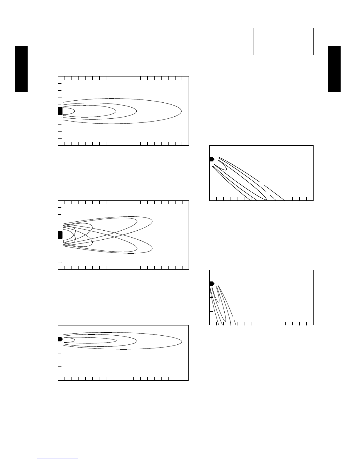
- (02-70) -
INDOOR UNIT
(SINGLE)
INDOOR UNIT
(SINGLE)
MODEL : ABG45LR
Note:
Condition
Fan speed : High
Operation mode : FAN
2 1 0.5 0.25
4
3
2
1
0
1
2
3
4
Unit : m/s(m)
(m)
TOP VIEW
VERTICA L FLAP : UPWARD
HORIZO NTAL FLAP : C ENTER
0 1 2 3 4 5 6 7 8 9 10 11 12 13 14 15 16 17 18
2
1
0.5
0.25
3
2
1
0
Unit : m/s(m)
(m)
SIDE VIE W
VERTICA L FLAP : CENTER
HORIZO NTAL FLAP : C ENTER
0 1 2 3 4 5 6 7 8 9 10 11 12 13 14
2
1
0.5
0.25
3
2
1
0
Unit : m/s(m)
(m)
SIDE VIE W
VERTICA L FLAP : DOWNWAR D
HORIZO NTAL FLAP : C ENTER
0 1 2 3 4 5 6 7 8 9 10 11 12 13 14
2
1
1
0.5
0.5
0.25
0.25
4
3
2
1
0
1
2
3
4
Unit : m/s(m)
(m)
TOP VIEW
VERTICA L FLAP : UPWARD
HORIZO NTAL FLAP : R IGHT AN D LEFT
0 1 2 3 4 5 6 7 8 9 10 11 12 13 14 15 16 17 18
2 1 0.5 0.25
3
2
1
0
Unit : m/s(m)
(m)
SIDE VIE W
VERTICA L FLAP : UPWARD
HORIZO NTAL FLAP : C ENTER
0 1 2 3 4 5 6 7 8 9 10 11 12 13 14 15 16 17 18
Page 96

- (02-71) -
INDOOR UNIT
(SINGLE)
INDOOR UNIT
(SINGLE)
MODEL : ABG54LR
Note:
Condition
Fan speed : High
Operation mode : FAN
2
1
0.5
0.25
3
2
1
0
Unit : m/s(m)
(m)
SIDE VIE W
VERTICA L FLAP : DOWNWAR D
HORIZO NTAL FLAP : C ENTER
0 1 2 3 4 5 6 7 8 9 10 11 12 13 14
2
1
0.5
0.25
3
2
1
0
Unit : m/s(m)
(m)
SIDE VIE W
VERTICA L FLAP : CENTER
HORIZO NTAL FLAP : C ENTER
0 1 2 3 4 5 6 7 8 9 10 11 12 13 14
2 1 0.5 0.25
4
3
2
1
0
1
2
3
4
Unit : m/s(m)
(m)
TOP VIEW
VERTICA L FLAP : UPWARD
HORIZO NTAL FLAP : C ENTER
0 1 2 3 4 5 6 7 8 9 10 11 12 13 14 15 16 17 2221201918
2
1
1
0.5
0.5
0.25
0.25
4
3
2
1
0
1
2
3
4
Unit : m/s(m)
(m)
TOP VIEW
VERTICA L FLAP : UPWARD
HORIZO NTAL FLAP : R IGHT AN D LEFT
212019180 1 2 3 4 5 6 7 8 9 10 11 12 13 14 15 16 17 22
2
1
0.5
0.25
3
2
1
0
Unit : m/s(m)
(m)
SIDE VIE W
VERTICA L FLAP : UPWARD
HORIZO NTAL FLAP : C ENTER
212019180 1 2 3 4 5 6 7 8 9 10 11 12 13 14 15 16 17 22
Page 97

- (02-72) -
INDOOR UNIT
(SINGLE)
INDOOR UNIT
(SINGLE)
AIR FLOW7-4-2.
MODEL : ABG36LR
Cooling
z
z
Heating
Fan speed
Number of
rotations
(r.p.m.)
Air ow
HIGH 110 0
m
3
/h 1900
l/s 528
CFM 1738
MED 910
m
3
/h 1500
l/s 417
CFM 883
LOW 750
m
3
/h 1200
l/s 333
CFM 706
QUIET 650
m
3
/h 1000
l/s 278
CFM 589
Fan speed
Number of
rotations
(r.p.m.)
Air ow
HIGH 110 0
m
3
/h 1900
l/s 528
CFM 1738
MED 910
m
3
/h 1500
l/s 417
CFM 883
LOW 750
m
3
/h 1200
l/s 333
CFM 706
QUIET 650
m
3
/h 1000
l/s 278
CFM 589
Page 98

- (02-73) -
INDOOR UNIT
(SINGLE)
INDOOR UNIT
(SINGLE)
MODEL : ABG45LR
Cooling
z
z
Heating
Fan speed
Number of
rotations
(r.p.m.)
Air ow
HIGH 1200
m
3
/h 2100
l/s 583
CFM 1236
MED 1000
m
3
/h 1700
l/s 472
CFM 1000
LOW 830
m
3
/h 1400
l/s 389
CFM 824
QUIET 680
m
3
/h 1100
l/s 306
CFM 647
Fan speed
Number of
rotations
(r.p.m.)
Air ow
HIGH 1200
m
3
/h 2100
l/s 583
CFM 1236
MED 1000
m
3
/h 1700
l/s 472
CFM 1000
LOW 830
m
3
/h 1400
l/s 389
CFM 824
QUIET 680
m
3
/h 1100
l/s 306
CFM 647
Page 99

- (02-74) -
INDOOR UNIT
(SINGLE)
INDOOR UNIT
(SINGLE)
MODEL : ABG54LR
Cooling
z
z
Heating
Fan speed
Number of
rotations
(r.p.m.)
Air ow
HIGH
136 0
m3/h
2300
l/s
639
CFM
135 4
MED
115 0
m3/h
1950
l/s
542
CFM
114 8
LOW
950
m3/h
1600
l/s
444
CFM
942
QUIET
790
m3/h
130 0
l/s
361
CFM
765
Fan speed
Number of
rotations
(r.p.m.)
Air ow
HIGH
134 0
m3/h
2300
l/s
639
CFM
135 4
MED
115 0
m3/h
1950
l/s
542
CFM
114 8
LOW
950
m3/h
1600
l/s
444
CFM
942
QUIET
790
m3/h
130 0
l/s
361
CFM
765
Page 100

- (02-75) -
INDOOR UNIT
(SINGLE)
INDOOR UNIT
(SINGLE)
FRESH AIR CHARACTERISTIC7-4-3.
MODEL : ABG36LR, ABG45LR, ABG54LR
Air ow volume - Static pressure of Fresh air intake characteristic
z
Installation
z
(Pa) 98
49
0
10
8
6
4
2
0
0 60 120 180 240 300 360 420
Fresh air ow (m
3
/h)
(mmAq)
Intake duct static pressure
For half concealed
installation
Fresh air inlet position
*1: Locally procured parts
Flexible duct *
1
UTD-RF204 (Optional parts)
 Loading...