

Fujitsu AB*30LBAG series, AB*36LBAG series, AO*45LJBYL series, AB*45LBAG series, AO*30LMBWL series Service Instruction
...Page 1

SPLIT TYPE
ROOM AIR CONDITIONER
Large Ceiling
type
Models Indoor unit Outdoor unit
AB*30LBAG
AB*36LBAG
AB*45LBAG
AO*30LMBWL
AO*36LMBWL
AO*45LJBYL
INVERTER
SERVICE
INSTRUCTION
R410A
Page 2

CONTENTS
1. SPECIFICATIONS
SPECIFICATIONS.......................................................................................................... 01-01
2. DIMENSIONS
DIMENSIONS.................................................................................................................. 02-01
3. REFRIGERANT SYSTEM DIAGRAM
REFRIGERANT CIRCUIT............................................................................................... 03-01
4. CIRCUIT DIAGRAM
CIRCUIT DIAGRAM........................................................................................................ 04-01
5. DESCRIPTION OF EACH CONTROL OPERATION
5-1-1 COOLING CAPACITY CONTROL......................................................................
5-1 COOLING OPERATION............................................................................................
5-4 AUTO CHANGEOVER OPERATION........................................................................
5-5 INDOOR FAN CONTROL.........................................................................................
5-6 OUTDOOR FAN CONTROL......................................................................................
5-7 LOUVER CONTROL.................................................................................................
05-01
05-01
5-2-1 HEATING CAPACITY CONTROL......................................................................
5-2 HEATING OPERATION.............................................................................................
05-02
05-02
5-3-1 INDOOR UNIT CONTROL.................................................................................
5-3 DRY OPERATION......................................................................................................
05-03
05-03
05-04
05-05
05-07
05-08
5-8 COMPRESSOR CONTROL......................................................................................
05-10
5-9 TIMER OPERATION CONTROL...............................................................................
05-11
5-10 ELECTRONIC EXPANSION VALVE CONTROL....................................................
05-13
5-11 TEST OPERATION CONTROL...............................................................................
05-13
5-12 PREVENT TO START FOR 3 MINUTES (3 MINUTES ST)....................................
05-13
5-13 4-WAY VALVE EXTENSION SELECT....................................................................
05-13
5-14 AUTO RESTART.....................................................................................................
05-13
5-15 PUMP DOWN (Refrigerant collecting operation).................................................
05-14
5-16 COMPRESSOR PREHEATING...............................................................................
05-14
5-17 DEFROST OPERATION CONTROL.......................................................................
05-14
5-19 VARIOUS PROTECTIONS......................................................................................
05-16
5-18 MANUAL AUTO OPERATION................................................................................
05-16
Page 3

6. REFRIGERANT CAUTION -R410A-
6-1 R410A TOOLS............................................................................................................ 06-01
6-2 PRECAUTION FOR INSTALLATION.........................................................................
06-02
6-3 PRECAUTION FOR SERVICING...............................................................................
06-04
6-4 NEW REFRIGERANT R410A.....................................................................................
06-05
6-5 DEFFERENCE FROM CONVENTIONAL MODEL (R22) AND PRECAUTIONS.......
06-08
8. APPENDING DATA
9. INSTALLATION MANUAL
8-1 CAPACITY TABLE..................................................................................................... 08-01
8-2 OPERATION RANGE.................................................................................................
08-02
8-3 ELECTRIC CHARACTERISTICS...............................................................................
08-03
8-4 SAFETY DEVICE........................................................................................................
08-04
8-5 FUNCTION SETTING.................................................................................................
08-05
7-1-2 OUTDOOR UNIT DISPLAY................................................................................
7-1-1 INDOOR UNIT DISPLAY....................................................................................
7-1 ERROR DISPLAY......................................................................................................
7. TROUBLE SHOOTING
7-2 TROUBLE SHOOTING WITH ERROR CODE..........................................................
7-3 TROUBLE SHOOTING WITH NO ERROR CODE....................................................
7-4 SERVICE PARTS INFORMATION............................................................................
07-01
07-01
8-5-1 INDOOR UNIT....................................................................................................
08-05
8-5-2 OUTDOOR UNIT (AO*30/ 36LMBWL)................................................................
08-07
8-5-3 OUTDOOR UNIT (AO*45LJBYL)........................................................................
08-09
07-02
07-21
07-03
07-26
Page 4

1-1-1 PARTS LAYOUT DRAWING...............................................................................
1-1-2 WIRING................................................................................................................
1-1-3 DISASSEMBLY PROCESS.................................................................................
1-1 For AO*30/ 36LMBWL.............................................................................................
1 REPLACEMENT PARTS ( For OUTDOOR UNIT ).......................................................
10. REPLACEMENT PARTS
10-01
10-01
10-01
10-04
10-03
2-1 PARTS LAYOUT DRAWING...................................................................................
2 REPLACEMENT PARTS ( For INDOOR UNIT )........................................................... 10-29
10-29
1-1-4 ASSEMBLY PROCESS of INVERTER UNIT.......................................................
10-09
1-2-1 PARTS LAYOUT DRAWING...............................................................................
1-2-2 WIRING................................................................................................................
1-2-3 DISASSEMBLY PROCESS.................................................................................
1-2-4 ASSEMBLY PROCESS of INVERTER UNIT......................................................
1-2 For AO*45LJBYL.....................................................................................................
10-14
10-14
10-18
10-16
10-24
Page 5

1 . SPECIFICATIONS
R410A
INVERTER
Large Ceiling type
Page 6
01-01
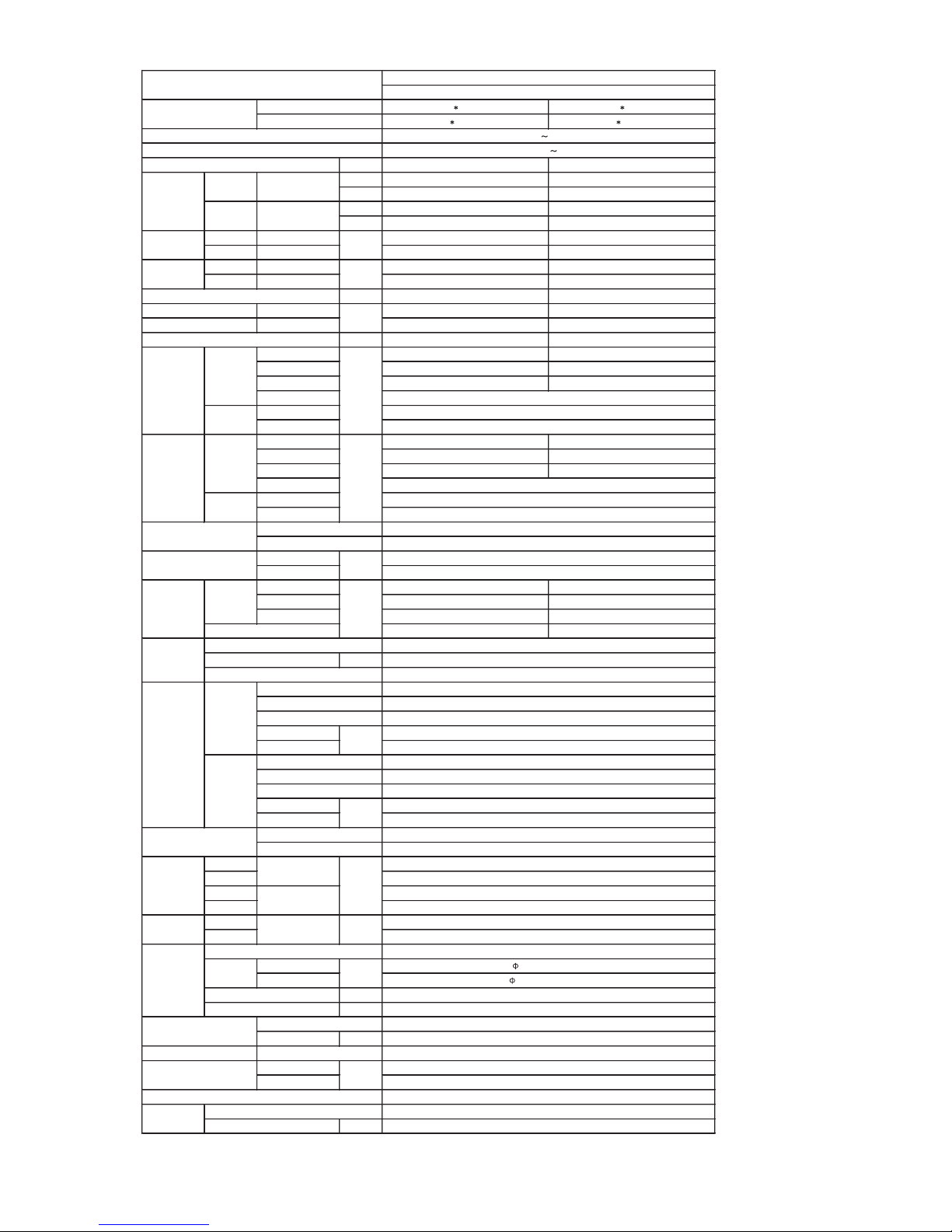
1. SPECIFICATIONS
AB 30LBAG AB 36LBAG
AO 30LMBW L AO 36LMBW L
EUROPEAN ENERGY LABEL COOLING C E
kW 8.50/10.00 10.0/11.20
BTU/h 29000/34100 34100/38200
kW 10.00/11.20 10.8/12.77
BTU/h 34100/38200 36900/43600
COOLING RATED/MAX 3.00/3.45 4.12/4.35
HEATING RATED/MAX 2.90/3.50 3.26/4.15
COOLING RATED/MAX 13.1/15.2 18.0/18.4
HEATING RATED/MAX 12.7/15.3 14.2/18.8
A 10 10
EER COOLING 2.83 2.43
COP HEATING 3.45 3.31
l/h (pints/h) 2.5 ( 5.3 ) 3.0 ( 6.3 )
High 1660 / 1660 1850 / 1850
Med 1500 / 1450 1660 / 1500
Low 1270 / 1150 1430 / 1270
Quiet
High
Low
High 1000 / 1000 1100 / 1100
Med 900 / 850 1000 / 900
Low 750 / 650 850 / 750
Quiet
High
Low
INDOOR
OUTDOOR
INDOOR
OUTDOOR
High 45.0 / 45.0 48.0 / 48.0
Med 42.0 / 42.0 45.0 / 45.0
Low 37.0 / 37.0 41.0 / 41.0
53.0 / 55.0 54.0 / 55.0
OUTPUT W
Rows × Stages
Fin Pitch
Coil Dimensions
Rows × Stages
Fin Pitch
Coil Dimensions
INDOOR
OUTDOOR
INDOOR
OUTDOOR
INDOOR
OUTDOOR
INDOOR
OUTDOOR
LIQUID
GAS
m
m
CHARGE g
COOLING
HEATING
mm
Note: Specifications are based on the following conditions.
Cooling: Indoor temperature of 27 °CDB / 19 °CWB,and outdoor temperature of 35 °CDB/24 °CWB.
Heating: Indoor temperature of 20 °CDB / 15 °CWB,and outdoor temperature of 7 °CDB/6 °CWB.
Pipe length : 7.5 m, Height difference : 0 m.(Outdoor unit - Indoor unit)
CEILING MODELS
INVERTER HEAT PUMP
230V 50Hz
STARTING METHOD
FAN TYPE x Q'ty
FAN MOTOR OUTPUT
W
COMPRESSOR
TYPE
FAN SPEED
COOL/HEAT
DRAIN PIPE
kg(lbs)
MATERIAL
SIZE
CONNECTION METHOD
SIZE
mm
WEIGHT
NET /
GROSS
MAX HEIGHT
HEAT
EXCHANGER
TYPE
INDOOR
Coil
OUTDOOR
Coil
Fin
mm
mm
PIPE
REFRIGERANT
REMOTE CONTROLLER TYPE
OPERATION(OUTDOOR)
°C
REFRIGERANT OIL
TYPE
TYPE
MAX LENGTH
CASING COLOR
DIMENSIONS
H × W × D
NET
dB(A)
OUTDOOR
mm
GROSS
NOISE LEVEL
(SOUND
PRESSURE)
COOL/HEAT
INDOOR
Fin
INDOOR
r.p.m
OUTDOOR
STARTING CURRENT
kW/kW
MOISTURE REMOVAL
AIR
CIRCULATION
COOL/HEAT
INDOOR
m3/h
OUTDOOR
INPUT POWER
kW
CURRENT
A
POWER SOURCE
AVAILABLE VOLTAGE RANGE
CAPACITY
COOLING
RATED/MAX
HEATING
RATED/MAX
TYPE
MODEL NAME
INDOOR
OUTDOOR
-
198-264V 50Hz
-
3600 / 3800
-
850 / 900
-
SIROCCO × 4
PROPELLER × 1
160
103
DC TWIN ROTARY (INVERTER)
1300
Inverter
Copper tube
Aluminium
3 × 12
1.45
252 × 1350 × 39.9
Copper tube
Aluminium
2 × 38
1.3
798 × 900 × 36.38
White (5Y9/0.5NN)
Beige (10YR7.5/1.0NN)
240 × 1660 × 700
830 × 900 × 330
318 × 1800 × 790
970 × 1050 × 445
48 / 61 ( 106 / 134 )
64 / 70 ( 141 / 154 )
FLARE
9.52 ( 3 / 8 inc.)
15.88 ( 5 / 8 inc.)
50 (chargeless:15)
30
R410A
2200
ABS
Outer diameter 25.6 / Inner diameter 22.0
POE
-10 to 43
-10 to 24
WIRELESS
Page 7
01-02
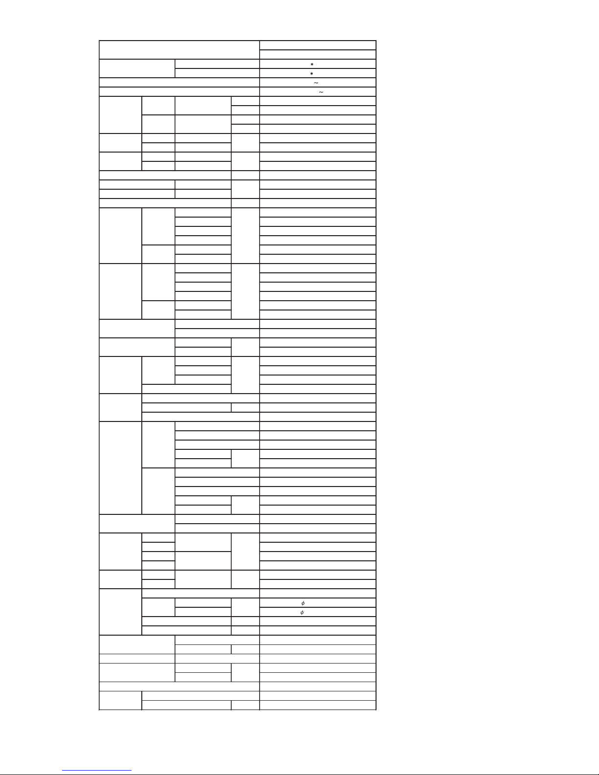
CEILING MODELS
INVERTER HEAT PUMP TYPE
AB 45LBAG
AO 45LJBYL
230V 50Hz
198-264V 50Hz
kW 12.5/14.0
BTU/h 42700/47800
kW 14.0/16.0
BTU/h 47800/54600
COOLING RATED/MAX 4.45/5.15
HEATING RATED/MAX 4.25/4.60
COOLING RATED/MAX 19.5/22.6
HEATING RATED/MAX 18.5/20.0
A 15
COOLING 2.81
HEATING 3.29
l/h (pints/h) 4.0(8.5)
High 2000/2000
Med 1850/1850
Low 1590/1590
Quiet -
High 6600/6600
Low -
High 1200/1200
Med 1100/1100
Low 950/950
Quiet -
High Upper fan : 850 , Lower fan : 750
Low -
INDOOR Sirocco × 4
OUTDOOR Propeller × 2
INDOOR 160
OUTDOOR 103 × 2
High 50/50
Med 47/47
Low 43/43
52/53
DC SCROLL(INVERTER)
OUTPUT W 2500
Inverter
Copper tube
Aluminium
3 × 12
Fin Pitch
1.45
Coil Dimensions
252 × 1350 × 39.9
Copper tube
Aluminium
2 × 60
Fin Pitch
1.3
Coil Dimensions
1260 × 900 × 36.38
INDOOR White(5Y9/0.5NN)
OUTDOOR Beige(10YR7.5/1.0NN)
INDOOR 240 × 1660 × 700
OUTDOOR 1290 × 900 × 330
INDOOR 318 × 1800 × 790
OUTDOOR 1430 × 1050 × 445
INDOOR 48/61 (106/134)
OUTDOOR 105/112 (231/247)
FLARE
LIQUID
9.52(3/8 inc.)
GAS
15.88(5/8 inc.)
m 70 (chargeless:20)
m 30
R410A
CHARGE g 3400
POE
COOLING
-15 to 43
HEATING
-15 to 24
WIRELESS
ABS
mm
Outer diameter 25.6 / Inner diameter 22.0
Note:
Specifications are based on the following conditions.
Cooling: Indoor temperature of 27 °CDB / 19 °CWB,and outdoor temperature of 35 °CDB/24 °CWB.
Heating: Indoor temperature of 20 °CDB / 15 °CWB,and outdoor temperature of 7 °CDB/6 °CW B.
Pipe length : 7.5 m, Height difference : 0 m.(Outdoor unit - Indoor unit)
DRAIN PIPE
MATERIAL
SIZE
WEIGHT
AIR
CIRCULATION
COOL/HEAT
m3/h
dB(A)
INDOOR
OUTDOOR
r.p.m
COMPRESSOR
FAN TYPE x Q'ty
Rows x Stages
PIPE
SIZE
mm
CONNECTION METHOD
MAX HEIGHT
MAX LENGTH
OUTDOOR
FAN MOTOR OUTPUT
W
STARTING METHOD
FAN SPEED
COOL/HEAT
NOISE LEVEL
(SOUND
PRESSURE)
COOL/HEAT
OUTDOOR
INDOOR
Coil
CURRENT
MOISTURE REMOVAL
INDOOR
TYPE
INDOOR
kW/kW
A
EER
COP
STARTING CURRENT
INDOOR
OUTDOOR
HEATING
kW
INPUT POWER
TYPE
MODEL NAME
POWER SOURCE
COOLING
RATED/MAX
AVAILABLE VOLTAGE RANGE
CAPACITY
RATED/MAX
DIMENSIONS
H × W × D
OUTDOOR
Coil
Fin
HEAT
EXCHANGER
TYPE
Fin
mm
Rows x Stages
mm
CASING COLOR
NET
GROSS
mm
kg(lbs)
NET /
GROSS
REMOTE CONTROLLER TYPE
TYPE
REFRIGERANT OIL
REFRIGERANT
TYPE
OPERATION(OUTDOOR)
°C
Page 8

2 . DIMENSIONS
R410A
INVERTER
Large Ceiling type
Page 9
02-01
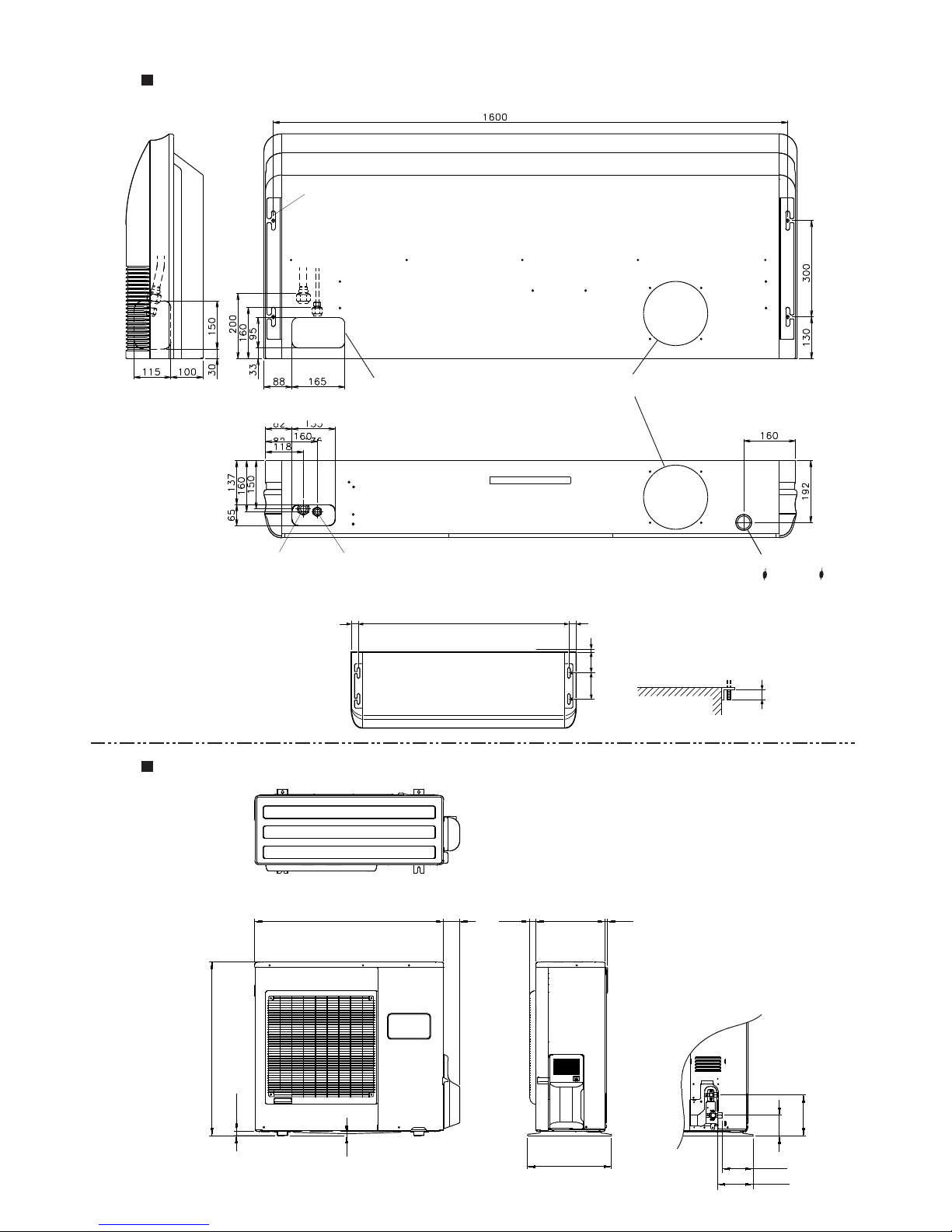
MODEL : AB*30/ 36LBAG
MODEL : AO*30/ 36LMBWL
(Unit : mm)
900
830
99
196
21
9
77
31 330
400
170
147
12
Top view
Front view
Side view
2. DIMENSIONS
Rear view
Side view
Bottom view
(Unit : mm)
30 30
Suspension bolt pitch
1,600
INDOOR UNIT (TOP VIEW)
10
155
300
INDOOR UNIT
Suspension bolt
should extend
outward 30 to 75.
Refrigerant piping
flare connection (Gas)
Refrigerant piping
flare connection (Liquid)
Drain piping connection
(Drain pipe : I.D. 22 O.D. 25.6)
Knock out hole for fresh air
Knock out hole for refrigerant piping
Hole for lifting bolt
(Use M10 screw bolt)
Page 10

02-02
MODEL : AB*45LBAG
MODEL : AO*45LJBYL
(Unit : mm)
900
1290
77 31
21
9
400
151
99
196
170
12
330
Top view
Side view
Front view
Rear view
Side view
Bottom view
(Unit : mm)
30 30
Suspension bolt pitch
1,600
INDOOR UNIT (TOP VIEW)
10
155
300
INDOOR UNIT
Suspension bolt
should extend
outward 30 to 75.
Refrigerant piping
flare connection (Gas)
Refrigerant piping
flare connection (Liquid)
Drain piping connection
(Drain pipe : I.D. 22 O.D. 25.6)
Knock out hole for fresh air
Knock out hole for refrigerant piping
Hole for lifting bolt
(Use M10 screw bolt)
Page 11

3 . REFRIGERANT SYSTEM DIAGRAM
R410A
INVERTER
Large Ceiling type
Page 12
03-01
Ø15.88mm(5/8")
Ø9.52mm(3/8")
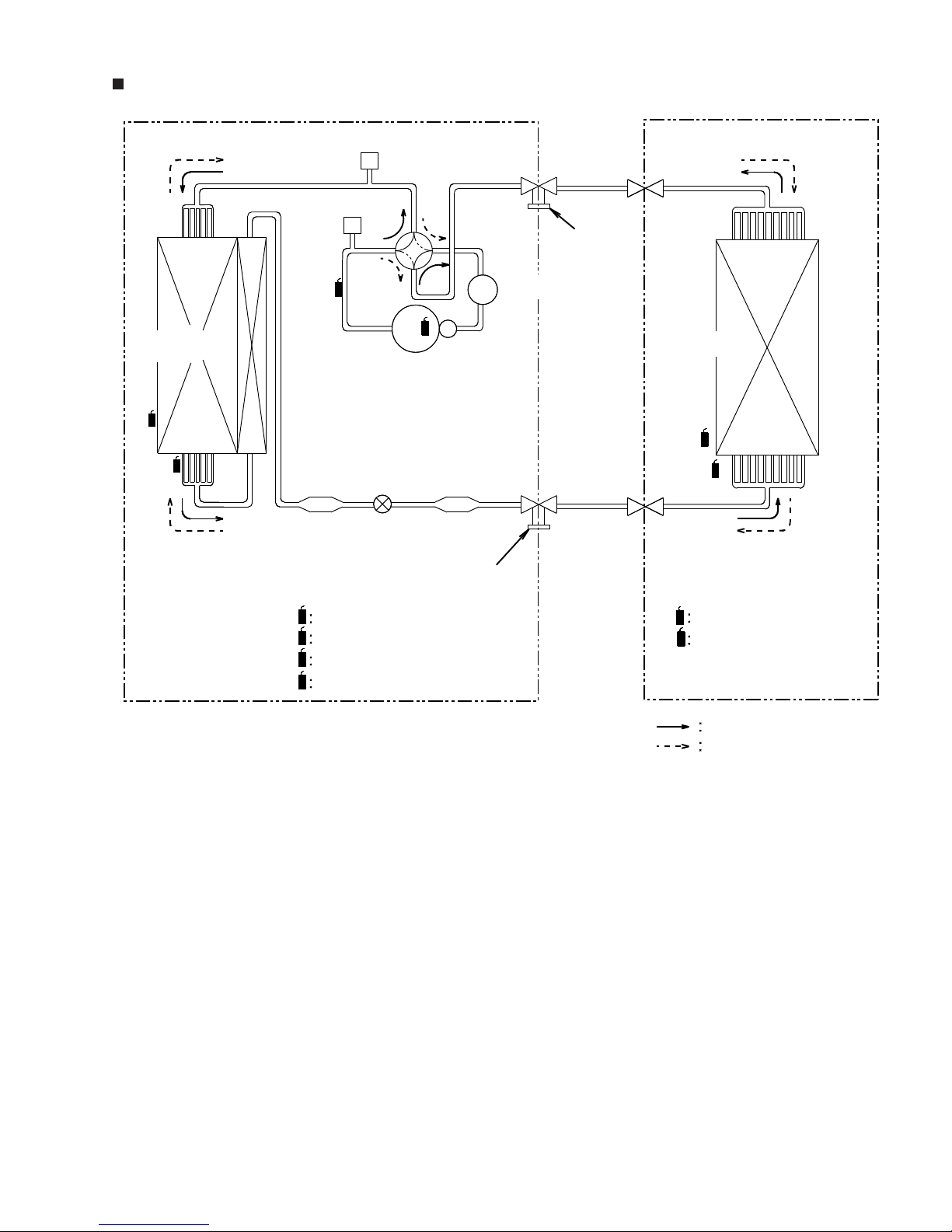
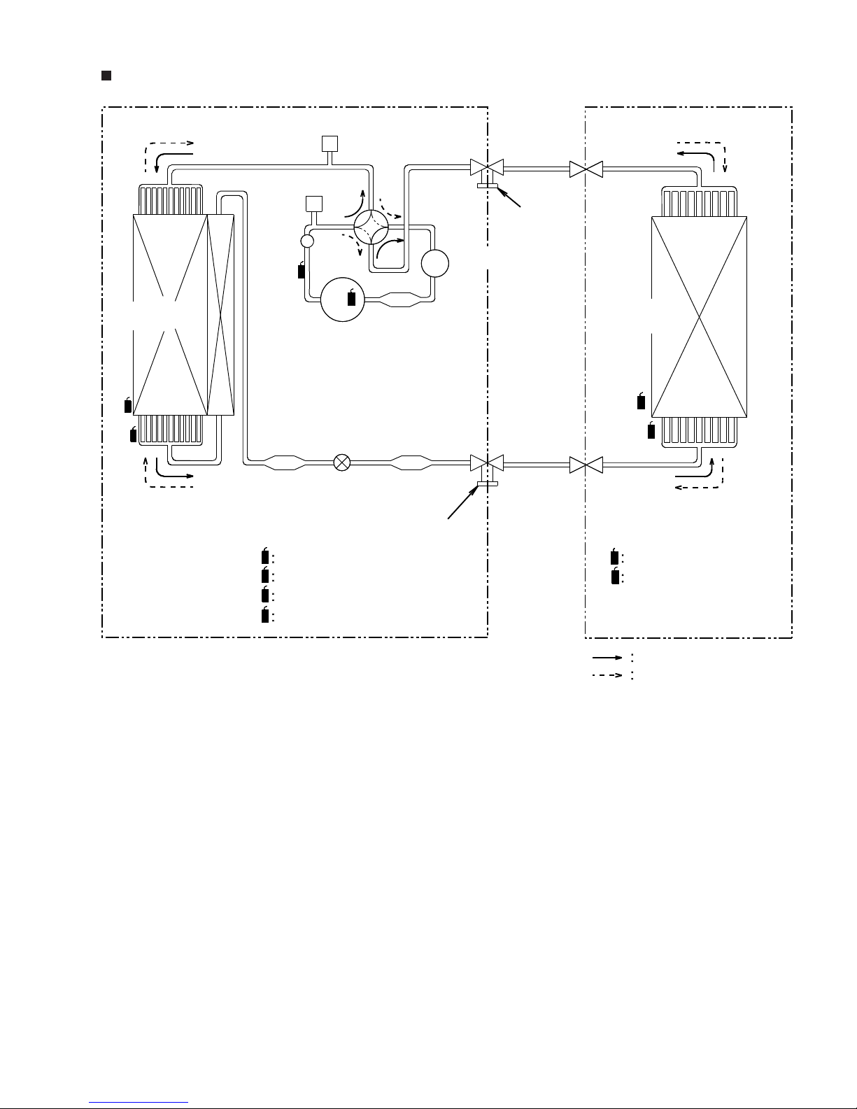
MODEL : AB*30/ 36LBAG / AO*30/ 36LMBWL
Outdoor Unit Indoor Unit
CONDENSER
HIGH PRESSURE
SWITCH
PRESSURE
CHECK VALVE
THO
THO
THC
THPO
THD
THR
THR
THPI
THPI
THD
THC
THPO
COMPRESSOR
ACCUMULATOR
EXPANSION
VALVE
STRAINERSTRAINER
4-Way
valve
THERMISTOR(DISCHARGE TEMP.)
THERMISTOR(ROOM TEMP.)
THERMISTOR(PIPE TEMP.)
THERMISTOR(OUTDOOR TEMP.)
THERMISTOR(PIPE TEMP.)
THERMISTOR(COMP TOP TEMP.)
Refrigerant Pipe
Refrigerant Pipe
COOL
HEAT
EVAPOLATOR
Charging Valve
Charging Valve
3. REFRIGERANT CIRCUIT
Page 13
03-02
Ø15.88mm(5/8")
Ø9.52mm(3/8")
MODEL : AB*45LBAG / AO*45LJBYL
Outdoor Unit Indoor Unit
CONDENSER
HIGH PRESSURE
SWITCH
PRESSURE
CHECK VALVE
THO
THO
THC
THPO
THD
THR
THPI
THR
THPI
THD
THC
THPO
COMPRESSOR
ACCUMULATOR
EXPANSION
VALVE
STRAINER
STRAINER STRAINER
4-Way
valve
THERMISTOR(DISCHARGE TEMP.)
THERMISTOR(ROOM TEMP.)
THERMISTOR(PIPE TEMP.)
THERMISTOR(OUTDOOR TEMP.)
THERMISTOR(PIPE TEMP.)
THERMISTOR(COMP TOP TEMP.)
Refrigerant Pipe
Refrigerant Pipe
COOL
HEAT
EVAPOLATOR
Charging Valve
Charging Valve
MUFFLER
Page 14

4 . CIRCUIT DIAGRAM
R410A
INVERTER
Large Ceiling type
Page 15

04-01
MODEL : AB*30/ 36/ 45LBAG
THERMISTOR(PIPE TEMP.)
THERMISTOR(ROOM TEMP.)
FAN MOTOR
CAPACITOR
FAN MOTOR
STEP MOTOR
(UP / DOWN)
STEP MOTOR
(LEFT / RIGHT)
BROWN
RED
GRAY
GRAY
BLACK
WHITE
WHITE
RED
BLACKBLACK
BLACK
ORANGE
YELLOW
WHITE
BROWN
RED
RED
ORANGE
YELLOW
WHITE
WHITE
BLACK
BLUE
BLUE
PURPLE
PURPLE
GRAY
GRAY
BROWN
RED
ORANGE
YELLOW
WHITE
GREEN
WHITE
WHITE
1
2
3
4
5
1
2
3
4
5
6
7
8
1
2
3
4
5
6
7
8
1
2
3
4
5
6
7
8
1
2
3
1
2
1
2
3
4
5
1
2
3
1
2
3
1
2
3
2
1
3
1
2
3
4
5
1
2
3
4
5
1 2
1 2 1 2
3 2 1
1 2
CN4
CN10
CN15CN13CN16CN5
CN11
CN7CN6
CN1
CN201
CN8
CONTROL BOARD
DISPLAY BOARD
N
L
FILTER
BOARD
Use T 3.15A 250V
Fuse on F101
4. CIRCUIT DIAGRAM
TO OUTDOOR UNIT
TERMINAL
3 2 1
Page 16
04-02
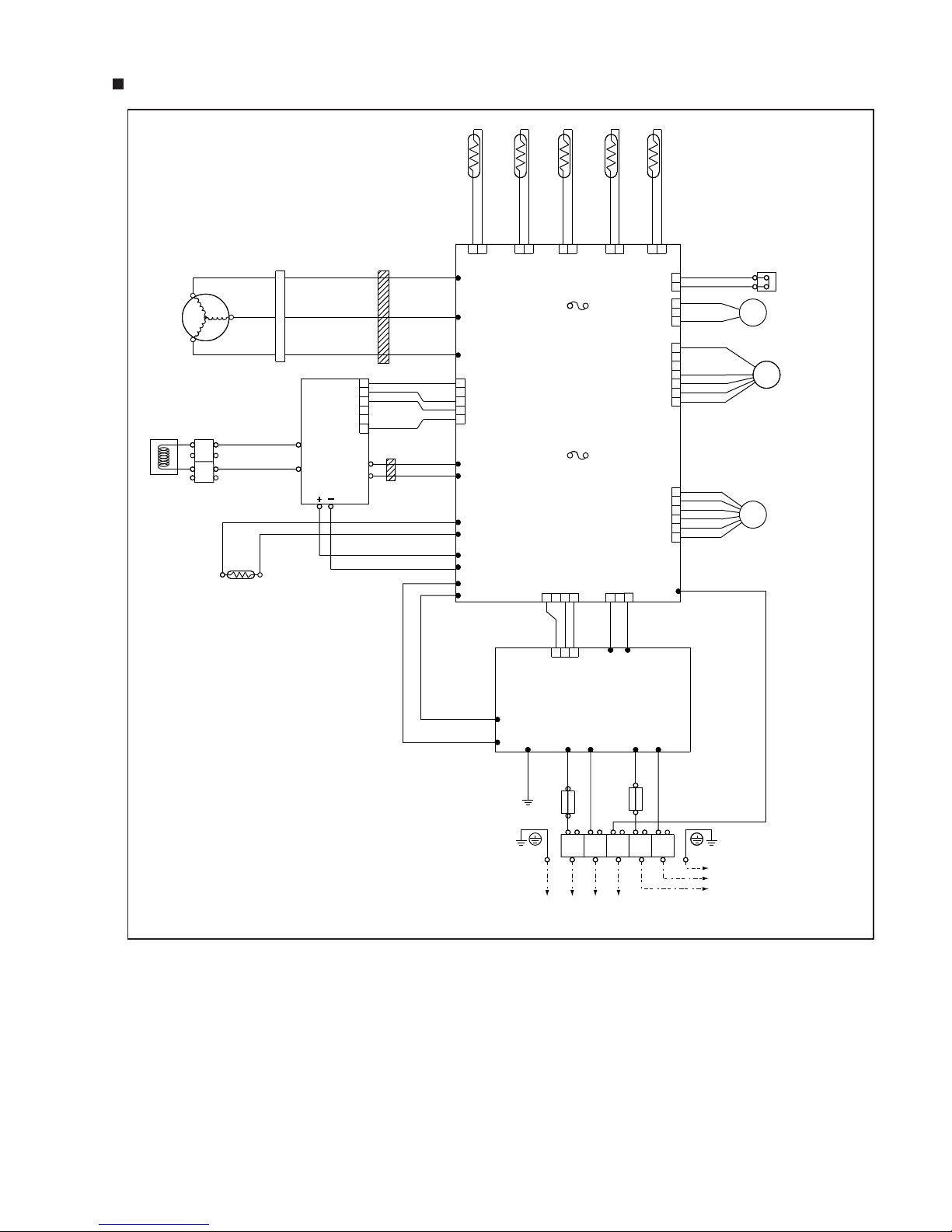
MODEL : AO*30/ 36LMBWL
CN21
U
W305
V
W304
W
W303
CN22 CN23 CN26 CN25
CN37
CN30
CN800
CN27
CN1
CN1
TM102
TM101
CN34
W9
W6W3 W7 W4 W5
W8
CN407
W12
W13
W21
W22
W200
W16
W17
W10
W11
1 2
1 2 3 4 1 2 3
1 2 3
1 2 1 2 1 2 1 2
BLACK
BLACK
WHITE
WHITE
GREEN
1 2(N) 3 L N
TO INDOOR UNIT
TO POWER SUPPLY
1
2
1
2
3
1
2
3
4
5
6
7
1
2
3
4
5
6
1
2
3
4
5
1
2
3
4
5
6
FUSE
F4 T 5A 250V
FUSE
F2 T 3.15A 250V
PRINTED
CIRCUIT
BOARD
(MAIN)
RED
BLACK
BLACK
BROWN
BLUE
BLACK
BROWN
BLACK
BLACK
WHITE
WHITE
YELLOW
YELLOW
BROWN
BROWN
BLUE
ORANGE
RED
RED
RED
RED
BLACK
WHITE
WHITE
BLACK
BLACK
ORANGE
BROWN
RED
REDRED
WHITEWHITE
BLACKBLACK
ORANGE
YELLOW
YELLOW
BLUE
WHITE
BROWN
ORANGE
RED
BLACK
BROWN
RED
4WV
FM
EV
HIGH PRESSURE SW
SOLENOID
COIL
EXPANSION
VALVE COIL
FAN MOTOR
THERMISTOR
(HEAT SINK)
THERMISTOR
(DISCHARGE)
THERMISTOR
(PIPE)
THERMISTOR
(OUTDOOR)
THERMISTOR
(COMPRESSOR)
PRINTED CIRCUIT
BOARD (FILTER)
EARTH
FUSE
10A
FUSE
25A
POSISTOR
TERMINAL
CHOKE
COIL
ACTIVE
FILTER
MODULE
L1
L2
P
N
EMI FILTER
2T
EMI FILTER
1T
CONNECTOR
COMPRESSOR
U
W
V
Page 17

04-03
MODEL : AO*45LJBYL
CN21
U
W305
V
W304
W
W303
CN22 CN23 CN26 CN25
CN37
CN30
CN800
CN801
CN27
CN1
CN1
TM102
TM101
CN34
W9
W6W3 W7 W1 W2
W8
CN407
W14
W15
W107
W108
W200
1 2
1 2 3 4 1 2 3
1 2 3
1 2 1 2 1 2 1 2
BLACK
BLACK
GRAY
RED
BLACK
GRAY
BLACK
WHITE
WHITE
GREEN
1 2(N) 3 L N
1
2
1
2
3
1
2
3
4
5
6
7
1
2
3
4
5
6
7
1
2
3
4
5
6
1
2
3
4
5
1
2
3
4
5
6
F4 T 5A 250V
F2 T 3.15A 250V
PRINTED
CIRCUIT
BOARD
(MAIN)
RED
BLACK
BLACK
BROWN
BLUE
BLACK
BROWN
BLACK
BLACK
WHITE
WHITE
YELLOW
YELLOW
BROWN
BROWN
BLUE
ORANGE
RED
RED
BLACK
WHITE
YELLOW
BROWN
RED
RED
RED
BLACK
WHITE
WHITE
WHITE
WHITE
BROWN
YELLOW
BLUE
VIOLET
BLACK
ORANGE
BROWN
RED
REDRED
WHITEWHITE
BLACKBLACK
ORANGE
YELLOW
ORANGE
BLACK
BROWN
RED
4WV
FM
FM
EV
HIGH PRESSURE SW
SOLENOID
COIL
EXPANSION
VALVE COIL
FAN MOTOR 1
FAN MOTOR 2
THERMISTOR
(HEAT SINK)
THERMISTOR
(DISCHARGE)
THERMISTOR
(PIPE)
THERMISTOR
(OUTDOOR)
THERMISTOR
(COMPRESSOR)
PRINTED CIRCUIT
BOARD (FILTER)
EARTH
FUSE
10A
POSISTOR
CHOKE
COIL
ACTIVE
FILTER
MODULE
L1
L2
P
N
EMI FILTER
1T
EMI FILTER
2T
EMI FILTER
2T
EMI FILTER
2T
EMI FILTER
3T
EMI FILTER
1T
CONNECTOR
COMPRESSOR
U
W
V
TERMINAL
TERMINAL
DIODE BRIDGE
RELAY
FUSE
TO INDOOR UNIT
TO POWER SUPPLY
Page 18

5 . DESCRIPTION OF EACH
CONTROL OPERATION
R410A
Large Ceiling type
INVERTER
Page 19
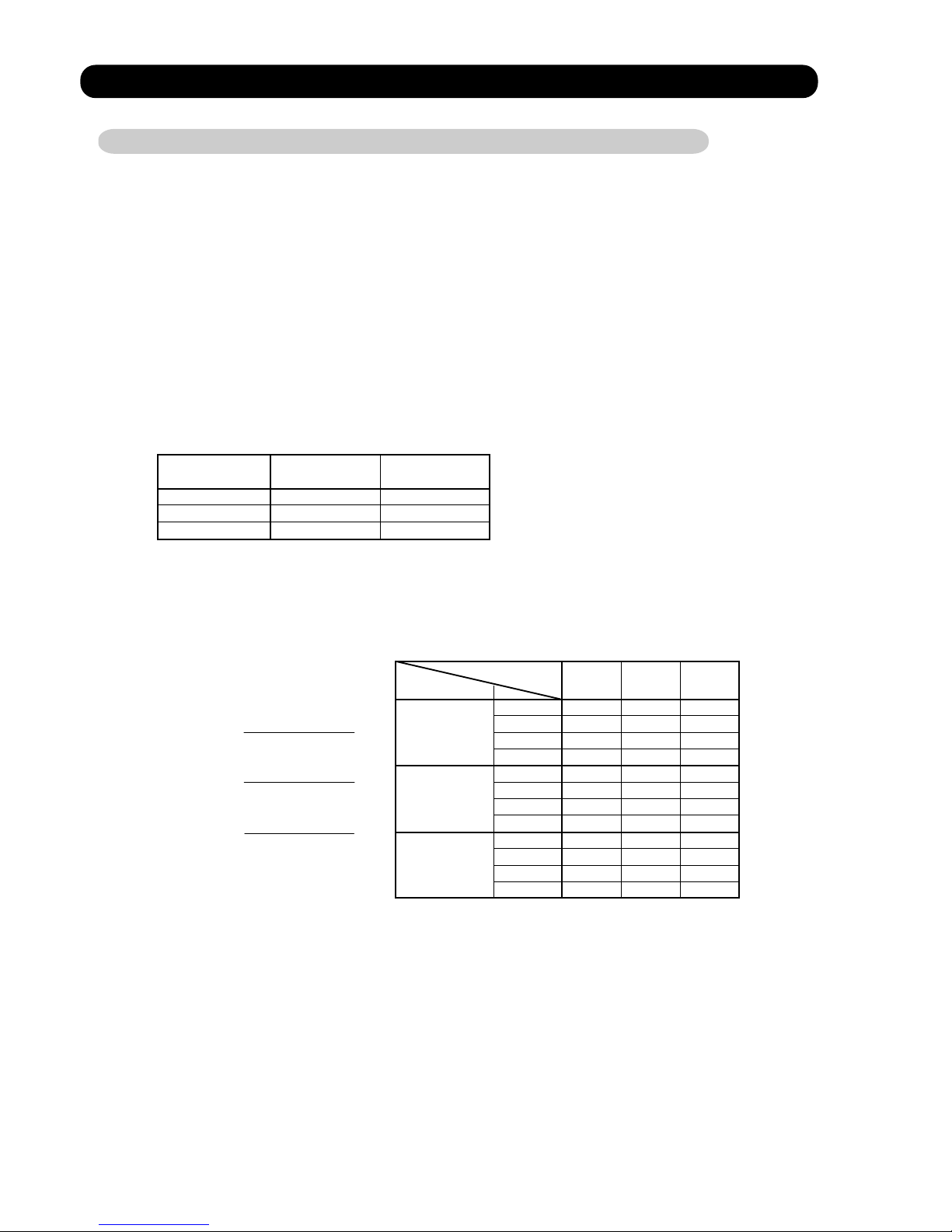
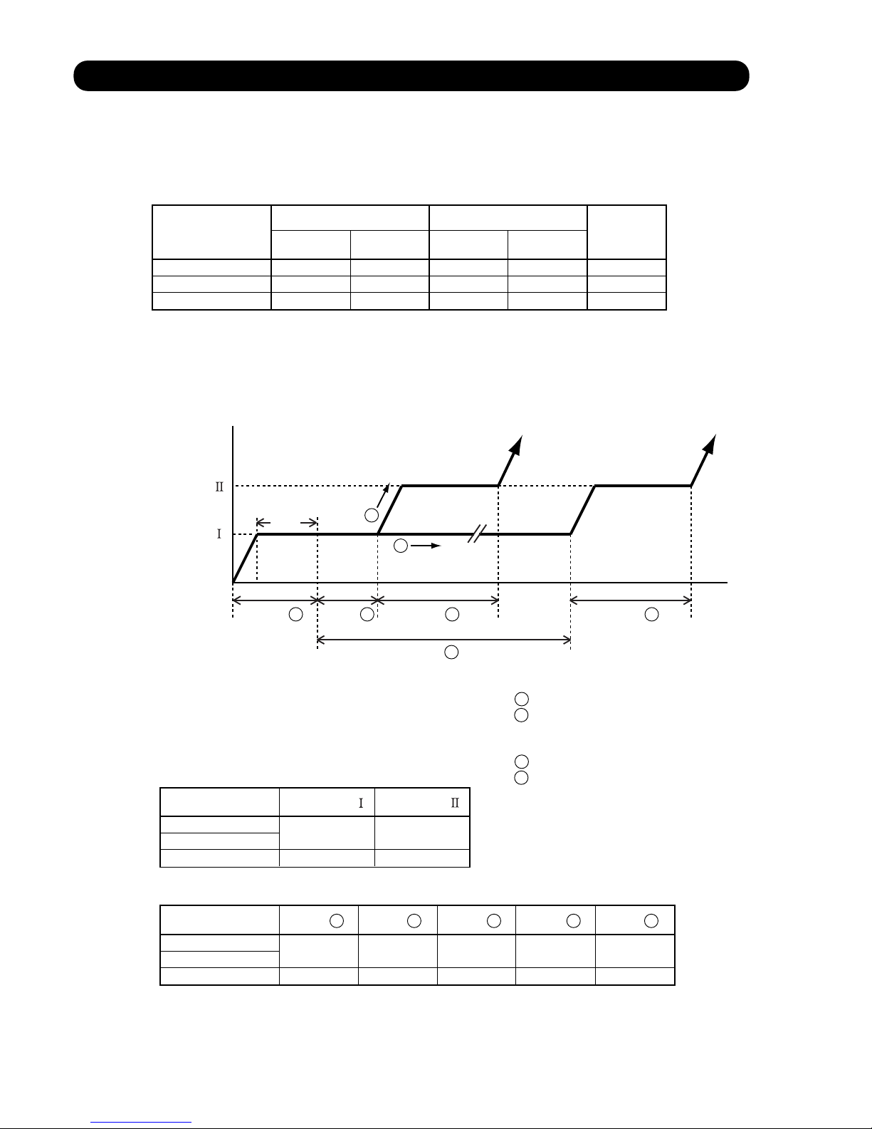
5-1. COOLING OPERATION
5-1-1 COOLING CAPACITY CONTROL
A sensor (room temperature thermistor) built in the indoor unit will usually perceive
difference or variation between a set temperature and present room temperature, and
controls the operation frequency of the compressor.
* If the room temperature is 2 degC higher than a set temperature,
the compressor operation frequency will attain to maximum performance.
* If the room temperature is 2 degC lower than a set temperature, the compressor
will be stopped.
* When the room temperature is between +2 degC to -2 degC of the setting temperature,
the compressor frequency is controlled within the range shown in Table1.
However, the maximum frequency is limited in the range shown in Figure 1 based on the
fan speed mode and the outdoor temperature.
minimum
frequency
maximum
frequency
20Hz
20Hz
20Hz
90Hz
90Hz
92Hz
AB*30LBAG
AB*36LBAG
AB*45LBAG
Outdoor air
temperature
A zone
31°C
B zone
C zone
D zone
Hi Me Lo
A zone
90Hz
70Hz
65Hz
55Hz
90Hz
92Hz
72Hz
60Hz
60Hz
75Hz
70Hz
65Hz
45Hz
75Hz
70Hz
65Hz
55Hz
72Hz
60Hz
45Hz
75Hz
70Hz
60Hz
60Hz
53Hz
53Hz
65Hz
70Hz
65Hz
70Hz
55Hz
72Hz
60Hz
65Hz
55Hz
55Hz
B zone
C zone
D zone
A zone
B zone
C zone
AB*30LBAG
D zone
A zone
B zone
C zone
AB*36LBAG
D zone
AB*45LBAG
19°C
11°C
( Table 1 : Compressor Frequency Range )
( Fig. 1 : Limit of Maximum Frequency based on Outdoor Temperature )
05-01
Fan speed mode
Page 20
5-2. HEATING OPERATION
5-2-1 HEATING CAPACITY CONTROL
A sensor (room temperature thermistor) built in the indoor unit will usually perceive
difference or variation between a set temperature and present room temperature, and
controls the operation frequency of the compressor.
* If the room temperature is lower 3 degC than a set temperature,
the compressor operation frequency will attain to maximum performance.
* If the room temperature is higher 2 degC than a set temperature, the compressor
will be stopped.
* When the room temperature is between +2 degC to -3 degC of the setting temperature,
the compressor frequency is controlled within the range shown in Table2.
However, the maximum frequency is limited in the range shown in Figure 2 based on
the outdoor temperature.
( Table 2 : Compressor Frequency Range )
( Fig.2 : Limit of Maximum Frequency based on Outdoor Temperature )
05-02
Outdoor air
temperature
C zone
B zone
A zone
A zone
95Hz
90Hz
80Hz
95Hz
90Hz
80Hz
92Hz
90Hz
80Hz
B zone
C zone
A zone
B zone
C zone
A zone
B zone
C zone
AB*30LBAG
AB*36LBAG
AB*45LBAG
16°C
12°C
Limit of Maximum
Frequency
minimum
frequency
maximum
frequency
20Hz
20Hz
20Hz
95Hz
95Hz
92Hz
AB*30LBAG
AB*36LBAG
AB*45LBAG
Page 21
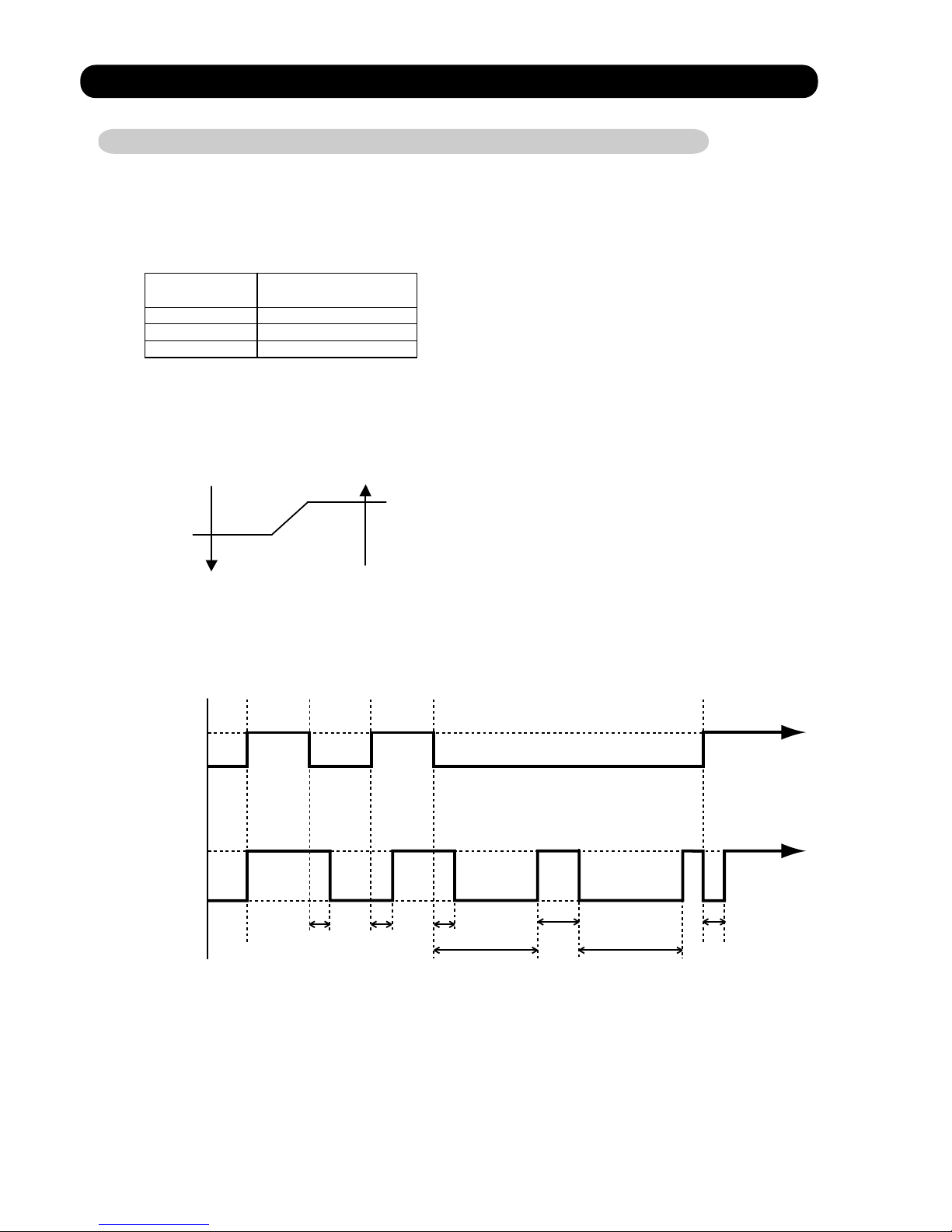
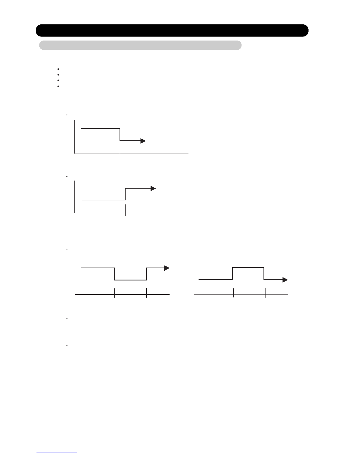
5-3. DRY OPERATION
5-3-1 INDOOR UNIT CONTROL
The compressor rotation frequency shall change according to set temperature and room
temperature variation which the room temperature sensor of the indoor unit has detected
as shown in the Table 3.
Room
temperature
Room
temperature
Compressor ON
Ts+1.5 degC
Ts+1 degC
Compressor OFF
Compressor
ON
ON
OFF
Indoor fan
air flow mode
Air flow mode : Lo
OFF
30 5 30 120 5 (sec)
180 180
( Table 3 : Compressor frequency )
( Fig.3 : Compressor Control based on Room Temperature )
( Fig.4 : Indoor Fan Control )
05-03
Operating frequency
45Hz
45Hz
30Hz
AB*30LBAG
AB*36LBAG
AB*45LBAG
Ts : Setting temperature
Page 22
5-4. AUTO CHANGEOVER OPERATION
When the air conditioner is set to the AUTO mode by remote control, operation starts in the optimum
mode from among the HEATING, COOLING and MONITORING modes. During operation, the
optimum mode is automatically swiched in accordance with temperature changes. The temperature
can be set between 18°C and 30°C in 1 degC steps.
When operation starts, only the indoor fan is operated for 1 minute. (Air flow mode: S- Lo)
After 1 minute, depends on the room temperature and outdoor unit's operarion mode,
the operation mode is selected in accordance with the table below.
( Table 4 : Operation mode selection table )
When COOLING was selected at , the same operation as COOLING OPERATION is performed.
When HEATING was selected at , the same operation as HEATING OPERATION is performed.
When the compressor was stopped for 6 consecutive minutes by the temperature control function
after the COOLING or HEATING operation mode was selected at above, operation is switched
to MONITORING and the operation mode is selected again.
1
1
2
3
1
4
1
05-04
Room temperature :TR
Operation mode
TR > Ts +2 degC
Ts +2 degC > TR
=
=
Ts +2 degC > TR > Ts -2 degC
Cooling
Monitoring
Heating
Ts : Setting temperature
Page 23
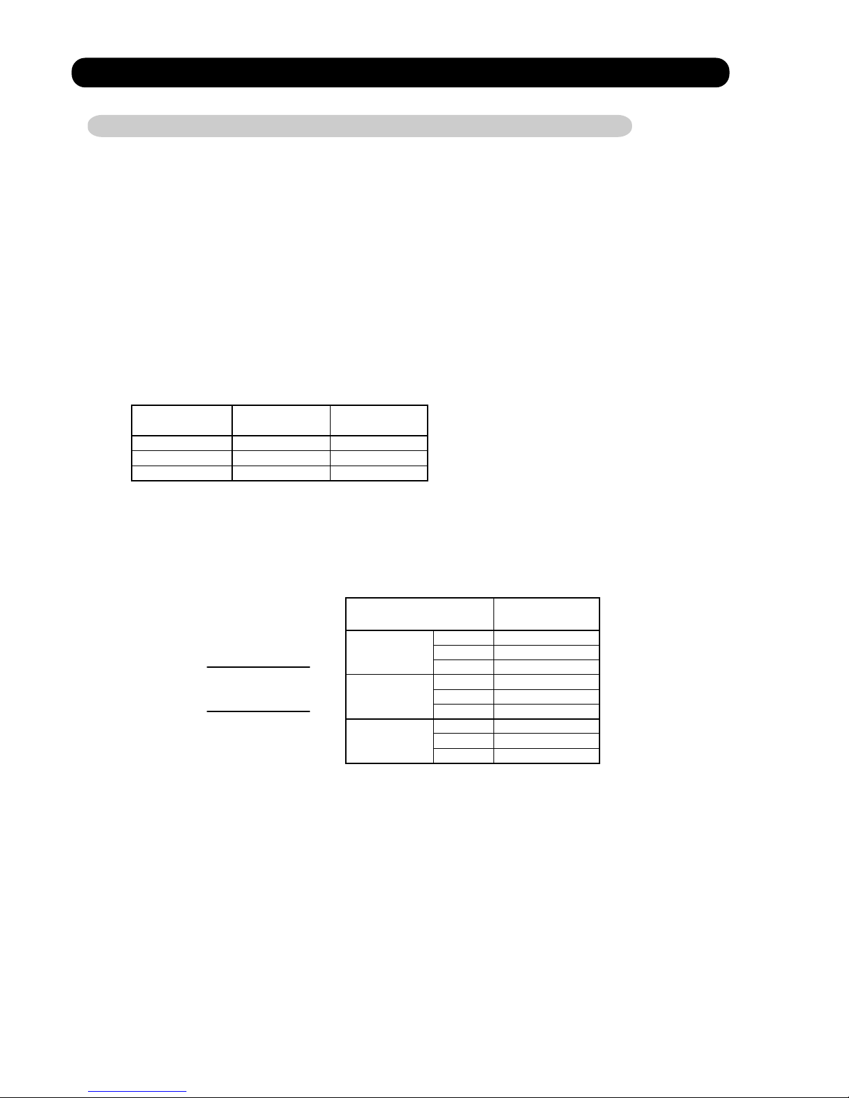
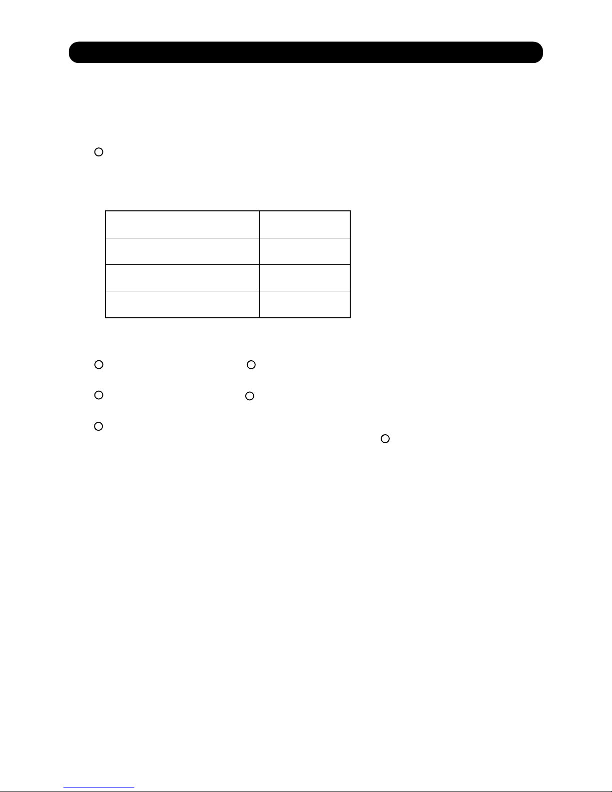
5-5. INDOOR FAN CONTROL
1. Fan speed
( Table 5 : Indoor Fan Speed )
Operation mode Air flow mode Speed (rpm)
Hi 1000
850
650
200
Me
Lo
Heating
S-Lo
2. FAN OPERATION
The airflow can be switched in 4 steps such as AUTO, LOW, MED, HIGH, while the indoor
fan only runs.
05-05
Hi 1000
850
650
200
Me
Lo
Cooling
S-Lo
Operation mode Air flow mode Speed (rpm)
Hi 1100
750
900
900
200
Me
Lo
Heating
S-Lo
Hi 1100
750
200
Me
Lo
Cooling
S-Lo
Operation mode Air flow mode Speed (rpm)
Hi 1200
1100
950
200
Me
Lo
Heating
S-Lo
Hi 1200
1100
950
200
Me
Lo
Cooling
S-Lo
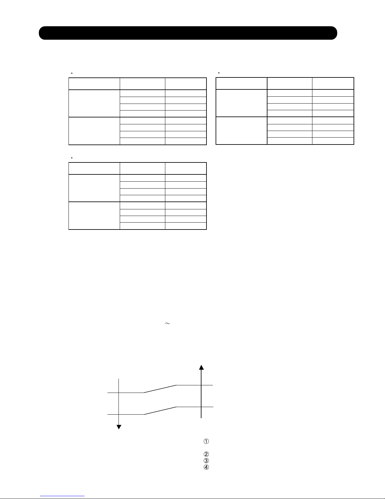
3. COOLING OPERATION
Switch the airflow [AUTO], and the indoor fan motor will run according to a room temperature,
as shown in Figure 5.
On the other hand, if switched in [HIGH] [LOW], the indoor motor will run at a constant airflow of [COOL]
operation modes LOW, MED, HIGH,as shown in Table 5.
( Fig.5 : Airflow change - over ( Cooling : AUTO ) )
When the room
temperature rises
When the room
temperature drops
TR : Room temperature
Ts : Setting temperature
TR-Ts > 2 degC
=
1 degC > TR-Ts
2 degC > TR-Ts > 1 degC
=
TR-Ts > 3 degC
=
2 degC > TR-Ts
3 degC > TR-Ts > 2 degC
=
HIGH mode
MED mode
LOW mode
*1
*1 : Contains a condition to the following
When the operation mode is set to AUTO mode
at the start of operation.
When the setting temperature was changed.
When the operation mode was changed to COOLING mode.
When the airflow mode was changed to AUTO mode.
When [AUTO] is selected, the indoor fan motor runs LO and OFF at 1 minute intervals.
AB*30LBAG
AB*36LBAG
AB*45LBAG
Page 24

05-06
4. HEATING OPERATION
When the airflow is set to [AUTO], the indoor fan
motor operates [MED] mode.
Then the indoor fan motor will run according
to a room temperature, as shown in Figure 6.
On the other hand, if switched in [HIGH] [LOW],
the indoor motor will run at a constant airflow
of [COOL] operation modes LOW, MED, HIGH,
as shown in Table 5.
5. COOL AIR PREVENTION CONTROL (Heating mode)
6. DRY OPERATION
Refer to the Figure 4.
During the dry mode operation, the fan speed setting can not be changed.
47°C
41°C
SETTING
FAN MODE
LO mode
S-LOW mode
33°C
30°C
30°C
Indoor heat exchanger
temperature
Indoor heat exchanger
temperature
Indoor heat exchanger
temperature
The maximum value of the indoor fan speed is set as shown in Figure 7, based on the detected
temperature by the indoor heat exchanger sensor on heating mode.
( Fig.6 : Airflow change - over ( Heating : AUTO ) )
( Fig.7 : Cool Air Prevention Control )
Hold
Go down one-step
Go up one-step
Page 25
5-6. OUTDOOR FAN CONTROL
1. Outdoor Fan Motor
Following table shows the fan speed of the outdoor unit.
*
The outdoor fan speed changs in the range mentioned avobe depending on the compressor
frequency and outdoor temperature.
(When the compressor frequency and outdoor temperature increase, the outdoor fan speed
also changes to the higher speed.
When the compressor frequency and outdoor temperature decrease, the outdoor fan
speed also changes to the lower speed.)
*
AB*45LBAG has two fan motors.
*
For AB*30/ 36LBAG
It runs at 500rpm for 20 seconds after starting up the outdoor fan.
When the outdoor heat exchanger tenperature is lower than 2°C,
the fan speed switches to 900rpm on heating mode.
For AB*45LBAG
It runs at 500rpm for 20 seconds after starting up the outdoor fan.
When the outdoor heat exchanger tenperature is lower than 2°C,
the fan speed switches to 850rpm(Upper fan) and 750rpm(Lower fan) on heating mode.
*
05-07
( Table 6 : Fan speed of the outdoor unit )
850/ 780/ 400/ 250/ 170 rpm
850/ 780/ 400/ 350/ 300 rpm
780/ 750/ 350/ 0 rpm
900/ 780/ 400/ 250/ 170 rpm
850/ 780/ 350/ 200/ 150 rpm
780/ 750/ 350/ 200/ 150 rpm
Cooling
Heating
AB*36LBAG
AB*30LBAG
AB*45LBAG
Upper fan
Lower fan
Page 26

5-7. LOUVER CONTROL
1. VERTICAL LOUVER CONTROL
Each time the button is pressed, the air direction range will
change as follows:
Use the air direction adjustments within the ranges shown above.
The vertical airflow direction is set automatically as shown, in accordance with the type of operation selected.
Cooling / Dry / Fan mode Horizontal flow
Heating mode Downward flow
(Function Range)
(Fig.8 : Air Direction Range)
(Operation Range)
1-2. SWING OPERATION
When the swing signal is received from the remote controller, the vertical louver starts to swing.
The range of swing depends on the set airflow direction.
When the indoor fan is either at S-Lo or Stop mode, the swinging operation is interrupted
and the louver stops at the memorized position.
05-08
The indoor fan motor starts after the louver reaches to the setting position.
At the start of operation if the setting louver position is or ,the setting position is set to or
after the louver moves from totally-enclosed position to . (Positioning Control)
( Stop mode means Operation stop.)
1
2
3
4
1 2 3 4
1
2
3
4
1
4
Cooling / Dry mode
Heating mode
Fan mode
1 2 3
1
1
2
2
3
4
(Swinging Range)
Airflow direction set
Range of swing
1
1
2
2
3
4
4
4
to
to
to
to
Page 27

2. HORIZONTAL LOUVER CONTROL
Each time the button is pressed, the air direction range will
change as follows:
Cooling / Dry mode
Heating mode
Fan mode
Use the air direction adjustments within the ranges shown above.
The horizontal airflow direction is set automatically on after initialization.
(Function Range)
(Fig.9 : Air Direction Range)
(Operation Range)
2-1. SWING OPERATION
When the swing signal is received from the remote controller, the horizontal louver starts to swing.
The range of swing depends on the set airflow direction.
When the indoor fan is either at S-Lo or Stop mode, the swinging operation is interrupted
and the louver stops at the memorized position.
05-09
( Stop mode means Operation stop.)
1 2 3 4 5
1 2 334 5
1
3
4
5
2
1
2
1
3
1
2
5
5
3
4
3
4
5
(Swinging Range)
Airflow direction set
Range of swing
to
to
to
to
1 5
to
Page 28
5-8. COMPRESSOR CONTROL
1. OPERATION FREQUENCY RANGE
The operation frequency of the compressor is different based on the operation mode as
shown in Table 7.
Cooling Heating
Min Max Min Max
Dry
(Table 7 : Compressor Operation Frequency Range)
2. OPERATION FREQUENCY CONTROL AT START UP
The compressor frequency soon after the start-up is controlled as shown in Figure 10.
(Fig.10 : Compressor Control at Start-up)
Frequency
Frequency
05-10
AB*30LBAG
20Hz
20Hz
20Hz
90Hz
90Hz
92Hz
AB*36LBAG
AB*45LBAG
20Hz
20Hz
20Hz
95Hz
95Hz
92Hz
45Hz
45Hz
30Hz
Time A Time B Time C
Time E
Time D
Hold
1
2
(Frequency)
(Time)
Frequency
Frequency
AB*30LBAG
AB*36LBAG
AB*45LBAG
180sec
60sec
120sec
120sec
720sec
180sec
80sec
180sec
180sec
720sec
40Hz
56Hz
56Hz
70Hz
AB*30LBAG
AB*36LBAG
AB*45LBAG
Time A Time B Time C Time D Time E
1 Discharge pipe temp. > 30°C
2 Discharge pipe temp. < 30°C
1 Discharge pipe temp. > 35°C
2 Discharge pipe temp. < 35°C
=
=
For AB*30/ 36LBAG
For AB*45LBAG
Page 29
5-9. TIMER OPERATION CONTROL
1. ON / OFF TIMER
OFF timer : When the clock reaches the set time, the air conditioner will be turned off.
Operation mode
Stop mode
Set time of timer
ON timer : When the clock reaches the set time, the air conditioner will be turned on.
Operation mode
Stop mode
Set time of timer
2. PROGRAM TIMER
05-11
AR- JW1
5-9-1 Wireless Remote Controller
ON / TIMER
OFF / TIMER
PROGRAM TIMER
SLEEP TIMER
The program timer allows the OFF timer and ON timer to be used in combination one time.
Operation mode
Operation will start from the timer setting (either OFF timer or ON timer)
whichever is closest to the clock's current timer setting.
The order of operations is indicated by the arrow in the remote control unit's display.
SLEEP timer operation cannot be combined with ON timer operation.
Stop mode
Stop mode
Stop mode
Operation mode
Operation mode
Set time
Set time Set time Set time
Page 30

05-12
3. SLEEP TIMER
If the sleep timer is set, the room temperature is monitored and the operation is stopped automatically.
If the operation mode or the set temperature is change after the sleep timer is set, the operation is
continued according to the changed setting of the sleep timer from that time ON.
Set temperature rises
( Ts : Set temperature )
Stop of operation
Set temperature lowers
( Ts : Set temperature )
Ts
Stop of operation
In the cooling operation mode
When the sleep timer is set, the setting temperature is increased 1 degC.
It increases the setting temperature another 1 degC after 1 hour.
After that, the setting temperature is not changed and the operation is stopped at the time
of timer setting.
Ts
+1degC
+2degC
-2degC
-1degC
-4degC
-3degC
Set
60min
In the heating operation mode
When the sleep timer is set, the setting temperature is decreased 1 degC.
It decreases the setting temperature another 1 degC every 30 minutes.
Upon lowering 4 degC, the setting temperature is not changed and the operation stops
at the time of timer setting.
Set
30min
30min
30min
Page 31

5-10. ELECTRONIC EXPANSION VALVE CONTROL
The most proper opening of the electronic expansion valve is calculated and controlled under the
present operating condition based on the following values.
The compressor frequency, the temperatures detected by the discharge temperature sensor
and the outdoor temperature sensor.
The pulse range of the electronic expansion valve control is between 50 to 480 pulses.
At the time of supplying the power to the outdoor unit, the initialization of the electronic
expansion valve is operated (1000 pulses are input to the closing direction).
5-11. TEST OPERATION CONTROL
The compressor won't enter operation status for 3 minutes after the compressor is stopped,
even if any operation is given.
At the time when the air conditioner is switched from the cooling mode to heating mode,
the compressor is stopped, and the 4-way valve is switched in 3 minutes later
after the compressor stopped.
When the power was interrupted by a power failure, etc. during operation, the operation contents
at that time are memorized and when power is recovered, operation is automatically resumed with
the memorized operation contents.
When the power is interrupted and recovered during timer operation, timer operation is canceled,
but only setting time is memorized.
[Operation contents memorized when the power is interrupted]
Operation mode
Set temperature
Set air flow
Timer mode and timer time
Air flow Direction
Swing
Thermistor detected position
5-12. PREVENT TO RESTART FOR 3 MINUTES ( 3 MINUTES ST )
5-13. 4-WAY VALVE EXTENSION SELECT
5-14. AUTO RESTART
05-13
Under the condition where the air conditioner runs, short two metal contacts under the battery
compartment lid, and the test operation control mode will appear.
During test running, the operation lamp and timer lamp of the air conditioner body twinkle simultaneously.
Set the test operation mode, and the compressor will continue to run regardless of whether the room
temperature sensor detects.
The test operation mode is released if 60 minutes have passed after setting up the test operation.
With Wireless Remote Controller
Page 32

05-14
AB*30LBAG
AB*36LBAG
AB*45LBAG
5-17. DEFROST OPERATION CONTROL
1. CONDITION OF STARTING THE DEFROST OPERATION
2. CONDITION OF THE DEFROST OPERATION COMPLETION
Defrost operation is released when the conditions become as shown in Table 10.
(Table 10 : Defrost Release Condition)
Release Condition
Outdoor heat exchanger temperature sensor value is higher than 12°C or
Compressor operation time has passed 15 minutes.
5-15. PUMP DOWN ( Refrigerant collecting operation )
When the product is stopped:
1. Press the PUMP DOWN switch (SW2) on the outdoor unit.
(The LED on the outdoor unit circuit board flickers every 1second.)
2. The pump down operation (cooling operation) begins right away.
After operation starts, close the 3-way valve (liquid).
3. After 2-3minutes, operation stops. Close the 3-way valve (gas) within 1minute after operations stops.
4. The LED will go out 3minutes after it stops. Disconnect the power supply after confirming that the LED has gone out.
When the product is operating:
1. Press the PUMP DOWN switch (SW2) on the outdoor unit. The LED on the outdoor unit circuit board flickers
every 1second, and operation stops.
At this point, recovery has not been completed, so do not close the 2 and 3-way valves.
2. The pump down operation (cooling operation) begins after 3minutes.
Close the 3-way valve (liquid) after operation starts.
3. After 2-3minutes, operation stops. Close the 3-way valve (gas) within 1minute after operations stops.
4. The LED will go out 3minutes after it stops. Disconnect the power supply after confirming that the LED has gone out.
Perform the following procedures to collect the refrigerant when moving the indoor unit or the outdoor unit.
When the outdoor heat exchanger temperature is lower than Operation temperature (Refer to Table 8) and the heating
operation has
been stopped for 3 hours, power is applied to the compressor and the compressor is heated.
(By heating the compressor, warm air is quickly discharged when operation is started.)
When operation was started, and when the outdoor temperature rises to Release temperature or greater,
preheating
is over.
5-16. COMPRESSOR PREHEATING
(Table 8 : Preheating Operation / Release Temperature)
Before 24 hour After 24 hour
Operation
temperature
Operation
temperature
Release
temperature
Release
temperature
3°C 7°C 0°C 4°C
The defrost operation starts when the outdoor heat exchanger temperature sensor detects
the temperature lower than the values shown in Table 9.
(Table 9 : Condition of starting Defrost Operation)
Less than 6 min. *1
or 10min. *2
AB*30LBAG
AB*36LBAG
AB*45LBAG
*3. Outdoor temp. > -1°C
*4. Outdoor temp. < -1°C
*2. Compressor stop time: Below 20min. Select 6min.
Above 20min. Select 10min.
After 6 min. *1
or 10min. *2
Compressor integrating
operation :Less than 45min.
Compressor integrating
operation :45min and over
-8°C *3
-10°C *4
-8°C *3
-10°C *4
Does not operate
Does not operate
=
Outdoor temp. Outdoor heat exchanger
temp.
Outdoor heat
exchanger temp.
12 degC
-20°C
*1. It means contiguous operation time.
Page 33

3. Defrost Flow Chart
The defrosting shall proceed by the integrating operation time and
outdoor heat exchanger temperature as follows.
05-15
(Not defrosted for 6 or 10 minutes)
3 sec later Compressor OFF
3 sec later Outdoor fan motor OFF
28 sec later 4-way valve OFF
34 sec later compressor ON
(Frequency : 92 Hz)
Outdoor fan motor : Low
Compressor : 30 Hz
4-way valve OFF
Outdoor fan motor OFF
Compressor ON
(Frequency : 92 Hz)
Heating operation start : Compressor ON
Defrost start
Defrost Indicator:
[Operation lamp]
9 sec ON / 1 sec OFF
Outdoor heat exchanger temperature: Over 12°C
or
Compressor ON time: Over 15 minutes
Defrost end
Compressor integrating
operation:
45 minutes and over
Outdoor heat exchanger
temperarure:
Below -10°C
Outdoor heat exchanger
temperarure:
Below -8°C
Outdoor temp. > -1°C
=
Outdoor temp. < -1°C
Compressor integrating
operation:
45 minutes and over
Outdoor temp Outdoor heat exchanger
temperature:
Above 12 degC
Outdoor heat exchanger
temperarure:
Below -10°C
Outdoor heat exchanger
temperarure:
Below -20°C
Outdoor heat exchanger
temperarure:
Below -8°C
Outdoor temp. > -1°C
=
Outdoor temp. < -1°C
AB*30/ 36LBAG
AB*45LBAG
Defrost start
Defrost Indicator:
[Operation lamp]
9 sec ON / 1 sec OFF
5
Page 34

05-16
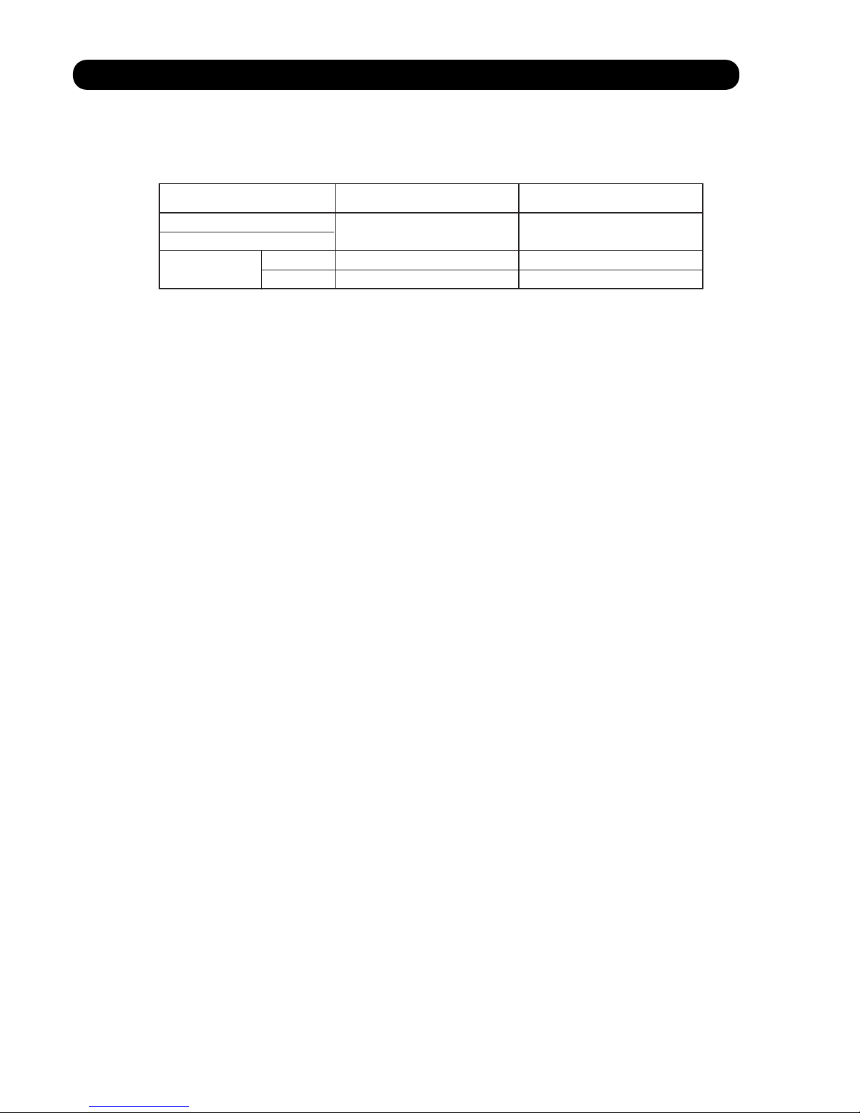
5-18. MANUAL AUTO OPERATION
If MANUAL AUTO Button is set, the operation is controlled as shown in Table 11.
If the remote control is lost or battery power dissipated, this function will work without the remote control.
OPERATION MODE
Auto changeover
FAN CONT. MODE
Auto
TIMER MODE
Continuous (No timer setting available)
SETTING TEMP.
23°C
SETTING LOUVER
Standard
SWING
OFF
(Table 11 : Manual auto operation )
5-19. VARIOUS PROTECTIONS
1. DISCHARGE GAS TEMPERATURE OVER RISE PREVENTION CONTROL
The discharge gas thermosensor (discharge thermistor : Outdoor side) will detect discharge gas
temperature.
When the discharge temperature becomes higher than Temperature ,the compressor frequency
is decreased 10 Hz, and it continues to decrease the frequency for 10 Hz every 120 seconds until
the temperature becomes lower than Temperature .
When the discharge temperature becomes lower than Temperature ,the control of the compressor
frequency is released.
When the discharge temperature becomes higher than Temperature ,the compressor stops.
When the discharge temperature becomes lower than Temperature ,the compressor operates.
(Table 12 : Discharge Temperature Over Rise Prevention Control / Release Temperature)
Temperature Temperature Temperature Temperature
AB*30LBAG
AB*36LBAG
AB*45LBAG
110°C 105°C 120°C 80°C
Page 35

2. CURRENT RELEASE CONTROL
05-17
[ Heating ]
AB*45LBAG
T0 > 12°C
T0 < 12°C
=
T0: Outdoor temperature
780 rpm850 rpm 350 rpm 200 rpm 150 rpm
23.5A / 23.0A 20.0A / 19.5A
23.5A / 23.0A 23.5A / 23.0A 23.5A / 23.0A 23.5A / 23.0A
20.0A / 19.5A 15.0A / 14.5A 12.0A / 11.5A
Outdoor unit fan speed
[ Cooling ]
AB*45LBAG
T0 > 45°C
=
T0: Outdoor temperature
780 rpm850 rpm 400 rpm 350 rpm 300 rpm
12.0A / 11.5A
20.0A / 19.5A 20.0A / 19.5A
23.5A / 23.0A
12.0A / 11.5A 12.0A / 11.5A
18.0A / 17.5A
20.0A / 19.5A
12.0A / 11.5A
18.0A / 17.5A
12.0A / 11.5A
15.0A / 14.5A
18.0A / 17.5A
Outdoor unit fan speed
[ Cooling ]
AB*30LBAG
AB*36LBAG
T0 > 45°C
T0 < 0°C
T0 < 13°C
45°C > T0 > 38°C
=
=
45°C > T0 > 38°C
=
38°C > T0 > 31°C
=
31°C > T0 > 25°C
=
25°C > T0 > 19°C
=
19°C > T0 > 13°C
=
13°C > T0 > 0°C
=
19°C > T0 > 13°C
=
38°C > T0 > 19°C
=
T0: Outdoor temperature
780 rpm850 rpm 400 rpm 250 rpm 170 rpm
10.0A / 9.5A
14.0A / 13.5A 14.0A / 13.5A
15.0A / 14.5A
18.0A / 17.5A
10.0A / 9.5A 10.0A / 9.5A
15.0A / 14.5A
7.0A / 6.5A
12.0A / 11.5A
5.5A / 5.0A
7.0A / 6.5A
9.5A / 9.0A
Outdoor unit fan speed
The compressor frequency is controlled so that the outdoor unit input current does not exceeds
the current limit value that was set up with the outdoor temperature.
The compressor frequency returns to the designated frequency of the indoor unit at the time
when the frequency becomes lower than the release value.
(Table 13 : Current Release Operation Value / Release Value)
[ Heating ]
AB*30LBAG
AB*36LBAG
T0 > 16°C
T0 < 5°C
16°C > T0 > 5°C
=
=
T0: Outdoor temperature
780 rpm900 rpm 400 rpm 250 rpm 170 rpm
15.0A / 14.5A 15.0A / 14.5A
18.0A / 17.5A 18.0A / 17.5A 18.0A / 17.5A18.0A / 17.5A
13.0A / 12.5A 10.0A / 9.5A 8.0A / 7.5A
18.0A / 17.5A
Outdoor unit fan speed
Page 36

3. ANTI-FREEZING CONTROL (Cooling mode)
The compressor frequency decreases on cooling mode when the indoor heat exchanger
temperature sensor detects the temperature lower than 3°C.
Then, the anti-freezing control is released when it becomes higher than 6°C.
(Fig.11 : Anti-freezing Protection Operation / Release Temperature)
4. COOLING PRESSURE OVER RISE PROTECTION
When the outdoor unit heat exchange sensor temperature rises to 70.5°C or greater,
the compressor is stopped and error display is indicated.
Indoor heat exchange
temperature
5. HIGH TEMPERATURE RELEASE CONTROL ( HEATING MODE )
On heating mode, the compressor frequency is controlled as following based on the
detection value of the indoor heat exchanger temperature sensor.
(Fig.12 : Heating Overload Protection Control)
05-18
63°C
54°C
50°C
Compressor is OFF
The compressor frequency is
decreased 10Hz every 60seconds.
Compressor OFF :
Release of protection
Compressor ON :
The compressor frequency is
increased 10Hz every 60seconds.
Hold
Indoor heat exchange
temperature
3°C
6°C
12°C
The compressor frequency is
decreased 10Hz every 120seconds.
Compressor OFF : Hold
Compressor ON : Release of protection
Hold
Release of protection
When the compressor frequency becomes lower than minimum frequency,
the compressor operates at minimum frequency.
If the indoor heat exchanger temperature sensor detects the temperature lower than
3°C after 2minutes upon operating the compressor at minimum frequency,
the compressor stops.
Page 37

6 . REFRIGERANT CAUTION -R410A-
R410A
INVERTER
Large Ceiling type
Page 38

6-1. R410A TOOLS
Gauge manifold . . . . . . . . . . . . . . . . . . . . . (Fig.4-1)
Since the normal pressure is high, the connection pipe size
is also different.
Charge hose . . . . . . . . . . . . . . . . . . . . . . . (Fig.4-2)
Refrigerant cylinder . . . . . . . . . . . . . . . . . (Fig.4-3)
Confirm the refrigerant type before charging. Always
charge liquid-phase refrigerant.
Electronic balance for refrigerant
charging . . . . . . . . . . . . . . . . . . . . . . . . . . . (Fig.4-4)
Electronic balance is recommended as in the case of
R410A.
Vacuum pump with adapter to prevent
reverse flow . . . . . . . . . . . . . . . . . . . . . . . .(Fig.4-5)
Conventional pump can be used.
Vacuum holder . . . . . . . . . . . . . . . . . . . . . (Fig.4-6)
Conventional pump can be used if adapter for preventing
vacuum pump oil from flowing back is used.
Gas leakage tester . . . . . . . . . . . . . . . . . . (Fig.4-7)
Exclusive for HFC
Refrigerant cleaner . . . . . . . . . . . . . . . . . . (Fig.4-8)
Brown paint as designated by the ARI, USA
Flare tool . . . . . . . . . . . . . . . . . . . . . . . . . . (Fig.4-9)
Torque wrench . . . . . . . . . . . . . . . . . . . . (Fig.4-10)
Refrigerant recovering
equipment (Collector) . . . . . . . . . . . . . . (Fig.4-11)
The type which can be used for any refrigerant is available
Nitrogen cylinder . . . . . . . . . . . . . . . . . . . (Fig.4-12)
This prevents an oxide film from forming in the pipe silveralloy brazing work by turning the air out of the pipe and
preventing the inside combustion.
Safety charger . . . . . . . . . . . . . . . . . . . . . (Fig.4-13)
It is always compulsory to change the liquid, because
R410A is a mixed refrigerant and there is some fear that a
mixing ratio changes. In order to avoid the refrigerant from
returning to the compressor in a liquid state, the refrigerant
can be charged instead of giving a load to the compressor
with a safety charger.
Control valve . . . . . . . . . . . . . . . . . . . . . . (Fig.4-14)
The control valve prevents the refrigerant from spouting
when it is removed, as the charging hose side and the service port side are possible to open and close at the same
time.
Thermistor vacuum gauge . . . . . . . . . . . (Fig.4-15)
To remove moisture from the refrigerating cycle completely, it is necessary to perform appropriate vacuum drying.
For that reason, vacuum conditions can be confirmed certainly.
Vacuum valve . . . . . . . . . . . . . . . . . . . . . (Fig.4-16)
This valve builts in a check valve, and it is easily possible
to vacuum a refrigerating cycle or check for degree of vacuum with it.
TOOLS AND EQUIPMENT (R410A)
Gauge Manifold
R410A
R22, R407C
High
pressure
gauge
Compond
gauge
Port size
-0.1 5.3
Mpa
-0.1 3.8
Mpa
1/2UNF
5/16"
-0.1 3.5
Mpa
-0.1 1.7
Mpa
7/16UNF
1/4"
*
1
Charge hose
R410A
R22, R407C
Normal
pressure
Port size
5.1 Mpa
27.4 Mpa
1/2UNF
3.4 Mpa
17.2 Mpa
7/16UNF
*
2
Breaking
pressure
This air conditioner used R410A.
For installation and servicing, it is necessary to prepare the
tools and machines that are different from the previous
refrigerant.
Mark shows the exclusive use for R410A.
The specification of the gauge is different due
to higher pressure.
The size of connection pipe is also different to
prevent mis-use.
The shape of flare is different for
high pressure condition.
06-01
Gas charging
Vacuuming
Piping work
Pressure control and
Circuit switching
Charge hose
Fig.4-2
Outdoor unit
Electronic charging
scale Fig.4-4
Vacuum pump Fig.4-5
Thermistor vacuum gauge Fig.4-15
Vacuum
Valve Fig.4-16
Safety charger Fig.4-13
Control Valve
Fig.4-14
Vacuum holder Fig.4-6
Leakage tester Fig.4-7
Cleaner Fig.4-8
Collector Fig.4-11
Nitrogen Cylinder
Fig.4-12
Torque wrench
Fig.4-10
Flare tool
Fig.4-9
Gauge manifold
Fig.4-1
Fig.4-3
Refrigerant cylinder
Vacuum control
Low pressure
High pressure
side
side
6. REFRIGERANT CAUTION -R410A-
Page 39

6-2. PRECAUTION FOR INSTALLATION
06-02
Precaution for installation
The pipe must be properly pressure rated for R410A
The pipe must be an air-conditioning refrigerant pipe.
Flare and flare nuts
Diameter 1/4 ” (6.35mm) 3/8 ” (9.52mm) 1/2” (12.7mm)
Refrigerant
R410A
R22
/R407C
R410A R410A
A 9.1 9.0 13.2 13.0 16.6
16.2
B 13 12 20 15 13 20
C 12 11 16 12.5 19 16
Nut width 17 22 26 24
Always use the flare nut that is packed
with the product.
Do not use existing (for R22) pipes
•
Be sure to use new pipes when replacing
conventional (R22) model with HFC
(R407C, R410A) model.
•
If you use existing pipes, it may cause
resolution of compressor oil by remaining
mineral oil.
3/8” (15.88mm)
R410A
22
29
19.7
25
R22
/R407C
R22
/R407C
R22
/R407C
19.4
23
20
27
3/4” (19.05mm)
R410A
24
36
24
29
R22
/R407C
23.7
29
24
Material
Nominal diameter
(in)
1/4" 3/8" 1/2" 5/8" 3/4" 7/8" 1 1/8" 1 1/4" 1 1/2"1 3/8"1"
6.35 9.52 12.70 15.88 19.05 22.22 28.58 31.75 38.1034.9225.40
Outside diameter
(mm)
Wall thickness
(mm)
0.8 0.8 0.8 1.0 1.2 1.0 1.0 1.1 1.31.21.0
1) Allowable tensile stress 33 (N/mm );
>
=
2
2) Allowable tensile stress 61 (N/mm ); 3) Design pressure 4.2MPa.
>
=
2
JIS H3300-C1220T-H or equivalent
2)
COPPER
JIS H3300-C1220T-O or equivalent
1)
COPPER
3)
Pipe diameter, recommended material and wall thickness
A
C
B
Page 40

Be careful not to mix moisture and
contamination into the pipe
Moisture and contamination
in the pipe is a cause of
trouble.
Air purge
Always use a
vacuum pump
to purge air.
Refrigerant charge
Do it always from the liquid phase
side.
Don't charge from the gas phase side.
Compressor oil is changed
Be careful to handle synthetic oil, since it
resolves easily by moisture and
contamination.
Don't mix new synthetic oil and mineral oil.
It may cause trouble.
We developed new synthetic oil, since HFC
refrigerant doesn't dissolve in mineral (for R22)oil.
06-03
Page 41

6-3. PRECAUTION FOR SERVICING
Feature 1 Refrigerant oil is different from before.
Refrigerant oil for
New Refrigerant
Synthetic oil
Ether
Esther
Different point from
previous one
Previously it was
mineral oil.
Absorbent character
is high.
Contamination occurs
when mixed withe other
kind of oil.
Use the gauge manifold and charge hose
for New Refrigerant(HFC), which shall
be segregated from those of R22.
Attach the stop valve on the vacuum pump
and avoid the oil from reverse frow.
It is necessary to use the vacuum pump
which can obtain the high vacuum condition.
Precaution on Tools
Feature 2 New Refrigerant has Approx 1.6 times higher pressure than previous refrigerant.
R410A
High Pressure
Different point from
previous one
Diameter of Service port
has been changed from
1/4 Flare to 5/16 Flare.
It requires the gauge manifold and charge
hose exclusively for R410A.
It requires the flare tool and torque wrench
that satisfies New JIS standard.
Precaution on Tools
R410A R22
1.6 times of R22.
JIS standard of flare
process It became lager
To keep thethickness of
copper tube.
(1/4,3/3=more than 0.8mm)
Previous flare tool + flare adapter can be used as well.
06-04
Page 42

6-4. NEW REFRIGERANT R410A
What is HFC ?
Phase-out schedule of HCFC
according to Montreal protocol
1996 20102000 2004 2015 2020 2030
60
40
20
100
(Year)
(%)
80
(HCFC consumption of 1989) +
(CFC consumption of 1989) x 2.8%
65%
35%
10%
0.5%
started control
only service use
total abolition
100% =
0
*
06-05
Page 43

Ozone Layer depleting mechanism
CFC
CFCl
2
Cl Ozone
(O3)
O
2
ClO
Cl
sunbeam
What is CFC and HCFC?
CFC : Chloro-Fluoro-Carbon
High ODP( ozone depletion potential ) chemical compound, including chlorine. (ODP:0.6-1.0)
For example : R12 (for refrigerator and car air-conditioner)
Low ODP chemical compound, including chlorine and hydrogen. (ODP:0.02-01)
HCFC : Hydro-Chloro-Fluoro-Carbon
For example : R22 (for air-conditioner)
R134a (for Car air conditioner)
HFC3 : Hydro-Fluoro-Carbon
R407C (for air conditioner)
Refrigerant characteristics
R22
Composition
(wt%)
R22
(100)
Boiling Point
- 40.8
Behavior ---
Pressure at 54.5
C
(kPa)
2,151
Temperature Glide
(deg)
0
ODP 0.055
R407C
R32/R125/R134a
(23/25/52)
- 43.6
zeotrope
2,262
5.4
0
R410A
R32/R125
(50/50)
- 51.4
near azeotrope
3,406
0.11
0
06-06
Page 44

Summary of R407C and R410A characteristics
Pressure (Mpa) Temp ( C)
2.20 37.9
2.25 38.7
2.30 39.6
2.35 40.5
2.40 41.3
2.45 42.1
2.55 43.8
2.60 44.6
2.65 45.3
2.70 46.1
2.75 46.8
2.80 47.6
2.85 48.3
2.90 49.0
2.95 49.8
3.00 50.5
3.05 51.2
3.10 51.9
3.15 52.6
3.20 53.2
3.25 53.9
3.30 54.6
3.35 55.3
3.40 55.9
3.45 56.5
3.50 57.1
2.55 57.8
3.60 58.4
3.65 59.0
3.70 59.6
3.75 60.2
3.80 60.8
3.85 61.4
3.90 52.0
3.95 62.5
4.00 63.1
4.05 63.6
4.10 64.2
4.15 64.8
Temp ( C) Pressure (Mpa)
39 2.27
40 2.32
41 2.38
42 2.44
44 2.57
45 2.63
46 2.69
47 2.76
48 2.83
49 2.90
51 3.04
52 3.11
53 3.18
54 3.26
56 3.41
57 3.49
58 3.57
59 3.65
61 3.82
62 3.90
63 3.99
64 4.08
Desighed pressure of R410A refrigerant
< Pressure Temp >
Relation between R410A condensing temperature and saturated pressure.
< Temp Pressure >
Advantage
Disadvantage
Suitable for
R410A
higher system
performance
Near-Azeotropic
refrigerant
1.6 times higher
(difficult to design against
pressure resistance)
Small Air-Conditioners
pressure than R22
R407C
similar pressure as R22
(possible to design
large equipment)
Zeotropic refrigerant
(handle with care)
Large Air-Conditioners
*
05-07
Page 45

OIL
• Use new synthetic oils such as ester because HFC series refrigerant has less solubility with mineral oils
conventionally used for R22.
• As these new synthetic oils are easily influenced by moisture and dusts, they must be treated more care-
fully than the conventional lubricating oils.
CAUTION
For installation/servicing, take more precautions than the case of conventional refrigerants to avoid moisture
and dusts entering the refrigerant circuit. Also, for storing parts, more precautions must be taken.
2, 3-WAY VALVE
• Review material O-ring, valve core seal for securing suitability with oil.
CAUTION
Check if the valve is suitable for the refrigerant (model) when replacing.
CAUTION
Check if the compressor is suitable for the refrigerant (model) when replacing. Complete welding within 15minutes
after opening the cap when replacing.
COMPRESSOR
• Use better grade of material for sliding parts for securing good lubrication of sliding part as HFC
refrigerant does not contain chloride.
• Review insulating materials
• Increase pressure resistance strength
CAUTION
During storage, due care must be taken so that foreign matters such as dust and water do not enter.
HEAT EXCHANGER
• Review the water,contaminants controlling level
• Use thinner tube to increase pressure Increase capacity for resistance strength (only outdoor unit)
improving performance
CAUTION
Check if the valve is suitable for the refrigerant (model) when replacing.
4-WAY VALVE
• Review materials
6-5. DEFFERENCE FROM CONVENTIONAL MODEL (R22) AND PRECAUTIONS
06-08
Check Valve
Other Piping
CAUTION
Check if the valve is suitable for the refrigerant (model) when replacing.
• Review materials
Change shape of pipe ends to increase pressure resistance strength.
•
•
Review the water, contaminants controlling level.
Review thickness of pipes.
•
CAUTION
During storage, due care must be taken so that foreign matters such as dust and water do not enter.
Page 46

7 . TROUBLE SHOOTING
R410A
INVERTER
Large Ceiling type
Page 47

7. TROUBLESHOOTING
07-01
7-1 ERROR DISPLAY
7-1-1 INDOOR UNIT DISPLAY
Communication error
(Serial reverse transfer error)
Room temperature sensor open
Room temperature sensor short-circuited
Indoor heat exchanger temperature
sensor open
Indoor heat exchanger temperature
sensor short-circuited
Outdoor heat exchanger temperature
sensor error
Outdoor temperature sensor error
Outdoor discharge pipe temperature
sensor error
Indoor EEPROM abnormal (Model No.)
Indoor fan motor abnormal
Outdoor unit fan motor error
Outdoor communication signal error
(Forward transfer signal error)
Pressure switch error
Active filter module (AFM) error
CT error
IPM error
Compressor rotor location cannot detect
(permanent stop)
Compressor temperature sensor error
8
3
4
2
5
6
7
9
10
11
12
13
14
15
16
17
0.5sec0.5sec
5sec
ON
OFF
0.1sec 0.1sec
ON
OFF
1. ERROR DISPLAY
2. ERROR DISPLAY METHOD
Error Contents
2 times blink
2 times blink
3 times blink
3 times blink
5 times blink
6 times blink
5 times blink
3 times blink
4 times blink
5 times blink
8 times blink
9 times blink
10 times blink
11 times blink
12 times blink
13 times blink
14 times blink
OFF
OFF
OFF
OFF
OFF
OFF
OFF
OFF
OFF
OFF
OFF
OFF
OFF
OFF
OFF
Trouble
shooting
Vertical
Swing LED
Timer LED
Operation
LED
Please refer the blinking pattern as follows.
Continuous
blink
Continuous
blink
Continuous
blink
Continuous
blink
Continuous
blink
Continuous
blink
Continuous
blink
Continuous
blink
Continuous
blink
Continuous
blink
Continuous
blink
Continuous
blink
Continuous
blink
Continuous
blink
Continuous
blink
Continuous
blink
Continuous
blink
Continuous
blink
Continuous
blink
Continuous
blink
Continuous
blink
Continuous
blink
LED Continuous Blink : 0.1sec ON / 0.1sec OFF blinking
LED Blink (2 to 14 times) : 0.5sec ON / 0.5sec OFF blinking
(RED) (GREEN) (ORANGE)
Page 48

07-02
Operation LED Blinking Pattern
Normal operation Continuously lighting
5sec ON / 1sec OFF
Protected operation
1sec ON / 1sec OFF
Pump down operation
0.5sec 0.5sec 2sec
ON
OFF
1. ERROR DISPLAY
3. NORMAL OPERATION DISPLAY
2. ERROR DISPLAY METHOD
Outdoor LED Blink (1 to 16 times) 0.5sec ON / 0.5sec OFF blinking
7-1-2 OUTDOOR UNIT DISPLAY
Error contents
LED Flashing
Pattern
Display
priority
Trouble
shooting
Outdoor communication signal error
(Forward transfer signal error)
1 time blink
2 times blink
3 times blink
4 times blink
7 times blink
8 times blink
9 times blink
12 times blink
13 times blink
14 times blink
15 times blink
1
2
3
4
5
6
7
8
9
10
11
Outdoor heat exchanger temperature sensor error
Outdoor temperature sensor error
Outdoor discharge pipe temperature sensor error
Outdoor unit fan motor error (upper fan)
Pressure switch abnormal
IPM error
Compressor rotor location cannot detect
Compressor Start-up error
Compressor temperature sensor error
Heat sink temperature sensor error
10
7
5
6
11
18
12
13
16
19
17
16 times blink
12
Outdoor unit fan motor error (lower fan)
Page 49

Trouble shooting 2
OUTDOOR UNIT Error Method:
Detective Actuators:
Detective details:
Forecast of Cause:
OK
Indicate or Display:Indicate or Display:
Outdoor Unit : No indication
YESYES
NO
N
L
3
2
1
WHITE
BLACK
RED
WHITE
BLACK
+
-
OK
Communication Error
(Serial Reverse Transfer Error)
Outdoor Unit Main PCB Circuit
1. Connection failure 2. External cause 3. Main PCB failure 4. Active Filter Module failure
Check Point 1-1 : Reset the power and operate
Does Error indication show again?
Check Point 1-2:
Check external cause such as noise
Check the complete insulation of the grounding.
Check if there is any equipment that causes harmonic wave
near the power cable (Neon light bulb or any electronic
equipment which causes harmonic wave).
Check Point 2 : Check Connection
Check any loose or removed connection line of
Indoor unit and Outdoor unit.
>> If there is an abnormal condition, correct it by
referring to Installation Manual or Data &
Technical Manual.
Check connection between Outdoor Unit Main PCB
and Filter PCB.
(If there is loose connector or open cable)
Check Point 3 : Check the voltage of power supply
Check the voltage of power supply
>> Check if AC198 - 264V appears at Outdoor Unit Terminal L - N.
Check Point 4 : Check Serial Signal (Reverse Transfer Signal)
Check Serial Signal (Reverse Transfer Signal)
>> Check if Indicated value swings between AC70V and AC130V at Outdoor Unit Terminal 1 - 3.
>> If it is abnormal, Check Active Filter Module. (PARTS INFORMATION 3)
When the indoor unit cannot receive the serial signal from Outdoor unit
more than 10seconds.
>>If Active Filter Module is abnormal, replace it.
>>If Active Filter Module is normal, replace Main PCB.
07-03
Indoor Unit : Operation LED: 5 times blink, Timer LED: Blink,
Vertical swing LED: OFF
7-2 TROUBLE SHOOTING WITH ERROR CODE
Page 50

Trouble shooting 3
INDOOR UNIT
INDOOR UNIT Error Method:
Indicate or Display:
Outdoor Unit : No indication
Detective Actuators:
Detective details:
Forecast of Cause :
Check Point 2 : Check Point 2 : Remove connector and check Thermistor resistance value
Check Point 1 : Check connection of Connector
Check Point 3 : Check Point 3 : Check voltage of Controller PCB (DC5.0V)
6.51
35°C
8.04
30°C
10.012.515.820.225.933.6Resistance Value (k )
25°C20°C15°C10°C5°C0°C
Temperature
OK
OK
3.594.355.30Resistance Value (k )
50°C45°C40°C
Temperature
THERMISTOR
(PIPE TEMP.)
THERMISTOR
(ROOM TEMP.)
GRAY
GRAY
BLACK
BLACK
CN7 CN8
1 2 1 2
Room Temperature Sensor Error
Indoor Unit Controller PCB Circuit
Room Temperature Thermistor
When Room Temperature Thermistor open or short-circuit is
detected at power ON.
1. Connector connection failure 2.Thermistor failure 3. Controller PCB failure
Check if connector is removed.
Check erroneous connection.
Check if thermistor cable is open.
>>Upon correcting the removed connector or mis-wiring, reset the power.
Thermistor Characteristics (Approx. value)
If Thermistor is either open or shorted, replace it and reset the power.
Make sure circuit diagram of indoor unit and check terminal voltage at Thermistor (DC5.0V)
If the voltage does not appear, replace Controller PCB.
07-04
1 2
Indoor Unit : Operation LED: 2 times blink, Timer LED: Blink,
Vertical swing LED: OFF / Blink
Page 51

Trouble shooting 4
INDOOR UNIT
INDOOR UNIT Error Method:
Indicate or Display:
Outdoor Unit : No indication
Detective Actuators:
Detective details:
Forecast of Cause :
Check Point 2 :
31.7
35°C
39.6
30°C
49.762.980.3103134176Resistance Value (k )
25°C20°C15°C10°C5°C0°C
Temperature
OKOK
OK
17.120.825.6Resistance Value (k )
50°C45°C40°C
Temperature
Indoor Heat Exchanger Temperature
Sensor Error
Indoor Unit Controller PCB Circuit
Heat Exchanger Temperature Thermistor
When Heat Exchanger Temperature Thermistor open or short-circuit is
detected at power ON.
1. Connector connection failure 2.Thermistor failure 3. Controller PCB failure
Check Point 1 : Check connection of Connector
Check if connector is removed.
Check erroneous connection.
Check if thermistor cable is open.
>>Upon correcting the removed connector or mis-wiring, reset the power.
Check Point 2 : Remove connector and check Thermistor resistance value
Thermistor Characteristics (Approx. value)
If Thermistor is either open or shorted, replace it and reset the power.
Check Point 3 : Check voltage of Controller PCB (DC5.0V)
Make sure circuit diagram of indoor unit and check terminal voltage at Thermistor (DC5.0V)
If the voltage does not appear, replace Controller PCB.
THERMISTOR
(PIPE TEMP.)
THERMISTOR
(ROOM TEMP.)
GRAY
GRAY
BLACK
BLACK
CN7 CN8
1 2 1 2
1 2
07-05
Indoor Unit : Operation LED: 3 times blink, Timer LED: Blink,
Vertical swing LED: OFF / Blink
Page 52

Trouble shooting 5
OUTDOOR UNIT Error Method:
Indicate or Display:
Outdoor Unit : LED 3 times blink
Detective Actuators:
Detective details:
Forecast of Cause :
Check Point 2 :
Check Point 3 :
4.89
25°C
6.10
20°C
7.679.7312.416.120.927.5Resistance Value (k )
15°C10°C5°C0°C-5°C-10°C
Temperature
OKOK
OKOK
DC
3.95
30°C
THERMISTOR
(DISCHARGE)
THERMISTOR
(PIPE)
THERMISTOR
(OUTDOOR)
THERMISTOR
(COMPRESSOR)
THERMISTOR
(HEAT SINK)
BROWN
BLACK
BLACK
BLUE
BROWN
CN21 CN22 CN23 CN26 CN25
1 2 1 2 1 2 1 2 1 2
Outdoor Heat Exchanger Temperature
Sensor Error
Outdoor Unit Main PCB Circuit
Heat Exchanger Temperature Thermistor
When Heat Exchanger Temperature Thermistor open or short-circuit is
detected at power ON or while running the compressor.
1. Connector connection failure 2.Thermistor failure 3. Main PCB failure
Check Point 1 : Check connection of Connector
Check if connector is removed.
Check erroneous connection.
Check if thermistor cable is open.
>>Upon correcting the removed connector or mis-wiring, reset the power.
Check Point 2 : Remove connector and check Thermistor resistance value
Thermistor Characteristics (Approx. value)
If Thermistor is either open or shorted, replace it and reset the power.
Check Point 3 : Check voltage of Main PCB (DC5.0V)
Make sure circuit diagram of outdoor unit and check terminal voltage at Thermistor (DC5.0V)
If the voltage does not appear, replace Main PCB.
07-06
Indoor Unit : Operation LED: Blink, Timer LED: 3 times blink,
Vertical swing LED: OFF
Page 53

Trouble shooting 6
INDOOR UNIT
OUTDOOR UNIT Error Method:
Indicate or Display:
Outdoor Unit : LED 4 times blink
Detective Actuators:
Detective details:
Forecast of Cause :
Check Point 2 :
Check Point 3 :
OKOK
OKOK
THERMISTOR
(DISCHARGE)
THERMISTOR
(PIPE)
THERMISTOR
(OUTDOOR)
THERMISTOR
(COMPRESSOR)
THERMISTOR
(HEAT SINK)
BROWN
BLACK
BLACK
BLUE
BROWN
CN21 CN22 CN23 CN26 CN25
1 2 1 2 1 2 1 2 1 2
30°C
12.620.726.935.246.662.3115Resistance Value (k )
20°C
16.1
15°C10°C5°C0°C-20°C -10°C -5°C
Temperature
3.45 2.36 1.65Resistance Value (k )
50°C 60°C 70°C
5.187.97
40°C
Temperature
Outdoor Temperature Sensor Error
Outdoor Unit Main PCB Circuit
Outdoor Temperature Thermistor
When Outdoor Temperature Thermistor open or short-circuit is
detected at power ON or while running the compressor.
1. Connector connection failure 2.Thermistor failure 3. Main PCB failure
Check Point 1 : Check connection of Connector
Check if connector is removed.
Check erroneous connection.
Check if thermistor cable is open.
>>Upon correcting the removed connector or mis-wiring, reset the power.
Check Point 2 : Remove connector and check Thermistor resistance value
Thermistor Characteristics (Approx. value)
If Thermistor is either open or shorted, replace it and reset the power.
Check Point 3 : Check voltage of Main PCB (DC5.0V)
Make sure circuit diagram of outdoor unit and check terminal voltage at Thermistor (DC5.0V)
If the voltage does not appear, replace Main PCB.
07-07
Indoor Unit : Operation LED: Blink, Timer LED: 4 times blink,
Vertical swing LED: OFF
Page 54

Trouble shooting 7
INDOOR UNIT
OUTDOOR UNIT Error Method:
Indicate or Display:
Outdoor Unit : LED 2 times blink
Detective Actuators:
Detective details:
Forecast of Cause :
Check Point 2 :
Check Point 3 :
18.126.9
20°C
41.164.581.8105135176Resistance Value (k )
15°C10°C5°C0°C
Temperature
OKOK
OKOK
12.5
30°C
50°C40°C
60°C
0.51
180°C
0.77
160°C
1.211.983.434.616.318.78Resistance Value (k )
140°C120°C100°C
90°C80°C70°C
Temperature
THERMISTOR
(DISCHARGE)
THERMISTOR
(PIPE)
THERMISTOR
(OUTDOOR)
THERMISTOR
(COMPRESSOR)
THERMISTOR
(HEAT SINK)
BROWN
BLACK
BLACK
BLUE
BROWN
CN21 CN22 CN23 CN26 CN25
1 2 1 2 1 2 1 2 1 2
Outdoor Discharge Pipe Temperature
Sensor Error
Outdoor Unit Main PCB Circuit
Discharge Pipe Temperature Thermistor
When Discharge Pipe Temperature Thermistor open or short-circuit
is detected at power ON or while running the compressor.
1. Connector connection failure 2.Thermistor failure 3. Main PCB failure
Check Point 1 : Check connection of Connector
Check if connector is removed.
Check erroneous connection.
Check if thermistor cable is open.
>>Upon correcting the removed connector or mis-wiring, reset the power.
Check Point 2 : Remove connector and check Thermistor resistance value
Thermistor Characteristics (Approx. value)
If Thermistor is either open or shorted, replace it and reset the power.
Check Point 3 : Check voltage of Main PCB (DC5.0V)
Make sure circuit diagram of outdoor unit and check terminal voltage at Thermistor (DC5.0V)
If the voltage does not appear, replace Main PCB.
07-08
Indoor Unit : Operation LED: Blink, Timer LED: 5 times blink,
Vertical swing LED: OFF
Page 55

Detective Actuators:
Detective details:
Forecast of Cause:
Check Point 3 : Replace Controller PCB
Check Point 2 :
Check Indoor Unit electric components
YESYES
NO
Trouble shooting 8
INDOOR UNIT Error Method:
Indicate or Display:
Indoor Unit : Operation LED: Blink, Timer LED: Blink,
Vertical swing LED: OFF
Outdoor Unit : No indication
Indoor EEPROM abnormal
(Model No.)
Indoor Unit Controller PCB circuit
1. External cause 2. Defective connection of electric components 3. Controller PCB failure
Check Point 1-1 : Reset Power Supply and operate
Does Error indication show again?
Check Point 1-2 :
Check external cause at Indoor and Outdoor
(Voltage drop or Noise)
Instant drop : Check if there is a large load electric apparatus
in the same circuit.
Momentary power failure : Check if there is a defective contact
or leak current in the power supply
circuit.
Noise : Check if there is any equipment causing harmonic
wave near electric line.(Neon bulb or electric
equipment that may cause harmonic wave)
Check the complete insulation of grounding.
Note : EEPROM
EEPROM(Electronically Erasable and
Programmable Read Only Memory) is a nonvolatile memory which keeps memorized
information even if power is turned off. It can
change the contents electronically.
To change the contents, it uses higher
voltage than normal, and it can not change a
partial contents. (Rewriting shall be done
upon erasing the all contents.)
There is a limit in a number of rewriting.
Change Controller PCB.
Check all connectors.
(loose connector or incorrect wiring)
Check any shortage or corrosion on PCB.
When the model information being read from EEPROM has
an apparent error.
07-09
Indicate or Display:
Page 56

Trouble shooting 9
INDOOR UNIT Error Method:
Detective Actuators:
Detective details:
Forecast of Cause:
Check Point 2 : Check Motor winding
Check Point 1 : Check rotation of Fan
Check Point 3 : Check ambient temp. around motor
Check Point 4 : Check Motor Capacitor
OK
OK
OK
OK
Indicate or Display:
Outdoor Unit : No indication
Indoor Fan Motor abnormal
Indoor Unit Controller PCB Circuit
Indoor Fan Motor
1. Fan rotation failure 2. Fan motor winding open 3. Motor protection by surrounding temperature rise
4. Capacitor failure 5. Control PCB failure
Rotate the fan by hand when operation is off.
(Check if fan is caught, dropped off or locked motor)
>>If Fan or Bearing is abnormal, replace it.
Check Indoor Fan motor. (PARTS INFORMATION 5)
>>If Fan motor is abnormal, replace it.
Check excessively high temperature around the motor.
(If there is any surrounding equipment that causes heat)
>>Upon the temperature coming down, restart operation.
Check continuity of motor capacitor
>>If it is shorted, replace the capacitor.
When the condition that actual frequency of Indoor Fan is
below 1/3 of target frequency is continued more than 56 seconds.
07-10
Indoor Unit : Operation LED: 6 times blink, Timer LED: Blink,
Vertical swing LED: OFF
Check Point 5 : Replace Controller PCB
If Check Point 1- 4 do not improve the symptom, replace Controller PCB.
Page 57

Trouble shooting 10
INDOOR UNIT Error Method:
Detective Actuators:
Detective details:
Forecast of Cause:
Check Point 2 : Check Connection
OK
Indicate or Display:Indicate or Display:
Outdoor Unit : LED 1 time blink
Check Point 3 : Check the voltage of power supply
Check Point 1-1 : Reset the power
YESYES
NO
Check Point 1-2:
N
L
3
2
1
WHITE
BLACK
RED
WHITE
BLACK
+
-
OK
Check Point 4 : Check Serial Signal (Forward Transfer Signal)
Check Serial Signal (Forward Transfer Signal)
Outdoor Communication Signal Error
(Forward Transfer Signal Error)
Indoor Unit Controller PCB Circuit
1. Connection failure 2. External cause 3. Controller PCB failure
Does Error indication reappear?
Check external cause such as noise
Check the complete insulation of the grounding.
Check if there is any equipment that causes harmonic wave
near the power cable (Neon light bulb or any electronic
equipment which causes harmonic wave).
Check the voltage of power supply
>> Check if AC198 - 264V appears at Outdoor Unit Terminal L - N.
>> Check if Indicated value swings between AC70V and AC130V at Outdoor Unit Terminal 2 - 3.
Check any loose or removed connection line of
Indoor unit and Outdoor unit.
>> If there is an abnormal condition, correct it by
referring to Installation Manual or Data &
Technical Manual.
Check connection between Indoor Unit Controller PCB
and Filter PCB.
(If there is loose connector or open cable)
>> If it is abnormal, Controller PCB is failure. >> Replace Controller PCB
07-11
When the outdoor unit cannot receive the serial signal from Indoor unit
more than 10seconds.
Indoor Unit : Operation LED: 5 times blink, Timer LED: Blink,
Vertical swing LED: Blink
Page 58

Trouble shooting 11
OUTDOOR UNIT Error Method:
Indicate or Display:
Outdoor Unit : LED 7 times blink
Detective Actuators:
Detective details:
Forecast of Cause :
Check Point 2 :
Check Point 3 :
18.126.9
20°C
41.164.581.8105135176Resistance Value (k )
15°C10°C5°C0°C
Temperature
OKOK
OKOK
12.5
30°C
50°C40°C
60°C
0.51
180°C
0.77
160°C
1.211.983.434.616.318.78Resistance Value (k )
140°C120°C100°C
90°C80°C70°C
Temperature
THERMISTOR
(DISCHARGE)
THERMISTOR
(PIPE)
THERMISTOR
(OUTDOOR)
THERMISTOR
(COMPRESSOR)
THERMISTOR
(HEAT SINK)
BROWN
BLACK
BLACK
BLUE
BROWN
CN21 CN22 CN23 CN26 CN25
1 2 1 2 1 2 1 2 1 2
Compressor Temperature Sensor Error
Outdoor Unit Main PCB Circuit
Compressor Temperature Thermistor
When Compressor Temperature Thermistor open or short-circuit is
detected at power ON or while running the compressor.
1. Connector connection failure 2. Thermistor failure 3. Main PCB failure
Check Point 1 : Check connection of Connector
Check if connector is removed.
Check erroneous connection.
Check if thermistor cable is open.
>>Upon correcting the removed connector or mis-wiring, reset the power.
Check Point 2 : Remove connector and check Thermistor resistance value
Thermistor Characteristics (Rough value)
If Thermistor is either open or shorted, replace it and reset the power.
Check Point 3 : Check voltage of Main PCB (DC5.0V)
Make sure circuit diagram of outdoor unit and check terminal voltage at Thermistor (DC5.0V)
If the voltage does not appear, replace Main PCB.
07-12
Indoor Unit : Operation LED: Blink, Timer LED: 8 times blink,
Vertical swing LED: OFF
Page 59

Trouble shooting 12
INDOOR UNIT
OUTDOOR UNIT Error Method:
Indicate or Display:
Outdoor Unit : LED 9 times blink
Detective Actuators:
Detective details:
Forecast of Cause :
Check Point 3 : Check Point 2 : Check voltage of Main PCB (DC5.0V)
HIGH PRESSURE SW
BLACK
BLACK
RED
RED
CN37
1
2
1
2
3
4WV
OK
Check Point 1 : Reset Power Supply and operate
Check Point 3 : Check Pressure Switch
YESYES
NONO
Pressure Switch Error
Outdoor Unit Main PCB Circuit
Pressure Switch
1. Connector connection failure 2. Pressure Switch failure 3. Main PCB failure
When pressure switch open is detected in 10 seconds
after the power is turned on.
Does abnormal LED indication show again?
Make sure circuit diagram of outdoor unit and check terminal voltage
at Pressure Switch. (DC5.0V)
If the voltage does not appear, replace Main PCB.
Check if connector is loose or cable is open.
>> If no abnormal connection is found,
replace Pressure Switch.
After replacing Pressure Switch, check operating
condition and pressure in operation.
07-13
Indoor Unit : Operation LED: Blink, Timer LED: 9 times blink,
Vertical swing LED: OFF
Page 60

Trouble shooting 13
OUTDOOR UNIT Error Method:
Detective Actuators:
Detective details:
Forecast of Cause :
Check Point 3 : Check Compressor
OK
OK
(PARTS INFORMATION 2)
Indicate or Display:
Outdoor Unit : LED 12 times blink
Check Point 4 : Replace Main PCB
OKOK
Check Point 1 : Check connections of Outdoor Unit Electrical Components
IPM error (Permanent Stop)
Outdoor Unit Main PCB Circuit
Compressor
1. Defective connection of electric components 2. Outdoor Fan Operation failure
3. Outdoor Heat Exchanger clogged 4. Compressor failure 5. Main PCB failure
Check if connector is removed.
Check if the terminal connection is loose.
Check erroneous connection.
Check if cable is open.
>>Upon correcting the removed connector or mis-wiring, reset the power.
Check Point 2 : Check Outdoor Fan, Heat Exchanger
Is there anything obstructing the air distribution circuit?
Is there any clogging of Outdoor Heat Exchanger?
Is the Fan rotating by hand when operation is off ?
Check Outdoor Fan Motor. (Refer to Trouble shooting 17)
>> If the Fan Motor is locked, replace it.
>> If the Fan Motor is failure, replace it.
Check Compressor.
If Check Point 1, 2, 3 do not improve the symptom, change Main PCB.
When more than normal operating current to IPM in Main PCB flows,
the compressor stops.
After the compressor restarts, if the same operation is repeated within 40sec,
the compressor stops again.
If and repeats 5 times, the compressor stops permanently.
07-14
Indoor Unit : Operation LED: Blink, Timer LED: 10 times blink,
Vertical swing LED: OFF
Page 61

Trouble shooting 14
OUTDOOR UNIT Error Method:
Detective Actuators:
Detective details:
Forecast of Cause :
Check Point 3 : Check Filter PCB and Main PCB
YES
NO
OK
Outdoor Unit : No indication
CT error
Outdoor Unit Main PCB Circuit
Outdoor Unit Filter PCB Circuit
(Input current sensor unit)
Check Point 2 :
Check connections of Outdoor Unit Electrical Components
Check if connector is removed.
Check if the terminal connection is loose.
Check erroneous connection.
Check if cable is open.
>>Upon correcting the removed connector or mis-wiring,
reset the power.
Check Point 1-2 :
Check external cause at Indoor and Outdoor
(Voltage drop or Noise)
1. Defective connection of electric components 2. External cause 3. Filter PCB failure 4. Main PCB failure
Instant drop : Check if there is a large load electric
apparatus in the same circuit.
Momentary power failure : Check if there is a defective
contact or leak current in the
power supply circuit.
Noise : Check if there is any equipment causing harmonic
wave near electric line.(Neon bulb or electric
equipment that may cause harmonic wave)
Check the complete insulation of grounding.
Check Point 1-1 : Reset Power Supply and operate
Does Error indication show again?
When Input Current Sensor has detected lower than 0.5A
while Inverter Compressor is operating at higher than 56Hz,
after 1minute upon starting the Compressor.
(Except during the defrost operation)
07-15
Check DC voltage of CN1 (between 2 (Brown) and 3 (Red)) on Filter PCB.
>> After 40seconds upon starting the Compressor,
If it is higher than 0.2V, Main PCB is failure. (Filter PCB is normal) >> Replace Main PCB
>> If it is lower than 0.2V, Filter PCB is failure. >> Replace Filter PCB
If it does not improve the symptom, change Main PCB.
Indicate or Display:
Indoor Unit : Operation LED: Blink, Timer LED: 11 times blink,
Vertical swing LED: OFF
Page 62
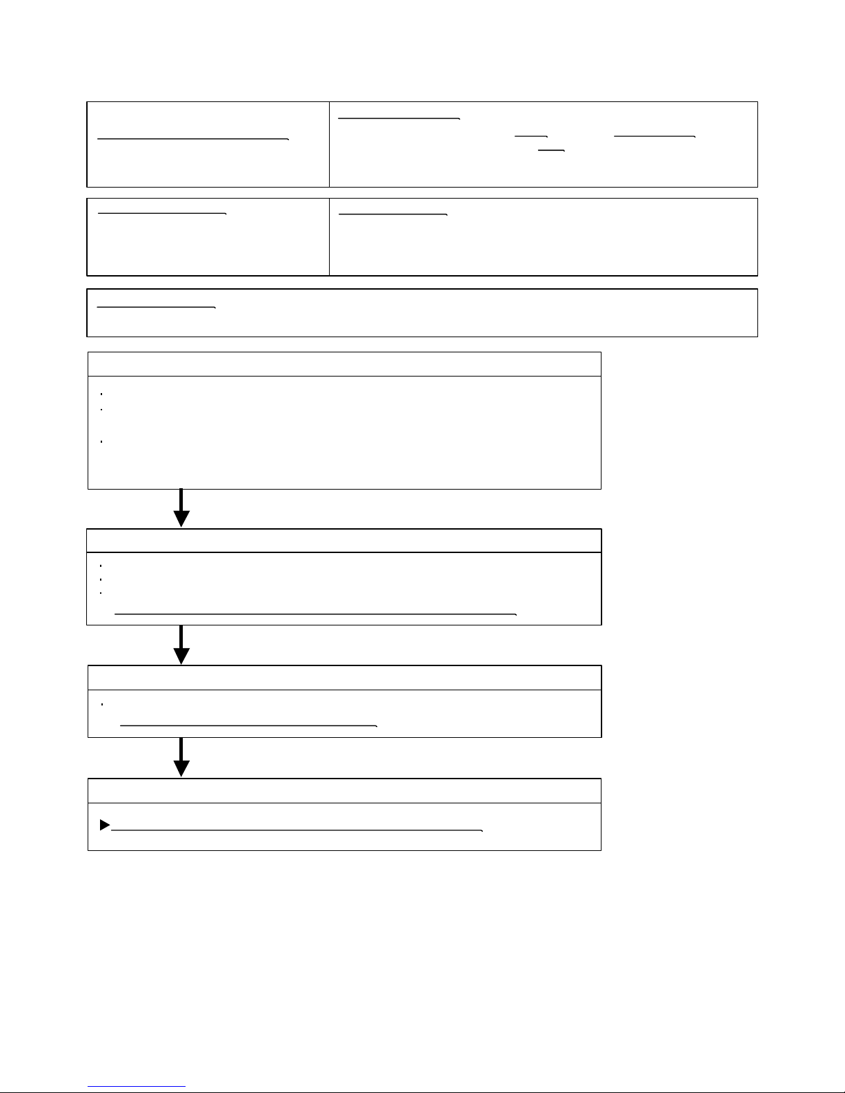
Trouble shooting 15
INDOOR UNIT
OUTDOOR UNIT Error Method:
Indicate or Display:
Outdoor Unit : No indication
Detective Actuators:
Detective details:
Forecast of Cause :
Check Point 3 : Check Active Filter Module
OKOK
OKOK
OKOK
Active Filter Module (AFM) error
Outdoor Unit Main PCB Circuit
Active Filter Module
1. External cause 2. Connector connection failure 3. Active Filter Module failure 4. Main PCB failure
Check Point 2 : Check connection of Connector
Check if connector is removed.
Check erroneous connection.
Check if cable is open.
>>Upon correcting the removed connector or mis-wiring, reset the power.
Check Active Filter Module. (PARTS INFORMATION 3)
>>If Active Filter Module is abnormal, replace it.
Check Point 4 : Replace Main PCB
If Check Point 1, 2 do not improve the symptom, change Main PCB.
Check Point 1 : Check external cause at Indoor and Outdoor (Voltage drop or Noise)
Instant drop : Check if there is a large load electric apparatus in the same circuit.
Momentary power failure : Check if there is a defective contact or leak current
in the power supply circuit.
Noise : Check if there is any equipment causing harmonic wave near electric line.
(Neon bulb or electric equipment that may cause harmonic wave)
Check the complete insulation of grounding.
07-16
When inverter input DC voltage is higher than 467V or
lower than 237V.
When a momentary power cut off occurred on low voltage.
Indoor Unit : Operation LED: Blink, Timer LED: 12 times blink,
Vertical swing LED: OFF
Page 63

Trouble shooting 16
OUTDOOR UNIT Error Method:
Detective Actuators:
Detective details:
Forecast of Cause :
Check Point 1 : Check connection of around the Compressor components
OKOK
Indicate or Display:Indicate or Display:
Outdoor Unit : LED 13 times blink
Check Point 2 : Replace Main PCB
Outdoor Unit Main PCB Circuit
Compressor rotor location cannot detect
(Permanent Stop)
1. Defective connection of electric components 2. Main PCB failure
If Check Point 1 do not improve the symptom, change Main PCB.
Check if connector is removed.
Check erroneous connection.
Check if cable is open.
>>Upon correcting the removed connector or mis-wiring, reset the power.
(Refer to PARTS INFORMATION 2)
For Compressor Terminal, Main PCB
While running the compressor, if the detected rotor location is out of
phase with actual rotor location more than 90 degrees,
the compressor stops.
After the compressor restarts, if the same operation is repeated
within 40sec, the compressor stops again.
If and repeats 5 times, the compressor stops permanently.
07-17
Indoor Unit : Operation LED: Blink, Timer LED: 13 times blink,
Vertical swing LED: OFF
Page 64

Trouble shooting 17
OUTDOOR UNIT Error Method:
Detective Actuators:
Detective details:
Forecast of Cause:
Check Point 2 : Check ambient temp. around motor
OK
OK
Indicate or Display:
Outdoor Unit : LED 15 (Fan motor 1) / 16(Fan motor 2) times blink
Outdoor Unit Fan Motor Error
Outdoor Unit Main PCB Circuit
Outdoor Fan Motor
1. Fan rotation failure 2. Motor protection by surrounding temperature rise 3. Main PCB failure
Check Point 1 : Check rotation of Fan
Rotate the fan by hand when operation is off.
(Check if fan is caught, dropped off or locked motor)
>>If Fan or Bearing is abnormal, replace it.
Check excessively high temperature around the motor.
(If there is any surrounding equipment that causes heat)
>>Upon the temperature coming down, restart operation.
When outdoor fan rotation speed is less than 100rpm in 20 seconds
after fan motor starts, fan motor stops.
After fan motor restarts, if the same operation within 60sec is repeated
3 times in a row, compressor and fan motor stops.
If and repeats 5 times in a row, compressor and fan motor stops
permanently.
07-18
Indoor Unit : Operation LED: Blink, Timer LED: 14 times blink,
Vertical swing LED: OFF
Check Point 3 : Check Output Voltage of Main PCB
Check outdoor unit circuit diagram and the voltage. (Measure at Main PCB side connector)
If the voltage is not correct, replace Main PCB.
AB*30/ 36LBAG AU*45LBAG
Read wire DC voltage
Red - Black
White - Black
300 400V
15 1.5V
〜
CN800
CN801
1
2
3
4
5
6
7
1
2
3
4
5
6
7
BLACK
WHITE
YELLOW
BROWN
RED
BLACK
WHITE
YELLOW
BROWN
RED
FM
FM
FAN MOTOR 1
FAN MOTOR 2
CN800
1
2
3
4
5
6
7
BLACK
WHITE
YELLOW
BROWN
RED
FM
FAN MOTOR 1
Page 65

Trouble shooting 18
OUTDOOR UNIT Error Method:
Indicate or Display:
Indoor Unit : No LED
Outdoor Unit : LED 8 Times Blink
Detective Actuators:
Detective details:
Forecast of Cause :
Check Point 2 :
Check Point 3 :
OKOK
OKOK
THERMISTOR
(DISCHARGE)
THERMISTOR
(PIPE)
THERMISTOR
(OUTDOOR)
THERMISTOR
(COMPRESSOR)
THERMISTOR
(HEAT SINK)
BROWN
BLACK
BLACK
BLUE
BROWN
CN21 CN22 CN23 CN26 CN25
1 2 1 2 1 2 1 2 1 2
30°C
6.109.7312.416.1Resistance Value (k )
20°C
7.67
15°C10°C5°C0°C
Temperature
1.79
1.25 0.89Resistance Value (k )
50°C
60°C 70°C
0.65
80°C
0.48
90°C
0.36
100°C
0.27
110°C
0.21
120°C
2.623.95
40°C
Temperature
Heat Sink Temperature Sensor Error
Outdoor Unit Main PCB Circuit
Heat Sink Temperature Thermistor
When Heat Sink Temperature Thermistor open or short-circuit is
detected at power ON or while running the compressor.
1. Connector connection failure 2.Thermistor failure 3. Main PCB failure
Check Point 1 : Check connection of Connector
Check if connector is removed.
Check erroneous connection.
Check if thermistor cable is open.
>>Upon correcting the removed connector or mis-wiring, reset the power.
Check Point 2 : Remove connector and check Thermistor resistance value
Thermistor Characteristics (Approx. value)
If Thermistor is either open or shorted, replace it and reset the power.
Check Point 3 : Check voltage of Main PCB (DC5.0V)
Make sure circuit diagram of outdoor unit and check terminal voltage at Thermistor (DC5.0V)
If the voltage does not appear, replace Main PCB.
07-19
Page 66
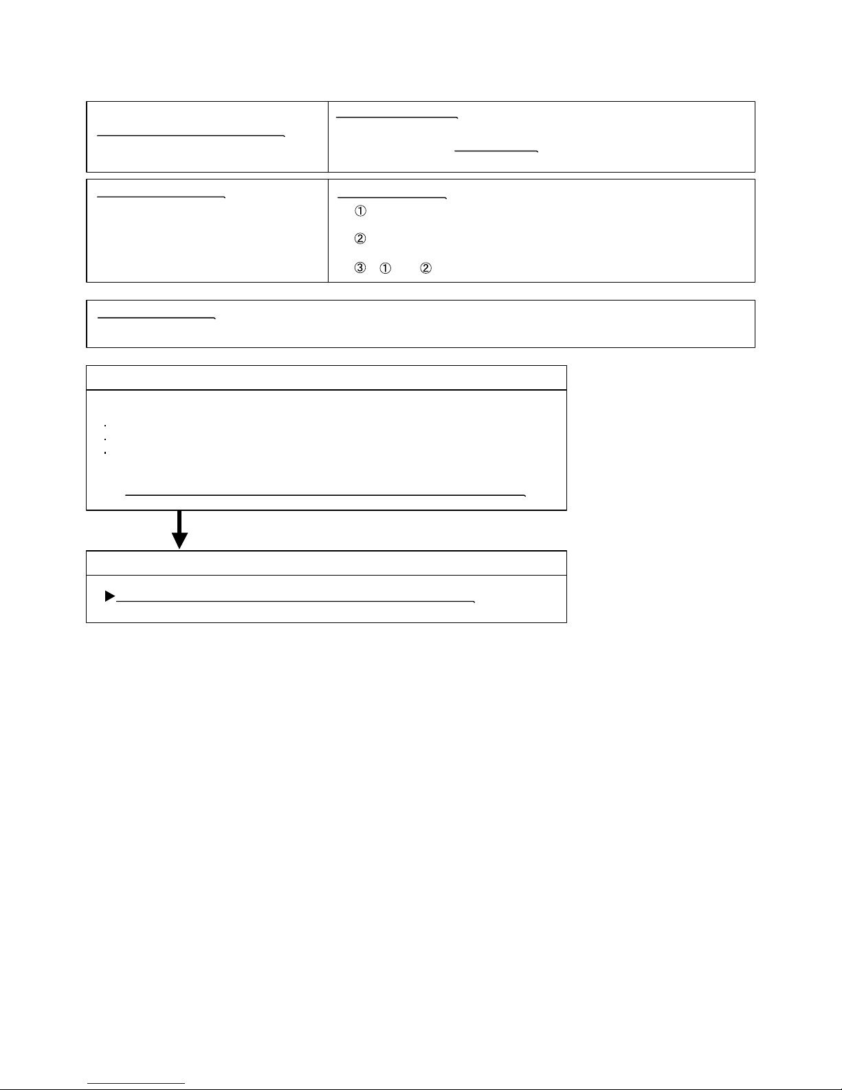
Trouble shooting 19
OUTDOOR UNIT Error Method:
Detective Actuators:
Detective details:
Forecast of Cause :
Indicate or Display:
Indoor Unit : No LED
Outdoor Unit : LED 14 Times Blink
Compressor Start-up error
(Permanent Stop)
On start-up the compressor, when detected rotor position is out of phase
with actual rotor position more than 90 degrees,the compressor stops.
After the compressor restarts, if the same operation is repeated
within 40sec, the compressor stops again.
If and repeats 5 times, the compressor stops permanently.
Outdoor Unit Main PCB Circuit
1. Defective connection of electric components 2. Main PCB failure
Check Point 1 : Check connection of around the Compressor components
OKOK
Check Point 2 : Replace Main PCB
If Check Point 1 do not improve the symptom, replace Main PCB.
Check if connector is removed.
Check erroneous connection.
Check if cable is open.
>>Upon correcting the removed connector or mis-wiring, reset the power.
(Refer to PARTS INFORMATION 2)
For Compressor Terminal, Main PCB
07-20
Page 67

Trouble shooting 20
Forecast of Cause:
YESYES
NO
OKOK
OKOK
OKOK
Indoor Unit - No Power
1. Power Supply failure 2. External cause
3. Electrical Components defective
Check Point 1 : Check Installation Condition
Isn’t the breaker down?
Check loose or removed connection cable.
>>If abnormal condition is found, correct it by referring
to Installation Manual or Data & Technical Manual.
Check Point 2 : Check external cause at Indoor and Outdoor (Voltage drop or Noise)
Instant drop ----- Check if there is a large load electric apparatus in the same circuit.
Momentary power failure ----- Check if there is a defective contact or leak current in
the power supply circuit.
Noise ----- Check if there is any equipment causing harmonic wave near electric line.
(Neon bulb or electric equipment that may cause harmonic wave)
Check the complete insulation of grounding.
Check Point 3 : Check Electrical Components
Check Voltage of power supply.
>> Check AC198 - 264V appears at Indoor Unit Terminal 1 - 2 (Power Supply).
Check Fuse (F101) in Filter PCB.
>> If Fuse is open, check if the wiring between Terminal and Filter PCB
is loose, and replace Fuse.
Check Varistor (VA101, VA102) in Filter PCB.
>> If Varistor is defective, there is a possibility of an abnormal power supply.
Check the correct power supply and replace Varistor.
If the symptom does not change by above Check3, replace Filter PCB.
07-21
7-3 TROUBLE SHOOTING WITH NO ERROR CODE
Page 68

Trouble shooting 21
Forecast of Cause:
Check Point 3 : Check Electrical Components
OKOK
OKOK
YESYES
OK
NO
Check Point 1 : Check Installation Condition
Outdoor Unit - No Power
1. Power Supply failure 2. External cause
3. Electrical Components defective
Isn’t the breaker down?
Check loose or removed connection cable.
>>If abnormal condition is found, correct it by referring
to Installation Manual or Data & Technical Manual.
Check Point 2 : Check external cause at Indoor and Outdoor (Voltage drop or Noise)
Instant drop ----- Check if there is a large load electric apparatus in the same circuit.
Momentary power failure ----- Check if there is a defective contact or leak current in the power supply circuit.
Noise ----- Check if there is any equipment causing harmonic wave near electric line.
(Neon bulb or electric equipment that may cause harmonic wave)
Check the complete insulation of grounding.
Check the voltage of power supply.
>> Check if AC198 - 264V appears at Outdoor Unit Terminal L - N.
YESYES
Check Fuse (F2, F4) in Main PCB.
>> If Fuse is open, check loose terminal or removed connector (CN1) , and replace Fuse.
Check Varistor in Main PCB (VA103).
>> If Varistor is defective, there is a possibility of an abnormal power supply.
Check the correct power supply and replace Varistor.
Upon checking the normal power supply, replace Varistor.
If the symptom does not change by above Check 3, replace Main PCB.
Check Active Filter Module. (PARTS INFORMATION 3)
>>If Active Filter Module is abnormal, replace it.
07-22
Page 69

Trouble shooting 22
Forecast of Cause:
Check Point 2 : Check external cause at Indoor and Outdoor (Voltage drop or Noise)
Check Point 1 : Check indoor and outdoor installation condition
Check Point 3 : Check Electrical Components at Indoor and Outdoor
OK
OK
OKOK
No Operation (Power is ON)
1. Setting/ Connection failure 2. External cause
3. Electrical Component defective
Indoor Unit - Check incorrect wiring between Indoor Unit - Remote Control, or terminals between Indoor Units.
Or, check if there is an open cable connection.
Are these Indoor Unit, Outdoor Unit, and Remote Control suitable model numbers to connect?
>> If there is some abnormal condition, correct it by referring to Installation manual and
Data & Technical Manual.
Turn off Power and check/ correct followings.
Is there loose or removed communication line of Indoor Unit and Outdoor Unit?
Instant drop ----- Check if there is a large load electric apparatus in the same circuit.
Momentary power failure ----- Check if there is a defective contact or leak current in the power supply circuit.
Noise ----- Check if there is any equipment causing harmonic wave near electric line.
(Neon bulb or electric equipment that may cause harmonic wave)
Check the complete insulation of grounding.
Check Voltage at CN17 of Controller PCB. (Power supply to Remote Control)
>> If it is DC12V, Remote Control is failure. (Controller PCB is normal) >> Replace Remote Control
>> If it is DC 0V, Controller PCB is failure. (Check Remote Control once again) >> Replace Controller PCB
>> If the symptom does not change by above Check 1, 2, 3, replace Main PCB of Outdoor unit.
07-23
Page 70

Attention
Trouble shooting 23
Forecast of Cause:
Check Point 2 : Check Outdoor Unit Operation
Check Point 1 : Check Indoor Unit
Check Point 3 : Check Site Condition
Check Point 5 : Check Refrigeration Cycle
Check Point 4 :
Check Indoor/ Outdoor Installation Condition
Pipe (In) Pipe (Out)
Pipe (In) Pipe (Out)
OKOK
OKOK
OKOK
OKOK
MPa MPa
No Cooling / No Heating
1. Indoor Unit error 2. Outdoor Unit error
3. Effect by Surrounding environment
4. Connection Pipe / Connection Wire failure 5. Refrigeration cycle failure
Does Indoor Unit FAN run on HIGH FAN?
Is Air Filter dirty?
Is Heat Exchanger clogged?
Check if Energy save function is operated.
Check if Outdoor Unit is operating
(If not, refer to Trouble shooting 22)
Check any objects that obstruct the air flow route.
Check clogged Heat Exchanger.
Is the Valve open?
Is capacity of Indoor Unit fitted to Room size?
Any windows open? Or direct sunlight ?
Check connection pipe
(specified pipe length & Pipe diameter?)
Check any loose or removed communication line.
>> If there is an abnormal condition, correct it by
referring to Installation Manual or Data & Technical
Manual.
Check if Strainer is clogged (Refer to the figure at right).
Measure Gas Pressure and if there is a leakage, correct it.
>> When recharging the refrigerant, make sure to perform
vacuuming, and recharge the specified amount.
Check EEV (PARTS INFORMATION 4)
Check Compressor (PARTS INFORMATION 1,2)
Strainer normally does not have temperature difference
between inlet and outlet as shown in , but if there is a
difference like shown in , there is a possibility of inside
clogged. In this case, replace Strainer.
07-24
Page 71

Trouble shooting 24
Forecast of Cause :
Trouble shooting 25
Forecast of Cause:
OK
OK
OK
OK
OKOK
OKOK
OKOK
MPa MPa
Abnormal Noise
1. Abnormal installation (Indoor/ Outdoor) 2. Fan failure(Indoor/ Outdoor)
3. Compressor failure (Outdoor)
Diagnosis method when Abnormal Noise is occurred
Abnormal noise is coming from Indoor Unit.
(Check and correct followings)
Abnormal noise is coming from Outdoor Unit.
(Check and correct followings)
Is Fan broken or deformed?
Is the screw of Fan loose?
Is there any object which obstruct the Fan rotation?
Is Main Unit installed in stable condition?
Is the installation of Air suction grille and
front panel normal?
Is Fan broken or deformed?
Is the screw of Fan loose?
Is there any object which obstruct the Fan rotation?
Is Main Unit installed in stable condition?
Is Fan Guard installed normally?
Check if vibration noise by loose bolt or contact noise
of piping is happening.
Is Compressor locked?
>> Check Compressor (PARTS INFORMATION 1,2)
Water Leaking
1. Erroneous installation 2. Drain hose failure
Diagnosis method when water is spitting out.
Is the filter clogged?
Check Gas Pressure and correct it
if there was a gas leak.
Diagnosis method when water leak occurs
Is Drain Hose connection loose?
Is there a trap in Drain Hose?
Is Drain Hose clogged?
Is Main Unit installed in stable condition?
Is Main Unit broken or deformed at the time of
transportation or maintenance?
Is Fan rotating?
>> Check Fan Motor (PARTS INFORMATION 5)
07-25
Page 72

SERVICE PARTS INFORMATION 1
Compressor
Diagnosis method of Compressor ( If Outdoor Unit LED displays Error, refer to Trouble shooting )
Does not start up
Is there open or loose connection
cable?
Check Filter PCB, Main PCB,
connection of Compressor,and winding
resistance. (Refer to the next page).
Check Filter PCB, Main PCB,
connection of Compressor,and winding
resistance. (Refer to the next page).
>> If there is no failure, the defect of
Compressor is considered (Locked
compressor due to clogged dirt or
less oil)
Replace Compressor
Replace Compressor
Replace Compressor
Stops soon after starting up
Is there open or loose connection
cable?
Is Gas Pipe Valve open?
(Low Pressure is too low)
Check if Refrigerant is leaking.
(Recharge Refrigerant)
Check if Strainer is clogged.
(PARTS INFORMATION 4)
>> If there is no failure, the defect of Compressor can be
considered. (Compression part broken or valve defective.)
Abnormal noise
Defective Compressor
can be considered.
(due to inside dirt clogging
or broken component)
Check if vibration noise by
loose bolt or contact noise
of piping is happening.
07-26
7-4 SERVICE PARTS INFORMATION
MPa MPa
Page 73

SERVICE PARTS INFORMATION 2
Check Point 1 : Check Connection
UU(RED)(RED)
V V (WHITE)(WHITE)WW
(BLACK)(BLACK)
Terminal cover opened
MAIN PCB
Check Point 2 : Check Winding Resistance
Check Point 3 : Replace Main PCB
U
V
W
W304
(TM304)
W305
(TM305)
W303
(TM303)
RED
WHITE
BLACK
Compressor
Inverter Compressor
Check terminal connection of Compressor
(loose or incorrect wiring)
Check connection of Main PCB
(Loose or incorrect wiring)
Check winding resistance of each terminal
If the resistance value is 0 or infinite, replace Compressor.
If the symptom does not change with above Check 1, 2, replace Main PCB.
Resistance Value :
0.88 (For AB*30/ 36LBAG)
0.188 (For AB*45LBAG)
at 20°C
07-27
Page 74

SERVICE PARTS INFORMATION 3
Check Point 1 : Check Open or Short-circuit and Diode (D1)
Check Point 2 : Check the Output DC voltage (between P and N1)
L2L1
P
N2
N1
Power factor control
D1
(+)
( )
Io
Check the Output DC voltage (between P and N1) of compressor stopping and operating.
If it is abnormal,replace ACTIVE FILTER MODULE
Active Filter Module
Remove connector, check the open or short-circuit and the diode in the module
>> If the output voltage of compressor operating is less than the output voltage of compressor stopping,
Active Filter Module is detective. >> Replace Active Filter Module
07-28
Terminal
Resistance value
L2
L1
L1,L2
P
P
Control Box
N1
N1
(+)
(+)
( )
( )
Tester(+) Tester(-)
Check the open or short-circuit
L2
P
P
N2
L2
L2
Check the diode
0
360k
720k
1.65M /
20%
+
-
360k
20%
+
-
20%
+
-
(Ref. value 1)
1.14M
(Ref. value 2)
1.01M /
(Ref. value 1)
761k
(Ref. value 2)
Terminal
Resistance value
Tester(+) Tester(-)
1.32M /
(Ref. value 1)
663k
(Ref. value 2)
1.01M /
(Ref. value 1)
762k
(Ref. value 2)
Ref. value 1
Specifications for Multimeter
Manufacturer : FLUKE
Model name : FLUKE11
Power source : DC9V.
Ref. value 2
Specifications for Multimeter
Manufacturer : Sanwa
Model name : PM3
Power source : DC3V.
Page 75

SERVICE PARTS INFORMATION 4
Check Point 2 : Check Coil of EEV
Yellow - Brown
Orange - Red
Blue - Brown
White - Red
Read wire
46 4
Resistance value
Check Point 1 : Check Connections
Check Point 5 : Check Opening and Closing Operation of Valve
Check Point 3 : Check Voltage from Main PCB.
Check Point 4 : Check Noise at start up
Pipe (In)
Pipe (Out)
Hi TEMP.
Pipe (In)
Hi TEMP.
Normal TEMP.
CLOSE
Example : Hot Gas
OPEN
Example : Hot Gas
Pipe (Out)
Hi TEMP.
Pipe (In) Pipe (Out)
Pipe (In) Pipe (Out)
Check Point 6 : Check Strainer
DC
CN27
EXPANSION
VALVE COIL
EV
RED
BROWN
BLUE
ORANGE
YELLOW
WHITE
1
2
3
4
5
6
at 20°C
Outdoor unit Electronic Expansion Valve
( EEV )
Check connection of connector (CN27)
( Loose connector or open cable )
Remove connector, check each winding
resistance of Coil.
If Resistance value is abnormal, replace EEV.
Remove Connector and check Voltage (DC12V)
If it does not appear, replace Main PCB.
Turn on Power and check operation noise.
If an abnormal noise does not show, replace Main PCB.
When Valve is closed,
it has a temp. difference between Inlet and Outlet.
If it is open,
it has no temp. difference between Inlet and Outlet.
Strainer normally does not have temperature difference between inlet and outlet as shown in ,
but if there is a difference as shown in , there is a possibility of inside clogged. In this case, replace Strainer.
07-29
Page 76

SERVICE PARTS INFORMATION 5
Check Point :
22.8 10%
31.9 10%
Resistance value
(AC)
Thermal protector
115 125°C
Pr
1
1 3
2
3
The connector
inserting numbers
2 3
at 20°C
Indoor Unit Fan Motor
Check each winding resistance of the motor
If Resistance value is abnormal, replace motor.
07-30
Page 77

8 . APPENDING DATA
R410A
INVERTER
Large Ceiling type
Page 78

08-01
MODEL : AB*30/ 36LBAG / AO*30/ 36LMBWL
MODEL : AB*45LBAG / AO*45LJBYL
COOLING
HEATING
8-1. CAPACITY TABLE
8. APPENDING DATA
AFR: Air flow rate (m3/min)
TC : Total capacity (kW)
SHC: Sensible Heat capacity (kW)
PI : Power Input (kW)
AFR: Air flow rate (m3/min)
TC : Total capacity (kW)
SHC: Sensible Heat capacity (kW)
PI : Power Input (kW)
AFR 27.7
(°CDB) TC SHC PI TC SHC PI TC SHC PI TC SHC PI T C SHC PI TC SHC PI TC SHC PI TC SHC PI
-10 6.53 5.57 1.51 6.95 5.42 1.57 7.09 5.88 1.59 7.35 6.27 1.62 7.48 6.21 1.64 7. 73 6.07 1.66 7.84 6.00 1.67 7.95 6.43 1.68
0 7.19 5.97 1.28 7.82 5.93 1.31 8.02 6.39 1.32 8.44 6.82 1.34 8.65 6.78 1.34 9.08 6.68 1.36 9.28 6.63 1.36 9.49 7.07 1.37
10 6.43 5.52 1.56 7.01 5.45 1.60 7.19 5.93 1.61 7.56 6.36 1.63 7.75 6.31 1.64 8.11 6.22 1.66 8.29 6.16 1.67 8.46 6.60 1.67
20 8.13 6.39 1.88 9.04 6.41 1.89 9.36 6.92 1.88 10.01 7.41 1.88 10.35 7.40 1.88 11.04 7.36 1.87 11.39 7.33 1.86 11.73 7.79 1.86
30 7.02 5.82 2.28 7.87 5.85 2.30 8.15 6.36 2.31 8.74 6.86 2.32 9.05 6.85 2.32 9.67 6.81 2.32 9.99 6.79 2.32 10.29 7.26 2.31
35 7.72 6.18 3.36 8.68 6.24 3.44 9.01 6.76 3.46 9.65 7.25 3.43 10.00 7.25 3.45 10.73 7.23 3.48 11.03 7.19 3.43 11.40 7.66 3.44
40 5.97 5.28 3.30 6.74 5.33 3.30 7.01 5.89 3.30 7.56 6.36 3.30 7.85 6.35 3.30 8.35 6.31 3.30 8.65 6.29 3.30 8.94 6.77 3.30
43 5.41 5.01 3.30 6.14 5.05 3.30 6.39 5.58 3.30 6.90 6.09 3.30 7.17 6.08 3.30 7.64 6.04 3.30 7.92 6.03 3.30 8.19 6.51 3.30
15 °CWB
16 °CWB
18 °CWB
19 °CWB
26 °CDB
27 °CDB
29 °CDB
30 °CDB
32 °CDB
21 °CWB
18 °CDB
12 °CWB
21 °CDB
22 °CWB
23 °CWB
Outdoor temperature
23 °CDB
Indoor temperature
AFR 27.7
(°CDB)
(°CWB)
TC PI TC PI TC PI TC PI TC PI TC PI TC PI
-10 -11 5.83 2.44 5.72 2.49 5.58 2.54 5.35 2.64 5.20 2.70 5.05 2.76 4.81 2.85
-4 -6 6.74 2.57 6.63 2.63 6.51 2.68 6.27 2.78 6.11 2.84 5.94 2.91 5.69 3.01
1 -1 7.77 2.69 7.66 2.75 7.53 2.81 7.26 2.91 7.08 2.99 6.89 3.06 6.61 3.17
7 6 11.55 3.35 11.39 3.43 11.20 3.50 10.79 3.64 10.52 3.73 10.24 3.83 9.79 3.97
12 10 12.60 3.45 12.41 3.53 12.21 3.61 11.77 3.76 11.46 3.85 11.13 3.95 10.63 4.10
18 13 13.08 3.40 12.76 3.42 12.44 3.43 11.83 3.39 11.42 3.41 11.01 3.43 10.35 3.42
20 15 11.90 2.94 11.66 2.96 11.40 2.97 10.93 2.96 10.63 2.96 10.20 2.92 9.56 2.91
24 17 12.38 2.98 12.02 2.94 11.75 2.95 11.26 2.94 10.96 2.94 10.62 2.95 9.45 2.94
30 °CDB
Outdoor temperature
Indoor temperature
16 °CDB
18 °CDB
20 °CDB
23 °CDB
25 °CDB
27 °CDB
COOLING
HEATING
AFR 33.3
(°CDB)
(°CWB)
TC PI TC PI TC PI TC PI TC PI TC PI TC PI
-15 -16 8.53 3.78 8.35 3.84 8.24 4.14 7.86 4.14 7.75 4.60 7.45 4.60 7.07 4.60
-10 -11 10.50 4.20 10.28 4.27 10.03 4.34 9.68 4.46 9.55 4.60 9.17 4.60 8.71 4.60
-4 -6 12.45 4.38 12.18 4.47 11.91 4.54 11.42 4.60 11.06 4.60 10.71 4.60 10.12 4.60
1 -1 14.35 4.60 13.97 4.60 13.59 4.60 12.94 4.60 12.45 4.60 12.04 4.60 11.36 4.60
7 6 16.74 4.60 16.24 4.60 16.00 4.60 15.12 4.60 14.50 4.60 13.85 4.60 12.99 4.60
12 10 17.66 4.60 17.13 4.60 16.59 4.60 15.89 4.60 15.22 4.60 14.68 4.60 13.73 4.60
18 13 18.47 4.60 18.08 4.60 17.52 4.60 16.70 4.60 16.15 4.60 15.52 4.60 14.48 4.60
20 15 18.20 4.60 17.71 4.60 17.33 4.60 16.53 4.60 15.82 4.60 15.28 4.60 14.32 4.60
24 17 17.50 4.60 17.01 4.60 16.62 4.60 15.82 4.60 15.11 4.60 14.61 4.60 13.62 4.60
25 °CDB
27 °CDB
30 °CDB
Outdoor temperature
Indoor temperature
16 °CDB
18 °CDB
20 °CDB
23 °CDB
AFR 33.3
(°CDB) TC SHC PI TC SHC PI TC SHC PI TC SHC PI TC SHC PI TC SHC PI TC SHC PI TC SHC PI
-15 10.06 8.70 2.04 10.59 9.45 2.06 11.13 10.24 2.08 12.07 11.58 2.11 12.55 11.61 2.13 13.50 11.65 2.17 13.99 11.67 2.19 14.49 12.59 2.20
-10 12.00 9.50 2.43 12.64 10.33 2.45 12.97 11.25 2.46 13.63 12.06 2.49 13.95 11.97 2.51 14.57 11.75 2.53 14.86 11.61 2.54 15.12 12.39 2.55
0 11.01 8. 66 3.02 11.59 9.41 3.05 11.86 10.31 3.07 12.42 11.10 3.11 12.69 11.00 3.13 13.23 10.81 3.15 13.48 10.71 3.16 13.73 11.53 3.17
10 10.47 8.42 3.33 11.02 9.16 3.36 11.30 10.06 3.38 11.85 10.87 3.42 12.13 10.79 3.43 12.66 10.60 3.46 12.94 10.52 3.48 13.19 11.35 3.49
20 12.61 9.37 3.51 13.27 10.18 3.53 13.69 11.13 3.53 14.54 12.03 3.52 14.99 11.99 3. 52 15.91 11.94 3.50 16.33 11.89 3.48 16.78 12.76 3.47
30 11.13 8.71 4.23 11.71 9.47 4.24 12.12 10.42 4.25 12.95 11.32 4.26 13.37 11.28 4.27 14.23 11.18 4.27 14.66 11.13 4.27 15.06 11.99 4.27
35 11.10 8.70 5.13 11.68 9.46 5.13 12.09 10.41 5.16 12.86 11.29 5.13 14.00 11.25 5.15 14.02 11.40 5.18 14.43 11.04 5.13 14.82 11.91 5.15
40 9.61 7.92 5.00 10.12 8.60 5.00 10.37 9.48 5.00 10.97 10.31 5.00 11.34 10.32 5.00 12.55 10.23 5.00 12.29 10.22 5.00 12.63 11.08 5.00
43 8.82 7.57 5.00 9.28 8.23 5.00 9.62 9.16 5.00 10.26 10.01 5.00 10.63 9.98 5.00 11.18 9.85 5.00 11.51 9.80 5.00 11.84 10.64 5.00
19 °CWB
30 °CDB
Outdoor temperature
26 °CDB
18 °CWB
21 °CDB
23 °CDB
15 °CWB
16 °CWB
18 °CDB
12 °CWB
Indoor temperature
27 °CDB
29 °CDB
32 °CDB
21 °CWB
22 °CWB
23 °CWB
Page 79

08-02
MODEL : AB*30/ 36LBAG / AO*30/ 36LMBWL
Indoor temperature
Indoor humidity
Outdoor temperature
Cooling
Dry
18 to 32°C
About 80% or less
-10 to 43°C
Heating
16 to 30°C
-
-10 to 24°C
Operation Range
Mode
MODEL : AB*45LBAG / AO*45LJBYL
Indoor temperature
Indoor humidity
Outdoor temperature
Cooling
Dry
18 to 32°C
About 80% or less
-15 to 43°C
Heating
16 to 30°C
-
-15 to 24°C
Operation Range
Mode
8-2. OPERATION RANGE
Page 80

08-03
8-3. ELECTRIC CHARACTERISTICS
Indoor unit
Outdoor unit
Voltage V
Frequency Hz
Cooling Heating Cooling Heating
Current A 13.1 12.7 18.0 14.2
Input kW 3.00 2.90 4.12 3.26
Max Operating Current A 15.2 15.3 18.3 18.1
Starting Current A
Main Fuse (Circuit breaker) Current A
Power Cable
mm
2
*2)Limited wiring length m
Input kW
Full Load Amp. A
Input kW
Full Load Amp. A
Model Name
AB 30LBAG AB 36LBAG
AO 30LMBWL AO 36LMBWL
Power Supply
230
230
50
50
Rated Value
Mode
*1) Wiring Spec
30
23
10
3.5
3.5
Indoor Fan Motor
0.22
0.22
1.0
1.0
0.6
0.6
10
Outdoor Fan Motor
0.13
0.131930
Indoor unit
Outdoor unit
Voltage V
Frequency Hz
Cooling Heating
Current A 19.5 18.5
Input kW 4.45 4.25
Max Operating Current A 22.6 20.0
Starting Current A
Main Fuse (Circuit breaker)
Current
A
Power Cable
mm
2
*2)Limited wiring length m
Input kW
Full Load Amp. A
Input kW
Full Load Amp. A
*1) Wiring Spec : Selected Sample (Selected based on Japan Electrotechnical Standard
and Codes Committee E0005)
*2) Limited Wiring length : This is the wiring length in case voltage descent is less than 2%.
When the wiring length becomes long, please select the wiring
of a more larger diameter.
Model Name
Outdoor Fan Motor
0.067 x 2
0.34 x 2
Indoor Fan Motor
0.23
1.35
6.0
Rated Value
Mode
*1) Wiring Spec
30
27
15
Power Supply
230
50
AB 45LBAG
AO 45LJBYL
Page 81

08-04
OUTDOOR UNIT
PROTECTION FORM AO*30LMBWL AO*36LMBWL
FUSE (SIDE OF POWER SUPPLY TERMINAL) - 25A 250V 25A 250V
FUSE (SIDE OF INDOOR UNIT) - 10A 250V 10A 250V
- 3.15A 250V 3.15A 250V
- 5A 250V 5A 250V
FAN MOTOR PROTECTOR THERMAL PROTECTOR 150±5°C OFF 150±5°C OFF
HIGH PRESSURE PROTECTION PRESSURE SWITCH
OFF:4.2±0.1MPa
ON:3.2±0.15MPa
OFF:4.2±0.1MPa
ON:3.2±0.15MPa
DISCHARGE THERMISTOR THERMAL PROTECTOR
OFF:120±5°C
ON:80±5°C
OFF:120±5°C
ON:80±5°C
COMPRESSOR THERMISTOR THERMAL PROTECTOR
OFF:130±5°C
ON:80±5°C
OFF:130±5°C
ON:80±5°C
FUSE ON MAIN PCB
INDOOR UNIT
PROTECTION FORM AB*30LBAG AB*36LBAG
PCB FUSE -
FAN MOTOR PROTECTION
PROTECTION FORM AO*45LJBYL
FUSE
(SIDE OF INDOOR UNIT TERMINAL)
- 10A 250V
- 3.15A 250V
3.15A 250V
- 5A 250V
FAN MOTOR PROTECTOR THERMAL PROTECTOR 150±5°C OFF
120±5°C OFF
HIGH PRESSURE PROTECTION PRESSURE SWITCH
OFF:4.2±0.1MPa
ON:3.2±0.15MPa
DISCHARGE THERMISTOR THERMAL PROTECTOR
OFF:120±5°C
ON:80±5°C
COMPRESSOR THERMISTOR THERMAL PROTECTOR
THERMAL PROTECTOR
PROTECTION FORM AB*45LBAG
PCB FUSE -
FAN MOTOR PROTECTION
3.15A 250V
120±5°C OFF
THERMAL PROTECTOR
OFF:130±5°C
ON:80±5°C
FUSE ON MAIN PCB
8-4. SAFETY DEVICE
Page 82

08-05
Indoor unit control circuit board
SWITCH POSITION
Auto restart validity / invalidity
Room temperature correct coefficient
Room temperature correct coefficient
Forbidden
Remote control unit signal code
INDOOR UNIT
DIP SW
3
JM3
Jumper Wire
JM1
JM2
SW1
1
2
SW1
SW1
ON OFF
3
2
1
JM1
JM2
JM3
8-5. FUNCTION SETTING
8-5-1 INDOOR UNIT
Page 83

08-06
DIP SWITCH SETTING
JUMPER WIRE SETTING
Auto restart function can be selected by turning this switch ON/OFF.
AUTO RESTART SETTING
SW1-1. Auto restart setting
( Factory setting)
Decide the heating temperature correct coefficient vale of heating.
TEMPERATURE CORRECTION
SW1-2, 1-3. Room temperature correct coefficient of heating.
( Factory setting)
SW 1-1
SW state
OFF
Invalidity
ON
Validity
0 deg
0 deg
0 deg
cooling
-2 deg
SW 1-2
SW 1-3
0 deg
heating
dry
-2 deg
-2 degONONONOFF
OFF
+2 deg
-2 deg
OFF
SW state
-2 deg
OFF
ON
0 deg
+4 deg
( Factory setting)
Remote control unit
signal code
JM 1, 2, 3 setting forbidden
Jumper wire
JM2 JM3
connect connect
A
connect Disconnect
B
Disconnect connect
C
Disconnect Disconnect
D
Page 84
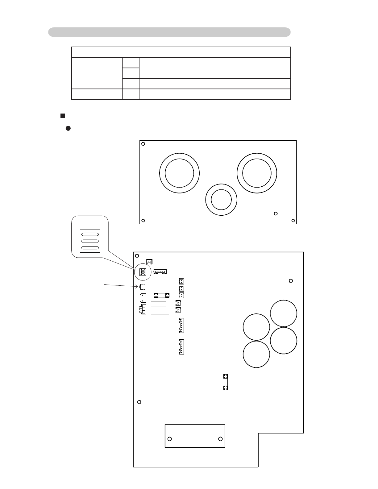
08-07
Pump down switch
Change current capacity
No use (OFF)
1
OUTDOOR UNIT
2
3
DIP SW 1
PUSH SW
PUSH SW
1
DIP SW 1
OFF ON
2
3
Outdoor unit control circuit board
SWITCH POSITION
8-5-2 OUTDOOR UNIT ( AO*30/ 36LMBWL )
Page 85

08-08
DIP SWITCH SETTING
Current capacity setting
*1=36000BTU model's factory setting (AO*36LMBWL)
*2=30000BTU model's factory setting (AO*30LMBWL)
13.5A
12.0A
DIP-SW1
CURRENT
(MAX.)
18.0A *1
15.0A *2
OFF
OFF
OFFONON
OFF
ON
OFF
1
OFF
ON23
OFF
OFF
PUSH SWITCH SETTING
Press the push-button switch, and "PUMP DOWN OPERATION" is starting.
SW2 setting
Page 86

08-09
Pump down switch
Change current capacity
No use (OFF)
1
OUTDOOR UNIT
2
3
DIP SW 1
PUSH SW
PUSH SW
1
DIP SW 1
OFF ON
2
3
Outdoor unit control circuit board
SWITCH POSITION
8-5-3 OUTDOOR UNIT ( AO*45LJBYL )
Page 87

08-10
DIP SWITCH SETTING
Current capacity setting
*1=54000BTU model's factory setting
*2=45000BTU model's factory setting (AO*45LJBYL)
18.0A
15.5A
DIP-SW1
CURRENT
(MAX.)
23.5A *1
20.0A *2
OFF
OFF
OFFONON
OFF
ON
OFF
1
OFF
ON23
OFF
OFF
PUSH SWITCH SETTING
Press the push-button switch, and "PUMP DOWN OPERATION" is starting.
SW2 setting
Page 88

9 . INSTALLATION MANUAL
R410A
INVERTER
Large Ceiling type
Page 89

3
2
1
SPLIT TYPE AIR CONDITIONER
INSTALLATION INSTRUCTION
SHEET
(PART NO. 9366160052)
For authorized service personnel only.
WARNING
This mark indicates procedures which, if improperly performed, might lead to the death or serious injury of
the user.
CAUTION
This mark indicates procedures which, if improperly performed, might possibly result in personal harm to
the user, or damage to property.
This air conditioner uses new refrigerant HFC (R410A).
The basic installation work procedures are the same as conventional refrigerant models.
However, pay careful attention to the following points:
1 Since the working pressure is 1.6 times higher than that of conventional refrigerant models, some of the piping and
installation and service tools are special. (See the table below.)
Especially, when replacing a conventional refrigerant model with a new refrigerant R410A model, always replace the
conventional piping and flare nuts with the R410A piping and flare nuts.
2 Models that use refrigerant R410A have a different charging port thread diameter to prevent erroneous charging with
conventional refrigerant and for safety. Therefore, check beforehand. [The charging port thread diameter for R410A is
1/2 UNF 20 threads per inch.]
3 Be more careful that foreign matter (oil, water, etc.) does not enter the piping than with refrigerant models. Also, when
storing the piping, securely seal the openings by pinching, taping, etc.
4 When charging the refrigerant, take into account the slight change in the composition of the gas and liquid phases, and
always charge from the liquid phase side whose composition is stable.
5 When moving, if the compressor stops during pump down, close the valve immediately.
Special tools for R410A
Copper pipes
- Continued on back -
Refrigerant
R410A
Contents of change
Pressure is high and cannot be measured with a conventional gauge. To prevent erroneous mixing of other
refrigerants, the diameter of each port has been changed.
It is recommended the gauge with seals –0.1 to 5.3 MPa (–76 cmHg to 53 kgf/cm
2
) for high pressure. –0.1 to
3.8 MPa (–76 cmHg to 38 kgf/cm
2
) for low pressure.
To increase pressure resistance, the hose material and base size were changed.
A conventional vacuum pump can be used by installing a vacuum pump adapter.
Special gas leakage detector for HFC refrigerant R410A.
Tool name
Gauge manifold
Charge hose
Vacuum pump
Gas leakage detector
Ceiling Suspension Type
CONNECTION PIPE REQUIREMENT
ELECTRICAL REQUIREMENT
••
••
• Electric wire size:
2. BENDING PIPES
CAUTION
1 To prevent breaking of the pipe, avoid sharp bends.
Bend the pipe with a radius of curvature of 150 mm or
over.
2 If the pipe is bent repeatedly at the same place, it will
break.
6.35 mm (1/4 in.)
9.52 mm (3/8 in.)
12.70 mm (1/2 in.)
15.88 mm (5/8 in.)
19.05 mm (3/4 in.)
0.80 mm
0.80 mm
0.80 mm
1.00 mm
1.20 mm
Pipe outside diameter
Thickness
Thicknesses of Annealed Copper Pipes (R410A)
SELECTING THE MOUNTING POSITION
Decide the mounting position with the customer as follows:
1
INSTALLATION PROCEDURE
CAUTION
Install heat insulation around both the gas and liquid pipes. Failure to do so may cause water leaks.
Use heat insulation with heat resistance above 120 °C. (Reverse cycle model only)
In addition, if the humidity level at the installation location of the refrigerant piping is expected to exceed 70%, install heat
insulation around the refrigerant piping. If the expected humidity level is 70-80%, use heat insulation that is 15 mm or thicker
and if the expected humidity exceeds 80%, use heat insulation that is 20 mm or thicker.
If heat insulation is used that is not as thick as specified, condensation may form on the surface of the insulation.
In addition, use heat insulation with heat conductivity of 0.045 W/(m·K) or less (at 20 °C).
••
••
• Use pipe with water-resistant heat insulation.
INDOOR UNIT
(1) Install the indoor unit level on a strong wall which is not subject to
vibration.
(2) The inlet and outlet ports should not be obstructed : the air should be
able to blow all over the room.
(3) Do not install the unit where it will be exposed to direct sunlight.
(4) Install the unit where connection to the outdoor unit is easy.
(5) Install the unit where the drain pipe can be easily installed.
(6) Take servicing, etc., into consideration and leave the spaces shown
in the figure. Also install the unit where the filter can be removed.
WARNING
Select installation locations that can properly support the weight of the indoor and outdoor units. Install the units securely so
that they do not topple or fall.
CAUTION
1 Do not install where there is the danger of combustible gas leakage.
2 Do not install the unit near heat source of heat, steam, or flammable gas.
3 If children under 10 years old may approach the unit, take preventive measures so that they cannot reach the unit.
[FOR HALF CONCEALED INSTALLATION]
Ceiling panel
Ceiling panel
INDOOR UNIT
80 mm
or over
150 mm
or over
10 mm
or over
2
PREPARING INDOOR UNIT
INSTALLATION
REMOVE THE INTAKE GRILLE AND SIDE COVER
(1) Remove the two Air filters.
(2) Remove the two Intake grilles.
•For 4 Left rear drain and 5 Left drain: Remove air filters and intake
grilles at three places. (Refer to “2INDOOR UNIT INSTALLATION”.)
(3) Remove the Side cover A (Right side) and Side cover B (Right and
Left side).
•For 5 Left drain : Remove both the Side cover A (Right and Left
side). (Refer to “2 INDOOR UNIT INSTALLATION”.)
(4)
This air conditioner can be set up to intake fresh air. For information
about how to install for fresh-air intake, refer to “0 FRESH-AIRINTAKE”.
INDOOR UNIT INSTALLATION
You can use the accessory template to help you install the indoor unit.
The template helps you determine the appropriate locations for suspension bolts and pipe opening (drain pipe and connection cord).
[For Half-Concealed Installation]
••
••
• Suspension-bolt pitch should be as shown in the figure.
2. SELECT PIPING DIRECTION
Select connection piping and drain piping directions.
[FOR 4 Left rear piping, 5 Left piping]
••
••
• Transfer the Drain cap and Drain cap seal.
Drain cap seal
Drain cap
Indoor unit
Drain pan
Drain cap seal
Drain cap
Push cap all the way on
(as far as it will go).
[If using anchor bolts]
(1) Drill holes for anchor bolts at the locations at which you will set the
suspension bolts. Note that anchor bolts are M10 bolts (to be obtained locally).
(2) Install the anchor bolts, then temporarily attach special nut “B” (in-
cluded) and a locally-procured M10 nut to each of the bolts.
Anchor-Bolt Strength 980 to 1470 N (100 to 150 kgf)
4. INSTALLING THE INDOOR UNIT
(1) Lift unit so that suspension bolts pass through the suspension fittings
at the sides (four places), and slide the unit back.
Wall
Ceiling
Ceiling
M10 Anchor Bolt
(Obtained locally)
Special nut B
(Included)
M10 Nut
(Obtained locally)
10 to 15 mm
1. LOCATION OF CEILING SUSPENSION BOLTS
30 mm Suspension bolt pitch 1600 mm
Dimensions
(Space Required
for Installation)
30 mm
10 mm
155 mm
300 mm
INDOOR UNIT (TOP VIEW)
INDOOR UNIT
Suspension bolt should
extend outward 30 to 75 mm.
3. DRILLING THE HOLES AND ATTACHING THE
SUSPENSION BOLTS
(1) Drill ø25 mm holes at the suspension-bolt locations.
(2) Install the bolts, then temporarily attach Special nuts A and B and a
normal M10 nut to each bolt. (The two special nuts are provided with
the unit. The M10 nut must be obtained locally.) Refer to the figure.
Bolt Strength 980 to 1470 N (100 to 150 kgf)
Ceiling panel
Special nut A (Included)
Special nut B (Included)
M10 Nut (Obtained locally)
10 to 15 mm
INDOOR UNIT
Wall
Ceiling panel
(2) Fasten the indoor unit into place by tightening-up the special “B” bolts
and the M10 nuts. Make sure that unit is secure and will not shift back
and forth.
[For Half-Concealed Installation]
When installing the indoor unit in a semi-concealed orientation, make sure
to reinforce the insulation of the unit on all sides. Drops of water may fall
from the unit if it is not thoroughly insulated.
Glass wool insulate
(10 to 20 mm thick)
INDOOR UNIT
(Top view)
Wall
Ceiling panel
CAUTION
Install the drain pipe in accordance with the instructions
in this installation instruction sheet and keep the area
warm enough to prevent condensation. Problems with the
piping may lead to water leaks.
••
••
• Install the drain pipe with downward gradient (1/50 to 1/100) and so
there are no rises or traps in the pipe.
••
••
• Use general hard polyvinyl chloride pipe (VP25) [outside diameter
38 mm].
••
••
• During installation of the drain pipe, be careful to avoid applying
pressure to the drain port of the indoor unit.
••
••
• When the pipe is long, install supporters.
••
••
• Do not perform air bleeding.
••
••
• Always heat insulate (8 mm or over thick) the indoor side of the drain
pipe.
GOOD
BAD BAD
Drain pipe
Arrange the drain pipe
lower than this portion.
Lifted up
Wave
End in water
Supporter
1.5 to 2 m
(1) Install insulation for the drain pipe.
Cut the included insulation material to an appropriate size and adhere
it to the pipe.
Drain pipe
Insulation for drain pipe
(To be obtained locally. Length
should be at least 8 mm.)
Drain pipe insulation (accessories)
Indoor unit (drain port)
(2) If “1 Right rear piping” : fasten the drain pipe with VT wire so that the
pipe slopes correctly within the indoor unit.
Indoor unit (rear view)
VT wire
Drain hose
Drain pipe insulation
Drain pipe
No gap
10 mm or over
Indoor unit
3. CONNECTION PIPES
Indoor unit
(1) Detach the caps and plugs from the pipes.
CAUTION
1 Be sure to apply the pipe against the port on the in-
door unit correctly. If the centering is improper, the flare
nut cannot be tightened smoothly. If the flare nut is
forced to turn, the threads will be damaged.
2 Do not remove the flare nut from the indoor unit pipe
until immediately before connecting the connection
pipe.
(2) Centering the pipe against port on the indoor unit, turn the flare nut
with your hand.
To prevent gas leakage, coat the flare
surface with alkylbenzene oil (HAB).
Do not use mineral oil.
(3) Remove the filter guide.
Indoor unit
Filter guide
(4) Attach the connection pipe.
Connection pipe (Liquid)
Indoor unit
Connection pipe (Gas)
•For 2 Top piping and 3 Right piping connections, use the Auxiliary
pipe (Gas pipe) provided.
2 Top piping
Connection pipe (Gas)
Indoor unit (rear)
Connection pipe (Gas)
3 Right piping
Auxiliary pipe (Gas pipe)
(5) When the flare nut is tightened properly by your hand, use a torque
wrench to finally tighten it.
Torque wrench
Holding spanner
Body side
CAUTION
Hold the torque wrench at its grip, keeping it in the right
angle with the pipe, in order to tighten the flare nut
correctly.
Flare nut Tightening torque
6.35 mm (1/4 in.) dia.
9.52 mm (3/8 in.) dia.
12.70 mm (1/2 in.) dia.
15.88 mm (5/8 in.) dia.
19.05 mm (3/4 in.) dia.
Ceiling
INDOOR UNIT
80 mm
or over
Ceiling
150 mm
or over
10 mm
or over
1Right rear piping
5Left piping
(Drain pipe only)
4Left rear piping
(Drain pipe only)
2Top piping
(Connection pipe only)
3Right
piping
Cut off the piping outlet cutting groove
with a hacksaw, etc.
INDOOR UNIT (TOP VIEW)
Air filter
Intake grille
Tapping screw
INDOOR UNIT
Side cover A (Right side)
Side cover B
(Left side)
Side cover B (Right side)
Diameter
Gas
15.88 mm (5/8 in.)
Drilling position for Suspension bolt
Ceiling
Wall
Template
Drilling position for piping
40 mm Ceiling Opening: 1580 mm 40 mm
Ceiling panel
Ceiling Opening: 640 mm
15 mm
Suspension bolt should
extend outward 30 to 50 mm.
INDOOR UNIT
Ceiling panel
CAUTION
In order to check the drainage, be sure to use a level
during installation of the indoor unit. If the installation site
of the indoor unit is not level, water leakage may occur.
5. DRAIN PIPING
CAUTION
The maximum lengths of this product are shown in the following table. If the units are further apart than this, correct operation can not be guaranteed.
The pipes are shaped by your hands. Be careful not to collapse them.
Do not bend the pipes in an angle more than 90°.
When pipes are repeatedly bend or stretched, the material will harden,
making it difficult to bend or stretch them any more. Do not bend or
stretch the pipes more than three times.
14 to 18 N·m (140 to 180 kgf·cm)
33 to 42 N·m (330 to 420 kgf·cm)
50 to 62 N·m (500 to 620 kgf·cm)
63 to 77 N·m (630 to 770 kgf·cm)
100 to 110 N·m (1000 to 1100 kgf·cm)
••
••
• Always use H07RN-F or equivalent to the connection cord.
••
••
• Install the disconnect device with a contact gap of at least 3 mm in all poles nearby the units. (Both indoor unit and outdoor unit)
It is necessary to use seamless copper pipes and it is desirable that the amount of
residual oil is less than 40 mg/10 m. Do not use copper pipes having a collapsed,
deformed or discolored portion (especially on the interior surface). Otherwise, the
expansion valve or capillary tube may become blocked with contaminants.
As an air conditioner using R410A incurs pressure higher than when using
conventional refrigerant, it is necessary to choose adequate materials.
Thicknesses of copper pipes used with R410A are as shown in the table. Never
use copper pipes thinner than that in the table even when it is available on
the market.
Liquid
9.52 mm (3/8 in.)
MIN.
1.0
Connection cord (mm )
MAX.
2.5
2
4. HEAT INSULATION ON THE PIPE JOINTS
(INDOOR SIDE ONLY)
After checking for gas leaks, insulate by wrapping insulation around the
two parts (Gas and Liquid) of the indoor unit coupling, using the coupler
heat insulation.
After installing the coupler heat insulation, wrap both ends with vinyl tape
so that there is no gap.
Secure both ends of the heat insulation material using nylon fasteners.
And finally fix connection pipe (Liquid) to connection pipe (Gas) by rolling
vinyl tape over coupler heat insulation (Gas) and coupler heat insulation
(Liquid).
Indoor unit
Indoor unit
Indoor unit
Coupler heat insulation (Large)
Connection pipe (Gas)
Connection pipe (Liquid)
Coupler heat insulation (Small)
Nylon fastener (Large)
No gap
Coupler heat
insulation
Nylon fastener (Small)
Connection pipe (Gas)
Connection pipe (Liquid)
Vinyl tape
• When using an auxiliary pipe, make sure that the fastener used is insu-
lated in the same way.
CAUTION
There should be no gaps between the insulation and the
product.
WARNING
1 Before starting work, check that power is not being
supplied to the indoor unit and outdoor unit.
2 Match the terminal board numbers and connection
cord colors with those of the outdoor unit.
Erroneous wiring may cause burning of the electric
parts.
3 Connect the connection cords firmly to the terminal
board. Imperfect installation may cause a fire.
4 Always fasten the outside covering of the connection
cord with the cord clamp. (If the insulator is chafed,
electric leakage may occur.)
5 Always connect the ground wire.
HOW TO CONNECT WIRING TO THE
TERMINALS
A. For solid core wiring (or F-cable)
(1) Cut the wire end with a wire cutter or wire-cutting pliers, then strip
the insulation to about 25 mm to expose the solid wire.
(2) Using a screwdriver, remove the terminal screw(s) on the terminal
board.
(3) Using pliers, bend the solid wire to form a loop suitable for the
terminal screw.
(4) Shape the loop wire properly, place it on the terminal board and
tighten securely with the terminal screw using a screwdriver.
B. For strand wiring
(1) Cut the wire end with a wire cutter or wire-cutting pliers, then strip
the insulation to about 10 mm to expose the strand wiring.
(2) Using a screwdriver, remove the terminal screw(s) on the terminal
board.
(3) Using a round terminal fastener or pliers, securely clamp a round
terminal to each stripped wire end.
(4) Position the round terminal wire, and replace and tighten the
terminal screw using a screwdriver.
A. Solid wire
Strip 25 mm
Insulation
Loop
B. Strand wire
Strip 10 mm
Round
terminal
Wire
Screw with
special washer
Round terminal
Terminal
board
Wire
Screw with
special washer
Round
terminal
Terminal block
4
ELECTRICAL WIRING
1. CONNECTION DIAGRAMS
3. INDOOR UNIT
Indoor unit
Control box
Tapping screw
(2) Remove the Cover A and install the Connection cord.
(3) Reattach Cover A. Then fasten the control box back into its original
position using the two tapping screws.
Cover A
Control box
(4) After wiring is complete, clamp the Connection cord with the Cord
clamp.
2. CONNECTION CORD PREPARATION
Power supply cord
or connection cord
Cable clip
Control box
Connection cord
Terminal board
Earth screw
Cord clamp
To outdoor unit
Connection cord
Connection cord
CAUTION
Use care not to mistake the power supply cord and
connection wires when installing.
(1) Remove the two tapping screws and pull the control box downward.
60 mm
70 mm or more
For earth
(5) Attach the connection cord and cable clips. Make sure that they are
positioned so that they will not interfere with opening and closing of
the intake grille or with removal and installation of the air filters.
Indoor unit
side terminal
Power line
Control line
Outdoor unit
STANDARD PARTS
The following installation parts are furnished.
Use them as required.
INDOOR UNIT ACCESSORIES
Q’ty
1
2
1
2
1
1
2
1
Name and Shape
Remote
control unit
Battery (penlight)
Remote
control
unit holder
Tapping screw
(ø3 × 12)
Drain hose insulation
VT wire
Coupler heat insulator (large)
Coupler heat insulator (small)
Nylon fastener
Special nut A
(large flange)
Special nut B
(small flange)
Installation
template
Auxiliary pipe assembly
Application
Use for air conditioner
operation
For remote control unit
For mounting the remote
control unit
For remote control unit
holder installation
Adhesive type 70 × 230
For fixing the drain hose
L 280 mm
For indoor side pipe joint
(Gas pipe)
For indoor side pipe joint
(Liquid pipe)
For fixing the coupler heat
insulator
For installing indoor unit
For installing indoor unit
For positioning the indoor
unit
For connecting the piping
Large
4
Small
4
4
4
1
1
OPTIONAL PARTS
The following options are available.
••
••
• DRAIN PUMP UNIT: UTR-DPB241 (P/N 9034087001)
3
CONNECTING THE PIPE
CAUTION
1 Do not use mineral oil on flared part. Prevent mineral
oil from getting into the system as this would reduce
the lifetime of the units.
2 While welding the pipes, be sure to blow dry nitrogen
gas through them.
3 The maximum lengths of this product are shown in the
table. If the units are further apart than this, correct
operation can not be guaranteed.
1. FLARING
(1) Cut the connection pipe to the necessary length with a pipe cutter.
(2) Hold the pipe downward so that cuttings will not enter the pipe and
remove the burrs.
(3) Insert the flare nut (always use the flare nut attached to the indoor
and outdoor units respectively) onto the pipe and perform the flare
processing with a flare tool.
Use the special R410A flare tool, or the conventional flare tool.
When using conventional flare tools to flare R410A pipes, the dimension
A should be approximately 0.5 mm more than indicated in the table (for
flaring with R410A flare tools) to achieve the specified flaring. Use a thickness gauge to measure the dimension A.
Pipe outside
diameter
Width across flats
of Flare nut
Width across flats
Check if [L] is flared uniformly
and is not cracked or scratched.
B
Die
A
Pipe
6.35 mm (1/4 in.)
9.52 mm (3/8 in.)
12.70 mm (1/2 in.)
15.88 mm (5/8 in.)
19.05 mm (3/4 in.)
0 to 0.5
Pipe outside diameter
Dimension A
(mm)
Flare tool for R410A, clutch type
6.35 mm (1/4 in.)
9.52 mm (3/8 in.)
12.70 mm (1/2 in.)
15.88 mm (5/8 in.)
19.05 mm (3/4 in.)
9.1
13.2
16.6
19.7
24.0
Pipe outside diameter
Dimension B
(mm)
0
-0.4
6.35 mm (1/4 in.)
9.52 mm (3/8 in.)
12.70 mm (1/2 in.)
15.88 mm (5/8 in.)
19.05 mm (3/4 in.)
17 mm
22 mm
26 mm
29 mm
36 mm
9366160052_IM_front.p65 15/9/05, 11:411
Page 90

8
PART NO. 9366160052
10
5
REMOTE CONTROL UNIT
INSTALLATION
CAUTION
1 Check that the indoor unit correctly receives the
signal from the remote control unit, then install the
remote control unit holder.
2 Select the remote control unit holder selection site by
paying careful attention to the following:
Avoid places in direct sunlight.
Select a place that will not be affected by the heat from
a stove, etc.
1. REMOTE CONTROL UNIT HOLDER INSTALLATION
••
••
• Install the remote control unit holder to a wall or pillar with the tapping
screws.
Remote Control Unit
holder fixing
Remote Control
Unit mounting
Remote control
unit holder
Tapping
screws
(small)
1 Set
2 Push
Remote
control unit
2. SWITCHING REMOTE CONTROL UNIT SIGNAL
CODE
• Remote control unit settings
(1) Press the START/STOP button and display only the clock.
(2) Press the MASTER CONTROL button continuously for more than five
seconds to display the current signal code.
(3) Change the signal code with the
button ( ).
(4) Press the MASTER CONTROL button again to return to the clock
display and change the signal code.
JM1
JM2
JM3
Indoor unit
Printed circuit board
FINISHING
(1) Install the filter guide.
(2) Install the intake grilles.
(3) Install side covers A and B (if the unit is installed in a half-concealed
orientation, only install side cover A).
(4) Install the air filters.
CUSTOMER GUIDANCE
Explain the following to the customer in accordance with the operating
manual:
(1) Starting and stopping method, operation switching, temperature
adjustment, timer, air flow adjustment, and other remote control unit
operations.
(2) Air filter removal and cleaning.
(3) Give the operating manual and installation instruction sheet to the
customer.
TEST RUNNING
••
••
• Perform test operation and check items 1 and 2 below.
••
••
• For the operation method, refer to the operating manual.
••
••
• The outdoor unit may not run, depending on the room temperature.
In this case, the ‘TEST RUN’ signal is received during air conditioner
operation (use a metallic object to short the two metal contacts under
the battery compartment lid and send the ‘TEST RUN’ signal from the
remote control unit).
••
••
• To end test operation, press the remote control unit START/STOP
button.
(When the air conditioner is run by pressing the remote control unit
TEST RUN button, the OPERATION and TIMER lamps will simultaneously flash slowly.)
(1) Is operation of each button on the remote control unit normal?
(2) Does each lamp light normally?
(3) Do not air flow direction flap and louvers operate normally?
(4) Is the drain normal?
9
AN ERROR DISPLAY
Operation can be checked by lighting and flashing of the display section
OPERATION, TIMER and VERTICAL SWING lamps.
Perform judgment in accordance with the following.
FRESH-AIR INTAKE
(1) Open up the knockout hole for the fresh-air intake, as shown in the
figure. (If using half-concealed installation, open up the top knockout
hole instead.)
For half concealed
installation
Indoor unit
CAUTION
1 When removing the cabinet (iron plate), be careful not
to damage the indoor unit internal parts and surrounding area (outer case).
2 When processing the cabinet (iron plate), be careful
not to injure yourself with burrs, etc.
(2) Fasten the round flange (optional) to the fresh-air intake, as shown in
the figure. (If using half-concealed installation, attach to the top.)
[After completing “2 INDOOR UNIT INSTALLATION”...]
(3) Connect the duct to the round flange.
(4) Seal with a band and vinyl tape, etc. so that air does not leak from the
connection.
Round duct (option parts)
Duct
SWING SWING TIMER
OPERATION
MANUAL
AUTO
VERTICAL SWING lamp (Orange)
TIMER lamp (Green)
OPERATION lamp (Red)
• Test running
When the air conditioner is run by pressing the remote control unit test
run button, the OPERATION, TIMER and VERTICAL SWING lamps
flash slowly at the same time.
• Error
The OPERATION, TIMER and VERTICAL SWING lamps operate as
follows according to the error contents.
Indoor EEPROM abnormal
Outdoor EEPROM abnormal
Indoor room temperature sensor
open
Indoor room temperature sensor
shortcircuited
Indoor heat exchanger temperature
sensor open
Indoor heat exchanger temperature
sensor shortcircuited
Float switch operated
Indoor signal abnormal
Outdoor signal abnormal
Indoor fan abnormal
Outdoor power source connection
abnormal
Outdoor heat exchanger
temperature sensor open
Outdoor heat exchanger
temperature sensor shortcircuited
Outdoor temperature sensor open
Outdoor temperature sensor
shortcircuited
Outdoor discharge pipe temperature
sensor or compressor temperature
sensor open
Outdoor discharge pipe temperature
sensor or compressor temperature
sensor shortcircuited
Outdoor high pressure abnormal
Outdoor discharge pipe temperature
or compressor temperature sensor
abnormal
OPERATION
lamp (RED)
(2 times)
(2 times)
(3 times)
(3 times)
(4 times)
(5 times)
(5 times)
(6 times)
TIMER lamp
(GREEN)
(2 times)
(3 times)
(3 times)
(4 times)
(4 times)
(5 times)
(5 times)
(6 times)
(7 times)
SWING lamp
(ORANGE)
: 0.1s ON/0.1s OFF (flash) : OFF
: 0.5s ON/0.5s OFF (flash)
Jumper wire
JM3
Connect
Disconnect
Connect
Disconnect
Remote control unit
signal code
A (Primary setting)
B
C
D
JM2
Connect
Connect
Disconnect
Disconnect
Short the two metal contacts
under the battery compartment lid.
Confirm the setting of the remote control unit signal code and the printed
circuit board setting.
If these are not confirmed, the remote control unit cannot be used to
operate for the air conditioner.
Error contents
6
7
9366160052_IM_back.p65 1/9/05, 15:071
Page 91

*
If the space is larger than that is stated, the condition
will be the same as that there are no obstacles.
CONNECTION PIPE REQUIREMENT
CAUTION
Install heat insulation around both the gas and liquid pipes. Failure to do so may cause water leaks.
Use heat insulation with heat resistance above 120 °C. (Reverse cycle model only)
In addition, if the humidity level at the installation location of the refrigerant piping is expected to exceed 70%, install heat
insulation around the refrigerant piping. If the expected humidity level is 70-80%, use heat insulation that is 15 mm or thicker
and if the expected humidity exceeds 80%, use heat insulation that is 20 mm or thicker.
If heat insulation is used that is not as thick as specified, condensation may form on the surface of the insulation.
In addition, use heat insulation with heat conductivity of 0.045 W/(m·K) or less (at 20 °C).
••
••
• Use pipe with water-resistant heat insulation.
CAUTION
The maximum lengths of this product are shown in the following table. If the units are further apart than this, correct
operation can not be guaranteed.
ELECTRICAL REQUIREMENT
••
••
• Electric wire size and breaker capacity:
SELECTING THE MOUNTING POSITION
Decide the mounting position with the customer as follows:
WARNING
Select installation locations that can properly support the weight of the indoor and outdoor units. Install the units securely so
that they do not topple or fall.
CAUTION
1 Do not install where there is the danger of combustible gas leakage.
2 Do not install the unit near heat source of heat, steam, or flammable gas.
3 If children under 10 years old may approach the unit, take preventive measures so that they cannot reach the unit.
••
••
• Always use H07RN-F or equivalent to the connection cord.
••
••
• Install all electrical works in accordance to the standard.
••
••
• Install the disconnect device with a contact gap of at least 3 mm in all poles nearby the units. (Both indoor unit and outdoor unit)
••
••
• Install the circuit breaker nearby the units.
WARNING
1 Install the unit where it will not be tilted by more than 3˚. However, do not install the unit with it tilted towards the side
containing the compressor.
2 When installing the outdoor unit where it may exposed to strong wind, fasten it securely.
(1) Install the outdoor unit in a location which can withstand the weight of the unit and vibration, and which can install horizontally.
(2) Provide the indicated space to ensure good airflow.
(3) If possible, do not install the unit where it will be exposed to direct sunlight.
(If necessary, install a blind that does not interfere with the airflow.)
(4) Do not install the unit near a source of heat, steam, or flammable gas.
(5) During heating operation, drain water flows from the outdoor unit.
Therefore, install the outdoor unit in a place where the drain water flow will not be obstructed. (Reverse cycle model only)
(6) Do not install the unit where strong wind blows or where it is very dusty.
(7) Do not install the unit where people pass.
(8) Install the outdoor unit in a place where it will be free from being dirty or getting wet by rain as much as possible.
(9) Install the unit where connection to the indoor unit is easy.
INSTALLATION PROCEDURE
1
OUTDOOR UNIT
INSTALLATION
1. OUTDOOR UNIT PROCESSING
(1) Outdoor unit to be fasten with bolts at the four places indicated by the
arrows without fail.
(2) Fix securely with bolts on a solid block. (Use 4 sets of commercially
available M10 bolt, nut and washer.)
(3) Since the drain water flows out of the outdoor unit during heating
operation, install the drain pipe and connect it to a commercial 16 mm
hose. (Reverse cycle model only)
(4) When installing the drain pipe, plug all the holes other than the drain
pipe mounting hole in the bottom of the outdoor unit with putty so
there is no water leakage. (Reverse cycle model only)
Drain pipe mounting hole
Base
Drain pipe
Bottom side
Drain cap
mounting place
Drain pipe
mounting place
650 mm
4-ø 12 hole
370 mm
Bolt
Nut
Block
CAUTION
When the outdoor temperature is 0 °C or less, do not use
the accessory drain pipe and drain cap. If the drain pipe
and drain cap are used, the drain water in the pipe may
freeze in extremely cold weather. (Reverse cycle model
only)
(Continued to the next page)
2
CONNECTING THE PIPE
2. BENDING PIPES
CAUTION
1 To prevent breaking of the pipe, avoid sharp bends.
Bend the pipe with a radius of curvature of 150 mm or
over.
2 If the pipe is bent repeatedly at the same place, it will
break.
CAUTION
1 Do not use mineral oil on flared part. Prevent mineral
oil from getting into the system as this would reduce
the lifetime of the units.
2 While welding the pipes, be sure to blow dry nitrogen
gas through them.
3 The maximum lengths of this product are shown in the
table. If the units are further apart than this, correct
operation can not be guaranteed.
1. FLARING
(1) Cut the connection pipe to the necessary length with a pipe cutter.
(2) Hold the pipe downward so that cuttings will not enter the pipe and
remove the burrs.
(3) Insert the flare nut (always use the flare nut attached to the indoor
and outdoor units respectively) onto the pipe and perform the flare
processing with a flare tool.
Use the special R410A flare tool, or the conventional flare tool.
When using conventional flare tools to flare R410A pipes, the dimension
A should be approximately 0.5 mm more than indicated in the table (for
flaring with R410A flare tools) to achieve the specified flaring. Use a thickness gauge to measure the dimension A.
Pipe outside
diameter
Width across flats
of Flare nut
Width across flats
Check if [L] is flared uniformly
and is not cracked or scratched.
B
Die
A
Pipe
3. CONNECTION PIPES
Outdoor unit
(1) Detach the caps and plugs from the pipes.
CAUTION
1 Be sure to apply the pipe against the port on the in-
door unit and the outdoor unit correctly. If the centering
is improper, the flare nut cannot be tightened smoothly.
If the flare nut is forced to turn, the threads will be
damaged.
2 Do not remove the flare nut from the indoor unit pipe
until immediately before connecting the connection
pipe.
(2) Centering the pipe against port on the outdoor unit, turn the flare nut
with your hand.
To prevent gas leakage, coat the flare
surface with alkylbenzene oil (HAB).
Do not use mineral oil.
(3) Tighten the flare nut of the connection pipe at the outdoor unit valve
connector.
(4) When the flare nut is tightened properly by your hand, use a torque
wrench to finally tighten it.
Torque wrench
Holding spanner
Body side
CAUTION
Hold the torque wrench at its grip, keeping it in the right
angle with the pipe, in order to tighten the flare nut
correctly.
Flare nut Tightening torque
6.35 mm (1/4 in.) dia.
9.52 mm (3/8 in.) dia.
12.70 mm (1/2 in.) dia.
15.88 mm (5/8 in.) dia.
19.05 mm (3/4 in.) dia.
6.35 mm (1/4 in.)
9.52 mm (3/8 in.)
12.70 mm (1/2 in.)
15.88 mm (5/8 in.)
19.05 mm (3/4 in.)
0 to 0.5
Pipe outside diameter
Dimension A
(mm)
Flare tool for R410A, clutch type
Pipe outside diameter
Dimension B
(mm)
0
-0.4
6.35 mm (1/4 in.)
9.52 mm (3/8 in.)
12.70 mm (1/2 in.)
15.88 mm (5/8 in.)
19.05 mm (3/4 in.)
17 mm
22 mm
26 mm
29 mm
36 mm
The pipes are shaped by your hands. Be careful not to collapse them.
Do not bend the pipes in an angle more than 90
°.
When pipes are repeatedly bend or stretched, the material will harden,
making it difficult to bend or stretch them any more. Do not bend or
stretch the pipes more than three times.
14 to 18 N·m (140 to 180 kgf·cm)
33 to 42 N·m (330 to 420 kgf·cm)
50 to 62 N·m (500 to 620 kgf·cm)
63 to 77 N·m (630 to 770 kgf·cm)
100 to 110 N·m (1000 to 1100 kgf·cm)
3-way valve
(Liquid)
Flare nut
Connection pipe
(Liquid)
3-way valve
(Gas)
Flare nut
Connection pipe
(Gas)
Name and Shape Q’ty Application
For outdoor unit drain
piping work (May not be
supplied, depending on
the model.)
For filling in a gap at the
entrance of connection
cords
1
2
1
Drain pipe
Drain cap
Insulation (seal)
STANDARD PARTS
The following installation parts are furnished.
Use them as required.
• 30,000 BTU/h class
• 36,000 BTU/h class
• 45,000 BTU/h class
• 54,000 BTU/h class
6.35 mm (1/4 in.)
9.52 mm (3/8 in.)
12.70 mm (1/2 in.)
15.88 mm (5/8 in.)
19.05 mm (3/4 in.)
9.1
13.2
16.6
19.7
24.0
Model Type
Power supply cord (mm
2
) Connection cord (mm2)
Breaker capacity (A)
MAX. MIN. MAX. MIN.
30,000 BTU/h class
4.0 3.5 2.5 1.5 30
36,000 BTU/h class
45,000 BTU/h class
6.0 5.3 3.5 2.5 30
54,000 BTU/h class
MAX.
50 m
70 m
Pipe length
MIN.
5 m 30 m
Maximum height
(between indoor
and outdoor)
Model Type
Liquid Gas
30,000 BTU/h class
36,000 BTU/h class
9.52 mm (3/8 in.) 15.88 mm (5/8 in.)
45,000 BTU/h class
54,000 BTU/h class
Diameter
SPLIT TYPE AIR CONDITIONER
INSTALLATION INSTRUCTION
SHEET
(PART NO. 9374995011)
WARNING
1 For the air conditioner to operate satisfactorily, install it as outlined in this installation instruction sheet.
2 Connect the indoor unit and outdoor unit with the room air conditioner piping and cords available standards parts. This
installation instruction sheet describes the correct connections using the installation set available from our standard parts.
3 Installation work must be performed in accordance with national wiring standards by authorized personnel only.
4 Also, do not use an extension cord.
5 Do not turn on the power until all installation work is complete.
6 Do not purge the air with refrigerants but use a vacuum pump to vacuum the installation.
7 There is not extra refrigerant in the outdoor unit for air purging.
8 Use a vacuum pump for R410A exclusively.
9 Using the same vacuum pump for different refrigerants may damage the vacuum pump or the unit.
0 Use a clean gauge manifold and charging hose for R410A exclusively.
A If refrigerant leaks while work is being carried out, ventilate the area. If the refrigerant comes in contact with a flame, it
produces a toxic gas.
••
••
• Be careful not to scratch the air conditioner when handling it.
••
••
• After installation, explain correct operation to the customer, using the operating manual.
••
••
• Let the customer keep this installation instruction sheet because it is used when the air conditioner is serviced or moved.
When there are obstacles at the back side.
4. VACUUM
(1) Remove the cap, and connect the gauge manifold and the vacuum
pump to the charging valve by the service hoses.
(2) Vacuum the indoor unit and the connecting pipes until the pressure
gauge indicates –0.1 MPa (–76 cmHg).
(3) When –0.1 MPa (–76 cmHg) is reached, operate the vacuum pump
for at least 60 minutes.
(4) Disconnect the service hoses and fit the cap to the charging valve to
the specified torque.
(5) Remove the blank caps, and fully open the spindles of the 2-way
and 3-way valves with a hexagon wrench [Torque: 6~7 N·m (60 to
70 kgf·cm)].
(6) Tighten the blank caps of the 2-way valve and 3-way valve to the
specified torque.
5. ADDITIONAL CHARGE
• 30,000 BTU/h class
• 36,000 BTU/h class
Refrigerant suitable for a piping length of 15 m is charged in the outdoor
unit at the factory.
When the piping is longer than 15 m, additional charging is necessary.
For the additional amount, see the table below.
20 to 25 N·m (200 to 250 kgf·cm)
20 to 25 N·m (200 to 250 kgf·cm)
25 to 30 N·m (250 to 300 kgf·cm)
30 to 35 N·m (300 to 350 kgf·cm)
35 to 40 N·m (350 to 400 kgf·cm)
10 to 12 N·m (100 to 120 kgf·cm)
Tightening torque
Lo
Hi
Gauge manifold
Service hose
Vacuum pump
Connecting pipe
Blank cap
Hexagon wrench
3-way valve
Charging port
Cap
Service hose
with valve core
Outdoor unit
Use a 4 mm
hexagon wrench.
Blank
cap
6.35 mm (1/4 in.)
9.52 mm (3/8 in.)
12.70 mm (1/2 in.)
15.88 mm (5/8 in.)
19.05 mm (3/4 in.)
Charging port cap
CAUTION
1 Do not purge the air with refrigerants, but use a vacuum
pump to vacuum the installation! There is no extra refrigerant in the outdoor unit for air purging!
2 Use a vacuum pump and gauge manifold and charg-
ing hose for R410A exclusively. Using the same vacuum
for different refrigerants may damage the vacuum pump
or the unit.
6. GAS LEAKAGE INSPECTION
CAUTION
1 When moving and installing the air conditioner, do not
mix gas other than the specified refrigerant R410A
inside the refrigerant cycle.
2 When charging the refrigerant R410A, always use
an electronic balance for refrigerant charging (to
measure the refrigerant by weight).
3 When charging the refrigerant,
take into account the slight change
in the composition of the gas and
liquid phases, and always charge
from the liquid phase side whose
composition is stable.
4 Add refrigerant from the charging valve after the
completion of the work.
5 If the units are further apart than the maximum pipe
length, correct operation can not be guaranteed.
Gas
Liquid
R410A
CAUTION
1 After connecting the piping, check the all joints for gas
leakage with gas leak detector.
2 When inspecting gas leakage, always use the vacuum
pump for pressure. Do not use nitrogen gas.
3
POWER
WARNING
1 The rated voltage of this product is 230 V a.c. 50 Hz.
2 Before turning on, verify that the voltage is within the
198 V to 264 V range.
3 Always use a special branch circuit and install a spe-
cial receptacle to supply power to the air conditioner.
4 Use a special branch circuit breaker and receptacle
matched to the capacity of the air conditioner.
(Install in accordance with standard.)
5 Perform wiring work in accordance with standards
so that the air conditioner can be operated safely and
positively.
6 Install a leakage special branch circuit breaker in
accordance with the related laws and regulations
and electric company standards.
7 The circuit breaker is installed in the permanent wir-
ing. Always use a circuit that can trip all the poles of
the wiring and has an isolation distance of at least
3 mm between the contacts of each pole.
CAUTION
1 The power source capacity must be the sum of the air
conditioner current and the current of other electrical
appliances. When the current contracted capacity is
insufficient, change the contracted capacity.
2 When the voltage is low and the air conditioner is
difficult to start, contact the power company the
voltage raised.
CAUTION
Use a clean gauge manifold and charging hose
for R410A exclusively.
t
For authorized service personnel only.
This installation instruction sheet describes how to install the outdoor unit only. To install the indoor unit, refer to the installation instruction sheet included with
the indoor unit.
250 mm
or more
250 mm
or more
300 mm
or more
100 mm
or more
When there are obstacles at the back and front sides.
When there are obstacles at the back, side(s), and top.
When there are obstacles at the back side with the installation of
more than one unit.
Pipe length
Model type
30,000 BTU/h class
None 200 g 600 g 1000 g 1400 g 40 g/m
36,000 BTU/h class
15 m 20 m 30 m 45 m g/m50 m
• 45,000 BTU/h class
• 54,000 BTU/h class
Refrigerant suitable for a piping length of 20 m is charged in the outdoor
unit at the factory.
When the piping is longer than 20 m, additional charging is necessary.
For the additional amount, see the table below.
This air conditioner uses new refrigerant HFC (R410A).
The basic installation work procedures are the same as conventional refrigerant models.
However, pay careful attention to the following points:
1 Since the working pressure is 1.6 times higher than that of conventional refrigerant models, some of the piping and
installation and service tools are special. (See the table below.)
Especially, when replacing a conventional refrigerant model with a new refrigerant R410A model, always replace the
conventional piping and flare nuts with the R410A piping and flare nuts.
2 Models that use refrigerant R410A have a different charging port thread diameter to prevent erroneous charging with
conventional refrigerant and for safety. Therefore, check beforehand. [The charging port thread diameter for R410A is
1/2 UNF 20 threads per inch.]
3 Be more careful that foreign matter (oil, water, etc.) does not enter the piping than with refrigerant models. Also, when
storing the piping, securely seal the openings by pinching, taping, etc.
4 When charging the refrigerant, take into account the slight change in the composition of the gas and liquid phases, and
always charge from the liquid phase side whose composition is stable.
Special tools for R410A
Contents of change
Pressure is high and cannot be measured with a conventional gauge. To prevent erroneous mixing of other
refrigerants, the diameter of each port has been changed.
It is recommended the gauge with seals –0.1 to 5.3 MPa (–76 cmHg to 53 kgf/cm
2
) for high pressure. –0.1 to
3.8 MPa (–76 cmHg to 38 kgf/cm
2
) for low pressure.
To increase pressure resistance, the hose material and base size were changed.
A conventional vacuum pump can be used by installing a vacuum pump adapter.
Special gas leakage detector for HFC refrigerant R410A.
Tool name
Gauge manifold
Charge hose
Vacuum pump
Gas leakage detector
This air conditioner uses new refrigerant HFC (R410A).
DANGER
This mark indicates procedures which, if improperly performed, are most likely to result in the death of or
serious injury to the user or service personnel.
WARNING
This mark indicates procedures which, if improperly performed, might lead to the death or serious injury of
the user.
CAUTION
This mark indicates procedures which, if improperly performed, might possibly result in personal harm to
the user, or damage to property.
250 mm
or more
250 mm
or more
300 mm
or more
AIR
100-300 mm*
250 mm or more
(Service space)
300 mm
or more
600-1000 mm*
AIR
100 mm
or more
600 mm
or more
250 mm or more
(Service space)
100-300 mm*
300 mm
or more
600-1000 mm*
AIR
100 mm
or more
600 mm
or more
100 mm
or more
Pipe length
Model type
45,000 BTU/h class
54,000 BTU/h class
20 m 30 m 40 m 50 m g/m60 m 70 m
None 400 g 800 g 1200 g 1600 g 2000 g40 g/m
Copper pipes
It is necessary to use seamless copper pipes and it is desirable that the amount of
residual oil is less than 40 mg/10 m. Do not use copper pipes having a collapsed,
deformed or discolored portion (especially on the interior surface). Otherwise, the
expansion valve or capillary tube may become blocked with contaminants.
As an air conditioner using R410A incurs pressure higher than when using conventional refrigerant, it is necessary to choose adequate materials.
Thicknesses of copper pipes used with R410A are as shown in the table. Never
use copper pipes thinner than that in the table even when it is available on the
market.
6.35 mm (1/4 in.)
9.52 mm (3/8 in.)
12.70 mm (1/2 in.)
15.88 mm (5/8 in.)
19.05 mm (3/4 in.)
0.80 mm
0.80 mm
0.80 mm
1.00 mm
1.20 mm
Pipe outside diameter
Thickness
Thicknesses of Annealed Copper Pipes (R410A)
DANGER
Never touch electrical components immediately after the power supply has been turned off. Electrical shock may occur. After
turning off the power, always wait 5 minutes or more before touching electrical components.
DANGER
Never touch electrical components immediately after the power supply has been turned off. Electrical shock may occur. After
turning off the power, always wait 5 minutes or more before touching electrical components.
9374995011_IM_front.p65 4/5/05, 10:01 AM1
Page 92

5
PART NO. 9374995011
1. Make a TEST RUN in accordance with the installation instruction sheet for the indoor unit.
2. OUTDOOR UNIT LEDS
When a malfunction occurs in the outdoor unit, the LED on the circuit
board lights to indicate the error. Refer to the following table for the description of each error according to the LED.
Error contents
Communication error
(Indoor unit – Outdoor unit)
Discharg pipe temperature sensor
Outdoor heat exchanger temperature sensor
Outdoor temperature sensor
Compressor temperature sensor
Heat sink temperature sensor
Pressure switch abnormal
IPM error
Compressor rotor position cannot detect
Compressor cannot operate
Outdoor fan abnormal (upper fan)
Outdoor fan abnormal (lower fan)
Protect operation
No error
LED
1 flash
2 flash
3 flash
4 flash
7 flash
8 flash
9 flash
12 flash
13 flash
14 flash
15 flash
16 flash
5 sec. ON/
1 sec. OFF
repeated
lighting
DANGER
This part (Choke coil) generates high voltages.
Never touch this part.
SPECIAL INSTALLATION
SETTING
PUMP DOWN (Refrigerant collecting operation)
Perform the following procedures to collect the refrigerant when moving
the indoor unit or the outdoor unit.
(1) Press the push-button switch (SW2) on the circuit board once.
The LED on the circuit board starts flashing (one second ON/one second OFF). This indicates the start of PUMP DOWN operation.
When the switch is pressed while the compressor is in operation, PUMP
DOWN operation starts automatically.
When the switch is pressed while the compressor is in stop, the compressor starts to operate automatically, and then move on to PUMP
DOWN operation.
(2) PUMP DOWN operation continues for about 1 minute. When PUMP
DOWN operation is completed, the compressor stops automatically.
Then close the 2-way valve and 3-way valve immediately.
(3) Turn the power off.
TEST RUN
CAUTION
Always turn on the power 12 hours prior to the start of the
operation in order to ensure compressor protection
6
WARNING
1 Before starting work, check that power is not being
supplied to the indoor unit and outdoor unit.
2 Match the terminal board numbers and connection
cord colors with those of the outdoor unit.
Erroneous wiring may cause burning of the electric
parts.
3 Connect the connection cords firmly to the terminal
board. Imperfect installation may cause a fire.
4 Always fasten the outside covering of the connection
cord with the cord clamp. (If the insulator is chafed,
electric leakage may occur.)
5 Always connect the ground wire.
HOW TO CONNECT WIRING TO THE
TERMINALS
A. For solid core wiring (or F-cable)
(1) Cut the wire end with a wire cutter or wire-cutting pliers, then strip
the insulation to about 25 mm to expose the solid wire.
(2) Using a screwdriver, remove the terminal screw(s) on the terminal
board.
(3) Using pliers, bend the solid wire to form a loop suitable for the
terminal screw.
(4) Shape the loop wire properly, place it on the terminal board and
tighten securely with the terminal screw using a screwdriver.
B. For strand wiring
(1) Cut the wire end with a wire cutter or wire-cutting pliers, then strip
the insulation to about 10 mm to expose the strand wiring.
(2) Using a screwdriver, remove the terminal screw(s) on the terminal
board.
(3) Using a round terminal fastener or pliers, securely clamp a round
terminal to each stripped wire end.
(4) Position the round terminal wire, and replace and tighten the
terminal screw using a screwdriver.
A. Solid wire
Insulation
Loop
B. Strand wire
Strip 10 mm
Round
terminal
Wire
Screw with
special washer
Round terminal
Terminal
board
Wire
Screw with
special washer
Round
terminal
Terminal block
4
ELECTRICAL WIRING
Power supply cord
or connection cord
30 mm
40 mm or more
Earth wire
Keep the earth wire longer than the other wires.
1. CONNECTION DIAGRAMS
2. CONNECTION CORD PREPARATION
Power supply
Outdoor unit
side terminal
Indoor unit
side terminal
Power line
EARTH
N
L
3
1
3
22
1
EARTH
3. OUTDOOR UNIT
CAUTION
When connecting the power supply cord, make sure that
the phase of the power supply matches with the phase of
the terminal board. If the phases do not match, the
compressor will rotate in reverse and will not be able to
compress.
(1) Service cover removal
• Remove the two mounting screws.
• Remove the service cover by pushing downwards.
• 30,000 BTU/h class
• 36,000 BTU/h class
Direction of the service
cover removal
Service cover
Hook
(3 places)
• 45,000 BTU/h class
• 54,000 BTU/h class
Direction of the service
panel removal
Service cover
(5) Power supply cord and connection cord should be fixed with cable
clip as shown in the figure.
Fill in a gap at the entrance of the cords with insulation (seal).
• 30,000 BTU/h class
• 36,000 BTU/h class
• 45,000 BTU/h class
• 54,000 BTU/h class
(2) Valve cover removal.
• Remove the one mounting screw.
• Remove the valve cover by sliding upward.
Hook
(4 places)
Valve cover
(3) Connect the power supply cord and the connection cord to terminal.
(4) Fasten the power supply cord and connection cord with cord clamp.
Control box
Terminal
Power supply cord
Connection cord
(indoor unit and
outdoor unit
connection cord)
Connection cord
Power supply cord
EARTH
Indoor
unit
CAUTION
Do not make power supply cord and connection cord come
in contact with valve (Gas).
Power supply cord and
connection cord
Cable clip
(2 places)
Insulation
(Seal)
Power supply cord
and connection cord
Gap
Valve (Gas)
(6) Put the service cover and valve cover back after completion of the
work.
Power supply cord and
connection cord
Cable clip
Insulation
(Seal)
PUMP DOWN SW (SW2)
Hook
(3 places)
Strip 25 mm
9374995011_IM_back.p65 4/5/05, 10:07 AM1
Page 93

10 . REPLACEMENT PARTS
R410A
INVERTER
Large Ceiling type
Page 94

Main PCB
Filter PCB
Active Filter Module
Thermistor (Heat sink)
Fan motor
Fan
Heat Exchanger
Accumulator
Compressor
4-way valve
Solenoid
Thermistor
(Compressor temp.)
Thermistor
(Discharge temp.)
VIEW - A
A
Choke coil
1-1-1 PARTS LAYOUT DRAWING
1-1 For AO*30/ 36LMBWL
10-01
1. REPLACEMENT PARTS (For OUTDOOR UNIT)
Page 95

Thermistor (Heat exchanger temp.)
Coil (Expansion valve)&
Expansion valve
Check valve
Pressure SW
3-way valve
(Liquid)
3-way valve
(Gas)
10-02
Thermo Holder&
Thermistor (Outdoor Temp.)
Page 96

CLAMP
(Compressor wire)
BIND
(Pressure SW wire &
Thermistor(Outdoor temp.))
BIND
(Thermistor
(Outdoor temp.))
CLAMP
(Fan motor wire)
CLAMP
(Solenoid wire)
BIND
(Thermistor (Discharge temp.))
(Thermistor (Compressor temp.))
(Thermistor (Heat exchanger temp.))
(Coil (Expansion valve))
BIND
(Compressor wire
& Solenoid wire)
CLAMP & BIND
Thermistor (Discharge temp.) wire
Thermistor (Outdoor temp.) wire
Thermistor (Compressor temp.) wire
Thermistor (Heat exchanger temp.) wire
Coil (Expansion valve) wire
Pressure SW wire
Thermistor
(Heat exchanger temp.)
BIND
(Thermistor
(Heat exchanger temp.))
Coil (Expansion valve)
Pressure SW
Thermistor(Outdoor temp.)
ENLARGED DETAIL
ENLARGED DETAIL
VIEW - B
B
1-1-2 WIRING (For AO*30/ 36LMBWL)
10-03
Page 97

1. SERVICE PANEL removal
Remove the 2 mounting screws.
Remove the SERVICE PANEL by sliding downward.
Hook
(3 places)
2. TOP PANEL removal
Remove the 7 mounting screws.
Remove the TOP PANEL upward.
FRONT VIEW REAR VIEW
1-1-3 DISASSEMBLY PROCESS (For AO*30/ 36LMBWL)
10-04
Replaceable Component
Compressor
Accumulator
4-way valve
Solenoid
Thermistor (Compressor temp.)
Thermistor (Discharge temp.)
Thermistor (Outdoor temp.)
Thermistor (Heat exchanger temp.)
Pressure SW
Coil (Expansion valve)
Page 98

3. INVERTER BOX removal
Remove the 4 mounting screws.
Remove the connectors and cords. (Refer to VIEW -C,-D)
Remove the INVERTER BOX upward.
10-05
GG
Remove power supply &
Connection cord.
Remove the connectors
Remove the connectors
C
D
VIEW - C
VIEW - D
Choke coil
Terminal
REAR VIEW
FRONT VIEW
INVERTER BOX
Page 99

Remove the 1 mounting screw.
Remove the INVERTER BOX COVER upward.
Remove the connector and cords.
10-06
Hook (2 places)
INVERTER BOX COVER
CN1 (Black/Brown/Red)
W6 (Black)
W4 (Black)
W7 (White)
W5 (White)
Twist W6 and W7
4 times or more.
Twist W4 and W5
2 times or more.
E
F
VIEW - E
Page 100

10-07
BIND
W12 / "P" (Yellow)
W13 / "N1"(Blue)
CN407
CN407
" P " (Yellow)
" N1 " (Blue)
" - " (Black)
" + " (Red)
" L1 " (White)
Twist 4 times or more 2 turn the Wire this way
" L2 " (Brown)
Thermistor (Heat sink)
Remove the connector and cords.
VIEW - F
DETAIL
 Loading...