

Fujitsu AJYA90LALH, AJY144LALH, AJY108LALH, AJY126LALH, AJHA72LALH Installation Manual
...
AJYA72LALH
TM
INSTALLATION MANUAL
OUTDOOR UNIT
For authorized service personnel only.
INSTALLATIONSANLEITUNG
AUßENGERÄT
Nur für autorisiertes Fachpersonal.
MANUEL D’INSTALLATION
UNITÉ EXTÉRIEURE
Pour le personnel agréé uniquement.
English
Deutsch
FrançaisEspañol
AJYA90LALH
AJY108LALH
AJY126LALH
AJY144LALH
AJHA72LALH
AJHA90LALH
AJH108LALH
AJH126LALH
AJH144LALH
MANUAL DE INSTALACIÓN
UNIDAD EXTERIOR
Únicamente para personal de servicio autorizado.
MANUALE DI INSTALLAZIONE
UNITÀ ESTERNA
A uso esclusivo del personale tecnico autorizzato.
ΕΓΧΕΙΡΙΔΙΟ ΕΓΚΑΤΑΣΤΑΣΗΣ
ΕΞΩΤΕΡΙΚΉ ΜΟΝΆΔΑ
Μόνο για εξουσιοδοτημένο τεχνικό προσωπικό.
MANUAL DE INSTALAÇÃO
UNIDADE EXTERIOR
Apenas para técnicos autorizados.
РУКОВОДСТВО ПО УСТАНОВКЕ
ВНЕШНИЙ МОДУЛЬ
Только для авторизованного обслуживающего персонала.
Italiano
ΕλληνικάPortuguês
РусскийTürkçe
MONTAJ KILAVUZU
DIŞ ÜNİTE
Yalnızca yetkili servis personeli için.
安装说明书
室外机
仅针对授权的专业维修人员。
PART NO. 9378945104
中 文

INSTALLATION MANUAL
PART NO. 9378945104
VRF system outdoor unit
CONTENTS
1. SAFETY PRECAUTIONS ........................................................................................ 1
2. ABOUT THE UNIT ...................................................................................................2
2. 1. Precautions for using the R410A refrigerant .................................................2
2. 2. Special tools for R410A .................................................................................2
2. 3. Accessories ..................................................................................................2
2. 4. Combinations ................................................................................................ 2
2. 5. Optional parts................................................................................................3
3. INSTALLATION WORK ............................................................................................ 3
3. 1. Selecting an installation location ................................................................... 3
3. 2. Drain processing ........................................................................................... 3
3. 3. Installation dimensions .................................................................................. 3
3. 4. Transportation the outdoor unit .....................................................................5
3. 5. Installation the unit ........................................................................................ 6
4. SYSTEM CONFIGURATION ...................................................................................6
4. 1. System confi guration .................................................................................... 6
4. 2. Pipe selection................................................................................................7
4. 3. Protection of pipes ........................................................................................ 8
5. PIPE INSTALLATION ............................................................................................... 8
5. 1. Brazing .......................................................................................................... 8
5. 2. Indoor unit pipe connections ......................................................................... 8
5. 3. Piping method ............................................................................................... 8
5. 4. Multiple connections .....................................................................................9
6. ELECTRICAL WIRING ........................................................................................... 11
6. 1. The precautions of electrical wiring ............................................................. 11
6. 2. Wiring method ............................................................................................. 11
6. 3. Knockout hole ............................................................................................. 11
6. 4. Selecting power supply cable and breaker ................................................. 12
6. 5. Transmission line ........................................................................................12
6. 6. Wiring procedure......................................................................................... 13
6. 7. External input and external output .............................................................. 14
7. FIELD SETTING ....................................................................................................15
7. 1. Field setting switches .................................................................................. 15
7. 2. DIP switch setting ....................................................................................... 15
7. 3. Rotary switch setting ................................................................................... 16
7. 4. Push button setting ..................................................................................... 17
7. 5. Signal amplifi er address setting .................................................................. 19
7. 6. Indoor unit address setting .......................................................................... 19
7. 7. Resistance measurement of transmission cable
(Measure with breaker OFF) ....................................................................... 20
8. PIPE INSTALLATION II .......................................................................................... 20
8. 1. Sealing test ................................................................................................. 20
8. 2. Vacuum process .........................................................................................20
8. 3. Additional charging .....................................................................................21
8. 4. Installing insulation ...................................................................................... 22
9. TEST RUN .............................................................................................................22
9. 1. Pre-test run check items ............................................................................. 22
9. 2. Test operation method ................................................................................ 22
9. 3. Checklist ..................................................................................................... 23
10. LED Status ............................................................................................................. 23
10. 1. Normal operation mode .............................................................................. 23
10. 2. Error codes ................................................................................................. 23
11. INFORMATION ...................................................................................................... 24
SAFETY PRECAUTIONS1.
Be sure to read this Installation manual thoroughly before installation•
The warnings and precautions indicated in this Installation manual contain impor-•
tant information pertaining to your safety. Be sure to observe them.
After installing the unit, perform a test run to make sure the unit operates normally. •
Then, explain to the customer how to operate and maintain the unit.
Please pass this Installation manual together with the Operating manual to the cus-•
tomer.
Please ask the customer to keep the Operating manual and Installation manual at
hand for future reference during the moving or repair of the main unit.
This mark indicates procedures which, if improperly
WARNING
For installation purposes, be sure to use the parts supplied by the manufacturer or
other prescribed parts.
Using non-specifi ed parts will cause serious accidents such as falling unit, refriger-
ant leakage, water leakage, electric shock, and fi re.
performed, might lead to the death or serious injury of the
user.
.
To in st all a u nit th at us es the R410A refrigerant, use dedicated tools and piping
materials that have been manufactured specifi cally for R410A use.
Because the pressure of the R410A refrigerant is approximately 1.6 times higher
than the R22, failure to use dedicated piping material or improper installation can
cause rupture or injury.
It will also cause serious accidents such as refrigerant leakage, water leakage,
electric shock, and fi re.
Do not use this equipment with air or any other unspecifi ed refrigerant in the refrig-
erant lines.
Excess pressure can cause a rupture.
Be sure to install the unit as prescribed, so that it can withstand earthquakes and
typhoons or other strong winds.
Improper installation can cause the unit to topple or fall, or other accidents
Ensure that the outdoor unit is securely installed at a place that can withstand the
weight of the unit.
Improper installation will cause injuries caused by falling unit.
If there is a refrigerant leakage, make sure that it does not exceed the concentration limit.
If a refrigerant leakage exceeds the concentration limit, it can lead to accidents
such as oxygen starvation.
If a refrigerant leakage occurs during operation, immediately vacate the premises
and thoroughly ventilate the area.
If the refrigerant is exposed to fi re, it will create a hazardous gas.
Electrical work must be performed in accordance with this Installation manual by a
person certifi ed under the national or regional regulations. Be sure to use a dedi-
cated circuit for the unit.
An insuffi cient power supply circuit or improperly performed electrical work can
cause serious accidents such as electric shock or fi re.
For wiring, use the prescribed type of cables, connect them securely, making sure
that there are no external forces of the cables applied to the terminal connections.
Improperly connected or secured cables can cause serious accidents such as
overheating the terminals, electric shock, or fi re.
Do not turn ON the power until all work has been completed.
Turning ON the power before the work is completed can cause serious accidents
such as electric shock or fi re.
After the installation, make sure there is no refrigerant leakage.
If the refrigerant leaks into the room and becomes exposed to a source of fi re such
as a fan heater, stove, or burner, it will create a hazardous gas.
Use a wall hole pipe. Otherwise, it may cause a short circuit.
Do not place the outdoor unit near the handrail of the balcony.
Children may climb onto the outdoor unit, lean over the handrail and fall over.
Use only a specifi ed power cable. Poor connection, poor insulation, and exceeding the
allowable current will lead to electric shock and fi re
Attach the connecting cables securely to the terminal. Or secure it fi rmly with a "wir-
ing suppressor".
Loose connection will lead to malfunction, electric shock, and fi re.
Install a breaker to cut off all AC main current at the same time.
If you do not install a breaker, it may cause electric shock and fi re.
During installation, make sure that the refrigerant pipe is attached fi rmly before you
run the compressor.
Do not operate the compressor under the condition of refrigerant piping not
attached properly with 2-way or 3-way valve open. This may cause abnormal pressure in the refrigeration cycle that leads to rupture and even injury.
During the pump-down operation, make sure that the compressor is turned off
before you remove the refrigerant piping. Do not remove the connection pipe while
the compressor is in operation with 2-way or 3-way valve open. This may cause
abnormal pressure in the refrigeration cycle that leads to breakage and even injury.
If there is a possibility of touching the fan during maintenance, make sure to turn
OFF the power before implementing the maintenance. Even if operations are
suspended, the fan of outdoor unit sometimes rotates, so if the fan rotates suddenly
while in contact with you may cause serious injury.
This mark indicates procedures which, if improperly
CAUTION
This unit must be installed by qualifi ed personnel with a capacity certifi cate for
handling refrigerant fl uids. Refer to regulation and laws in use on installation place.
The installation must be carried out in compliance with regulations in force in the
place of installation and the installation instructions of the manufacturer.
This unit is part of a set constituting an air conditioner. It must not be installed alone
or with non-authorized by the manufacturer.
This unit contains no user-serviceable parts. Always consult authorized service
personnel to repairs.
When moving, consult authorized service personnel for disconnection and installation of the unit.
Obtain the distribution network operator's agreement about the power capacity •
of the power supply system, specifi cation of the cable and the harmonic current,
and etc. when you connect the outdoor unit with the power supply.
This unit must be connected to a power supply with impedance of 0.33 ohm and •
below. If the power supply does not satisfy this requirement, please consult the
power supplier.
This product is intended for professional use.•
Be sure to use a dedicated power circuit.
Never use a power supply shared by another appliance.
performed, might possibly result in personal harm to the
user, or damage to property.
.
.
En-1
Do not install the unit in the following areas:
Area with high salt content, such as at the seaside. •
It will deteriorate metal parts, causing the parts to fall or the unit to leak water.
Area fi lled with mineral oil or containing a large amount of splashed oil or •
steam, such as a kitchen.
It will deteriorate plastic parts, causing the parts to fall or the unit to leak
water.
Area that generates substances that adversely affect the equipment, such as •
sulfuric gas, chlorine gas, acid, or alkali.
It will cause the copper pipes and brazed joints to corrode, which can cause
refrigerant leakage.
Area containing equipment that generates electromagnetic interference. •
It will cause the control system to malfunction, preventing the unit from operating normally.
Area that can cause combustible gas to leak, contains suspended carbon •
fi bers or fl ammable dust, or volatile infl ammables such as paint thinner or
gasoline.
If gas leaks and settles around the unit, it can cause a fi re.
Avoid installing the unit at places where it will come into contact with animals’ •
urine or ammonia.
The units are not explosion proof and therefore should not be installed in explosive
atmosphere.
Do not use the unit for special purposes, such as storing food, raising animals,
growing plants, or preserving precision devices or art objects. It can degrade the
quality of the preserved or stored objects.
Ground the unit. Do not connect the ground wire to a gas pipe, water pipe, lightning
rod, or a telephone ground wire. Improper grounding may cause electric shock.
Perform draining for the unit according to the Installation manual. Check that the
water is properly drained.
If the drain processing is improperly installed, water may drip down from the unit,
wetting the furniture.
Do not touch the fi ns with bare hands.
Be sure not to start or stop the operation of air conditioning with power breaker.
Otherwise, it may cause malfunction or water leakage.
When setting it up near the equipment that generates electromagnetic waves and
the equipment that generates the higher harmonics wave, be sure to take measures
against noise. Otherwise, it may cause malfunction or failure.
When energizing to the crankcase heater, please turn on the power 12 hours or
earlier before operation begins. When the energizing time is short, it may cause
failure. Besides, please do not turn off power during the busy season.
Children should be monitored to ensure they do not play with the device.
This product is not intended to be used by people (including children) with physical,
sensory or mental disability, or persons lacking experience or knowledge unless
they have been given by the through a person responsible for their safety, supervision or instruction concerning the use of the device.
Tool name Contents of change for R22 tool
A conventional (R22) vacuum pump can be used by installing a vacuum pump adapter.
Vac uu m p um p
Gas leakage detector
A conventional vacuum pump can be used by installing a •
vacuum pump adapter.
Be sure that the pump oil does not back fl ow into the sys-•
tem. Use one capable for vacuum suction of -100.7kPa (5
Ton, -755mmHg).
Special gas leakage detector for HFC refrigerant R410A.
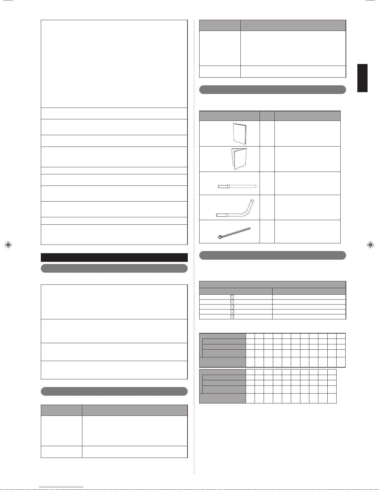
Accessories2. 3.
Use connecting parts as required.
Do not throw away the connecting parts until the installation has been complete.
Name and shape Q’ty Application
Specifi cations
manual
Installation
manual
Joint pipe A
Joint pipe B
Cable tie
—
1
(This book)
1
For connecting gas pipe
(Straight type)
1
For connecting gas pipe
(L type)
1
For binding power cable and transmission cable
4
ABOUT THE UNIT2.
Precautions for using the R410A refrigerant2. 1.
Pay careful attention to the following points :
Since the working pressure is 1.6 times higher than that of R22 models, some of the
piping and installation and service tools are special. (See the table in the SPECIAL
TOOLS FOR R410A section.)
Especially, when replacing a conventional refrigerant (other than R410A) model
with a new refrigerant R410A model, always replace the conventional piping and
fl are nuts with the R410A piping and fl are nuts.
Models that use refrigerant R410A have a different charging port thread diameter
to prevent erroneous charging with R22, R407C and for safety. Therefore, check
beforehand. [The charging port thread diameter for R410A is 1/2 UNF 20 threads
per inch.]
Be more careful than the installation of the refrigerant (other than R410A) models,
not to enter foreign matters (oil, water, etc.) and other refrigerant into the piping.
Also, when storing the piping, securely seal the openings by pinching, taping, etc.
When charging the refrigerant, take into account the slight change in the composition of the gas and liquid phases, and always charge from the liquid phase side
whose composition is stable.
Special tools for R410A2. 2.
Tool name Contents of change for R22 tool
Pressure is huge and cannot be measured with a conventional (R22) gauge. To prevent erroneous mixing of other
Gauge manifold
Charging hose
refrigerants, the diameter of each port has been changed.
It is recommended to use a gauge manifold with a high
pressure display range -0.1 to 5.3 MPa and a low pressure
display range -0.1 to 3.8 MPa.
To increase pressure resistance, the hose material and
base size were changed.
Combinations2. 4.
A maximum of 3 outdoor units can be connected to 1 refrigerant system.
The combination of outdoor units per refrigerant system and the number of indoor units
that can be connected are as follows:
Outdoor Unit
Model Name Nominal System Capacity (HP)
A72LALH 8
AJ
AJ
A90LALH 10
AJ
108LALH 12
AJ
126LALH 14
144LALH 16
AJ
Installation space combination
Combination (HP) 8 10121416182022242628
Outdoor Unit 1 (HP) 8 10121416101212121416
Outdoor Unit 2 (HP) –––––8810121212
Outdoor Unit 3 (HP) –––––––––––
Maximum Connectable
Indoor Unit
Combination (HP) 30 32 34 36 38 40 42 44 46 48
Outdoor Unit 1 (HP) 16 16 12 12 14 16 16 16 16 16
Outdoor Unit 2 (HP) 14 16 12 12 12 12 14 16 16 16
Outdoor Unit 3 (HP) – – 10 12 12 12 12 12 14 16
Maximum Connectable
Indoor Unit
When connecting outdoor units, install the outdoor unit with the largest nominal system capacity nearest to the refrigerant pipe and indoor unit, followed by those with lesser nominal system
capacities. (Outdoor unit 1 ≥ Outdoor unit 2 ≥ Outdoor unit 3)
15 16 17 21 24 32 32 32 35 39 42
45 48 48 48 48 48 48 48 48 48
En-2

Energy-saving combination
Combination (HP) 8 10121416182022242628
Outdoor Unit 1 (HP) ––––8––1481012
Outdoor Unit 2 (HP) ––––8––8888
Outdoor Unit 3 (HP) ––––––––888
Maximum Connectable
Indoor Unit
Combination (HP) 30 32 34 36 38 40 42 44 46 48
Outdoor Unit 1 (HP) 14 12 14 14 – 14 14 16 – –
Outdoor Unit 2 (HP) 8 12 12 14 – 14 14 14 – –
Outdoor Unit 3 (HP) 8888–121414––
Maximum Connectable
Indoor Unit
* Means that the energy-saving combination is unavailable.
When connecting outdoor units, install the outdoor unit with the largest nominal system capacity nearest to the refrigerant pipe and indoor unit, followed by those with lesser nominal system
capacities. (Outdoor unit 1 ≥ Outdoor unit 2 ≥ Outdoor unit 3)
* * * * 30 * * 33 36 39 42
45 48 48 48 * 48 48 48 * *
Optional parts2. 5.
CAUTION
The following parts are optional parts specifi c to R410A refrigerant.
Do not use parts other than those listed below.
Outdoor unit branch kit2. 5. 1.
Model Total cooling capacity of indoor unit (kW)
UTP-CX567A, UTR-CP567X ALL
CAUTION
Install the unit in an area that has no heat sources, vapors, or the risk of the leakage
of fl ammable gas in the vicinity.
Install the unit in an area that is away from the exhaust or vent ports that discharge
vapor, soot, dust, or debris.
Install the indoor unit, outdoor unit, power supply cable, transmission cable and
remote control cable at least 1 meter away from a television or radio.
The purpose of this is to prevent TV reception interference or radio noise. (Even if
they are installed more than 1 meter apart, you could still receive noise under some
signal conditions.)
Keep the length of the piping of the indoor and outdoor units within the allowable
range.
For maintenance purposes, do not bury the piping.
Drain processing3. 2.
The drain water is discharged from the bottom of the equipment. Construct a drain •
ditch around the base and discharge the drain water properly.
When installing on a roof, perform fl oor waterproofi ng properly.•
Drain processing:
The drain water from the base of the outdoor unit may generate during operations.•
Perform drain processing, as necessary.
When you want to prevent the drain water from leaking at the perimeter, construct •
a ditch for the drain water as shown in the fi gure.
Provide a central drain pan, as necessary.•
Outdoor unit
50mm or
more
Separation tube2. 5. 2.
Model Total cooling capacity of indoor unit (kW)
UTP-AX090A , UTR-BP090X 28.0 or less
UTP-AX180A , UTR-BP180X 28.1 to 56.0
UTP-AX567A , UTR-BP567X 56.1 or more
Header2. 5. 3.
3-6 branches 3-8 branches Total cooling capacity of indoor unit (kW)
UTR-H0906L UTR-H0908L 28.0 or less
UTR-H1806L UTR-H1808L 28.1 to 56.0
INSTALLATION WORK3.
Please obtain the approval of the customer when selecting the location of installation
and installing the main unit.
Selecting an installation location3. 1.
WARNING
Install the unit in a location that can withstand its weight, and where it will not topple
or fall.
Calculate the proper refrigerant concentration if you will be installing it in an enclosed location.
Total amount of replenished refrigerant in refrigerant facility (kg)
Capacity of smallest room where unit is installed (m3)
If the results of the calculation exceed the concentration limit, increase the room
surface area or install a ventilation duct.
≤
Refrigerant concentration (kg/m3)
(0.3kg/m3)
CAUTION
Select an installation location by observing the following precautions:
Install the unit level. (Within 3 degrees)
Install this unit in a location with good ventilation.
If the unit must be installed in an area within easy reach of the general public, install
as necessary a protective fence or the like to prevent their access.
Install the unit in an area that would not inconvenience your neighbors, as they could
be affected by the airfl ow coming out from the outlet, noise, or vibration.
If it must be installed in proximity to your neighbors, be sure to obtain their approval.
If the unit is installed in a cold region that is affected by snow accumulation, snow fall,
or freezing, take appropriate measures to protect it from those elements.
To ensure a stable operation, install inlet and outlet ducts.
Install the unit in an area that would not cause problems even if the drain water is
discharged from the unit. Otherwise, provide drainage that would not affect people or
objects.
10mm or more
Installation dimensions3. 3.
CAUTION
When installing the outdoor unit, pay attention to the following items.
Provide suffi cient installation space, such as transportation route, maintenance
space, ventilation space, refrigerant piping space, and passageways.
Pay attention to the specifi cations of the installation space as shown in the fi gure.
If the unit is not installed according to specifi cations, it may cause short circuit or
poor performance. The unit may be prone to lapse into non-operation due to high
pressure protection.
Do not place obstructions in the air fl ow outlet direction. If there is an obstruction in
the outlet direction, install an outlet duct.
When there is a wall in front of the unit, provide a space of 500mm or more as
maintenance space.
When there is a wall at the left side of the unit, provide a space of 30mm or more
as maintenance space.
An outdoor temperature of 35 degrees in air-conditioned operation is assumed for
the installation space in this item. If the outdoor temperature exceeds 35 degrees
and the outdoor unit is operating at a load exceeding its rated ability, provide a
larger inlet space.
If you are installing more outdoor units than indicated here, please ensure suffi cient
space or consult your distributing agent as it may affect the performance due to
short circuit and other problems.
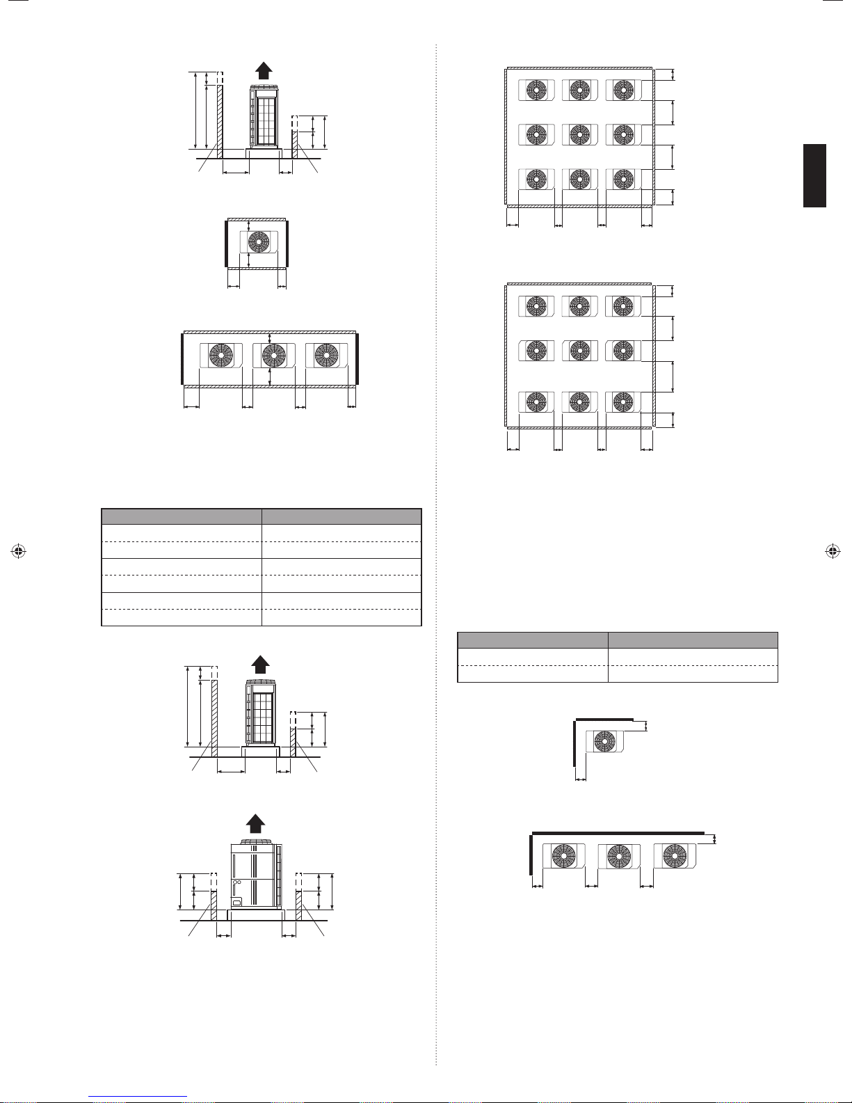
When install near by limited height wall3. 3. 1.
Single and multiple installations(1)
There are no restrictions on the height of the side wall.•
Provide installation spaces L1 and L2 in accordance with the table below according •
to the wall height (front side, rear side) conditions.
Provide installation spaces other than L1 and L2 in accordance with the conditions •
shown in the fi gure below.
Ventilation resistance can be ignorable when the distance from a wall or product, •
etc. is larger than 2m.
Wall height condition Necessary installation space
When H1 is 1500 (mm) or less L1 ≥ 500 (mm)
When H1 is 1500 (mm) or more L1 ≥ 500+h1÷2 (mm)
When H2 is 500 (mm) or less L2 ≥ 100 (mm)
When H2 is 500 (mm) or more L2 ≥ 100+h2÷2 (mm)
En-3
1Fig.
<Front> <Rear>
<Side view>
J
6 Fig.
<Top view>
L4
*
Wall
2 Single installationFig.
<Front>
3 Multiple installationsFig.
<Rear>
<Front>
30mm or
more
Concentrated installation(2)
Provide installation spaces L3, L4, and L5 in accordance with the table below ac-•
cording to the wall height (front side, rear side) conditions.
Provide installation spaces other than L3, L4, and L5 in accordance with the condi-•
tions shown in the fi gure below.
Ventilation resistance can be ignorable when the distance from a wall or product, •
etc. is larger than 2m.
Wall height condition Necessary installation space
When H3 is 1500 (mm) or less L3 ≥ 500 (mm)
When H3 is 1500 (mm) or more L3 ≥ 500+h3÷2 (mm)
When H4 is 500 (mm) or less L4 ≥ 200 (mm)
When H4 is 500 (mm) or more L4 ≥ 200+h4÷2 (mm)
When H5 is 500 (mm) or less L5 ≥ 200 (mm)
When H5 is 500 (mm) or more L5 ≥ 200+h5÷2 (mm)
4Fig.
<Front>
.
<Top view>
<Rear>
30mm or more 10mm or more
.
.
<Top view>
20mm or
more
<Side view>
.
.
.
20mm or
more
J
Wall
<Rear>
*
10mm or
more
J
*
.
Wall
5 Fig.
<Front view>
J
*
.
Wall
800mm
or more
800mm
or more
L3
20mm or
more
7 Fig.
20mm or
L5
more
20mm or
more
<Top view>
20mm or
more
L5L5
L4
500mm
or more
1000mm
or more
L3
L5
When install near unlimited height wall3. 3. 2.
Single and multiple installations(1)
There are no restrictions on the height of the wall.•
The wall (without height restrictions) must not exist on the both sides (left / right) •
of outdoor unit. Also, must not exist on the both sides (front / rear) of outdoor
unit.
Provide installation spaces other than L6 in accordance with the conditions •
shown in the fi gure below.
Ventilation resistance can be ignorable when the distance from a wall or prod-•
uct, etc. is larger than 2 m.
When installing with the REAR of the outdoor unit facing the wall side
Condition Necessary installation space
When B ≥ 400 (mm) L6 ≥ 200 (mm)
When 20 ≤ B < 400 (mm) L6 ≥ 200 + (400-B) ×3 (mm)
8 Single installationFig.
<Rear>
<Front>
9 MFig. ultiple installations
<Rear>
200mm
or more
<Top view>
<Top view>
100mm
or more
L6
h5
H5
500
Wall Wall
L5
L5
h5
500
<Front>
H5
200mm
or more
B
B
En-4

800mm
or more
200mm
or more
When installing with the FRONT of the outdoor unit facing the wall side
10 Fig.
11 Fig.
Wall
200mm
or more
Concentrated Installation(2)
The wall (without height restrictions) must not exist on the both sides (left / right) of •
outdoor unit. Also, must not exist on the both sides (front / rear) of outdoor unit.
Ventilation resistance can be ignorable when the distance from a wall or product, •
etc. is larger than 2m.
12 Fig.
200mm 200mm
Example :
When B is made 200mm
L6 ≥ 200+(400-200)×3=800mm
<Top view>
Wall
200mm or more
20mm or
more
<Top view>
<Top view>
20mm or
more
Wall
500mm
or more
Wall
500mm
or more
400mm
or more
800mm
or more
When there are obstacles above the product3. 3. 3.
When there are obstacles above the product, keep the
minimum installation height as shown in the fi gure and
install the outlet duct.
When installing the outlet duct, you must set the high
static pressure mode with the push-button switch.
(Similar when installing anti-snow hood)
Setting high static pressure mode
Follow the instructions in the table below to set the high
static pressure mode.
Condition
Static Pressure (SP) *1 :
0 ≤ SP ≤ 30 (Pa)
Static Pressure (SP)
30 < SP ≤ 80 (Pa)
Static pressure is the air fl ow resistance that includes *1.
the discharge duct resistance & the other additional resistance like discharge grill
and so on.
Refer to the section on Push Switch Setting in “Chapter 7 Field Setting”.*2.
High static pressure mode
setting
Set to Mode 1
*1
:
Set to Mode 2
*2
Outlet duct
Transportation the outdoor unit3. 4.
Product mass (kg)
A72LALH 220
AJ
□
A90LALH 220
AJ
□
AJ
108LALH 275
□
AJ
126LALH 303
□
AJ
144LALH 303
□
Hoisting method
When hanging the outdoor unit and conveying it to installation location, hang the •
unit with rope by passing through the 4 opening holes on bottom of front and rear
side as shown in fi gure.
Use 2 ropes at least 8m long. If used shorter length, it may cause to damage to the •
unit
.
Use the suffi ciently strong rope to bear the unit’s weight.•
Place the protective board or fi ller cloth at the place where the cabinet may come •
into contact with rope to prevent from damages. Without using them, cabinet may
cause to damage or deform.
During the hanging unit, make sure to keep the unit level to prevent from falling.•
To prevent an unit swing accident or falling down of the unit, do not apply any •
impact to the unit when it is hanging.
500mm
or more
1000mm
or more
13Fig.
1000mm
or more
400mm
or more
400mm
or more
400mm
or more
<Top view>
400mm
or more
800mm
or more
400mm
or more
500mm
or more
1000mm
or more
protective boards
opening space
Lifting by forklift
When using the forklift to lift the unit, pass the forklift arms through the opening •
space as shown in below.
Front : Bottom of the wooden delivery pallet.
Side : Space between pallet and cabinet.
(Enable to remove the pallet from cabinet.)
Be careful not to damaged.•
Lifting by forklift (Manual forklift: hand-fork)
When using the manual forklift to lift the unit, pass the forklift arms through to the •
opening space between pallet and cabinet from side.
En-5

SYSTEM CONFIGURATION4.
System confi guration4. 1.
<Front>
Fork (Forklift)
Delivery pallet
<Side>
Fork (Forklift) or
Fork (Manual forklift)
Installation the unit3. 5.
Install the unit level. (within 3 degrees).•
Install 4 or more anchor bolts at the 8 locations indicated by arrows (Fig. A).•
Place the left and right anchor bolts at a distance further away than the dimensions •
of A in the Table A.
(Excluding the case where anchor bolts are installed at 8 places.)
AFig.
Hole: 12 × 17
(8 places)
80
Table.A
Model name A B
AJ
A72LALH 610 930
□
A90LALH 610 930
AJ
□
108LALH 610 930
AJ
□
126LALH 920 1240
AJ
□
144LALH 920 1240
AJ
□
To minimize vibration, do not install the outdoor unit directly on the ground.•
Instead, install it on top of a fi rm platform (such as concrete block). (Fig. B)
The foundation base should be able to support the product and the foot width of •
the product should be more than 46.5mm.
Depending on the installation condition, vibration during the operation of the unit •
may cause noise and vibration.
Install vibration-proofi ng materials (such as rubber pads).
Consider the removal space of the connection piping when installing the founda-•
tion.
Secure the equipment fi rmly with anchor bolts, washers, and nuts.•
BFig.
GOODPROHIBITED GOOD
B
A
Bottom view
(Unit: mm)
160160
732
80
Bolt (M10)
765
CAUTION
When connecting multiple outdoor units, set the nearest outdoor unit to the indoor •
unit on the refrigerant pipe as the master unit.
When connecting multiple outdoor units, install the outdoor unit with the largest •
nominal system capacity nearest to the indoor unit on the refrigerant pipe, followed by those with less nominal system capacities.
[Capacity: Master ≥ Slave]
Always keep to the limit on the total amount of refrigerant. Exceeding the limit •
on the total amount of refrigerant when charging will lead to malfunction.
In case of 1 outdoor unit connected A)
A Fig.
f
I.U.
I.U. I.U. I.U.
Allowable pip length (actual pipe length)•
Between master outdoor unit and the
farthest indoor unit
Between the fi rst separation tube and the
farthest indoor unit
Total pipe length 700 m or less Total
Allowable height difference•
Between outdoor unit and indoor unit (When
indoor unit is installed below)
Between outdoor unit and indoor unit (When
outdoor unit is installed below)
Between indoor units 15 m or less H2, H3
Total refrigerant amount : 31.5 kg or less•
In case of 2 outdoor units connected B)
B Fig.
O.U.-1
(Master)
e
I.U.
O.U.
(Master)
O.U. :Outdoor unit
f
O.U.-2
(Slave)
p
I.U. :Indoor unit
H3
O.U. :Outdoor unit
I.U. :Indoor unit
b
I.U.
I.U. I.U.
150 m or less
60 m or less f, p
50 m or less
40 m or less
a
I.U. I.U. I.U. I.U.
H4
a
I.U.
H1
H2
I.U.
a+p
H1
a+f
H1
*Do not use a four-corner support foundation.
CFig.
When installing piping from the bottom
of the outdoor units,
the required space
under the outdoor
unit ≥ 200mm.
* Install the branch
kit horizontally.
More than
200mm
I.U.
H2
a+e+f
a+e+p
I.U.
I.U.
I.U.
H3
Allowable pip length (actual pipe length)•
Between master outdoor unit and the
farthest indoor unit
Between the fi rst separation tube and the
farthest indoor unit
Total pipe length 1000 m or less Total
Between outdoor unit and outdoor unit
branch kit
150 m or less
60 m or less f, p
3 m or less a, b
En-6

Allowable height difference•
Between outdoor unit and indoor unit (When
indoor unit is installed below)
Between outdoor unit and indoor unit (When
outdoor unit is installed below)
50 m or less
40 m or less
Between indoor units 15 m or less H2, H3
Between outdoor units 0.5 m or less H4
Total refrigerant amount : 63 kg or less•
Outdoor unit capacity : Master ≥ Slave•
In the case of 3 outdoor units connected C)
CFig.
O.U.-3
O.U.-1
(Master)
O.U.-2
(Slave1)
a
d
e
H4
b
c
(Slave2)
f
O.U. :Outdoor unit
I.U. :Indoor unit
H1
p
H2
H3
Allowable pip length (actual pipe length)•
Between master outdoor unit and the
farthest indoor unit
Between the fi rst separation tube and the
farthest indoor unit
150 m or less
60 m or less f, p
a+e+f
a+e+p
Total pipe length 1000 m or less Total
Between outdoor unit and outdoor unit
branch kit
Between the farthest outdoor unit and the
fi rst outdoor unit branch kit
3 m or less a, b, c
12 m or less
b+d
c+d
Allowable height difference•
Between outdoor unit and indoor unit (When
indoor unit is installed below)
Between outdoor unit and indoor unit (When
outdoor unit is installed below)
50 m or less
40 m or less
Between indoor units 15 m or less H2, H3
Between outdoor units 0.5 m or less H4
Total refrigerant amount : 94.5 kg or less•
Outdoor unit capacity : Master ≥ Slave 1 ≥ Slave 2•
If the outdoor temperature during cooling operation is expected to be –5 °C
• NOTE)
or less, do not install the outdoor unit lower than the indoor unit
• Please refer to “8.3.2. Checking total amount of refrigerant and calculating the amount of refrigerant charge to be added” for the total amount of
refrigerant.
.
(Wall thickness and pipe material for each diameter)
Outside Diameter mm 6.35 9.52 12.70 15.88 19.05 22.22 28.58 34.92 41.27
H1
Wall Thick ness*3mm 0.8 0.8 0.8 1.0 1.2 1.0 1.0 1.2 1.43
Material
Allowable tensile stress ≥ 33 (N/mm*1.
Allowable tensile stress ≥ 61 (N/mm*2.
Endurance pressure of the pipes 4.2MPa*3.
Please select the pipe size in accordance with local rules.
JIS H3300 C1220T-O or equiva-
COPPER
lent
2
)
2
)
*1
JIS H3300 C1220T-H or
COPPER
equivalent
*2
A (Between outdoor unit and outdoor unit branch kit)Tab le.
Outdoor unit cooling
HP
capacity (kW)
8
10
12
14
16
22.4 12.70 (1/2") 22.22 (7/8")
28.0 12.70 (1/2") 22.22 (7/8")
33.5 12.70 (1/2") 28.58 (1-1/8")
40.0 12.70 (1/2") 28.58 (1-1/8")
45.0 12.70 (1/2") 28.58 (1-1/8")
Outside diameter (mm)
Liquid pipe Gas pipe
*4
Branch kit
UTP-DX567A,
UTR-CP567X
For the installation method, refer to “5.4. Multiple connections”.*4.
B (Between outdoor unit branch kits or outdoor unit branch kit and Table.
fi rst separation tube)
Tot al co oling ca pa ci ty
of outdoor unit (kW)
Outside diameter (mm)
Liquid pipe Gas pipe
22.4 to 28.0 12.70 (1/2") 22.22 (7/8")
28.1 to 45.0 12.70 (1/2") 28.58 (1-1/8")
45.1 to 56.0 15.88 (5/8") 28.58 (1-1/8")
56.1 to 80.0 15.88 (5/8") 34.92 (1-3/8")
80.1 to 96.0 19.05 (3/4") 34.92 (1-3/8")
96.1 or more 19.05 (3/4") 41.27 (1-5/8")
C (Between separation tubes)Tab le.
Total cooling capacity
of indoor unit (kW)
Outside diameter (mm)
Liquid pipe Gas pipe
4.4 to 11.1 9.52 (3/8") 15.88 (5/8")
11.2 to 13.9 9.52 (3/8") 19.05 (3/4")
14.0 to 28.0 12.70 (1/2") 22.22 (7/8")
H1
28.1 to 44.7 12.70 (1/2") 28.58 (1-1/8")
44.8 to 56.0 15.88 (5/8") 28.58 (1-1/8")
56.1 to 80.0 15.88 (5/8") 34.92 (1-3/8")
80.1 to 95.0 19.05 (3/4") 34.92 (1-3/8")
95.1 or more 19.05 (3/4") 41.27 (1-5/8")
* If the selected pipe diameter between separation tubes (based on table "C") becomes
larger than the pipe diameter between outdoor unit branch kit and the fi rst separation
tube (based on table "B"), please select the pipe whose diameter is equal to the one
between outdoor unit branch kit and the fi rst separation tube.
(If pipe diameter C > B, select pipe size from table B)
* Total cooling capacity of indoor unit" is the total value for the cooling capacity of indoor
unit connected downstream.
Pipe selection4. 2.
CAUTION
This unit is designed specifi cally for use with the R410A refrigerant. Pipes for
R407C or R22 may not be used with this unit. Do not use existing pipes. Improper
pipe selection will degrade performance.
unit
Slave
unit1
Indoor
unit
Slave
unit2
Separation tube
(optional)
Indoor
unit
Indoor
unit
Master
First separation
tube (optional)
Indoor
Indoor
unit
unit
unit
Outdoor unit
branch kit
(optional)
Indoor
En-7
Pipe size
(table A)
Pipe size
(table B)
Pipe size
(table C)
Pipe size
(table D)
D (Between separation tube to indoor unitTab le.
Model code
Cooling capacity of
indoor unit (kW)
)
Outside diameter mm (in)
Liquid pipe Gas pipe
07, 09, 12, 14 2.2, 2.8, 3.6, 4.0, 4.5 6.35 (1/4") 12.70 (1/2")
18, 24, 30 5.6, 7.1, 8.0, 9.0 9.52 (3/8") 15.88 (5/8")
36, 45, 54, 60 11.2, 12.5, 14.0, 18.0 9.52 (3/8") 19.05 (3/4")
72, 90 22.4, 25.0 12.70 (1/2") 22.22 (7/8")
Use a standard separation tube for pipe branching. Do not use a T tube as it does not
separate the refrigerant evenly.
E (Separation tube / Header)Tabl e.
Separation tube•
Total cooling capacity of indoor unit (kW) Separation tube
*5
28.0 or less UTP-AX090A or UTR-BP090X
28.1 to 56.0 UTP-AX180A or UTR-BP180X
56.1 or more UTP-AX567A or UTR-BP567X
 Loading...