

FujiFilm RYT-30, RCW-18A Installation Manual

- Continued on back -
SPLIT TYPE AIR CONDITIONER
Ceiling Suspension Type
INSTALLATION MANUAL
(PART NO. 9361156012-02)
For authorized service personnel only.
WARNING
SELECTING THE MOUNTING POSITION
WARNING
CAUTION
CAUTION
Hold the torque wrench at its grip, keeping it in the right
angle with the pipe as shown in Fig. 25, in order to tighten
the flare nut correctly.
CAUTION
Be sure to apply the pipe against the port on the indoor
unit correctly. If the centering is improper, the flare nut
cannot be tightened smoothly. If the flare nut is forced to
turn, the threads will be damaged.
WARNING
CAUTION
In order to check the drainage, be sure to use a level during installation of the indoor unit. If the installation site of
the indoor unit is not level, water leakage may occur.
WARNING
Install the unit where it will not be tilted by more
than 5°.
When installing the outdoor unit where it may
exposed to strong wind, fasten it securely.
(1)
(2)
(1)
(2)
Install the unit where it will not be tilted by more than 5°.
When installing the outdoor unit where it may exposed to
strong wind, fasten it securely.
The maximum lengths of this product are shown in table 3.
If the units are further apart than this, correct operation
can not be guaranteed.
CAUTION
(1) For the air conditioner to operate satisfactorily, install it as outlined in this installation manual.
(2) Installation work must be performed in accordance with national wiring standards by authorized personnel only.
(3) Do not turn on the power until all installation work is complete.
•
Be careful not to scratch the air conditioner when handling it.
•
After installation, explain correct operation to the customer, using the operating manual.
•
Let the customer keep this installation manual because it is used when the air conditioner is serviced or moved.
Install at a place that can withstand the weight of the
indoor and outdoor units and install positively so that
the units will not topple or fall.
Do not install where there is the danger of combustible gas leakage.
Do not install the unit near a source of heat, steam,
or flammable gas.
If children under 10 years old may approach the unit,
take preventive measures so that they cannot reach
the unit.
Decide the mounting position with the customer as follows:
1. INDOOR UNIT
Install the indoor unit level on a strong wall which is not subject to
vibration.
The inlet and outlet ports should not be obstructed : the air should
be able to blow all over the room.
Do not install the unit where it will be exposed to direct sunlight.
Install the unit where connection to the outdoor unit is easy.
Install the unit where the drain pipe can be easily installed.
Take servicing, etc. into consideration and leave the spaces shown
in (Fig. 2 or 3). Also install the unit where the filter can be removed.
(1)
(2)
(3)
2. OUTDOOR UNIT
STANDARD PARTS
The following installation parts are furnished. Use them as required.
INSTALLATION PROCEDURE
Install the air conditioner as follows:
Name and Shape Q’ty Application
Remote
control unit
1
1
2
1
Drain hose insulation3Adhesive type 70 × 230
Remote
control
unit holder
1
Tapping screw
(ø3 x 12)
For remote control unit
holder installation
Battery (penlight)
4
Coupler heat insulator (large) For indoor side pipe joint
(large pipe)
Large
4
Small
4
Nylon fastener
Auxiliary pipe assembly
For fixing the coupler heat
insulator
1
For connecting the piping
Special nut B
(small flange)
4
For installing indoor unit
Special nut A
(large flange)
4
For installing indoor unit
VT wire
For fixing the drain hose
L 280 mm
1
Coupler heat insulator (small) For indoor side pipe joint
(small pipe)
1
Installation
template
For positioning the indoor
unit
Diameter
Large
Small
5/8”(ø15.88 mm)
3/8”(ø9.53 mm)
INDOOR UNIT ACCESSORIES
CONNECTION PIPE REQUIREMENT
•
Use 0.7 mm to 1.2 mm thick pipe.
•
Use pipe with water-resistant heat insulation.
•
Electric wire size and fuse/breaker capacity:
INDOOR UNIT INSTALLATION
PREPARING INDOOR UNIT
INSTALLATION
You can use the accessory template to help you install the indoor
unit. The template helps you determine the appropriate locations for
suspension bolts and pipe openings (drain pipe and connection cord).
Fig. 6
1. LOCATION OF CEILING SUSPENSION BOLTS
Fig. 7
[For Half-Concealed Installation]
Suspension-bolt pitch should be as shown in Fig. 7.
Fig. 8
2. SELECT PIPING DIRECTION.
Select connection piping and drain piping directions (Fig.9).
Fig. 9
[For 4 Left rear piping, 5 Left piping]
Transfer the Drain cap and Drain cap seal.
Fig. 10
DRILLING THE HOLES AND ATTACHING THE SUSPENSION BOLTS
Drill ø25mm holes at the suspension-bolt locations.
Install the bolts, then temporarily attach Special nuts A and B
and a normal M10 nut to each bolt. (The two special nuts are provided with the unit. The M10 nut must be obtained locally.) Refer
to Fig. 11.
Fig. 11
[If using anchor bolts]
Drill holes for anchor bolts at the locations at which you will set
the suspension bolts. Note that anchor bolts are M10 bolts (to be
obtained locally).
Install the anchor bolts, then temporarily attach special nut "B"
(included) and a locally-procured M10 nut to each of the bolts.
(See Fig. 12.)
Fig. 12
4. INSTALLING THE INDOOR UNIT
Lift unit so that suspension bolts pass through the suspension fittings at the sides (four places), and slide the unit back. (See Fig.
14.)
Fig. 13
Fig. 14
Fasten the indoor unit into place by tightening-up the special “B”
bolts and the M10 nuts. Make sure that unit is secure and will not
shift back and forth.
[For Half-Concealed Installation]
When installing the indoor unit in a semi-concealed orientation, make
sure to reinforce the insulation of the unit on all sides. Drops of water
may fall from the unit if it is not thoroughly insulated.
Fig. 15
2. FLARE PROCESSING
Cut the connection pipe with pipe cutters so that the pipe is not
deformed.
Holding the pipe downward so that cuttings cannot enter the pipe,
remove the burrs.
Remove the flare nut from the indoor unit pipe and outdoor unit
and assemble as shown in (Table 4) and insert the flare nut onto
the pipe, and flare with a flaring tool.
Check if the flared part “L” (Fig. 19) is spread uniformly and that
there are no cracks.
Table 4
(1)
(2)
(3)
(4)
CONNECTING THE PIPING
Fig. 2
[FOR HALF CONCEALED INSTALLATION]
Fig. 3
Fig. 1
If possible, do not install the unit where it will exposed to direct
sunlight. (If necessary, install a blind that does not interfere with the
air flow.)
Install the outdoor unit in a place where it will be free from being dirty or getting wet by rain as much as possible.
Install the unit when connection to the indoor unit is easy.
During heating operation, drain water flows from the outdoor unit.
Therefore, install the outdoor unit in a place where the drain water
flow will not be obstructed. (Heat & Cool model (Reverse cycle) only)
Do not place animals and plants in the path of the warm air.
Take the air conditioner weight into account and select a place where
noise and vibration are small.
Select a place so that the warm air and noise from the air conditioner
do not disturb neighbors.
Provide the space shown in Fig. 4 so that the air flow is not blocked.
Also for efficient operation, leave open three of the four directions
front, rear, and both sides.
Fig. 4
Table 1
(1)
(2)
(3)
(4)
(5)
(6)
(7)
(8)
Use for air conditioner
operation
For remote control unit
For mounting the remote
control unit
Power supply cord (mm2)
Connection cord (mm
2
)
MAX
MIN
MAX
MIN
3.5
3.0
1.5
1.0
Fuse/Breaker capacity (A) 30
ELECTRICAL REQUIREMENT
•
•
Always use H07RN-F or equivalent as the cord.
Install the disconnect device with a contact gap of at least 3 mm
nearby the units. (Both indoor unit and outdoor unit)
Table 2
(1)
(2)
(3)
(4)
(1)
(2)
(1)
(2)
(1)
(2)
(1)
(2)
REMOVE THE INTAKE GRILLE AND SIDE COVER.
Remove the two Air filters (Fig.5).
Remove the two Intake grilles (Fig.5).
For 4 Left rear drain and 5 Left drain: Remove air filters and
intake grilles at three places. (Refer to "2 INDOOR UNIT
INSTALLATION".)
Remove the Side cover A (Right side) and Side cover B (Right
and Left side).
For 5 Left drain : Remove both the Side cover A (Right and
Left side). (Refer to "2 INDOOR UNIT INSTALLATION".)
This air conditioner can be set up to intake fresh air. For information about how to install for fresh-air intake, refer to "E FRESHAIR INTAKE".
Fig. 5
•
•
•
•
•
Anchor-Bolt Strength 980 to 1470 N (100 to 150 kgf)
Bolt Strength 980 to 1470 N (100 to 150 kgf)
Pipe
Small pipe
Large pipe
Flare nut
Small (width across flats 22 mm)
Large (width across flats 24 mm)
(1)
(2)
(3)
(4)
(5)
(6)
3.
Do not bend the pipes in an angle less than 90°.
When the pipes are bent and stretched repeatedly, the material will be
hardened, causing the pipes no longer be sent or stretched. Be sure to limit number of bending and stretchings to three times.
When bending the pipe, do not bend
it as is. The pipe will be collapsed. In
this case, cut the heat insulating pipe
with a sharp cutter as shown in Fig.
21, and bend it after exposing the
pipe. After bending the pipe as you
want, be sure to put the heat insulating pipe back on the pipe, and secure
it with tape.
4. CONNECTION PIPES
[Indoor unit side]
Remove the filter guide (Fig. 22).
Fig. 22
Attach the connection pipe. (Fig. 23)
Fig. 23
For 2 Top piping and 3 Right piping connections, use the Auxiliary pipe (large pipe) provided.
Fig. 24
When the flare nut is tightened properly by your hand, hold the boby side
coupling with a separate spanner, then tighten with a torque wrench. (Fig. 25)
Fig. 25
Table 5 : Flare nut tightening torque
[Outdoor unit side]
Tighten the flare nut of the connection pipe at the outdoor unit valve
connector. The tightening method is the same as that as at the indoor
side.
Fig. 26
Fig. 21
Hexagon wrench
1
For opening the refrigerant
valve on the outdoor unit
For power cord binding
Cable clip
2
1
For outdoor unit drain
piping work
[Heat & Cool (Reverse cycle)
model only]
Drain pipe
1
Drain cap
2
OUTDOOR UNIT ACCESSORIES
For fixing the valve cover
Tapping screw
(painted)
OUTDOOR UNIT INSTALLATION
1. OUTDOOR UNIT PROCESSING
When the outdor unit will be exposed to strong wind, fasten it with
bolts at the places indicated by the arrows. (Fig. 16)
Fig. 16
(1)
(2)
If this product is used in an area where
the temperature falls below freezing
for long periods of time, do not connect the drain pipe. Instead, allow the
water to drain into a drain pan.
CAUTION
2. OUTDOOR UNIT CONNECTION CORD AND
PIPE CONNECTION PREPARATIONS
Remove outdoor unit valve cover.
Fig. 17
Connect the piping, connection cord and power cord.
Fig. 18
Set the unit on a strong stand, such as one mode of concrete blocks to
minimize shock and vibration.
Do not set the unit directly on the ground because it will cause trouble.
•
•
99 ft (30 m)
82 ft (25 m)
49 ft (15 m)
1. LIMITATION OF REFRIGERANT PIPING LENGTH
Table 3
Cooling model
Heat & Cool model
(Reverse cycle)
Max length (L)
Max height difference (H)
Fig. 19
3. BENDING PIPES
The pipes are shaped by your hands. Be careful not to collapse them.
Fig. 20
Pipe
Small pipe
(9.53 mm dia.)
Large pipe
(15.88 mm dia.)
Tightening torque
310 to 350 kgf
•
cm (30.4 to 34.3 N
•
m)
750 to 800 kgf
•
cm (73.5 to 78.4 N
•
m)
1
4
3
2
Tapping screw
Air filter
Intake grille
Side cover B
(Left side)
INDOOR UNIT
Side cover A (Right side)
Side cover B (Right side)
INDOOR UNIT
Suspension bolt pitch 1600 mm
INDOOR UNIT (TOP VIEW)
30 mm
30 mm
Dimensions
(Space Required for
Installation)
Suspension bolt should
extend outward 30 to 75mm.
10 mm
155 mm
300 mm
Ceiling Opening: 1580mm
40 mm 40 mm
Ceiling panel
Ceiling Opening: 640mm
15 mm
Ceiling panel
Suspension bolt should
extend outward 30 to 50mm.
INDOOR UNIT
1 Right rear piping
2 Top piping
(Connection pipe only)
3 Right
piping
4 Left rear piping
(Drain pipe only)
5 Left piping
(Drain pipe only)
INDOOR UNIT (TOP VIEW)
Cut off the piping outlet cutting groove
with a hacksaw, etc.
Wall
Ceiling
M10 Anchor Bolt
(Obtained locally)
Ceiling
10 to 15 mm
Special nut B
(Included)
M10 Nut
(Obtained locally)
M10 Nut (Obtained locally)
10 to 15 mm
Special nut A (Included)
Ceiling panel
Special nut B (Included)
L dimension
Small pipe (9.53 mm dia)
1.8 to 2.0 mm
Large pipe (15.88 mm dia)
2.2 to 2.4 mm
Ceiling panel
3” (80 mm)
or over
INDOOR UNIT
6” (150 mm)
or over
Ceiling panel
0.4” (10 mm)
or over
Drilling position for piping
Drilling position for Suspension bolt
Ceiling
Wall
Template
Push cap all the way on
(as far as it will go).
Drain cap
Drain cap seal
Indoor unit
Drain pan
Drain cap seal
Drain cap
Wall
INDOOR UNIT
Ceiling panel
Ceiling
INDOOR UNIT
3” (80 mm)
or over
Ceiling
6” (150 mm)
or over
0.4” (10 mm)
or over
2 Top piping
3 Right piping
Large pipe
Large pipe
Auxiliary pipe (large pipe)
Indoor unit (rear)
Filter guide
Indoor unit
INDOOR UNIT
(Top view)
Wall
Ceiling panel
Glass wool insulate
(10 to 20mm thick)
Small pipe
Indoor unit
Large pipe
24” (600 mm)
or more
AIR
12”
(300 mm)
or more
12”
(300 mm)
or more
12”
(300 mm)
or more
24” (600 mm)
or more
31-21/32” (804 mm)
Drain pipe mounting hole
Bottom plate
Drain pipe
3/4” (19 mm)
13-7/64”
(333 mm)
Air flow
Drain cap
Bottom
Valve cover
take off direction
* After removing the screws,
remove valve cover
Valve cover
Valve
Pipe
Power cord
Connection
cord
(Small pipe)
(Large pipe)
Connection pipe
Flare nut
2-way valve
3-way valve
INDOOR UNIT
OUTDOOR UNIT
Connection cord
1.0 to 1.5 mm
2
(H07RN-F or equivalent)
Drain pipe
VP25 (General polyvinyl chloride pipe)
5/8” (ø15.88 mm)
3/8” (ø9.53 mm)
Power supply cord
3.0 to 3.5 mm
2
(H07RN-F or equivalent)
Power supply
1ø
•
220-240V • 50Hz
Special branch circuit breaker
(Fuse/Breaker capacity : 30A)
Tapping
screws
Insert
Slide up
Mount the Holder.1 Set the Remote Control
Unit.
2
To remove the Remote
Control Unit (when use
at hand.)
3
Tapping
screws
Tapping
screw
Insert
Mount the Holder.1 Set the Remote Control
Unit.
2
Atlach the unit to the
holder as shown.
3
Slide
START
STOP
START/STOP button
TEST RUN button
ABCD
Indoor unit
Coupler heat insulation (large)
Connection pipe (large)
Connection pipe (small)
Coupler heat insulation (small)
Indoor unit
Nylon fastner (large)
Nylon fastner (small)
Coupler heat
insulation
No gap
Arrange the drain pipe
lower than this portion.
Drain pipe
GOOD
Lifted up
BAD BAD
Wave
End in water
Supporter
5 to 6.5 ft
(1.5 to 2 m)
Indoor unit (drain port)
Insulation for Drain pipe
(To be obtained locally. Length should
be at least 8mm.)
Drain pipe insulation (accessories)
Drain pipe
Duct
Control box
Cover A
Control box
Tapping screw
Indoor unit
10 mm or over
Indoor unit
No gap
Drain pipe insulation
Drain pipe
Indoor unit
For half concealed
installation
Round duct (option parts)
Indoor unit (rear view)
VT wire
Drain hose
Refrigerant pipe
3-way valve
Blank cap
Charging valve
Cap
Service hose with
valve core
Outdoor unit
L
O
H
I
Gauge manifold
Vacuum pump
Service hose
Cable clip
Cable clip
After passing the connection
cord through the insulation
tube, fasten it with the cord
clamp
3
1
2
Valve
cover
Reinstall the
removed screws.
Accessory
part
Attach the
four fasteners.
Make longer
than the other
wires.
Insulation tube
Insulation tube
Power cord
Ground
Power cord
Terminal board
Control box
Cord clamp
Connection cord
(indoor unit and outdoor
unit connection cord)
Power supply
Power line
Control line
Indoor unit
side terminal
Outdoor unit
side terminal
EARTH
L
N
3
2
(N)
1
3
2
(N)
1
LN3
2
(N)
1
Cable clip
Control box
Connection cord
Terminal board
Earth screw
Cord clamp
To outdoor unit
Connection cord
Connection cord
Indoor unit
Printed circuit board
JM1
JM2
JM3
AUTORESTART
REMOCON 2
REMOCON 1
SWING SWING TIMER
OPERATION
MANUAL
AUTO
VERTICAL SWING lamp (Orange)
TIMER lamp (Green)
OPERATION lamp (Red)
ABCD
ABCD
Remote control unit
signal selector switch
Remote control unit
ACL button
PART NO. 9361156012-02
WARNING
(1)
(2)
(3)
(4)
(5)
Before starting work, check that power is not being
supplied to the outdoor unit.
Match the terminal board numbers and connection
cord colors with those of the outdoor unit.
Erroneous wiring may cause burning of the electric
parts.
Connect the connection cord firmly to the terminal
board. Imperfect installation may cause a fire.
Always fasten the outside covering of the connection cord with the cord clamp. (If the insulator is
chafed, electric leakage may occur.)
Always connect the ground wire.
CAUTION
When the voltage is low and the air conditioner is difficult to start, contact the power company the voltage
raised.
CAUTION
(1)
(2)
Check that the indoor unit correctly receives the signal
from the remote control unit, then install the remote
control unit holder.
Select the remote control unit holder selection site by
paying careful attention to the following:
Avoid places in direct sunlight.
Select a place that will not be affected by the heat
from a stove, etc.
WARNING
(1)
(2)
(3)
(4)
(5)
(6)
(7)
The rated voltage of this product is 220-240V AC
50Hz.
Before turning on verify that the voltage is within the
198V to 264V range.
Always use a special branch circuit and install a special
receptacle to supply power to the air conditioner.
Use a special branch circuit breaker and receptacle
matched to the capacity of the air conditioner.
(Fuse/Breaker capacity : 30 A)
The special branch circuit breaker is installed in the permanent wiring.
Always use a circuit that can trip all the
poles of the wiring and has an isolation distance of at
least 3mm between the contacts of each pole.
Perform wiring work in accordance with standards so
that the air conditioner can be operated safely and
positively.
Install a leakage special branch circuit breaker in
accordance with the related laws and regulations
and electric company standards.
WARNING
(1)
(2)
(3)
(4)
(5)
Before starting work, check that power is not being
supplied to the outdoor unit.
Match the terminal board numbers and connection
cord colors with those of the outdoor unit.
Erroneous wiring may cause burning of the electric
parts.
Connect the connection cord firmly to the terminal
board. Imperfect installation may cause a fire.
Always fasten the outside covering of the connection cord with the cord clamp. (If the insulator is
chafed, electric leakage may occur.)
Always connect the ground wire.
CAUTION
(1)
(2)
When removing the cabinet (iron plate), be careful not
to damage the indoor unit internal parts and surrounding area (outer case).
When processing the cabinet (iron plate), be careful
not to injure yourself with burrs, etc.
CAUTION
After connecting the piping, check the joints for gas
leakage with gas leak detector.
CAUTION
Use 1.0 mm2 to 1.5 mm2 H07RN-F or equivalent as the
connection cord.
Select power cable matched to the fuse capacity.
(Install in accordance with standard.)
Use VW-1, 12 mm diameter, 0.5 to 1.0 mm thick, PVC
tube as the insulation tube.
(1)
(2)
(3)
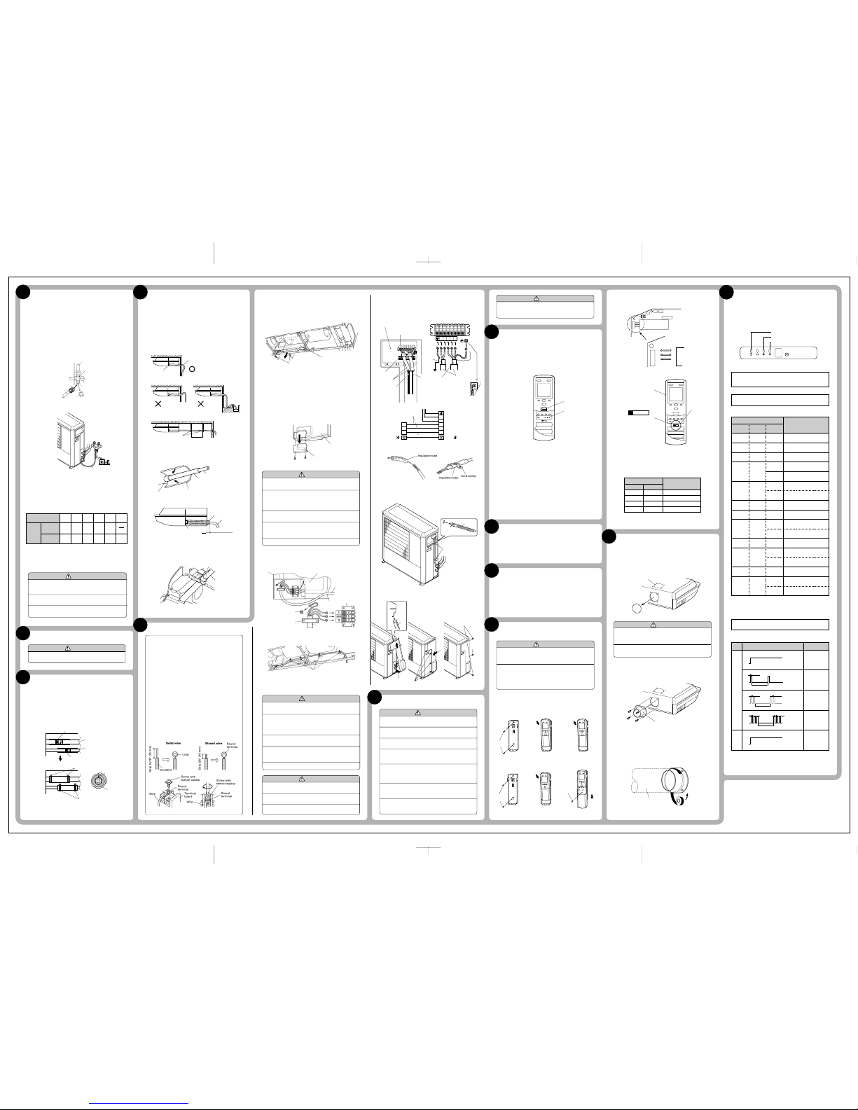
Error display
OPERATION
lamp
TIMER
lamp
VERTICAL
SWING lamp
Error contents
Model information abnormal
(permanent type)
Drain abnormal (permanent
type)
Indoor fan abnormal
Room air temperature
thermistor open circuit
Room air temperature
thermistor short circuit
Piping thermistor open
circuit
Piping thermistor short
circuit
Serial communications
abnormal
Reverse phase wire
connection abnormal
Outdoor heat exchange
thermistor open circuit
Outdoor heat exchange
thermistor short circuit
High pressure abnormal
Outdoor discharge
thermistor open circuit
Outdoor discharge
thermistor short circuit
Discharge temperature
abnormal
Outdoor air temperature
thermistor open circuit
Outdoor air temperature
thermistor short circuit
Goes off
Goes off
Goes off
Goes off
Blinks
Goes off
Blinks
Goes off
Goes off
Goes off
Blinks
Goes off
Goes off
Blinks
Goes off
Goes off
Blinks
Blinks
Blinks
Blinks
Blinks
Blinks
Blinks
Pulses
2 times
Pulses
3 times
Pulses
6 times
Pulses
5 times
Pulses
7 times
Pulses
4 times
Blinks
Pulses
4 times
Pulses
6 times
Pulses
2 times
Pulses
3 times
Pulses
5 times
Blinks
Blinks
Blinks
Blinks
Blinks
Blinks
(1)
POWER
To end test operation, press the remote control unit START/STOP
button.
(When the air conditioner is run by pressing the remote control
unit TEST RUN button, the OPERATION and TIMER lamps will
simultaneously flash slowly.)
1. INDOOR UNIT
Is operation of each button on the remote control unit normal?
Does each lamp light normally?
Do not air flow direction flap and louvers operate normally?
Is the drain normal?
2. OUTDOOR UNIT
Is there any abnormal noise and vibration during operation?
Will noise, wind, or drain water from the unit disturb the
neighbors?
Is there any gas leakage?
•
•
•
(1)
(2)
(3)
(4)
(1)
(2)
(3)
CUSTOMER GUIDANCE
FINISHING
Explain the following to the customer in accordance with the operating
manual:
Starting and stopping method, operation switching, temperature
adjustment, timer, air flow adjustment, and other remote control
unit operations.
Air filter removal and cleaning.
Give the operating and installation manuals to the customer.
(1)
(2)
(3)
REMOTE CONTROL UNIT
INSTALLATION
FRESH-AIR INTAKE
A ERROR DISPLAY
ELECTRICAL WIRING
(1)
(2)
(3)
(4)
(1)
(2)
(3)
(4)
GAS LEAKAGE INSPECTION
INSTALLING THE COUPLER HEAT
INSULATION
After checking for gas leaks, insulate by wrapping insulation around the
two parts (large and small) of the indoor unit coupling, using the coupler
heat insulation.
After installing the coupler heat insulation, wrap both ends with vinyl
tape so that there is no gap.
Secure both ends of the heat insulation material using nylon fasteners.
Fig. 29
When using an auxiliary pipe, make sure that the fastener
used is insulated in the same way.
DRAIN PIPING
Install the drain pipe with downward gradient (1/50 to 1/100) and so
there are no rises or traps in the pipe.
Use general hard polyvinyl chloride pipe (VP25) [outside diameter 38
mm].
During installation of the drain pipe, be careful to avoid applying
pressure to the drain port of the indoor unit.
When the pipe is long, install supporters (Fig. 30).
Do not perform air bleeding.
Always heat insulate (8mm or over thick) the indoor side of the drain
pipe.
Fig. 30
Install insulation for the drain pipe. (See Figs. 31 and 32.)
Cut the included insulation material to an appropriate size and
adhere it to the pipe.
Fig. 31
Fig. 32
If "1 Right rear piping": fasten the drain pipe with VT wire so
that the pipe slopes correctly within the indoor unit. (Fig. 33)
Fig. 33
••
•
•
•
•
•
(2)
1. INDOOR UNIT SIDE
Remove the two tapping screws and pull the control box downward. (Fig. 35)
Fig. 35
Remove the Cover A and install the Connection cord (Fig. 36 and
37)
After wiring is complete, clamp the Connection cord with the
Cord clamp (Fig. 37)
Reattach Cover A. Then fasten the control box back into its
original position using the two tapping screws.
Attach the connection cord and cable clips. Make sure that they
are positioned so that they will not interfere with opening and
closing of the intake grille or with removal and installation of
the air filters. (Fig. 37)
Fig. 36
Fig. 37
(1)
2. OUTDOOR UNIT SIDE
(2)
(3)
(4)
(5)
1. REMOTE CONTROL UNIT HOLDER INSTALLATION
Install the remote control unit holder to a wall or pillar with the
tapping screws.
Fig. 43
For use as Handy Type
For use as Wall Fixing Type
TEST RUNNING
Perform test operation and check items 1 and 2 below.
For the operation method, refer to the operating manual.
The outdoor unit may not run, depending on the room
temperature. In this case, press the TEST RUN button while the
air conditioner is running.
(With the transmit section of the remote control unit facing the
body, press the TEST RUN button with the tip of a ball point pen.)
Fig. 42
•
•
•
Open up the knockout hole for the fresh-air intake, as shown in
Fig. 45. (If using half-concealed installation, open up the top
knockout hole instead.)
Fig. 45
(1)
Fasten the round flange (optional) to the fresh-air intake, as
shown in Fig. 46. (If using half-concealed installation, attach to
the top.)
Fig. 46
[After completing "2 INDOOR UNIT INSTALLATION"…]
Connect the duct to the round flange.
Seal with a band and vinyl tape, etc. so that air does not leak
from the connection.
Fig. 47
(2)
(3)
(4)
HOW TO CONNECT WIRING TO THE TERMINALS
A. For solid core wiring (or F-cable)
Cut the wire and with a wire cutter or wire-cutting pliers,
then strip the insulation to about 15/16” (25 mm) of
expose the solid wire.
Using a screwdriver, remove the terminal screw(s) on
the terminal board.
Using pliers, bend the solid wire to form a loop suitable
for the terminal screw.
Shape the loop wire properly, place it on the terminal
board and tighten securely with the terminal screw
using a screwdriver.
B. For strand wiring
Cut the wire and with a wire cutter or wire-cutting
pliers, then strip the insulation to about 3/8” (10 mm) of
expose the strand wiring.
Using a screwdriver, remove the terminal screw(s) on
the terminal board.
Using a round terminal fastener or pliers, securely
clamp a round terminal to each stripped wire end.
Position the round terminal wire, and replace and
tighten the terminal screw using a screwdriver.
Fig. 34
•
Install the filter guide.
Install the intake grills.
Install side covers A and B (if the unit is installed in a halfconcealed orientation, only install side cover A).
Install the air filters.
(1)
(2)
(3)
(4)
When moving and installing the air conditioner, do not
mix gas other than the specified refrigerant (R22)
inside the refrigerant cycle.
When adding refrigerant, add the refrigerant from the
charging valve at the completion of work.
If the units are further apart than the maximum pipe
length, correct operation can not be guaranteed.
(1)
(2)
(3)
CAUTION
AIR PURGE
1. AIR PURGE
Remove the cap, and connect the gauge manifold and the vacuum
pump to the charging valve by the service hoses.
Vacuum the indoor unit and the connecting pipes until the pressure in them lowers to below 1.5 mmHg.
Disconnect the service hoses and fit the cap to the charging valve
(Tightening torque : 70 to 90 kgf • cm).
Remove the blank caps, and fully open the spindles of the 2-way
and 3-way valves with a hexagon wrench (Torque : 2-way valve:
70 to 90 kgf • cm, 3-way valve: 100 to 120 kgf • cm).
Tighten the blank caps of the 2-way valve and 3-way valve to the
specified torque (200 to 250 kgf • cm).
Fig. 27
Fig. 28
(1)
(2)
(3)
(4)
(5)
2. ADDITIONAL CHARGE
Refrigerant suitable for a piping length of 5 m is charged in the outdoor
unit at the factory.
When the piping is longer than 5 m, additional charging is necessary.
For the additional amount, see the table below.
Between 5 m and 30 m, when using a connection pipe other than that in
the table, charge additional refrigerant with 1.8 oz (40 g) / 3.3 ft (1 m) (Reverse cycle model), 0.6 oz (17 g) / 3.3 ft (1 m) (Cooling model) as the criteria.
Additional
refrigerant
Table 6
Heat & Cool
(Reverse cycle)
Cooling
model
16 ft
(5 m)
None
None
33 ft
(10 m)
7.1 oz
(200 g)
3.0 oz
(85 g)
49 ft
(15 m)
14.1 oz
(400 g)
6.0 oz
(170 g)
66 ft
(20 m)
21.2 oz
(600 g)
9.0 oz
(255 g)
99 ft
(30 m)
15.0 oz
(425 g)
82 ft
(25 m)
28.2 oz
(800 g)
12.0 oz
(340 g)
Pipe length
Remove outdoor unit valve cover and connect the power cord and
the outdoor unit connection cord wired at the indoor unit.
Fasten the sheath with a cord clamp.
Fasten the power cord and connection cord with cable clip and
binders as shown in (Fig. 40)
Fig. 38
Fig. 39
Use VW-1, 0.5 to 1.0 mm thick, PVC tube as the insulation tube.
Fig. 40
Install the valve cover.
Fig. 41
(4)
(1)
(2)
(3)
2. REMOTE CONTROL UNIT CODE SWITCHING
Fig. 44
Confirm the remote control unit signal selector switch selection and
printedcircuit board setting.
If these are not confirmed, the remote control unit cannot be operated for the air conditioner.
Table 7
1. INDOOR UNIT
Operation can be checked by lighting and flashing of the display
section OPERATION, TIMER and VERTICAL SWING lamps.
Perform judgment in accordance with the following.
Fig. 48
Test running
When the air conditioner is run by pressing the remote
control unit test run button, the OPERATION, TIMER and
VERTICAL SWING lamps flash slowly at the same time.
Error
The OPERATION, TIMER and VERTICAL SWING lamps operate
as follows (Table 8) according to the error contents.
Table 8
2. OUTDOOR UNIT
Error
The LED lamps operate as follows (Table 9) according to the
error contents.
Table 9
When the fault is cleared, the LED lamp goes off.
However, for discharge pipe temperature abnormal and high
pressure abnormal, the LED lamp lights continuously for 24 hours,
as long as the power is not turned off.
Jumper wire
Remote control unit
signal selector switch
JM 2 JM 3
Connect Connect
Connect Disconnect
Disconnect Connect
Disconnect Disconnect
A (Primary setting)
B
C
D
•
•
•
Error display Error contents
LED
No. 1
Lamp
LED
No. 2
Lamp
Discharge pipe
temperature
abnormal
Discharge pipe
temperature
sensor abnormal
High pressure
abnormal
Outdoor heat
exchanger temperature sensor
abnormal
Outdoor temperature sensor
abnormal
OFF
ON
Lighting
continue
OFF
ON
Lighting
continue
0.5 sec
5 sec
OFF
ON
Puls 1 time
repeated
0.5 sec 0.5 sec
5 sec
OFF
ON
Pulses 2 times
repeated
0.5 sec 0.5 sec
5 sec
OFF
ON
Pulses 3 times
repeated
After setting the remote control unit signal selector
switch, press the ACL button.
6
9
7
5
8
10
11
16
12
15
13
14
 Loading...