

Page 1
Page 2

Page 3
Introduction
Thank you for using the Nucleic Acid Isolation System QuickGene-610L (hereafter, called "QuickGene610L").Easy operation of this device enables extraction of DNA and RNA.
This manual contains important information regarding the safe and proper use of the QuickGene-610L
functions. Read this manual carefully before use.
Keep this manual after reading, for reference whenever necessary.
1
About Infectious Materials
When handling or disposing of infectious materials, follow the laboratory
guideline or the law regarding infectious wastes to perform the incineration,
fusion, sterilization, and/or disinfection.
When you use a third party to dispose it, outsource it to a licensed operator for
industrial waste subject to special control, and give them the management table
(manifest) for industrial waste subject to special control at the same time.
■ Exclusion clauses
• The contents of this manual may be updated without notice.
• Fuji Photo Film Co., Ltd. assumes no liability for damages to third party copyrights or other
rights arising from the use of any information in this manual.
• Fuji Photo Film Co., Ltd. assumes no liability for device failures or damages due to
installation, relocation, remodeling, maintenance, and repairs performed by parties other than
Fuji Photo Film Co., Ltd. or agencies specified by Fuji Photo Film Co., Ltd.
• Fuji Photo Film Co., Ltd. assumes no liability for failures or damages of our products due to
third-party products other than products delivered by Fuji Photo Film Co., Ltd.
• Fuji Photo Film Co., Ltd. assumes no liability for device failures or damages due to
remodeling, maintenance, repairs, etc. using repair parts other than genuine parts specified
by Fuji Photo Film Co., Ltd.
Universal biological
hazard symbol
2
3
4
5
6
• Fuji Photo Film Co., Ltd. assumes no liability for device failures or damages due to failure to
observe the precautions and operation procedures described in this manual.
• Fuji Photo Film Co., Ltd. assumes no liability for device failures or damages due to using the
device in an environment that does not meet the operational requirements (power, installation
environment, etc.) described in this manual.
• Fuji Photo Film Co., Ltd. assumes no liability for device failures or damages due to natural
disasters such as fire, earthquakes, floods, or lightning.
• No part of the contents of this manual may be reproduced without permission from Fuji Photo
Film Co., Ltd.
■ Trademarks
Company names and product names are trademarks or registered trademarks of their respective owners.
All Rights Reserved, Copyright © Fuji Photo Film Co., Ltd. 2005
QuickGene-610L User’s Guide Rev. 1.0 i
7
Page 4
1
Notations
This manual contains important information regarding the safe use of the QuickGene-610L.
Read this information carefully before using the QuickGene-610L, and start operation.
The meanings of safety precaution marks are as follows:
2
3
4
5
WARNING:
BIOHAZARD
CAUTION:
Important:
"Important" shows the important notes for usage, as well as prohibited actions.
Note:
"Note" indicates the notes, procedures that should be obeyed, and supplementary
information for use.
"WARNING" indicates a dangerous condition that may lead to death or
serious injury.
"BIOHAZARD" indicates exposure to a biological agent or condition that
may be infectious or harmful.
"CAUTION" indicates the possibility of danger that may lead to minor or
moderate personal injury.
"CAUTION" may also indicate an accident of property damage.
6
7
ii QuickGene-610L User’s Guide Rev. 1.0
Page 5
1
2
3
4
5
6
7
QuickGene-610L User’s Guide Rev. 1.0 iii
Page 6
1
2
3
4
5
6
7
iv QuickGene-610L User’s Guide Rev. 1.0
Page 7
Introduction
Merci d’avoir choisi le Système d’isolation de l’acide nucléique QuickGene-610L (appelé ci-après
"QuickGene-610L"). Le fonctionnement simple de cet appareil permet l’extraction d’ADN et d’ARN.
Ce manuel contient des informations importantes concernant l’utilisation en toute sécurité du QuickGene610L. Lisez attentivement ce manuel avant toute utilisation.
Après lecture, conservez ce manuel pour pouvoir vous y référer ultérieurement si nécessaire.
1
A propos des produits infectieux
Lorsque vous manipulez ou mettez au rebut des produits infectieux, veillez à
respecter les directives du laboratoire ou la loi les concernant pour en effectuer
l’incinération, la fusion, la stérilisation et ou la désinfection.
Lorsque qu’un tiers est chargé de le faire, veillez à le confier à une entreprise
habilitée à traiter des déchets industriels sujets à contrôle spécifique et fournissezleur en même temps le tableau de gestion (le manifeste) des déchets industriels
sujets à contrôle spécifique.
■ Clauses d’exclusion
• Le contenu de ce manuel peut être mis à jour sans préavis.
•
Fuji Photo Film Co., Ltd. ne peut être tenu pour responsable de dommages aux copyrights de tiers
ou d’autres droits émanant de l’utilisation d’une information quelconque contenue dans ce manuel.
• Fuji Photo Film Co., Ltd. ne peut être tenu pour responsable de défaillances ou de dommages
de l’appareil causés par l’installation, la relocalisation, la modification, la maintenance, et les
réparations effectués par des tiers autres que Fuji Photo Film Co., Ltd. ou des agences
agréées par Fuji Photo Film Co., Ltd.
• Fuji Photo Film Co., Ltd. ne peut être tenu pour responsable des défaillances ou des dommages
de ses produits dus à des produits tiers autres que ceux fournis par by Fuji Photo Film Co., Ltd.
• Fuji Photo Film Co., Ltd. ne peut être tenu pour responsable des défaillances ou des dommages
de l’appareil dus à la modification, la maintenance, les réparations etc. utilisant des pièces de
rechanges qui ne sont pas des pièces d'origine spécifiées par Fuji Photo Film Co., Ltd.
Universal biological
hazard symbol
2
3
4
5
6
• Fuji Photo Film Co., Ltd. ne peut être tenu pour responsable des défaillances ou des
dommages de l’appareil dus à la non observation des procédures de fonctionnement et des
précautions décrites dans ce manuel.
• Fuji Photo Film Co., Ltd. ne peut être tenu pour responsable des défaillances ou des dommages
de l’appareil en cas où il est utilisé dans un environnement qui ne répond pas aux conditions de
fonctionnement (alimentation, environnement de l’installation etc.) décrites dans ce manuel.
• Fuji Photo Film Co., Ltd. ne peut être tenu responsable des défaillances ou des dommages
de l'appareil dus à des catastrophes naturelles, telles qu'un incendie, un tremblement de
terre, des inondations ou des éclairs.
• Aucune partie de ce manuel ne peut être reproduite sans l'autorisation de Fuji Photo Film Co., Ltd.
■ Marques
Les noms de compagnies et de produits sont des marques ou des marques déposées de leurs propriétaires
respectifs.
Tous droits réservés, Copyright © Fuji Photo Film Co., Ltd. 2005
QuickGene-610L User’s Guide Rev. 1.0 v
7
Page 8
1
Conventions
Ce manuel contient des informations importantes concernant l’utilisation en toute sécurité du QuickGene610L.
Lisez attentivement ces informations avant d’utiliser et de faire fonctionner le QuickGene-610L.
Les significations des symboles de sécurité utilisés sont les suivantes :
2
3
4
5
WARNING:
BIOHAZARD
CAUTION:
Important :
"Important" : signale des remarques importantes concernant l’utilisation et les actions
interdites.
Note:
"Note" : les remarques concernent les procédures à respecter, elles fournissent aussi
des informations complémentaires.
"WARNING" signale des conditions de dangerosité qui, si elles n’étaient
pas évitées, pourraient entraîner la mort ou des blessures graves.
"BIOHAZARD" indique l’exposition à un agent biologique ou à une
situation qui peut être infectieuse ou nocive.
"CAUTION" signale un danger possible qui, s’il n’était pas évité, pourrait
entraîner des blessures corporelles mineures ou légères.
"CAUTION" pourrait aussi indiquer un risque de dommage matériel.
6
7
vi QuickGene-610L User’s Guide Rev. 1.0
Page 9
Einführung
Wir danken Ihnen für den Kauf des Nukleinsäureisolierungssystems QuickGene-610L (im Folgenden als
„QuickGene-610L“ bezeichnet). Mit diesem Gerät kann durch einfache Bedienung eine DNA- und RNAExtraktion durchgeführt werden.
Diese Anleitung enthält wichtige Informationen zur sicheren Verwendung von QuickGene-610L. Lesen
Sie die Anleitung vor der Verwendung sorgfältig durch.
Bewahren Sie diese Anleitung nach dem Lesen zum späteren Nachschlagen auf.
Umgang mit infektiösen Stoffen
Befolgen Sie bei der Handhabung oder Entsorgung von infektiösen Abfällen die
Laborrichtlinien sowie die geltenden Gesetze und Vorschriften, und führen Sie die
Verbrennung, Einschmelzung, Sterilisation und/oder Desinfektion entsprechend durch.
Wenn Sie die Entsorgung durch Dritte ausführen lassen, beauftragen Sie
zugelassene Entsorgungsfirmen für industriellen Sondermüll, und stellen Sie ihnen
die relevanten Informationen zur Sondermüll-Abfallbehandlung zur Verfügung.
Universal biological
hazard symbol
1
2
3
■ Ausschlussklauseln
• Der Inhalt dieser Anleitung kann jederzeit ohne Vorankündigung geändert werden.
• Fuji Photo Film Co., Ltd. übernimmt keine Haftung für die Verletzung von Copyright- oder anderen
Rechten Dritter, die aus der Verwendung jeglicher Informationen dieser Anleitung entstehen können.
• Fuji Photo Film Co., Ltd. übernimmt keine Haftung für Geräte-Ausfälle oder –
Beschädigungen, die durch Installation, Standortveränderung, Veränderungen, Wartung oder
Instandsetzung entstehen, sofern diese nicht durch Fuji Photo Film Co., Ltd. oder von Fuji
Photo Film Co., Ltd. genannte Auftragnehmer durchgeführt wurden.
• Fuji Photo Film Co., Ltd. übernimmt keine Haftung für Ausfälle und Beschädigungen unserer
Produkte, die durch Produkte von Drittherstellern verursacht wurden, sofern diese Produkte
nicht von Fuji Photo Film Co., Ltd. geliefert wurden.
• Fuji Photo Film Co., Ltd. übernimmt keine Haftung für Geräte-Ausfälle und -Beschädigungen,
die durch Veränderungen, Wartung, Instandsetzung usw. unter Verwendung von Ersatzteilen
verursacht wurden, die nicht von Fuji Photo Film Co., Ltd. angegebene Originalteile sind.
• Fuji Photo Film Co., Ltd. übernimmt keine Haftung für Geräte-Ausfälle und –Beschädigungen,
die auf die Nichtbeachtung der in dieser Anleitung beschriebenen Vorsichtsmaßregeln und
Betriebsverfahren zurückzuführen sind.
• Fuji Photo Film Co., Ltd. übernimmt keine Haftung für Geräte-Ausfälle und –Beschädigungen, die auf
den Betrieb des Geräts unter Bedingungen zurückzuführen ist, die den in dieser Anleitung
beschriebenen Betriebsanforderungen (Stromversorgung, Betriebsumgebung etc.) nicht entsprechen.
• Fuji Photo Film Co., Ltd. übernimmt keine Haftung für Geräte-Ausfälle und –Beschädigungen,
die auf Naturkatastrophen wie Feuer, Erdbeben, Überschwemmung oder Blitzschlag
zurückzuführen sind.
4
5
6
7
• Kein Teil dieser Anleitung darf ohne Erlaubnis der Fuji Photo Film Co., Ltd. reproduziert werden.
■ Warenzeichen
Firmen- und Produktnamen sind Warenzeichen oder eingetragene Warenzeichen der jeweiligen Inhaber.
Alle Rechte vorbehalten, Copyright © 2005 Fuji Photo Film Co., Ltd.
QuickGene-610L User’s Guide Rev. 1.0 vii
Page 10
1
Warnhinweise
Diese Anleitung enthält wichtige Informationen zur sicheren Verwendung des QuickGene-610L.
Lesen Sie diese Informationen sorgfältig durch, bevor Sie das QuickGene-610L in Betrieb nehmen.
Die Bedeutung der verschiedenen Sicherheitshinweise wird im Folgenden erläutert:
2
3
4
5
WARNING:
BIOHAZARD
CAUTION:
Important:
„Important“ kennzeichnet wichtige Bedienungshinweise sowie zu unterlassende
Vorgehensweisen.
Note:
„Note“ kennzeichnet Hinweise, Vorgehensweisen, die befolgt werden sollten, und
zusätzliche Informationen zur Bedienung.
„WARNING“ weist auf gefährliche Betriebsbedingungen hin, die zu
ernsthaften Verletzungen oder Verletzungen mit Todesfolge führen
können.
„BIOHAZARD“ kennzeichnet die Gefährdung durch biologische
Agenzien oder Verhältnisse, die infektiös oder gesundheitsschädlich
sein können.
„CAUTION“ weist auf gefährliche Betriebsbedingungen hin, die zu
leichten bis mittleren Verletzungen führen können.
„CAUTION“ kann darüber hinaus das Risiko einer Sachbeschädigung
kennzeichnen.
6
7
viii QuickGene-610L User’s Guide Rev. 1.0
Page 11
This chapter describes safety precautions.
For your safety and that of others, follow the guidelines provided in the following pages concerning the
use of the QuickGene-610L.
About Instrument
WARNING:
Safety Information
• Ignoring the following notations may lead to fire or electric shock.
- Use a power cable that meets your country's standard, or contact your local
distributor.
- Connect to a grounded outlet to reach the power source.
- Do not touch the power plug with wet hands
- Do not use the QuickGene-610L with voltage other than the voltage specified
on the device.Do not overload the power outlet with too many devices.
- Do not use the QuickGene-610L with a damaged power plug or a loose socket.
- When dust is on the prongs of the power plug or the plug socket, clean with a
dry cloth.
- When you disconnect the power plug from the outlet, be sure to hold the power
plug itself. Do not pull the power cable.
- For maintenance, disconnect the power plug from the outlet.
- Do not touch the power plug when you hear the crash of thunder.
- When the circuit breaker trips, it may be due to a short circuit. Do not dismantle
the QuickGene-610L.
• Do not pour any liquid on the QuickGene-610L. Do not place any
objects containing liquid on the QuickGene-610L. Doing so may
cause a device failure, fire, or electric shock.
• In the event the device overheats, starts to smoke or smells strange,
immediately disconnect the power cable.
1
2
3
4
5
CAUTION:
QuickGene-610L User’s Guide Rev. 1.0 ix
• Never attempt to remodel the QuickGene-610L without the permission
of Fuji Photo Film Co., Ltd. Doing so may cause fire or electric shock.
• Do not place or drop objects on the QuickGene-610L. Also refrain
from bumping or knocking it, as doing so may cause a failure or
malfunction of the QuickGene-610L.
• If any liquid materials are left inside the device, wipe with a
Kimwipe® or paper tissue.
Otherwise, the QuickGene-610L may be damaged.
• The front cover will not stay on the way to the upper limit. If you
release the front cover while opening it, it may cause injury or device
damage.
• When replacing the Pump Tube, be sure to wear gloves.
• In the event of an ethanol spill, immediately disconnect the power cable.
• Repairs to the QuickGene-610L should only be performed by such
agencies as are specifically authorized by Fuji Photo Films Co., Ltd.
• Only original Fuji Photo Films Co., Ltd. replacement parts should be
used.
• If the equipment is used in a manner not specified by the manufacturer,
the protection provided by the equipment may be impaired.
6
7
Page 12
About Installation Conditions
1
2
3
4
WARNING:
CAUTION:
For correct and safe use of QuickGene-610L, install it in a location that meets the following conditions:
• A location where power can be provided. Use an AC100±10% to AC240V±10%, 50Hz or
60Hz outlet.
• A location where the temperature is 15 to 30°C, and humidity is 30 to 80%RH (non
condensing).
• Do not install the QuickGene-610L to a location where it can be
splashed with water.Doing so may cause a device failure, fire, or
electric shock.
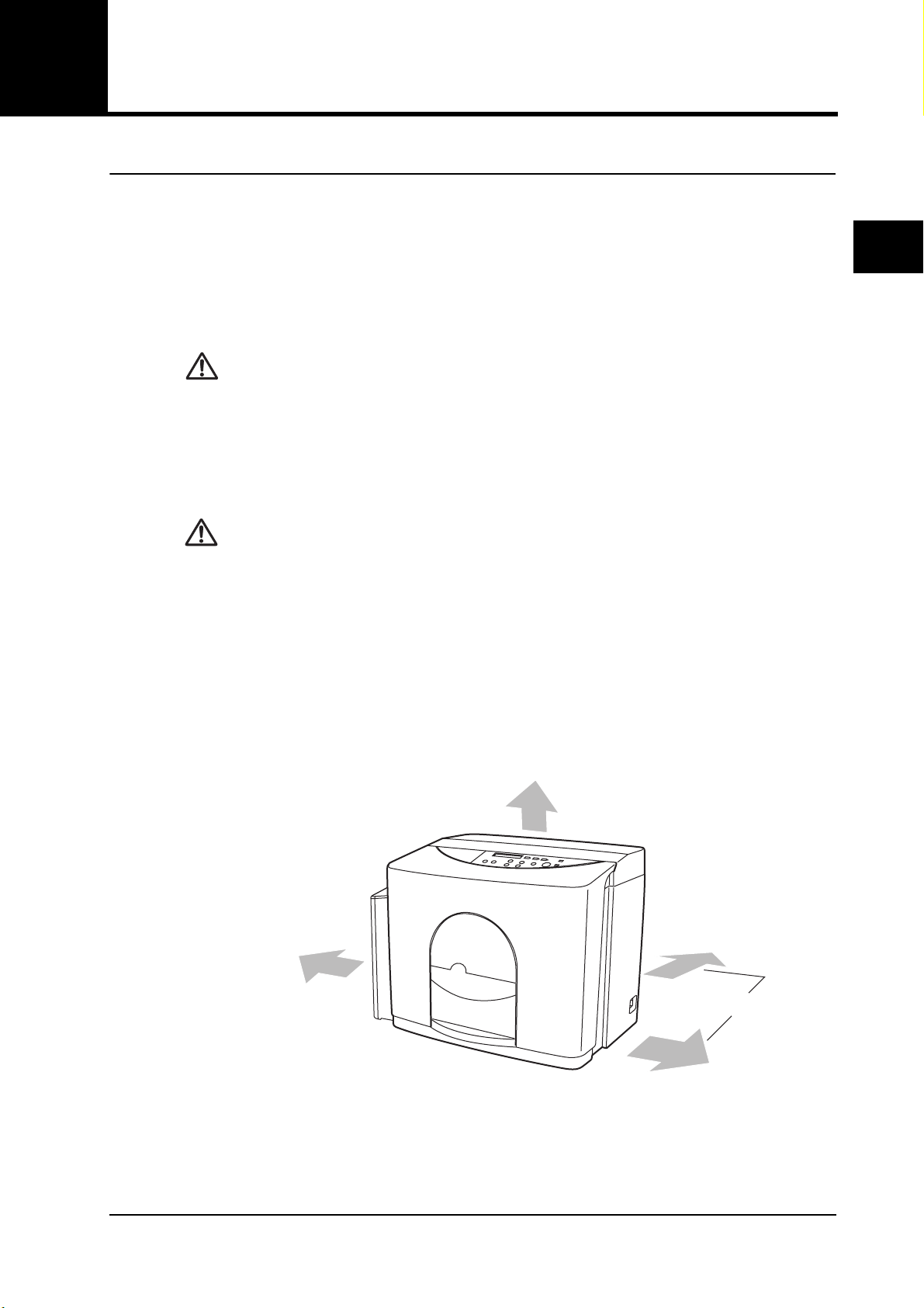
• When relocating the QuickGene-610L, be sure to disconnect the
power plug from the outlet first. Watch your step when you relocate
the QuickGene-610L. If the power cable is damaged, this may cause
a device failure, fire, injury, or electric shock.
• Do not install the QuickGene-610L in an unstable place such as a
slanted surface or a place subject to vibrations. Doing so may cause
injury or device failure.
• Do not install the QuickGene-610L in direct sunlight or close to a
heating device. Doing so may shorten the life of QuickGene-610L, or
cause a failure.
• Two or more people are necessary to relocate the QuickGene-610L.
Otherwise, you may hurt your back or hands because of the weight
of QuickGene-610L (24kg).
5
6
7
• A location that will support the weight of QuickGene-610L (24kg), that is flat and stable, with
no vibration.
• A location away from direct sunlight. Block the sunlight by curtains or blinds as necessary.
• A location which is well-ventilated and not dusty.
• A location where the temperature does not go up and down suddenly.Warming a cold room
suddenly or moving the QuickGene-610L from a room with low temperature to a warm room
may cause condensation inside the device (condensing), and may have a negative influence
on the sample result.
• A location far from water taps, water heaters, humidifiers, air-conditioners and heaters. (Avoid
areas of high temperature and high humidity, or low temperature and low humidity.)
• A location far from objects which generate strong magnetic fields (motors, transformers, TV,
audio speakers, magnets, etc.). Bringing the QuickGene-610L close to any type of magnetic
field may cause a malfunction.
Product Use Limitations
• Fuji Photo Film Co., Ltd. assumes no liability for results regardless of the
intended use.
• It is the user's responsibility to validate the performance of QuickGene kits and
QuickGene-610L for any case of use.
• The QuickGene-610L is a device for research and study only.
When you use the QuickGene-610L, read this manual thoroughly and follow the safety management
regulations of your facilities (laboratory).
x QuickGene-610L User’s Guide Rev. 1.0
Page 13
1
2
3
4
5
QuickGene-610L User’s Guide Rev. 1.0 xi
6
7
Page 14
1
2
3
4
5
6
7
xii QuickGene-610L User’s Guide Rev. 1.0
Page 15

Informations concernant la sécurité
Ce chapitre décrit les précautions de sécurité.
Pour votre sécurité et celle des autres, veuillez suivre les indications et recommandations fournies dans les
pages suivantes et qui concernent l’utilisation du QuickGene-610L.
A propos des instruments
1
WARNING:
CAUTION:
• Si les recommandations suivantes ne sont pas prises en compte, un
incendie ou une décharge électrique peuvent se produire.
- Utilisez un câble d'alimentation conforme aux réglementations de votre pays ou
contactez votre revendeur local.
- Connectez à une prise électrique mise à la terre
- Ne touchez pas la fiche si vous avez les mains mouillées
- N’utilisez pas le QuickGene-610L avec un voltage différent de celui qui est
spécifié sur l’appareil. Ne branchez pas trop appareils sur la prise électrique.
- N’utilisez pas QuickGene-610L si la fiche est endommagée ou si la prise n’est
pas solidement fixée.
- Si les broches de la prise ou de la fiche sont poussiéreuses, nettoyez-les avec
un chiffon sec.
- Lorsque vous retirez la fiche de la prise, faites-le en tenant fermement la prise.
Ne tirez pas le câble.
- Pour tout entretien, débranchez la fiche de la prise murale.
- Ne touchez pas la fiche lorsque le tonnerre gronde.
- Quand le disjoncteur se déclenche, un court circuit peut s’être produit. Ne
démontez pas le QuickGene-610L.
• Ne versez aucun liquide sur le QuickGene-610L. Ne placez aucun
objet contenant du liquide sur l'appareil. Vous risquez, en le faisant,
de provoquer une panne, un incendie ou une décharge électrique.
• En cas de surchauffe de l’appareil, ou s’il dégage de la fumée ou une
odeur bizarre, débranchez immédiatement le câble d’alimentation.
• N’essayez en aucun cas de remodeler ou modifier le QuickGene-610L
sans l'autorisation du fabricant. Cela pourrait entraîner un incendie
ou une décharge électrique.
•
Ne placez – ou ne faites tomber – aucun objet sur le QuickGene-610L.
De même, évitez de lui faire subir des chocs ou des coups, cela pourrait
entraîner des défaillances ou un mauvais fonctionnement de l’appareil.
•
Si un quelconque liquide s’introduit dans l’appareil, épongez-le avec une
serviette en papier, sinon le QuickGene-610L pourrait être endommagé.
• Le capot avant ne tient pas tant qu’il n’a pas atteint sa limite
supérieure d’ouverture. Si vous lâchez le capot avant en l’ouvrant, il
risque de blesser quelqu’un ou d’endommager l’appareil.
•
Lorsque vous remplacez le tuyau de pompe, veillez à porter des gants.
• Au cas où de l’éthanol se renversait, débranchez immédiatement le
câble d’alimentation.
• Des réparations du QuickGene-610L ne doivent être effectuées que par
des agences spécifiquement autorisées par Fuji Photo Films Co., Ltd.
• Et seules doivent être utilisées, les pièces détachées originales
provenant de Fuji Photo Films Co., Ltd.
• Si ce matériel est utilisé de manière non spécifiée par le fabricant, la
protection fournie par le matériel peut s’en trouver diminuée.
2
3
4
5
6
7
QuickGene-610L User’s Guide Rev. 1.0 xiii
Page 16

A propos des conditions d’installation
1
2
3
4
5
6
7
WARNING:
CAUTION:
Pour une utilisation correcte et sûre du QuickGene-610L, installez-le dans un emplacement qui répond aux
conditions suivantes :
• Un emplacement à proximité d’une alimentation électrique. Utilisez une prise C.A.100 ± 10%
à C.A.240V ± 10%, 50Hz ou 60Hz.
• Un emplacement où la température est située entre 15 à 30°C, et ou l’humidité relative est
comprise entre 30 à 80%RH (sans condensation).
• Un emplacement qui peut soutenir le poids du QuickGene-610L (24 kg), qui est plane, stable
et sans vibration.
• Un emplacement éloigné des rayons directs du soleil. Si nécessaire, bloquez le soleil avec
des rideaux ou des stores.
• Un emplacement correctement aéré et sans poussière.
• Un emplacement où la température ne varie pas brutalement. Si vous réchauffez brusquement
une pièce fraîche ou si vous déplacez le QuickGene-610L d’une pièce où la température est
basse à une autre où il fait plus chaud, de la condensation risque de se produire à l’intérieur de
l’appareil et peut avoir une influence adverse sur le résultat de l’échantillon.
• Un emplacement éloigné de robinets d’eau, de bouilloires, d’humidificateurs, d’appareils d’air
conditionné et de chauffage. (Évitez les emplacements à température élevée et forte humidité
ou à basse température et faible humidité).
• Un emplacement éloigné d’objets qui dégagent un champ magnétique fort (moteurs,
transformateurs, TV, haut-parleurs, aimants etc.). Si le QuickGene-610L est à proximité d’un
type quelconque de champ magnétique, il risque d’y avoir un dysfonctionnement.
• N'installez le QuickGene-610L dans un emplacement où il pourrait
être éclaboussé par de l'eau. Cela pourrait entraîner une défaillance
de l’appareil, un incendie ou une décharge électrique.
• Si vous devez déplacer le QuickGene-610L vers un autre
emplacement, veillez à débrancher l’appareil en premier. Faites
attention en déplaçant le QuickGene-610L, si vous marchez sur le
câble d’alimentation et qu’il est endommagé, cela peut entraîner une
défaillance de l’appareil, un incendie ou une décharge électrique.
• N’installez pas le QuickGene-610L sur un emplacement instable,
comme par exemple, une surface inclinée ou sujette à vibrations. Cela
pourrait entraîner des blessures ou un dysfonctionnement.
• Ne placez pas le QuickGene-610L sous l’exposition directe du soleil
ou à proximité d'un appareil de chauffage. Cela pourrait raccourcir la
durée de vie du QuickGene-610L ou provoquer un
dysfonctionnement.
• Pour déplacer le QuickGene-610L, deux personnes au moins sont
nécessaires. Vous risquez, autrement, de vous faire mal au dos ou
aux mains du fait du poids de l’appareil (plus de 20 kg).
Limitations d’utilisation du produit
• Fuji Photo Film Co., Ltd. n’assume aucune responsabilité de résultats quel que soit
l’usage voulu.
• Il est de la responsabilité de l’utilisateur de valider la performance des kits QuickGene
et du QuickGene-610L dans tous les cas d’utilisation.
• Le QuickGene-610L est un appareil uniquement destiné à la recherche et l’étude.
Lors de l’utilisation de QuickGene-610L, lisez d’abord ce manuel entièrement et respectez les règlements
de gestion de risque de votre lieu de travail (laboratoire).
xiv QuickGene-610L User’s Guide Rev. 1.0
Page 17
Sicherheitsinformationen
In diesem Kapitel sind die Sicherheitsmaßregeln beschrieben.
Um Verletzungen zu vermeiden, befolgen Sie bitte die Bedienungsrichtlinien für QuickGene-610L auf den
folgenden Seiten.
Informationen zum Gerät
1
WARNING:
CAUTION:
• Bei Missachtung der folgenden Warnhinweise besteht Brand- und
Stromschlaggefahr.
- Verwenden Sie ein Netzkabel, das den geltenden Bestimmungen Ihres Landes
entspricht, oder wenden Sie sich an Ihren örtlichen Händler.
- Schließen Sie das Netzkabel an eine geerdete Steckdose an.
- Fassen Sie den Netzstecker nicht mit nassen Händen an.
- Betreiben Sie das QuickGene-610L ausschließlich mit der am Gerät
angegebenen Netzspannung. Überlasten Sie die Steckdose nicht durch
Anschließen von zu vielen Geräten.
- Verwenden Sie das QuickGene-610L nicht mit einem beschädigtem Netzstecker
oder einer lockeren Steckdose.
- Wenn die Kontakte des Netzsteckers oder die Steckdose staubig sind, wischen
Sie sie mit einem trockenen Tuch ab.
- Wenn Sie den Netzstecker aus der Steckdose ziehen, fassen Sie stets den
Netzstecker direkt an. Ziehen Sie nicht am Netzkabel.
- Ziehen Sie vor der Durchführung von Wartungsarbeiten den Netzstecker ab.
- Fassen Sie den Netzstecker bei Gewitter nicht an.
- Wenn der Schutzschalter auslöst, kann dies an einem Kurzschluss liegen.
Zerlegen Sie das QuickGene-610L nicht.
•
Verschütten Sie keine Flüssigkeiten über dem QuickGene-610L. Stellen Sie
keine Flüssigkeitsbehälter auf dem QuickGene-610L ab. Dadurch könnte es
zu einem Ausfall des Gerätes, zu einem Brand oder Stromschlag kommen.
• Wenn sich das Gerät überhitzt oder wenn Rauch oder ungewöhnliche
Gerüche auftreten, ziehen Sie sofort das Netzkabel ab.
• Versuchen Sie nicht, das QuickGene-610L ohne die Erlaubnis des
Herstellers zu verändern. Dadurch könnte es zu einem Brand oder
Stromschlag kommen.
•
Legen Sie keine Gegenstände auf dem QuickGene-610L ab, und lassen
Sie keine Gegenstände darauf fallen. Setzen Sie es außerdem keinen
Stößen oder ähnlichen Erschütterungen aus, da es dadurch zu einem
Ausfall oder zu einer Fehlfunktion des QuickGene-610L kommen könnte.
• Wenn im Gerät irgendwelche Flüssigkeiten zurückbleiben, wischen
Sie es mit einem fusselfreien Papiertuch aus. Andernfalls kann es zu
einer Beschädigung des QuickGene-610L kommen.
•
Die vordere Abdeckung rastet nicht vor Erreichen des oberen Anschlags
ein. Wenn Sie die vordere Abdeckung loslassen, während Sie sie öffnen,
kann es zu Verletzungen oder zu einer Beschädigung des Geräts kommen.
• Tragen Sie beim Auswechseln des Pumpenrohrs stets Handschuhe.
•
Falls Ethanol verschüttet werden sollte, ziehen Sie sofort das Netzkabel ab.
•
Reparaturarbeiten am QuickGene-610L sollten nur von Firmen ausgeführt
werden, die von Fuji Photo Films Co., Ltd. ausdrücklich dafür autorisiert sind.
• Dabei sollten nur Original-Ersatzteil von Fuji Photo Films Co., Ltd.
verwendet werden.
• Wenn das Gerät anders als auf die vom Hersteller vorgesehene Weise
verwendet wird, können die Sicherheitseigenschaften des Geräts
beeinträchtigt werden.
2
3
4
5
6
7
QuickGene-610L User’s Guide Rev. 1.0 xv
Page 18
Informationen zur Installation
1
2
3
4
5
6
7
WARNING:
CAUTION:
Für eine problemlose und sichere Verwendung stellen Sie das QuickGene-610L an einem Ort auf, der die
folgenden Bedingungen erfüllt:
• Stromversorgung: Verwenden Sie eine Steckdose mit einer Netzspannung von 100 ± 10% bis
240 V ± 10% AC, 50 Hz oder 60 Hz.
• Temperatur 15 bis 30 °C und relative Luftfeuchtigkeit zwischen 30 und 80 % (nicht kondensierend).
• Eine ebene, stabile Oberfläche, die das Gewicht des QuickGene-610L (24 kg) trägt und die
keinen Vibrationen ausgesetzt ist.
• Kein direktes Sonnenlicht. Falls erforderlich, schützen Sie das Gerät durch Vorhänge oder
Jalousien vor direkter Sonneneinstrahlung.
• Gut belüftete und staubfreie Umgebung.
• Keine abrupten Temperaturschwankungen. Wenn ein kalter Raum schnell aufgeheizt wird
oder das QuickGene-610L aus einem kalten in einen warmen Raum transportiert wird, kann
im Gerät Kondensation auftreten, die das Probenergebnis beeinträchtigen kann.
• Genügend Abstand von Wasserhähnen, Warmwasserbereitern, Luftbefeuchtern,
Klimaanlagen und Heizgeräten. (Vermeiden Sie Bereiche mit hoher Temperatur und hoher
Luftfeuchtigkeit oder niedriger Temperatur und niedriger Luftfeuchtigkeit.)
• Genügend Abstand von Gegenständen, die starke Magnetfelder erzeugen (Elektromotoren,
Transformatoren, Fernsehgeräte, Lautsprecher, Magneten etc.). Wenn das QuickGene-610L
in die Nähe irgendwelcher Magnetfelder gebracht wird, führt dies zu einer Fehlfunktion.
• Stellen Sie das QuickGene-610L nicht an einem Ort auf, an dem es
Spritzwasser ausgesetzt ist. Dadurch könnte es zu einem Ausfall des
Geräts, zu einem Brand oder Stromschlag kommen.
• Wenn Sie den Aufstellungsort des QuickGene-610L ändern, stellen
Sie sicher, dass vorher der Netzstecker gezogen ist. Achten Sie bei
einer Standortveränderung des QuickGene-610L darauf, wohin Sie
treten. Wenn das Netzkabel beschädigt wird, kann es zu einem Ausfall
des Geräts, zu einem Brand oder Stromschlag kommen.
• Stellen Sie das QuickGene-610L nicht auf einem unsicheren Ort auf, z.
B. auf einer abschüssigen Oberfläche oder an einem Ort, der
Vibrationen ausgesetzt ist. Dadurch kann es zu Verletzungen oder
einem Ausfall des Geräts kommen.
• Stellen Sie das QuickGene-610L nicht an einem Ort auf, der direktem
Sonnenlicht ausgesetzt ist oder in der Nähe eines Heizgerätes liegt.
Dadurch könnte die Lebensdauer des QuickGene-610L verkürzt oder
ein Ausfall verursacht werden.
• Eine Veränderung des Aufstellungsorts des QuickGene-610L muss
von mindestens zwei Personen durchgeführt werden. Ansonsten
kann es aufgrund des Gerätegewichts (über 20 kg) zu Verletzungen
des Rückens oder der Hände kommen.
Einschränkungen der Produktverwendung
• Fuji Photo Film Co., Ltd. übernimmt keine Haftung für die Ergebnisse, unabhängig vom
Verwendungszweck.
• Es liegt in der Verantwortung des Anwenders, die Eignung der QuickGene-Kits und
des QuickGene-610L für die jeweils vorgesehene Anwendung zu überprüfen.
• Das QuickGene-610L ist nur für den Einsatz in Forschung und Lehre vorgesehen.
Wenn Sie das QuickGene-610L einsetzen, lesen Sie diese Anleitung sorgfältig durch, und befolgen Sie die
Sicherheitsbestimmungen Ihrer Einrichtung (Labor).
xvi QuickGene-610L User’s Guide Rev. 1.0
Page 19

Contents
1 Installation
1.1 Installation and Use Conditions........................................................ 1
1.2 Checking the QuickGene-610L and Accessories............................. 3
1.3 Remove the Packaging Materials..................................................... 4
1.4 Overview........................................................................................... 5
1.5 Setup Parts....................................................................................... 8
1.6 Checking QuickGene-610L Operation............................................ 18
2 Basic Functions
1
2
2.1 Components ................................................................................... 19
2.2 Working Process of QuickGene-610L ............................................ 20
2.3 Safety Mechanism.......................................................................... 20
2.4 LCD Display Information................................................................. 21
2.5 Main Specifications......................................................................... 22
3 Operation
3.1 Quick Guide.................................................................................... 23
3.2 Turn the Power ON and OFF ......................................................... 24
3.3 Preparation..................................................................................... 25
3.4 Preparation of Lysate (Samples).................................................... 26
3.5 Extraction Operations..................................................................... 27
3.6 When the Front Cover is Opened During PROCESSING. ............. 38
3.7 Operations to Stop Extraction Process........................................... 39
4 Maintenance
4.1 Before Using the QuickGene-610L................................................. 41
4.2 When the QuickGene-610L is left for a Week or More................... 41
4.3 Cleaning the QuickGene-610L ....................................................... 42
4.4 Cleaning the Parts.......................................................................... 43
4.5 How to Replace the Pump Tube..................................................... 43
3
4
5
6
7
5 How to Set Parameters
5.1 Parameters..................................................................................... 47
5.2 How to Set/Change Parameters..................................................... 49
5.3 Parameters in EXPERT Mode........................................................ 51
5.4 Changing Extraction Mode Names................................................. 53
QuickGene-610L User’s Guide Rev. 1.0 xvii
Page 20

2
3
4
1
6 Troubleshooting
6.1 Extraction Failure............................................................................ 55
6.2 Typical Failure ................................................................................55
6.3 Error Messages .............................................................................. 56
6.4 When the Buffer is Contaminated................................................... 57
Appendix A
A.1 Usable Power Supply Cords........................................................... 59
A.2 Options ........................................................................................... 60
A.3 About Services................................................................................61
A.4 Repair Service Period of Product ...................................................61
A.5 Customer Support........................................................................... 61
A.6 Notes for Transfer QuickGene-610L............................................... 62
5
6
7
xviii QuickGene-610L User’s Guide Rev. 1.0
Page 21
INDEX
1 Installation
This chapter explains how to install the QuickGene-610L.
2 Basic Functions
This chapter explains the basic functions of the QuickGene-610L.
3 Operation
This chapter explains the extraction procedures.
4 Maintenance
This chapter describes how to maintain the QuickGene-610L.
5 How to Set Parameters
This chapter explains how to set parameters.
1
2
3
4
5
6 Troubleshooting
This chapter describes the procedures that should be taken when you suspect device failures,
and the messages shown on the LCD.
Appendix A
This appendix describes after-sales services and points to note for transfer.
6
A
QuickGene-610L User’s Guide Rev. 1.0 xix
Page 22

1
2
3
4
5
6
7
xx QuickGene-610L User’s Guide Rev. 1.0
Page 23
1 Installation
:
This chapter explains how to install the QuickGene-610L.
1 Installation
1.1 Installation and Use Conditions
This section explains the installation conditions and operating environment of the QuickGene-610L.
■ Installation conditions
WARNING
CAUTION:
For correct and safe use of QuickGene-610L, install it in a location that meets the following conditions:
•Do not install the QuickGene-610L to a location where it can be
splashed with water.Doing so may cause a device failure, fire, or
electric shock.
•When relocating the QuickGene-610L, be sure to disconnect the power
plug from the outlet first. Watch your step when you relocate the
QuickGene-610L. If the power cable is damaged, this may cause a
device failure, fire, injury, or electric shock.
•Do not install the QuickGene-610L in an unstable place such as a
slanted surface or a place subject to vibrations.Doing so may cause
injury or device failure.
•Do not install the QuickGene-610L in direct sunlight or close to a
heating device.Doing so may shorten the life of QuickGene-610L, or
cause a failure.
•Two or more people are necessary to relocate the QuickGene-610L.
Otherwise, you may hurt your back or hands because of the weight of
QuickGene-610L (24kg).
1
2
3
4
5
• The space shown in the following figure must be allocated.
Top: 30cm
Left: 15cm
from the Bottle Holder Cover)
6
7
Right and Rear: 15cm
QuickGene-610L User’s Guide Rev. 1.0 1
Page 24
2
1 Installation
• A location where power can be provided.Use an AC100±10% to AC240V±10%, 50Hz or 60Hz
outlet.
• A location where the temperature is 15 to 30°C, and humidity is 30 to 80%RH (non condensing).
• A location that will support the weight of QuickGene-610L (24kg), that is flat and stable, with
no vibration.
1
• A location away from direct sunlight.Block the sunlight by curtains or blinds as necessary.
• A location which is well-ventilated and not dusty.
• A location where the temperature does not go up and down suddenly.Warming a cold room
suddenly or moving the QuickGene-610L from a room with low temperature to a warm room
may cause condensation inside the device (condensing), and may have a negative influence
on the sample result.
• A location far from water taps, water heaters, humidifiers, air-conditioners and heaters.
(Avoid areas of high temperature and high humidity, or low temperature and low humidity.)
3
4
5
6
7
• A location far from objects which generate strong magnetic fields (motors, transformers, TV,
audio speakers, magnets, etc.). Bringing the QuickGene-610L close to any type of magnetic
field may cause a malfunction.
■ Use conditions
The following shows the operating environment of the QuickGene-610L.
Items Specifications
Temperature (°C)
Humidity (RH)
Max. wet bulb
temperature (°C)
Temperature gradient (°C/Hr) 12 or less (non condensing)
Humidity gradient (RH/day) 30 or less (non condensing)
Altitude, operating (m) 2000 or lower
Installation (Overvoltage)
Category Definition
Pollution Degree Definition
Pollution Degree Pollution Degree 2. Note: Rated for indoor use only.
During operation
During downtime
During operation
During downtime
During operation 29 (non condensing)
During downtime 29 (non condensing)
15 ~ 30
0 ~ 55
30 ~ 80
10 ~ 80
CAT II Local-level mains (wall sockets). Equipment at this
level includes appliances, portable tools, and similar
products. Equipment is usually cord-connected.
Pollution Degree2
Normally only dry, nonconductive pollution occurs.
Occasionally a temporary conductivity that is caused by
condensation must be expected. This location is a typical
office/home environment.
Temporary condensation occurs only when the product
is out of service.
2 QuickGene-610L User’s Guide Rev. 1.0
Page 25

1.2 Checking the QuickGene-610L and Accessories
Check that the following are included in the package.
Contact your local representative if you notice any missing part(s).
1 Installation
غ QuickGene-610L
غ Bottle Holder غ Collection Tube
غ Bottle Holder Cover
غ QuickGene-610L
User's Guide
غ Holder Carriage
غ Discharge Tray
غ Wash Buffer Pump
Tube (2)
غ Cartridge Holderغ Holder Stand
Holder
غ Elution Buffer
Pump Tube
1
2
3
4
5
غ Elution Buffer Cap (Blue) غ Wash Buffer Cap (Purple)
غ Packing (Spare)
غ Waste Tube (WTL) غ Cartridge (CAL2)
غ Wash Buffer Bottle
(500ml)
6
7
QuickGene-610L User’s Guide Rev. 1.0 3
Page 26
2
3
1 Installation
1.3 Remove the Packaging Materials
After unpacking the QuickGene-610L from the box, do as follows:
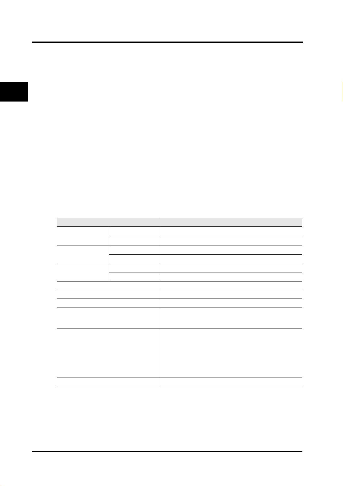
(1) Remove the tape that holds the front cover.
1
Ta pe
(2) Open the front cover, and remove the following items.
4
5
6
7
• Clamps for fixing the carrier both side of the Carrier
• Remove the tape that holds the tubes.
Important: Keep the shipping box and 2 clamps.They will be necessary for
transporting QuickGene-610L.
CAUTION:
Open the front cover as far as it will go, using both hands. The front
cover will not stay open until it is fully opened. If you release the
front cover while opening it, it will drop suddenly and may cause
injury or damage to the device.
Clamps
Ta pe
4 QuickGene-610L User’s Guide Rev. 1.0
Page 27

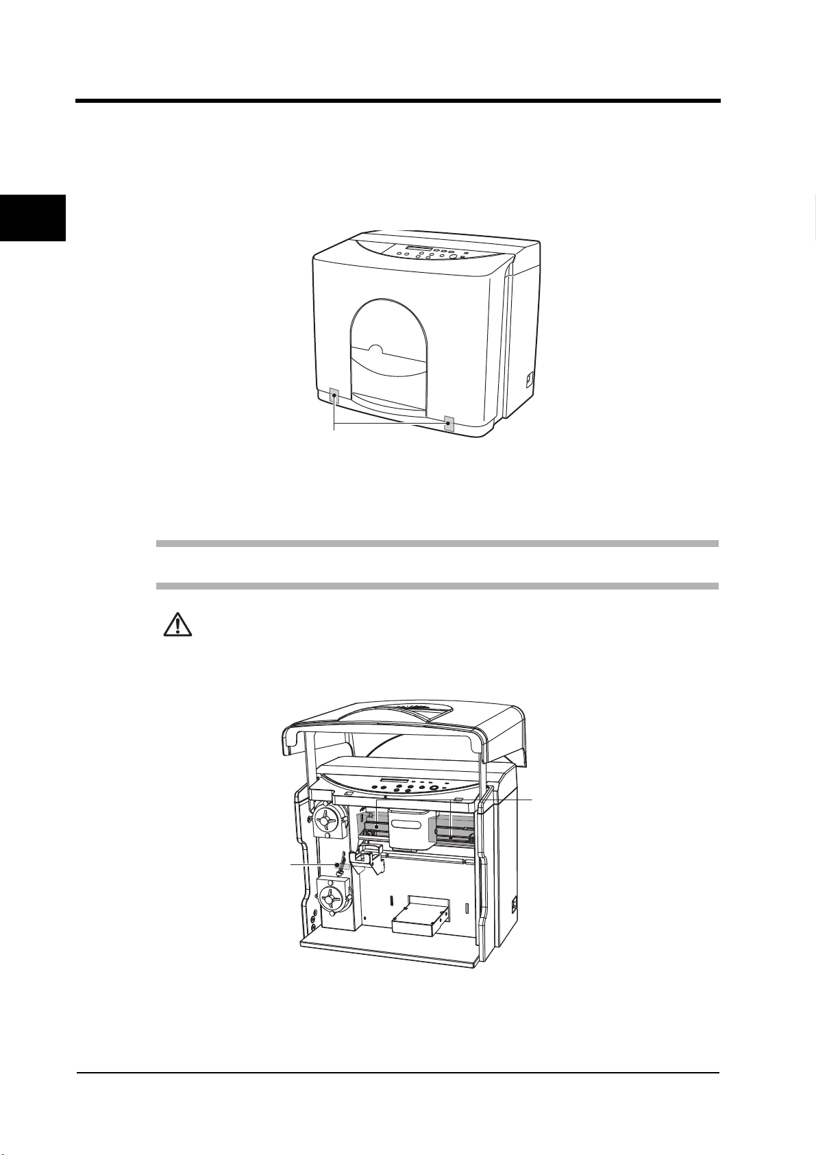
1.4 Overview
This section explains the name and function of each part in the QuickGene-610L.
■ Front and side view
1 Installation
1
Operation Panel
2
Bottle Holder
Cover
Front Cover
3
Handle
■ Rear view
Ventilation Holes
Breaker Checkpoint
Inlet
Power Swtich
4
5
6
7
QuickGene-610L User’s Guide Rev. 1.0 5
Page 28

1 Installation
■ Internal view
2
3
4
5
6
7
1
6 Carrier
1 Wash Buffer
Pump
3 Elution Buffer
2 Bottle Holder 4 Discharge Tray Table
No. Name Function
1 Wash Buffer Pump Sends the wash buffer in the Wash Buffer Bottle to the Carrier.
2 Bottle Holder Set the Wash Buffer Bottle and Elution Buffer Conical Tube.
3 Elution Buffer Pump
4 Discharge Tray Table Set the Discharge Tray to the Discharge Tray Table.
5 Holder Stand
6 Carrier Moves automatically during extraction operation.
7 Pressure Head Presses out the air and uses the pressure to flush out solutions.
8 Elution Buffer Nozzle Puts elution buffer into each cartridge.
9 Wash Buffer Nozzle Puts wash buffer into each cartridge.
10 Sensor
11 Cartridge Holder Set cartridges in the Cartridge Holder.
12 Holder Carriage Set the Waste Tube in the Holder Cartriage.
Collection Tube
13
Holder
Pump
5 Holder Stand
13 Collection Tube Holder
Sends the elution buffer in the Elution Buffer Conical Tube to the
Carrier.
Set the Holder Carriage with the Collection Tube Holder and
Cartridge Holder mounted, to the Holder Stand.
Checks that the carrier is placed in the correct position.
Caution: Do not touch the sensors.
Set Collection Tubes in the Collection Tube Holder.
7 Pressure Head
Elution Buffer Nozzle
8
9
Wash Buffer Nozzle
10 Sensor
11 Cartridge Holder
12 Holder Carriage
6 QuickGene-610L User’s Guide Rev. 1.0
Page 29

■ Operation Panel
1 Installation
BINDING
1
LCD
ً
13
14
ٕ
STOP RESET
8
No. Name Function
1LCD
Lamp (LED)
2POWER
3 READY
4 BINDING
5 WASHING
6ELUTION
Button.
7START
8STOP
9 RESET
9
Displays messages.
For the displayed messages, refer to "2.4 LCD Display Information"(→ page
21) and "6.3 Error Messages"(→ page 56).
The green light is on when the power is on.
The light is off in the following cases.
•When the power is off
•When an abnormality is detected in the power unit
The green light is on when the QuickGene-610L is ready for operation.
The light is off during extraction process or setup.
The green light blinks during binding process or when extraction process is
completed.
The orange light blinks when an error is detected.
The light is off in other cases.
The green light blinks during washing process or when extraction process is
completed.
The orange light blinks when an error is detected.
The light is off in other cases.
The green light blinks during collection process or when the extraction process
is completed.
The orange light blinks when an error is detected.
The light is off in other cases.
Starts a program.
The operation cannot be started while the front cover is open, or if an error has
occurred.
In the setup mode, changed parameters are saved and quit setup mode.
Halts the program of QuickGene-610L.
In the setup mode, changed parameters are not saved and quit setup mode.
Can be used in the following cases to abort the program.
• When pressing the [STOP] button during the extraction process
• When the front cover is opened during extraction process and the process is
paused, and then the front cover is closed
WASHING ELUTION
4
CR MOVE
DISCHARGE
10
5
6
MODE
1112
START
7
POWER
2
READY
3
1
2
3
4
5
6
7
In the setup mode, changed parameters are not saved and quit setup mode.
QuickGene-610L User’s Guide Rev. 1.0 7
Page 30

2
3
4
1
1 Installation
No. Name Function
10 DISCHARGE
11 M ODE
12 CR MOVE
13
14
Discharges the old wash buffer and elution buffer remaining in the tubes.
Discharges the remaining air from the tubes, and fills the tubes with new wash
buffer and elution buffer.
Switch the extraction mode.Each time the button is pressed, the mode is
switched as the following order.
DNA WHOLE BLOOD
ISOLATE A
ISOLATE B
ISOLATE C
ISOLATE D
ISOLATE E
ISOLATE F
Extraction mode names can be changed.
Moves the carrier from side to side.Each time the switch is pressed, the carrier
moves from side to side.
Can be used while the front cover is closed.
Increments the setting value of the item displayed in the LCD at setup mode.
Can only be used at setup mode.
Pressing and simultaneously starts the setup.
Decrements the setting value of the item displayed in the LCD at setup mode.
Can only be used at setup mode.
5
6
7
1.5 Setup Parts
This section explains how to install the parts included in the package.
Install the following parts:
• Power Cable → "
• Pump Tube → "
• Tube → "
• Bottle Holder → "
• Wash Buffer Cap, Elution Buffer Cap, Wash Buffer Bottle (500ml)
■Setup the Wash Buffer Cap and Elution Buffer Cap"(→ page 14)
→ "
• Discharge Tray → "
• Holder Carriage, Holder Stand → "
An empty Wash Buffer Bottle and Elution Buffer Conical Tube are needed to set a Wash Buffer Cap and
Elution Buffer Cap.
Prepare a Wash Buffer Bottle and an Elution Buffer Conical Tube in order to set a Wash Buffer Cap and
an Elution Buffer Cap respectively. One Wash Buffer Bottle (500ml) is included in the package.
The recommended bottles are as follows:
Wash Buffer Bottle (500ml) Nalgenunc 500ml Narrow-Mouth Bottle
Elution Buffer Conical Tube BD Falcon 50ml conical tube
■Setup the power cable"(→ page 9)
■Setup the Pump Tube"(→ page 9)
■Setup the tubes"(→ page 12)
■Setup the Bottle Holder"(→ page 14)
■Setup the Discharge Tray"(→ page 18)
■Setup the Holder Carriage"(→ page 16)
Type Product name
8 QuickGene-610L User’s Guide Rev. 1.0
Page 31

■ Setup the power cable
:
:
The following explains how to install the power cable.
1 Installation
WARNING
Important: Refer to "A.1 Usable Power Supply Cords"(→ page 59)", for details about the
QuickGene-610L (Rear)
Outlet
Power cable
Ignoring the following notations may lead to fire or electric shock.
•Use a power cable that meets your country's standard, or contact your
local distributor.
power cables that can be used in each country.
(1) Connect one of the power plugs of the
power cable to the inlet of QuickGene610L.
(2) Connect the other plug of power cable
to the outlet.
Connect to a grounded
outlet to reach the power
source.
Inlet
WARNING
1
2
3
4
■ Setup the Pump Tube
The following explains how to setup the Pump Tube.
Note: When setting the Pump Tube, wear gloves.
(1) Turn the power on.
Power switch
10
(2) Press the [DISCHARGE] button.
(3) Turn off the power.
Press the [I] side of the switch.
When the QuickGene-610L has been initialized, the
LCD displays "DNA WHOLE BLOOD" (this name
can be changed). It takes about a minute.
Press the [DISCHARGE] button. This operation
makes the drive sockets (→ page 10) of the Wash
Buffer Pump and Elution Buffer Pump rotate to the
position for ease to setup Pump Tubes.
Press the [O] side of the switch.
5
6
7
QuickGene-610L User’s Guide Rev. 1.0 9
Page 32

1 Installation
(4) Open the front cover.
Hold the handle and open the front cover until the
upper limit is reached.
2
3
4
1
Wash Buffer
Pump
Elution
Buffer Pump
CAUTION:
(5) Attach the Pump Tube to the pump.
Attach the Wash Buffer Pump Tube (purple) and
Elution Buffer Pump Tube (transparent) to the Wash
Buffer Pump and the Elution Buffer Pump
respectively.
Important: When attaching the Pump Tube,
The front cover will not
stay on the way to the
upper limit. If you release
the front cover while
opening it, it may cause
injury or device damage.
wear gloves. Do not touch the
drive socket in the pump
without gloves.
After removal of
the pump cover
5
6
7
Drive Socket
(a)Detach the pump cover.
Remove the two screws while holding the
Pump Cover so that it does not fall.
10 QuickGene-610L User’s Guide Rev. 1.0
Page 33

Pump Cover: Rear
r
Rotor
Pump Tube
Pump Tube
Connector
Groove
Slide the Pump Tube
connector into groove
Pump Cover: Front
Notch
Notches face front
1 Installation
(b)Attach the Pump Tube to the rear of the
Pump Cover.
Slide the connectors at the ends of the Pump
Tube into the grooves of the Pump Cover.
Check that the notches on both connectors are
facing the front of the Pump Cover. Slide the
Pump Tube into place inside the Pump Cover
by rotating the rotor.
Adjust the rotor to its original vertical
position.
"WASH" or "ELUTION" is printed on the bag
of the Pump Tubes. Set each type of Pump
Tube correctly.
WASH: for Wash Buffer Pump
ELUTION: for Elution Buffer Pump
Important: Check that both ends of
the Pump Tube are placed
in the grooves.
(c)Attach the Pump Cover.
1
2
3
ࡐࡦࡊࠞࡃⵣ
Drive Head Drive Socket
Rotor
Fit together to attach
Turn the rotor vertical position, then re-attach
the Pump Cover to the retainer, making sure
that the drive head and drive socket are
correctly mated. Secure the Pump Cover in
place with the original 2 screws.
Important: Check the Pump Cover is
fixed well to the Rear.
Then tighten the screws
until the spring washer is
squeezed.
Spring washe
This completes the setup of the Pump Tube. For the
next step, setup the tubes.
4
5
6
7
QuickGene-610L User’s Guide Rev. 1.0 11
Page 34

1
1 Installation
■ Setup the tubes
The following explains how to setup the tubes.
Before setting up the tubes, setup the Pump Tubes.(→ "
Note: When setting the tubes, wear gloves.
■Setup the Pump Tube"(→ page 9))
(1) Connect the tubes to the Pumps.
2
3
4
5
Connect the tube
from the instrument
to the pump
Connect the thick
tube (purple) to
the pump
Connect the thin
tube (blue) to
the pump
(a)Connect the upper tube (from the
instrument) to the Wash Buffer Pump,
and connect the lower tube (from the
instrument) to the Elution Buffer Pump,
by turning as shown in the figure.
(b)Connect the thick tube (upper: purple)
that has the Wash Buffer Cap to the
Wash Buffer Pump, and connect the
thin tube (lower: blue) that has the the
Elution Buffer Cap, by turning as
shown in the figure.
(2) Take off the Wash Buffer Cap and
Elution Buffer Cap from the tubes
connected to the pumps, by turning
Tube Connector.
Note: Hold the cap, and turn the Tube
Connector to disconnect the tube.
6
7
Tube Connector
Wash Buffer Cap
or
Elution Buffer Cap
To avoid contamination, place each
Buffer Cap on cleaned bottle or
tube.
12 QuickGene-610L User’s Guide Rev. 1.0
Page 35

thin tube
thick tube
Close the holes
using the rubber
packing
Inside the instrument
Put the tubes
through the holes.
1 Installation
(3) After removing the caps, remove the
tubes through the holes at the lower
part of the QuickGene-610L.
Remove the thick tube connected to the Wash
Buffer Pump through the lower hole, and remove
the thin tube connected to the Elution Buffer Pump
through the lower hole.
(4) Push in the rubber packing to the holes
from inside the instrument.
1
2
3
4
Clamp position
Side view
Push in
Tube
Groove for
the thin tube
Groove for
the thick tube
Clamp
(5) Hook the tubes with clamps (2 positions).
Push the tubes into the clamps attached to the inside
of the instrument.
Clamps are located 2positions as shown in the
figure.
(6) Put the tubes along the grooves on the
left panel.
Right groove is for the thin tube, Left
groove is for the thick tube.
5
6
7
QuickGene-610L User’s Guide Rev. 1.0 13
Page 36

1 Installation
■ Setup the Bottle Holder
The following explains how to set the Bottle Holder.
(1) Attach the Bottle Holder to the
QuickGene-610L.
2
3
4
1
Set the Bottle Holder at the Roller Catch on the left
panel of the instrument.
Bottle Holder
Roller Catch
(2) Set an empty Wash Buffer Bottle and
Elution Buffer Conical Tube in the Bottle
Holder.
Wash Buffer Bottle
Elution Buffer
Conical Tube
Bottle Holder
■ Setup the Wash Buffer Cap and Elution Buffer Cap
The following explains how to install the Wash Buffer Cap and Elution Buffer Cap.
5
6
7
Wash Buffer
Cap (Purple)
Elution Buffer
Cap (Blue)
(1) Set the Wash Buffer Cap in the Wash
Buffer Bottle, and the Elution Buffer
Conical Cap in the Elution Buffer
Conical Tube.
• Set the purple Wash Buffer Cap on the Wash
Buffer Bottle (Large).
• Set the blue Elution Buffer Cap on the Elution
Buffer Conical Tube (Small).
Note: During buffer bottle replacement,
each tubes can be placed on each
clamps temporarily
Side view
Tubes can
be placed
temporarily
To avoid contamination, do not
touch the end of the tubes.
14 QuickGene-610L User’s Guide Rev. 1.0
Page 37

1 Installation
(2) Connect the Wash Buffer Cap to the
Tube Connector ,thick tube and connect
the Elution Buffer Cap to the Tube
Connect of thin tube, by turning as
shown in the figure.
• Connect the thick tube for the Wash Buffer Pump
(upper, purple) and the purple Wash Buffer Cap.
• Connect the thin tube for the Elution Buffer
Pump (lower, blue) and the blue Elution Buffer
Cap.
Note: Hold the cap, and turn the Tube
Connector to disconnect the tube.
Tube Connector
Wash Buffer Cap
or
Elution Buffer Cap
(3) Set the Bottle Holder Cover.
1
2
3
4
5
Bottle Holder
Cover
QuickGene-610L User’s Guide Rev. 1.0 15
6
7
Page 38

1 Installation
■ Setup the Holder Carriage
The following explains how to install the Holder Carriage.
(1) Attach the Holder Stand to the
QuickGene-610L.
2
3
4
5
1
Cartridge Holder
Holder Stand
Side of the
Cartridge Holder
Put the tab of the
Holder Carriage into
the notch of the
Cartridge Holder.
Holder Carriage
Collection Tube Holder
Insert the tabs of the Holder Stand in the slits on the
QuickGene-610L.
Note: After attaching the Holder Stand,
check that there is no gap between
the bottom of Holder Stand and the
QuickGene-610L.
(2) Set the Collection Tube Holder and
Cartridge Holder in the Holder Carriage.
• To set the Collection Tube Holder, put its left and
right latches into the notches on the Holder
Carriage.
• To set the Cartridge Holder, put the left and right
tabs of the Holder Carriage into the side notches
of the Cartridge Holder.
6
7
Latch
Put the left and right latches
of the Collection Tube Holder
into the Holder Carriage notches.
16 QuickGene-610L User’s Guide Rev. 1.0
Page 39

Side of the Cartridge Holder
The Cartridge Holder
notch is set to
the Holder Carriage tab.
The long
holes can
be seen
1 Installation
(3) Check that the Collection Tube Holder
and Cartridge Holder are correctly set in
the Holder Carriage.
Check the following.
• The left and right long holes at the front of the
Holder Carriage can be seen.
• The left and right tabs of Holder Carriage are set
in the notches on the left and right sides of the
Cartridge Holder.
1
2
3
Holder
Carriage
Set in the
notch
Hook
Long hole
Table prong
Ta bl e
The bottom
front matches
the table front
(4) Attach the Holder Carriage to the
QuickGene-610L.
Hold the handles of the Holder Carriage and attach
the Holder Carriage onto the Holder Stand of the
QuickGene-610L.
Check the following in order to secure the correct
setting.
• The left and right hooks of the Cartridge Holder
are put into the grooves on the shaft of the
QuickGene-610L.
There is a little gap between the hook and the
groove.
Side view of the hook
Gap
Shaft groove
• The bottom front of the Holder Carriage matches
the table front.
• The 2 long holes on the left and right at the front of
the Holder Carriage match the prongs of the Table.
4
5
6
7
Note: When the Carrier is not at the left
end and you cannot attach the
Holder Carriage, close the front
cover and turn on the QuickGene610L. Press the [CR MOVE] button
to move the Carrier to the left end,
and then set the Holder Carriage.
QuickGene-610L User’s Guide Rev. 1.0 17
Page 40

2
1
1 Installation
■ Setup the Discharge Tray
(1) Set the Discharge Tray to the Discharge
Tray Table.
Note: When the Carrier is at the left end
and you cannot set the Discharge
Tray, close the front cover and turn
on the QuickGene-610L. Press the
[CR MOVE] button to move the
Carrier to the right end.
3
4
5
6
7
Discharge Tray
(2) Close the front cover.
1.6 Checking QuickGene-610L Operation
This section explains how to check the operation of QuickGene-610L.
After all the parts are installed, check the operation of QuickGene-610L.
To check the operation, use sterile distilled water instead of buffers and dissolved samples, and perform
the same operation as the normal extraction operation.
For the extraction operation, refer to "3 Operation"(→ page 23).
18 QuickGene-610L User’s Guide Rev. 1.0
Page 41

2 Basic Functions
This chapter explains the basic functions of the QuickGene-610L.
2 Basic Functions
2.1 Components
The following describes the main components of the QuickGene-610L:
1 Operation unit
2 Pump unit
3 Carrier unit
4 Sample unit
5 Buffer setting unit
1
2
3
4
5
No. Component Function
Operate the buttons to select an extraction mode and start/stop an
1 Operation unit
2 Pump unit
3 Carrier unit
4 Sample unit
5 Buffer setting unit
extraction process.
The LCD and LEDs display the device status.
Sends the buffers (wash buffer, elution buffer) to the Carrier unit according
to the extraction program.
Puts pressurized air and buffers (wash buffer, elution buffer) into the
cartridge and performs the extraction process (binding - washing - elution).
By moving the Holder Carriage, the waste liquid and extracted liquid are
discharged into the Waste Tube and Collection Tube, respectively.
The buffers (wash buffer, elution buffer) are set here.The buffers set are
sent to the discharge unit through the pump unit.
6
7
QuickGene-610L User’s Guide Rev. 1.0 19
Page 42

2 Basic Functions
2.2 Working Process of QuickGene-610L
The following describes the working flow of the QuickGene-610L:
(1) The extraction program is started by using the operation unit.
3
4
5
1
2
(2) The wash buffer and elution buffer are sent from the buffer setting unit to the
pump unit.
(3) The wash buffer and elution buffer are sent from the pump unit to the carrier
unit.
(4) The pressurized air, wash buffer, and elution buffer are sent from the carrier
unit into the cartridge (with lysate), and the extraction process is performed.
(5) The extracted sample is eluted to the Collection Tube set in the sample unit.
The waste is discharged to the Waste Tube.
2.3 Safety Mechanism
This section explains the safety mechanisms of the QuickGene-610L.
The QuickGene-610L provides the following safety mechanisms:
• Front cover
• Earth leakage breaker
• LCD, Lamp (LED), and buzzer
6
7
■ Front cover
When the front cover is open, operations such as extraction processes cannot be performed.
Also, if the front cover is opened during the extraction process, it will be temporarily interrupted.
However, when the buffer pump is working, the pump will continue to work until the step is completed.
Operation can be restarted from this point in the process by closing the front cover and pressing the start
button.
Note: During the extraction process, do not open the front cover unless it is necessary.
■ Earth leakage breaker
When there is an electric leak or current surge caused by failures of the QuickGene-610L, the earth
leakage breaker will cut off the power supply.
Check the breaker condition through the Breaker Checkpoint. When the breaker is OK you can see "I". If
the breaker has tripped you will see "O".
If the earth leakage breaker trips, contact your local representative.
■ LCD, Lamp (LED), and buzzer
The LCD, Lamp (LED), and buzzer display the operating status of the QuickGene-610L.
20 QuickGene-610L User’s Guide Rev. 1.0
Page 43

2.4 LCD Display Information
The following describes the messages displayed in the LCD during normal operations.
For the messages displayed in case of errors, refer to "6.3 Error Messages"(→ page 56).
Message Contents
FIRMWARE: VxxLxx Shows the Software version.This appears when you turn on the power.
WAIT A MOMENT Initializing the QuickGene-610L or disposing of the waste.
DNA WHOLE BLOOD
ISOLATE A
ISOLATE B
ISOLATE C
ISOLATE D
ISOLATE E
ISOLATE F
PROCESSING
COMPLETED
START SW → RESTART
1?2?3?4?5?6?
2 Basic Functions
"DNA WHOLE BLOOD" mode is set to operate on the QuickGene-610L.
The operation has not started yet.
"ISOLATE A" mode is set to operate on the QuickGene-610L.
The operation has not started yet.
"ISOLATE B" mode is set to operate on the QuickGene-610L.
The operation has not started yet.
"ISOLATE C" mode is set to operate on the QuickGene-610L.
The operation has not started yet.
"ISOLATE D" mode is set to operate on the QuickGene-610L.
The operation has not started yet.
"ISOLATE E" mode is set to operate on the QuickGene-610L.
The operation has not started yet.
"ISOLATE F" mode is set to operate on the QuickGene-610L.
The operation has not started yet.
Working the extraction program.
Or waiting to shift to wash buffer discharges in the second round
(the waiting time can be set).
The extraction operation is completed.The extraction result will be
displayed after showing this message for one second.
Temporarily stops.This message is displayed in the following cases:
•Temporarily suspended state for the second round wash buffer discharge
•Temporarily suspended state during the multiple times sample processing
•When opening the front cover during the extraction process to interrupt it,
and then closing the cover
•When pressing the [STOP] button during the extraction process
This shows the extraction result.
"?" indicates one of the following marks and meanings:
(check): Successfully extracted
- (hyphen): Extraction failure (Cartridge is clogged)
_ (underscore): No cartridge, or No sample
1
2
3
4
5
6
QuickGene-610L User’s Guide Rev. 1.0 21
7
Page 44

2 Basic Functions
2.5 Main Specifications
The following describes the main specifications of the QuickGene-610L.
■ Main specifications
3
4
5
6
1
2
Items Specifications
Model name QuickGene-610L
Dimensions 448mm (W) x 332mm (D) x 398mm (H)
Weight 24kg
Rated input voltage AC100±10% to AC240V±10%
Power frequency 50/60 Hz
Current consumption 1.0A to 0.5A
Phase Single(with 3P grounding pole)
Range of temperature and
relative humidity
Samples Max. 6 samples can be processed simultaneously
Altitude 2000m or lower (for operation)
Noise Sound pressure: 65db (A-weighted sound pressure level)
Operation panel display LCD 16 characters x 1 line
Sit Indoor use only
Humidity: 30 - 80%RH (non condensing)
Temperature: 15 - 30°C
■ Environmental conditions
EMC FCC Rule Part15b ClassA
EN61326 ClassA
EN61000-3-2
EN61000-3-3
Safety UL61010A-1 CSA C22.2 No.1010
EN61010-1 IEC61010-1
CE LV directive (73/23/EEC)
EMC directive (89/336/EEC)
7
FCC WARNING
Changes or modifications not expressly approved by the party responsible for compliance could void the user’s authority
to operate the equipment.
This equipment has been tested and found to comply with the limits for a Class A digital device pursuant to Part 15 of
the FCC Rules. These limits are designed to provide reasonable protection against harmful interference when the
equipment is operated in a commercial environment. This equipment generates, uses and can radiate radio frequency
energy and, if not installed and used in accordance with the instruction manual, may cause harmful interference to radio
communications. Operation of this equipment in a residential area is likely to cause harmful interference, in which case,
the users will be required to correct the interference at their own expense.
Warning
This is a Class A product of Electromagnetic Interference (EMI) standard. In a domestic environment this product may
cause radio interference in which case the user may be required to take adequate measures.
This Class A digital apparatus complies whith Canadian ICES-003.
Cet appareil mumérique de la class A est comforme à la nomal NMB-003 du Canada.
22 QuickGene-610L User’s Guide Rev. 1.0
Page 45

3 Operation
This chapter explains how to turn the power on and off, and explains the extraction process.
BIOHAZARD
CAUTION:
Important: During the operation, put on appropriate gloves and a mask depending on
the operation.
In the operation from preparing samples to extraction completion, be careful
not to contaminate the samples with sweat, saliva, etc.
3.1 Quick Guide
When performing an extraction operation, check and follow the following:
3 Operation
Wear gloves and a mask during any operation with a Biohazard risk.
1
Do not place any objects containing liquid such as a tray on the
QuickGene-610L.
If the liquid spills, it may damage the operation panel.
2
3
• Execute discharge first
Please execute discharge first.
This operation discharges the old wash buffer, elution buffer, and air remaining in the tubes,
and refills new wash buffer and elution buffer.
After the discharge operation, dispose of the liquid collected in the Discharge Tray.
→ "
■Discharge"(→ page 25)
• Follow the setting order for parts, and set them correctly.
When setting the Collection Tube Holder and Cartridge Holder into the Holder Carriage, follow
the steps below to set them correctly. Failure to do so may cause the sample to spill. For
details, refer to "
■Operations before the start"(→ page 27).
4
5
6
7
QuickGene-610L User’s Guide Rev. 1.0 23
Page 46

3 Operation
:
• Set cartridges, Collection Tubes, and Waste Tubes in the correct positions.
2
4
5
6
1
3
Cartridge
123456
123456
OK
OK
OK
NG
Holder
Holder Carriage
Collection
Tube Holder
3.2 Turn the Power ON and OFF
This section explains how to turn the power of QuickGene-610L on and off.
■ Turning on the power
QuickGene-610L (Rear)
Breaker
checkpoint
Outlet
Inlet
Power cable
Insert the cartridges and tubes starting from the left,
in order.
If they are not in order, a spill of buffer and/or
dissolved sample may occur. This results in an
extraction failure, and buffer and/or dissolved
sample waste.
(1) Check the power cable connection and
the earth leakage breaker.
• Check whether the power cable is connected to
the QuickGene-610L and the outlet.If not,
connect it.
• Check that the earth leakage breaker has not
tripped. When the breaker is OK you can see "I".
If the breaker has tripped you will see "O". If you
see "O", disconnect the power cable and contact
your local representative.
WARNING
•Connect to a grounded
outlet to reach the power
source.
•Do not dismantle the
QuickGene-610L.Doing
so may cause an electric
shock.
7
(2) Press the [I] side of the switch.
Just after the power is turned on, the LCD displays
the software version for a few seconds, then
Power switch
10
changes the display to "WAIT A MOMENT".
LCD displays extraction mode name, when the
initialization has been completed.
■ Turning off the power
(1) Press the [O] side of the switch.
24 QuickGene-610L User’s Guide Rev. 1.0
Page 47

3.3 Preparation
This section explains the preparation of the QuickGene-610L for an extraction process
The following procedures must be performed as preparation of the QuickGene-610L:
• Preparation items
• Discharge
■ Preparation items
Before a test run or extraction operation, perform the following:
• Check all the parts are installed ("1.5 Setup Parts"(→ page 8)).
• Prepare the following:
- Gloves
-Mask
- Wash Buffer Bottle (500ml) *The bottle provided with the kit can also be used.
- Elution Buffer Conical Tube
- 1.5ml micro tube
- Waste Tube (WTL) *provided with the kit
- Cartridge (CAL2) *provided with the kit
- Buffer (wash buffer, elution buffer) *provided with the kit
- Lysate (Samples) (For a test run, use sterile distilled water)
3 Operation
1
2
3
(For a test run, use sterile distilled water)
4
(For the preparation of samples, refer to each kit's handbook.)
Refer to "1.5 Setup Parts"(→ page 8).
■ Discharge
(1) Check the QuickGene-610L has been
cleaned.
For clean up procedure, refer to "■Tasks required
when the device is not used for a week or more"(→
page 41) and "4.4 Cleaning the Parts"(→ page 43).
(2) Turn on the power of QuickGene-610L.
"3.2 Turn the Power ON and OFF"(→ page 24)
(3) Open the front cover.
Take the handle and open the front cover as shown
in the figure.
CAUTION:
The front cover will not
stay on the way to the
upper limit.If you release
the front cover while
opening it, it may cause
injury or device damage.
5
6
7
QuickGene-610L User’s Guide Rev. 1.0 25
Page 48

2
1
3 Operation
Elution
buffer
(4) Check that the Discharge Tray is set on
the Discharge Tray Table.
If it is not set, set it.
■Setup the Discharge Tray"(→ page 18)
"
(5) Put buffer (elution buffer) into a new
Elution Buffer Conical Tube.
The Wash Buffer Bottle provided with the kit can be
used as it is.
Important: Buffer (elution buffer) can be
used for a day in the tube
inside the QuickGene-610L.
4
5
6
7
3
Elution Buffer Concial Tube
Wash Buffer Cap
(Purple)
Elution Buffer
Cap (Blue)
(6) Remove the Bottle Holder Cover, set the
Wash Buffer Bottle and Elution Buffer
Conical Tube (prepared in Step (5)) in
the Bottle Holder, and then put caps on
both.
Note: Do not touch the inner tubes of the
Wash Buffer Cap and Elution
Buffer Cap.
In the case of contamination,
please refer to "6.4 When the
Buffer is Contaminated"(→ page
57).
(7) Set the Bottle Holder Cover.
(8) Close the front cover.
(9) Press the [DISCHARGE] button on the
operation panel.
3.4 Preparation of Lysate (Samples)
Prepare lysate (samples).
Make lysate (samples) using the specified kit for each sample.
For details, refer to the kit's handbook.
26 QuickGene-610L User’s Guide Rev. 1.0
Page 49

3.5 Extraction Operations
This section explains each operation before the start of a program and after the completion of a program.
■ Operations before the start
3 Operation
Important: Perform the extraction operation according to the following procedures.
(1) Open the front cover.
Take the handle and open the front cover as shown
in the figure.
CAUTION:
(2) Take the Holder Carriage out of the
QuickGene-610L.
Grip the handles, lift the Holder Carriage up, and
then take it out.
Note:
(3) Take the Collection Tube Holder and
Cartridge Holder out of the Holder
Carriage.
•When the Carrier is not at the left
end and you cannot remove the
Holder Carriage, close the front
cover and press the [CR MOVE]
button to move the Carrier to the
left end.
•Hold the handles upright and lift
them straight up. Failure to do so
may make work difficult. Lift the
Holder Carriage straight up and
move it forward to remove.
The front cover will not stay
on the way to the upper
limit.If you release the front
cover while opening it, it
may cause injury or device
damage.
1
2
3
4
5
6
7
Cartridge Holder
Holder Carriage
Collection
Tube Holder
QuickGene-610L User’s Guide Rev. 1.0 27
Page 50

2
r
3 Operation
(4) Set the Waste Tubes in the Holder
Carriage.
Put the Waste Tubes into the bottom of the Holder
Carriage.
Waste Tube
1
(5) Open the cover of the Collection Tube
Holder and set the Collection Tubes.
4
5
6
7
3
Collection Tube
Put the cap
into the
groove
Cap
Hold the cover
on both sides
with your fingers,
and rotate the
cover
Close the cover
Put the Collection Tube Cap into the groove of the
Collection Tube Holder to set it.
Cove
Important: Put the Collection Tubes into
the Collection Tube Holder in
the ascending order of the
number printed on the
Collection Tube Holder from "1".
(6) Close the cover of the Collection Tube
Holder.
Collection Tubes are set in the Collection Tube
Holder.
28 QuickGene-610L User’s Guide Rev. 1.0
Page 51

3 Operation
(7) Set the Collection Tube Holder and
Cartridge Holder in the Holder Carriage.
Cartridge Holder
Side of the
Cartridge Holder
Put the tab of the
Holder Carriage into
the notch of the
Cartridge Holder.
Holder Carriage
Collection Tube Holder
Latch
• To set the Collection Tube Holder, put its left and
right latches into the notches on the Holder
Carriage.
• To set the Cartridge Holder, put the left and right
tabs of the Holder Carriage into the side notches
of the Cartridge Holder.
1
2
3
4
Put the left and right latches
of the Collection Tube Holder
into the Holder Carriage notches.
Side of the Cartridge Holder
The Cartridge Holder
notch is set to
the Holder Carriage tab.
5
(8) Check that the Collection Tube Holder
and Cartridge Holder are correctly set in
the Holder Carriage.
Check the following.
6
• The left and right long holes at the front of the
Holder Carriage can be seen.
• The left and right tabs of Holder Carriage are set
in the notches on the left and right sides of the
Cartridge Holder.
7
The long
holes can
be seen
QuickGene-610L User’s Guide Rev. 1.0 29
Page 52

2
r
4
1
3
3 Operation
Fastener Latch
Pull up
Cartridge Holde
(9) Release the lock of the Cartridge Holder
to open the cover.
Release the left and right fasteners on both sides of
the Cartridge Holder and its cover.
(10) Set cartridges in the Cartridge Holder.
Set the cartridges firmly so that they are stable in
the Cartridge Holder.
Important:
•Set cartridges in the ascending
order of the number printed on
the Cartridge Holder from "1".
•When setting cartridges, be
careful that the edge of the
cartridges does not touch the
Cartridge Holder.
5
6
7
123456
123456
OK
OK
OK
Put lysate (samples)
into each cartridge.
NG
Cartridge
Holder
Holder Carriage
Collection
Tube Holder
(11) Check the location of the tubes and
cartridges.
Check that the cartridges, Collection Tubes, and
Waste Tubes are not incorrectly inserted as shown
in the figure.
If they are not in order, the
buffer and/or lysate may
BIOHAZARD
spill, causing a biohazard
risk.
(12) Put lysate (samples) into each
cartridge.
Be careful not to touch the cartridges and the
Cartridge Holder when transferring the lysate
(samples) into the cartridges.
Note: If any lysate is left on the edge of
the cartridge, wipe it with a
Kimwipe® or paper tissue.
30 QuickGene-610L User’s Guide Rev. 1.0
Page 53

Latch the fastene
r
Cartridge Holder
3 Operation
(13) Close the Cartridge Holder Cover and
lock it.
Lock the left and right fasteners on both sides.
1
2
(14) Attach the Holder Carriage to the
QuickGene-610L.
Holder
Carriage
Set in the
notch
Hook
Long hole
Table prong
Ta bl e
The bottom
front matches
the table front
Hold the handles of the Holder Carriage and attach
the Holder Carriage onto the Holder Stand of the
QuickGene-610L.
Check the following in order to secure the correct
setting.
• The left and right hooks of the Cartridge Holder
are put into the grooves on the shaft of the
QuickGene-610L.
(There is a little gap between the hook and the
groove.)
Side view of the hook
Gap
Shaft groove
• The bottom front of the Holder Carriage matches
the table front.
• The 2 long holes on the left and right at the front
of the Holder Carriage match the prongs of the
Table.
Note: When the Carrier is not at the left
end and you cannot attach the
Holder Carriage, close the front
cover and turn on the QuickGene610L. Press the [CR MOVE] button
to move the Carrier to the left end,
and then set the Holder Carriage.
3
4
5
6
7
(15) Close the front cover.
QuickGene-610L User’s Guide Rev. 1.0 31
Page 54

1
3 Operation
(16) Select an extraction mode.
Press the [MODE] button several times until the
target extraction mode appears.
(17) Press the [START] button.
The QuickGene-610L automatically starts the
extraction program.
LCD displays "PROCESSING" during extracting.
Extraction progress can be checked by each lamp
(LED).
2
4
5
6
3
[Display of extraction results]
, , and
are extraction results
Note:
• Do not open the front cover
during the extraction process
(while PROCESSING is
displayed in the LCD). If the
front cover is opened, the
extraction process will be
halted. To continue the process,
refer to "3.6 When the Front
Cover is Opened During
PROCESSING."(→ page 38).
• To quit the process, refer to "3.7
Operations to Stop Extraction
Process"(→ page 39).
• In some extraction modes,
operations are required during
processing. For details, refer to
"
■Optional Operation
Procedure [WASH2
program]"(→ page 33).
(18) Two beeps and all the three lamps
(BINDING, WASHING, ELUTION) blinking
indicates process completion.
The LCD displays the extraction results.
Display Meaning
7
Successfully extracted
Extraction failure (Cartridge is
clogged)
No cartridge, or No sample
21 3456
The numerics are cartridge numbers
Number 1 to 3: Extracted successfully.
Number 4: Extraction failed.
Number 5 to 6: There were no cartridges.
(check)
-
(hyphen)
_
(underscore)
32 QuickGene-610L User’s Guide Rev. 1.0
Page 55

3 Operation
■ Optional Operation Procedure [WASH2 program]
When you chose optional operation mode such as "xxx PLUS" mode (a program added WASH 2 process;
see "5 How to Set Parameters"(→ page 47)), QuickGene-610L pauses after first WASH and LCD displays
"START SW → RESTART". Then the following steps are continued the program.
(1) Open the front cover.
Open the front cover after LCD displays "START
SW → RESTART" with 8 beeps.
1
CAUTION:
(2) Take the Holder Carriage out of the
QuickGene-610L.
Grip the handles, lift the Holder Carriage up, and
then take it out.
Note: Hold the handles upright and lift
them straight up. Failure to do so
may make work difficult. Lift the
Holder Carriage straight up and
move it forward to remove.
The front cover will not
stay on the way to the
upper limit. If you release
the front cover while
opening it, it may cause
injury or device damage.
2
3
4
5
(3) Perform the additional operations.
Dispense a
reagent, etc.
QuickGene-610L User’s Guide Rev. 1.0 33
For example, dispense a reagent into the cartridges.
6
7
Page 56

2
1
3 Operation
Holder
Carriage
Set in the
notch
Hook
(4) Attach the Holder Carriage to the
QuickGene-610L.
Hold the handles of the Holder Carriage and attach
the Holder Carriage onto the Holder Stand of the
QuickGene-610L.
Check the following in order to secure the correct
setting.
• The left and right hooks of the Cartridge Holder
are put into the grooves on the shaft of the
QuickGene-610L.
There is a little gap between the hook and the
groove.
Side view of the hook
Ta bl e
4
5
6
7
3
Long hole
Table prong
■ Operations after the completion
The bottom
front matches
the table front
Gap
Shaft groove
• The bottom front of the Holder Carriage matches
the table front.
• The 2 long holes on the left and right at the front
of the Holder Carriage match the prongs of the
Table.
(5) Close the front cover.
(6) Press the [START] button.
There may be no noise for a while, depending on the
extraction mode or the settings, but the LCD should
show a "PROCESSING".
(1) Open the front cover.
CAUTION:
Open the front cover as far
as it will go, using both
hands. The front cover will
not stay open until it is
fully opened. If you release
the front cover while
opening it, it may cause
injury or damage to the
device.
34 QuickGene-610L User’s Guide Rev. 1.0
Page 57

Press down the tab, and remove
the Collection Tube Holder.
3 Operation
(2) Remove the Collection Tube Holder.
Note: Grip the handle of the Collection
Tube Holder while pressing down
the tab of the cover, and then
remove the Collection Tube Holder.
If the Collection Tube is tilted, the
extracted liquid in it may spill
out.Lift the Collection Tube Holder
upward, and be careful not to tilt it
to pull it out.
1
2
Close the cap
Grip the handles
and remove
(3) Open the Collection Tube Holder Cover
and close the Collection Tube Caps.
Then, take them out.
Note: Check the caps are put on the
tubes completely.
(4) Take the Holder Carriage out of the
QuickGene-610L.
Grip the handles, lift the Holder Carriage up, and
then take it out.
Note:
•When the Carrier is not at the left
end and you cannot remove the
Holder Carriage, close the front
cover and press the [CR MOVE]
button to move the Carrier to the
left end.
•Hold the handles upright and lift
them straight up. Failure to do so
may make work difficult. Lift the
Holder Carriage straight up and
move it forward to remove.
3
4
5
6
7
QuickGene-610L User’s Guide Rev. 1.0 35
Page 58

2
r
1
3 Operation
(5) Remove the Cartridge Holder from the
Holder Carriage, and dispose of the
cartridges.
Release the lock of the Cartridge Holder to open the
cover.
One by one pull out the cartridges and dispose of
them into a waste container.
Note: When taking cartridges out, be
careful so that the edge of the
cartridges does not touch the
Cartridge Holder.
If the edge of the cartridge touches
the Cartridge Holder, wash the
Cartridge Holder.
(6) Take the Waste Tubes out.
4
5
6
7
3
Waste Containe
Dispose of the Waste Tubes according to appropriate
laws and rules.
Dispose of the infectious
wastes according to your
BIOHAZARD
(7) Check whether waste liquid remains in
the Holder Stand and Discharge Tray.
If waste liquid remains in them, dispose of it.
Note: When the Carrier is not at the left
end and you cannot remove the
Discharge Tray, close the front
cover and press the [CR MOVE]
button to move the Carrier to the
right end.
biological safety manuals.
Discharge Tray
Holder Stand
(8) Set the Cartridge Holder and Collection
Tube Holder in the Holder Carriage, and
then install them to the QuickGene610L.
"■Setup the Holder Carriage"(→ page 16)
36 QuickGene-610L User’s Guide Rev. 1.0
Page 59

3 Operation
(9) Close the front cover.
The operation has been completed.
To continue the process, refer to "3.3 Preparation"(→
page 25).
When finishing the operation, perform the following
tasks:
- Turn off the power of QuickGene-610L.
- Dispose of the remaining buffer.
- Clean the dirty parts.
Refer to "4 Maintenance"(→ page 41) for maintenance
details.
Important: After QuickGene-610L operation, if it will not be used again for one week or
more, put 14ml of ethanol in the Wash Buffer Bottle and 7ml of ethanol in the
Elution Buffer Conical Tube, then execute the discharge operation 4 times.
After the discharge operation, if ethanol remains in the tubes, discharge it.
For details, refer to "
or more"(→ page 41).
When the amount of types of kit increases, the contents of wash buffer and
elution buffer will differ from the present kits. For details about the remaining
liquid in the tubes, refer to "6.4 When the Buffer is Contaminated"(→ page 57),
and discharge it.
■Tasks required when the device is not used for a week
1
2
3
4
5
6
7
QuickGene-610L User’s Guide Rev. 1.0 37
Page 60

2
1
3 Operation
3.6 When the Front Cover is Opened During PROCESSING.
When the front cover is opened during processing, the program is halted and the LCD displays "COVER
OPEN". If this occurs while the Wash Buffer Pump or Elution Buffer Pump is running, operation of the
device will not be paused until the process for one cartridge is completed.
After that, the extraction process can be resumed from the operation panel.
To resume the operation after opening the front cover during extraction operation, perform the following
procedures.
To quit the program, refer to "3.7 Operations to Stop Extraction Process"(→ page 39).
Note: When the front cover is opened, do not remove the cartridges or tubes in the
QuickGene-610L. Also, do not move the Pressure Head.
Extraction process restarts from the position where the process was paused.
Operations such as discharge may be performed even without cartridges or
tubes, which may result in liquid spill.
(1) Close the front cover.
4
5
6
7
3
(2) Press the [START] button when "START SW → RESTART" is displayed on the
LCD.
QuickGene-610L will restart from the position where the program is paused.
Restarting operations vary depending on the timing when the front cover is opened (when the operation is
paused).
The following shows the timing when the front cover is opened and the restart operations.
Process status
During
initialization
During binding All operations stop
During washing
During elution
Operations when opening
the front cover
All operations stop
•All operations stop,
except for Wash Buffer
Pump and Elution Buffer
Pump.
•During the wash buffer or
elution buffer discharge
process, the operations
stop after discharge for
one cartridge
Operations at restart
The Pressure Head returns to the original position, then the
operations restart from the paused position.
•The Pressure Head returns to the original position, then
moves to the paused position. Operations restart
beginning with the cartridge that was in operation.
•If the operation is paused while applying pressure, pressure
application is performed again starting with the applicable
cartridge.
If stopped while applying pressure
•The Pressure Head moves to the paused position, and only
pressure application restarts.
•If wash buffer or elution buffer was being discharged,
operations restart with the next cartridge.
If stopped when pressure application was completed or with
no pressure application
•The Pressure Head moves to the next cartridge of the
cartridge being processed, then pressure application and
wash buffer discharge processes restart.
38 QuickGene-610L User’s Guide Rev. 1.0
Page 61

3.7 Operations to Stop Extraction Process
To stop the extraction operation, perform the following procedures:
(1) Press the [STOP] button, or open the front cover.
The LCD displays a message as follows:
If the [STOP] button is pressed: "START SW → RESTART"
If the front cover is opened: "COVER OPEN"
(2) In the case when the front cover is opened, close the front cover.
(3) When the LCD displays "START SW → RESTART", press the [RESET] button
(not the [START] button) to stop the process.
The mid-process extraction results will be displayed on the LCD.
(4) Perform the operation at extraction completion.
"■Optional Operation Procedure [WASH2 program]"(→ page 33)
3 Operation
1
2
3
4
5
6
7
QuickGene-610L User’s Guide Rev. 1.0 39
Page 62

2
3 Operation
1
3
4
5
6
7
40 QuickGene-610L User’s Guide Rev. 1.0
Page 63

4 Maintenance
This chapter describes how to maintain the QuickGene-610L.
When cleaning the QuickGene-610L, wear gloves.
BIOHAZARD
4.1 Before Using the QuickGene-610L
4 Maintenance
1
Before using the QuickGene-610L, perform the following tasks:
• Keep clean inside the instrument and parts.
■Tasks required when the device is not used for a week or more"(→ page 41)
"
• Replace the Wash Buffer Bottle and Elution Buffer Conical Tube.
• Supply/Replace buffers (wash buffer and elution buffer)
The buffers must be used within one day from when they are set in the QuickGene-610L.
• Discharge
Discharge the old wash buffer, elution buffer, and air remaining in the tubes, and refill with the
new wash buffer and elution buffer.
4.2 When the QuickGene-610L is left for a Week or More
Even after completing the operation and turning off the power, there are buffers (wash buffer, elution
buffer) remaining in the QuickGene-610L. When the QuickGene-610L will not be used for a week or
more, the remaining buffers may become crystallized, and cause a clog or damage to the tubes.
Discharge the remaining buffers from the QuickGene-610L and clean the inside with ethanol.
■ Tasks required when the device is not used for a week or more
If the QuickGene-610 will not be used for a week or more after the operation, perform the following
procedures:
(1) Put 14ml of ethanol in the Wash Buffer Bottle and 7ml of ethanol in the Elution
Buffer Conical Tube, then execute the discharge operation.
2
3
4
5
6
For the discharge operation, refer to "■Discharge"(→ page 25).
(2) Repeat the discharge operation 4 times, check the tube is no ethanol
remaining.
(3) Dispose of the waste in the Discharge Tray.
(4) Turn off the power.
■ Tasks required when the QuickGene-610L is used again (after one week or more)
When using the QuickGene-610L again, perform the following procedures:
(1) Put 14ml of sterile distilled water in the Wash Buffer Bottle and 7ml of sterile
distilled water in the Elution Buffer Conical Tube, then execute the discharge
operation.
For the discharge operation, refer to "■Discharge"(→ page 25).
QuickGene-610L User’s Guide Rev. 1.0 41
7
Page 64

4 Maintenance
:
(2) Repeat the discharge operation 4 times, check the tube is no water remaining.
(3) Dispose of the waste in the Discharge Tray.
(4) Perform the extraction operation as usual.
2
3
5
6
1
4
4.3 Cleaning the QuickGene-610L
WARNING
This section explains how to clean the QuickGene-610L.
Note: When cleaning the QuickGene-610L, be sure to wear gloves.
The following describes the parts to clean and cleaning methods:
QuickGene-610L
(outside)
Pressure
Head
Carrier Rail
Note:
Do not clean the
carrier rail.
Before starting the maintenance work, turn off the power of QuickGene610L and disconnect the power plug from the outlet.
Otherwise, it may cause an electric shock.
7
QuickGene-610L
(inside)
Parts to clean Cleaning methods
Pressure Head Wipe with a Kimwipe® or paper tissue soaked with ethanol.
QuickGene-610L
(outside)
QuickGene-610L (inside)
42 QuickGene-610L User’s Guide Rev. 1.0
Remove the dust lightly with a dry, soft cloth.
Wipe with a Kimwipe® or paper tissue soaked with ethanol or 0.5% sodium
hypochlorite solution.
Remove the dust lightly with a dry, soft cloth.
Page 65

4.4 Cleaning the Parts
The following table describes how to clean the parts.
Parts Cleaning methods
Holder Carriage Clean the parts using one of the following methods.
Cartridge Holder
Collection Tube
Holder
Bottle Holder
Holder Stand
Discharge Tray
Wash Buffer Pump Tube
Elution Buffer Pump
Tube
Wash Buffer Cap
Elution Buffer Cap
Holder Cover Remove the dust lightly with a dry, soft cloth.
4 Maintenance
- Clean with neutral detergent, and then wash out with distilled water.
Next, dip into 3% hydrogen peroxide solution at room temperature for 10
minutes.
Lastly, wash the solution out with DEPC water, and dry the parts.
- Soak in a 0.1N sodium hydroxide/0.1% EDTA solution overnight, and
then wash the solution out with DEPC water, and dry the parts.
- Clean with neutral detergent, and then wash out with 0.5% sodium
hypochlorite solution.
Lastly, wash out with distilled water, and dry the parts.
- Perform autoclave sterilization (121°C/20min).
Note that if autoclave sterilization (121°C/20min) is performed for parts
other than metal parts and packing, the parts may be deformed.
After using the QuickGene-610L, dispose of the liquid collected in the
Discharge Tray, and wash the tray with water.
Wipe with a Kimwipe® or paper tissue soaked with ethanol.
Wipe with a Kimwipe® or paper tissue soaked with ethanol.
1
2
3
4
4.5 How to Replace the Pump Tube
This section explains how to replace the Pump Tube.
If the Pump Tube is continuously used without this maintenance, the Pump Tube may break and the buffer
may leak.It is recommended that the Pump Tube be replaced before the required replacement date.
Note: If the QuickGene-610L will not be used for 1 year or more, the Pump Tubes must
be removed from the device.
• Wash Buffer Pump Tube
Replacing the Pump Tube is necessary approximately 3 years after the beginning of
QuickGene-610L use, or before performing 10,000 extraction operations.
• Elution Buffer Pump Tube
The Pump Tube has a life of about 20,000 extraction operations, which is equal to the
instrument life.
Replace the Pump Tube with the spare one included in the package. If all the tubes have been used,
purchase them separately as needed. Note that 20,000 of extraction operations is the instrument life.
When purchasing them, contact the Customer Support.
5
6
7
QuickGene-610L User’s Guide Rev. 1.0 43
Page 66

4 Maintenance
■ How to Replace the Pump Tube
Perform the following procedures to replace the Pump Tube.
2
3
1
4
CAUTION:
When replacing the Pump Tube, wear gloves.
(1) Turn the power on.
Press the [I] side of the switch.
(2) Press the [DISCHARGE] button.
Repeat the discharge operation 4 times, check the
tube is no liquid remaining.
Press the [DISCHARGE] button. This operation
makes the drive sockets of the Wash Buffer Pump
and Elution Buffer Pump rotate to the position for
ease to setup Pump Tubes.
(3) Turn off the power.
Press the [O] side of the switch.
(4) Open the front cover.
Hold the handle and open the front cover until the
upper limit is reached.
CAUTION:
The front cover will not
stay on the way to the
upper limit. If you release
the front cover while
opening it, it may cause
injury or device damage.
5
6
7
(5) Remove the tube connected to the Wash
Buffer Bottle, the tube connected to the
Elution Buffer Conical Tube, and the
tubes connected to the instrument, from
the pumps.
Tubes to the
instrument
Tube from the
Wash Buffer Bottle
Tube from the
Elution Buffer
Conical Tube
(6) Detach the pump cover.
Loosen and remove the screws to detach the pump
cover.
44 QuickGene-610L User’s Guide Rev. 1.0
Page 67

4 Maintenance
(7) Take off the Pump Tube from the pump,
and attach a new Pump Tube to the rear
of the Pump Cover.
Pump Cover: Rear
Rotor
Pump Tube
Pump Tube
Connector
Groove
Slide the Pump Tube
connector into groove
Pump Cover: Front
Notch
Notches face front
■ How to replace the packing
Perform the following procedures to replace the packing.
Slide the connectors at the ends of the Pump Tube
into the grooves of the Pump Cover. Check that the
notches on both connectors are facing the front of
the Pump Cover. Slide the Pump Tube into place
inside the Pump Cover by rotating the rotor.
Adjust the rotor to its original vertical position.
"WASH" or "ELUTION" is printed on the bag of
the Pump Tube. Set each type of Pump Tube
correctly.
WASH: for Wash Buffer Pump
ELUTION: for Elution Buffer Pump
Note: Use the specified Pump Tube.
After this, the procedure is the same as in "How to
install the Pump Tube".Refer to "
Tube"(→ page 9).
■Setup the Pump
(1) Open the front cover.
Hold the handle and open the front cover until the
upper limit is reached.
1
2
3
4
CAUTION:
The front cover will not
stay on the way to the
upper limit. If you release
the front cover while
opening it, it may cause
injury or device damage.
(2) Take the Holder Carriage out of the
QuickGene-610L.
Grip the handles, lift the Holder Carriage up, and
then take it out.
Note:
•When the Carrier is not at the left
end and you cannot remove the
Holder Carriage, close the front
cover and press the [CR MOVE]
button to move the Carrier to the
left end.
•Hold the handles upright and lift
them straight up. Failure to do so
may make work difficult. Lift the
Holder Carriage straight up and
move it forward to remove.
5
6
7
QuickGene-610L User’s Guide Rev. 1.0 45
Page 68

2
r
4 Maintenance
(3) Release the lock of the Cartridge Holder
to open the cover. Then raise the tabs of
the packing and lift it up.
Raise the tabs of the packing and lift it up.
1
3
5
6
7
4
Squeeze
the latches
Ta bs
Latch the fastene
(4) Gently squeeze the new packing into the
eight latches on the Cartridge Holder
Cover to set it.
Make the packing tabs face up (when the cover is
open).
(5) Close the Cartridge Holder Cover and
lock it.
Fasten the left and right fasteners on both sides to
lock the Cartridge Holder Cover.
Cartridge Holder
46 QuickGene-610L User’s Guide Rev. 1.0
(6) Attach the Holder Carriage to the
QuickGene-610L.
(7) Close the front cover.
Page 69

5 How to Set Parameters
This chapter explains how to set parameters.
"Set Parameters" means to change the values (such as buffer volume, number of discharges, etc.) for each
extraction mode.
The parameters set in the QuickGene-610L are stored in 7 separate memory areas.
The name of each extraction mode can be selected from 35 names.
Therefore, even if an extraction mode name is changed, the parameter values will not be changed.
• → "5.2 How to Set/Change Parameters"(→ page 49)
• → "5.4 Changing Extraction Mode Names"(→ page 53)
5 How to Set Parameters
1
Important:
5.1 Parameters
Settings of each parameter can be changed from the setup mode.
Some parameters are changed from the normal setup mode (USER mode) and others are changed from the
EXPERT mode.
The following table shows the display sequence, setting range, default value, etc. for each parameter in
USER mode.
Display
sequenceLCD message
1 BIND PEAK
2 WASH COUNT
3 WASH PEAK
4 WASH VOL1
5 WASH VOL2
6 WASH VOL3
7 WASH VOL4
8 WASH VOL5
9 WASH DIP TM
10 WAS2 WAIT T
11 WAS2 COUNT
12 WAS2 PEAK
13 WAS2 VOL1
14 WAS2 VOL2
15 WAS2 VOL3
16 WAS2 VOL4
17 WAS2 VOL5
18 ELUT VOL
19 ELUT PEAK
20 ELUT DIP TM
• The setup is used to change the parameters, according to new protocol of
the kit, etc.Please check the parameters for each kit's handbook.
• In the case of wrong value for parameters, it will cause buffer spill or sample
extraction failure.It is the user's responsibility to change the parameters.
In EXPERT mode, there are some crucial parameters. Therefore, you must
not change any parameters in EXPERT mode without our guidance.
Mode name (The value displays the default)
Setting
range
30 ~ 160
0 ~ 5
30 ~ 160
0 ~ 7500
0 ~ 7500
0 ~ 7500
0 ~ 7500
0 ~ 7500
0 ~ 510
0 ~ 255
0 ~ 5
30 ~ 160
0 ~ 7500
0 ~ 7500
0 ~ 7500
0 ~ 7500
0 ~ 7500
50 ~ 500
30 ~ 160
0 ~ 510
Unit
kpa 120 120 120 120 120 120 120
time(s)3333333
kpa 90909090909090
µl 7500 7500 7500 7500 7500 7500 7500
µl 6500 6500 6500 6500 6500 6500 6500
µl 5500 5500 5500 5500 5500 5500 5500
µl 0000000
µl 0000000
sec 0000000
min 0000000
time(s)0000000
kpa 90909090909090
µl 7500 7500 7500 7500 7500 7500 7500
µl 6500 6500 6500 6500 6500 6500 6500
µl 5500 5500 5500 5500 5500 5500 5500
µl 0000000
µl 0000000
µl 500 500 500 500 500 500 500
kpa 100 100 100 100 100 100 100
sec 0000000
DNA
WHOLE
BLOOD
ISOLATE AISOLATE BISOLATE CISOLATE DISOLATE EISOLATE
F
2
3
4
5
6
7
QuickGene-610L User’s Guide Rev. 1.0 47
Page 70

2
3
4
6
7
1
5
5 How to Set Parameters
The following table shows the meaning of each parameter.
Di
spl
ay
se
qu
en
ce
1
2
3
4
5
6
7
8
9
10
LCD message Parameter name Meaning
BIND PEAK: 30
- BIND PEAK: 160
WASH COUNT: 0
- WASH COUNT: 5
WASH PEAK: 30
- WASH PEAK: 160
WASH VOL1: 0
- WASH VOL1: 7500
WASH VOL2: 0
- WASH VOL2: 7500
WASH VOL3: 0
- WASH VOL3: 7500
WASH VOL4: 0
- WASH VOL4: 7500
WASH VOL5: 0
- WASH VOL5: 7500
WASH DIP TM: 0
- WASH DIP TM:510
WAS2 WAIT T: 0
- WAS2 WAIT T:255
Peak pressure on the
sample
Frequency of wash
buffer discharges
Wash buffer peak
pressure
1st wash buffer
discharge rate
2nd wash buffer
discharge rate
3rd wash buffer
discharge rate
4th wash buffer
discharge rate
5th wash buffer
discharge rate
Wash buffer immersion
management timer
Waiting time
Sets the peak pressure during pressure
application.Judgment criteria is "the pressure before
pressure application + the pressure set in this item".
Pressure application may be stopped before reaching the
peak pressure, if air pressure drops suddenly, indicating that
all liquid has been discharged.
Can be specified between 30 - 160 kpa in increments of
1kpa.
Set frequency of wash buffer discharges
Can be specified between 0 - 5 times.
Sets the peak pressure during pressure application.
Judgment criteria is "the pressure before pressure
application + the pressure set in this item". Pressure
application may be stopped before reaching the peak
pressure, if air pressure drops suddenly, indicating that all
liquid has been discharged.
Can be specified between 30 - 160 kpa in increments of
1kpa.
Sets the first wash buffer discharge rate.
Can be specified between 0 - 7500µl in increments of 250µl.
When 0µl is specified, although the Carrier moves to the
wash buffer discharge position, it does not discharge the
wash buffer.
Sets the second wash buffer discharge rate.
Can be specified between 0 - 7500µl in increments of 250µl.
When 0µl is specified, although the Carrier moves to the
wash buffer discharge position, it does not discharge the
wash buffer.
Sets the third wash buffer discharge rate.
Can be specified between 0 - 7500µl in increments of 250µl.
When 0µl is specified, although the Carrier moves to the
wash buffer discharge position, it does not discharge the
wash buffer.
Sets the fourth wash buffer discharge rate.
Can be specified between 0 - 7500µl in increments of 250µl.
When 0µl is specified, although the Carrier moves to the
wash buffer discharge position, it does not discharge the
wash buffer.
Sets the fifth wash buffer discharge rate.
Can be specified between 0 - 7500µl in increments of 250µl.
When 0µl is specified, although the Carrier moves to the
wash buffer discharge position, it does not discharge the
wash buffer.
Sets the wash buffer immersion management time.
Can be specified between 0 - 510 sec. in increments of 2
seconds.
Sets the time to wait for shifting to wash buffer discharges in
the second round.
Can be specified between 0 - 255 min. in increments of 1
minute.
48 QuickGene-610L User’s Guide Rev. 1.0
Page 71

Di
spl
ay
se
qu
en
ce
11
12
13
14
15
16
17
18
19
20
LCD message Parameter name Meaning
WAS2 COUNT: 0
- WAS2 COUNT: 5
WAS2 PEAK: 30
- WAS2 PEAK: 160
WAS2 VOL1: 0
- WAS2 VOL1: 7500
WAS2 VOL2: 0
- WAS2 VOL2: 7500
WAS2 VOL3: 0
- WAS2 VOL3: 7500
WAS2 VOL4: 0
- WAS2 VOL4: 7500
WAS2 VOL5: 0
- WAS2 VOL5: 7500
ELUT VOL: 50
- ELUT VOL: 500
ELUT PEAK: 30
- ELUT PEAK: 160
ELUT DIP TM: 0
- ELUT DIP TM:510
Frequency of wash
buffer discharges in the
2nd round
Wash buffer peak
pressure in the 2nd
round
1st Wash Buffer
Discharge Rate in the
2nd round
2nd WBDR in the 2nd
round
3rd WBDR in the 2nd
round
4th WBDR in the 2nd
round
5th WBDR in the 2nd
round
Elution buffer discharge
rate
Elution buffer peak
pressure
Elution buffer immersion
management timer
5 How to Set Parameters
Sets the frequency of wash buffer discharges in the second
round.
Can be specified between 0 - 5 times.
Sets the peak pressure during pressure
application.Judgment criteria is "the pressure before
pressure application + the pressure set in this item".
Pressure application may be stopped before reaching the
peak pressure, if air pressure drops suddenly, indicating that
all liquid has been discharged.
Can be specified between 30 - 160 kpa in increments of
1kpa.
Sets the first wash buffer discharge rate in the second round.
Can be specified between 0 - 7500µl in increments of 250µl.
Sets the second wash buffer discharge rate in the second
round.
Can be specified between 0 - 7500µl in increments of 250µl.
Sets the third wash buffer discharge rate in the second
round.
Can be specified between 0 - 7500µl in increments of 250µl.
Sets the fourth wash buffer discharge rate in the second
round.
Can be specified between 0 - 7500µl in increments of 250µl.
Sets the fifth wash buffer discharge rate in the second round.
Can be specified between 0 - 7500µl in increments of 250µl.
Sets the elution buffer discharge rate.
Can be specified between 50 - 500µl in increments of 50µl.
Sets the peak pressure during pressure
application.Judgment criteria is "the pressure before
pressure application + the pressure set in this item".
Pressure application may be stopped before reaching the
peak pressure, if air pressure drops suddenly, indicating that
all liquid has been discharged.
Can be specified between 30 - 160 kpa in increments of
1kpa.
Sets the elution buffer immersion management time.
Can be specified between 0 - 510 sec. in increments of 2
seconds.
1
2
3
4
5
6
7
5.2 How to Set/Change Parameters
Settings of each parameter can be changed from the setup mode.
■ How to change Parameters
The following explains how to change settings of each parameter.
(1) Select the extraction mode.
Press the [MODE] button several times until the
target extraction mode appears.
QuickGene-610L User’s Guide Rev. 1.0 49
Page 72

5 How to Set Parameters
[Example of messages dispalyed in
operation panel]
(2) Press the [ ] [ ] buttons
simultaneously.
When the LCD displays as shown in the figure, the
setup mode starts.
2
3
4
1
5
SETUP START
DNA WHOLE BLOOD
The present mode is displayed
BIND PEAK : 120 *
- * is the value saved in the memory
(3) Press the [MODE] button several times
until the target parameter appears.
To return to the previous parameter, press the
[DISCHARGE] button.
(4) Change the parameter settings using
the [ ] [ ] buttons.
- [ ] switch: raises the setting value.
- [ ] switch: lowers the setting value.
- Holding one of the above switches down can
change the setting values consecutively.
When changing other items, repeat steps (3) and (4).
6
7
[Display on operation panel]
SETUP WRITING
(Save the settings)
SETUP COMPLETED
DNA WHOLE BLOOD
Exit setup mode and display current
extraction mode
(5) Press the [START] button then save the
changed parameters.
The saved parameters are written into non-volatile
memory. The data will not be lost even if the power
is turned off.
When the LCD displays as shown in the figure at
the left, the changed settings are saved and the setup
mode ends.
Important: To cancel the saving
parameters, press the [STOP] or
[RESET] button.
The setup mode ends without
saving the changed parameters.
50 QuickGene-610L User’s Guide Rev. 1.0
Page 73

5.3 Parameters in EXPERT Mode
In EXPERT mode, in addition to the USER mode parameters values of special parameters can also be
changed.
Note: In EXPERT mode, there are some crucial parameters. Therefore, you must not
change any parameters in EXPERT mode without our guidance.
The following table shows the display sequence, setting range, default value, etc. for each parameter in
EXPERT mode.
5 How to Set Parameters
1
Dis
pla
y
se
LCD message
qu
en
ce
1 BIND COUNT
2 BIND SPEED
3 BIND PEAK
4 BIND UP TM
5 BIND RETRY
6 BIND LOWER
7 BIND DOWN T
8 BIND R DN T
9 BIND FALL
10 WASH COUNT
11 WASH SPEED
12 WASH PEAK
13 WASH UP TM
14 WASH RETRY
15 WASH LOWER
16 WASH DOWN T
17 WASH R DN T
18 WASH FALL
19 WASH VOL1
20 WASH VOL2
21 WASH VOL3
22 WASH VOL4
23 WASH VOL5
24 WASH DIP TM
25 WAS2 WAIT T
26 WAS2 COUNT
27 WAS2 SPEED
28 WAS2 PEAK
29 WAS2 UP TM
30 WAS2 RETRY
31 WAS2 LOWER
32 WAS2 DOWN T
33 WAS2 R DN T
Setting
range
1 ~ 5
1 ~ 12
30 ~ 160
6 ~ 50
30 ~ 160
3 ~ 160
2 ~ 510
2 ~ 510
5 ~ 60
0 ~ 5
1 ~ 12
30 ~ 160
1 ~ 50
30 ~ 160
3 ~ 160
2 ~ 510
2 ~ 510
5 ~ 60
0 ~ 7500
0 ~ 7500
0 ~ 7500
0 ~ 7500
0 ~ 7500
0 ~ 510
0 ~ 255
0 ~ 5
1 ~ 12
30 ~ 160
1 ~ 50
30 ~ 160
3 ~ 160
2 ~ 510
2 ~ 510
Mode name (The value displays the default)
DNA
WHOLE
Unit
BLOOD
time(s)1111 111
- 12121212 121212
kpa 120 120 120 120 120 120 120
sec 15151515 151515
kpa 160 160 160 160 160 160 160
kpa 90909090 909090
sec 26262626 262626
sec 100 100 100 100 100 100 100
kpa 60606060 606060
time(s)3333 333
- 12121212 121212
kpa 90909090 909090
sec 15151515 151515
kpa 90909090 909090
kpa 80808080 808080
sec 20202020 202020
sec 100 100 100 100 100 100 100
kpa 40404040 404040
µl 7500 7500 7500 7500 7500 7500 7500
µl 6500 6500 6500 6500 6500 6500 6500
µl 5500 5500 5500 5500 5500 5500 5500
µl 0000000
µl 0000000
sec 0000 000
min 0000 000
time(s)0000 000
- 12121212 121212
kpa 90909090 909090
sec 15151515 151515
kpa 90909090 909090
kpa 80808080 808080
sec 20202020 202020
sec 100 100 100 100 100 100 100
ISOLATE AISOLATE BISOLATE CISOLATE DISOLATE EISOLATE
F
2
3
4
5
6
7
QuickGene-610L User’s Guide Rev. 1.0 51
Page 74
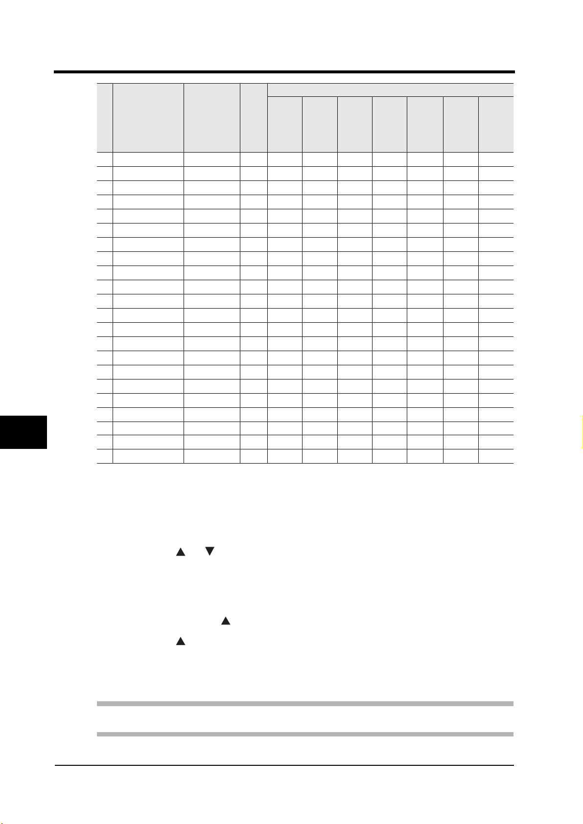
5 How to Set Parameters
2
3
4
1
5
Dis
pla
y
se
LCD message
qu
en
ce
34 WAS2 FALL
35 WAS2 VOL1
36 WAS2 VOL2
37 WAS2 VOL3
38 WAS2 VOL4
39 WAS2 VOL5
40 ELUT VOL
41 ELUT COUNT
42 ELUT SPEED
43 ELUT PEAK
44 ELUT UP TM
45 ELUT RETRY
46 ELUT LOWER
47 ELUT DOWN T
48 ELUT R DN T
49 ELUT FALL
50 ELUT DIP TM
51 W DSVOL S
52 E DSVOL S
53 BUZZER ON or OFF - ON ON ON ON ON ON ON
54 DETECT PRES
55 DOWN PRES
Setting
range
5 ~ 60
0 ~ 7500
0 ~ 7500
0 ~ 7500
0 ~ 7500
0 ~ 7500
50 ~ 500
0 ~ 5
1 ~ 12
30 ~ 160
1 ~ 255
30 ~ 160
3 ~ 160
2 ~ 510
2 ~ 510
5 ~ 60
0 ~ 510
5000 ~ 15000
2200 ~ 6000
1 ~ 50
10 ~ 50
Unit
kpa 40404040 404040
µl 7500 7500 7500 7500 7500 7500 7500
µl 6500 6500 6500 6500 6500 6500 6500
µl 5500 5500 5500 5500 5500 5500 5500
µl 0000000
µl 0000000
µl 500 500 500 500 500 500 500
time(s)1111 111
- 12121212 121212
kpa 100 100 100 100 100 100 100
sec 15151515 151515
kpa 100 100 100 100 100 100 100
kpa 65656565 656565
sec 20202020 202020
sec 30303030 303030
kpa 40404040 404040
sec 0000 000
µl 5000 5000 5000 5000 5000 5000 5000
µl 2200 2200 2200 2200 2200 2200 2200
kpa 15151515 151515
kpa 50505050 505050
DNA
WHOLE
BLOOD
Mode name (The value displays the default)
ISOLATE AISOLATE BISOLATE CISOLATE DISOLATE EISOLATE
F
6
7
■ EXPERT mode
The following explains how to shift to the EXPERT mode.
(1) Select the extraction mode whose parameter is to be changed.
Press the [MODE] button several times until the target extraction mode appears.
(2) Press the [ ] [ ] buttons simultaneously.
Setup mode starts.
(3) Press the [MODE] or [DISCHARGE] button several times until the following
message is displayed on the LCD:
"EXPERT MODE? Y → "
(4) Press the [ ] button.
Change the mode to the EXPERT mode.
Settings of parameters in EXPERT mode can be changed with the same procedures as in the normal setup
mode. For details, refer to "
Note: In EXPERT mode, there are some crucial parameters. Therefore, you must not
change any parameters in EXPERT mode without our guidance.
■ How to change Parameters"(→ page 49).
52 QuickGene-610L User’s Guide Rev. 1.0
Page 75

5.4 Changing Extraction Mode Names
Extraction mode names displayed on the LCD can be changed.
Renaming is performed in RENAME mode.
Important: In RENAME mode, only extraction mode names are changed without changing
parameter values of the corresponding modes.
The following names can be used for extraction mode name change:
5 How to Set Parameters
1
Display
sequence
1 DNA WHOLE BLOOD (Default) 19 DNA PLANT
2 ISOLATE A (Default) 20 RNA PLANT
3 ISOLATE B (Default) 21 DNA VIRUS
4 ISOLATE C (Default) 22 RNA VIRUS
5 ISOLATE D (Default) 23 SWAB
6 ISOLATE E (Default) 24 STOOL
7 ISOLATE F (Default) 25 PCR PURIFY
8 ISOLATE G 26 GEL EXTRACTION
9 ISOLATE H 27 REACTION CLEANUP
10 RNA WHOLE BLOOD 28 DYE CLEANUP
11 RNA BLOOD PLUS 29 RNA BACTERIA
12 RNA CELL 30 DNA BACTERIA
13 RNA CELL PLUS 31 BACTERIA PLUS
14 DNA TISSUE 32 DNA YEAST
15 RNA TISSUE 33 DNA CULTURE CELL
16 RNA TISSUE PLUS 34 DNA HAIR/NAIL
17 PLASMID 35 DNA BUFFYCOAT
18 PLASMID B
Extraction mode name
Display
sequence
Extraction mode name
2
3
4
5
■ How to change extraction mode names
The following explains how to change extraction mode names.
(1) Select the extraction mode whose
parameter is to be changed.
Press the [MODE] button several times until the
target extraction mode appears on the LCD.
(2) Press the [ ] [ ] buttons
simultaneously.
Setup mode starts.
(3) Press the [MODE] or [DISCHARGE]
button several times until the following
message is displayed on the LCD:
"RENAME MODE? Y → "
(4) Press the [ ] button.
RENAME mode starts.
QuickGene-610L User’s Guide Rev. 1.0 53
6
7
Page 76

5 How to Set Parameters
(5) Press the [MODE] or [DISCHARGE]
button several times until the extraction
mode name to be applied is displayed
on the LCD.
(6) Press the [START] button when the
1
[Display on operation panel]
DNA WHOLE BLOOD
mode name to be applied is displayed
on the LCD.
After the name before being changed is displayed
on the LCD, a message to ask whether to save the
new name is displayed.
2
3
4
6
5
(Extraction mode name before change)
RENAME? Y N
Ask whether to save the new name or not
[Display on operation panel]
NAME WRITING
(Save the new name)
RENAME COMPLETED
RENAME MODE? Y
Exit RENAME mode and change
to USER mode
(7) Press the [ ] button and save the new
name.
When the LCD displays as shown in the figure on
the left, the changed name is saved and the mode
returns to the USER mode.
Important:
• When not saving the new
name, press the [ ] button.
The LCD display changes to
the "RENAME MODE? Y → "
without saving the new name.
• To cancel the new name,
press the [STOP] or [RESET]
button.
The setup mode ends without
saving the new name, and the
current extraction mode will
be displayed.
7
54 QuickGene-610L User’s Guide Rev. 1.0
Page 77

6 Troubleshooting
This chapter describes the procedures that should be taken when you suspect device failures, and error
messages shown on the LCD.
6 Troubleshooting
6.1 Extraction Failure
If samples cannot be extracted successfully, check the parameter settings.
If an inappropriate parameter value has been set, it will cause a buffer spill or sample extraction error.Be
careful when changing the values. When changing parameters, follow the instructions of the kit's
handbook.
For details of parameter setting, refer to "5 How to Set Parameters"(→ page 47).
If the problems cannot be solved, contact your local representative.
6.2 Typical Failure
Check the following items before contacting your local representative.
Phenomenon Cause Appropriate action
The QuickGene-610L does
not start after turning on the
power.
The circuit breaker tripped.
The extraction has stopped
in the middle of the
operation.
The extraction work has
stopped because the wash
buffer and elution buffer will
not flow through the nozzle.
The preprocessed sample
that has been dispensed in
the cartridge does not
steadily drop into the
Collection Tube and the
Waste Tube.
The QuickGene-610L emits
an abnormal noise.
The QuickGene-610L emits
an abnormal smell.
Is the power plug
connected to the outlet?
There may be a current
surge or electric leak
caused by failure of the
QuickGene-610L.
•Did you open the front
cover during the
operation?
•It sometimes stops for time
adjustment during
extraction work.
Did you perform the
discharge operation?
Is the cartridge inserted
correctly into the Cartridge
Holder?
The position of Collection
Tube Holder table may be
located in wrong place.
A failure may be suspected.
Connect the power plug to the outlet
completely.
Contact your local representative.
During extraction work (While the
operation panel displays "PROCESSING"),
do not open the front cover.
If you opened the front cover during the
operation and it stopped the extraction work,
refer to "3.6 When the Front Cover is
Opened During PROCESSING."(→ page
38).
Do not forget to press the [DISCHARGE]
button after putting the wash buffer and
elution buffer into the bottle and conical
tube.
•Insert the cartridges completely into the
Cartridge Holder.
•Set the Collection Tube and the Waste
Tube corresponding to the cartridge
inserting point.
Contact your local representative.
Contact your local representative.
Turn off the power at once, and remove the
power cable from the outlet. Then, contact
your local representative.
1
2
3
4
5
6
7
QuickGene-610L User’s Guide Rev. 1.0 55
Page 78

1
6 Troubleshooting
Phenomenon Cause Appropriate action
Wash buffer or elution buffer
does not flow through the
nozzle.
Is the Pump Tube
completely attached to the
joint?
Is there buffer in the Wash
Buffer Bottle and Elution
Buffer Conical Tube?
Has the tube connecting the
device to the pump become
unfastened from the
device?
Connect the Pump Tube completely to the
joint.
When the Wash Buffer Bottle and/or
Elution Buffer Conical Tube are empty, put
the buffer into them.
Contact your local representative.
2
3
4
5
7
6
6.3 Error Messages
When an error message appears on the LCD, perform the appropriate action written in the table, and
contact your local representative if necessary.
The error messages displayed on the LCD are as follows:
Message Contents Appropriate action
MT ER CR Carrier motor or air pump has failed.
MT ER HD The nozzle head motor has failed.
MT ER TB Table motor or lift motor has failed.
MT ER WS
POWER ALARM The power voltage status is not normal.
EEPROM ER
HISTORY DATA ERR
CARRIER POS ERR Carrier position is not normal.
NOZZLE POS ERR Nozzle position is not normal.
TABLE POS ERR Table position is not normal.
LIFT POS ERR Lift position is not normal.
WD PUMP ERR Wash Buffer Pump position is not normal.
CD PUMP ERR Elution Buffer Pump position is not normal.
PRESSURE ERR Pressure sensor is not normal.
COVER OPEN The front cover is open.
STOP SW PUSHED
Wash Buffer Pump or Elution Buffer Pump is not
normal.
An error has occurred in the EEPROM for the
settings.
An error has occurred while writing history
information.
The [STOP] button is pressed, and the
QuickGene-610L operation is stopped.
Contact your local
representative.
The message ("CR", "HD",
"TB", and "WS") may
appear at the same time,
depending on failure type.
Contact your local
representative.
Close the front cover after
the necessary operation.
Press the [RESET] button.
56 QuickGene-610L User’s Guide Rev. 1.0
Page 79

6.4 When the Buffer is Contaminated
When the buffer (wash buffer or elution buffer) is contaminated, wash the tube well following the
procedure.
(1) Put ethanol in the Wash Buffer Bottle and Elution Buffer Conical Tube, and
perform the discharge operation 4 times.
For the discharge operation, refer to "■Discharge"(→ page 25).
(2) Put sterile distilled water in the Wash Buffer Bottle and Elution Buffer Conical
Tube, and repeat the discharge operation 4 times.
6 Troubleshooting
1
2
3
4
5
6
7
QuickGene-610L User’s Guide Rev. 1.0 57
Page 80

2
3
6 Troubleshooting
1
4
5
7
6
58 QuickGene-610L User’s Guide Rev. 1.0
Page 81

Appendix A
This appendix describes after-sales services and points to note for transfer.
A.1 Usable Power Supply Cords
Model
Input Connector Cord Attachment plug cap
North
America
<*1>
<*2>
Europe
<*2>
Australia 100-240
100-120
Vac
200-240
Vac
100-240
Vac
Vac
IEC60320 C-22
Rated 10A, 125Vac
UL, CSA Approved
IEC60320 C-22
Rated 10A, 250Vac
UL, CSA Approved
IEC60320 C-22
Rated 10A, 250Vac
<*1>
IEC60320 C-22
Rated 10A, 250Vac
Type SJT, No.18 AWG
Min.
3-Conductors(Single
phase;2-current carrying
conductors & ground)
UL, CSA Approved
Type SJT, No.18 AWG
Min.
3-Conductors(Single
phase; 2-current carrying
conductors & ground)
UL, CSA Approved
CENELEC 0C 3X1.O
square mm<*1>
<HAR>
Cable: AS OD 3 X1.0
square mm
e.g.
NEMA (5-15P)
parallel blade
Rated 10A, 125Vac
UL, CSA Approved
NEMA (6-15P)
tandem blade
Rated 10 A, 250 Vac
UL, CSA Approved
Rated 10 A, 250 Vac
<*1>
Rated 10 A, 250 Vac
1
2
3
4
5
U.K
<*2>
Others
<*1>
Note: *1. Be sure that the detachable proper Supply cord has the approval of the appropriate safety
Note: *2. Cable length of above Power Supply cord shall be shorter than 4.5 m.
100-240
Vac
Standards compliant with ground conductor and rated 10A or better
agencies of the country where the equipment will be used.
IEC60320 C-22
Rated 10A, 250Vac
BS OC 3 X1.00 square mm Rated 10 A. 250 Vac
QuickGene-610L User’s Guide Rev. 1.0 59
6
A
Page 82

A.2 Options
2
3
4
1
Name: Holder Carriage Name: Cartridge Holder
Name: Holder Stand Name: Packing Name: Discharge Tray
Name: Pump Tube Name: Pump Tube(Purple) Name: Bottle Holder
Name: Elution Buffer Cap(Blue) Name: Wash Buffer Cap(Purple) Name: QG610L Carriage Set
Name: Collection Tube Holder
5
6
A
60 QuickGene-610L User’s Guide Rev. 1.0
Page 83

A.3 About Services
• Before you ask for device repairs, refer to "6 Troubleshooting"(→ page 55) to check the
problems.
If the problems cannot be solved, contact your local Customer Support.
• If the QuickGene-610L has failed, contact your local Customer Support.
A.4 Repair Service Period of Product
The guaranteed repair service period of this product is seven years from the end of sales. Thereafter, repair
services may not be provided if repair parts become out of stock. Please note this.
A.5 Customer Support
http://lifescience.fujifilm.com
Fuji Photo Film Co., Ltd. LIFE SCIENCE PRODUCTS DIVISION
26-30, Nishiazabu 2-Chome, Minato-ku, TOKYO 106-8620, JAPAN
Tel:+81-3-3406-2201
Fax:+81-3-3406-2158
E-mail:sginfo@fujifilm.co.jp
Subsidiaries
< United States, Canada, Mexico>
Fujifilm Medical System U.S.A.,Inc.
419 West Avenue, Stamford, CT 06902, U.S.A.
Tel:+1-203-324-2000 ext.6112 (1-800-431-1850 ext. 6112 in the U.S.)
Fax:+1-203-351-4713
E-mail:SSG@fujimed.com
URL: http://lifescience.fujifilm.com/
< Europe (excl. UK and Ireland)>
Fuji Photo Film (Europe) GmbH,
Heesenstr. 31, 40549 Dusseldorf, Germany,
Tel: +49-211-5089-174
Fax: +49-211-5089-139
E-mail: lifescience@fujifilmeurope.de
URL: http://www.fujifilm.de
1
2
3
4
5
6
< UK, Ireland >
Fuji Photo Film (U.K) Ltd.
Unit 12 St Martins way, St Martins Business centre, Bedford, MK42 OLF, U.K
Tel:+44-1234-245291
Fax:+44-1234-245293
E-mail: lifesciences@fuji.co.uk
URL: http://lifescience.fujifilm.com/
< China >
Fuji Photo Film (China) Investment Co., Ltd.
31st floor, Hong Kong New World Tower, No.300 Huai Hai Zhong Road, Shanghai P.R China
Tel:+86-21-3302-4655ext.363
Fax:+86-21-6384-3322
E-mail: wgxiang@fujifilm.com.cn
URL: http://www.fujifilm.com.cn
QuickGene-610L User’s Guide Rev. 1.0 61
A
Page 84

2
3
1
Distributors
<Australia, New Zealand>
Berthold AUSTRALIA PTY Ltd.
40 Clements Avenue, BUNDOORA Victoria 3083, Australia
Tel:+61-3-9467-6277 (1-300-300-865 in Australia)
Fax:+61-3-9467-7493
E-mail: rafael@berthold.com.au
URL: http://berthold.com.au
<Korea>
Shinki Hi-Tec
GUNWHA Bldg. 7-1, Yangjae, 1-dong, Secho-gu, Seoul, 137-886 Korea
Tel:+82-2-572-1600
Fax:+82-2-572-0058
E-mail: info@skhitec.co.kr
URL: http://www.skhitec.co.kr
<Taiwan>
HUNG CHONG CORP.
No.38, Sec. 6, Min Chuan E Road, Taipei, Taiwan
Tel:+886-2-2791-1188
Fax:+886-2-2794-2248
E-mail: fuhsing@mail.hungchong.com.tw
URL: http://www.FUJIFILM.COM.TW
4
5
6
A
A.6 Notes for Transfer QuickGene-610L
When transferring the QuickGene-610L, note the following points:
WARNING:
CAUTION:
When transferring the QuickGene-610L, be sure to perform the following tasks:
• Remove all attached parts from the QuickGene-610L.
• Secure the tubes inside the QuickGene-610L with tape.
"1.3 Remove the Packaging Materials"(→ page 4)
• Secure the carrier with the 2 clamps so that it does not move.
• Secure the front cover with tape so that it will not open.
"1.3 Remove the Packaging Materials"(→ page 4)
• After completing the above tasks, pack the QuickGene-610L in its original shipping box or
some other equivalent box.
When carrying the QuickGene-610L, disconnect the power plug from the
outlet first. Watch your step when you relocate the QuickGene-610L.
If the power cable is damaged, this may cause a device failure, fire,
injury, or electric shock.
Two or more people are necessary to carry the QuickGene-610L.
Otherwise, you may hurt your back or hands because of the weight of
QuickGene-610L (more than 20kg).
62 QuickGene-610L User’s Guide Rev. 1.0
Page 85

1
2
3
4
5
Nucleic Acid Isolation System
QuickGene-610L User's Guide
P3X1-E380-01EN
Date of issuance: November 2005
Fuji Photo Film Co., Ltd.
Printed in Japan
●The contents of this manual may be updated without notice.
●Fuji Photo Film Co., Ltd. assumes no liability for damages to third party copyrights or
other rights arising from the use of any information in this manual.
●Contents of this manual are not to be reproduced without permission from Fuji Photo
Film Co., Ltd.
●Manuals with missing or wrongly collated pages will be replaced free of charge.
6
7
Page 86

 Loading...