

FujiFilm PICTROGRAPHY 4500N Instruction Manual
PP3-B506E
First Edition
INSTRUCTION MANUAL
PICTROGRAPHY 4500N
[
INSTRUCTION MANUAL
]
DIGITAL IMAGE PRINTER
PICTROGRAPHY
4500N
UC Type

INTRODUCTION
Thank you for choosing the Pictrography 4500N.
The Pictrography 4500N consists of the machine main body, photosensitive material (donor), and
receiver (paper). It is an easy-to-operate full-color digital pr inter which provides very high image
quality.
The Pictrography 4500N allows high-quality color prints to be produced by simple operations,
employing a laser-exposure, thermal processing transfer system with digital image data received
from the host computer.
The Auto Calibrator provides consistently high print quality.
• This instruction manual explains the operating procedures and precautions f or the Pictrography
4500N and the Auto Calibrator.
•To correctly use and obtain optimum performance from the Pictrography 4500N, it is essential
that you read this manual thoroughly before using the machine.
•Store this manual at a predetermined place near the Pictrography 4500N so that you can readily
refer to it regarding specific operating or handling procedures.
UNITED STATES OF AMERICA (FCC)
NOTE: This equipment has been tested and found to comply with the limits for a Class A digital device,
pursuant to Part 15 of the FCC Rules. These limits are designed to pro vide reasonable protection against
harmful interference when the equipment is operated in a commercial environment. This equipment
generates, uses and can radiate radio frequency energy and, if not installed and used in accordance
with the instruction manual, may cause harmful interference to radio communications. Operation of this
equipment in a residential area is likely to cause harmful interference in which case the user will be
required to correct the interference at his own expense.
FCC WARNING: Changes or modification not expressly approved by the party responsible for compliance could void the user’s authority to operate the equipment.
CANADA (ICES-003)
This Class A digital apparatus meets all requirements of the Canadian Interference-causing Equipment
Regulations.
Cat apprarail numérique de la classes A respectte toutes les exigences du Règlement sur le matérial
brouilleur du Canada.
1. Reproduction of this manual in whole or in par t is expressly prohibited without
written permission from Fuji Photo Film Co., Ltd.
2. The contents of this manual are subject to change without notice.

Laser Radiation Safety
Notes on Laser Safety
<Laser Radiation Safety>
This product is a Class I laser device for which biological hazards have not been established. Heed all
warnings that appear in device labels or in the Instruction Manual.
Laser Radiation Specifications
Class III b III b III b
Laser Semiconductor laser Semiconductor laser Semiconductor laser
Wavelength 670 nm 750 nm 810 nm
Max. Output 4 mW 5 mW 6.6 mW
CAUTION
The use of controls or adjustments or performance of procedures other than those specified herein
may result in hazardous radiation exposure.
CAUTION
The doors (front, front lower , right side lower, left side upper, left side lower) of this device are pro vided
with safety interlocks which work to stop laser radiation when the doors are opened. Do not press the
safety interlock while the door open, as laser emissions may occur, resulting in serious hazards.
<Laser Warning Label>
The protective housing labels and their positions as required by the Section J of Chapter 1 of the 21 CFR,
issued by the U.S. FDA, are shown on the following pages.
REFERENCE
FDA (Food and Drug Administration) is the U.S. govemment agency which retains authority over major radiological product safety.
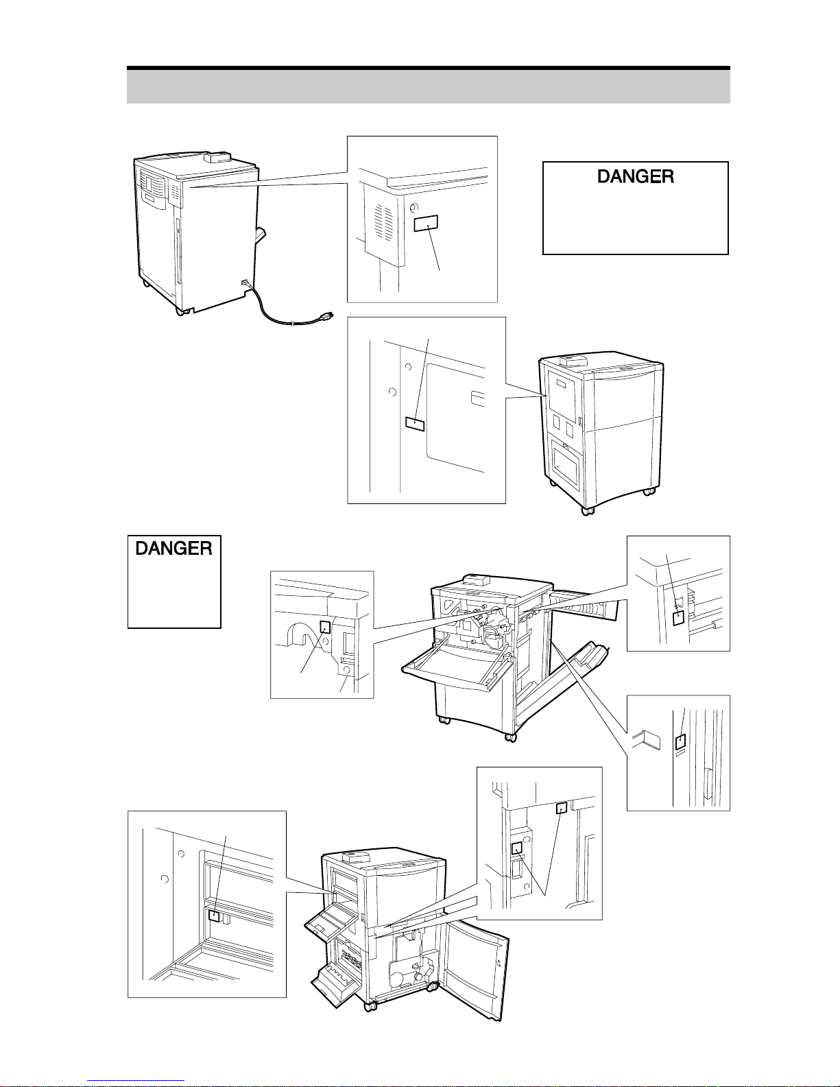
Laser W arning Labels
#1
#1
#2
#2
#2
#2
#2
Label #2
Visible and invisible
laser radiation when
open and interlock
defeated.
AVOID DIRECT
EXPOSURE TO BEAM
Label #1
Visible and invisible laser
radiation when open.
AVOID DIRECT EXPOSURE
TO BEAM

ABOUT THIS MANU AL
● Operations to be performed by the operator are indicated by step numbers 1, 2, 3, and so on,
whereas operations carried out by the machine are marked
★.
[Example]
1. Operate the Host Computer to start printing.
★ The message changes to "Data Busy".
● The mark ( ) used in "Turn the power switch ON ( )." in this manual indicates that the ( ) side
of the power switch should be pressed. The mark (
) in the like manner indicates that the
(
) side of the power switch should be pressed.

SECTION 1 GENERAL PRECAUTIONS
SECTION 2 COMPONENT NAMES AND FUNCTIONS
SECTION 3 OPERATING PROCEDURES
SECTION 4 HOW TO USE THE OPERATION PANEL
SECTION 5 MAINTENANCE
SECTION 6 DONOR/RECEIVER JAM CLEARING PROCEDURES
SECTION 7 TROUBLESHOOTING GUIDE
MAJOR SPECIFICATIONS
APPENDIX
1
2
3
4
5
6
7

Contents
SECTION 1 GENERAL PRECAUTIONS.............................................................................. 1
1.1 Operating Environment......................................................................................... 2
1.2 Room Conditions .................................................................................................. 4
1.3 Installation Space ................................................................................................. 5
1.4 Electrical Hookup.................................................................................................. 6
1.5 Donors and Receivers .......................................................................................... 7
1.6 Duplication Restrictions ........................................................................................ 11
SECTION 2 COMPONENT NAMES AND FUNCTIONS ...................................................... 13
2.1 Overview............................................................................................................... 14
2.2 Operation Panel.................................................................................................... 16
2.3 Alarm .................................................................................................................... 18
2.4 Printing Mechanism .............................................................................................. 20
2.5 Power Saving Mode.............................................................................................. 21
SECTION 3 OPERATING PROCEDURES ........................................................................... 23
3.1 Connecting Other Devices.................................................................................... 24
3.2 Machine Startup ................................................................................................... 25
3.3 Printing ................................................................................................................. 26
3.3.1 Communication Error Display (for ONLINE operation) ............................. 26
3.4 Donor Magazine Replacement ............................................................................. 27
3.5 Receiver Magazine Replacement......................................................................... 32
3.6 Water Replacement.............................................................................................. 35
3.7 Refuse (Used Donor) Disposal............................................................................. 38
3.8 Turning OFF the Power......................................................................................... 41
SECTION 4 HOW TO USE THE OPERATION PANEL......................................................... 43
4.1 Menu..................................................................................................................... 44
4.2 How to Use the Keys ............................................................................................ 48
4.3 Changing the Print Size........................................................................................ 49
4.4 Changing the Power Saving Mode Timer Setup ................................................... 50
4.5 Changing the Resolution (dpi) .............................................................................. 51
4.6 Alarm ON/OFF...................................................................................................... 52
4.7 Fine Adjustment of Print Image Position............................................................... 53
4.8 Checking the Remaining Consumables................................................................ 55
4.9 Setting the Consumables Counters...................................................................... 57
4.10 Setting the Remaining Quantity of Consumables for Alarms................................ 58
4.11 Pictrography 4500 Color Adjustment .................................................................... 60
4.12 Color Adjustment Procedures............................................................................... 61
4.13 Calibration (Standard Color Condition Setup) ...................................................... 62
4.14 Color Control Adjustment Procedures .................................................................. 64

Contents
4.15 Network Setting .................................................................................................... 68
4.15.1 Setting Using the Operation Panel ............................................................ 68
4.15.2 Setup Using Utility ..................................................................................... 72
SECTION 5 MAINTENANCE................................................................................................ 83
5.1 Regular Maintenance Program............................................................................. 84
5.2 Side Air Filter Replacement.................................................................................. 85
5.3 Water Filter Replacement..................................................................................... 86
5.4 Auto Calibrator White Board Cleaning.................................................................. 89
5.5 Scanner Cover Glass Cleaning ............................................................................ 90
SECTION 6 DONOR/RECEIVER JAM CLEARING PROCEDURES................................... 91
6.1 Clearing Donor/Receiver Jams............................................................................. 92
6.2 Jamming at Location "1"....................................................................................... 94
6.3 Jamming at Location "2"....................................................................................... 98
6.4 Jamming at Location "3"....................................................................................... 99
6.5 Jamming at Location "6"....................................................................................... 101
6.6 Jamming at Locations "7 and 8" ........................................................................... 103
6.7 Jamming at Locations "4 and 5" ........................................................................... 104
6.8 Jamming at Locations "5 and 9" ........................................................................... 105
6.9 Jamming at Location "10"..................................................................................... 107
SECTION 7 TROUBLESHOOTING GUIDE.......................................................................... 109
7.1 When a Problem Occurs....................................................................................... 110
7.2 Error Code Display ............................................................................................... 111
MAJOR SPECIFICATIONS .................................................................................................... 113
APPENDIX.............................................................................................................................. 115

Blank Page.

1
SECTION 1 GENERAL PRECAUTIONS
Before using this product, read and understand this section thoroughly.
Safety precautions include WARNING and CA UTION. Supplementary explanations f or operations
are indicated as IMPORTANT or NOTE.
WARNING: Indicates a situation which, if not avoided, may result in death or serious injury to
personnel.
CAUTION: Indicates a situation which, if not avoided, may result in a minor or somewhat
more serious injury to personnel. It also indicates a situation which may cause
physical damage to the product.
IMPORTANT: Indicates an item which may degrade the machine’s performance or cause a
machine breakdown should the operator do something wrong.
NOTE: Indicates a machine/consumable handling precaution or a supplementary explanation for
an operation.
1.1 Operating Environment.................................................... 2
1.2 Room Conditions ............................................................. 4
1.3 Installation Space ............................................................ 5
1.4 Electrical Hookup............................................................. 6
1.5 Donors and Receivers ..................................................... 7
1.6 Duplication Restrictions ................................................... 11

2
1.1 Operating Environment
General Precautions
● Follow the instructions provided in this manual only.
WARNING: ● Use the indicated voltage only . Do not use an e xtension cord with an insufficient
power rating or serially connected extension cords as fire or electrical shock
may result.
● A 2-pin outlet cannot be grounded. In case of leakage, electrical shock may
result.
● Do not scratch, damage, or physically alter the power cord. Do not place a
heavy object on the power cable . Do not f orcibly pull or bend the po wer cable .
Such acts may damage the power cable resulting in fire or electrical shock.
● Do not touch the power plug with wet hands. An electrical shock may result.
● Do not modify the product. Fire or electrical shock may result. The product
contains semiconductor lasers. If modified, the user ma y be e xposed to laser
light.
● Do not remove covers or parts tightened with screws. This may cause injury
or electrical shock to personnel.
● Do not place metal objects or receptacles containing water, such as a flower
vase, potted flower, or water glass on the machine. If water should fall inside
the machine, fire or electrical shock may result.
● If you notice smoke rising from the machine, a high frame temperature, strange
odors or abnormal sounds, immediately turn the power switch OFF (
), unplug
the power cable and contact your local dealer. If the machine is used in such
a condition, fire or electrical shock may result.
CAUTION: ● Do not place the machine on an unstable surf ace , such as an unsteady tab le
top or a tilted place. The machine ma y drop or fall, causing injury to personnel.
● Once the machine is installed, lock the casters. Otherwise, the machine may
move or fall down, causing injury to personnel.
● Before moving the machine, always unplug the power cord from the outlet.
Otherwise, the cable may be damaged, causing fire or electrical shock.
● When you unplug the power cord, always hold the plug. Pulling the power
cord may expose wires or cause wires to break, causing fire or electrical
shock.
● When cleaning the machine cabinet, do not use a spray cleaner containing
flammable materials. A fire may be caused.
● Do not press the open/close switch of a door on the machine when it is open.
The switch is for protection. The machine may assume the door is closed and
start operating, causing injury to personnel.

3
1
GENERAL PRECAUTIONS
CAUTION: ● Do not drink water in the water bottle or give it to animals.
● When clearing a jam, do not touch the thermal processing unit after opening
it. The thermal processing unit is very hot.
● When the machine is not to be used for a long time (as dur ing a vacation),
unplug the power cord for safety.
IMPORTANT:
● Do not use solv ents such as benzine or thinner to clean the machine cabinet.
Wipe with water or a mild detergent.
● Do not drop f oreign material such as paper clips, or staples into the machine.
● Do not lean against the machine or sit on it. Do not place hea vy objects on the
machine or subject it to a large impact.
● Use Fuji-recommended parts for repairs. If other par ts are used, Fujifilm will
not ensure the quality of the machine.
● The water used in the machine should have the total hardness of under 100
ppm and a residual chlorine content of under 1 ppm. Distilled water is
recommended.
1.1 Operating Environment

4
1.2 Room Conditions
For normal and safe operation, install the machine in the following environment.
● Temperature: 15°C to 28°C (Free from moisture condensation)
If the temperature in the room is over 28°C or under 15°C, proper printing quality may not be
assured. At low temperatures, the machine takes a long time to start printing or errors may
occur.
When a cold room is warmed rapidly, water droplets are formed inside the machine (moisture
condensation), causing donor/receiver jamming or print quality deterioration. Use the machine
in a place not subject to sharp changes in the temperature.
● Humidity: 30%RH to 70%RH
If the humidity in the room is over 70%RH, a transf er error may occur in the donor or receiv er , or
the receivers may become damp , causing print quality deterioration. Do not install the machine
in a place near a water tap, boiler, humidifier, air conditioner, or heater. And always keep the
room humidity at 30%RH to 70%RH.
● Ventilation
Make sure the installation site is well-v entilated and not dusty.
IMPORTANT: A dusty environment may cause spotting* on the picture surface.
● If the machine, donor, or receiver magazine is subject to direct sunlight, light from electronic
flash, or strong reflected light, use curtains or blinds to avoid this.
NOTE: A strong light may cause fogging**.
● The installation site must be free of ammonia, formalin, and sulfurous acid vapor . Such vapors
will cause a deterioration in printing quality and rust on the machine.
● Do not place volatile combustibles, such as thinner or alcohol, near the machine.
● Mak e sure the installation room floor is level, stab le, capable of withstanding the machine weight,
and not subject to strong vibration. Each caster can withstand a weight of about 30 kg.
* Spotting: White dots
** Fogging: Print discoloration caused by extraneous light on the photo-sensitive material (donor).
5
1
GENERAL PRECAUTIONS
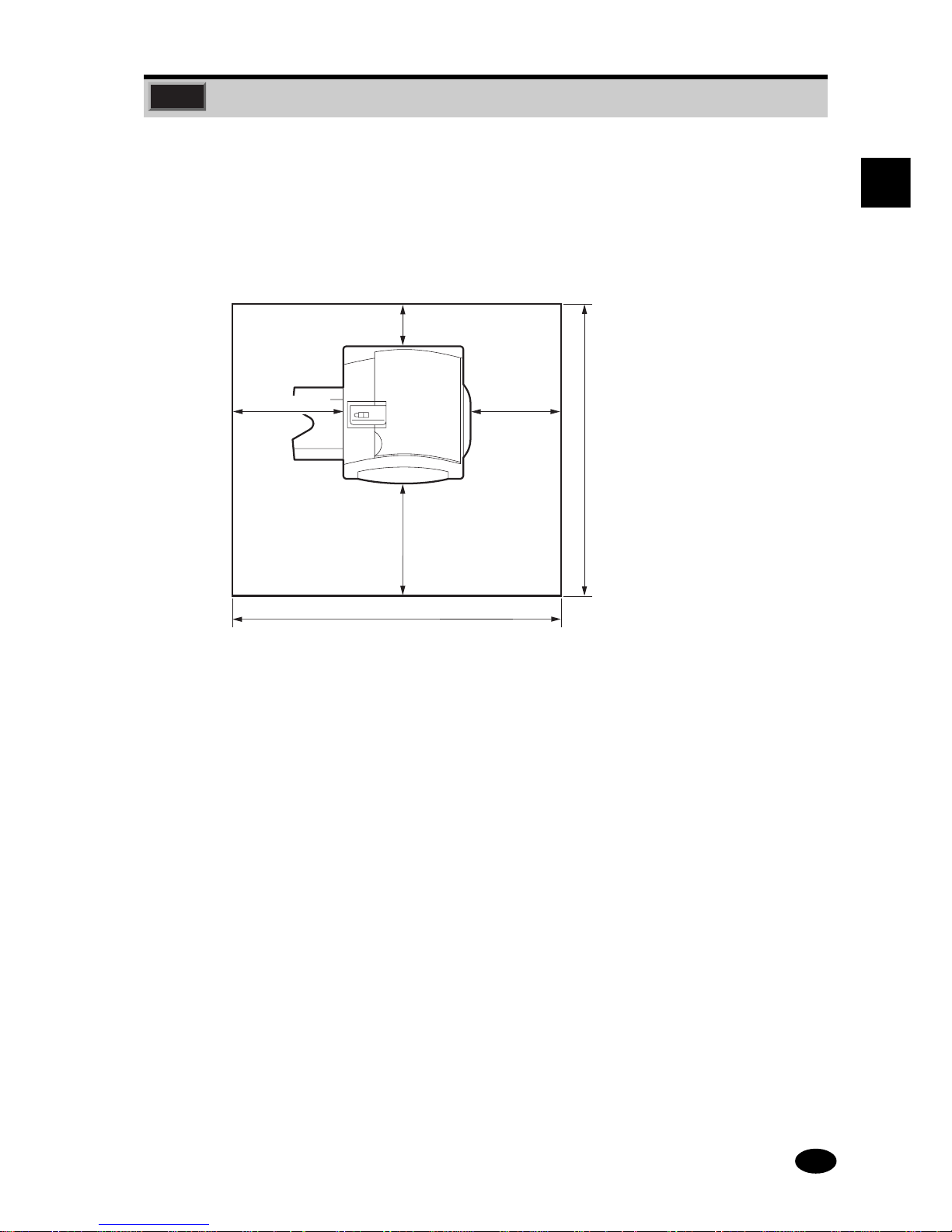
1.3 Installation Space
Secure the amount of space shown below to ensure the proper operation, replacement of
consumables, and maintenance of the machine.
IMPORTANT: There is a v ent at the rear of the machine. Provide a minimum clearance of 8
in. (20 cm) between the vent and the wall.
Unit: mm
17in.(430mm)
23in.(580mm)
8in.(200mm)
56in.
(1416mm)
62in.(1565mm)
21in.(530mm)

6
1.4 Electrical Hookup
● Connect the power plug directly into a 120V ±10V, 60 Hz grounded outlet (3-pin) which has a
power rating of 15 A or more.
WARNING: ● DO NOT USE a two-pin power outlet which is not grounded, as an electrical
shock may result when short circuiting occurs.
● Use the indicated power supply voltage only. Never use an extension cord
with an inadequate rating. If such a cord is used, abnormal heat generation,
smoke or other abnormal phenomena may occur.
● Perform the following checks on a periodic basis.
●
Make sure the power plug is properly inserted into a dedicated power outlet.
●
Check the power plug and cable for abnormal heat generation.
●
Make sure the power cable is not cracked or damaged.
7
1
GENERAL PRECAUTIONS
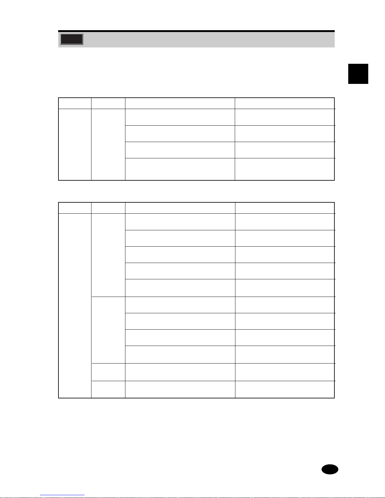
● Use the donors and receiv ers specified below.
Donors
Name Abbreviation Size Remarks
323 mm x 92 m Base: Paper
(Equivalent to 182 Double Letter Wide sheets)
305 mm x 92 m Base: Paper
(Equivalent to 194 Double Letter size sheets)
Pictro PZ-D ER
262 mm x 92 m Base: Paper
(Equivalent to 266 10 x 12 size sheets)
135 mm x 92 m Base: Paper
(Equivalent to 422 5R size sheets
or 479 4R size sheets)
Receivers
Name Abbreviation Size Remarks
Pictro PZ -SG ER 315 mm x 60 m Standard thickness, glossy,
(Equivalent to 129 Double Letter Wide sheets) with backprinting
279 mm x 60 m Standard thickness, glossy,
(Equivalent to 138 Double Letter size sheets) with backprinting
254 mm x 60 m Standard thickness, glossy,
(Equivalent to 196 10 x 12 size sheets) with backprinting
127 mm x 60 m Standard thickness, glossy,
(Equivalent to 337 5R size sheets) with backprinting
102 mm x 60 m Standard thickness, glossy,
(Equivalent to 394 4R size sheets) with backprinting
PZ-SM ER 315 mm x 60 m Standard thickness, semi-glossy,
(Equivalent to 129 Double Letter Wide size sheets) with backprinting
279 mm x 60 m Standard thickness, semi-glossy,
(Equivalent to 138 Double Letter size sheets) with backprinting
254 mm x 60 m Standard thickness, semi-glossy,
(Equivalent to 196 10 x 12 size sheets) with backprinting
102mm x 60 m Standard thickness, semi-glossy,
(Equivalent to 394 4R size sheets) with backprinting
PZ-LG ER 279 mm x 77 m Lightwight paper, glossy,
(Equivalent to 178 Double Letter size sheets) without backprinting
PZ-LM ER 102 mm x 77 m Lightwight paper, semi-glossy,
(Equivalent to 506 4R size sheets) without backprinting
1.5 Donors and Receivers
8
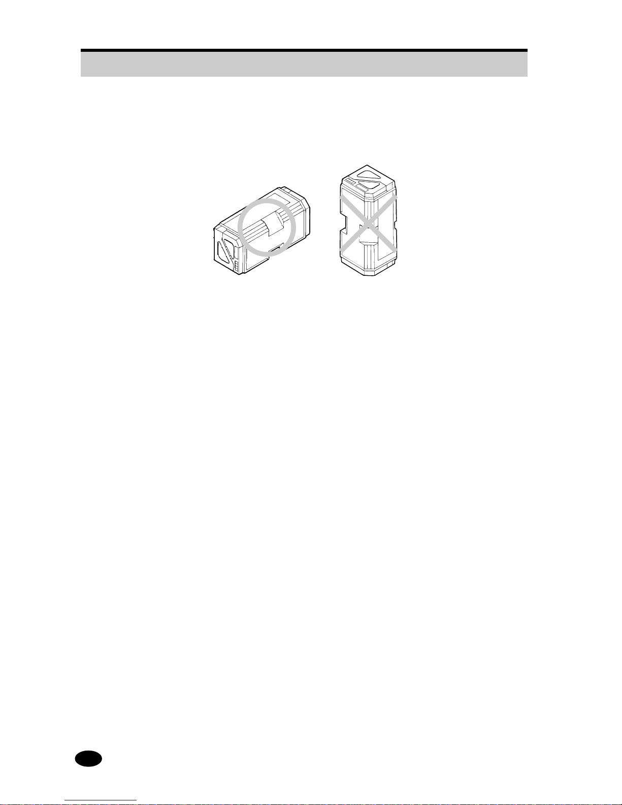
● When storing the donor (the donor magazine) or receiv er (the receiv er magazine), place it in a
horizontal position. If stored in an upright position, the donor/receiver roll may become loose
and impossible to pull out of the magazine.
IMPORTANT: If a sealed donor magazine/receiv er magazine is left in a room for a long period
or in a hot and damp place, good printing quality may not be obtained. The
magazine must be stored in a cool, dark place not exposed to direct sunlight. If
the magazine will be stored for longer than one month, storage at
10°C, 60%RH or less is recommended.
● When unsealing the donor (or the donor magazine), make sure that it is not exposed to direct
sunlight.
● After a magazine is unsealed, it must not be placed on the floor or in a dusty location as
deterioration in print quality may result.
● If the inner door of the donor magazine compartment (see (13) in 2.1) is open, the donor leading
edge will be exposed to extraneous light.
● After a magazine is unsealed, it should be immediately inserted into the machine. If a donor
magazine is left in a bright place for extended periods of time, the donor will be exposed to
extraneous light and become unusable.
● Prepare a magazine for each size of donor and receiver used. The donor is photosensitive.
Once a donor roll is inserted in a magazine, it cannot be replaced with another donor roll. It is
also recommended that the receiver not be replaced after insertion into a magazine, otherwise
deterioration in print quality may result.
IMPORTANT:
● To assure good print quality, it is recommended that the donor/receiver be
used within one month after unsealing.
● If the machine is not to be used for a period of longer than one week, take the
donor and receiver magazines out of the machine and store them in a cool
dark place. Also empty the water bottle.
1.5 Donors and Receivers
9
1
GENERAL PRECAUTIONS
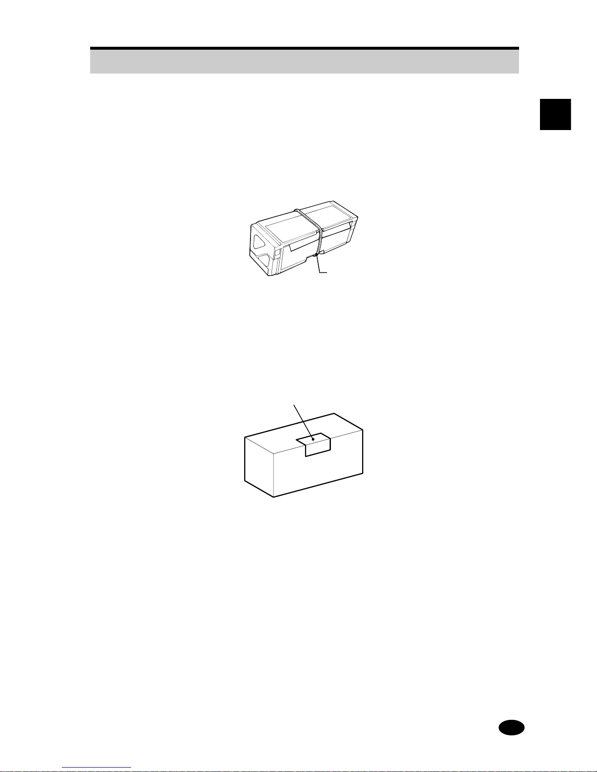
● When storing an unsealed magazine (D or R), place it in a cool dark place.
It is recommended that the donor/receiver leading end be retained with a
rubber band to prevent it from being wound into the magazine. Do not tape
down the donor/receiver leading edge because residual tape adhesive may
adhere to the edge, contaminating the donor/receiver and causing a malfunction.
Rubber band
● When using donor magazine/receiver magazine stored under refrigeration, allow it to rise to
room temperature before taking it out of the inner bag to prevent moisture condensation.
● Use the donor/receiver before the expiration date.
● When the donor is replaced or is used for more than one month, the print color balance and
density may change. You should therefore, perform a calibration (see page 61).
The production number and
expiration date are indicated here.
● The refuse (used donor) retains negativ e images. Any refuse containing confidential data should
be shredded and properly disposed of as industrial waste (see page 38).
● When storing finished prints, keep them out of direct sunlight.
● The quality of the prints is affected by various environmental conditions (heat, humidity, light,
and air pollution).
Recommended storage conditions
● Store with good ventilation at 25°C, 30%RH to 60%RH
● Store at 10°C or less, 30%RH to 50%RH when storing for long periods
● When stacking prints, use care to prevent the image surfaces coming into contact with each
other because color dye transfer may occur.
1.5 Donors and Receivers
10
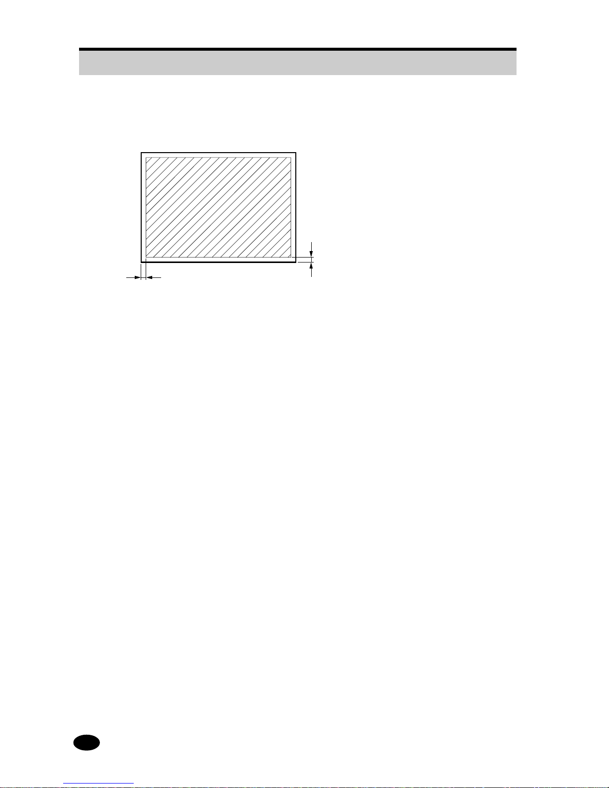
● Image quality is guaranteed over the entire sheet except for a 0.2- in. (5-mm) boarder along
each sides (0.24 in, (6 mm) in the case of Double Letter wide sheets).
0.2in. (5mm)
(0.24in. (6mm) for Double Letter wide sheets)
0.2in. (5mm)
(0.24in. (6mm) for Double Letter wide sheets)
● The trailing end of the receiv er has an end-detection hole . Therefore, the last print produced at
the end of a receiver roll may have a hole in it. Such a print is not included in the guaranteed
number of prints.
● Prints containing the cut edge at the start of the receiver roll or the end-detection hole at the end
of the roll are not included in the guaranteed number of prints.
1.5 Donors and Receivers

11
1
GENERAL PRECAUTIONS
1.6 Duplication Restrictions
The possession of duplication equipment does not automatically entitle the owner to make copies.
There are cases where legal restrictions are enforced.
CAUTION: ● There are items whose duplication is prohibited by law. DO NOT duplicate
such items, or make duplicates that may be used for illegal purposes.
● In order to copy mater ials that are protected by copyrights, you must first
obtain permission from the copyright owner. Reproduction without such
permission constitutes an infringement of the law.

12
Blank Page.

13
SECTION 2
COMPONENT NAMES AND FUNCTIONS
2.1 Overview.......................................................................... 14
2.2 Operation Panel............................................................... 16
2.3 Alarm ............................................................................... 18
2.4 Printing Mechanism ......................................................... 20
2.5 Power Saving Mode......................................................... 21
14
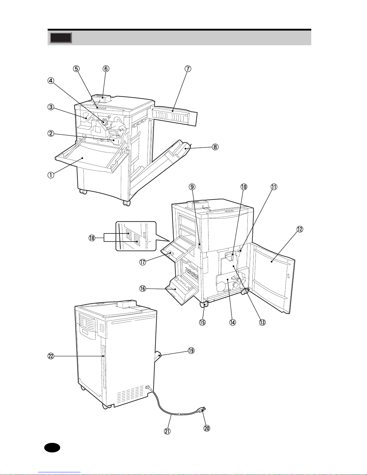
2.1 Overview
PO2F001J

15
2
COMPONENT NAMES AND FUNCTIONS
2.1 Overview
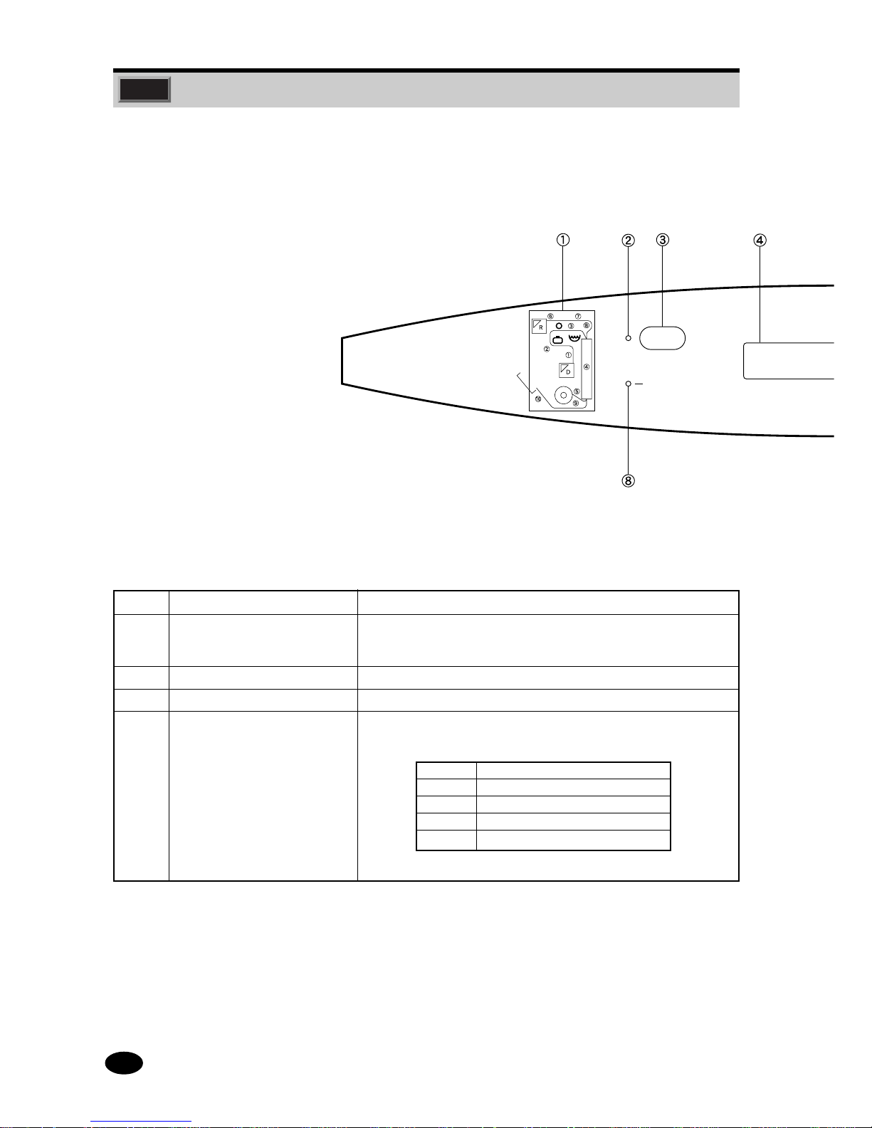
Number Name Function
1 Front Door Is opened to replace magazine or water, or to clear a donor/receiver
jam.
2 Water Bottle Contains the water to be applied to the donor.
3 Receiver Magazine Compartment Contains the receiver magazine.
4 Water Filter Removes any foreign matter from the water.
5 Operation Panel Operation keys and indicator lamps are located here
(see pages 16 and 17).
6 Auto Calibrator Reads the density reference pattern and performs the calibration
(standard color condition setup). (See page 61.)
7 Right-hand Side Upper Door Is opened to clear a donor/receiver jam.
8 Thermal Processing Unit Transfers an image to the receiver. The door of this unit is opened
to clear a donor/receiver jam.
9 Power Switch Turns the Power ON ( )and OFF ( ).
10 Inner Door Lock Lever Locks the inner door. Also releases the nip roller for donor
transport.
11 Thermal Processing Unit Opens the thermal processing unit. Also opens the thermal unit
Release Lever door to clear a donor/receiver jam.
12 Front Lower Door Is opened to replace the donor magazine or to clear a donor/receiver
jam.
13 Inner Door/Donor Magazine Contains the donor magazine.
Compartment
14 Refuse Compartment Is opened for refuse removal.
15 Casters Two casters are provided at both the front and rear for moving the
machine.
16 Left-hand Side Lower Door Is opened to clear a donor/receiver jam.
17 Left-hand Side Upper Door Is opened to clear a donor/receiver jam.
18 Side Air Filter Cleans the air drawn in by the fan to cool the interior of the machine.
19 Print Tray Finished prints are discharged into this tray.
20 Power Plug Three-pin grounded plug
21 Power Cable Connects the machine to a power outlet.
22 Interface Connector Connects the Ethernet cable to the main body.
16
Number Name Function
1 Transfer Monitor Indicates by LEDs the processing state of the donor and receiver.
Alsming and errors related to the donor, receiver, water, and water
filter.
2 ONLINE indicator lamp Lights when the machine is online and goes off when it is offline.
3 ONLINE indicator key Turns the machine online or offline.
4 Message Display Indicates the machine status, the size of the donor, and the type of
receiver used. The donor size is indicated as follows.
Indication Size of donor
LL 323 mm (Double Letter wide,etc.)
L 305 mm (Double Letter and Letter)
M 262 mm (10 x 12 and 10 x 8)
S 135 mm (4R,etc.)
Also indicates the key(s) that may be used.
ON LINE
DATA
2.2 Operation Panel
17
2
COMPONENT NAMES AND FUNCTIONS
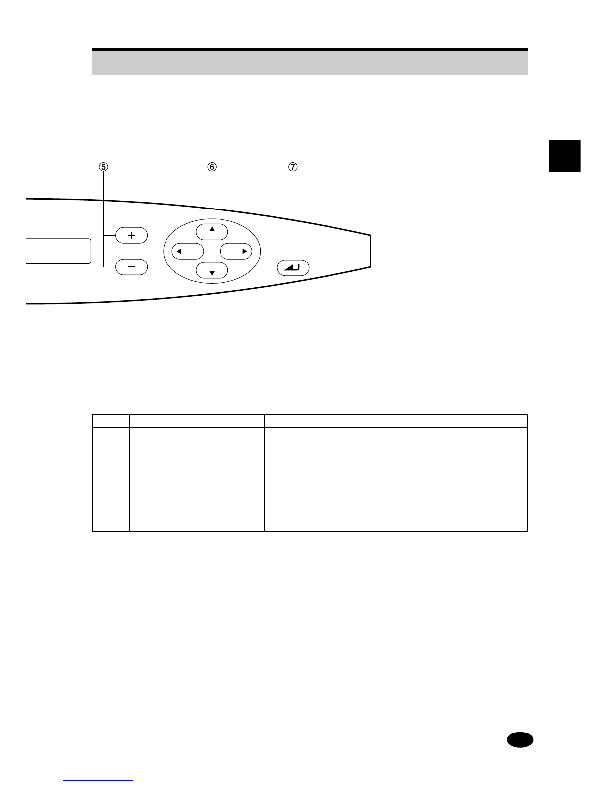
Number Name Function
5 + key / – key Press to enter the value for each parameter, including print
size and color control.
6 MODE key PREV key: Press to return to the previous menu.
NEXT key: Press to proceed to the next menu.
ESC key: Press to go up one menu.
SEL key: Press to go down one menu.
7 EXEC key Press to execute the selected menu.
8 DATA lamp Indicates that data is being received through an external interface.
2.2 Operation Panel
ESC
PREV
SEL
NEXT

18
2.3 Alarm
● An alarm sounds under the following conditions.
● The type of alarm depends on the machine condition.
Alarm sound Machine condition
Beep (a single short beep) ● The machine has accepted a key entry.
Beep-beep-beep-beep, beep-beep-beep-beep,
● The donor/receiver is jammed.
... (four successive short beeps, repeated)
● The loaded donor or receiver is used up.
● Water replacement is needed, or the water level is low.
● The refuse compartment is filled with discharged refuse.
● The water filter needs to be replaced.
● No magazine is set in position.
Beep, beep, ...
● An E error occurred.
(a single long beep, repeated)
NOTE:
● The alarm stops when the door is opened.
● If "Alarm OFF" is selected in advance with the configuration function, no alarm will sound (except for
E errors).

19
2
COMPONENT NAMES AND FUNCTIONS
Blank Page.
20
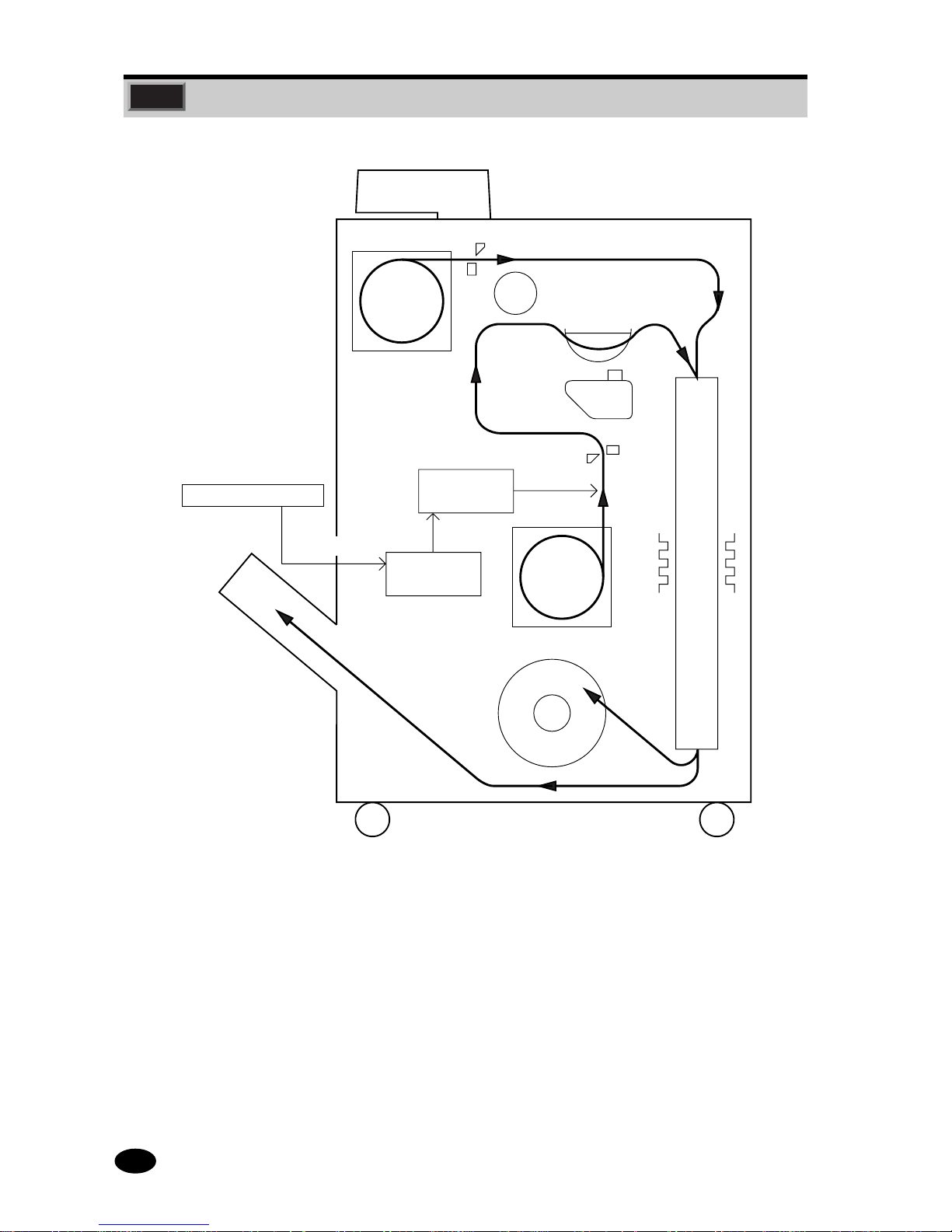
2.4 Printing Mechanism
1. The digital image data received from the host computer is stored in the image memory.
2. The donor is exposed by laser while being transported. The light quantity is controlled according
to the image data.
3. The donor is cut to the specified length.
4. The receiver (paper) is pulled out and cut to the specified length.
5. The donor is coated with water while being transported.
6. The donor and receiver come in contact with each other and are carried onto the drum surface
for thermal transfer.
7. The donor is peeled from the receiver.
8. The receiver is dried and discharged into the print tray.
Paper
Cutter
Auto calibrator
5. Water
coating
Cutter
Laser
exposure unit
Exposure
Image
memory
Donor
6. Thermal processing & transfer
Heater
7. Peeling
8. Drying
Color print
Refuse
2. Donor
pulled out/
exposure
3. Donor cut
4. Receiver pulled out
Digital image data
1. Data received

21
2
COMPONENT NAMES AND FUNCTIONS
2.5 Power Saving Mode
Power Saving Mode
When the machine is not used for a specific duration (10, 30, or 60 minutes) following a printing
operation, the machine automatically decreases the temperature of the thermal processing unit in
order to reduce power consumption.
Power saving mode is released when any ke y on the panel is pressed or when a print instruction is
issued from the host computer.
 Loading...