

FujiFilm NXT Setup Manual

Fuji Scalable Placement Platform
NXT
Setup Manual
QD002-07
R

Consult Fuji beforehand if you are considering selling this
equipment to a third party after it has been installed.
Fuji Scalable Placement Platform
NXT
Setup Manual
The manuals listed below are shipped with the NXT machine.
NXT Setup Manual
NXT System Reference
NXT Mechanical Reference
FUJI Intelligent Feeder Manual
NXT Programming Manual
In order to operate this machine in the safest and most efficient
manner, please read the provided manuals thoroughly and
observe all instructions and warnings.
Keep these manuals in an accessible location near the machine.
QD002-07
R

Copyrights
All rights regarding this manual are reserved by Fuji Machine Manufacturing Co., Ltd. This manual may
not, in whole or in part, be reproduced by any means (electronic, mechanical or otherwise), or reused in
any way, without the prior written permission of Fuji Machine Manufacturing Co., Ltd.
Trademark Rights
R
is a trademark of Fuji Machine Manufacturing Co., Ltd., and registered in the following
countries: Austria, Belgium, Denmark, Finland, France, Germany, Greece, Indonesia, Ireland, Italy, Jap an,
Korea, Luxembourg, the Netherlands, Portugal, Spain, Sweden, the U.K., and the U.S.A.
W arranty and Liability
Fuji Machine Manufacturing Co., Ltd. accepts no responsibility for situations that may arise due to any of
the following:
• The use of third party parts.
• The use of non-genuine Fuji parts.
• Incorrect settings made by the customer.
• Improper use of Fuji equipment.
Notice
Fuji Machine Manufacturing Co., Ltd. reserves the right to change the content of this manual without
notice.
Every effort has been made to ensure that this manual is correct in every detail. However, please contact
Fuji in the unlikely event that errors or omissions are detected.
Fuji Machine Manufacturing Co., Ltd. accepts no liability whatsoever for damages that may arise as a
result of this manual, with the exception of problems that originate in our products.

QD002-07 Contents
Contents
1. Safety Guideline................................................... 1
1.1 About Symbols ................................................. 1
1.1.1 Degree of Hazards ................................................. 1
1.1.2 Examples of the Symbols....................................... 1
1.2 Safety Rules for All Machine Types.................. 2
1.3 Safety Rules for NXT........................................ 6
1.3.1 Main Unit ................................................................ 6
1.3.2 Tray Unit-L............................................................ 10
1.3.3 Tray Unit-M........................................................... 11
1.4 Safety Labels.................................................. 12
1.4.1 NXT Safety Label Explanations............................ 15
1.5 The EMERGENCY STOP Button................... 16
1.6 Locking System.............................................. 17
1.6.1 Lockout Procedure ............................................... 17
1.6.2 Unlocking Procedure............................................ 19
2. Setting Up the NXT............................................. 21
2.1 Introduction..................................................... 21
3. Machine Set Up.................................................. 23
3.1 Moving a Machine .......................................... 23
3.1.1 Precautions when moving the machine................ 23
3.1.2 Transport Procedure............................................. 24
3.2 Removing Fixing Brackets.............................. 28
3.2.1 Procedure............................................................. 28
3.3 Removing the Linear Motor Shaft Protective
Covers .............................................................. 31
3.3.1 Procedure............................................................. 31
3.4 Making Basic Connections............................. 32
3.4.1 Electric power supply............................................ 32
3.4.2 Network Cable...................................................... 34
3.4.3 Air supply.............................................................. 35
3.5 Leveling the Machine...................................... 36
NXT Setup Manual i

Contents QD002-07
3.5.1 Procedure............................................................. 36
3.6 Making Network Settings ............................... 39
3.6.1 Procedure............................................................. 39
3.7 Connecting NXT Bases.................................. 40
3.7.1 Connecting Method............................................... 41
3.7.2 Signal Cable Connecting Diagram
(NXT - NXT - NXT)................................................ 43
3.8 Installing Additional Dependent Bases........... 44
3.8.1 Extension Patterns................................................ 44
3.8.2 Pneumatic Connections........................................ 45
3.8.3 Using One 2M Base.............................................. 46
3.8.4 Using Two 2M Bases............................................ 51
3.8.5 Using Three 2M Bases......................................... 57
3.8.6 Using Four 2M Bases........................................... 63
3.8.7 Using One 2M Base and an Independent
4M Base (1)............................................................ 68
3.8.8 Using Two 2M Bases and an Independent
4M Base (1)............................................................ 75
3.8.9 Using One 2M Base and an Independent
4M Base (2)............................................................ 84
3.8.10 Using Two 2M Bases and an Independent
4M Base (2)............................................................ 91
3.8.11 Using One 4M Base and an Independent
4M Base (1).......................................................... 100
3.8.12 Using One 4M Base and an Independent
4M Base (2).......................................................... 106
3.8.13 Fastening Extensions ....................................... 112
3.9 Connecting an NXT Base to Other Machine Types
....................................................................... 114
3.9.1 Procedure........................................................... 115
3.9.2 Signal Cable Connecting Diagram
(Other machine type - NXT - Other machine type) 116
3.10 Tray Unit-L ................................................. 117
3.10.1 Adjusting the Height and the Levelness ........... 117
4. Setting Up NXT Machines in Flexa.................. 121
4.1 Introduction .................................................. 121
4.2 General Procedures..................................... 121
ii NXT Setup Manual

QD002-07 Contents
4.2.1 Creating a factory............................................... 121
4.2.2 Creating a line .................................................... 121
4.2.3 Creating a machine ............................................ 122
5. Accessory Software Installation........................ 125
5.1 Introduction................................................... 125
5.1.1 Installation outline............................................... 125
5.2 Required Items............................................. 126
5.2.1 Required hardware............................................. 126
5.3 Installing Fuji Flexa....................................... 128
5.4 Installing the NXT Accessory Software Server 136
5.5 Installing the Realtime Workingrate Buffer
Service........................................................... 145
6. Setting Up Fujitrax Verifier ................................ 147
6.1 Introduction................................................... 147
6.2 Required Items............................................. 147
6.2.1 Setting up and running the Central Server......... 147
6.2.2 Adding the NXT to the Fujitrax line configuration 148
6.2.3 Setting the NXT Fujitrax configuration settings .. 150
6.2.4 Registering users for Kit Handy access.............. 151
NXT Setup Manual iii

Contents QD002-07
MEMO:
iv NXT Setup Manual
QD002-07 1. Safety Guideline
1. Safety Guideline
Fuji machines are designed and produced with safety as one of our main considerations.
However, even a perfectly designed machine can be damaged, or someone can still be
injured if the user does not follow the safety rules. It is the responsibility of the user to make
sure all safety rules are followed during operation and maintenance.
Be sure to read these safety rules before operating the machine. Keep this manual close
at hand when operating the machine.
1.1 About Symbols
To avoid injury to persons and damage to the machine, Fuji employs a number of messages
and symbols that are used in manuals and on the machines. Be sure you understand the
meanings of these symbols before reading the manual.
1.1.1 Degree of Hazards Symbol Definition
DANGER
WARNING
CAUTION
Failure to observe this hazard warning will lead to severe
injury or death.
Failure to observe this hazard warning may lead to severe
injury or death.
Failure to observe this hazard warning may lead to
personal injury or damage to the machine.
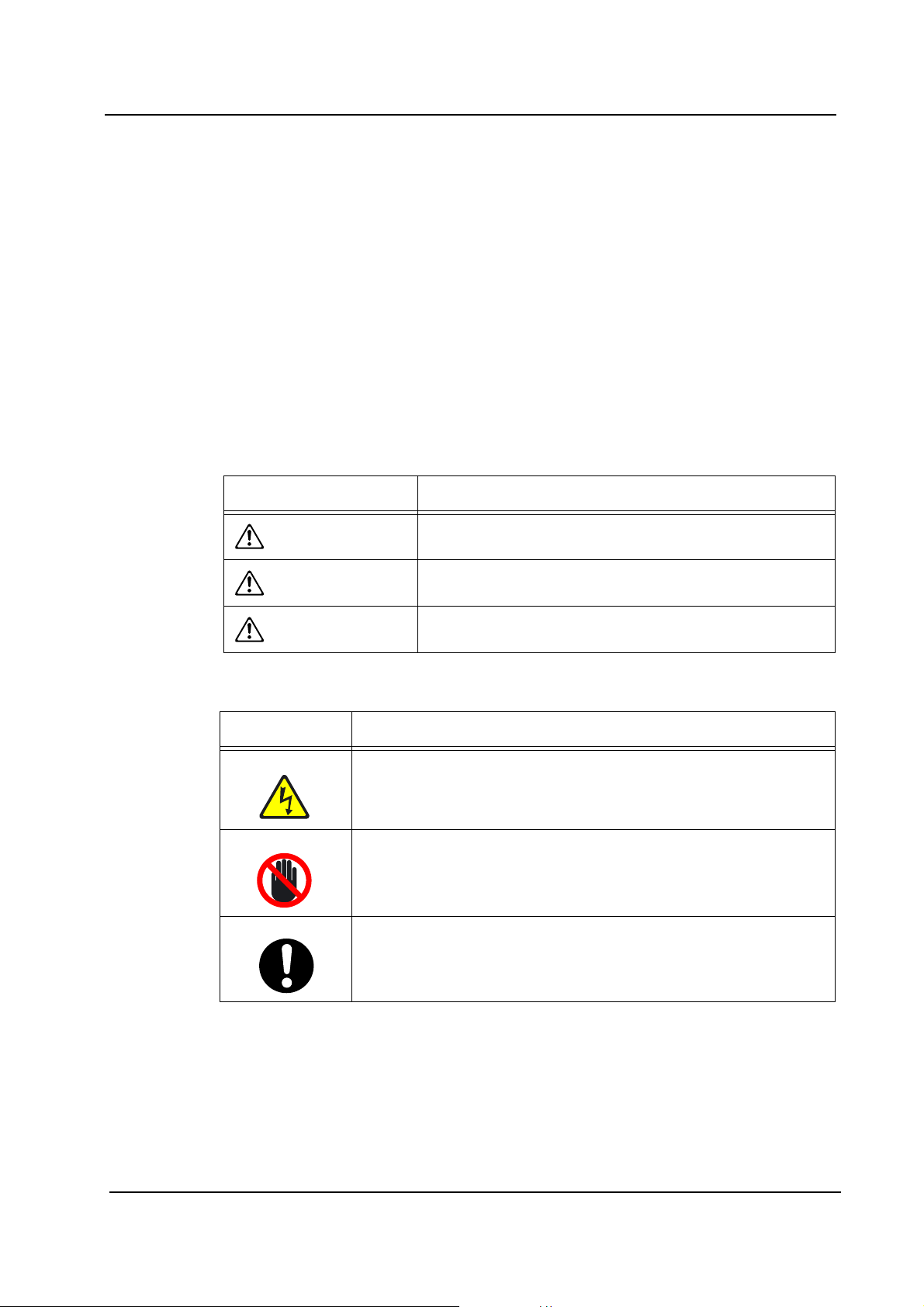
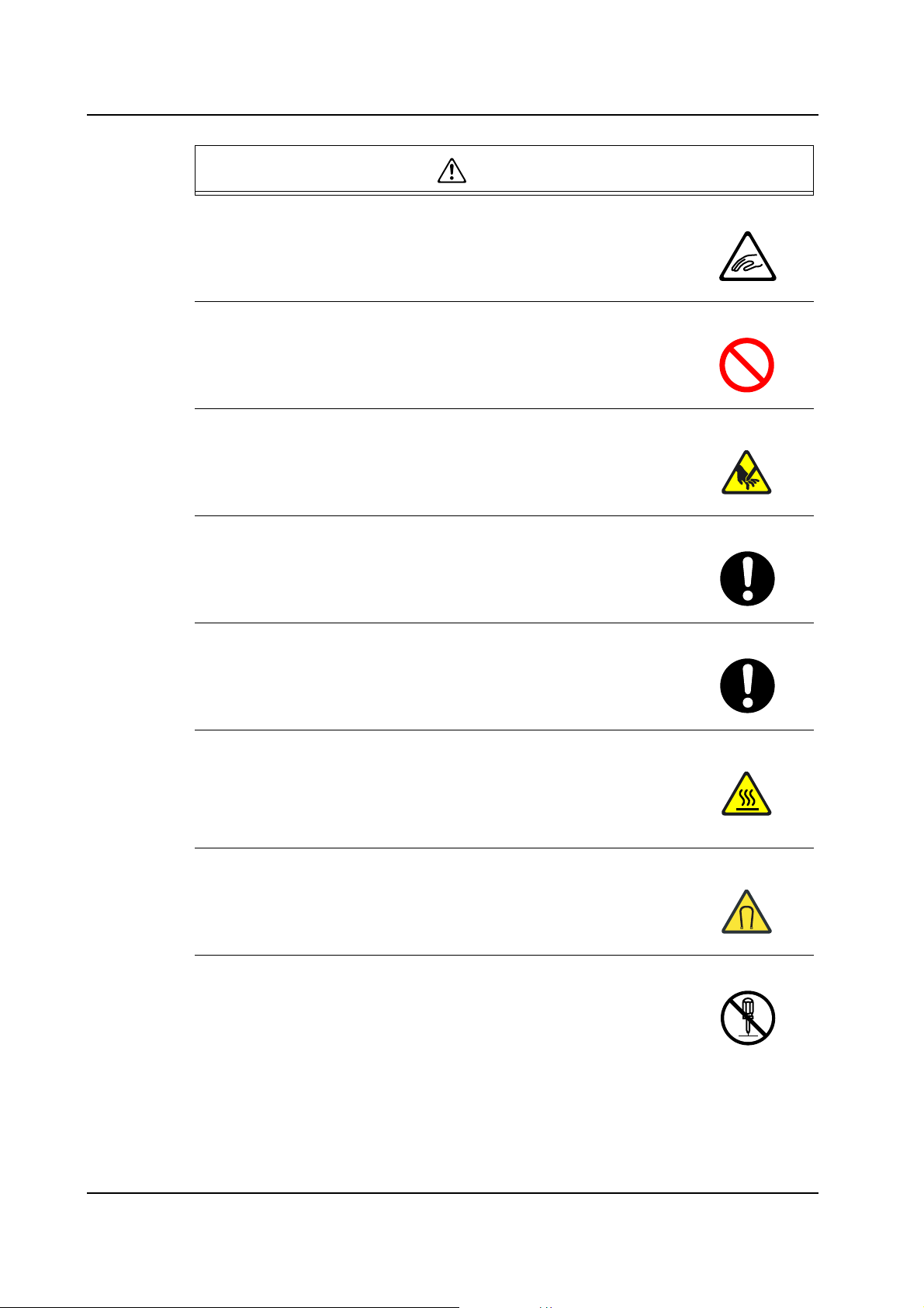
1.1.2 Examples of the Symbols
Symbol Explanation
Hazard
A triangle is used to draw your attention to a hazard. The symbol
inside the triangle indicates the nature of the hazard (in this case,
electrical shock).
Prohibition
A circle with a diagonal line is used to draw your attention to an
operation that is prohibited. The symbol inside the circle indicates
the nature of the operation (in this case, disassembly).
A circle with an exclamation mark is used to draw your attention to to
a mandatory action. In other words, you are required to carefully
carry out the given instructions.
NXT Setup Manual 1
1. Safety Guideline QD002-07
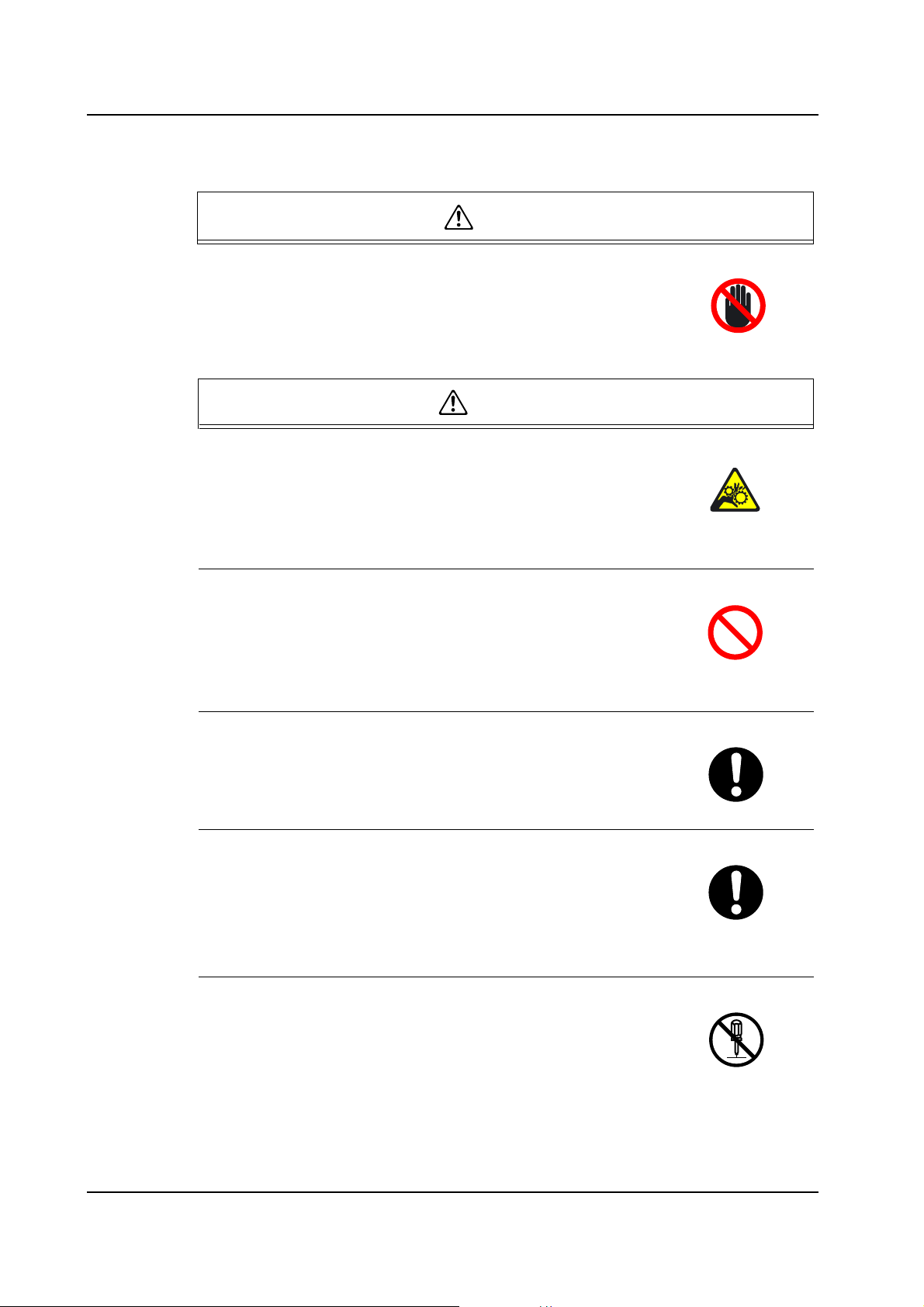
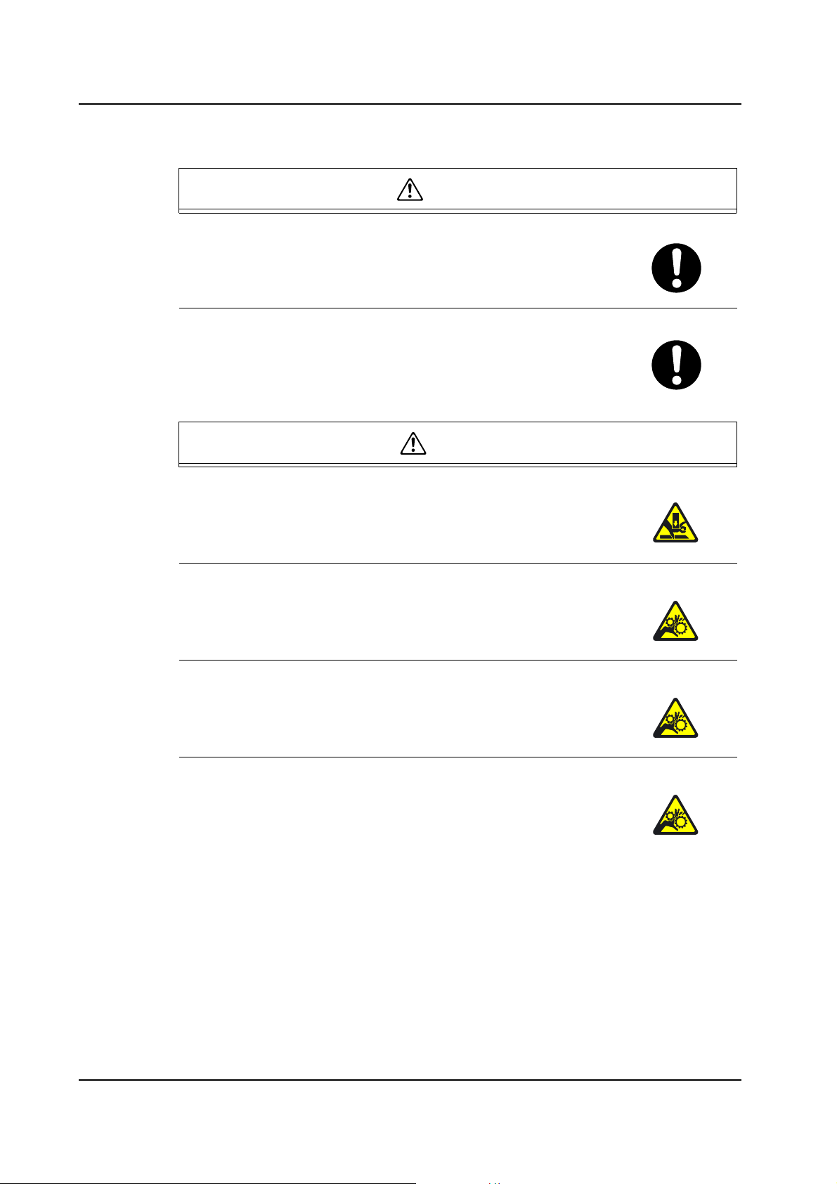
1.2 Safety Rules for All Machine Types
DANGER
Do not approach moving parts during automatic or manual
operation
• Do not place hands or other body parts inside the machine
during automatic operation or positioning. Body parts or
clothing may be caught in the machine causing personal injury.
WARNING
Do not insert hands or other body parts into the conveyor
inlets
• Body parts may get caught in the machine resulting in injury.
• If using a single machine independently, install safety covers or
interlock sensors at the conveyor openings, in accordance with
your local safety regulations, to prevent injuries at the conveyor.
Do not operate the machine with the safety covers or doors
open
• When safety covers or doors are removed, body parts or
clothing may be caught in the machine causing personal injury.
• When maintenance works are completed, return the safety
covers and doors to their original (closed) position.
Always verify the position of the EMERGENCY STOP
buttons before operating the machine
• Always be aware of the positions of the EMERGENCY STOP
buttons so that they can be pressed quickly in case of an
emergency.
Check the safety functions before starting operation
• Before starting the machine check the operation of the
EMERGENCY STOP button, the safety switches on the covers,
doors and all other machine safety feature s.
• Contact a Fuji serviceman immediately if any of the safety
functions fails.
Do not remove safety switches or disarm the safety
functions
• Do not short or remove the machine’s safety switches. Persons
working on the machine may be seriously injured if operation
commands are issued by mistake.
2 NXT Setup Manual
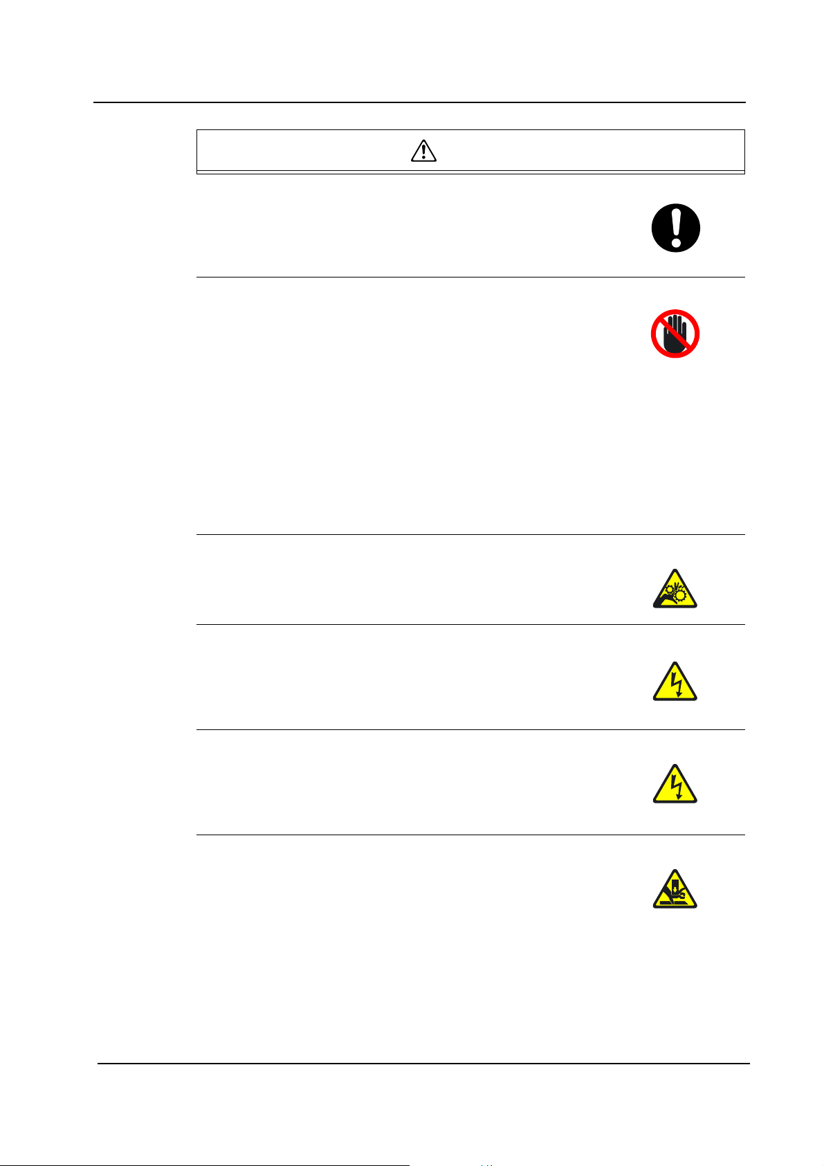
QD002-07 1. Safety Guideline
WARNING
Check that there is nobody inside the machine when
working on the machine with two persons or more
• Verify that nobody is within or near the machine before
operating the machine. Operating the machine may cause
injury to the person who is carrying out maintenance.
Do not approach a machine that has stopped moving
• There are times during automatic operation when the machine
may appear to have stopped while it is waiting for a board,
waiting for the next machine, reading marks, transmitting data,
etc. In such cases, once certain conditions are fulfilled, the
machine will begin moving again automatically, so care should
be taken. Only approach the machine after the EMERGENCY
STOP button has been pressed.
• When the message "Ready" displays at the machine display,
the machine will begin to move once certain conditions are
satisfied. Keep in mind that the machine will begin to move
regardless of whether these conditions are satisfied
intentionally or inadvertently.
Do not place hands near the main conveyor
• Hands or other body parts may be caught in the machine.
Always perform maintenance work after turning OFF the
machine power supply.
• Failure to observe this may result in sudden machine
movements or electric shock, and is therefore extremely
dangerous.
Do not insert or remove connectors while power is being
supplied to the machine
• Removing or inserting connectors while power is supplied to the
machine may not only cause damage to the machine, but may
also cause electrical shock.
Stay clear from the machine when it is being lifted
• Never put hands or feet under the machine when the machine
is being raised by means of a jack or other device for leveling o r
transport.
NXT Setup Manual 3
1. Safety Guideline QD002-07
WARNING
Do not wear gloves made of cloth when operating the
machine
• Rubber gloves will tear when caught by the machine and
prevent hands from being drawn into the machine. Gloves
made of cotton or similarly strong material may cause hands to
be drawn into the machine.
Long hair should be tied back
• Long hair may get caught in running machines.
Hair should be kept short or tied back so that it does not get
caught in the machine.
Turn off the air supply when carrying out maintenance on
cylinders, valves, and filters
• Removing cylinders, valves, or filters without turning the air
supply off, may cause parts or particles to be propelled into the
eyes.
• Be sure to turn off the air supply when carrying out maintenance
on cylinders, valves, and filters.
Be sure to wear protective glasses when removing parts
from the machine
• Be sure to wear protective glasses when removing or
disassembling parts.
Check the machine monitor and the target axes while
manually operating the machine
• When operating the machine, carefully follow the instructions
that are displayed at the machine display.
• Operating the machine without looking at the machine display
may lead to operating errors or result in damage to the mach ine
or products.
Do not touch the servo amp power terminal for at least five
minutes after turning off the power
• The servo amp retains a high voltage even after the power has
been turned off.
• Always wait at least five minutes, and ensure that the CHARGE
lamp is off, before undertaking any work that may result in
contact with the servo amp terminal.
4 NXT Setup Manual
QD002-07 1. Safety Guideline
CAUTION
Do not operate the machine after removing or disabling
sensors
• Removing or disabling sensors will disarm the interlock, leading
to collisions and damage to the machine.
Confirm the operational status at the machine messages for
machines that support automatic changeover
• On machines equipped with an automatic changeover system,
it is difficult to ascertain the changeover sta tus fr om th e fr ont o f
the machine during operation in production mode. Follow the
instructions that display at the machine monitor
Ensure to use the handle when opening or closing the safety
doors, fences or covers
• Opening or closing the safety doors, fences or covers without
using the handle may result in injury to the hand.
• Opening or closing the safety doors, fences or covers with force,
without using the handle may result in damage to the machine.
NXT Setup Manual 5
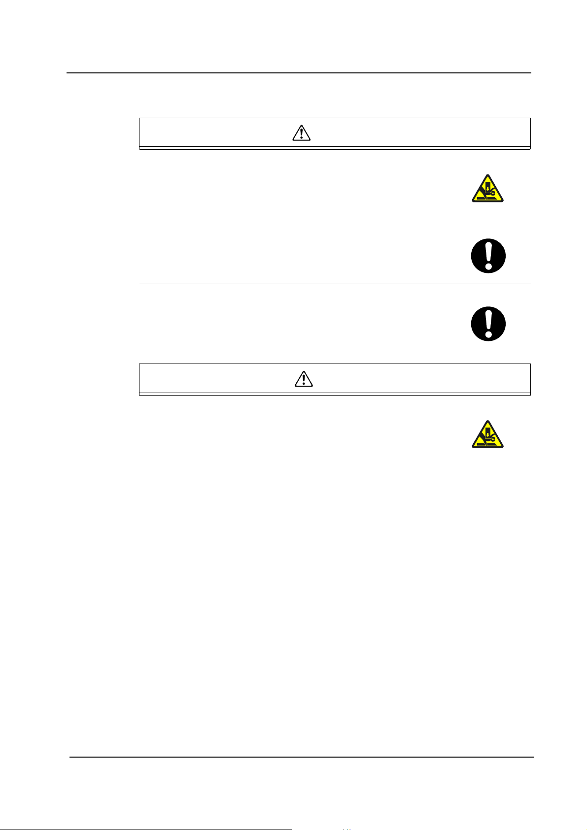
1. Safety Guideline QD002-07
1.3 Safety Rules for NXT
1.3.1 Main Unit
WARNING
Do not insert hands or other body parts into t he mach in e in t he
area between feeders especially when there are only a few
feeders present on the feeder pallet.
• Failure to do so could result in injury due to contact with the body
part and the head during movement.
When changing the conveyor width with the module retracted,
do not insert hands in the area near the conveyor
• Fing e rs may be pi nc ed or caug ht in the m ova b le co nve yo r ra il,
resulting in serious injury.
When mounting the MCU, ensure that no one is between the
MCU and machine base
• A person could be crushed to death if caught between the MCU and
base.
When pushing a module onto the base, check that no one is
behind the module
• A person could be crushed between the base and module, resulting
in serious injury.
When pushing in a module, do not insert hands between the
module cover support and module
• Fingers may be pinced or caught, resulting in serious injury.
When pushing in a module, do not insert hands between the
module lower front cover and base
• Fingers may be pinced or caught, resulting in serious injury.
When pulling out or pushing in a module, do not insert hands or
other body parts in between modules
• If caught between modules, fingers or other body parts could be cut
or severed.
When working on the module in an opening with the cover off,
ensure that no one pushes or pulls out in the module
• The module may punch, sever, or cause serious injury.
6 NXT Setup Manual
QD002-07 1. Safety Guideline
WARNING
When working on the base in the opening above the waste tape
box, ensure that no one pulls out a module
• The module may pinch, sever, or cause serious injury.
When working on the base in an opening with the cover off,
ensure that no one pushes or pulls out in the module
• The module may pinch, sever, or cause serious injury.
Do not rotate the module lock knob to [UNL OCK] when a module
is loaded on the MCU.
• If the module moves on the MCU, it could pinch and sever fingers,
and if it falls from the MCU it could cause severe injury or death.
There is a limit to the number of modules that can be pulled out
safely at the same time. (Maximum: Four M3 modules on an 8M
base, or two M3 modules on a 4M base.)
• If the maximum is exceeded, the entire machine may fall over to the
front, possibly resulting in serious physical harm. This is especially
true when the front leveling bolts have not been adjusted.
Do not modify the module stopper mechanism on the base and
remove the module without mounting the MCU first.
• The module could fall from the base causing severe injury or death.
Do not stare at the vision process light sources with naked eye s.
Wear protective glasses.
• Ey e da m ag e ma y be cau se d by the ligh t.
Stay off of the base.
• Failure to do so could result in injury.
When handling the MCU, watch out for corners and protrusions.
• Failure to do so could result in injury.
Always be ready to apply the caster brake when handling the
MCU.
• Always use the caster brake when stopping an MCU loaded with a
module.
NXT Setup Manual 7
1. Safety Guideline QD002-07
WARNING
When lifting a backup plate, be careful to not put your hands in
the areas between the plate, width-changing ball screw, and
hexagonal shaft. Also, be careful to not cut your hands on the
corners of the conveyor rails.
• Failure to do so could result in injury.
Do not lift a backup plate if you are not strong enough, and
maintain correct lifting posture if you do lift a backup plate.
• Because the backup plates are very heavy, lifting them incorrectly
could result in back or other injuries.
Never insert hands or other body parts into the duct of the waste
tape disposal unit.
• There is a very sharp cutter blade. Exercise extreme caution
especially when carrying the unit.
Two or more people should carry the waste tape disposal unit.
• Maintenance of the waste tape disposal unit is usually accompanied
by removing the unit from the machine. Two or more people should
carry the unit because it is very heavy.
Ensure that the work bench where the waste tape disposal unit
is placed is flat.
• The unit may fall to the ground if the work bench is tilted, causing
personnel injury and the machine damages.
Do not touch the Y-axis linear motor in a M6S module
immediately after production is stopped.
• Contact with the shaft or coil section could cause burns. The shaft
and coil section of the Y-axis linear motor remain at high
temperatures even after production is stopped.
People with a heart pacemaker should stay clear of the Y-axis.
• A heart pacemaker could malfunction due to the strong magnetic
field generated by the linear motor for the Y-axis in M6S modules.
Do not disassemble the linear motor used for the Y-axis in the
M6S module.
• Absolutely do not disassemble the linear motor coil and shaft parts.
Injury and/or machine damage may occur by magnetic parts
shooting out due to the strong force of the magnets.
8 NXT Setup Manual

QD002-07 1. Safety Guideline
CAUTION
Be careful to not pinch your hands when opening and closing
the front or side covers.
• Failure to do so could result in injury.
Do not insert fingers or other body parts into the gap between
the machine side cover and base.
• Failure to do so could result in injury.
When working in front of the base, ensure th at clothing or arms
are not caught on the guide pins on the top of the base to
prevent the risk of injury.
• Failure to do so could result in injury.
When there is no module on the b ase, do not block t he modu le
position confirmation sensor or module seating confirmation
sensor to activate the air cylinder.
• Air cylinder may activate to move lever or clamper causing
personnel injury.
Do not push the mark camera unit by hand when moving the
placing head.
• The position of the mark camera may be shifted, which negatively
affects the placing accuracy of the machine.
Be careful to not put your hands underneath the nozzle st ation
when loading it in the machine.
• Failure to do so could result in injury.
Ensure to place the waste tape disposal unit with the duct
upside on the work bench.
• The duct of the unit may creep by its own weight.
Be careful of the magnetic attraction when using a jig near the
linear motor of the M6S.
• Injury could result by a jig being drawn towards the linear motor.
Keep magnetic cards, wristwatches and other precision
machines away from the linear motor of a M6S module.
• Damage to items may occur due to the magnetic field generated by
a linear motor.
NXT Setup Manual 9
1. Safety Guideline QD002-07
1.3.2 Tray Unit-L
WARNING
When pushing the tray unit-L into the machine, ensure that no
one is between the tray unit-L and machine base.
• A person could be seriously injured or crushed to death if caught
between the tray unit-L and machine.
Lock the caster brake whenever the tra y unit-L is removed from
the machine.
• Depending on the slope and condition of the floor, the tray unit-L
could roll unexpectedly, possibly resulting in injury.
CAUTION
Be careful to not pinch your fingers when opening or closing
the tray unit-L covers (upper cover, front cover, lower cover,
etc.). Do not leave the doors open while the tray unit-L is
unattended.
• Failure to do so could result in injury.
When operating the handle for adjusting the tray unit-L height,
make sure that hands are not caught between the handle and
cover.
• Failure to do so could result in injury.
When removing or replacing the empty tray box, be careful to
not pinch your hands between the tray unit-L and empty tray
box.
• Failure to do so could result in injury.
Do not insert your hand through the bottom of the tray unit-L
into the inner section where the mechanical parts are.
• Failure to do so could result in injury.
10 NXT Setup Manual
QD002-07 1. Safety Guideline
1.3.3 Tray Unit-M
WARNING
Do not insert hands or other body parts in the space between
the tray unit-M and the feeder pallet when at taching or removing
the tray unit-M.
• Failure to do so could result in injury.
Use two or more people to lift, carry and position t he tray unit-M.
• The tray unit-M is extremely heavy and injury could result if
dropped.
Do not insert hands or other body parts in the side spaces
between the machine and the tray unit-M during automatic
operation.
• Body parts may be pinched or caught, resulting in injury.
CAUTION
Be careful to not pinch or get body parts caught on the tray unitM door when opening and closing it. Ensure that the door is
never left open.
• Body parts may be pinched or caught, resulting in injury.
NXT Setup Manual 11
1. Safety Guideline QD002-07
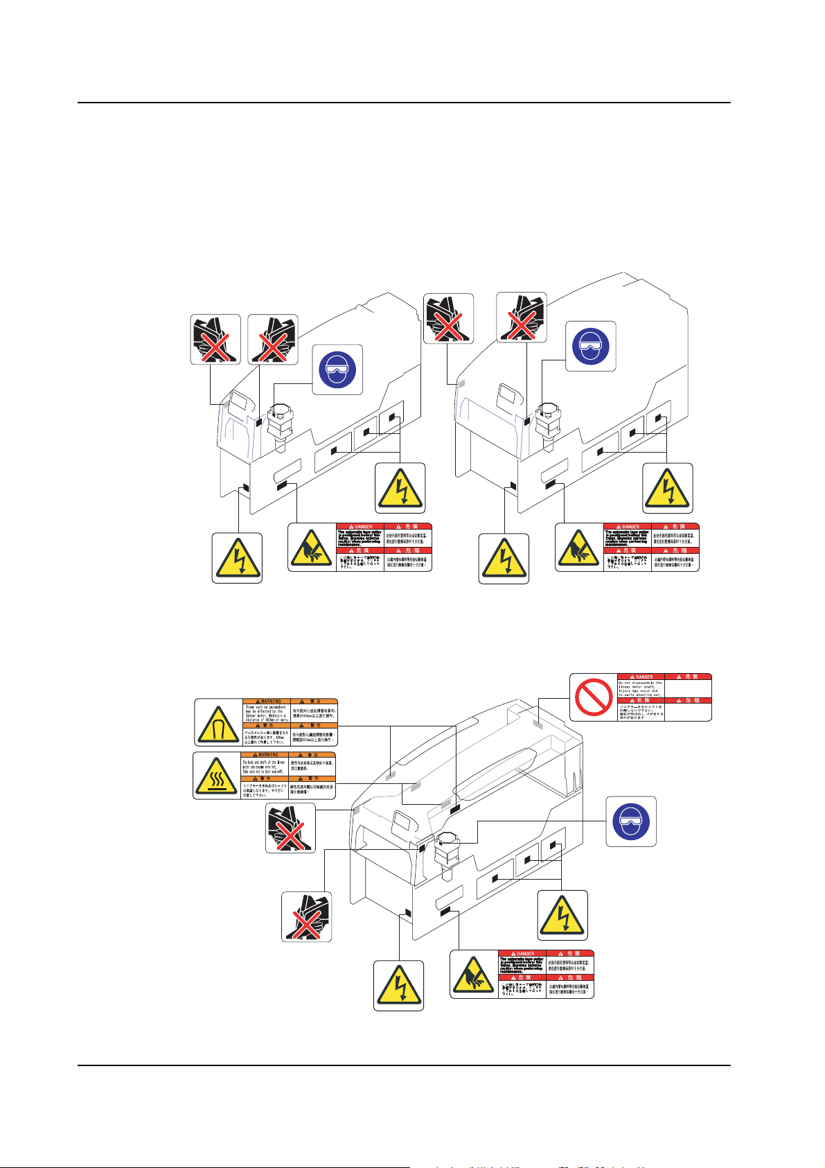
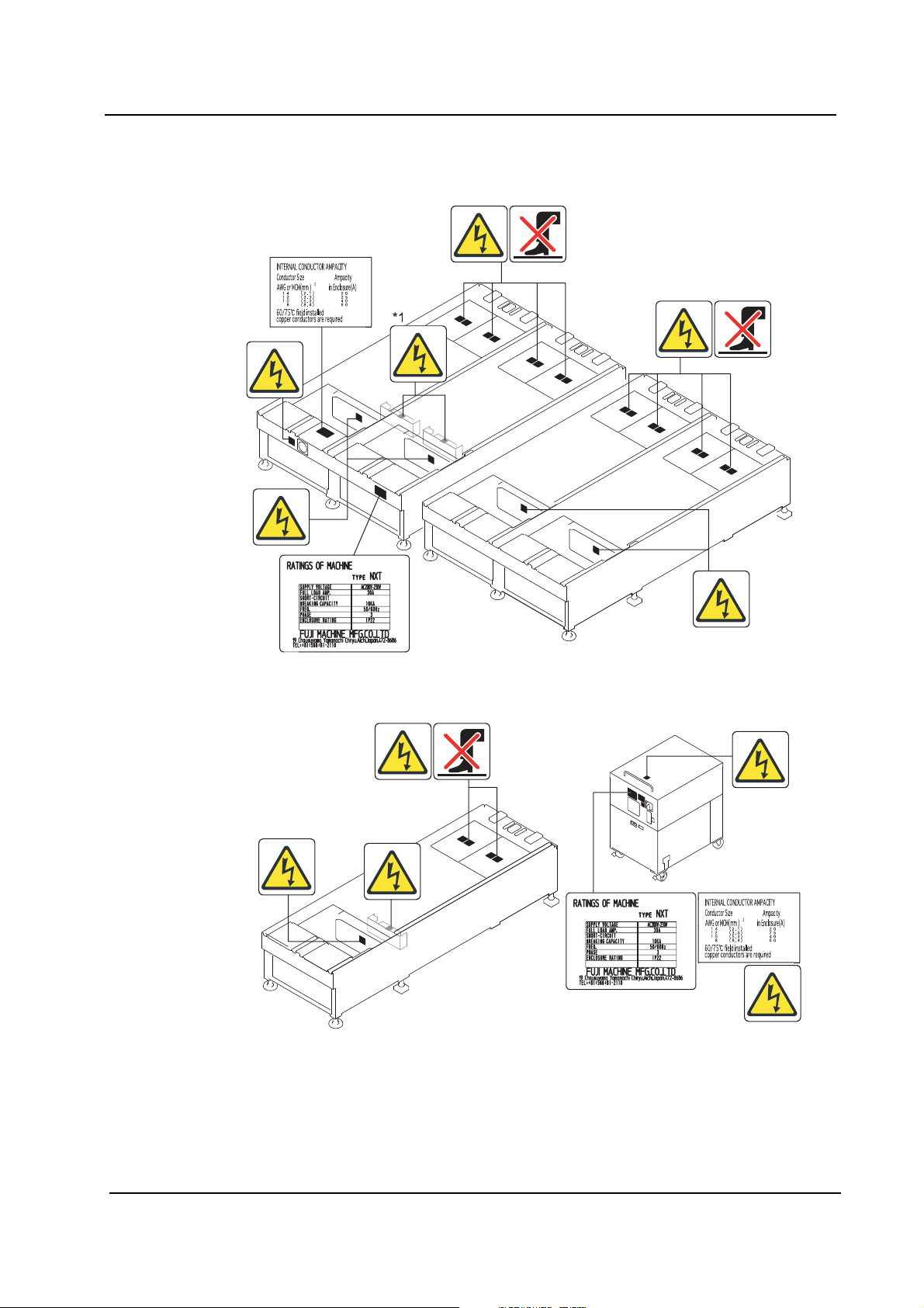
1.4 Safety Labels
To warn the operator of hazards, safety labels are attach ed to the machine at the positions
indicated in the figure below.
Familiarize yourself with each label and its message before operating the machine.
M3(S) Module M6 Module
*1
M6S Module
*1
*1
*1
Зл²»Тª½шРРПЯРФµз¶¯»ъµДЦбµД·Ц½в¡£
´жФЪ´ЕК¯·Й³ц£ ¬µ¼ЦВКЬЙ ЛµДО£ПХ ¡£
½Ð¤£-n¶ i¦æ½u©Ê¹q˚ ʾ÷ªº¶bªº¤À¸ Ñ¡C
¦s¦bºÏ¥Û-¸¥X¡A¾É-P¨ü¶Ëªº¦MÀI¡C
*1
*1
NXTSAF010Eb
12 NXT Setup Manual
QD002-07 1. Safety Guideline
4M base
*
*1
*1
*1
*1
2M base
*1
*1
*1
Dependent 4M base
*1
*2
NXTSAF011E
NXT Setup Manual 13

1. Safety Guideline QD002-07
MSU
WARNING
⼊ ๔
Engineering panel stand
Tray unit-M
Tray unit-L
*1
Side cover
*1
NXTSAF012Ea
14 NXT Setup Manual
QD002-07 1. Safety Guideline
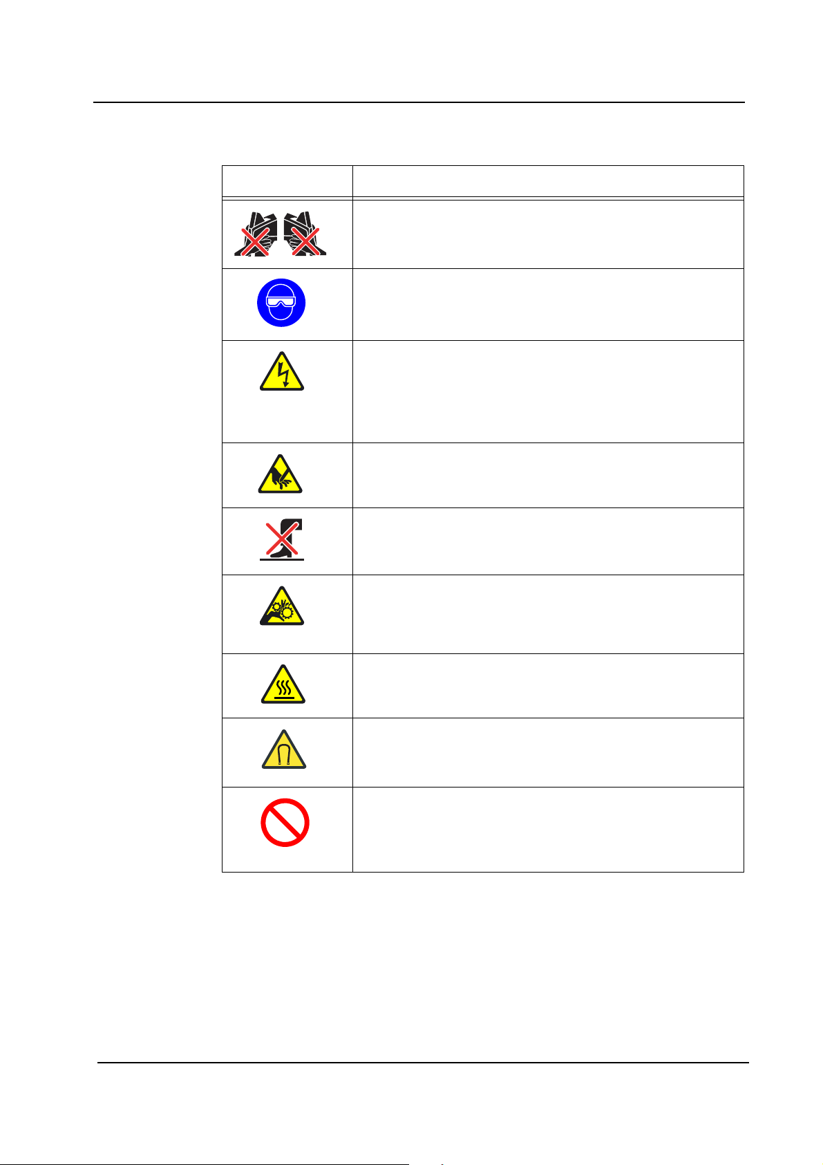
1.4.1 NXT Safety Label Explanations Symbol Explanation
Warning: Pinching danger
Do not insert hands or other body parts in the spa ce betwee n
adjacent modules.
Mandatory action, Direction: Eye protection
Direct exposure to the lighting unit may result in damage to the
eyes. Ensure to use light protection eyewear when necessary.
Caution, Warning: Shock danger
*1: High voltage! Contact may cause electric shock. Turn off
the power prior to servicing.
*2: Connect a 200 - 230V AC +/-10% 50/60Hz primar y po wer
supply to the machine.
Caution, Warning: Cutting danger
An automatic tape cutter is positioned behind this frame.
Exercise extreme caution when performing maintenance.
Warning: Do not step
Do not step or stand on this area.
Caution, Warning: Moving parts
Do not insert hands or other body parts.
Moving parts may cause injury. Turn off the power before
inserting any body parts.
Warning: High Temperature
Contacting with the main body and shaft of the linear motor
could result in burns. They are high temperature.
Warning: Magnetic Field
Heart pacemakers and other precision equipment could be
affected by the magnetic field. Always keep a distance of 400
mm or more.
Warning: Disassembly prohibited
Do not disassemble the linear motor shaft. Injury may occur
by parts shooting out due to the strong force of the magnets.
NXT Setup Manual 15
1. Safety Guideline QD002-07
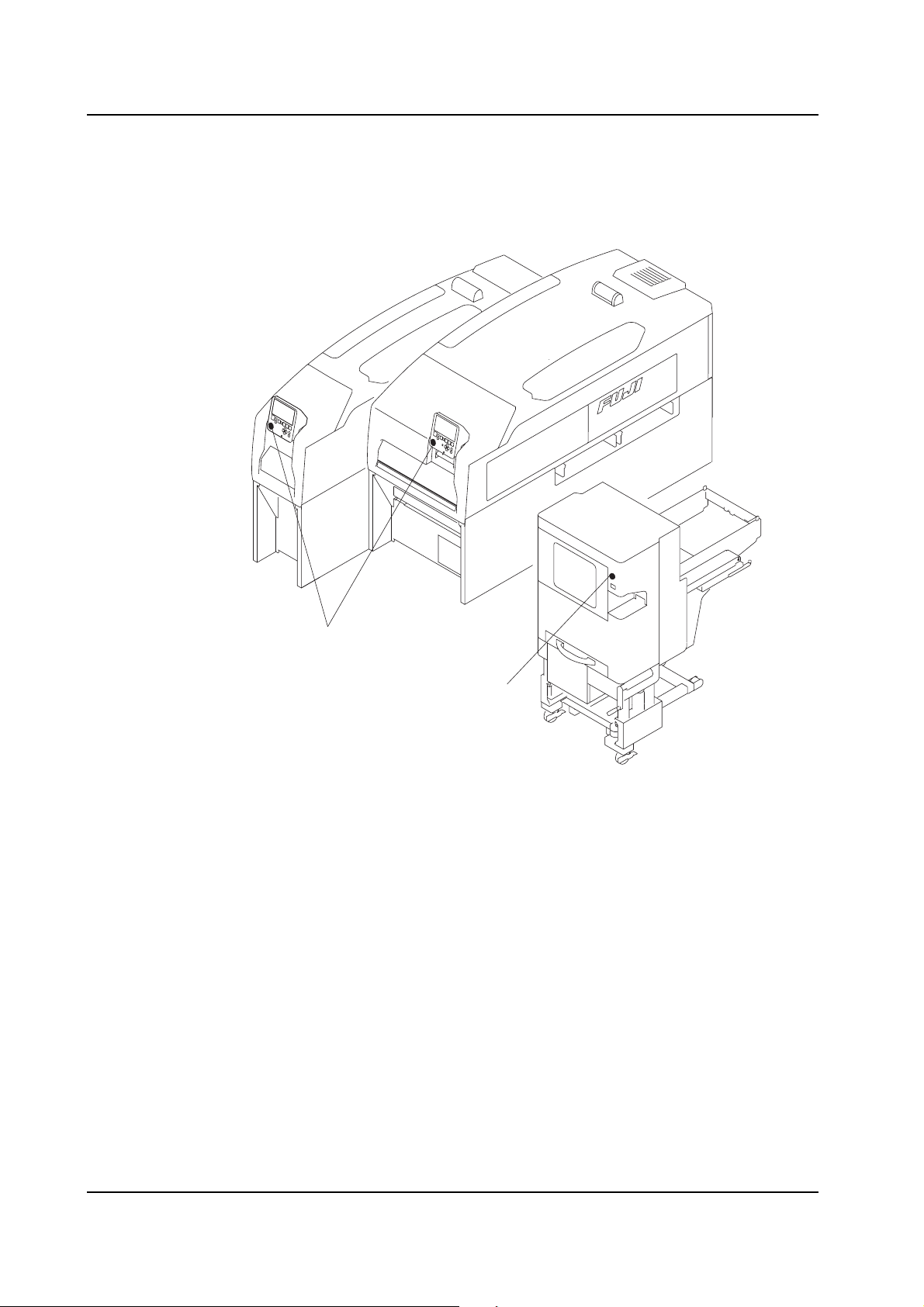
1.5 The EMERGENCY STOP Button
In the event of an emergency, press any of the red EMERGENCY STOP buttons located
on the machine at the positions indicated in the figure below.
EMERGENCY STOP buttons
EMERGENCY STOP button
NXTSAF001Eb
16 NXT Setup Manual
QD002-07 1. Safety Guideline
1.6 Locking System
When performing maintenance or service on the machine, all personnel who service the
machine should use locks to prevent others from turning on the machine power or air. This
procedure is referred to as a lockout.
To prevent accidents, especially those caused by mistakes when multiple operators are
present, all related personnel should have thorough knowledge of lockout procedures.
1.6.1 Lockout Procedure
Prepare 2 commercially available padlocks, and require all service personnel to carry
lockout nametags.
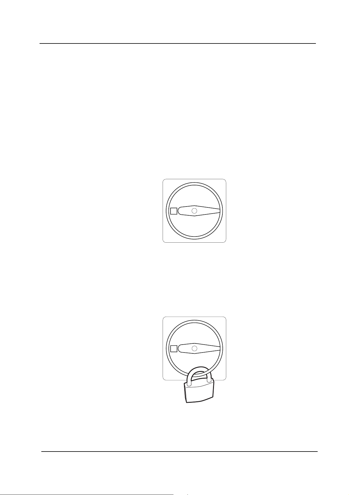
1. Switch off the machine power.
2. Rotate the main switch on the base to the OFF position.
0
NXTSAF004
3. Lock the main switch with a padlock.
All personnel working on the machine should attach their lockout nametags to the
padlock.
Note: Note:The presence of a nametag on the padlock signals that the machine is being serviced and that the
lock is not to be removed.
0
NXTSAF006
NXT Setup Manual 17
1. Safety Guideline QD002-07
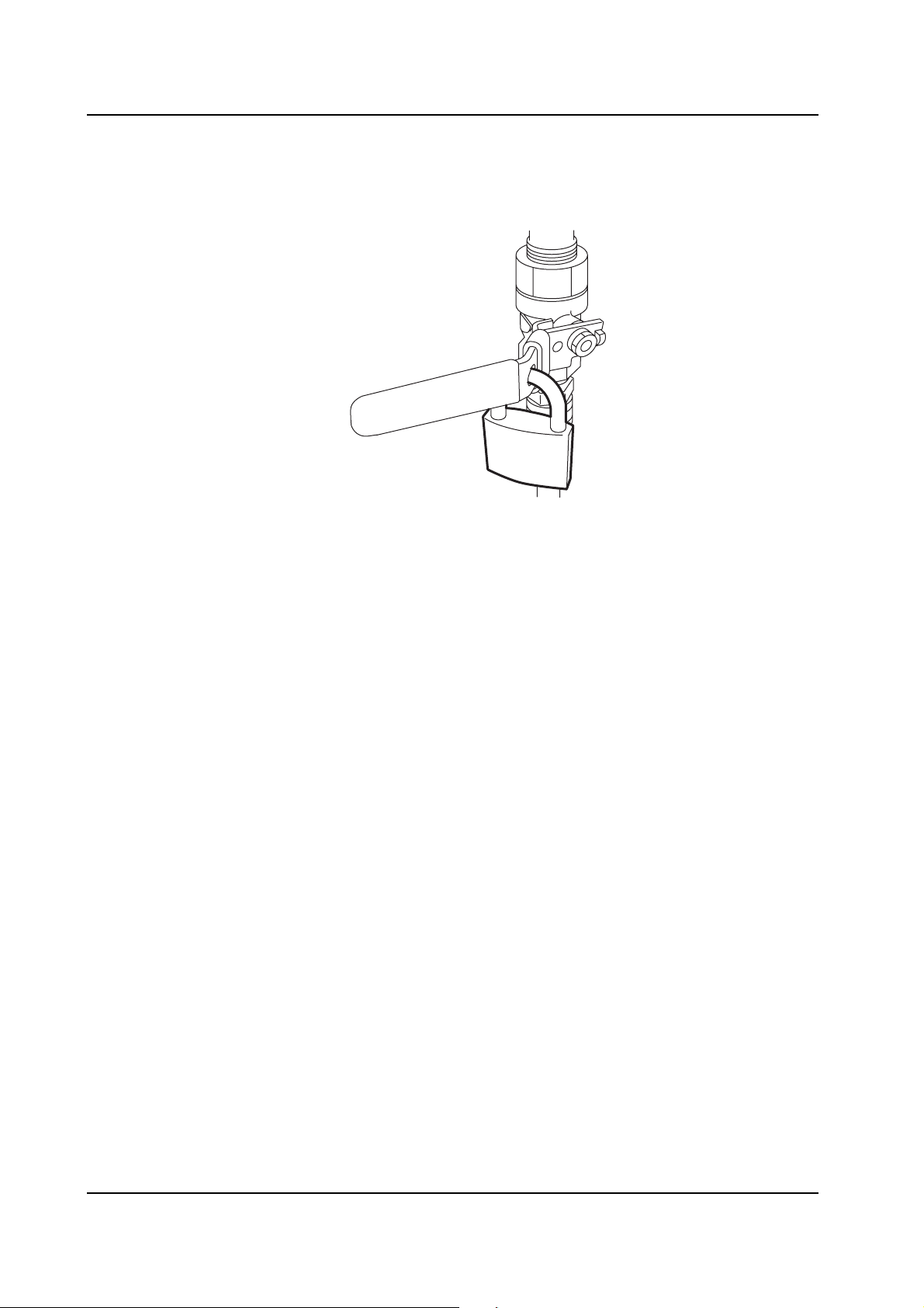
4. In the same manner, rotate the air valve handle to the OFF position and lock with the
second padlock.
All personnel working on the machine should attach their nametags to the padlock.
NXTSAF005
5. The lockout is complete.
18 NXT Setup Manual
QD002-07 1. Safety Guideline
1.6.2 Unlocking Procedure
When finished servicing the machine, all personnel should r emove their lo ckout nametags
from the padlocks.
1. Confirm that all personnel are clear of the mac hin e.
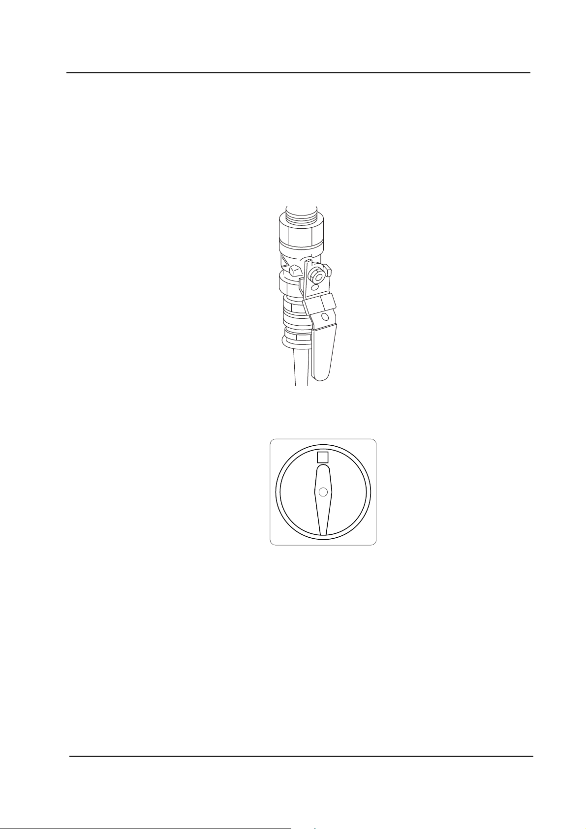
2. Confirm that the machine is in a safe condition. Remove the padlock from the air valve
and rotate the handle to the ON position.
NXTSAF007
3. Remove the padlock from the main switch and rotate it to the ON position.
1
NXTSAF008
4. This concludes the unlocking procedure.
NXT Setup Manual 19

1. Safety Guideline QD002-07
MEMO:
20 NXT Setup Manual
QD002-07 2. Setting Up the NXT
2. Setting Up the NXT
2.1 Introduction
The aim of this manual is to provide procedural explanations of how set up the NXT
machine. The procedures outlined are to help an NXT user perform the various
mechanical, and software related operations necessary to set up the NXT for use.
The order of the procedures in this manual are basically in the order that they should be
performed for the easiest set up. In all cases, not all procedures (such as setting the IP
address of the base) need to be performed, especially when just moving the machine/base
within the factory. Refer to the table below for an outline of the setup process.
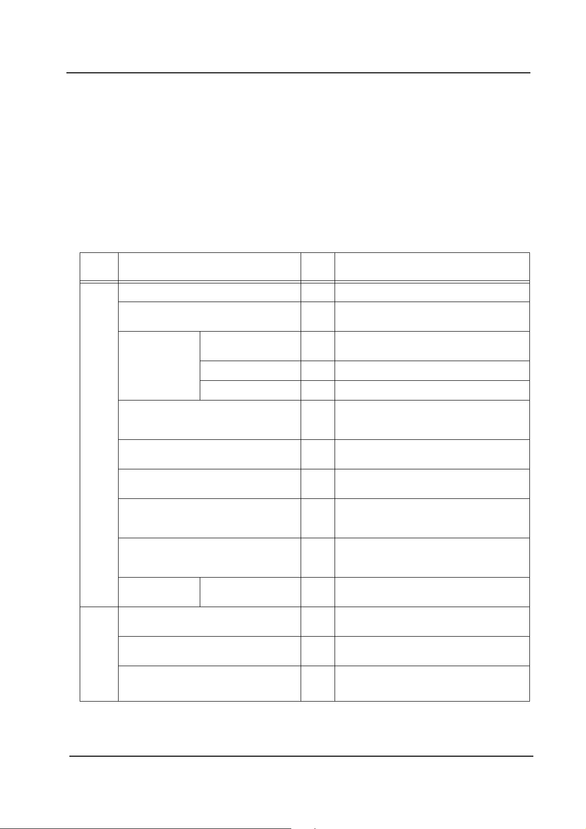
Chap
ter
3. Machine Set Up
Section Ord. Step
Moving a Machine 1 Move the machine to the desired location.
Removing Fixing Brackets 2 Remove the brackets used to fixed the
axes during transport.
Making Basic
Connections
Leveling the Machine 6 Level the machine and ensure that the
Making Network Settings 7 Specify the IP address and other network
Connecting NXT Bases 8* Connect the communication cables
Installing Additional Dependent Bases 8* Connect the communication cables and
Electric Power
Supply
Network Cable 4 Connect the network cable to the base.
Air Supply 5 Connect the air supply to the base.
3 Connect the power cable to the base.
conveyor height matches that of the other
machines in the line.
related settings for the set up base.
between the NXT bases.
the pneumatic tubes between the NXT
bases. Fix the bases with brackets.
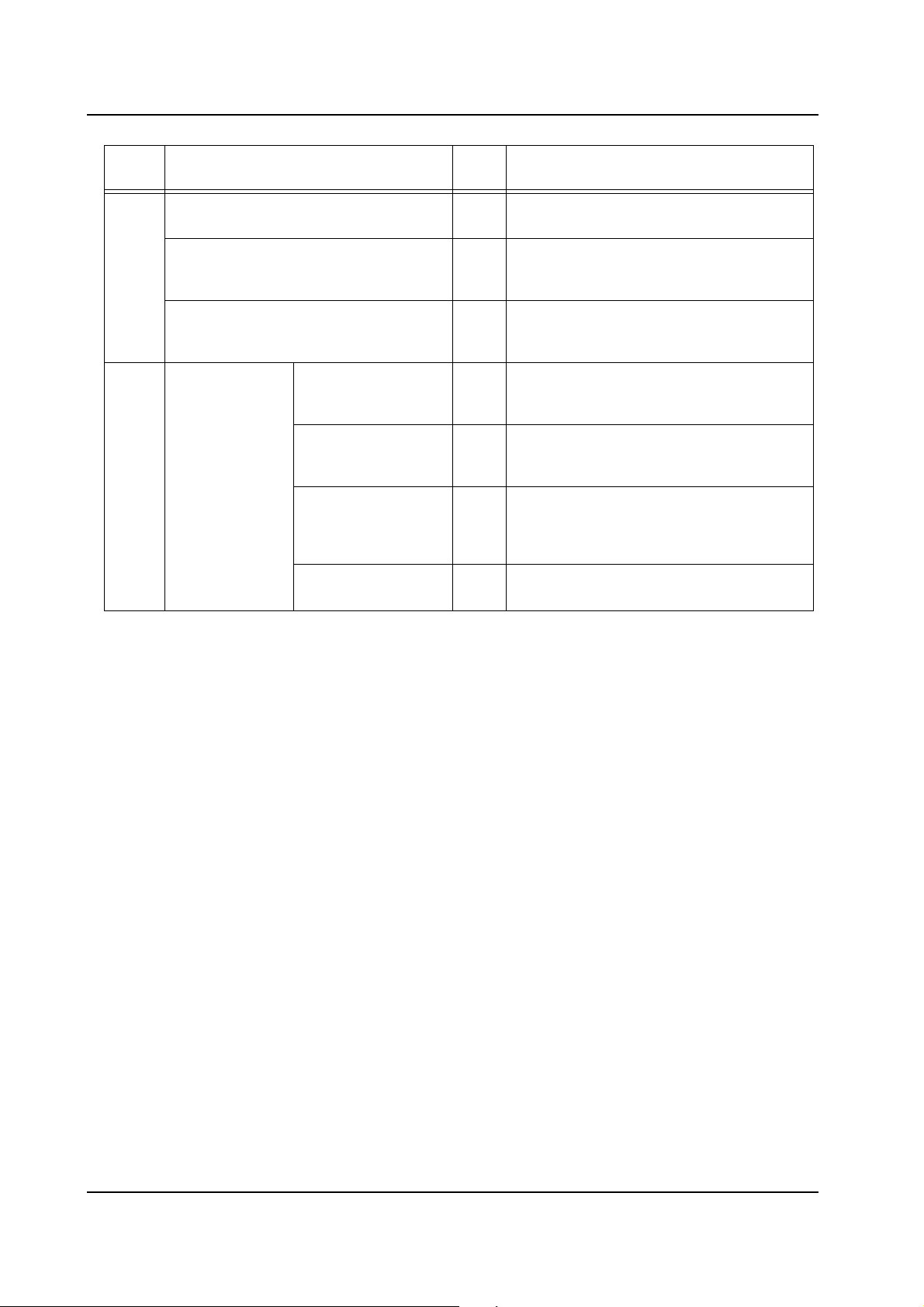
Connecting an NXT Base to Other
Machine Types
Tray Unit-L Adjusting the height
Creating a factory 10 Create a factory in the Fuji Flexa line
Creating a line 11 Create a line in the Fuji Flexa line
Creating a machine 12 Create the NXT machine in the desired
4. Setting Up NXT
Machines in Flexa
and levelness
8* Connect the communication cables
between the NXT base and neighboring
machines other than NXT bases.
9 Use a level gauge to adjust the height and
levelness.
configuration, if necessary.
configuration, if necessary.
line in the Fuji Flexa line configuration.
NXT Setup Manual 21
2. Setting Up the NXT QD002-07
Chap
ter
Software
5. Accessory
6. Setting Up Fujitrax Verifier
Section Ord. Step
Required Items 13 Ensure that the necessary items to install
Installing Fuji Flexa 14 Install Fuji Flexa on the computer that
Installation
Installing NXT Accessory Software 15 Install the Accessory Software on the
Required Items Installing and
running the Central
Server
Adding the NXT to
the Fujitrax line
configuration
Setting the NXT
Fujitrax
configuration
settings
Registering users
for Kit Handy access
16** Ensure that the Central Server for Fujitrax
17** Add the NXT machine to the line
18** Change the Fujitrax configuration settings
19** Register the ID for the users that are to
Accessory Software are available.
Accessory Software is to be installed, if it is
not already installed.
computer that is to act as the Accessory
Software server.
Verifier has been installed and is running.
configuration for the Kit Server that is to be
used for the NXT.
on the NXT.
access NXT data through Kit Handy.
Note: * Perform the items required based on the line composition.
** These steps are only necessary if Fujitrax Verifier is to be used.
22 NXT Setup Manual
 Loading...