

FujiFilm GTX User Manual

CONTENTS
Contents . . . . . . . . . . . . . . . . . . . . . . . . . 1
Safety Precautions . . . . . . . . . . . . . . . . . 2
Air Control Valve & Diaphragm . . . . . . . 3
Spray p attern . . . . . . . . . . . . . . . . . . . . . . 4
Fan size . . . . . . . . . . . . . . . . . . . . . . . . . . 5
Spraying techniques . . . . . . . . . . . . . . . . 6
Aircap selection . . . . . . . . . . . . . . . . . . . 7
Latex & Viscosity . . . . . . . . . . . . . . . .8 - 9
Viscosity guide . . . . . . . . . . . . . . . . . . . . 9
Cleaning . . . . . . . . . . . . . . . . . . . . . . . 9 -10
Pressure pot use . . . . . . . . . . . . . . . . . .10
Finish Problems . . . . . . . . . . . . . . . . . . 11
Spray Gun Problems . . . . . . . . . . . . . 12 -13
Needle Packing & Seals. . . . . . . . . . . . 14
Parts disassembly . .. . . . . . . . . . . . . . . 15
Turbine problems . . . . . . . . . . . . . . . . . 15
Parts diagrams. . . . . . . . . . . . . . . . . . 16 -18
Gravity Spray Gun. . . . . . . . . . . . . . 18
Service information. . . . . . . . . . . . . . . . 19
Warranty information . . . . . . . . . . . . . . 20
CE Declaration . . . . . . . . . . . Back Cover
20
1
Limited 2 Y ear W arranty
Fuji Industrial Spray Equipment Ltd. issues a 24
month limited warranty to the purchaser effective from
the date of purchase against defects in materials or
workmanship. This warranty does not cover abuse,
accidental damage, misuse, normal wear parts, motor
brush replacement, or spray gun maintenance and
clean-up. W arranty is void if repairs are made or
attempted by unauthorized persons. At our option,
Fuji Spray will repair or replace defective parts
without charge provided the purchaser return parts
prepaid to the nearest authorized service center or to
the factory.
Factory returns must first receive a Return Material
Authorization. In North America, please call 800650-0930 to obtain an authorization number. In other
countries, please call the company where you purchased the product.
This unit is designed to be used for spray painting and
similar operations only. Fuji will not be held liable if
equipment is not used solely for the purpose it was
designed. W arranty will become void through improper installation or operation. Any modifications to
the equipment or deviations from recommended
procedures, accidental damage or any related action
that impairs or abuses normal wear and care of Fuji
spray equipment will also void warranty and liability .

19
Please read these instructions carefully before using the equipment
ELECTRICAL
The turbine is powered by a 3-stage or 4-stage (depending on the model)
single speed, bypass, air turbine. This turbine must be connected to the
correct voltage. Please check the label on the base for voltage rating.
ELECTRICAL CONNECTION
For your safety and protection, we have equipped your Fuji turbine with a
three-pronged grounding plug on the service cord. This must be plugged
into a properly grounded 3-pronged receptacle. (For some countries this
may be a 2-pin grounded plug).
SAFETY WARNINGS:
THE TURBINE MUST NOT BE USED IN AN AREA CONTAMINA TED BY
VOLATILE OR FLAMMABLE MA TERIALS SINCE SP ARKING CAN BE
EXPECTED IN THE NORMAL OPERATION OF THE MOT OR. THIS COULD
IGNITE THE CONTAMINANTS CAUSING A DANGEROUS EXPLOSION. KEEP
THE TURBINE A T LEAST 18 FEET (5.5 METERS) A WA Y FROM THE SPRA Y ING AREA. FOR HEALTH REASONS, ALWA YS WEAR A RESPIRATOR.
PLEASE CHECK WITH THE LOCAL JURISDICTION.
THE SPRAYGUN MUST NEVER BE POINTED A T SOMEONE’S FACE.
THE OPERATOR MUST WEAR SHOES AND THE FLOOR MUST NOT BE
WET.
FILTER(S)
The Q-PRO Series turbines use just ONE large filter. The turbine case
does not need to be taken apart to replace the filter. To remove, simply
turn the turbine on its side and pull the filter out. Wash in solvent and dry
before replacing. All Fuji filters are a friction fit. When replacing, push the
filter in by hand and finish up by using a screwdriver through the square
holes to lever the filter into position. The filter must fill the entire filter
enclosure and always be FLUSH with the base of the turbine case.The
Mini-Mite Turbines use 2 filters, one fine and one coarse. Looking from the
front of the turbine please insert the fine filter to the left side (near the ‘F’ of
Fuji) and the coarse to the right side. It is important to keep the turbine as
far away as possible from the spraying area (and workshop dust). If the
filters become badly clogged, cooling air will be restricted - this may cause
serious damage to the motor. THE TURBINE MUST BE PLACED ON THE
FLOOR - NOT UP HIGH. THIS IS BECAUSE THE BEND IN THE HOSE CAUSES
BACK PRESSURE INTO THE MOTOR.
2
For SERVICE & PARTS
USA
Fuji Spray
Phone: 800-650-0930 Online: www.hvlp.net
Phelps Refinishing
Phone: 800-377-5662 Online: www.phelpsrefinishing.net
UNITED KINGDOM
Axminster Power Tool Centre. Axminster, Devon, England
Phone: 01297 33656
Rutlands Limited. Bakewell, Derbyshire, England
Phone: 01629 815518
EUROPE
Larius SRL. (Lecco), Italy
Phone: 0341-621152
Aerometal. S.A. Spain/Portugal
Phone: 34-935620212
AUSTRALIA & NZ
apSM Tecni Pty Ltd. Campbellfield, Victoria 3061
Phone: 3-9359-5000
PUERTO RICO
Eagle Tools Mfg. Corp San Lorenzo, Puerto Rico, 00754
Phone: 787-736-0444
SOUTH KOREA
E-Woo Painting Technology . Seoul, Korea
Phone: 82-2-2103-1477 Fax: 82-2-2103-1488
Copyright © 2008 Fuji Industrial Spray Equipment Ltd. T oronto. Canada
3
18
AIR CONTROL VA LVE
The air control valve 2032 is located on the hose next to the brass quickconnect. It provides you with a means of controlling the air flow through the
gun. It offers you fingertip control when you need it to reduce bounceback
and overspray. There is one thing to remember about the air control valve - it
is the ‘last in the chain’ of operations after...
1) Thinning the paint
2) Adjusting the shape and size of the spray pattern
3) Adjusting the flow of paint through the gun.
After performing these operations, you should spray a few passes onto a
scrap piece of plywood or cardboard. This will allow you to determine if the
paint (generic word for any type of coating) levels nicely. If there is ‘orangepeel’ then you must thin the product more. Once the gun is producing a
perfect finish with full air, you may then experiment with turning the air down
until bounceback is reduced to a mininum. However, if orange-peel results,
you have no option but to turn the air up again a slight amount. With heavier
paints (such as latex) spraying may be done with the valve fully open (or even
removed). When excessive ‘bounceback’ or overspray is a problem, turn the
lever to reduce the amount of air.
PLASTIC DIAPHRAGM - XT-2 MODEL
The XT 1 Quart pressurized cup (not found in the Gravity Spraygun) has a
plastic diaphragm 2038. This diaphragm prevents paint from entering the
pressure tube 2024. The small air hole in the diaphragm should not be
placed directy below the air hole in the nipple. Position the diaphragm hole
to the rear of the cup. The spraygun can be turned to different angles when
spraying, however the cup should never be higher than the gun (above
horizontal). To remove the diaphragm for cleaning, grab the small tab and
slide it gently down the metal fluid tube. The diaphragm can be washed in
thinner. Note: There is no diaphragm on the Fuji GT-X Gravity Spraygun.
GETTING STARTED
Your Fuji Spraygun has been adjusted at the factory and is ready for spraying.
To clean out any impurities that may have accumulated during assembly or
shipping, we recommend spraying a small quantity of clean paint thinner
through the gun. Before tackling any serious spraying, experiment using
plain water until you become familiar with all the controls.
HOSE CONNECTION
Connect the end of the hose (female connector) to the turbine air outlet.
ALW A YS TURN OFF THE TURBINE BEFORE DISCONNECTING THE GUN FROM
THE HOSE. This prevents unequal pressure in the cup forcing paint up the
pressure tube.
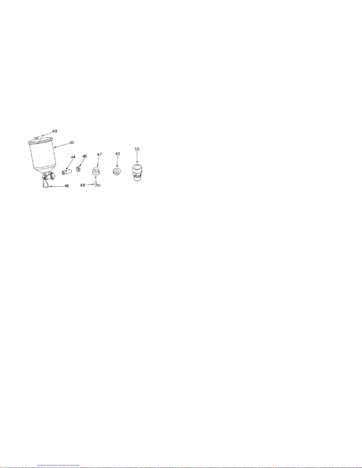
GTX Gravity Gun (Accessory)
ITEM PART NAME ITEM PART NUMBER
43 9850 Gravity Cup 47 2020 Nipple Adaptor
44 9051 Fluid Coupler 48 2021 Nipple
45 8067 Jamb Nut 49 8010 Air Plug
46 0000 Stand 50 8065 Hose Connector
The new GT-X Gravity Gun now offers the choice between pressurized or
non-pressurized use – here’s how…
PRESSURIZED CUP
The GTX spraygun is already setup to spray using the pressurized Gravity
Cup. This is more suited to heavier paints such as Latex House Paint
(Emulsion) and will also provide for faster coverage. But for a softer spray,
you may want to try experimenting with a ‘non-pressurized cup’.
Non-Pressurized Cup:
1) Remove the Pressure Tube from the 2021 Nipple on the Lid of
the Cup
2) Unscrew the 2020 Nipple Adaptor (located under the front barrel
of the gun).
3) Replace the 2020 Nipple Adaptor wiht thethe 8010 Air Plug
(Supplied) to block the hole.
You can now spray with a non-pressurized Gravity Cup. This is more
suited to thinner (less viscous) liquids. Coverage will be slower than with
the pressurized cup.
 Loading...