

FUJIFILM FinePix S2 PRO SERVICE MANUAL
DIGITAL CAMERA
FinePix S2 Pro
SERVICE MANUAL
U/E-Model
WARNING
THE COMPORNENTS IDENTIFIED BY THE MARK “ ” ON THE SCHEMATHIC
DIAGRAM AND IN THE PARTS LIST ARE CRITICAL FOR SAFETY.
PLEASE REPLACE ONLY BY THE COMPORNENTS SPECIFIED ON THE SCHMATHIC
DIAGRAMAND IN THE PARTS LIST.
IF YOU USE WITH PART NUMBER UN-SPECIFIED, IT MAY RESULT IN A FIRE AND AN
ELECTORICAL SHOCK.
Ref.No.:ZM00438-105
FUJI PHOTO FILM CO.,LTD.
Printed in Japan 2002.06(T.S.)
SAFETY CHECK-OUT
After correcting the original problem, perform the following safety
check before returning the product to the customer.
FinePix S2 Pro (U/E) SERVICE MANUAL
1. Check the area of your repair for unsoldered or poorly
sol dered connections. Check the entire board sur
face for solder splasher and bridges.
2. Check the interboard wiring to ensure that no wires
are “pinched” or contact high-wattage resistors.
3. Look for unauthorized replacement parts, particu
larly tran sistors, that were installed during a previ
ous repair. Point them out to the customer and rec
ommend their replacement.
4. Look for parts which, though functioning, show obvi
ous signs of deterioration. Point them out to the cus
tomer and recommend their replacement.
5. Check the B + voltage to see it is at the values specified.
6. Make leakage - current measurements to determine
that exposed parts are acceptably insulated from the
supply circuit before returning the product to the customer.
7. CAUTION: FOR CONTINUED
PROTECTION AGAINST FIRE
HAZARD, REPLACE ONLY WITH
SAME TYPE 2.5 AMPERES 125V
FUSE.
2.5A125V
2.5A125V
8.
RISK OF FIREREPLACE FUSE
AS MARKED
WARNING!
HIGH VOLTAGE
ATTENTION: AFIN D'ASSURER
UNE PROTECTION
PERMANENTE CONTRE LES
RISQUES D'INCENDIE,
REMPLACER UNIQUEMENT
PAR UN FUSIBLE DE MEME,
TYPE 2.5 AMPERES, 125
VOLTS.
WARNING:
TO REDUCE THE ELECTRIC
SHOCK, BE CAREFUL TO
TOUCH THE PARTS.

FinePix S2 Pro (U/E) SERVICE MANUAL
CONTENTS
Table of Contents
1. General
1-1.Product Specifications ..................................................... 4
1-2.Camera Features .............................................................. 7
1-3.Names of External Components ..................................... 8
2. Disassembly
2-1.Names of internal Components ...................................... 10
2-2.Removing BATT CART ASSY .........................................11
2-3.Removing FRONT CABI ..................................................... 11
2-4.Removing DSC BLOCK ................................................... 12
2-5.Removing MAIN PWB ASSY...........................................13
2-6.Removing BATT HOLDER ASSY ................................... 14
2-7.Removing LCD MONITOR............................................... 14
2-8.Removing REAR DISPLAY PANEL................................15
2-9.Removing SW PWB ASSY .............................................. 15
2-10.Removing CCD HOLDER ASSY...................................16
2-11.Removing PLATE BOTTOM.......................................... 17
2-12.Removing GRIP BASE................................................... 17
2-13.Removing TOP COVER UNIT....................................... 18
2-14.Removing BODY FPC HARNESS ................................20
2-15.Removing SB LOWER CASE UNIT ............................. 20
3. Schematic
3-1.Cautions............................................................................. 22
3-2.Basic block name and function explanation.................. 22
3-3.Description of the Main Block Functions .......................22
3-3-1.Overview of the New Technologies ..................... 22
3-3-2.Block Functions Descriptions ............................... 23
3-3-3.Description of the Power Supply Block Functions .... 23
3-3-4.Description of the camera body block functions ....... 23
3-4.Basic block diagram ......................................................... 24
3-5.Overall Connections.........................................................25
3-6.Board mounting diagram ................................................. 26
3-6-1.Printed wiring board of MAIN PWB ASSY .......... 26
3-6-2.Printed wiring board of SW PWB ASSY ............ 27
4. Adjustment
4-1.Checklist for Major Component Replacement .............. 28
4-2.
Adjustment Sequence for Major Component Replacement ..
4-3.Measuring Instruments Used ..........................................29
4-4.Jigs Used ........................................................................... 29
[Modification of an inspection Lens to an adjustment Lens] ....... 30
4-5.Jig Connection ..................................................................31
4-6.Environment Settings ....................................................... 31
4-7.Various downloading software decompressions,
preservation methods, and notes .................................. 32
4-8.Install the DSC jig driver and the PC adjustment
software ............................................................................ 34
4-9.Adjustment Software Initial Setup ..................................35
4-10.Starting the Adjustment Software ................................. 37
Page
28
4-11.[F4]: CCD Defect Correction Adjustment ...................38
4-12.[F5]: CAM Adjustment....................................................40
4-13.[F1]: Battery Voltage Adjustment Adjustment............. 42
4-14.[F11]:REAR DISPLAY PANEL Adjustment .................. 44
4-15.[F7]: Flash Adjustment................................................... 45
4-16.[F6]: AF Adjustment ....................................................... 46
4-17.[F8]: Downloading Firmware .........................................51
4-18.[F12]: End Setting ........................................................... 53
4-19.Specifying the CAMERA BODY Setting When
Requesting Nikon Repairs .............................................. 57
5. Inspection
5-1.Measuring Instruments and Jigs Used for Inspection.......... 60
5-2.Connection of Measuring Instruments for Inspection .......... 60
5-3.Inspection and Settings at Shipment .............................60
5-4.Resolution Checking ........................................................64
5-5.CCD Cleaning and Inspection Procedures .................... 65
5-5-1.
CCD Cleaning Using a Visual Inspection for Dusting ....
5-5-2.
CCD Cleaning Using Test Photography to Detect Dusting
5-6.AF Checking......................................................................67
5-6-1.Measuring equipment and tools used for AF checking ...... 67
5-6-2.Settings for the measuring equipment and tools
used for AF checking ............................................67
5-6-3.AF testing procedure ............................................. 68
5-6-4.Cause identification procedure for focus-related
problems ................................................................. 69
6. Parts List
6-1. U-Model ............................................................................ 70
6-1-1. Packing and Accessories (U) .............................. 70
6-1-2.CAMERA BODY (U) ..............................................71
6-1-3. Cabinet R (U)........................................................72
6-1-4. Internal (U) ............................................................ 73
6-1-5. TOP COVER (1) (U)............................................. 74
6-1-6. TOP COVER (2) (U)............................................. 75
6-1-7. CAMERA BODY External (U) ............................. 76
6-2. E-Model ............................................................................. 77
6-2-1. Packing and Accessories (E).............................. 77
6-2-2.CAMERA BODY (E) .............................................. 78
6-2-3. Cabinet R (E) ........................................................ 79
6-2-4. Internal (E) ............................................................80
6-2-5. TOP COVER (1) (E).............................................81
6-2-6. TOP COVER (2) (E).............................................82
6-2-7. CAMERA BODY External (E).............................. 83
6-4.Electrical Parts(U)(E) ....................................................... 84
6-5.Transportation box of camera body repair ....................85
7. Appendix
7-1.List of Related Technical Updates Issued..................... 86
Page
65
66
3

1.General
1. Specifications
1-1. Product Specifications
FinePix S2 Pro (U/E) SERVICE MANUAL
System
Type of camera Interchangeable-lens SLR-type digital camera
No. of effective pixels 6.17 million
CCD sensor Large-format (23.0 × 15.5 mm) Super CCD with primary color filters (total pixels:
6.49 million)
No. of recorded pixels 4256 × 2848, 3024 × 2016, 2304 × 1536 or 1440 × 960, with a maximum of 12.12
megapixels using signal processing
Sensitivity Equivalent to ISO 100, 160, 200, 400, 800 or 1600 *1
Recording modes Still images: DCF-compliant
Compressed: Exif Ver.2.2 JPEG, DPOF-compatible
Uncompressed: Exif Ver.2.2 TIFF-RGB, DPOF-compatible, CCD-RAW *2
Audio: Exif Ver.2.2 audio file standard-compliant
Recording media Slot 1: SmartMedia (3.3 V)
Slot 2: Microdrive (CF+ type II) Some of Compact Flash may not work properly
LCD monitor 1.8-inch 110,000-pixels low-temperature polysilicon TFT color LCD panel (approx.
100% coverage for playback)
Lens mount Nikon F mount (with AF coupling and AF contacts)
Interchangeable lenses
Focal length Approx. 1.5× the nominal focal length of the lens (35mm camera equivalent)
Viewfinder Eye-level type with pentaprism and built-in diopter adjustment (coverage: approx.
Focus Auto focus, TTL phase detection with auxiliary AF lamp
Lens servo ‘‘S’’ (single AF servo), ‘‘C’’ (continuous AF servo), ‘‘M’’ (manual)
Focus areas 1 focus area selected from 5 focus areas
AF area mode Single-area AF, Dynamic AF (with a closest-subject priority dynamic AF function)
AF lock AE/AF lock button. Can also be operated by pressing the shutter button halfway in
Metering modes TTL open metering
Exposure modes P: Multi-programmed Auto (Flexible Program also available), S: Shutter-priority
Release modes Single-frame, Continuous shooting (up to 7 frames), Self timer (2, 5, 10 or 20 sec.),
Exposure compensation
Auto bracketing No. of shots: Up to 3; Exposure offset: ±2 EV in 1/2 EV step increments
AE lock BV memory type using AF/AE lock button
Shutter Electronically controlled descending-type focal-plane shutter
Shutter speeds 30 to 1/4000 sec, Bulb *3
White balance AUTO, Sunny, Shade, Fluorescent 1, Fluorescent2, Fluorescent3, Incandescent
Image quality settings Color, Tone (gradations), Sharpness
Built-in flash Manual pop-up type. Guide No. 12 (ISO 100, m)
Accessory shoe Hot shoe (with synchro contacts, ready signal contacts, TTL flash control stop
See P.18.
93% vertical and approx. 95% horizontal)
single AF servo mode.
Selectable from 3 metering modes (restrictions apply on some lenses)
z 3D 10-zone Matrix, Center-weighted, Spot
Auto, A: Aperture-priority Auto, M: Manual
Multi-exposure
±3 EV (in 1/2 EV step increments)
and Custom (2 positions)
Synchronizing shutter speeds: 1/125 sec. and slower
Synchro modes: Front Synchro, Slow Synchro, Rear synchro, Red-eye Reduction
and Red-eye Reduction Slow Synchro
signal contacts, monitor signal contacts and GND) with built-in safety lock feature
4
FinePix S2 Pro (U/E) SERVICE MANUAL
1.General
Synchro contacts X contacts only, synchronizing speed: 1/125 sec. or slower
Synchro terminal Equipped with ISO519 synchro terminal as standard, lock screw provided
Remote release Release socket on shutter button
Information display Viewfinder display, Top display panel, Rear display panel
Battery checks z Battery checking performed for lithium and AA batteries. However, only the AA
batteries are checked when no lithium batteries are installed.
z Check levels: 3 levels (full, flat and low). If either the lithium or AA batteries have
insufficient charge, a warning is displayed for 3 seconds and then the Auto
Power Off function is triggered.
Auto Power Off Off, 15 sec., 2 min. or 5 min. (disabled when the camera is connected to a PC)
Preview Preview zoom, histogram display, standard chart display
Playback Single-frame, playback zoom, histogram display, protect frame, multi-frame playback
Erase Erase frame, Erase all frames, Format (initialize)
Other Print ordering (DPOF), Voice memo, Frame No. memory, Custom settings
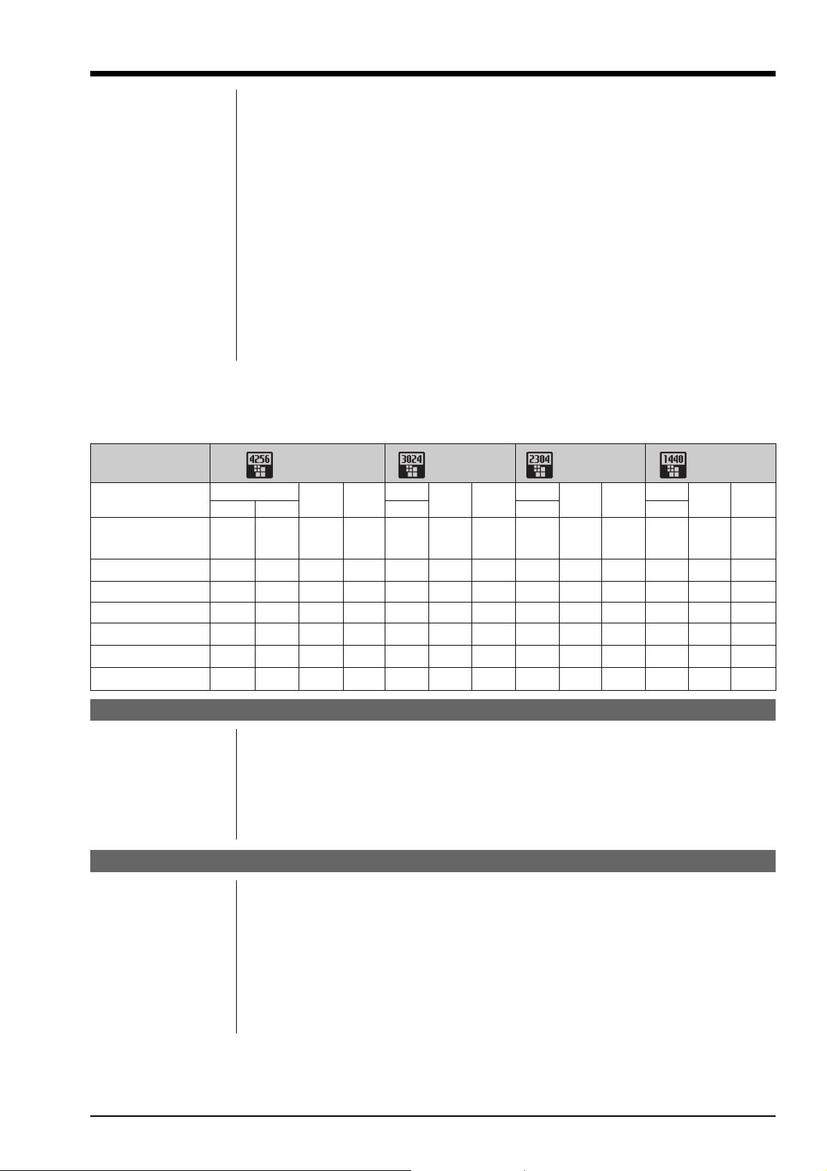
zStandard Number of Available Shots per Media
The number of available shots varies slightly depending on the type of subject. Also, the discrepancy
between the actual number of available shots and the standard number grows as the capacity of the media
increases.
Number of
recorded pixels
Quality Mode
Image File Size
TIFF-RGB
Approx. Approx. Approx. Approx. Approx. Approx. Approx. Approx. Approx. Approx. Approx. Approx. Approx.
35.5MB 12.4MB 4.7MB 2.2MB 17.9MB 2.3MB 1.1MB 10.4MB 1.3MB 660KB 4.1MB 690KB 350KB
4256 × 2848 3024 × 2016 2304 × 1536 1440 × 960
HIGH
CCD-RAW
FINE
NORMAL
HIGH
TIFF-RGB TIFF-RGB TIFF-RGB
FINE
NORMAL
HIGH
FINE
NORMAL
HIGH
FINE
NORMAL
MG-16S (16MB) 0 13606131102332244
MG-32S (32MB) 0 2 6 13 1 12 27 3 22 47 7 45 89
MG-64S (64MB) 1 4 13 28 3 26 55 6 45 94 15 92 180
MG-128S (128MB) 3 9 26 56 7 52 112 12 90 189 30 185 362
Microdrive 340MB 9 26 73 156 19 145 307 33 249 525 84 507 992
Microdrive 1GB 29 80 220 469 58 437 912 100 746 1564 254 1492 2986
Input/Output Sockets
VIDEO OUT For connecting a mini pin jack (3.5 mm dia.) cable for video output to a TV
IEEE1394 socket For connecting a 4-pin IEEE1394 cable for data exchange with a computer and
picture taking from a computer
USB socket For connecting the special USB cable for data exchange with a computer
DC input socket For connecting the special AC Power Adapter AC-5VH/AC-5VHS to supply power
to the camera
Power Source, etc.
Power source CR123A lithium batteries (2)
AA-size batteries (4) (alkaline or nickel-metal hydride)
Special AC Power Adapter AC-5VH/AC-5VHS
Operating conditions Temperature: 0oC to +40oC. (+32oF to +104oF) (Note that the range for Microdrive is
+5oC to +40oC (+41oF to +104oF).)
Humidity: 80% or less (no condensation)
Dimensions (W × H × D)
Mass (Weight) 760 g (26.8 oz.) (body only, not including accessories, batteries or recording media)
141.5 × 131 × 79.5 mm (5.6 × 5.2 × 3.1 in.) (excluding lens and attachments)
5

1.General
zAvailable shots using batteries (When fully charged) *4
FinePix S2 Pro (U/E) SERVICE MANUAL
Battery type
Media type HR-3UF 1700 mAh
SmartMedia Approx. 600 frames Approx. 650 frames
Microdrive Approx. 420 frames Approx. 450 frames
Accessories z Lithium Batteries CR123A (2)
z AA-size Alkaline Batteries (4)
z Strap (1)
z Video Cable (approx. 1.5 m (4.9ft.), mini-plug (3.5 mm-dia.) to pin-plug cable) (1)
z Accessory Shoe Cover (1)
z Camera Body Cap (1)
z LCD Cover (1)
z Eyepiece Cap (1)
z Interface Set (1)
z Owner’s Manual (1)
Optional accessories z SmartMedia
z AC-5VH/AC-5VHS AC Power Adapter
z Fujifilm Rechargeable Battery 2HR-3UF
z Fujifilm Battery Charger with Battery BK-NH (Not Available in U.S.A. / Canada)
z SM-R2 Image Memory Card Reader
z DM-R1 Image Memory Card Reader
z PC-AD3 PC Card Adapter
z Hyper-Utility Software HS-S2 (IEEE1394 Interface)
*1: Images shot in high-sensitivity photography (ISO 400 or higher) may appear coarse and may also be
affected by noise such as white dots.
*2: CCD-RAW is a format specific to the FinePix S2 Pro. The enclosed ‘‘FinePix Viewer’’ software or the
optional Hyper-Utility software ‘‘Shooting Software’’ is required to interpret the images.
*3: Images shot with long exposures (1 second or longer) may appear coarse and may also be affected by
noise such as white dots.
*4: The figures shown for the number of available shots are a guide to the number of consecutive shots that
can be taken at normal temperatures with the flash used in 50% of the shots. Note that the actual
number of available shots may differ due to variations in the ambient temperature when the camera is
used and the amount of battery charge. The number of available shots is lower at low temperatures.
Alkaline batteries
CD-ROM: Software for FinePix EX (1)
Photoshop Element (1)
IEEE1394 4-pin to 6-pin cable (1)
Special USB cable with Noise Suppression core (1)
Software Quick Start Guide (1)
Software Supplementary Guide (1)
MG-4S: 4MB, 3.3V MG-8S: 8MB, 3.3V MG-16S: 16MB, 3.3V
MG-32S: 32MB, 3.3V MG-64S: 64MB, 3.3V
MG-16SW: 16MB, 3.3V, ID MG-32SW: 32MB, 3.3V, ID
MG-64SW: 64MB, 3.3V, ID MG-128SW: 128MB, 3.3V, ID
Compatible with Windows 98/98 SE, Windows Me, Windows 2000 Professional
or iMac or Power Macintosh and models that support USB as standard.
Compatible with Windows 98 SE, Windows 2000 Professional (read-only),
iMac DV and Power Macintosh PCs with FireWire as a standard feature. Mac
OS 8.5.1 to 9.1
Ni-MH batteries
CR123A lithium batteries
Approx. 1000 frames
6

FinePix S2 Pro (U/E) SERVICE MANUAL
1-2. Features
z The newly developed large-size ‘‘Super CCD’’ built into the FinePix S2 Pro provides an ultra-high resolu-
tion, high sensitivity, a large dynamic range and an excellent S/N ratio.
z 6.17 million effective image pixels
z Over 12 million recorded image pixels (4256 × 2848 pixels)
z Supports uncompressed data output for CCD-RAW data
z Wide range of sensitivity settings from ISO 100 to ISO 1600
z Multifunctionality built in to meet the needs of professionals
z 5-point metering AF function
z Shutter speeds from 30 sec to 1/4000 sec.
z Equipped with a synchronizing terminal
z Quick, responsive operation with only 0.5 seconds between shots
z Dual slot for SmartMedia and Microdrives
z Supports 4 types of recorded pixel according to the type of shot
z You can specify independent ISO, color tone, gradation and sharpness settings just as if you were
selecting a film type.
z Histogram function for instant exposure checking after you take a shot
z 1.8-inch low-temperature polysilicon TFT color LCD monitor provides 100% coverage
z IEEE1394 and USB connectivity for quick and easy image file downloading
z DPOF-compatible for simple image printing
z Conforms to ‘‘Design for Camera File system’’ standard and Exif ver.2.2 for digital cameras
* ‘‘Design for Camera File system’’ standard and Exif format are formulated by the Japan Electronics and
Information Technology Industries Association (JEITA)
1.General
Auto Power Off Function: If the camera is not used in any way for a set period, the Auto Power Off function
switches the camera off to prevent battery depletion and to avoid wasting power
when the camera is connected to the AC power adapter. Preview image display
is also cancelled when this function operates.
z The Auto Power Off function does not operate, when a USB connection is
being used, or when the Auto Power Off function is switched off during setup.
CCD-RAW: This is the image data prior to signal processing (the reconstruction of the data
read in from the CCD as an image). Because the signal processing is performed
on the computer, high levels of control are possible.
* To reconstruct images, FinePixViewer (on the enclosed CD-ROM) or the Hyper
Utility (optional) must be installed on your computer.
Color Temperature: Low-temperature light sources, such as a candle flame, are strongly red, while
high-temperature light sources, such as a gas burner flame, are strongly blue.
The color of the light for these temperatures is expressed as a color temperature
(K = Kelvin). The light of the sun at midday in a completely clear sky is taken to
be 5500K.
EV: A number that denotes Exposure Value. The EV is determined by the brightness
of the subject and sensitivity (speed) of the film or CCD. The number is larger for
bright subjects and smaller for dark subjects. As the brightness of the subject
changes, a digital camera maintains the amount of light hitting the CCD at a
constant level by adjusting the aperture and shutter speed.
When the amount of light striking the CCD doubles, the EV increases by 1.
Likewise, when the light is halved, the EV decreases by 1.
JPEG: Joint Photographics Experts Group
A file format used for compressing and saving color images. The compression
ratio can be selected, but the higher the compression ratio, the poorer the quality of the expanded image.
7
1.General
FinePix S2 Pro (U/E) SERVICE MANUAL
TIFF-RGB: A format for saving image data in which a tag indicating the file format is at-
tached to each item of data. Files stored in this format can be opened on a
personal computer.
WAVE: A standard format used on Windows systems for saving audio data. WAVE files
have the ‘‘.WAV’’ file extension and the data can be saved in either compressed
or uncompressed format. This camera use PCM recording.
WAVE files can be played back on a personal computer using the following
software:
Windows: MediaPlayer
Macintosh: QuickTime Player * QuickTime 3.0 or later
White Balance: Whatever the kind of the light, the human eye adapts to it so that a white object
still looks white. On the other hand, devices such as digital cameras see a white
subject as white by first adjusting the color balance to suit the color of the
ambient light around the subject. This adjustment is called matching the white
balance. A function that automatically matches the white balance is called an
Automatic White Balance function.
Exif Print: Exif Print Format is a newly revised digital camera file format that contains a
variety of shooting information for optimal printing.
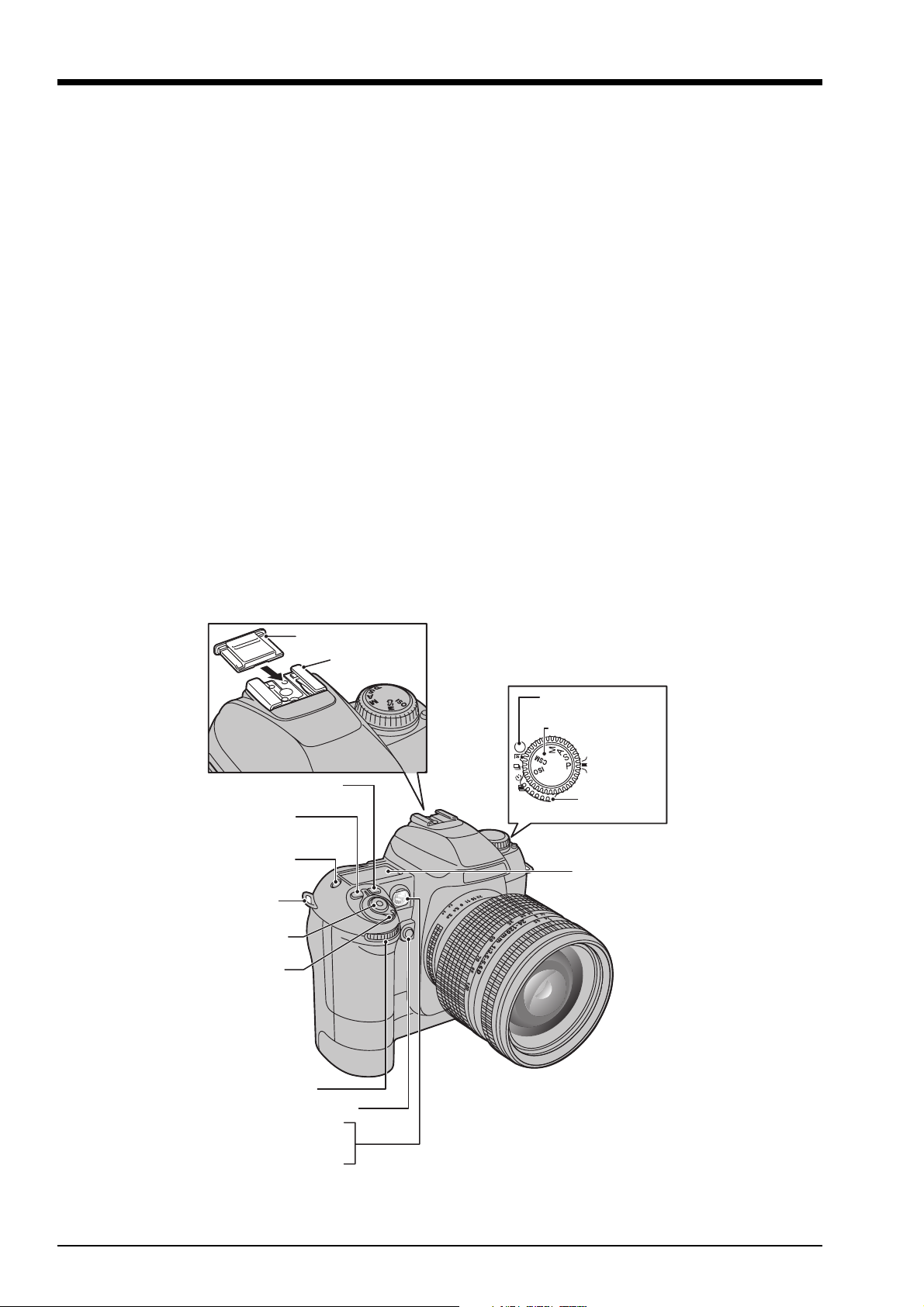
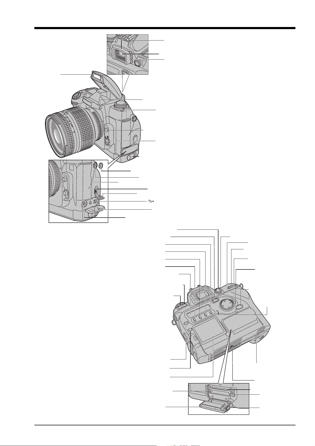
1-3.Names of External Components
Accessory shoe cover
Exposure compensation
button
Flash exposure
compensation button
LCD illuminator
button
Strap mount
Shutter button
Power switch
Accessory shoe
Release mode switch
unlock button
Exposure mode dial
Release mode
switch
Top display panel
Sub-Command dial
Depth of field check button
AF assist illuminator
Self-timer lamp
Red-eye reduction lamp
8
FinePix S2 Pro (U/E) SERVICE MANUAL
r
r
Flash
AA-size battery holder
Synchronizing terminal cap
Synchonizing terminal
VIDEO OUT (visual output) socket
IEEE1394 socket cover
DC IN 5V (Power input) socket
Rubbe
eyecup
Viewfinder
Diopter
adjustment knob
Flash pop-up button
Strap mount
Lens release button
Focus mode
selector switch
release catch
IEEE1394 socket
(USB) socket
Terminal cove
1.General
AE-L/AF-L button
BACK button
F4 button
F3 button
F2 button
F1 button
Rear display panel
Synchro mode button
Auto Exposure
Bracketing button
FUNC button
PLAY button
LCD monitor
Metering system selector dial
4-direction button
Main-Command dial
4-direction button
lock switch
Access lamp
MENU/OK button
Microphone
Battery cover
(Lithium batteries)
Tripod mount
Microdrive slot
Slot cover
SmartMedia slot
Microdrive
eject button
Slot cover
unlock button
9
2. Disassembly
2. Disassembly
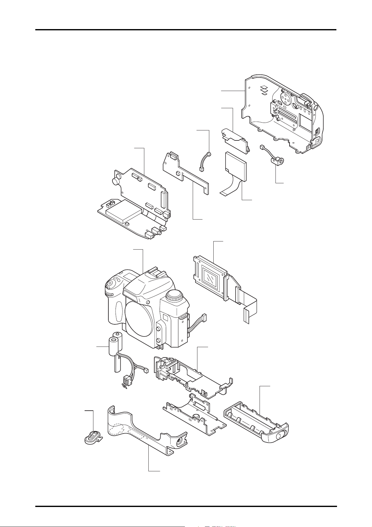
2-1.Names of internal Components
MAIN PWB ASSY
FinePix S2 Pro (U/E) SERVICE MANUAL
R CABI ASSY
REAR LCD PANEL
MIC
SYNCHRO
LCD MONITOR
CAMERA BODY ASSY
CR SPACER ASSY
SW PWB ASSY
CCD HOLDER ASSY
BATT HOLDER
BATT CART
10
BATT LID
FRONT CABI
FinePix S2 Pro (U/E) SERVICE MANUAL
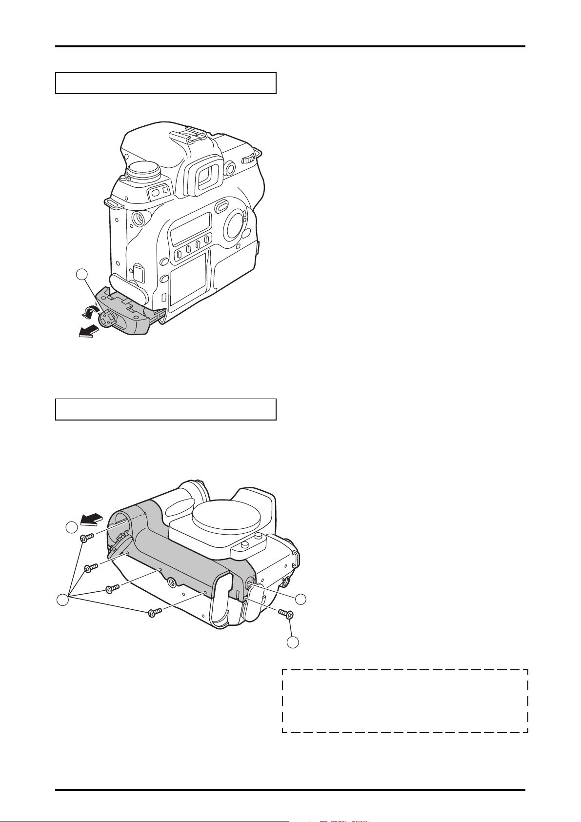
2-2.Removing BATT CART ASSY
Remove in the order indicated by circled numbers.
<Step 1>
1
2. Disassembly
(1)Turn the battery holder lock lever, remove the lock,
and pull out BATT CART ASSY.
2-3.Removing FRONT CABI
Remove in the order indicated by circled numbers.
<Step 1>
2
1
(1) Remove five screws(BB14857-100, M1.7x3.0).
(2) Remove FRONT CABI in the direction of the arrow.
A
1
[ Notes of assembly of FRONT CABI. ]
1.A part must be engaged, and combine FRONT CABI.
2.Confirm there is no space when "FRONT CABI" and "MAIN
BODY" are combined, and the screw is tightened.
11
2. Disassembly
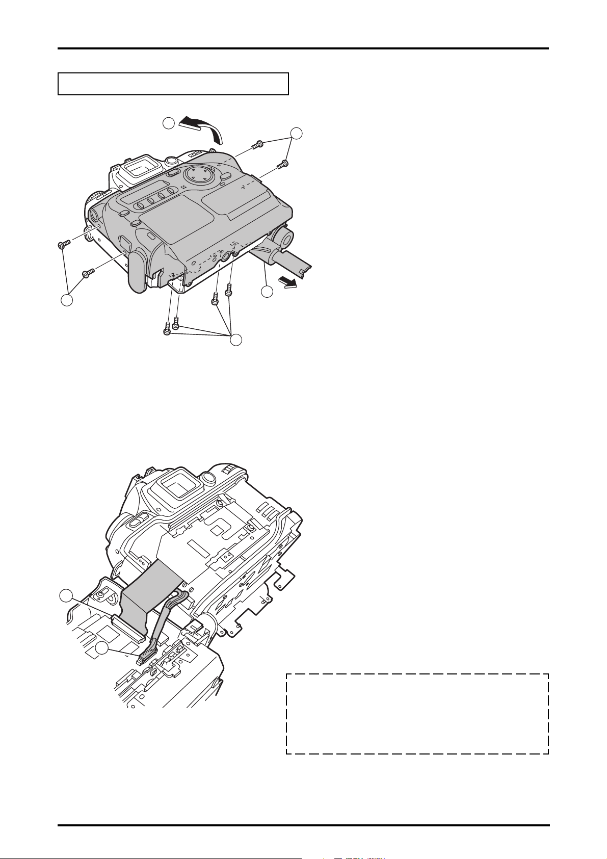
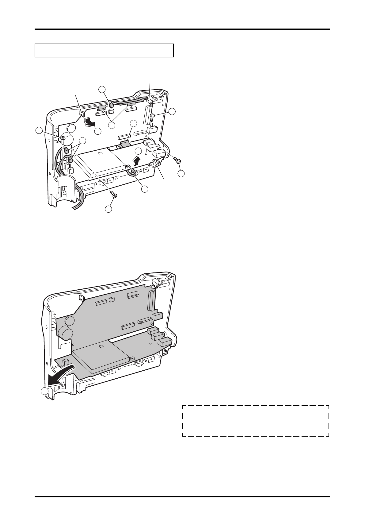
2-4.Removing DSC BLOCK
Remove in the order indicated by circled numbers.
<Step 1>
3
FinePix S2 Pro (U/E) SERVICE MANUAL
2
(1) Pull out CR SPACER ASSY from the camera body in
the direction of the arrow.
(2) Remove eight screws(BB14857-100, M1.7x3.0).
(3) Remove DSC BLOCK in the direction of the arrow.
2
<Step 2>
1
2
(4) Remove the harness from connector (CN300) of
MAIN PWB ASSY.
(5) Remove the lock of connector (CN500) of
MAIN PWB ASSY, and remove FFC.
5
12
4
[Notes of assembly of DSC BlOCK. ]
(1) Note diagonal insertion and the half insertion when you
lock FFC and the harness to the connector.
(2) Confirm there is no space when "DSC BLOCK" and
"MAIN BODY" are combined, and the screw is tightened.
FinePix S2 Pro (U/E) SERVICE MANUAL
2-5.Removing MAIN PWB ASSY
Remove in the order indicated by circled numbers.
2. Disassembly
<Step 1>
1
hook
hook
2
3
5
2
1
3
4
hook
2
(1) Remove four screws(BB12585-100)
(2) Remove the harness from connector (CN700/701/
702/303) of MAIN PWB ASSY.
1
(3) Remove the lock of connector (CN301/302/200) of
MAIN PWB ASSY, and remove FFC.
(4) Remove the hook of BATT HOLDER, and float
MAIN PWB ASSY in the direction of the arrow.
(5) Remove the hook of R CABI ASSY, and float
MAIN PWB ASSY in the direction of the arrow.
1
<Step 2>
6
(6) Remove MAIN PWB ASSY in the direction of the arrow.
[ Notes of assembly of MAIN PWB ASSY. ]
Note diagonal insertion and the half insertion when
you lock FFC and the harness to the connector.
13
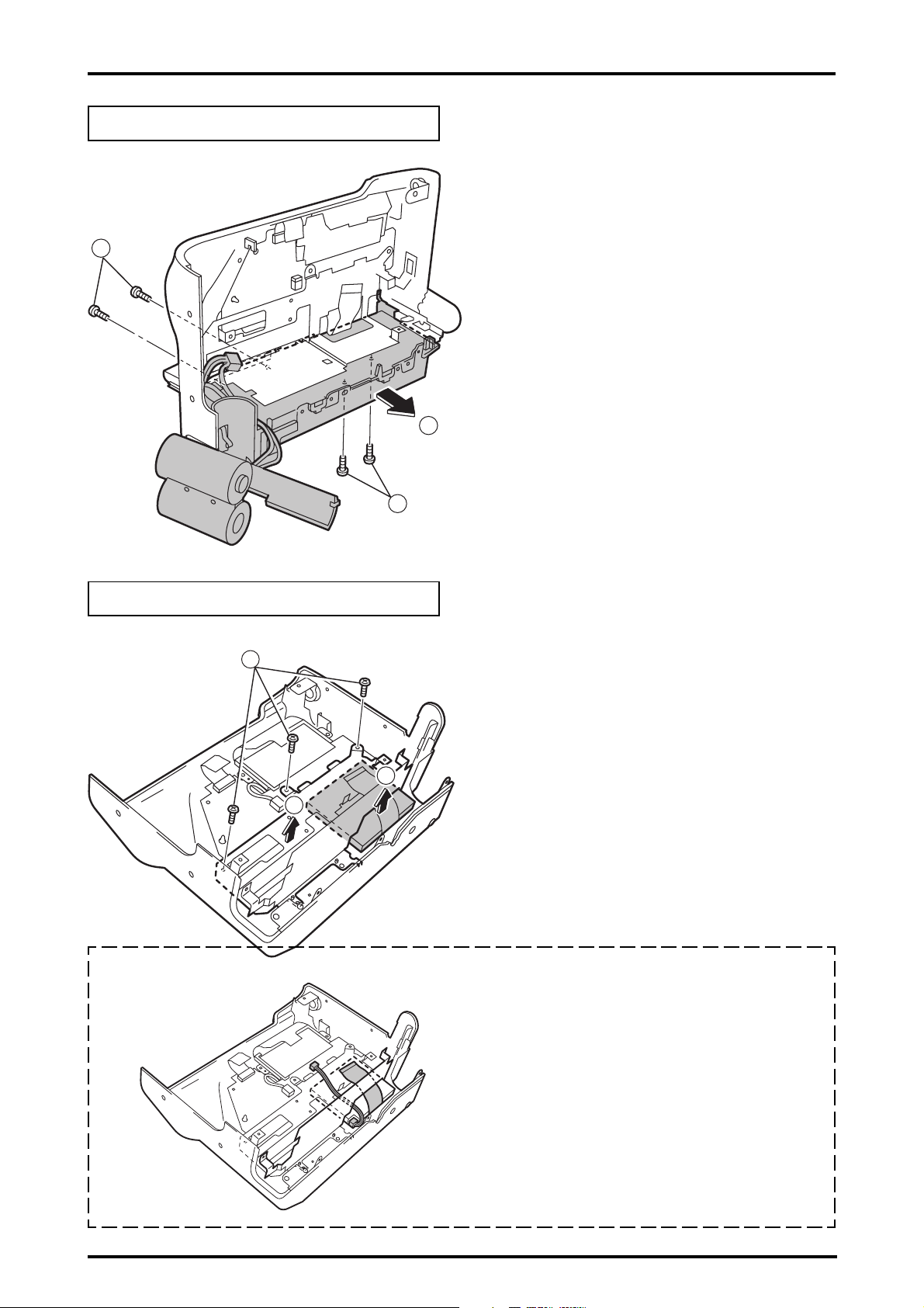
2. Disassembly
2-6.Removing BATT HOLDER ASSY
Remove in the order indicated by circled numbers.
<Step 1>
1
1
FinePix S2 Pro (U/E) SERVICE MANUAL
(1) Remove four screws.
(2) Remove BATT HOLDER ASSY in the direction
of the arrow.
2
2-7.Removing LCD MONITOR
Remove in the order indicated by circled numbers.
<Step 1>
1
2
(1) Remove three screws.
(2) Remove MAIN FRAME ASSY in the direction of the arrow.
(3) Remove LCD MONITOR in the direction of the arrow.
3
[ Notes of assembly of MAIN FRAME ASSY]
Assemble MAIN FRAME ASSY to pinch neither "FPC of
LCD MONITOR" nor "FPC of back light" when you
assemble MAIN FRAME ASSY.
14
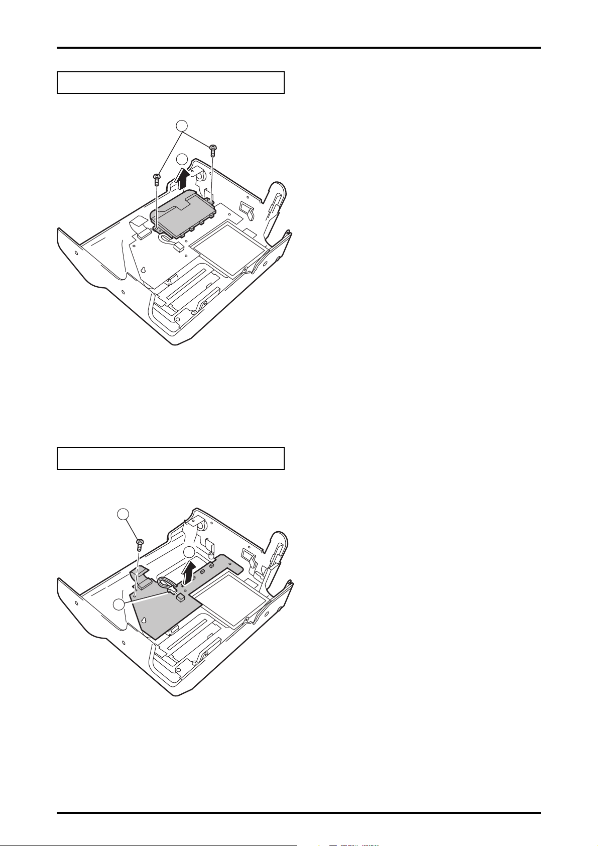
FinePix S2 Pro (U/E) SERVICE MANUAL
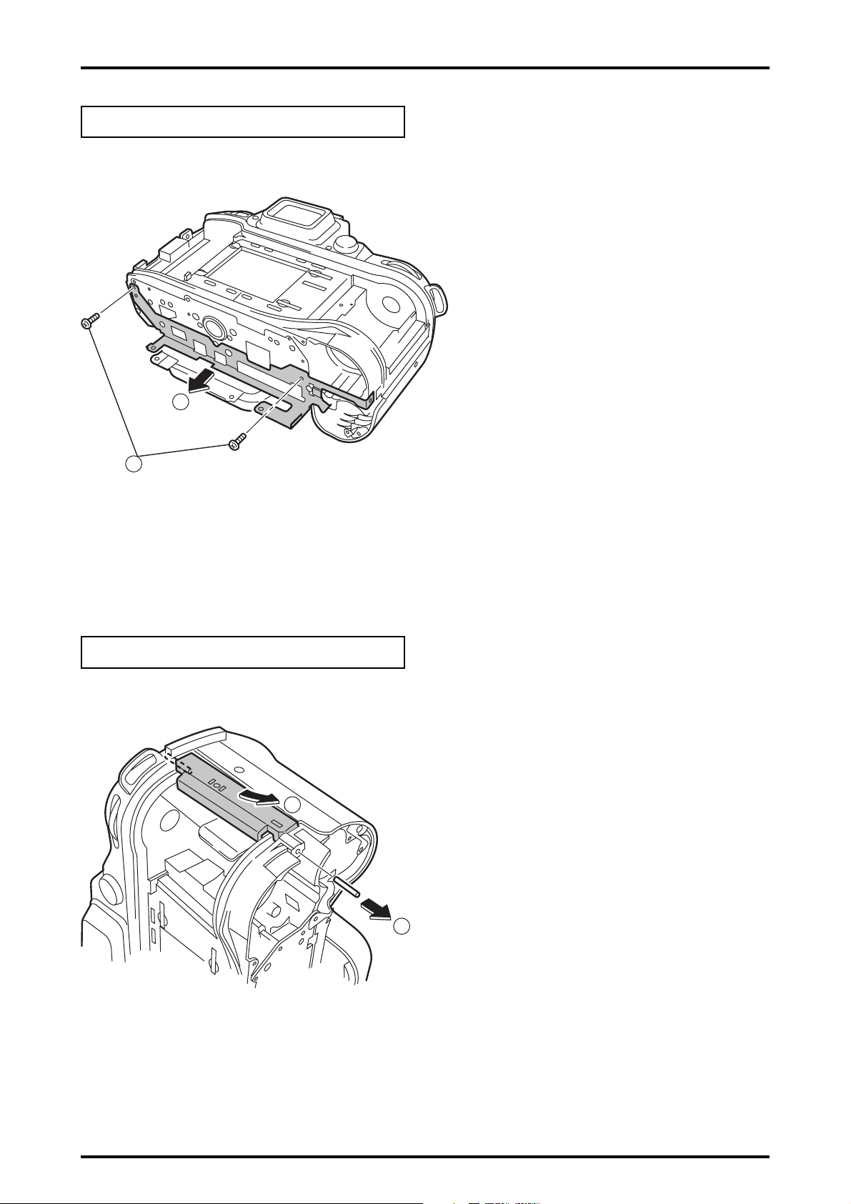
2-8.Removing REAR DISPLAY PANEL
Remove in the order indicated by circled numbers.
<Step 1>
2. Disassembly
1
2
(1) Remove two screws.
(2) Remove REAR DISPLAY PANEL in the direction of
the arrow.
2-9.Removing SW PWB ASSY
Remove in the order indicated by circled numbers.
<Step 1>
1
3
2
(1) Remove one screws.
(2) Remove the harness from connector (CN900) of
SW PWB ASSY.
(3) Remove SW PWB ASSY in the direction of the arrow.
15
2. Disassembly
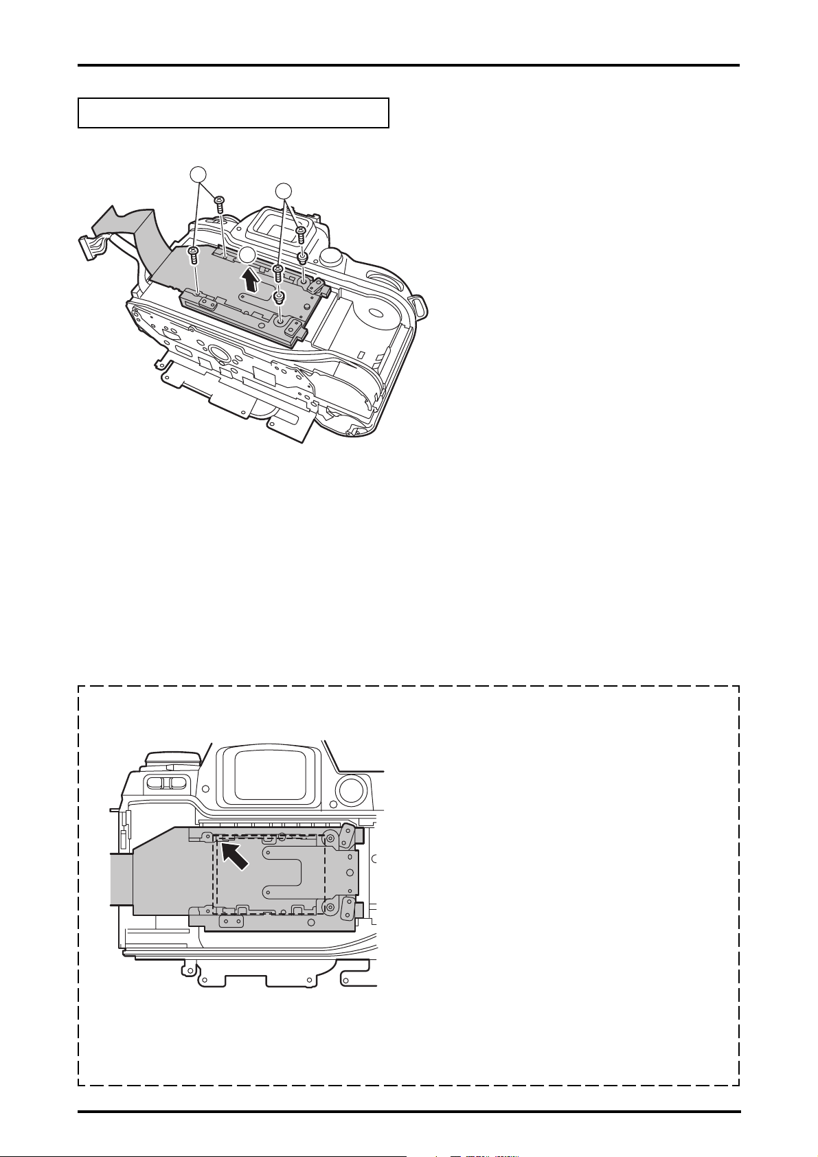
2-10.Removing CCD HOLDER ASSY
Remove in the order indicated by circled numbers.
<Step 1>
1
1
2
FinePix S2 Pro (U/E) SERVICE MANUAL
(1) Remove four screws.
(2) Remove CCD HOLDER ASSY in the direction of the arrow.
[ Notes of assembly of CCD HOLDER ASSY]
Tighten the machine screw according to one side
(direction of the arrow) when you stop four screws.
16
FinePix S2 Pro (U/E) SERVICE MANUAL
2-11.Removing PLATE BOTTOM
Remove in the order indicated by circled numbers.
2. Disassembly
<Step 1>
(1) Remove two screws.
(2) Remove PLATE BOTTOM in the direction of the arrow.
2
1
2-12.Removing GRIP BASE
Remove in the order indicated by circled numbers.
<Step 1>
2
(1) Remove SHAFT.
(2) Remove GRIP BASE in the direction of the arrow.
1
17
2. Disassembly
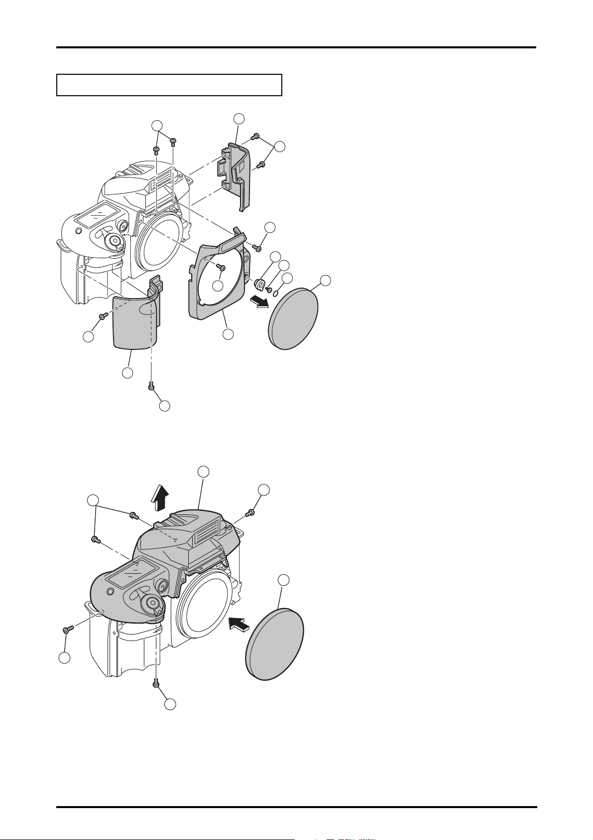
2-13.Removing TOP COVER UNIT
FinePix S2 Pro (U/E) SERVICE MANUAL
Remove in the order indicated by circled numbers.
<Step 1>
6
8
9
11
5
7
(1) Remove the lens cap.
(2) Remove A/M COVER PLATE.
(3) Remove one screw.
(4) Remove A/M CHANGE LEVER.
(5) Remove two screws.
10
(6) Remove two screws.
(7) Remove FRONT COVER UNIT in the direction of the arrow.
(8) Remove two screw.
(9) Remove GLIP COVER in the direction of the arrow.
(10) Remove two screws.
5
4
(11) Remove SIDE COVER in the direction of the arrow.
3
2
1
<Step 2>
13
13
8
(12) Do the lens cap.
14
13
(13) Remove five screws.
(14) Float TOP COVER UNIT in the direction of the arrow.
12
18
13
FinePix S2 Pro (U/E) SERVICE MANUAL
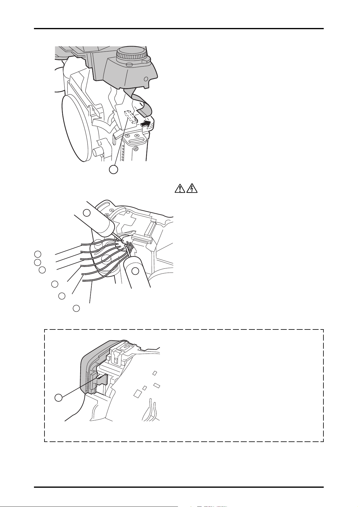
<Step 3>
15
<Step 4>
2. Disassembly
(15) Remove FPC from the TOP COVER side, and
remove TOP COVER UNIT to the grip side.
* As for the grip side, the harness is stopped with solder.
17
17
Blue:
White:
17
Red:
17
Black:
17
Pink:
Light Blue:
17
16
(16) Discharge electricity before removing the harness.
(17) Remove six harness, and remove TOP COVER
UNIT completely.
16
[ Notes of assembly of TOP COVER UNIT ]
Hang part A inner EYE PIECE BARREL UNIT.
And, build in TOP COVER UNIT.
A
19

2. Disassembly
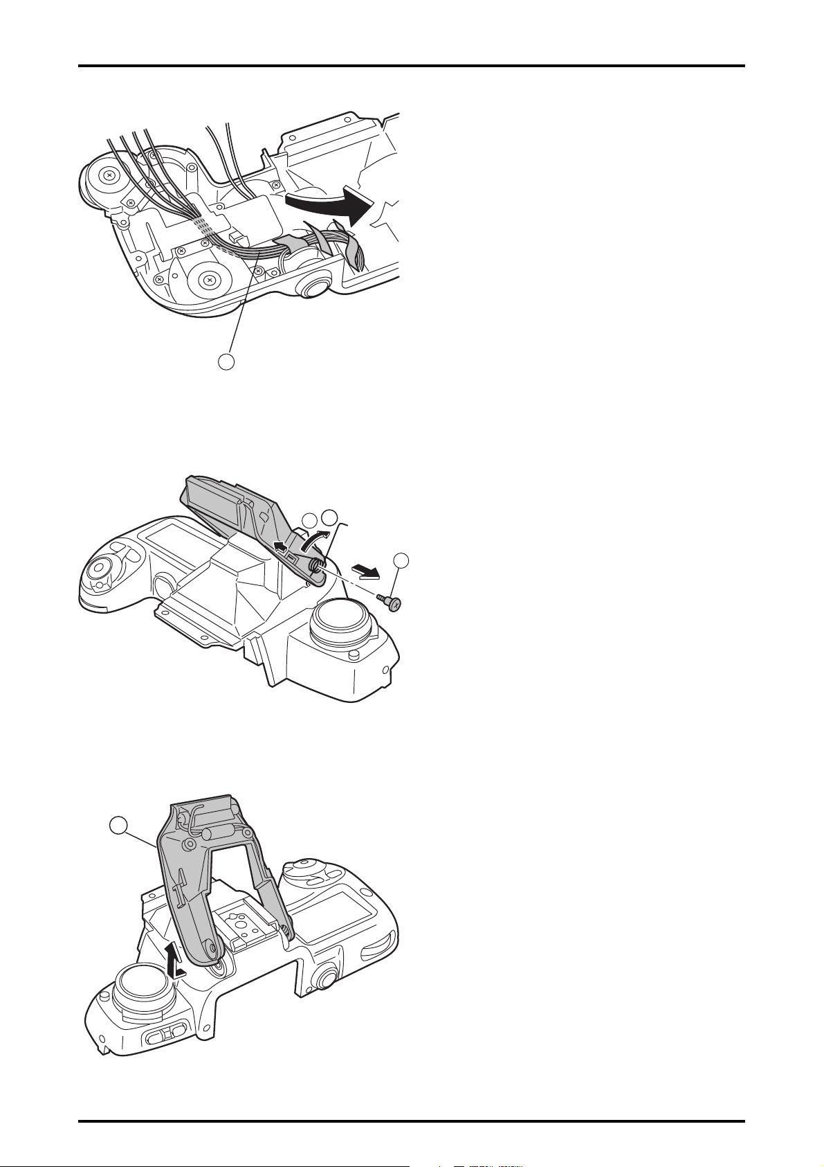
2-14.Removing BODY FPC HARNESS
Remove in the order indicated by circled numbers.
FinePix S2 Pro (U/E) SERVICE MANUAL
<Step 1>
Brown:
Blue:
Black:
Gray:
Purple:
2-15.Removing SB LOWER CASE UNIT
Remove in the order indicated by circled numbers.
<Step 1>
1
(1) Remove soldering from CAMERA BODY, and remove
BODY FPC HARNESS.
Red:
Orange:
Yellow:
Green:
(1) Remove two screws.
(2) Remove the hook in two places.
<Step 2>
2
3
3
3
4
(3) Remove two screws.
(4) Float TOP COVER FPC.
20
FinePix S2 Pro (U/E) SERVICE MANUAL
<Step 3>
5
2. Disassembly
(5) Pull out the harness of the flash in the direction of the
arrow after floating TOP COVER FPC.
<Step 4>
<Step 5>
8
(6) Remove FLASH UP SPRING in the direction of A.
(7) Remove one screws.
A
6
7
(8) Remove SB LOWER CASE UNIT in the direction
of the arrow.
21

3.Schematic
FinePix S2 Pro (U/E) SERVICE MANUAL
3.Schematic
3-1.Cautions
<Caution when replaceing chip (leadless) parts.>
* Do not re-use the removed parts, but use new parts.
Be careful that the negativ side of the tantalum capacitors are susceptible to heat.
* Voltage indications are omitted for capacitors other than chemical and tantalum capacitors
with a dielectric strength of 50 V or less.All units are uF (p shows pF).
* Chip resistors without indication are 1/10 W.
* k=1000
* Variable resistors and semi-variable resistor are abbreviated the specification of B characteristic.
, M=1000 k
3-2.Basic block name and function explanation
Board Name Block name Function
CCD PWB UNIT CCD BLOCK * CCD output(IC100)
MAIN PWB ASSY CAM BLOCK * Analog to digital conversion of CCD output (IC501)
* CCD driver (IC500)
SYSTEM BLOCK *CAMERA BODY management (IC306)
PROCESS BLOCK * Video signal processing (IC306)
* USB communication (IC306)
* System control/SW detection management (IC306)
POWER CONT BLOCK * Power supply management(IC702)
* LCD backlight supply
LCD BLOCK * LCD control (IC201)
IEEE1394 BLOCK *IEEE1394 communication (IC1001)
SW PWB ASSY SW BLOCK * Operation SW
3-3.Description of the Main Block Functions
3-3-1 Overview of the New Technologies
A range of new technologies have been used in this model, and an overview of these is given below.
(1)Improved sensitivity*1 (ISO 1600) and better resolution have been achieved by using a new CCD element that utilizes the
3rd generation Super Honeycom CCD (HA-CCD) structure used in the FinePix S602 but increases the size to APS-film size
(23.3 x 15.6 mm), giving a 6.17 megapixel array with primary color filter.
(This new CCD provides a higher resolution than the FinePix S1 Pro without reducing the S/N ratio, while also allowing
photography at the low ISO 100 sensitivity.)
(2)The optical low-pass filter uses liquid crystal to minimize electrostatic charge, thereby reducing the amount of dust on the
CCD. The surface of the CCD O.LPF has also been given a hard coating to make cleaning easier and more effective.
(3)Image data compression and expansion is performed by the hardware (UCS1; IC306)*2, allowing shorter intervals
between shots at an image size of 4256 pixels x 2848 lines. (The same hardware as the FinePix-S602 is used.)
(4)The camera body used is based on the Nikon F80 camera and takes Nikon's interchangeable lenses.
(5)In response to strong demand from business users, a high-speed IEEE 1394 interface has been provided, along with the
addition of a CCD-RAW format recording function.
*1The Honeycom signal processing roughly doubles the valid number of image pixels, concentrating the data for 4 pixels
into one. This process quadruples the signal level (sensitivity), doubles the S/N (signal-to-noise) ratio and allows shots to
be taken at sensitivity settings up to ISO 1600.
*2The hardware (UCS1; IC306) consists of an M32R core, SRAM and a single chip that provides both the standard peripheral
I/O functions and the functions required by the DSC system. The standard peripheral I/O modules (CPU peripheral I/O
module) comprise an interrupt controller (ICU), system controller (SYSC), DMA controller (DMAC), clock controller (CLKC),
SDRAM controller (SDRAMC), block select controller (BSELC), serial I/O (SIO) interface, USB (USB) interface, multi-function
timer (MFT), watchdog timer (WDT), programmable I/O port (PIO), AD converter (ADC) and DA converter (DAC). In addition,
a JPEG controller (JPEG), signal processor (YCPRO), internal buffer controller (IBFC), AUTO processor (IBFC), media
controller (MEDIA), encoder (ENCD), character generator (CGEN), LCD controller (TFDC), IEEE 1394 interface (EXIO) and
MPEG-2 interface (EXIO) are included as the function modules required for the DSC system (image I/O modules).
22

FinePix S2 Pro (U/E) SERVICE MANUAL
3.Schematic
3-3-2 Block function descriptions
(1) Imaging circuit (CCD BLOCK) (CAM BLOCK)
The analog video signals output from the new APS-size Honeycom CCD (APS-size 6.17-megaixel CCD) are processed
using false-color correction (CDS), optimized spacing (CDS), amplification (AGC) and signal mixing (CDS) in a single CSPIC chip (IC501; abbreviated as SCS3A), before being converted (A-D) to 12-bit digital signals. The CSP-IC also incorporates
the "TG/SSG" function, previously provided as a separate IC, onto one chip. The converted digital signals are then sent to the
signal processing IC (abbreviated as UCS1; IC306; CSP).
(2) Image processor (PROCESS BLOCK)
(Input data from the CCD)
The 12-bit digital image data (the section corresponding to 1H) generated by the imaging unit (CCD-CAM BLOCK) is sent to
the signal processing IC (abbreviated as UCS1; IC306), where buffer processing is performed in the IC's internal buffer to
convert the signals to 32-bit (16-bit x 2) data (CCD-RAW data). The converted 32-bit data (CCD-RAW data) is stored in the
16MB SDRAM (IC307 to IC310) via the I/O bus for the image signal processing IC. The image data for each frame (4256
pixels x 2848 lines) is temporarily stored in SDRAM. Also, the 32-bit image data input to the signal processing IC (abbreviated
as UCS1; IC306) is used for additions performed by the AUTO computing unit and then sent to the CAM BLOCK SCS3A
(IC501) so that the optimal AE, AWB and AF values are obtained.
(Recording onto the SSFDC/Microdrive)
The image data stored in the SDRAM (IC307 to IC310) is sent one line at a time to the signal processor IC (IC306; UCS1;
CSP) via the I/O bus in the signal processor IC. In the signal processor, the data is unpacked and the following processes
are called: 16 bit -> 10 bit conversion; preprocessing such as digital clamping, gamma correction, and 10-bit -> 8-bit
conversion for the R, G and B channels; YC processing to convert the 8-bit RGB signals to Y:Cb:Cr=4:2:2, after which the Y,
Cr and Cb 8-bit image data is returned to the internal buffer. In the internal buffer, the 8-bit Y, Cr and Cb signals are sorted
into a data format that facilitates DCT compression before being recorded onto an SSFDC or Microdrive via the JPEG
calculation unit and media controller.
(Image playback from the SSFDC or Microdrive)
The compressed image data on the SSFDC is sent to the signal processing IC (abbreviated as UCS1; IC306) as 8-bit
image data and then sent to SDRAM (IC307 to IC310) via the media control unit, the DMA unit and the internal buffer control
unit. The image data temporarily stored in SDRAM (IC307 to IC310) is then returned to the signal processor IC (abbreviated
as UCS1; IC306) and sent to the signal processor unit via the media controller and JPEG calculation unit. The signal
processor unit performs postprocessing in which the 8-bit Y:Cr:Cb image signals are converted to 8-bit R, G and B signals.
At the same time, the character display signals are superimposed and sent to the LCD BLOCK.
The imaging system adjustment data is stored in F_ROM (IC314).
The 8-bit brightness and color-difference signals processed by the signal processing IC (UCS1; IC306) are D-A converted
in the image signal processing IC encoder unit and the display character signals are superimposed, producing analog
RGB signals. Video (a composite video signal) is also included at the same time in the B component of the RGB signal
output. When the VIDEO terminal is inserted into the camera, a composite video signal is automatically output by the detector.
(3) LCD Controller (LCD BLOCK)
The RGB analog signals output from the image signal processing IC encoder block are sent to the LCD controller IC
(IC201), where they are converted to digital RGB signals. The LCD controller IC also controls the LCD panel gradations at
the same time.
3-3-3.Description of the Power Supply Block Functions
The power supply circuit mounted on the MAIN PWB ASSY board generates a 3.3-volt (IEEE-IC IC1001, UCS1 IC306, SCS3A
IC501, CARD IC201, +16V/-9.0V (CCD power supply)), 7.5-volt (LCD backlight power supply) or 12-volt (LCD panel) supply.
3-3-4.Description of the camera body block functions
The main CPU governs AE calculation and control, AF calculation and control, shutter control, and all communication,
including communication with the DSC unit.
Generation of the power supply and the viewfinder LCD are directly controlled by the SUB CPU.
The interface IC on the MAIN PCB operates as an interface with the AF signals from the linear line sensor (in the CCD FPC)
and sends the AF data to the MPU. It then receives control signals from the MPU and uses these to drive the AF motor.
This IC also controls built-in flash charging and the viewfinder LED.
The camera adjustment parameters are stored in the EEPROM on the MAIN PCB.
The light-metering IC in the pentaprism FPC sends 6-zone light-metering data chronologically to the MPU on the MAIN PCB.
The AF motor drives AF lenses.
The CCD in the CD FPC is a linear line sensor that performs image detection for AF.
23
FinePix S2 Pro (U/E) SERVICE MANUAL
3.Schematic
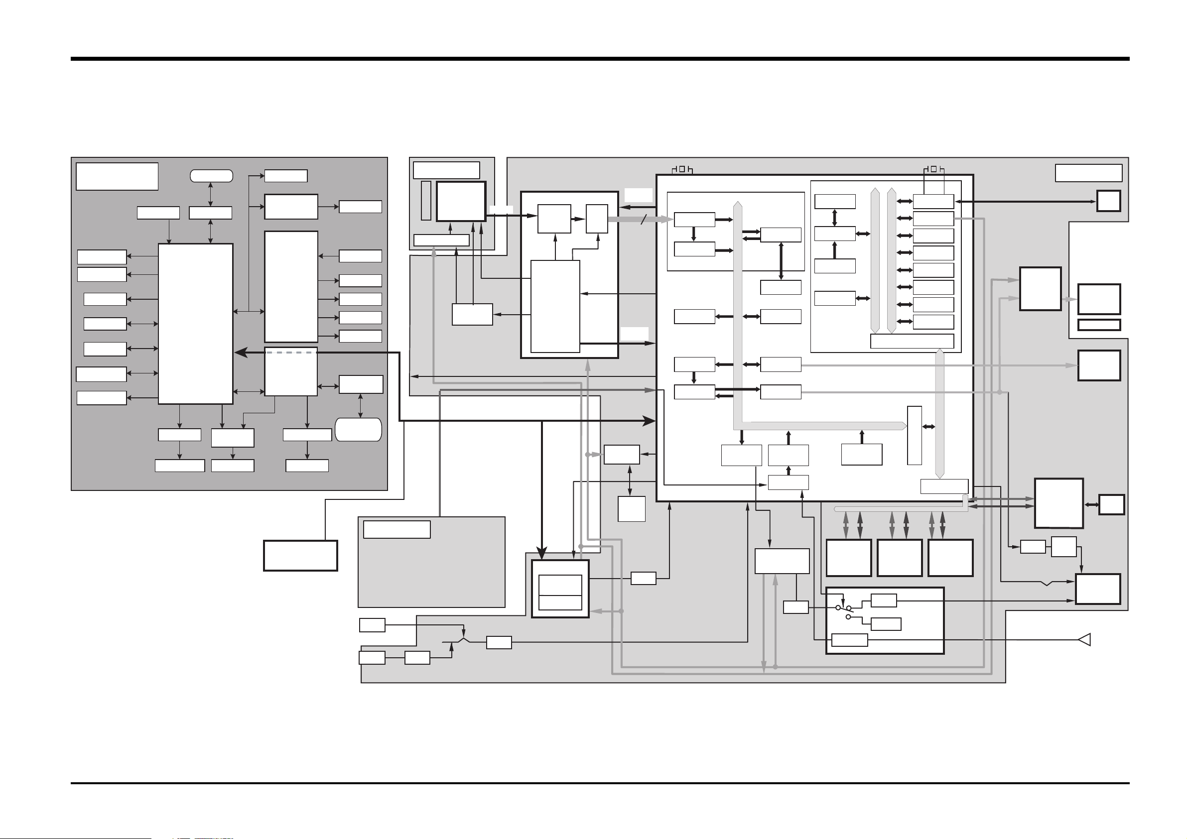
3-4. Block Diagram
CAMERA BODY
LEADING CURTAIN
TRAILING CURTAIN
IRIS MAGNET
AF CCD
AE SENSOR
METERING SENSOR
AF ASSIST
ILLUMINATOR
LENS
VAR IOU S
SWITCHES
LENS CONTACT
MAIN CPU
MOTOR DRIVER
SEQUENCE MOTOR FLASH UNIT
FLASH CONTROL
EEPROM
LCD DRIVER
SUB CPU
INTERFACE IC
MOTOR DRIVER
AF MOTOR
LCD IN FINDER
VARIOUS
SWITCHES
SI LCD
ILLUMINATION
LCD
EXTERNAL LCD
DC/DC
CONVERTER
ACCESSORIES
SHOE
SYNCHRONIZING
TERMINAL
CCD PWB UNIT
Super-CCD
O.LPF
23.0mm x 15.5mm
6.17million Pixels
IC100
OFD/RG IC101
SCS3A IC501 (CSP)
CCD_IN
V-DRV
IC500
RxD,TxD,DSC_DET,DCS,
DSC_On,Release,Shutter,Synchro,GND
DSC_ON
ANALOG
BLOCK
VARIOUS
PULSE
TG
(PROGRAMABLE)
ADCLK
A/D
(12bit)
CCD CLK
24.5MHz
AVD,AHD,
ADCK,FI
DETECTION
DATA/TIME
IC302
BATT
Back-up
12
X'TAL
24.5MHz
UCS1 IC306 (CSP)
IBUF
CCD I/F
AUTO
TFDC
BITMAP CG
ENCD
YC I/F
IMAGE BUS 32bit/75MHz
YC PRO
JPEG
MADIA
D/A (4ch)
AUDIO
(SERIAL)
AUDIO
(A/D)
A/D
MICON CORE
SDI
CPU CORE
I-cache 8KB
SDRAM 32KB
MICON I/O BUS 32bit/75MHz
IEEE1394
(A/D)
USB
SIO
CPU BUS 32bit/75MHz
BUS CONTROL
WDT
MFT
ICU
ADC
PORT
CLKC
IMAGE BUS I/F
I/O BUFFER
X'TAL
48MHz
BRIDGE BUS 32bit/75MHz
R/G/B
VBS
D+,D-,VBUS
LCD-CONT
IC201
IEEE1394-
IC1001
(16Mb)
MAIN PWB ASSY
USB
OUT
LCD
Monitor
LED_BL
SSFDC
CF(MD)
SOCKET
DRV
1394
OUT
SYNCHRONIZED
TERMINAL
KEY PWB UNIT
BATT
AA LR6
DC IN
DC Jack
FUSE
[KEY]
MENU/EXE
CANCEL
FUNC
PLAY
BACK
4-DIRECTION
VDET
DC/DC BLOCK
CONTROL IC
IC702
EVR (4ch)
RESET
VDET
EVR D/A
EVR D/A
8ch
IC502
SO1,SI1,SCL1
8ch
IC502
LPF
SDRAM
IC307,308
(256Mb)
(x16)
Vol
MIC_AMP
SDRAM
IC309,310
(256Mb)
(x16)
AMP
SP_AMP
AUDIO BLOCK IC600
FLASH ROM
IC314
(16Mb)
(EEPROM)
AV_DET
LPF
75 ohm
Drv.
VIDEO
OUT
MIC
24
FinePix S2 Pro (U/E) SERVICE MANUAL
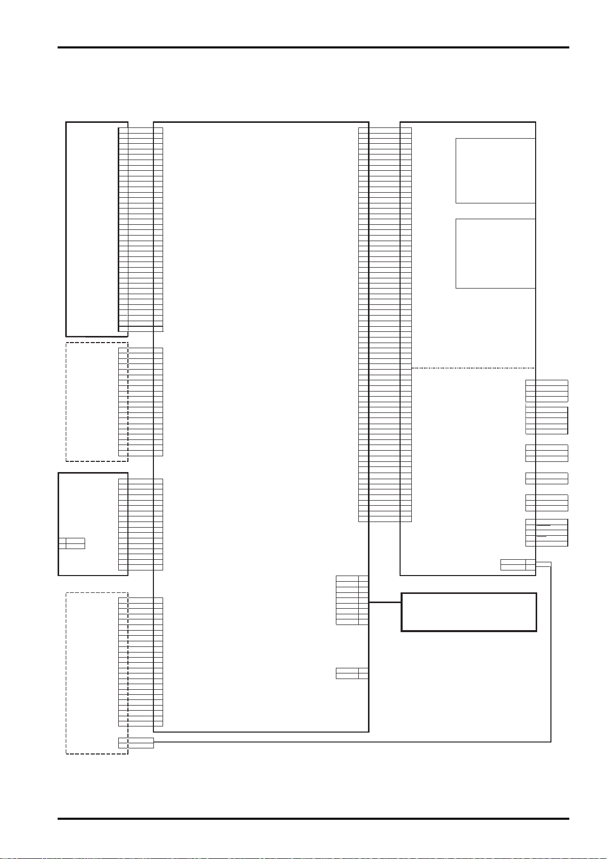
3-5. Overall Connections
3.Schematic
1
22 D33 D+
4
5
6
77 CCD_ON
88
99 BL_ON
1
010 MIC_ON
11
12
13
14
CCD PWB
ASSY
REAR display
SW PWB ASSY
MIC
1
MIC+ 3.3V
CN900
2 MIC- GND
LCD monitor
15
16
17
18
19
20 20
CN101
21 21
22 22
23 23 VBS
24
25 25
26 26
27 27
28 28
29 29
30 30
31 31
32 32
33 33
34 34
35
36
37
38
NC 20 CCD_ 6V
CS
RES 18 GND
A0
SCL
SI 15 MIOW
VDD 14 MIOR GND
VOUT
CAP3- MWE 4NC
CAP+
CAP- 9 MPA0
CAP2+ 8 MPA 2DCAP2- 7 MPA2 3D+
V
V2 5 MPA4 5
V3
V4 3 MPA6
V5 2 MPA7
VR
1
2 CANCEL 2
3 EXE 3 MD2
4DISP 4 MD UNREG
5 FUNC 5
6 KEY_L 6 3 UNREG_GND
7 KEY_CL 7 MWAIT
8 KEY_CR 8 MRDY
CN901
9 KEY_R 9
1
0 BLR_ON 0
11
12
13
14
15
16
17
TESTL
COM 23 RXD 6
VST 22 TXD 7
VCK 21 SYNC 8
EN 20 GND 9
DWN
VDD
VDDG
VSSG
TEST2 14
WIDE
HST
REF HOT
TEST 10 GND 2
C/REXT 9
HCK2
HCK 7
PSIG
GREEN 5
RED 4
BLUE 3
RGT 2
TESTR
1
2
1
ATT1/3
ATT2/3
ATT3/3
SUB0
V8
V7
V6
V5
V4
-9V
V38
V3A
V2
V1B
V1A
RS
+11V
GND
GND
CCD_OUT
GND
GND
OFFSET_D
RS_DET
OFD_DET
O.S._EVR
RS_EVR
OFD_EVR
OD2_CNT
16V
16V
GND
GND
H1
H2
5.4V
5.4V
5.4V
VSS
KEY_
MIC_VCC
MIC+
MICCARD_LED HOT
GND COLD 2
4 GND
5 VBUS
6 GND
11
12 CF_ON
13
14
15
16
17
18
19
CN500
24
35 D_3.3V
36
37
38
19
17
16
13
12
11
CN302
10
6 MPA3
4 MPA5
1
1
CN301
1
11
12
13
14
15
16
17
24 Shutter 5
MAIN PWB ASSY
CN300
CS
DSC_DET 2
DSC_ON 3
Release 4
GND
LCD 2V_ON
DR_SW
CAM_ON
PW_ON
CAM_BATT
DCEEP_CS
CARD_DET
CARD_DET
CF_CE
CF_DET
MIOIS
GND
GND
CPU_UNREG
DA_3.3V
GND
5.7V
5.4V
.8V
GND
A3.3V
GND
3.3V
5V
GND
LCD_ 2V
GND
CCD_-8V
GND
8V
MREG
MCE 2 VBS
MOE 3NC
MRST
MPA8 2 GND
MPA9 3 UNREG_GND
MD7
MD6
MD5 UNREG
MD4 2 UNREG_GND
MD3
MD0 2 CAM_BATT
MAIN PWB ASSY
SmartMedia
CN800
Microdrive
CN801
J701
CN304
J700
CN700
CN701
CN1001
CN702
CAMERA BODY
19
18
17
VSS
16
15
13
CN200
HOT
GND
12
11
8
6
1
CN303
Synchro terminal
VIDEO_OUT
1
1
VBUS
4
GND
F_GND
1
UNREG
1
CR SPACER
1
1
TPA
2TPA
3TPB
4
TPB
5
GND
1
USB
DC_IN
AA LR6
IEEE1394
25
3.Schematic
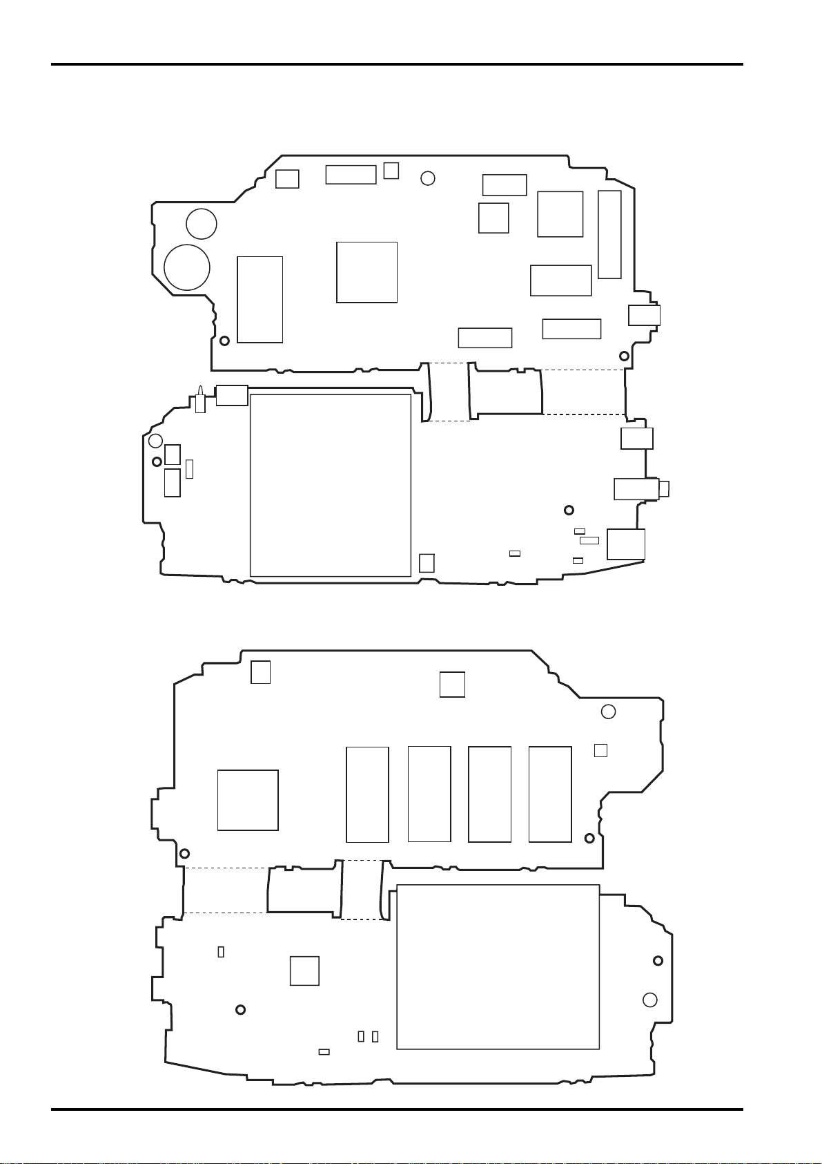
3-6.Board mounting diagram
3-6-1.Printed wiring board of MAIN PWB ASSY.
< A side >
FinePix S2 Pro (U/E) SERVICE MANUAL
CN800
CN301
CN303
IC306
IC302
BT300
BZ300
IC314
CN800
CN700
A
F701
CN701
A
CN702
IC201
CN200
CN302
F707
IC501
IC500
CN300
F703
F704
F700
CN500
CN1001
CN304
J701
J700
< B side >
F705
IC1001
IC502
IC702
IC310
IC600
B
IC319
IC307IC308IC309
CN810
B
26
F708
F702
F706
FinePix S2 Pro (U/E) SERVICE MANUAL
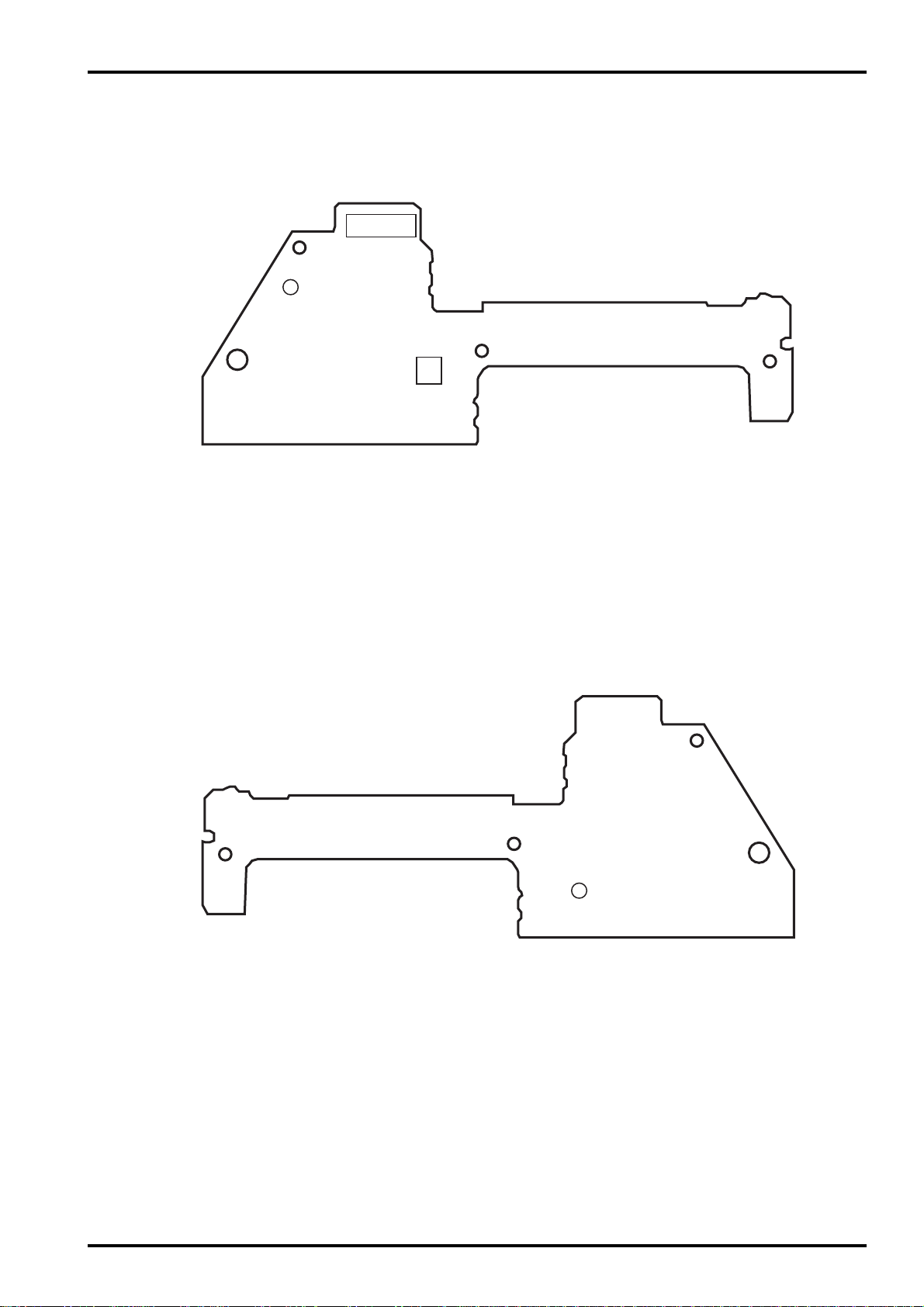
3-6-2.Printed wiring board of SW PWB ASSY.
< A side >
CN901
A
3.Schematic
CN900
< B side >
B
27
 Loading...