

Page 1
Instruction Manual
NON-DISPERSION TYPE
INFRARED GAS ANALYZER
TYPE: ZRF
IN
FR
AR
ED
G
AS
AN
ALY
ZER
NO
PO
W
ER
O
N
O
FF
SO
O
MEAS
FUNC
2
2
COMP
MEAS
>
SPAN
∧
ENT
vol%
ppm
vol%
ppm
vol%
ppm
HOLD
ZERO
R
M
T
R
A
N
SPAN
RANG
E
RANG
E
RANG
E
G
E
AUTO CAL
CAL
Fuji Electric Co.,Ltd. INZ-TN1ZRFb-E
Page 2

PREFACE
Congratulations on your purchase of Fuji’s Infrared Gas Analyzer (Type: ZRF).
• Before using, be sure to read this instruction manual carefully to ensure correct installation,
operation and maintenance of the infrared gas analyzer. Note that incorrect handling may lead
to trouble or personal injury.
• The specifications of this infrared gas analyzer are subject to change for improvement without
prior notice.
• Do not attempt to modify the infrared gas analyzer without permission. Fuji is not responsible
for any trouble caused by modification without permission.
• This instruction manual should always be kept on hand by the user.
After reading, be sure to keep this manual in a place where it can easily be seen by the operator.
•
• Make sure that this manual is presented to the final user.
Manufacturer : Fuji Electric Co., Ltd.
Type : Described in Fuji Electric’s company nameplate on main frame
Date of manufacture : Described in Fuji Electric’s company nameplate on main frame
Product nationality : Japan
Delivered items
Analyzer main frame .................................................... 1
Fuse (2A) ......................................................................2
Cell assembling tool (only for block cell) .................... 1
Instruction manual ........................................................1
Test report ..................................................................... 1
Mounting fixture (in case of panel flush mount) .......... 4
NOTICE
• It is prohibited to transfer part or all of this manual without Fuji
Electric’s permission in written format.
• Description in this manual will be changed without prior notice
for further improvement.
i
© Fuji Electric Co., Ltd., 1990
Issued in Sept., 1990
Rev. 1st ed. in July, 1993
Rev. 2nd ed. in Apr., 1997
Page 3
SAFETY PRECAUTION
First of all, read this “Safety Precaution” carefully, and then use the analyzer in the correct way.
• The cautionary descriptions listed here contain important information about safety, so they should
always be observed. Those safety precautions are ranked 2 levels; “DANGER” and “CAUTION”.
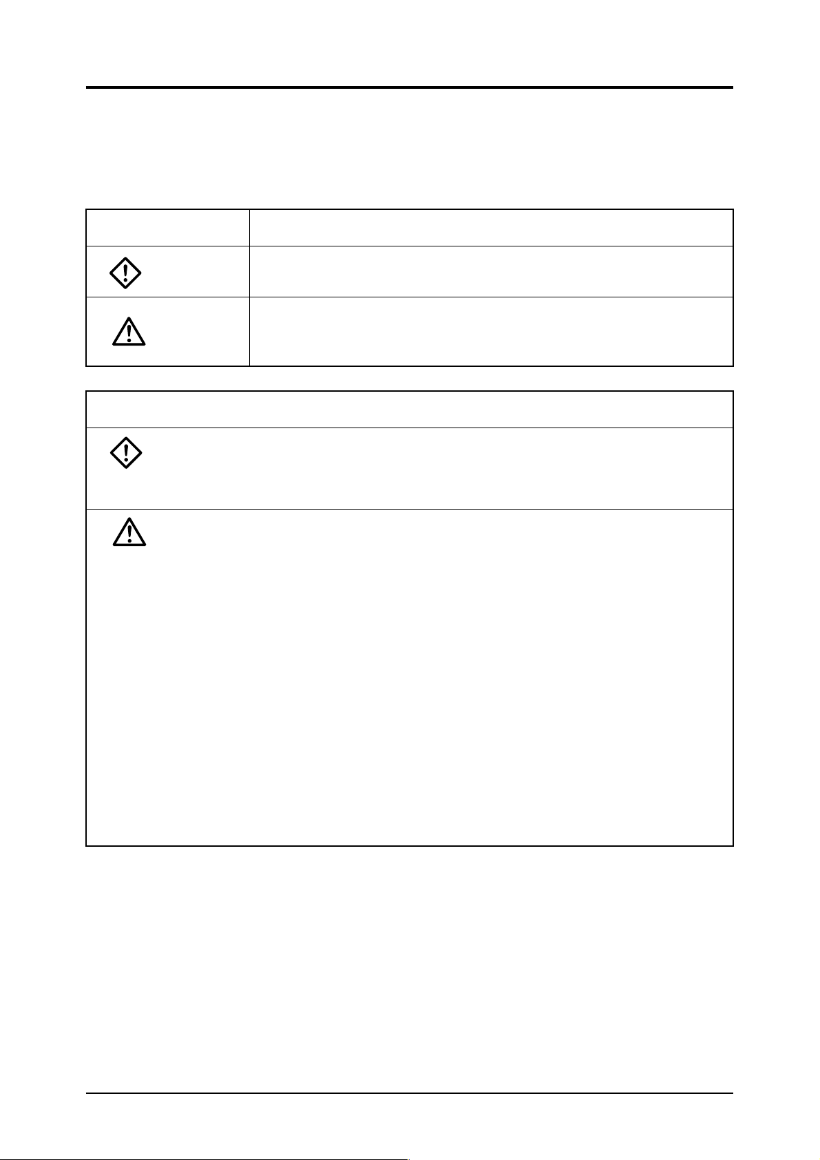
Warning & Symbol
DANGER:
CAUTION:
Caution on installation and transport of gas analyzer
DANGER: This unit is not an explosion-proof type. Do not use it in a place
CAUTION: • For installation, observe the rule on it given in the instruction
Meaning
Wrong handling may cause a dangerous situation, in which there
is a risk of death or heavy injury.
Wrong handling may invite a dangerous situation, in which there is
a possibility of medium-level trouble or slight injury or only physical
damage is predictable. .
with explosive gases to prevent explosion, fire or other serious
accidents.
manual and select a place where the weight of gas analyzer can
be endured.
Installation at an unsuited place may cause turnover or fall and
there is a risk of injury.
• For lifting the gas analyzer, be sure to wear protective gloves.
Bare hands may invite an injury. .
• Before transport, fix the casing so that it will not open. Otherwise, the casing may be separated and fall to cause an injury.
• The gas analyzer is heavy. It should be transported carefully.
Otherwise, body may be damaged or injured.
• During installation work, care should be taken to keep the unit
free from entry of cable chips or other foreign objects. Otherwise, it may cause fire, trouble or malfunction of the unit.
ii
Page 4
Caution on piping
DANGER: In piping, the following precautions should be observed. Wrong
piping may cause gas leakage.
If the leaking gas contains a toxic component, there is a risk of
serious accident being induced.
Also, if combustible gas is contained, there is a danger of explosion, fire or the like occurring.
• Connect pipes correctly referring to the instruction manual.
• Exhaust should be led outdoors so that it will not remain in the
locker and installation room.
• Exhaust from the analyzer should be relieved in the atmospheric
air in order that an unnecessary pressure will not be applied to
the analyzer. Otherwise, any pipe in the analyzer may be disconnected to cause gas leakage.
• For piping, use a pipe and a pressure reducing valve to which oil
and grease are not adhering. If such a material is adhering, a
fire or the like accident may be caused.
Caution on wiring
CAUTION: • Wiring is allowed only when all power supplies are turned off.
This is required for preventing a shock hazard.
• Enforce construction of specified grounding wire by all means. If
the specified grounding construction is neglected, a shock hazard or fault may be caused.
• Wires should be the proper one meeting the ratings of this instrument. If using a wire which cannot endure the ratings, a fire may
occur.
• Use power source that matches the rating of the unit. Use of
power source out of rating may cause fire.
Caution on use
DANGER: • When handling the standard gas such as calibration gas, read
the instruction manual of the standard gas carefully and use the
gas correctly.
CAUTION: • Avoid continuous operation with the casing drawn out.
• During operation, avoid opening the casing and touching the
internal parts. Otherwise, you may suffer a burn or shock hazard.
iii
Page 5
Caution on maintenance and check
DANGER: • When doors are open during maintenance or inspection for
adjusting the optical system, etc., be sure to purge sufficiently
the inside of the gas analyzer as well as the measuring gas line
with nitrogen or air, in order to prevent poisoning, fire or explosion due to gas leaks.
CAUTION: • Before working, take off a wrist watch, finger ring or the like
metallic accessories. And never touch the instrument with a wet
hand, Otherwise, you will have a shock hazard.
• If the fuse is blown, eliminate the cause, and then replace it with
the one of the same capacity and type as before. Otherwise,
shock hazard or fault may be caused.
Others
CAUTION: • If the cause of any fault cannot be determined despite reference
to the instruction manual, be sure to contact your dealer or Fuji
Electric’s technician in charge of adjustment. If the instrument is
disassembled carelessly, you may have a shock hazard or injury.
• Do not use a replacement part other than specified by the instrument maker. Otherwise, adequate performance will not be
provided. Besides, an accident or fault may be caused.
• Replacement parts such as a maintenance part should be disposed of as incombustibles.
iv
Page 6

CAUTIONS ON USE
Select a suitable installation place.
Install the unit in a place with normal temperature and humidity, free from excessive change in
temperature and from heat radiation and direct sunlight.
This unit is designed for indoor installation. When it is installed outdoors, choose a place where it
is not exposed to wind and rain. Be sure to use a proper case cover.
Do not install the unit in a place with vibrations.
Cleaning of instrument
Do not use solvents such as benzine, thinner, etc., as it damages the case.
Use the unit in a place with good environment.
The unit should be used in a place free from corrosive or combustible gases.
Be careful with electric shocks.
The unit should be earthed to avoid electric shocks.
Key operation
Do not use any object with a sharp tip when operating the function keys on the instrument panel.
v
Page 7

CONTENTS
PREFACE........................................................................................................................................ i
SAFETY PRECAUTION...............................................................................................................ii
CAUTIONS ON USE..................................................................................................................... v
1. OUTLINE ............................................................................................................................... 1
2. NAME AND DESCRIPTION OF EACH COMPONENT .................................................... 2
2.1 Name and description of each component on case .................................................................... 2
2.2 Name and description of components on indication/operation panel........................................ 4
3. INSTALLATION ................................................................................................................... 6
3.1 Mounting method....................................................................................................................... 6
3.2 Piping method ............................................................................................................................ 7
3.3 Sampling .................................................................................................................................... 8
3.4 Wiring method ......................................................................................................................... 10
4. OPERATION ........................................................................................................................ 15
4.1 Operation procedure................................................................................................................. 15
4.2 Preparation for operation ......................................................................................................... 16
4.3 Start of measurement ............................................................................................................... 17
4.4 Shutdown ................................................................................................................................. 17
5. OPERATION OF INDICATION/OPERATION PANEL.................................................... 18
5.1 Outline of indication/operation panel ...................................................................................... 18
5.2 General operation..................................................................................................................... 20
① Calibration concentration setting (when not using Zirconia O
② Calibration concentration setting (when using Zirconia O
③ Alarm value setting (option) .............................................................................................. 27
④ Hold setting........................................................................................................................ 29
⑤ Remote range setting (option)............................................................................................ 31
⑥ Auto calibration (option) ................................................................................................... 32
⑦ Key lock ON/OFF Setting ................................................................................................. 40
⑧ Zero calibration.................................................................................................................. 41
⑨ Span calibration ................................................................................................................. 42
analyzer)......................... 22
2
analyzer)............................... 24
2
6. MAINTENANCE MODE .................................................................................................... 43
6.1 Response time setting .............................................................................................................. 44
6.2 O
6.3 Optical balance adjustment...................................................................................................... 45
6.4 Interference compensation coefficient setting ......................................................................... 46
6.5 Indication and clearing of integrated drift value...................................................................... 47
conversion reference value setting...................................................................................... 44
2
7. MAINTENANCE ................................................................................................................. 48
7.1 Routine maintenance................................................................................................................ 48
7.2 Periodical inspection................................................................................................................ 49
8. ERROR CODES AND REMEDIES .................................................................................... 56
vi
Page 8
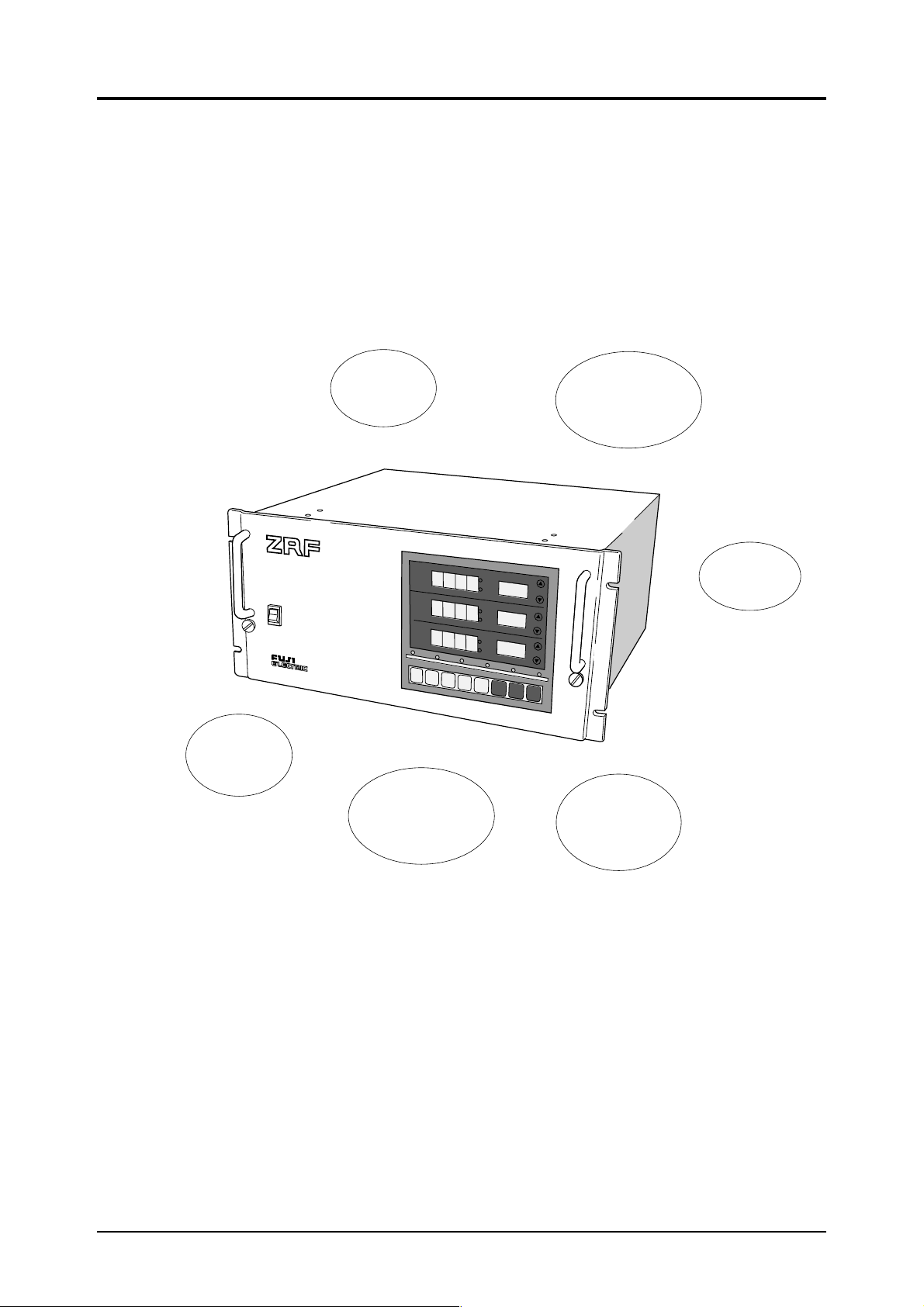
1. OUTLINE
This is a multi-function, easy-to-operate non-dispersion type infrared gas analyzer for measuring the
concentration of gases such as NO, SO
featuring high sensitivity and reliability, plus a microprocessor for easy operation.
, CO2 and CO. It utilizes a highly reputed mass flow type detector
2
INFRARED GAS ANALYZER
PO
Auto
calibration
function
(option)
Self diagnosis
function
Zero point
and span easily
adjustable by
key operation
NO
W
ER
ON
OFF
MEAS
FUNC
SO
O
2
2
MEAS
COMP
Remote range,
range detect
function
(option)
v
o
l%
p
p
m
R
A
N
G
E
v
o
l%
p
p
m
R
A
N
G
E
vol%
ppm
R
A
N
G
SPAN
HOLD
>
∧
E
N
T
Z
E
R
M
T
R
A
N
G
E
AUTO CAL
E
R
O
S
P
A
N
C
A
L
Upper/lower
limit alarm
function
(option)
Output hold
function
1
Page 9

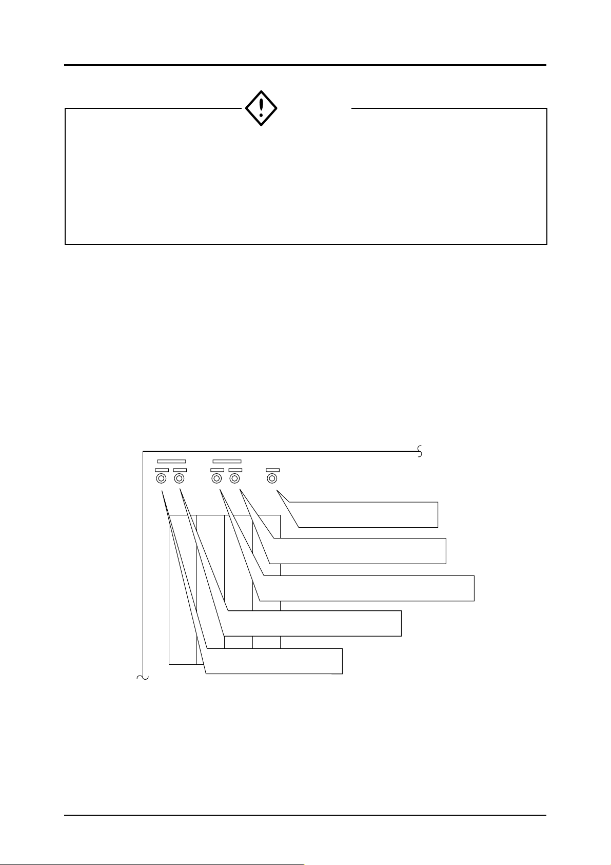
2. NAME AND DESCRIPTION OF EACH COMPONENT
2.1 Name and description of each component on case
INFRARED GAS ANALYZER
① Grip
② Knurled knob
POWER
ON
OFF
NO
SO
O
2
MEAS
F
U
N
C
③ Power switch
④ Indication/operation panel
* *
⑧ Reference gas inlet
⑦ Sample gas outlet
⑥ Sample gas inlet
2
MEAS
C
O
M
P
>
v
o
l%
p
p
m
v
o
l%
p
p
m
v
o
l%
p
p
m
SPAN
HOLD
RMT RANGE
∧
ENT
ZERO
Front panel
SPAN
R
A
N
G
E
R
A
N
G
E
R
A
N
G
E
AUTO CAL
CAL
⑨ Reference gas outlet
⑩ Purge gas inlet
*Used for differential
flow system only.
⑪ COMP1 (1st component)
input/output terminal
⑫ COMP2 (2nd component)
input/output terminal
⑬ O2 input/output terminal
(option)
SUMPLE GAS
INLET
OUTLET
COMP1 COMP2 O2 AUTO CAL
PLUG
Infrared
Gas Analyzer
Type
Range
Output
DC mA
Power Supply AC v 50/60Hz
Mid
Ser No.
Fuji Electric Co., Ltd
Rear panel
⑮ Power terminal
Japan
⑭ AUTO CAL input/output
terminal (option)
2
Page 10
Part name
① Grip
② Knurled knob
③ Power switch
④ Indication/operation panel
⑤ Flowmeter (option)
⑥ Sample gas inlet
⑦ Sample gas outlet
⑧ Reference gas inlet
⑨ Reference gas outlet
⑩ Purge gas inlet
⑪ COMP1 (1st component)
input/output terminal
⑫ COMP2 (2nd component)
input/output terminal
⑬ O2 input/output terminal
(option)
⑭ AUTO CAL input/output
terminal (option)
⑮ Power terminals
Description
Used to pull out the interior (base).
Used to fasten the instrument and case.
Turn ON to supply power to the internal components (excluding the pump).
After 3 or 4 seconds the LED indicator lights up. (Refer to 4.2 for pump
power supply.)
Indicates gas concentration, measuring range, etc., and contains keys necessary for routine operation and settings. Refer to section 5 for operating
method.
Used to check sample gas flow rate. Float rises when sample gas flows.
Connect gas to be measured here.
Connect pipe for discharging measured gas here.
Connect reference gas here in case of differential flow system.
Connect pipe here for discharging reference gas.
Connect pipe for purge gas here.
Used for 1st component of standard type and sample switching type or flow
differential type.
Input/output terminal for 2nd component of two-component analyzer.
Input/output terminal for O2 analyzer.
Input/output terminal for auto calibration function.
Supply power to the analyzer.
3
Page 11

2.2 Name and description of components on indication/operation panel
3 Unit indication lamp
2 Main indication
1 Component indication
7 Function indicator lamp
9 Component selector key
10
Digit shift key
11
Numeric input key
8 Function key
SU
TU TH
NO
SO
2
O
2
MEAS CAL SET ALH SET HOLD RMT RANGE AUTO CAL
COMP
FUNC
> ∧
vol%
ppm
MO WE FR
vol%
ppm
vol%
ENT ZERO SPAN CAL
SA
RANGE
RANGE
RANGE
(Three components of NO, SO2 and O2 are
indicated in this figure.)
4 Day indication
5 Sub indication
6 Range changeover key
15
Calibration start key
14
Span calibration key
13
Zero calibration key
12
ENT key
4
Page 12
Part name
① Component indication
② Main indication
③ Unit indication lamp
④ Day indication
⑤ Sub indication
⑥ Range changeover key
⑦ Function indicator lamp
⑧ Function key
⑨ Component selector key
⑩ Digit shift key
⑪ Numeric input key
⑫ ENT key
⑬ Zero calibration key
⑭ Span calibration key
⑮ Calibration start key
Description
Indicates kind of gas measured.
Indicates measured concentration. Also indicates various setpoints for alarm
function, auto calibration function (option), etc.
Indicates unit of measured gas concentration.
Indicates current day or day of starting by means of bar in auto calibration
(option) setting mode.
Indication SU MO TU WE TH FR SA
Day Sun Mon Tue Wed Thu Fri Sat
Indicates measuring range, error code, various setpoints, etc.
Used when changing the range. High range is set when pressing and low
range is set when pressing .
Relevant lamp lights up when following functions are set.
MEAS : Lights up in measuring status.
CAL SET : Flashes in calibration concentration setting mode.
ALM SET : Flashes in alarm setting mode.
HOLD : Flashes in hold setting mode or lights steadily while hold
function is activated.
RMT RANGE : Flashes in remote range setting mode or lights steadily while
remote range function is activated.
AUTO CAL : Flashes in auto calibration setting mode or lights steadily
while auto calibration function is activated.
Setting mode is changed at each press of this key. (Refer to section 5.)
Set component is changed for each setting mode or span adjustment.
Shift is made from highest toward lowest digit at each press of this key.
Selected digit is incremented at each press of this key.
By pressing this key after setting, the set contents are memorized and become
valid.
Used for zero point calibration. (Lamp flashes in zero calibration mode.)
Used for span calibration. (Lamp flashes in span calibration mode.)
Start key for manual calibration.
Zero is calibrated by pressing ZERO and CAL keys.
Span is calibrated by pressing SPAN and CAL keys. (CAL lamp lights
steadily during calibration.)
5
Page 13
3. INSTALLATION
• This unit is not explosion-proof type. Do not use it in a place with explosive gases to
prevent explosion, fire or other serious accidents.
• This unit is heavy and should be mounted securely to prevent it from falling.
Before mounting the unit, make sure that all the knobs on the front of the unit are fixed firmly.
•
3.1 Mounting method
DANGER
CAUTIONS
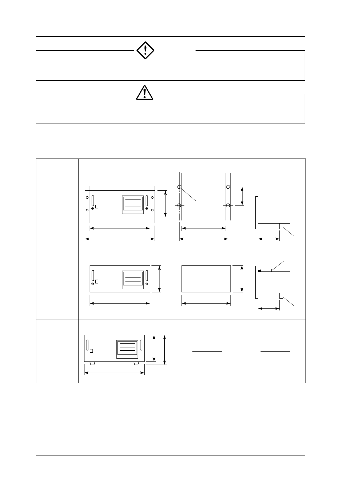
The following three methods are usable for mounting the analyzer.
Type Outer dimensions of analyzer Mounting dimensions Mounting method
19 inch
rack
mounting
Panel
mounting
ZRF
ZRF
443
483
443
220
<Panel output dimensions>
220
M6
438 or more
465
436
+2
–0
146
+2
213
240 or
more
–0
240 or
more
(Unit: mm)
Support
Mounting
bracket
Support
ZRF
Desk top
type
443
220
233
(1) Mounting method
Mount so that the front panel is vertical.
(2) Caution on installation
70% or more of the instrument weight should be supported by the case bottom.
(When mounting on a panel or 19 inch rack, attach a support under the rear of the case.)
6
Page 14
3.2 Piping method
DANGER
• Use clean pipes of which inside should not be stained with deposits of oil or fat.
• Piping joints must be tightened firmly to avoid gas leakage.
• Exhaust gas should be discharged to an outdoor safe place to prevent it from staying in the
sampling device and indoors.
• Exhaust from the analyzer should be relieved at the atmospheric pressure in order that an
unnecessary pressure will not be applied to the analyzer. Otherwise, any pipe in the
analyzer may be disconnected to cause gas leakage.
(1) Piping procedure
Connect pipes to the gas inlets and outlets located at the top left on the analyzer rear.
Use anticorrosive tubes made of Teflon, stainless steel, polyethylene or the like for connecting the
analyzer and sampling system. Avoid using rubber or soft vinyl tubes even if there is no worry about
corrosion. Improper piping material may cause inaccurate indication due to adsorption of gas.
The pipe connections are Rc1/4 (PT1/4) internal thread. And the pipes should be kept as short as
possible to quicken the response. A suitable inner diameter is about 4mm. Note that dust entering
the analyzer may cause a malfunction, so be sure to use clean pipes and joints.
Carry out gas piping as follows.
Purge gas inlet :
Connect purge gas pipe here.
Reference gas outlet :
Connect pipe here for discharging reference gas.
Reference gas inlet :
Connect reference gas here in case of flow differential system.
Sample gas outlet :
Connect pipe here for discharging measured gas.
Sample gas inlet :
Connect gas to be measured here.
7
Page 15
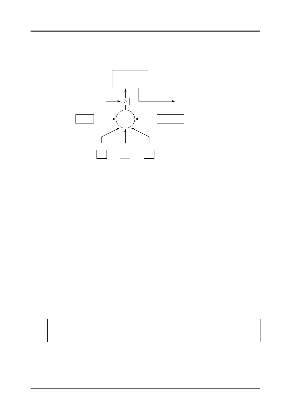
(2) Piping diagram
e
Shown next is an example of the configuration for measuring three components. (When using
Zirconia O
analyzer)
2
Gas analyzer
(ZRF)
Sample gas inlet
Flow meter
Air
(Zero calibration gas)
NO
Change
-over
valve
SO
(Span calibration gas)
Sample gas outlet
2
O
Arrange so that sample ga
outlet is at atmospheric pr
Sample gas
2
3.3 Sampling
3.3.1 Sample gas condition
(1) Remove all dust included in sample gas by means of a filter. Use a filter capable of eliminating
dust particles of 0.3µ at the final stage.
(2) The dew point of sample gas must be lower than the ambient temperature to prevent accumula-
tion of drain inside the analyzer. If water vapor is included in the sample gas, then feed the gas
through a dehumidifier to lower the dew point to around 0°C.
(3) If SO
(4) Note that if strongly corrosive gas such as Cl
(5) The sample gas temperature should range from 0 to 50°C. Be careful not to introduce a high
mist is included in sample gas, then use a mist filter, cooler etc. to exclude the mist. The
3
same applies if other kinds of mist are included.
, F2 or HCr is included in sample gas in a large
2
amount, it will shorten the service life of the analyzer.
temperature gas directly into the analyzer.
3.3.2 Sample gas flow rate
The sample gas flow rate should be as follows.
Provide a flowmeter as shown in the preceding diagram to measure the flow rate.
Standard type 0.5r±0.25r/minute
Sample switching type (1r+1r)±0.1r/minute (sample gas+reference gas)
Flow differential type (0.5r+ 0.5r)±0.25r/minute (sample gas +reference gas)
8
Page 16

3.3.3 Preparation of standard gas
Prepare standard gas for zero point and span point calibration.
Zero gas N2 gas
Span gas Gas with concentration of 80% or more of full scale for each component
(Span gas in measuring method is gas with concentration of 90% or more of full scale.)
When using a Zirconia O2 analyzer, use air for zero gas.
Zero gas Air (O2 analyser span gas in measuring method) Note)
Span gas 1 to 2% O2 (O2 analyser span gas in measuring method)
Gas with concentration of 80% or more of full scale for other than Zirconia O2 analyzer.
(Span gas in measuring method is gas with concentration of 90% or more of full scale.)
Note: When calibrating the low and high ranges of Zirconia type O2 analyzer, use 9 to 10% O2/N
for the low range, and air for the high range.
3.3.4 Analyzer interior purging
Although purging of the analyzer interior is normally unnecessary, it should be considered in the
following cases.
(1) When combustible gas is included in the measured gas
(2) When corrosive gas is included in the atmosphere at the installation site.
(3) When the same gas as the measured components is included in the atmosphere at the installa-
tion site.
In such cases, purge the analyzer interior with instrumentation air or N
should be about 1r/minute.
And dust or mist should be completely eliminated from the gas for purging.
3.3.5 Pressure at sample gas outlet
Arrange so that the sample gas outlet is at atmospheric pressure.
. The flow rate for purging
2
2
9
Page 17
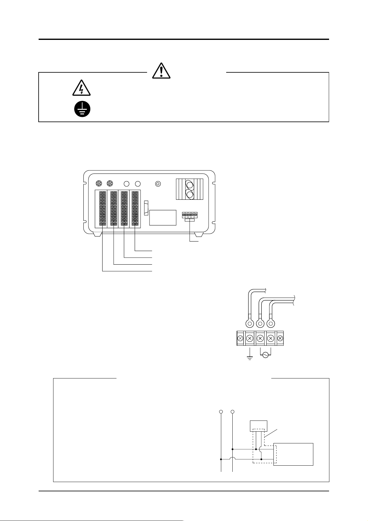
3.4 Wiring method
CAUTIONS
: Turn OFF all the power before starting a wiring work to prevent a risk of electric
shocks.
: Be sure to enforce construction of specified grounding.
The external terminals are provided on the rear of the instrument.
Carry out wiring to each terminal according to the figure. Terminal screws are M3.5 (but power
terminals are M4).
Use shielded wires for the output signals to suppress the influence of external noise.
3.4.1 Power terminals
The power terminals are arranged as shown in the figure.
Connect the specified power supply to the terminals and
connect a grounding wire to the ground terminal.
The grounding should be made securely.
Use solderless terminals (for M4) for connection to the
terminals.
Avoid installing this analyzer near an electrical apparatus which produces power source noise. (Such as
high frequency furnace, electric welder, etc.) If use of
the analyzer near such an apparatus is unavoidable,
then keep the power lines separate to avoid noise.
If noise from a relay, solenoid valve or the like enters
the power source, then attach a varistor or a spark
killer to the noise source as shown in the figure.
Note that attaching the varistor or spark killer away
from the noise source will be ineffective.
Power terminals (see 3.4.1)
Auto CAL input /output terminal (option) (see 3.4.5)
O
2
input/output terminal (option) (see 3.4.4)
COMP2 (2nd component) input/output terminal (see 3.4.3)
COMP1 (1st component) input/output terminal (see 3.4.2)
Source
E
When noise generating source is located nearby
ZRF
power supply
Varister or spark killer
Grounding wire
Power supply
Close connection
Noise
generating
source
10
Page 18
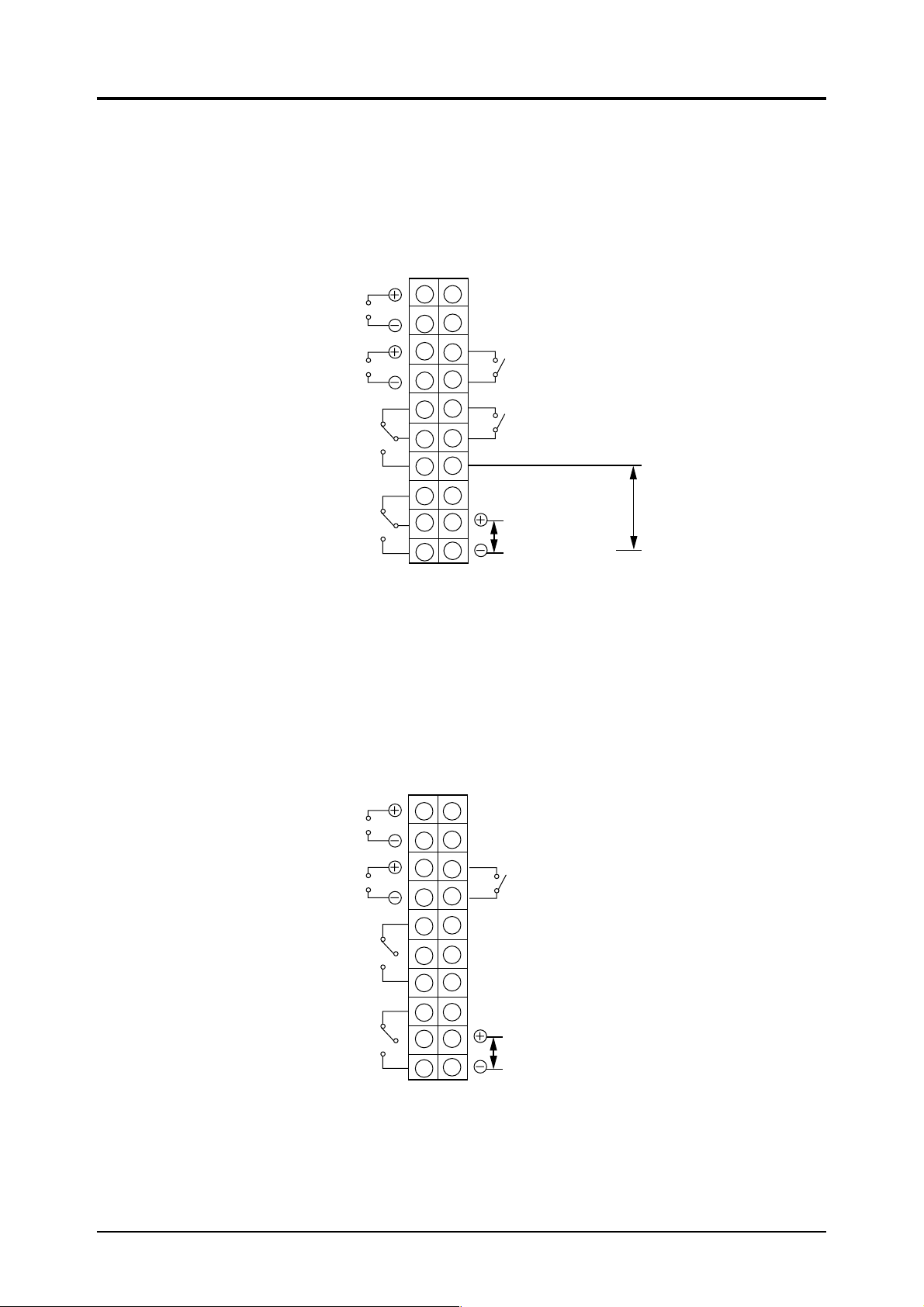
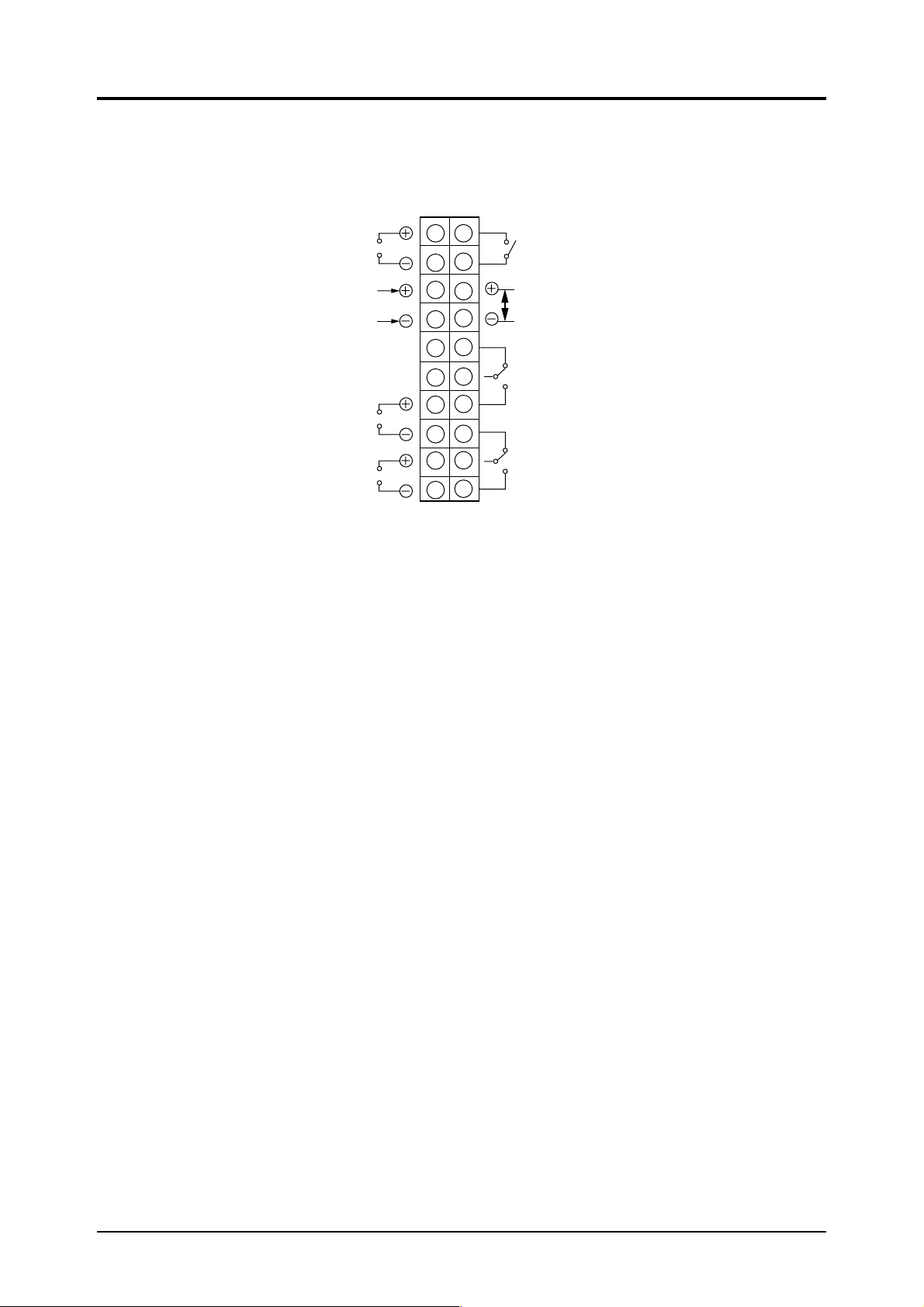
3.4.2 COMP 1 (1st component) input/output terminal
This output terminal is used with the standard single-component type, sample switching type or
flow differential type.
The wiring method is as follows.
Instantantaneous value
output signal
0 to 1V DC or
4 to 20mA DC
1
11
12
2
10
3
13
14
4
15
5
16
6
17
7
18
8
19
9
20
Range identification
contact output (option)
Fault
External hold input
(option)
Remote range
changeover signal
input (option)
Average value
output signal
0 to 1V DC or
4 to 20mA DC
(option)
Upper limit alarm
contact output
(option)
Lower limit alarm
contact output
(option)
3.4.3 COMP2 (2nd component) input/output terminal
This output terminal is for the 2nd component of the standard type.
The wiring method is as follows
Instantantaneous value
output signal
0 to 1V DC or
4 to 20mA DC
1
11
12
2
Average value
output signal
0 to 1V DC or
4 to 20mA DC
(option)
Upper limit alarm
contact output
(option)
Lower limit alarm
contact output
(option)
10
3
13
14
4
15
5
16
6
17
7
18
8
19
9
20
Range identification
contact output (option)
Remote range
input (option)
11
Page 19

COMP1, COMP 2 input/output terminal block
<Instantaneous value output>
Instantaneous value of 0 to 1V DC or 4 to 20mA DC is outputted.
<Moving average output> (option)
Specified 1 or 4 moving average value of 0 to 1V DC or 4 to 20mA DC is outputted.
<Upper limit alarm contact output> (option)
When signal exceeds upper limit, terminals ⑤ and ⑥ turn from ON to OFF and ⑥ and ⑦ turn from OFF
to ON.
1c contact 250V AC, 2A (resistive load)
<Lower limit alarm contact output> (option)
When signal is below lower limit, terminals ⑧ and ⑨ turn from ON to OFF and ⑨ ⑩ turn from OFF to
ON.
1c contact 250V AC, 2A (resistive load)
<Range identification signal output> (option)
Terminals ⑬ and ⑭ are conductive when 1st range is selected: ⑬ and ⑭ are open when 2nd range is
selected.
1a contact 250V AC, 2A (resistive load)
<Remote range input> (option)
1st range is selected when 5V DC is inputted to terminals ⑲ and ⑳ ; 2nd range is selected when there is
no input to terminals ⑲ and ⑳ .
<External hold input> (Input to COMP1 terminal) (option)
Hold setting component is outputted and held with 5V DC inputted between ⑲ and ⑳ .
<Fault> (Input to COMP1 terminal)
Contact output when analyzer incurs an abnormality.
1a contact 250V AC, 2A (resistive load)
12
Page 20
3.4.4 O2 input/output terminals (option)
This is the input/output terminal for the standard type O
2
The wiring method is as follows.
Instantantaneous value
output signal
0 to 1V DC or
4 to 20mA DC
O2 analyzer input
signal
0 to 1V DC
O
2
converted value
output signal
(1st component)
0 to 1V DC or
4 to 20mA DC
O
2
converted value
output signal
(2nd component)
0 to 1V DC or
4 to 20mA DC
input/output terminal block
O
2
1 11
2
3
4
5
6
7
8
9
10
12
13
14
15
16
17
18
19
20
Range identification
contact output (option)
Remote range
input (option)
Upper limit alarm
contact output
(option)
Lower limit alarm
contact output
(option)
<Instantaneous value output>
Instantaneous value of 0 to 1V DC or 4 to 20mA DC is outputted.
analyzer.
analyzer input signal>
<O
2
analyzer signal of 0 to linear 1V DC is inputted.
O
2
conversion output>
<O
2
conversion instantaneous value is outputted with preset conversion reference value.
O
2
<Upper limit alarm contact output> (option)
When upper limit is exceeded, terminals ⑮ and ⑯ turn from ON to off and ⑯ and ⑰ turn from OFF to
ON .
1c contact 250V AC, 2A (resistive load)
<Lower limit alarm contact output> (option)
When signal is below lower limit, terminals ⑱ and ⑲ turn from ON to OFF and ⑲ and ⑳ turn from OFF
to ON .
1c contact 250V AC, 2A (resistive load)
<Range identification contact output> (option)
Terminals ⑪ and ⑫ are conductive when 1st range is selected: ⑪ and ⑫ are open when 2nd range is
selected.
1a contact 250V AC, 2A (resistive load)
<Remote range input> (option)
1st range is selected when 5V DC is inputted to terminals ⑬ and ⑭ ; 2nd range is selected when there is
no input to terminals ⑬ and ⑭ .
13
Page 21

3.4.5 AUTO CAL input/output terminal (option)
This is the output terminal for the auto calibration function.
The wiring method is as follows.
1
10
11
12
2
3
13
14
4
15
5
16
6
17
7
18
8
19
9
20
Auto calibration
contact output
Zero gas contact
output
Span gas 1
contact output
Span gas 2
contact output
Span gas 3
contact output
AUTO CAL input/output terminal block (option)
<Contact output during auto calibration>
Contact between ① and ② is ON during auto calibration.
1a contact, 250V AC, 2A (resistive load)
Auto calibration
abnormal contact output
Remote start input
<Zero gas contact output>
Contact output for driving solenoid valve for flowing zero gas.
1a contact 250V AC, 2A (resistive load)
<Span gas 1 contact output>
Contact output for driving solenoid valve for flowing 1st component span gas.
1a contact 250V AC, 2A (resistive load)
<Span gas 2 contact output>
Contact output for driving solenoid valve for flowing 2nd component span gas.
1a contact 250V AC, 2A (resistive load)
<Span gas 3 contact output>
Contact output for driving solenoid valve for flowing O
analyzer span gas.
2
1a contact 250V AC, 2A (resistive load)
<Auto calibration abnormal contact output>
Contact output when abnormality occurs during auto calibration.
<Remote start input>
Input for starting auto calibration via external signal. Calibration started by inputting 5V DC between
terminals ⑬ and ⑭ .
14
Page 22

4. OPERATION
DANGER
• When handling the standard gas such as calibration gas, read the instruction manual of the
standard gas carefully and use the gas correctly.
CAUTIONS
• Avoid continuous operation with the casing drawn out.
• During operation, avoid opening the casing and touching the internal parts. Otherwise,
you may suffer a burn or shock hazard.
4.1 Operation procedure
Set up the operational status by the following procedure.
Operation is started by using the keys on the front panel of the analyzer. Before use, please read
through the instruction manual for the analyzer.
Mounting
Piping
Wiring
Check of piping
Purging inside alanyzer
Power switch on
Warming up
General Operation
Alarm value setting
Hold setting
Remote range setting
Automatic calibration setting
Concentration setting of
zero (air) point and span
calibration gas
Refer to Item 3.1.
Refer to Item 3.2.
Refer to Item 3.4.
Refer to Item 4.2 (1).
Refer to Item 4.2 (2).
Refer to Item 4.2 (3).
Refer to Item 4.2 (4).
Refer to Item 5.2 3).
Refer to Item 5.2 4).
Refer to Item 5.2 5).
Refer to Item 5.2 6).
Refer to Item 5.2 1)
to 2).
Carry out if needed.
Carry out if needed.
Zero/span calibration
Key lock ON/OFF setting
Intruduction of sample gas
(Start of measuring)
Refer to Item 5.2 8)
to 9).
Refer to Item 5.2 7).
Refer to Item 4.3.
15
Carry out if needed.
Page 23

4.2 Preparation for operation
(1) Check of piping
Check that piping has been made correctly.
(2) Purging of analyzer interior
When purging is necessary, then flow purge gas for about 3 hours before turning on power.
Purge gas
SAMPLE GAS
INLET INLETOUTLET OUTLET PURGE
(3) Turning on power
Turn on the power switch and indication will appear in a few seconds.
INFRARED GAS ANALYZER
POW
NO
ER
ON
OFF
O
M
E
FUNC
SO
A
S
2
2
COMP
M
E
A
S
vol%
ppm
vol%
ppm
vol%
ppm
S
P
A
N
H
O
L
D
RM
T RAN
ENT
ZERO
GE
SPAN
>
∧
(4) Turn on pump power supply
When the optional pump is provided, then pull out the base and turn on the pump power supply.
(5) Warmup
Flow the zero gas and warm up the instrument. The warmup is completed when the zero point
stabilizes (about 4 hours).
16
Page 24

(6) Concentration setting for calibration gas
Next set the concentration for the calibration gas.
Refer to 5.2 ① , ② for the procedure.
(7) Zero calibration
Flow zero calibration gas and calibrate the zero point. Refer to 5.2 ⑧ for the key operation for zero
calibration.
(8) Span calibration
Flow span calibration gas and calibrate the span.
Refer to 5.2 ⑨ for the key operation for span calibration.
4.3 Start of measurement
Flow the sample gas to start measurement.
4.4 Shutdown
Stop the flow of sample gas, and flow zero gas to purge the interior of the measuring cell.
Then turn off the power switch of the instrument.
When a pump is equipped, also turn off the pump power supply.
* The set values are retained in the memory even when power is turned off. But note that
with the clock function of the auto calibration function, the backup fails to work after 48
hours has elapsed, so when the power is turned on again, the correct time must be re-inputted.
CAUTIONS
Density below zero (indicated by a minus symbol) is displayed as zero.
When ZERO or SPAN key is pressed, this function is released to display minus value.
17
Page 25

5. OPERATION OF INDICATION/OPERATION PANEL
5.1 Outline of indication/operation panel
This panel consists of the following functions.
Function and key operation Main indication Sub indication Function lamp Page
(Option)
Measurement mode
FUNC
Setting of
calibration density
(O
2
zero setting mode)
and CAL>
Span setting mode
and CAL>
(Setting of single
zero calibration)
and CAL>
All/single range setting
FUNC
Alarm setting
and CAL>
Measured value
Zero point calibration density (with
zirconia O2)
Span point calibration density
(with O2 meter)
Range
Range
Range
Set value
Set value
Alarm value
MEAS lamp
ON
CAL SET
lamp ON
CAL SET
lamp ON
CAL SET
lamp ON
CAL SET
lamp ON
ALM SET
lamp flickers
20
22
22
23
23
27
Hysteresis setting
FUNC
Hold setting
(Option)
Remote range setting
FUNC
FUNC
To be continued to the next page.
Hysteresis
value
ON or OFF
ON or OFF
ALM SET
lamp flickers
Hold lamp
flickers.
RMT RANGE
lamp flickers.
28
29
31
18
Page 26

Function and key operation Main indication Sub indication Function lamp Page
(Option)
Auto calibration
Present time setting
FUNC
Auto calibration
start time setting
FUNC
Auto calibration
cycle setting
FUNC
Calibration gas
flow time setting
FUNC
Calibration gas
flow mode setting
FUNC
Auto calibration
selection
Hour & minute
Hour & minute
Day of week
Day of week
Time
Time
Mode No.
ON or OFF
AUTO CAL
flickers.
AUTO CAL
lamp flickers.
AUTO CAL
lamp flickers.
AUTO CAL
lamp flickers.
AUTO CAL
lamp flickers.
AUTO CAL
lamp flickers.
34
35
36
37
38
39
FUNC
Key lock selection
FUNC
Zero calibration ZERO CAL
Measured value
ON or OFF
Range
—
ZERO/CAL
40
key lamp
flickers.
Span calibration SPAN CAL
Measured value
Range
SPAN/CAL
key lamp
flickers.
• When the setting mode is assumed, the analog output signal is held at the value just before entering this
mode.
• When optional functions are not provided, the contents of these functions are not indicated.
19
Page 27

5.2 General operation
The measuring mode is assumed when power is turned ON.
The gas concentration appears on the main indication, while the range being used appears on the
sub indication.
NO
Gas concentration indication
• When selecting the range
In the setting status, as shown in
the figure at the right, the high
range is selected when
key is
pressed, while the low range is
selected when
When selecting the gas component.
•
key is pressed.
In the setting status, as shown in
the figure at the right, the gas
component can be set by pressing
COMP key.
Example:
When COMP key is pressed
while the 1st component is flashing, the flashing moves to the 2nd
component (Figure at the right).
The setting for the 2nd component
is now chageable.
COMP key is not provided for
*
single-component analyzer.
Advice on Operation
COMP
>
∧
By pressing this key, gas component to be set is selected.
Range indication
High range is selected by pressing this key.
Low range is selected by pressing this key.
No. 1 component
No. 2 component
No. 3 component
CAL
SPANZEROENT
20
Page 28

• For releasing zero or span
If a mistake has been made in zero
or span calibration, then perform a
reset in the following way.
The figure at the right shows an
example.
If SPAN key has been pressed
mistakenly instead of ZERO key,
press SPAN key again.
Calibration is cleared.
If ZERO key has been pressed
mistakenly instead of SPAN key,
press ZERO key again.
Calibration is cleared.
To clear moving average value,
press the
pressing the
key 3 times while
key in measure-
ment mode.
The data of each moving average
value is cleared.
SPANZERO
Key was pressed by mistake.
SPANZERO
Lamp flickers.
SPANZERO
Press the same key once again and the lamp will go off.
In this way, calibration is released, press Zero key.
21
Page 29

qq
q Calibration concentration setting (when not using Zirconia O2 analyzer)
qq
When not using a Zirconia O
analyzer, then set a span value for the calibration concentration
2
setting. (Zero point calibration concentration is fixed at zero.)
Set the calibration gas concentration (span value).
When FUNC key is pressed in the measuring status, the
previously set span value will appear on the main indication.
The CAL SET LED of the function indicating lamps will
flash.
By pressing the
key, the highest digit of the main
indication for the 1st component will flash, and the span
value can now be set.
Select a range with the
keys.
After selecting the range, set a span value in this status.
Then numeric value will be incremented by pressing
key.
The digit to be set can be selected by pressing
key.
For selecting the 2nd and subsequent components and
the range, press the
key and while the main
indication for the 1st component is flashing, press the
COMP
component to be set will flash. Now press the
key and then the main indication for the
keys to select the range to be set.
NO
FUNC
NO
CAL SET
>
NO
∧ >
NO
ENT
When the span value has been set, press the ENT key.
Setting operation is now completed.
Setting of single zero calibration:
This setting operation is used to select a zero calibration
component.
This function is invalid when O
component is not in-
2
cluded.
Press the
key in span setting mode.
The first digit in the main indication flickers.
NO
NO
>
NO
CAL
22
Page 30

Press the CAL key. “ ” appears in the main indication and “
At each press of the
order of “
” appears in the sub indication.
key, the setting is changed in the
→ → → ”.
After selecting, press the ENT key. The data is stored in
memory.
CAL
NO
∧
NO
= Meaning of set value =
Select
code
0 Calibration of all components Calibration of all components
1 Calibration of components other than O
2 Calibration of O
Manual calibration Auto calibration
2
Zero calibration
Calibration of components other than O
2
Note 1: This mode is invalid when O2 component is not included.
Note 2:
The main indication flickers when zero calibration ( ZERO + CAL ) is made on
selected components.
Setting of single calibration of all or each range:
This setting operation is used for calibration of all or each
NO
range during zero/span calibration.
Perform setting in the following way.
By pressing CAL key while the highest digit of the main
indication for the 1st component is flashing, then “
will appear on the main indication and “
” will appear on
”
NO
the sub indication.
Press
key and “ “ will change to “ ”.
ENT
2
CAL
∧
= Meaning of set value =
:The calibration is valid only for the selected range, and
zero and span calibration can be made independently
for each range.
: By conducting zero and span calibration for one range,
the calibration will be done automatically for the other
ranges as well.
Note 3: S.CAL “1” is interlocked with the range ratio
calibrated by “0” on each range.
Note 4: When a 1-range meter is used, be sure to set
S.CAL to “0”. If “1” is set, the result is the
same as “0”.
When the selection has been finished, press the ENT key.
23
NO
ENT
NO
Page 31

ww
w Calibration concentration setting (when using Zirconia O2 analyzer)
ww
When a Zirconia O
tion for each components of the O
analyzer is provided, set the zero (air) point and the span calibration concentra-
2
analyzer. Refer to 3.3.3. Preparation of standard gas for the
2
concentration of calibration gas to be used.
• Setting of calibration concentration for zero (air) point
The zero (air) point calibration concentration is settable
for the O
concentration for components other than for the O
analyzer alone. The zero point calibration
2
2
analyzer is fixed at zero.
By pressing the FUNC key in the measuring status, the
calibration concentration previously set for the zero (air)
point will appear on the main indication.
The CAL SET LED of the function indicating lamps will
flash.
By pressing the
main indication of the O
keys, the 2nd highest digit of the
analyzer will flash, and zero
2
point setting is enabled.
Press the
keys to select a range.
The numeric value will be incremented by pressing
key.
The digit to be set is selected by pressing
key.
Set the same air concentration for both high and low
range.
Press the ENT key after setting the zero point. Setting
operation is now completed.
O2
O2
O2
O2
FUNC
CAL SET
>
∧
ENT
>
Note: When using air for the high range and 9-10 vol % O
value of concentration for each range.
O2
for the low range, be sure to set the
2/N2
24
Page 32

• Setting of span calibration concentration
= Setting for each components =
Press the CAL key in the status where the digit of the O
analyzer main indication is flashing via the zero (air)
point calibration concentration setting.
The previously set span value will now appear on the
main indication.
The CAL SET LED of the function indicating lamps will
flash.
The highest digit of the 1st component main indication
will flash and the span value is now settable.
Press the
keys to select a range.
When the range has been selected, set a span value in this
status.
The numeric value will be incremented by pressing
key.
Press the
key and the digit to be set can be selected.
For selecting the 2nd and subsequent components and
the range, press the
key and in the status where
the 1st component main indication is flashing, press
the COMP key and the main indication for the component to be set will flash. Press the
keys to
select the range to be set.
2
O2
CAL
NO
∧
>
NO
ENT
NO
= Setting of O
analyzer =
2
NO
COMP
Press the ENT key after setting the span value. Setting
operation is now completed.
Setting of single zero calibration:
This setting operation is used to select a zero calibration
component.
This function is invalid when O
component is not in-
2
cluded.
Press the
key in span setting mode.
The first digit in the main indication flickers.
O
2
O
2
O
2
NO
NO
ENT
>
∧
>
25
Page 33

Press the CAL key. “ ” appears in the main indication and “
At each press of the
“ appears in the sub indication.
key, the setting is changed in the
CAL
NO
order of “
After selecting, press the ENT key. The data is stored in
→ → → ”.
∧
memory.
NO
= Meaning of set value =
Select
code
0 Calibration of all components Calibration of all components
1 Calibration of components other than O
2 Calibration of O
Manual calibration Auto calibration
2
Zero calibration
Calibration of components other than O
2
ENT
2
Note 1: This mode is invalid when O2 component is not included.
Note 2: The main indication flickers when zero calibration
( ZERO + CAL ) is made on selected components.
Setting of single calibration of all or each range:
This setting operation is used for calibration of all or each range during zero/span calibration.
Carry out the setting as follows.
By pressing CAL key while the highest digit of the 1st
components main indication is flashing, “
appear on the main indication and “
” will appear on the
” will
sub indication.
NO
CAL
Press key and “ ” will change to “ ”.
= Meaning of set values =
: The calibration is valid only for the selected range,
and zero and span calibration can be made independently for each range.
: By conducting zero and span calibration for one
range, the calibration will be done automatically for
the other ranges as well.
Note 3: S.CAL “1” is interlocked with the range ratio
calibrated by “0” on each range.
Note 4: When a 1-range meter is used, be sure to set
S.CAL to “0”. If “1” is set, the result is the
same as “0”.
Press the ENT key when the selection is finished.
Note: When using air for the high range and 9-10 vol % O
value of concentration for each range.
NO
∧
NO
ENT
NO
for the low range, be sure to set the
2/N2
26
Page 34

ee
e Alarm value setting (option)
ee
Set the upper and lower limit alarms and output an alarm.
Setting can be made for each component and each range.
Press FUNC key in the measuring status and “ ”
will be indicated.
The ALM SET LED of the function indicating lamps will
flash.
Press the
key and then alarm values are settable. The
highest two digits of the main indication will flash.
Contents of alarm value
setting indication
NO
:Upper limit
:Lower limit
:Lower range
:Upper range
FUNC
Setting value
:Plus
:Minus
Press the COMP key and select the gas component
for which alarms will be set.
Press
Press the
keys and select the range.
key to select either the upper or lower limit
alarm.
” indication appears when lower limit alarm is to
“
be set and “
” indication appears when upper limit
alarm is to be set.
Press the
key and the lowest digit flashes, so press the
key to select either plus “ ”or minus “ ”for the set
value.
A minus value should be set after releasing the alarm
function referring to the next page.
Press the
key and the highest digit of the main indication flashes, so set an alarm value. The numeric value is
incremented by pressing
Press the
key and the digit can be selected.
key.
NO
NO
NO
NO
NO
ALM SET
COMP
>
∧
>
∧
>
∧
ENT
>
)(
)(
When the alarm setting is finished, press the ENT key.
Setting operation is now completed.
NO
CAUTIONS
Alarm values are settable within the selected range. Setting is performed with the concentration
value.
Note that the upper limit alarm cannot be set below the lower limit alarm.
And if the lower limit alarm is set above the already memorized upper limit alarm, then the
upper limit alarm will become the same value as the newly set lower limit alarm.
27
Page 35

To make the alarm function invalid
For making the alarm function invalid, then set the upper limit alarm value to “
the lower limit alarm value to “
” for each component and each range.
NO
NO
Note: Use the following hysteresis setting as a reference when setting the hysteresis for the
alarm value.
Hysteresis setting
Set a hysteresis versus the alarm value.
Setting range of ±20% max.
ON
OFF
▲
Upper limit set value
Setting range of ±20% max.
ON
OFF
▲
Lower limit set value
” and
When CAL key is pressed in the alarm setting status, “
will appear on the main indication.
This is the mode for setting the hysteresis for the alarm value.
Change the hysteresis value on the sub indication by pressing
the
key.
The hysteresis is settable in 1% steps in a range of
±0 to ±20% versus the measuring range.
→
→
The indication changes from
→
→
→...........
..............
Press the ENT key when the setting is finished.
”
NO
CAL
NO
∧
NO
ENT
NO
28
Page 36

rr
r Hold setting
rr
This is used when calibrating for holding the output signal
at the value just before entering calibration. (The indication is not held.)
The hold function is settable for each component.
Set to OFF when not using.
Press the FUNC key in the measuring status and
“
” will be indicated.
The HOLD LED of the function indicating lamps will
flash.
Press the
key and the hold function will be settable.
The sub indication will flash.
Press the COMP key and select a setting
component.
Select hold “
” or “ ” by pressing the key.
Press the ENT key after setting the hold function. Setting operation is now completed.
At hold ON, the HOLD of the function indicating lamp
will light steadily while the hold functon is activated.
The unit indicating lamp flickers only for components
which have been set. This lamp goes off at hold OFF.
NO
NO
NO
NO
FUNC
HOLD
> ( )
∧
ENT
COMP
Note: Only the output will be held when this function is “
”, the indication is not held.
29
Page 37

Hold function
<Output hold functions after manual calibration>
The following shows the output hold function after manual calibration (zero or span).
The hold function is cleared automatically after 30 minutes or it can be cleared by key operation
(manual).
1. Operation
ZERO
Calibration
operation
Output hold
CAL keykey
30 min.
2. Clear operation
1) Auto clear
Press the ZERO key or SPAN key after hold setting (ON/OFF).
Output hold is started and calibration is completed with CAL key.
Then, the hold function is automatically cleared after 30 minutes.
2) Manual clear
The hold function is cleared manually by pressing the ENT key and CAL key at the same time.
Note 1: During auto calibration, the contact output between terminals ① and ② does not
operate when it is under manual calibration.
Note 2: Output hold is effective only for preset components.
<Output hold function under auto calibration>
Output hold function under auto calibration and replacement time. For operation, refer to Item ⑥ .
<External hold function> (option)
The following operation is used for output hold with external signals.
1. Operation
ON OFF
External signal
Output hold
2. Operation method
By putting 5V DC between the 1st component input/output terminals 17 and 20 (“+” and “-”),
only the component preset by the front key will be operated.
Note 1: The indication during operation is the same as that of hold calibration.
Note 2: This function is effective only when alarm, remote range or range detect function is
used as an option. (When using the supplied function, be sure to contact Fuji because
the hardware is different.)
Note 3: This function is effective only for the standard type No. 1 and 2 range analyzers and
flow differential type.
30
Page 38

tt
t Remote range setting (option)
tt
This is used for selecting the range via an external signal.
This setting should be OFF when remote range is not
used.
Press the FUNC key in the measuring status and
“
” will be indicated.
The RMT RANGE LED of the function indicating lamp
will flash.
Press the
key and the remote range function is
settable.
The sub indication will flash.
Select the remote range “
” or “ ” by pressing the
key.
The setting is valid for all the components.
Press the ENT key when the remote range setting is
finished. Setting operation is now completed.
FUNC
NO
RMT RANGE
>
NO
∧
NO
When the remote range function is set ON, the RMT
RANGE LED of the function indicating lamps will
remain lit, and the
keys will be unusable for range
selection.
• By inputting 5V DC between the remote input
terminals ⑬ and ⑭ , the No. 1 range is selected.
• No. 2 range is selected when 5V DC input is not
applied to the remote input terminals ⑬ and ⑭ .
ENT
NO
31
Page 39

;
;
;
;
;
;
;
;;;;;;;;;;;;
;
;
;
;
;
;
;
;
;;;;;;;;;;;;
;
;
yy
y Auto calibration (option)
yy
As an option with this analyzer, the signals from the input/output terminals on the rear panel can be
used for driving an external solenoid valve and introducing standard gas, whereby zero point and
span can be calibrated automatically.
The auto calibration is done according to ⑥ -1 current time setting, ⑥ -2 Auto calibration start
time, ⑥ -3 Auto calibration cycle, ⑥ -4 Calibration gas flow time, ⑥ -5 Calibration gas flow
mode, and ⑥ -6 Auto calibration ON/OFF setting.
Caution on operation
1. When the auto calibration start time is reached during key operation, the auto calibration is given
priority and is started. All key operation will be invalid until the auto calibration is finished.
To forcibly interrupt the auto calibration in progress, press both the ENT and CAL keys
2.
simultaneously. After the forcible interrupt, the measuring mode is resumed and all the keys are
operable. Although the current auto calibration will be passed over, it will be started from the
initially set cycle from the next time onward.
Example: When auto calibration is set for 3 hour intervals
starting from 8:00 a.m.
8:00
;;;;;;;;;;
11:00 14:00 17:00
;;;;;;;;;;;
;;;;;;;;;;;
;;;;;;;;;;
;;;;;;;
;;;;;;;
: Under auto
calibration
8:00
;;;;;;;;;;
;;;;;;;;;;
11:00 14:00 17:00
;;;
;;;
;;;;;;;;;;;
;;;;;;;;;;;
;;;;;;;;;;
;;;;;;;;;;
Manual interruption
3. Key operation is possible while calibration is not under way with the auto calibration function
set. Therefore all settings (of span, hold, remote range, time, etc.) including manual calibration
can be made. But note that if the wrong time is set on the clock, the auto calibration will not be
started at the correct time.
4. Auto calibration is able to start by applying remote start signal, 5V DC longer than 100m sec, to
remote start input terminals. In this case, auto calibration will start independent of its ON/OFF
setting.
32
Page 40

;
;
;
;
;
;
;
;
;
;
;
;
;;;
;
;
;
Gas flow time
;
Auto calibration
gas flow time
Example where auto calibration gas flow mode 5 is set
Auto calibration start time Auto calibration end time
Under
Under
mesurement
Under auto calibration
Zero gas
Span
gas 1
Span
gas 2
Span
gas 3
Substitution
TTTTT
T: Settable from 100 to 599 sec
mesurement
Next process
;;;;;;;;;;;;;;;;;;;;;
Gases introduced:
Sample gas
Zero gas
Span gas 1
Span gas 2
Span gas 3
Indicator lamps
AUTO CAL.
ZERO
SPAN
CAL
HOLD
(At HOLD ON)
;;;;;;;;;;;;;;;;;;;;
Auto calibration cycle
;;;;;;;;;;;;;;;;;;;;;;;;;;;;;;;;;;;;;;;;
;;;;;;;;;;;;;;;;;;;
;;;;;;;;;;;;;;;;;;;;
;;;;;;;;;;;;;;;;;;;
;;;;;;;;;;;;;;;;;;;
Flashes
;
Lights
;
;
Lights
;;;;;;;;;;;;;;;;;;;;;;;;;;;;;;;;;;;;;;;;;;;;;;;;;;;;;;;;;;;;;;;;;;;;;;;;;;;;;;;;;;;;;;;;;;;;;;;;;;;;;
Flashes
;;;;;;;;;;;;;;;;;;;
;;;;;;;;;;;;;;;;;;;;;;;;;;;;;;;;;;;;;;;;;;;;;;;;;;;;;;;;;;;;
Lights Lights Lights
;
Lights
;;;;;;;;;;;;;;;;;;;;;;;;;;;;;;;;;;;;;;;;;;;;;;;;;;;;;;;;;;;;;;;;;;;;;;;;;;;;;;;;;;;;;;;;;;;;;;;;;;;;;
Auto calibration abnormality:
If an abnormality occurs during auto calibration, a contact signal for auto calibration abnormality
will be outputted from the input/output terminals on the rear of the analyzer. The gas which incurred the abnormality will not be calibrated, and the next component will be calibrated instead .
33
Page 41

yy
y-1 Current time setting
yy
Set the current time and day of the week.
Press the FUNC key in the measuring status.
The AUTO CAL LED of the function indicating lamps
will flash.
NO
FUNC
SU TU TH
MO WE FR
SA
The main indication shows the hour and minute via
a 24-hour indication and the decimal point flashes.
bar lights up at the relevant weekday on the
A
sub indication.
Indication SU MO TU WE TH FR SA
Day Sun Mon Tue Wed Thu Fri Sat
Press the
key and the time is now settable. The
highest two digits of the main indication will flash.
The numeric value is incremented by pressing the
key.
Press the
After the time setting, press
key and the digit can be selected.
key and the day is
settable on the sub indication.
The bar indication will flash.
Press the
key and the bar will shift.
Press the ENT key when the time and day setting is
finished. The data is stored in memory.
Flashes
NO
NO
NO
>
>
ENT
∧
SU TU TH
MO WE FR
)(
∧
SU TU TH
MO WE FR
SU TU TH
MO WE FR
>
)(
AUTO CAL
SA
SA
SA
Time starts from the point where ENT key is
pressed.
34
Page 42

yy
A
y-2 Auto calibration start time setting
yy
When FUNC key is pressed at the current time indication, the auto calibration start time and day will appear on
the main and sub indications. The AUTO CAL LED of
the function indicating lamps will flash. In the case of
start time, the decimal point on the main indication will
light steadily.
Press the
key and the auto calibration start time is
settable, so set a start time on the main indication.
The numeric value is incremented by pressing the
key.
Press the
After setting the calibration start time, press the
key and the digit can be selected.
key
and the calibration start day can be set on the sub indication. The bar indication will flash.
Press the
key and the bar will shift.
The auto calibration start time is settable up to one
week ahead.
When the auto calibration start time and day have been
set, press the ENT key.
The data is stored in memory.
NO
Flashes
NO
NO
NO
NO
FUNC
>
>
ENT
SU TU TH
MO WE FR
SU TU TH
MO WE FR
∧
SU TU TH
MO WE FR
)(
∧
SU TU TH
MO WE FR
SU TU TH
MO WE FR
>
SA
SA
AUTO C
)(
SA
SA
SA
When the auto calibration at the set time is finished,
the next auto calibration start time will be set
automatically.
To confirm the next auto calibration start time, then
carry out this operation and check the indication.
Note: When the auto calibration start time has been set, then set the auto calibration cycle.
35
Page 43

yy
y-3 Auto calibration cycle setting
yy
The calibration cycle is settable in either ‘days’ or ‘hours’.
Press the FUNC key at the calibration start time indica-
tion and “
” will appear.
The AUTO CAL LED of the function indicating lamps
will flash.
Press the
key and the auto calibration cycle is
settable. The highest digit on the sub indication will flash.
Select either ‘days’ or ‘hours’ by pressing the
” appears on the sub indication when selecting
“
‘days’ and “
Press the
” appears when selecting ‘hours’.
key and the calibration cycle can be set in
the lower digits of the sub indication.
The numeric value is incremented by pressing the
key.
Press the
key and the digit can be selected.
key.
NO
NO
NO
NO
FUNC
( )
>
> ( )
∧
∧
>
AUTO CAL
Day is settable in a range of 1 to 7 days. Hour is
ENT
settable in a range of 1 to 99 hours.
NO
CAUTIONS
” (hours) is set, it will be automatically set to
If “
” (hour).
“
Press the ENT key when the calibration cycle has been
set. The data is stored in memory.
Note:When the auto calibration start time has been set, then set the auto calibration gas flow time.
36
Page 44

yy
y-4 Calibration gas flow time setting
yy
Press the FUNC key at the calibration cycle indication
and “
” will appear.
The AUTO CAL LED of the function indicating lamps
will flash.
Press the
key and the auto calibration gas flow time
is settable.
Set the flow time on the sub indication.
The numeric value is incremented by pressing the
key.
Press the
key and the digit can be selected.
NO
NO
FUNC
AUTO CAL
> ( )
∧
>
The setting range is 100 to 599 seconds.
NO
Press the ENT key when the calibration gas flow time
has been set. The data is stored in memory.
The times set in this mode is common to all the cali-
NO
ENT
bration gas flow time including replacement time.
Note: When the auto calibration start time has been set, set the auto calibration gas flow mode.
37
Page 45

yy
y-5 Calibration gas flow mode setting
yy
Select a calibration gas flow mode according to the number of components to be calibrated.
Press the FUNC key at the calibration gas flow time
indication and “
” will appear.
The AUTO CAL LED of the function indicating lamps
will flash.
Press the
key and the auto calibration gas flow time is
settable.
Set the calibration gas flow mode No. by pressing the
key.
(See the table below for the meaning of the flow mode
No.)
Press the ENT key when the calibration gas flow mode
has been set. The data is stored in memory.
NO
NO
NO
NO
FUNC
>( )
ENT
∧
AUTO CAL
Meaning of flow modes
Mode no. 1: Zero gas
Mode no. 2: Zero gas — 1st component
span gas
Mode no. 3: Zero gas — 1st component — 2nd component
span gas span gas
Mode no. 4: Zero gas — 1st component — 2nd component
span gas span gas (O
)
2
Mode no. 5: Zero gas — 1st components— 2nd component — 3rd component
span gas span gas span gas (O
)
2
Note: When all the settings for auto calibration have been finished, then select whether or not to
carry out auto calibration.
38
Page 46

yy
y-6 Auto calibration ON/OFF setting
yy
Select whether or not to carry out auto calibration.
Set to “
” when calibration will not be made.
NO
Press the FUNC key at the calibration gas flow mode
indication and “
” will be appear.
The AUTO CAL LED of the function indicating lamps
will flash.
Press the
key and auto calibration ON or OFF can be
set.
Select either “
pressing the
” or “ ” on the sub indication by
key.
When the auto calibration ON/OFF setting is finished,
press the ENT key.
Setting operation is now completed.
FUNC
NO
AUTO CAL
>
NO
∧
NO
ENT
NO
39
Page 47

uu
u Key lock ON/OFF setting
uu
This function is intended to prevent erroneous key operation.
By pressing the key lock at “ ” keys other than the
FUNC key will be inoperable.
To release the function, set at “
”.
NO
FUNC
Press the FUNC key in the measuring status and “ ”
NO
will be indicated.
Now press the
key and the key lock can be set.
>
The sub indication will flash.
NO
Set the key lock ON or OFF by pressing the key.
∧
NO
Press the ENT key when the key lock setting is finished.
Setting operation is now completed.
ENT
NO
Note: When the key lock is set at “ ” keys other than the FUNC key are inoperable.
40
Page 48

ii
i Zero calibration
ii
This is used for adjusting the zero point.
Flow the zero gas and wait until the indication stabilizes.
When the Zirconia O
analyzer is used, use air as the zero
2
gas. Note1)
When the indication has stabilized, select the measuring
range to be calibrated by using the
keys.
NO
ZERO
NO
When using a multi-component analyzer, undergo
zero calibration at the selected range and component.
Note 2)
Press the
ZERO
After the indication is stabilized, press the
key, and
ZERO
key lamp will flash.
CAL
key
NO
and conduct zero calibration.
The
CAL
key lamp lights steadily during calibration.
The calibration is completed when the key lamp goes off.
After the calibration, it is reset in measurement mode.
Calibrate other ranges as necessary.
CAUTIONS
Density below zero (indicated by a minus symbol) is displayed as zero.
This function is released by pressing
ZERO
key.
Flashes
CALSPANZEROENT
CAL
Lights steadily
CALSPANZEROENT
CALSPANZEROENT
(The lamp goes off after calibration)
Note 1: When using gas separately for low and high ranges, apply 9 to 10 vol% O
which has
2/N2
been set for low range.
Note 2: Calibration component should be set in zero calibration select mode.
Note 3: After zero calibration, change the range (2-range meter only) to confirm zero point of both
ranges being calibrated. When the indication of each range is not “Zero”, set S.CAL mode
to “0” and calibrate the zero point once again.
After it is calibrated, set S.CAL mode to “1”.
41
Page 49

oo
o Span calibration
oo
Carry out span calibration by flowing calibration gas at
the concentration set as a span value.
Flow the calibration gas at 0.5 r/minute.
Wait until the indication stabilizes, and then conduct span
calibration.
Press the
SPAN
key and the
SPAN
key lamp flashes.
NO
SPAN
NO
In the case of multi-component analyzer, the main
indication will flash for the components which can be
calibrated.
Press the COMP key and the calibratable gas component will change.
When the gas component has been determined, press
keys to select a range.
the
Note: The lamp will not flash in the case of a
single-component analyzer.
After the indication is stabilized, press the
CAL
key
and conduct span calibration.
The
CAL
key lamp lights steadily during calibration.
The calibration is completed when key lamp goes off.
Since the measuring status is resumed after calibration,
continue the calibration for each component and each
range.
( )
NO
NO
Flashes
CALSPANZEROENT
COMP
Flashes
CALSPANZEROENT
(In case of multicomponent analyzer)
CAL
Light steadily
CALSPANZEROENT
CALSPANZEROENT
(The lamp goes off after calibration)
CAUTIONS
Density below zero point (indicated by a minus symbol) is displayed as zero.
This function is released by pressing
Note 1: When a zirconia O
meter is used and zero point is calibrated by 9-10 vol % O2 for the low
2
SPAN
range, the zero and span calibrations interfere with each other. Therefore, each should be
calibrated a few times repeatedly.
Note 2: After span is calibrated, change the range (2-range meter only) to check the error or indica-
tion of each range. If it is large, set S.CAL mode to “0” and calibrate the span once again.
After it is calibrated, set S.CAL to “1”.
key.
42
Page 50

6. MAINTENANCE MODE
This mode should be used only for maintenance, inspection, repair or adjustment. When operation for
maintenance mode is required, contact our office in advance.
The maintenance mode refers to setting and adjustment in the following five modes.
• Response time setting mode (Refer to ① )
conversion reference value setting mode (option) (Refer to ② )
• O
2
• Optical balance adjustment mode (Refer to ③ )
• Interference compensation coefficient setting mode (Refer to ④ )
• Indication and clearing of drift amount integrated value (Refer to ⑤ )
>
NO
ENT
NO
NO
CAL
CAL
FUNC
Response
time setting mode
1. When O
setting mode is not available.
display, conversion function is not provided, O2 conversion reference value
2
NO
ENT
CAL
NO
CAL
NO
ENT
CAL
NO
ENT
Cautions on operation
FUNC
O2 conversion
reference value
setting mode
FUNC
Optical balance
adjustment
mode
FUNC
Interference
compensation
coefficient setting mode
FUNC
Clearing of drift amount
integrated value
Measurement mode
By pressing CAL key in the response time setting mode, the display is changed for optional balance adjustment.
2.
When any setting is finished, be sure to press ENT key.
If another key is pressed without pressing ENT key, the numerical value which has been
set is not registered.
3.
After ENT key is pressed, “ ” display lamp lights up.
43
Page 51

6.1 Response time setting
Press CAL key while “ ” display lamp is flickering,
and “
lamp flickers.
Press COMP key to select desired setting component.
Next, set the response time of the electric system.
Numerical value (1-199, O
displayed by the flicker of sub display lamp.
90% response time (electric system) ·=. 0.22 × (1-199)
sec.
” will be displayed. At this time, the sub display
: 1-49) is set from the top digit
2
NO
CAL
NO
∧
( )
NO
>
Numerical value increases by pressing
Digits are selected by pressing
After setting the response time, press ENT key.
key.
key.
6.2 O2 conversion reference value setting
With the “ ” indication flashing, press the CAL key
and “
The sub indication now flashes.
Set a reference value (1 to 19) %O
Press the
Press ENT key after setting a reference value.
” will be indicated.
key and the numeric will be incremented.
converted concentration
O
2
=
21 - Set value
(
21 - O
concentration
2
.
2
Note
× NOx concentration
(
NO
NO
NO
NO
ENT
CAL
∧
( )
Note: The maximum value to calculation is 4 .
ENT
NO
44
Page 52

6.3 Optical balance adjustment
When the sample cell is reassembled after having been detached for cleaning or the like, this
optical zero adjustment should be performed before use.
When this mode is assumed, the input signal from the measurement detector is displayed on
the main indicator while the input signal from the interference compensating detector is
displayed on the sub indicator.
The numerics vary in a range of -999 to 3200.
This adjustment is made so that the readings on both indicators approach zero. Refer to
section 7.2.3 “Optical zero adjustment method” for details.
With the “ ” indication flashing, press the CAL key
and the input signal from the measurement detector will
appear on the main indicator while the input signal from
the interference compensating detector will appear on the
sub indicator.
Press the CAL key after the optical balance adjustment.
NO
or
NO
CAL
NO
CAL
NO
CAUTIONS
A mistake in this adjustment will cause problems in measurement.
45
Page 53

6.4 Interference compensation coefficient setting
This is used for adjusting the interference compensation when there is much interference. In
this mode, adjust so that an indicated value is within 2% of gas concentration of full scale
while flowing interference gas (0°C or 2°C saturated H
ence compensation adjusting method” for details.
With the “ ” indication flashing, press the CAL key
and “
” will be indicated. Main display lamp “ ”
flickers.
(The compensation coefficient is the lower two digit on
the main indicator and a value within -32768 to 32768 on
the sub indicator.)
(The lower 2nd digit of main display is negative symbol.)
Press the COMP key to select the desired
component.
Set the compensation coefficient.
Press the
Press the
key and the numeric will be incremented.
key and the numeric will be decremented.
Press ENT key after setting the compensation coefficient.
O). Refer to section 7.2.4 “Interfer-
2
NO
CAL
NO
>
∧
( )
NO
ENT
NO
Note) In case the sub indication is a “–” one, the device
operates reversely.
CAUTIONS
A mistake in this adjustment will cause problems in measurement.
46
Page 54

6.5 Indication and clearing of integrated drift value
When the “ ” indication flashing, press the CAL key
and indicate the zero point drift amount on the main
indicator and the span point drift amount on the sub
indicator for each component.
Select the range with the
keys and the integrated zero
point and span point drift values will be indicated for that
range. (The indication is a % indication of gas concentration of full scale.)
When the integrated drift value appears, press the FUNC
key and the measurement mode will be resumed.
Range value
NO
NO
NO
CAL
( )
Integrated zero drift value
Integrated span drift value
ENT
FUNC
NO
Zero clearing
Carrying out zero clearing after cleaning the sample cell when the integrated drift value
appears on the indicator, press the ENT key and the integrated zero point and span point drift
values will be cleared to zero for each component and each range. The indicator will then
display “
”.
47
Page 55

7. MAINTENANCE
• When the inner case needs to open for adjustment of the optical system, etc., the inside of
the analyzer and the measuring gas line should be purged completely with zero gas to
avoid poisoning, fire or explosion due to gas leaks.
• Before working, take off a wrist watch, finger ring or the like metallic accessories. And
never touch the instrument with a wet hand, Otherwise, you will have a shock hazard.
• Do not use a replacement part other than specified by the instrument maker. Otherwise,
adequate performance will not be provided. Besides, an accident or fault may be caused.
• Replacement parts such as a maintenance part should be disposed of as incombustibles.
7.1 Routine maintenance
DANGER
CAUTIONS
(1) Zero and span calibration
① Carry out zero calibration with reference to the method in section 5.2.
② Next carry out span calibration with reference to the method in section 5.2.
③ Zero and span calibration should be made about once a week or when necessary.
(2) Check of flow rate
① The flow rates for sample gas, standard gas and purge gas are as follows.
• Sample gas and standard gas flow rates
Standard type analyzer 0.5±0.25r/minute (sample gas)
Sample switching type (1r+1r)±0.1r/minute (Sample gas + reference gas)
Flow differential type (0.5r+0.5r)±0.25r/minute (Sample gas + reference gas)
• Purge gas flow rate: about 1r/minute
② Inspection and maintenance should be carried out about once a day or as necessary.
48
Page 56

7.2 Periodical inspection
7.2.1 How to clean sample cell (pipe cell)
This instrument has been carefully adjusted before shipment from the factory. If it should require
readjustment, then please contact Fuji.
(1) Turn off the power switch, stop the flow of
sample gas and flow zero gas for a few
minutes.
Loosen the knurled knobs on the front
panel and pull out the analyzer interior by
means of the grips.
(2) Loosen the cap nuts fixing the gas inlet
pipe, and detach the internal gas inlet pipe.
(3) Remove the screws from the left and right
cell retaining places.
• In the case of the sample switching type,
remove both the sample and reference
cells.
• With the standard type, remove only the
sample cell.
Knurled
knob
Power switch
Knurled knob
Screw
Cell
retaining
plate
Cap nut
fixing gas
inlet pipe
Screw
Reference
cell
Sample cell
Cell
retaining
plate
Cap nut
fixing gas
inlet pipe
(4) Turn the retaining ring (with transparent
window) to the left and remove it from the
cell. Refer to Fig. 7-1.
(5) For cleaning the infrared-ray transmitted
window and cell interior, first remove
heavy contamination with a soft brush or
the like, then wipe lightly with a soft cloth.
Be especially careful when cleaning the
window since it is easily scratched.
O ring
Retaining ring
(6) When cleaning of the sample cell is finished, then reassemble the cell in its original position.
If the zero point has deviated considerably when operating again, select a low range and carry
out optical zero adjustment (refer to item 7.2.3).
Also, the drift integrated value should be cleared (see Item 6 ⑤ ).
CAUTIONS
If the infrared-ray transmitting window is only lightly contaminated, it can be cleaned by wiping
lightly with the soft cloth to which chrome oxide powder is added. But if heavily contaminated,
the window must be replaced.
Be careful not to apply unreasonable force when cleaning.
49
Page 57

7.2.2 How to clean sample cell (block cell)
(1) Turn off the power switch, stop the flow of
sample gas and flow zero gas for a few
minutes.
Loosen the knurled knobs on the front
panel and pull out the analyzer interior by
means of the grips.
Knurled
knob
Power switch
Knurled knob
(2) Loosen the cap nuts fixing the gas inlet
Cap nut fixing gas inlet pipe
pipe and remove the internal gas inlet pipe.
(3) Remove two detector
Note: Be careful since the distribution and
block cells are fixed together with
the detector.
Detector fixing screws
(4) Using the furnished cell assembly tool, turn
the retaining ring leftward and detach it
from the cell.
Refer to Fig. 7-2.
Retaining ring
Infrared-ray
transmitting window
Inner O ring
Outer O ring
O ring retainer
(5) For cleaning the infrared-ray transmitting window and cell interior, first remove heavy con-
tamination with a soft brush or the like, then wipe lightly with a soft cloth.
Be especially careful when cleaning the window since it is easily scratched.
(6) When cleaning of the sample cell is finished, then reassemble the cell in its original position.
If the zero point has deviated considerably when operating again, select a low range and carry
out optical zero adjustment (refer to item 7.2.3).
Also, the drift integrated value should be cleared (see Item 6. ⑤ ).
CAUTIONS
If the infrared-ray transmitting window is only lightly contaminated, it can be cleaned by
wiping lightly with the soft cloth to which chrome oxide powder is added. But if heavily
contaminated, then the window must be replaced.
Be careful not to apply unreasonable force when cleaning.
50
Page 58

*
Infrared-ray
transmitting window
Retaining ring
*
O ring
Sample gas inlet
Call
Gas inlet pipe fixing screw
Cap unt
Sample gas outlet
*
The infrared-ray transmitting
window and retaining ring are
attached with an adhesive.
Fig. 7-1 Sample cell structure
51
Page 59

Use the exclusive cells assembling tool (furnished).
Cell assembling tool
Retaining ring
O ring retainer
Outer O ring
Inner O ring
Infrared-ray transmitting window
Sample cell section
Sample cell structure (for cells with length of 32, 16, 8, 4, 2mm)
Sample gas inletSample gas outlet
Reference cell section
Bolt hole (for bolt which
fastens together distribution cell and detector)
(The sample cell and reference cell are integral.)
Fig. 7-2 Sample cell structure (block cell)
52
Page 60

7.2.3 Optical zero adjustment method (Optical balance method)
When the sample cell is reassembled after having been removed for cleaning or the like, this
adjustment should be carried out before use. Following is the adjustment procedure.
(1) First carry out electrical zero adjustment.
With the power turned off, detach the connectors CN2 and 3 (for 1st component) and CN4 and
5 (for 2nd component) leading from the detector which are connected with the main PCB (2).
Next, turn on the power and calibrate the zero point using ZERO and CAL keys.
(2) Turn off power, connect the connectors CN2 and 3 (1st component) and CN4 and 5 (2nd
component), and turn on power again. Supply dry nitrogen from the sample gas inlet and wait
until the indication stabilizes.
(3) Set up the optical zero adjustment mode as
in 6-3. The following indications will
NO
appear on the main and sub indicators of
the analyzer front panel.
Main indicator:
Input signal
from measurement
detector
(4) Operate the optical zero adjusting knob so
that the numeric value on the main indicator approaches zero (within ±10).
Optical zero
adjusting knob
Sub indicator:
Input signal
from interference
compensating detector
(5) Operate the dimmer plate so that the
numeric value on the sub indicator approaches zero.
Dimmer plate
(6) Repeat steps (4) and (5) to bring the numeric values on the main and sub indicators as close to
zero as possible.
CAUTIONS
A mistake in this adjustment will cause problems in measurement.
53
Page 61

7.2.4 Interference compensation adjusting method
Since this adjustment requires highly trained technique, please contact Fuji if it
becomes necessary.
Adjust the interference compensation if the effect of interference is large (more than ±2%FS of full
scale).
1) In case standard type and flow differential
type systems
(1) After warming up the instrument, supply
dry nitrogen at a rate of 0.5r/minute from
the sample gas inlet.
(With the flow differential system, supply
dry nitrogen continually to the reference
cell.)
(2) After indication is stabilized, carry out zero
calibration using the ZERO and CAL
keys.
Dry nitrogen 0.5r/min.
NO
CAL
NO
(3) Set up the interference compensation
setting mode as in section 6-4.
” will appear in the upper two digits of
“
the main indicator on the front panel while
a total of 5 numerals will appear in the
lower digit of the main indicator plus the
four digits of the sub indicator.
(A negative sign appears in the second
lowest digit of the main indicator.)
(4) Feed interference gas (saturated H
2
0°C or 2°C) as illustrated. When the
indication is stabilized, press COMP key
and select the component to be adjusted,
then adjust it until the indicated value
becomes almost 0 within 2% of the full
scale, using
key and key.
(5) After the adjustment is finished, press
ENT key to record the data in memory.
O at
COMP
NO
SO
>
∧
N2
Bubbler Cold water or
NO
Water
electronic cooler
Measured gas
inlet:
0 or 2℃
saturated H
2
O
54
Page 62

2) In case of sample switching system
(1) After warming up the instrument, supply
dry nitrogen at a rate of 1r/minute from
the measured gas inlet.
Detach the pipe from the reference cell gas
inlet (light source side) and flow dry
nitrogen at 1r/minute.
Carry out zero calibration using the ZERO
(2)
and CAL keys.
(3) Set up the interference compensation
setting mode as in section 6-4. “
appear in the upper two digits of the main
indicator on the front panel while a total of
5 numerals will appear in the lower digit of
the main indicator plus the four digits of
the sub indicator.
(A negative sign appears in the second
lowest digit of the main indicator.)
” will
Dry nitrogen 1r/min.
NO
CAL
>
∧
NO
NO
(4) Supply interference gas (0°C or 2°C
saturated H
O) as shown in the figure.
2
When the indication has stabilized, adjust
by using the
and keys so that the
indicated value approaches zero or within
2% of the value obtained by driving 30,000
by the range ratio.
When range ratio is 1 : 5 (low range :
high range)
1
30,000 ×
× 0.02 = 120
5
Adjust to obtain a value of nearly zero
within ±120.
(5) Return the reference cell pipe to its original
position.
N2
Water
Bubbler Cold water or
electronic cooler
Measured gas
inlet:
0 or 2℃
saturated H
2
O
55
Page 63

8. ERROR CODES AND REMEDIES
CAUTIONS
• If the cause of any fault cannot be determined despite reference to the instruction manual,
be sure to contact your dealer or Fuji Electric’s technician in charge of adjustment. If the
instrument is disassembled carelessly, you may have a shock hazard or injury.
• If the fuse is blown, eliminate the cause, and then replace it with the one of the same
capacity and type as before. Otherwise, shock hazard or fault may be caused.
This analyzer is provided with self-diagnosis function, and an error code is displayed if an abnormality
occurs in the instrument.
Carry out the following remedies when an error code appears.
• When an error code appears, first check for an abnormality in the power supply or gas piping.
• The analyzer will not operate correctly unless the cause of the error is removed. But, the error
indication remains as it is as a history until the ENT key is pressed.
56
Page 64

Error codes and countermeasures
Error code
E-0
E-1
E-3
E-4
E-6
E-8
E-5
E-7
E-9
E-10
E-11
E-16
E-23
Contents of error code
Trouble with digital
circuit (memory read/
write impossible)
Trouble with digital
circuit (output ic read/
write impossible)
Synchronizing signal
has stopped.
Zero point calibration
is out of the calibration range.
Integrated drift of
zero point exceeds
50%/FS of each
measurement range.
One-time zero point
calibration exceeds
50%/FS of measurement range.
Span point calibration
is out of calibration
range.
Integrated drift of
span point exceeds
50%/FS of measurement range.
One-time span point
calibration exceeds
50%/FS of measurement range.
Zero calibration is
impossible due to
unstable input.
Span calibration is
impossible due to
unstable input.
O2 input signal is low.
O2 input signal is over.
State of analyzer
Not operated until
trouble is removed.
• Both the
indicated value
and output value
have stopped.
• LED stops
flickering at each
setting.
Measurement is
possible but zero
calibration is
impossible.
Measurement is
possible but zero
calibration is
impossible.
Measurement is
possible but
calibration is
impossible.
Measurement is
possible but span
calibration is
impossible.
Measurement value
of O
analyzer is
2
different from
density.
Cause
• Malfunction due to
noise
• Digital circuit is
defective.
• Improper adjustment of
synchronizing signal
• Improper rotation of
motor and chopper
• Synchronizing signal
process circuit is
defective.
• Instantaneous power
failure
• Improper zero gas
• Unbalance of optical
system
• Optical system parts are
defective.
• Improper setting of
calibration set value and
cylinder
• Unbalance of optical
system
• Optical system parts are
defective.
• Abnormal sampling
system (improper gas
flow)
• Defective sensor
• Effect of vibration
• O2 sensor is defective.
• Input circuit is defective.
Check and countermeasure
• Turn ON the power supply.
When the analyzer operates
correctly, it is considered normal.
• Replace the main printed circuit
board.
• Adjust synchronizing signal on
main printed circuit board 2.
(CP1 - CS. VR1)
• Check motor and chopper for
proper rotation.
•
Check connector for proper
connection.
• Replace main printed circuit
board 2.
• Check gas components and dew
points.
• Check sampling system.
• Check the inside of cell for
contamination.
• Adjust the balance of optical
system.
• Replace light source.
• Replace sensor.
• Check calibration set value and
cylinder.
• Check sampling system.
• Check the inside of cell for
contamination.
• Adjust the balance of optical
system.
• Replace light source.
• Replace sensor.
• Check piping connection and
gas flow.
• Replace sensor.
• Check wiring and connector.
• Check operating conditions and
carry out vibration-proofing.
• Check O2 sensor output voltage
• Check wiring and connector.
E-17
E-24
1. Error code appears at the sub indication in the case of a single-component analyzer, and at the 2nd component sub indication
in the case of multi-component analyzer.
2. When multiple errors have occurred, the error codes appear successively starting from the lowest numbered one upon pressing
ENT key.
After displaying all the error codes, press ENT key again and the error display disappears, but they will reappear if the fault is
not removed.
3. Turn ON the power supply. When the analyzer operates correctly, it is considered normal.
4. When an error occurs, the FAULT contact output is conductive.
Temperature sensor
input signal is low.
Temperature sensor
input signal is over.
Measurement error
due to ambient
temperature may
become large.
• Temperature sensor is
defective.
• Temperature circuit is
defective.
• Check resistance of TMP 1 on
printing circuit board 2.
57
 Loading...