

Page 1
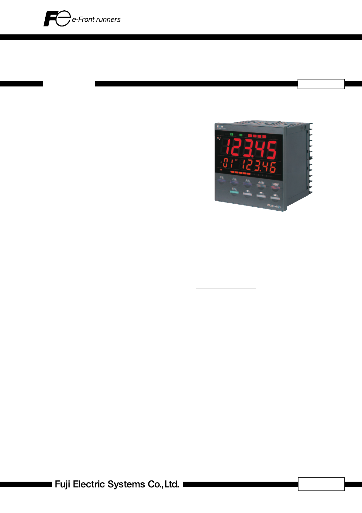
DIGITAL CONTROLLER PXH
DATA SHEET
PXH9 is a 96 × 96 mm, high-performance digital controller
that assures high-speed and high-accuracy control.
With its abundant and flexible input/output points and powerful math function, it can be used for a wide range of applications, including not only temperature control but also process control of pressure, flow rate, etc.
FEATURES
1. High-speed and high-accuracy control
• High-speed control in sampling cycle of 50 ms
• Highly accurate input indication of ±0.1% FS
•Measurement resolution of 0.01°C (Resistance
bulb input)
2. Multitude of input/output points (including options)
• Universal measurement input: 2 points
(Thermocouple/Resistance bulb/Voltage/Current)
• Auxiliary analog input: 1 point
(DC voltage/Potentiometer)
• Analog output: 2 points
• Digital input: 9 points
•Digital output: 9 points
• Transmitter power supply
3. Substantial communication function
• PC Loader interface (RS232C) equipped as standard
• RS485 (Modbus RTU) communication function
(Option)
4. Strong math function
• Applicable to various applications such as correction processing and input switching based on
mathematical calculations between multiple inputs. Refer to the list of expressions on page 17
for the type of mathematical expressions.
5. Complex setting achieved by easy operation
• Equipped with control template function that allows input/output according to control type and
automatic allocation of calculation blocks.
6. Totalizer function
• Input is selectable from any of measurements or
a result of math operation.
• Seven-digit total display
• Batch control outputs
7. Excellent user-friendliness
• Multi-function, large LED display with the high
level of visibility
• Provision of three function keys whose function
allocation can be changed
•IP66 waterproof front face (NEMA-4X)
• Compact size with the depth of only 81.5 mm
SPECIFICATIONS
1. General specifications
(1) Power supply voltage:
-
100 V (
50/60 Hz
(2) Power consumption:
15 VA or less (100 V AC)
20 VA or less (220 V AC)
(3) Insulation resistance:
20 MΩ or more (500 V DC)
(4) Withstand voltage:
Power supply ↔ All terminals;
Relay output ↔ All terminals;
Others; 500 V AC for 1 minute
(5) Applicable standard:
UL, C-UL, CE Mark
15%) to 240 V (+10%) AC,
1500 V AC for 1 minute
1500 V AC for 1 minute
PXH9
EDS11-157a
Date
Jan. 10, 2006
Page 2

PXH9
2. Input section
2-1 Measurement value input
(1) Number of inputs: 1 or 2 (Option)
(2) Input signal type:
Thermocouple :J, K, R, B, S, T, E, PR40/20, N, PL-II,
WRe5-26
Resistance bulb :Pt100Ω (3-wire)
Voltage :0 to 10 mV DC, 0 to 50 mV DC,
1 to 5 V DC, 0 to 5 V DC, 0 to 10 V DC
Current :4 to 20 mA DC, 0 to 20 mA DC
(3) Measurement range:
Refer to the measurement range table
(page 16).
(4)
Input indication accuracy (Ambient temperature: 23°C):
• Thermocouple:(±0.1%FS±1digit±1°C) or ±1.5°C,
whichever is larger
Thermocouple B: 0°C to 400°C range;
±5%FS±1digit±1°C
Thermocouple R: 0°C to 500°C range;
±1%FS±1digit±1°C
• Resistance bulb input:
(±0.1%FS±1digit) or ±0.25°C, whichever
is larger
• Voltage input, current input:
±0.1%FS±1digit
(5) Input sampling cycle: 50 ms
(6) Input impedance
• Thermocouple, voltage input (mV): 1 MΩ or more
• Voltage input (V): 1MΩ
•Current input: 250 Ω
(7) Influence of source resistance / Permissible wiring
resistance
• Thermocouple, voltage input (mV):0.1%FS per 100 Ω
• Voltage input (V): 0.1%FS per 500 Ω
• Resistance bulb input: 10 Ω or less (per cable)
(8) Permissible input voltage
• Voltage (V) input: +35 V /
•Current input: ±25 mA DC
•
Thermocouple/Resistance bulb/Voltage (mV) input:
(9) Noise reduction ratio
•Normal mode: 40 dB (50/60 Hz)
• Common mode: 120 dB (50/60 Hz)
(10) Input value correction function (Input conditioner)
• User adjustment:
±50%FS both for zero point and span
point
• Square-root extractor:
OFF or cut point from 0.0 to 125.0%
• First-order lag filter: 0.0 to 900.0 sec
• Linearizer: 16 straight lines
2-2 Auxiliary analog input (Option)
(1) Number of inputs: 1
(2) Input signal
1) DC voltage: 1 to 5 V DC / 0 to 5 V DC / 0 to 10 V DC
• Input accuracy: ±0.2%FS
• Sampling cycle: 100 ms
• Input impedance: 1 MΩ
• Influence of source resistance: 0.2%FS per 500 Ω
• Permissible input voltage: +35 V /
•Noise reduction ratio
• Normal mode: 40 dB (50/60 Hz) or more
• Common mode: 120 dB (50/60 Hz) or more
-
10 V DC
-
10 V DC
±5 V DC
2) Valve opening feedback signal (Potentiometer)
• Resistance range: 100 Ω ro 10 kΩ 3-wire
• Resolution: ±0.1%FS
• Input accuracy: ±1.0%FS
(3) Input value correction function
• User adjustment:
±50%FS both for zero point and span
point
• Square-root extractor:
OFF or cut point from 0.0 to 125.0%
• First-order lag filter: 0.0 to 900.0 sec
• Linearizer: 16 straight lines
2-3 Digital input (DI)
(1) Number of points:
Standard: 4 (Di1 to 4)
Expansion: 5 (9 points in total at max.)
(2)
Specifications:
(3) Contact capacity:
(4) Operation pulse width: 200 ms or more
(5) Function: Control mode changeover, EX-MV selec-
2-4 Math function
(1) Kind of formula:
(2)
Operation parameter:
(3) Data type: Engineering unit (with floating point)
3. Output section
3-1 Control output
3-1-1 Control output 1
(1) Number of points: 1
(2) Type: Select one from 1 to 4, as shown below.
1. Relay contact output
• Contact structure: SPDT contact (Do4 used)
• Contact capacity:
• Contact life: 100,000 operations (rated load)
2. SSR/SSC driver output (Voltage pulse)
• Rating: 12 V DC (10 to 15 V DC) / Maximum
• Load resistance:
3. Current output (4 to 20 mA DC)
• Accuracy: ±0.2%FS
• Linearity: ±0.2%FS
• Load resistance:
Contact or transistor input
12 V DC, Approx. 2 mA (per point)
tion, SV changeover, Control standby,
Auto-tuning start, Timer start, Alarm latch
cancel.
24 kinds, selected by the parameter setting. (see page 17.)
Analog input (PV1, PV2, Ai1),
Constant (K1 to K16)
220 V AC / 30 V DC, 3 A (Resistive load)
220 V AC / 30 V DC, 1 A (Inductive load)
current: 20 mA (provided with protection
against short circuit)
600 Ω or more
600 Ω or less
2
Page 3

4. Motorized valve operation pulse output (OPEN,
CLOSE output)
• Contact structure:
SPST contact x 2
(with interlock circuit)
• Contact capacity:
220 V AC / 30 V DC, 1 A
(Resistive load)
220 V AC / 30 V DC, 0.3 A
(Inductive load)
•
Contact life:100,000 times or more (rated load)
3-1-2 Control output 2 (Cooling output)
(1) Number of points: 1
(2) Type: Select one from 1 to 3, as shown below.
1. Relay contact output
• Contact structure: SPST contact (Do3 used)
• Contact capacity:
220 V AC / 30 V DC, 1 A (Resistive load)
220 V AC / 30 V DC, 0.3 A (Inductive load)
• Contact life: 100,000 operations (rated load)
2. SSR/SSC driver output (Voltage pulse)
• Rating: 12 V DC (10 to 15 V DC) / Maximum
current: 20 mA (provided with protection
against short circuit)
• Load resistance:
3. Current output (4 to 20 mA DC)
• Accuracy: ±0.2%FS
• Linearity: ±0.2%FS
• Load resistance:
3-2 Digital output (Do)
(1) Number of points:
(2) Specifications:
• Contact structure:
• Contact capacity:
• Contact life: 100,000 operations (rated load)
(3) Function: Alarm output, timer output, control out-
(4) Restriction: 4 Do points max. for 2-point measure-
(5) Others: Do4 or Do3 becomes control output
600 Ω or more
600 Ω or less
Standard: 2 (Do3, 4)
Expansion: Maximum 7 (9 points in total
at max.)
SPST contact (except for Do4)
SPDT contact (Do4)
220 V AC / 30 V DC, 1A (Resistive load)
put (Do4, Do3)
ment input model.
when relay is selected as control output.
Do4 becomes control output for motorized valve control type.
(4) Restriction: The sum of control output (current or
SSR/SSC drive), analog re-transmission
output and transmitter power supply
output is 2 points at maximum.
3-4 Transmitter power supply output
(1) Number of points: 1 at max.
(2) Rating: 24 V DC (17 to 30 V DC), Maximum cur-
rent; 23 mA (with short circuit protection)
(3) Restriction: The sum of control output (current or
SSR/SSC drive), analog re-transmission
output and transmitter power supply
output is 2 points at maximum.
4. Control function
4-1 Controller type
(1) Control system
• Advanced PID control with Auto-tuning
(2) Controller template
Operation block and I/O definition can be selected by parameter setting from available types according to targets of control.
• Basic type
1-loop basic PID controller (with math function)
1-loop SV selectable PID controller (with math function)
1-loop basic PID controller (without math function)
1-loop SV selectable PID controller (without math function)
1-loop input selectable PID controller (with math function)
• Motorized valve control type
[With or without valve openings feedback input is select-
able]
1-loop motorized valve controller (with math function)
1-loop SV selectable motorized valve controller (with math
function)
1-loop motorized valve controller (without math function)
1-loop SV selectable motorized valve controller (without math
function)
• Heating/cooling control type
1-loop heating/cooling controller (with math function)
1-loop SV selectable heating/cooling controller (with math
function)
1-loop heating/cooling controller (without math function)
1-loop SV selectable heating/cooling controller (without math
function)
Note:
The control template can only be changed within each of
basic type, motorized valve control type, and heating/cooling control type controllers.
3-3 Analog re-transmission output
(1) Number of points: 2 at max.
(2) Type: Current output (4 to 20 mA DC)
• Accuracy: ±0.2%FS
• Linearity: ±0.2%FS
• Load resistance
(3) Output contents:
:
600 Ω or less
PV, SV, MV, DV, AIM (Math operation
result), MVRB (Valve openings), TV
(Totarizer result)
3
Page 4

PXH9
4-2 Control parameter
4-2-1 Basic type, motorized valve control type
• Proportional band (P):
0.0 to 999.9%, ON/OFF (2-position)
operation at P = 0
• Integral time (I):
0.0 to 3200.0 sec, Integral operation OFF
at I = 0
•Derivative time (D):
0.0 to 999.9 sec, Derivative operation
OFF at D = 0
• Anti-reset windup: 0 to 100% of measurement range
• Proportion cycle:
1 to 150 sec, For SSR/SSC drive or relay
output only
• Hysteresis width:
50% of measurement range, for ON/OFF
operation only
• Control cycle: 50 ms
• Number of SV and PID groups: 7 sets
• Method of changing PID groups:
Selected by parameter, SV reference,
PV reference
4-2-2 Heating/cooling control type
• Proportional band on heating side (P): 0.0 to 999.9%
• Integral time on heating side (I):
0.0 to 3200.0 sec, Integral operation OFF
at I = 0
• Derivative time on heating side (D):
0.0 to 999.9 sec, Derivative operation
OFF at D = 0
• Proportional band on cooling side (Pc): 0.0 to 999.9%
• Integral time on cooling side (Ic):
0.0 to 3200.0 sec, Integral operation OFF
at Ic = 0
• Derivative time on cooling side (Dc):
0.0 to 999.9 sec, Derivative operation
OFF at Dc = 0
• Anti-reset windup: 0 to 100% of measurement range
• Proportion cycle:
1 to 150 sec, For SSR/SSC drive or relay
output only
• Hysteresis width:
50% of measurement range, for ON/OFF
operation only
• Control cycle: 50 ms
• Number of SV and PID groups: 7 sets
• Method of changing PID groups:
Selected by parameter, SV reference,
PV reference
4-3 Control mode
Type of mode:
(1)
(2) Changeover: Available via key, Digital input and Com-
Auto/Manual/Remote
munication.
Auto ↔ Manual: With balanceless,
bumpless transfer
Auto/Manual → Remote: With balance,
bumpless transfer
Auto/Manual ← Remote:
With balanceless,
bumpless transfer
5. Alarm function
5-1 Number of alarm points
• 8 points for setting
5-2 Type of alarm
• PV value (upper/lower limit, absolute/deviation, band), PV
variation ratio, SV upper/lower limit, main unit error
<Optional operation>
• Hold (standby) function
• Operation latching
• Excitation/non-excitation
• Operation delay: 0 to 9999 sec, 0 to 9999 min
5-3 Alarm output
• Output to DO1 to DO4 and DO11 to DO15 (Allocation
change available.)
6. Communication function
6-1 PC Loader interface
(1) Number of points: 1
(2) Physical specifications: EIA RS232C
(3) Protocol: Modbus-RTU
(4) Communication method:
3-wire, half-duplex bit serial asynchronous system
(5) Data type, Data length:
8 bits, Parity; Odd/Even/None
(6) Communication speed:
9600 bps, 19200 bps, 38400 bps
(7) Connector: Connected with miniature jack on bottom
face of the main unit (2.5 mm dia., 3-pole)
* Special cable is prepared as option.
6-2 RS-485 interface (option)
(1) Number of points: 1
(2) Physical specifications: EIA RS485
(3) Protocol: Modbus-RTU
(4) Communication method:
2-wire, half-duplex bit serial asynchronous system
(5) Data type, Data length:
8 bits, Parity; Odd/Even/None
(6) Communication speed:
9600 bps, 19200 bps, 38400 bps
(7) Connection topology:
Multi-drop, Up to 32 units can be connected including master device.
(8) Communication distance:
500 m max. (Total length of connection)
4
Page 5

7. Other functions
7-1 Parameter recipe
(1) Number of recipe groups: 7 sets
(2) Number of parameters which can be registered:
10 parameters
(3) Method of changing recipe groups:
Synchronized with the change of PID
groups
7-2 Totalizer
-
(1) Totalized value:
(2) Totalize source: PV1, PV2, Ai1, AiM [MATH result]
(3) Totalize resolution: XXX.XXXX to XXXXXXX
(4) Status: RUN/HOLD/RESET
(5) Totalized value output: via Re-transmission
(6) Alarm/Batch output: 2 points, via Do1 to Do4
(7) Totalized data backup:
8. Operation/display section
8-1 Parameter setting
• Digital setting by UP/DOWN key
• Key-lock function provided
• User function key (3 keys) provided
8-2 Display
(1) Type: LED
(2) Display contents
Measurement value display:
Setting display
Auxiliary display:
Bar graph: 12 segments (orange)
Status display indicator lamp:
9. Processing at power failure
• Memory protection: Non-volatile memory
10. Self diagnosis
• System: Program error monitoring performed by
11. Operation and storage conditions
(1) Ambient operating temperature:
(2) Storage temperature:
(3) Ambient humidity for use/storage:
(4) Warm-up time: 15 min or longer
1999999 to 9999999 (7 digits)
30 seconds interval to EEPROM
7 segments, 5 digits (red), character
height; 20 mm
: 7 segments, 5 digits (orange), character
height; 13 mm
7 segments, 2 digits (orange), character
height; 12 mm
Standby, control mode, output, alarm
watchdog timer
-
10°C to 50°C
-
20°C to 60°C
90% RH or less (non-condensing)
12. Structure
(1) Mounting method: Panel flush mounting
(2) External terminal: M3 screw terminal
(3) Case
• Material: Plastic
(Flame-resistant, UL94V-0)
• Color: Gray
(4) Protection
• Faceplate: IEC IP66, NEMA-4X-equivalent
(When mounted on panel with our genuine packing. Waterproof feature unavailable in side-by-side mounting.)
• Body: IEC IP20 (Provided with slits on top and
bottom faces)
• Terminal section:
IEC IP00. Terminal cover can be mounted
(option).
(5) External dimension:
96 (W) x 96 (H) x 81.5 (D) mm
* “D” is the depth from the front face of
the panel (not including terminal cover).
(6) Mass: Approx. 500 g
13. Range of delivery
• Controller …… 1 piece
• Instruction manual …… 1 piece
• CD-ROM …… 1 piece
Contents: User’s manual
Communication function manual
PC loader software
PC loader software manual
• Mounting bracket …… 2 pieces
• Waterproof packing …… 1 piece
• Terminating resistor …… 1 piece (only for the model
with communication function)
14. PC Loader Software
(1) System requirements
• PC: DoS/V PC (PC-AT compatible PC)
• Operation System:
Confirmed on
Windows 2000 (English)
Windows XP (English)
• RAM: 128MB or more
• HDD capacity (Empty area): 100 MB or more
• CD-ROM drive: Required
• Display resolution: 1024 x 768 dots or more
(2) Connection to the PXH controller
• Via PC Loader interface on bottom face of the main
unit (Optional dedicated cable is required.)
or
Via RS485 communication (RS485 function is necessary for PXH.)
5
Page 6
PXH9
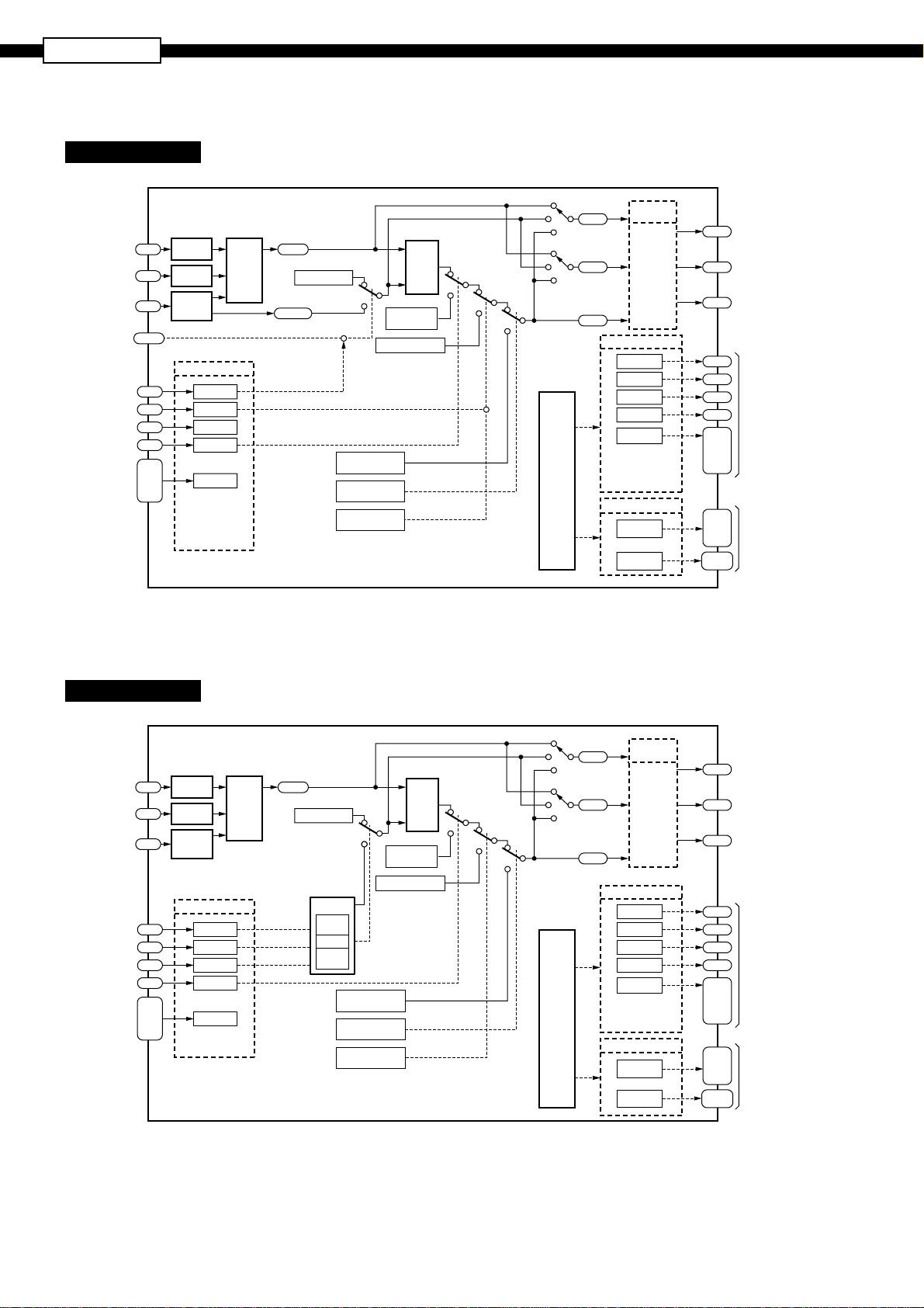
BLOCK DIAGRAMS
Template No. 10
Measurement
value
PV1
input 1
Measurement
value
input 2
Aux. input
/Remote
SV input
Remote
command
Remote
acknowledge
Manual
command
EX-MV
output
command
Conditioner
PV2
Conditioner
Ai1
Conditioner
[REM]
(Parameter setting or key operation)
Di1
Di2
Di3
Di4
Di11
to
Di15
(
CONTROLLER TEMPLATES
1-loop basic PID controller (with math function)
Result of
Math
module
calculation
[AiM]
Local SV
Remote SV
[RSV1]
Remote command
Remote
acknowledge
Input
Input
Input
Di allocation
R-ACK
SMV
No
allocation
EX-MV
command
No
allocation
* Di allocation can be
changed with para meters.
* Since the R-ACK
value is INH at the
time of delivery, set
it to ENA before use.
)
PV
PID
L
R
EX-MV output command
Preset output
value
[STBY] or
Di allocation
Manual
command
operation
SV
EX-MV setting
[EXM1]
Manual MV setting
A/M chargeover
[PMV1]
Stand-by
command
A/M chargeover
[Ao1T]
[Ao2T]
Re-trans-
mission
output 1
RET1
Re-trans-
mission
output 2
RET2
Control
output 1
MV1
* Do allocation can be
* Higher priority is
Output type
setting
Depend on
[OTYP]
setting
DO allocation
ALM1
ALM2
ALM3
ALM4
No
allocation
changed with
parameters.
assigned to designation
of [OTYP] for the
output to Do4.
LED display allocation
ALM
1 to 5
OR of all
the ALMs
AO 1
AO 2
DO 4
OUT1
OUT2
DO4
Do1
Do2
Do3
Do4
Do11
to
Do15
L Do1
to
L Do5
L ALM
Current
output or
SSR driver
output
Current
output or
Transmitter
supply
Relay
output
(Control
output)
Relay
output
(Do)
Indicator
lamp
PV
SV
MV
PV
SV
A
RUN
M
STBY
MV
Alarm
Template No. 11
Measurement
value
input 1
Measurement
value
input 2
Aux. input
SV select
signal 1
SV select
signal 2
SV select
signal 3
EX-MV
output
command
PV1
PV2
Ai1
Di1
Di2
Di3
Di4
Di11
Di15
to
Input
Conditioner
Input
Conditioner
Input
Conditioner
* Di allocation can be
changed with para meters.
1-loop SV selectable PID controller (with math function)
PV
[Ao1T]
SV
SV
MV
PV
MV
Alarm
[Ao2T]
Di allocation
SV select 1
SV select 2
SV select 3
EX-MV
command
No
allocation
Math
module
Result of
calculation
[AiM]
Local SV
SV select
SV1
[SV1]
SV7
[SV7]
to
Preset output
value
[STBY] or
Di allocation
command
PV
L
SV
EX-MV setting
R
Manual MV setting
EX-MV
output command
[PMV1]
Manual
PID
operation
[EXM1]
Stand-by
command
A/M chargeover
A
RUN
M
STBY
Re-trans-
mission
Output type
output 1
mission
output 2
Control
output 1
setting
Depend on
[OTYP]
setting
RET1
Re-trans-
RET2
MV1
DO allocation
ALM1
ALM2
ALM3
ALM4
No
allocation
* Do allocation can be
changed with parameters.
* Higher priority is
assigned to designation
of [OTYP] for the
output to Do4.
LED display allocation
ALM
1 to 5
OR of all
the ALMs
AO 1
AO 2
DO 4
OUT1
OUT2
DO4
Do1
Do2
Do3
Do4
Do11
to
Do15
L Do1
to
L Do5
L ALM
Current
output or
SSR driver
output
Current
output or
Transmitter
supply
Relay
output
(Control
output)
Relay
output
(Do)
Indicator
lamp
6
Page 7

Template No. 13
1-loop basic PID controller (without math function)
Measurement
value
input 1
Remote
SV input
Remote
command
Remote
acknowledge
Manual
command
EX-MV
output
command
PV1
Input Conditioner
Input Conditioner
Ai1
[REM]
(Parameter setting or key operation)
Di allocation
Di1
Di2
Di3
Di4
Di11
Di15
to
R-ACK
SMV
No
allocation
EX-MV
command
No
allocation
* Di allocation can be
changed with para meters.
* Since the R-ACK
value is INH at the
time of delivery, set
it to ENA before use.
Local SV
Remote SV
[RSV1]
Remote command
Remote
acknowledge
PV
L
R
PID
operation
SV
EX-MV setting
[EXM1]
Manual MV setting
A/M chargeover
EX-MV output command
Preset output
value
[PMV1]
Stand-by
command
[STBY] or
Di allocation
Manual
command
A/M chargeover
Alarm
Re-trans-
mission
[Ao1T]
output 1
RET1
Re-trans-
mission
[Ao2T]
output 2
RET2
Control
output 1
MV1
* Do allocation can be
* Higher priority is
LED display allocation
Output type
setting
Depend on
[OTYP]
setting
DO allocation
ALM1
ALM2
ALM3
ALM4
No
allocation
changed with
parameters.
assigned to designation
of [OTYP] for the
output to Do4.
ALM
1 to 5
OR of all
the ALMs
AO 1
AO 2
DO 4
OUT1
OUT2
DO4
Do1
Do2
Do3
Do4
Do11
to
Do15
L Do1
to
L Do5
L ALM
Current
output or
SSR driver
output
Current
output or
Transmitter
supply
Relay
output
(Control
output)
Relay
output
(Do)
Indicator
lamp
PV
SV
MV
PV
SV
A
RUN
M
STBY
MV
Template No. 14
Measurement
PV1
Di1
Di2
Di3
Di4
Di11
Di15
to
Input Conditioner
* Di allocation can be
changed with para meters.
value
input 1
SV select
signal 1
SV select
signal 2
SV select
signal 3
EX-MV
output
command
1-loop SV selectable PID controller (without math function)
[Ao1T]
[Ao2T]
Re-trans-
mission
output 1
RET1
Re-trans-
mission
output 2
RET2
Control
output 1
MV1
* Do allocation can be
* Higher priority is
LED display allocation
Di allocation
SV select 1
SV select 2
SV select 3
EX-MV
command
No
allocation
Local SV
SV select
SV1
[SV1]
to
SV7
[SV7]
L
R
Manual MV setting
EX-MV
output command
Preset output
value
[PMV1]
[STBY] or
Di allocation
Manual
command
PV
PID
operation
SV
EX-MV setting
[EXM1]
Stand-by
command
A/M chargeover
PV
SV
MV
PV
SV
A
RUN
M
STBY
MV
Alarm
Output type
setting
Depend on
[OTYP]
setting
DO allocation
ALM1
ALM2
ALM3
ALM4
No
allocation
changed with parameters.
assigned to designation
of [OTYP] for the
output to Do4.
ALM
1 to 5
OR of all
the ALMs
AO 1
AO 2
DO 4
OUT1
OUT2
DO4
Do1
Do2
Do3
Do4
Do11
to
Do15
L Do1
to
L Do5
L ALM
Current
output or
SSR driver
output
Current
output or
Transmitter
supply
Relay
output
(Control
output)
Relay
output
(Do)
Indicator
lamp
7
Page 8

PXH9
Template No. 16
Measurement
value
input 1
Measurement
value
input 2
Aux. input
Remote
command
PV select
RSV select
EXMV
select
FF select
FF INH
command
Remote
acknowledge
Manual
command
EX-MV
output
command
PV1
PV2
Ai1
key operation)
[REM]
[CN01]
[CN02]
[CN03]
[CN04]
[CN05]
Di1
Di2
Di3
Di4
Di11
to
Di15
(Parameter
setting or
(Parameter
(Parameter
EX-MV setting
(Parameter
(Parameter
(Parameter
Conditioner
Conditioner
Conditioner
setting)
setting)
[EXM1]
setting)
setting)
setting)
* Di allocation can be
changed with para meters.
* Since the R-ACK
value is INH at the
time of delivery, set
it to ENA before use.
1-loop input selectable PID controller (with math function)
Result of
Math
module
Remote
command
calculation
[AiM]
Remote
acknowledge
PV select
[CONST1]
L
Local
SV
R
RSV select
[CONST2]
EXMV select
[CONST3]
FF signal select
[CONST4]
FF
Calculation
Manual MV setting
A/M chargeover
EX-MV output command
PV
SV
AMV1
operation
value
Di allocation
PID
[FFv1]
Feedforward
Preset output
[PMV1]
[STBY] or
A
M
Stand-by
command
STBY
RUN
AIM
PV
SV
PV
SV
MV
AiM
MV
Alarm
Re-trans-
mission
output 1
[Ao1T]
RET1
Re-trans-
mission
[Ao2T]
output 2
RET2
Control
output 1
MV1
* Do allocation can be
changed with parameters.
* Higher priority is
assigned to designation
of [OTYP] for the output
to Do4.
Input
Input
Input
Di allocation
R-ACK
SMV
allocation
EX-MV
allocation
No
No
Output type
setting
Depend
on
[OTYP]
setting
DO allocation
ALM1
ALM2
ALM3
ALM4
No
allocation
LED display allocation
ALM
1 to 5
OR of all
the ALMs
AO 1
AO 2
DO 4
OUT1
OUT2
DO4
Do1
Do2
Do3
Do4
Do11
to
Do15
L Do1
to
L Do5
L ALM
Current
output or
SSR driver
output
Current
output or
Transmitter
supply
Relay
output
(Control
output)
Relay
output
(Do)
Indicator
lamp
8
Page 9

Template No. 30
1-loop motorized valve controller (with math function)
Measurement
value input 1
Measurement
value input 2
/Remote SV
input
Valve openings
feedback
signal
/Aux. input
Remote
command
Remote
acknowledge
Manual
command
EX-MV
output
command
AiM
PV
SV
MV
SV
MV
MVRB
AiM
PV
MVRB
Alarm
PV1
PV2
FB
/Ai1
[REM]
(Parameter setting
or key operation)
Di1
Di2
Di3
Di4
Di11
to
Di15
Input
Conditioner
Input
Conditioner
Input
Conditioner
module
Di allocation
R-ACK
SMV
No
allocation
EX-MV
command
No
allocation
* Di allocation can be
changed with para meters.
* Since the R-ACK
value is INH at the
time of delivery, set
it to ENA before use.
Math
Result of
calculation
[AiM]
Local SV
[RSV1]
Remote command
Remote
acknowledge
PV
L
R
PID
operation
SV
EX-MV setting
[EXM1]
A/M chargeover
EX-MV output command
Preset output
value
[PMV1]
Stand-by
command
[STBY] or
Di allocation
Manual
command
Front key
(during MAN
operation only)
A
RUN
M
STBY
* Valve openings feedback input is used for the type of 5th digit “D” in CODE SYMBOLS.
[Ao1T]
[Ao2T]
Control
output 1
MV1
Re-trans-
mission
output 1
RET1
Re-trans-
mission
output 2
RET2
Output type
setting
Depend on
[OTYP]
setting
PO
DO allocation
ALM1
ALM2
ALM3
No
allocation
* Do allocation can be
changed with
parameters.
* Higher priority is
assigned to designation
of [OTYP] for the
output to Do4.
LED display allocation
ALM
1 to 5
OR of all
the ALMs
AO 1
AO 2
OUT1
OUT2
CLOSE
OPEN
Do1
Do2
Do3
Do11
to
Do15
L Do1
to
L Do5
L ALM
Current
output
Current
output or
Transmitter
supply
Relay output
(Close output)
Relay output
(Open output)
Relay
output
(Do)
Indicator
lamp
Template No. 31
Measurement
value input 1
Measurement
value input 2
Valve openings
feedback
signal
/Aux. input
SV select
signal 1
SV select
signal 2
SV select
signal 3
EX-MV
output
command
PV1
PV2
FB
/Ai1
Di1
Di2
Di3
Di4
Di11
Di15
Conditioner
Conditioner
Conditioner
to
1-loop SV selectable motorized valve controller (with math function)
Input
Input
Input
Math
module
Di allocation
SV select 1
SV select 2
SV select 3
EX-MV
command
No
allocation
* Di allocation can be
changed with para meters.
Result of
calculation
[AiM]
SV select
SV1
[SV1]
to
SV7
[SV7]
Local SV
Remote
command
PV
PID
L
R
operation
SV
EX-MV setting
[EXM1]
EX-MV output command
Preset output
value
[PMV1]
Stand-by
command
[STBY] or
Di allocation
Manual
command
Front key
(during MAN
operation only)
A/M
chargeover
AiM
PV
SV
MV
AiM
PV
A
M
STBY
SV
MV
RUN
MVRB
MVRB
Alarm
[Ao1T]
[Ao2T]
Control
output 1
MV1
Re-trans-
mission
output 1
RET1
Re-trans-
mission
output 2
RET2
* Higher priority is
Output type
setting
Depend on
[OTYP]
setting
PO
DO allocation
ALM1
ALM2
ALM3
No
allocation
* Do allocation can be
changed with parameters.
assigned to designation
of [OTYP] for the
output to Do4.
LED display allocation
ALM
1 to 5
OR of all
the ALMs
AO 1
AO 2
OUT1
OUT2
CLOSE
OPEN
Do1
Do2
Do3
Do11
to
Do15
L Do1
to
L Do5
L ALM
Current
output
Current
output or
Transmitter
supply
Relay output
(Close output)
Relay output
(Open output)
Relay
output
(Do)
Indicator
lamp
* Valve openings feedback input is used for the type of 5th digit “D” in CODE SYMBOLS.
9
Page 10

PXH9
Template No. 33
Measurement
value input 1
Measurement
value input 2
Valve openings
feedback
signal
Remote
command
Remote
acknowledge
Manual
command
EX-MV
output
command
PV1
Conditioner
PV2
Conditioner
FB
Conditioner
〔REM〕
(Parameter setting
or key operation)
Di1
Di2
Di3
Di4
Di11
to
Di15
* Di allocation can be
changed with para meters.
* Since the R-ACK
value is INH at the
time of delivery, set
it to ENA before use.
* Valve openings feedback input is used for the type of 5th digit “D” in CODE SYMBOLS.
1-loop motorized valve controller (without math function)
PV
[Ao1T]
Input
Input
Input
Di allocation
R-ACK
SMV
No
allocation
EX-MV
command
No
allocation
Local SV
[RSV1]
Remote command
Remote
acknowledge
PV
PID
L
R
operation
SV
EX-MV setting
[EXM1]
A/M chargeover
EX-MV output command
Preset output
value
[PMV1]
Stand-by
command
[STBY] or
Di allocation
Manual
command
Front key
(during MAN
operation only)
SV
A
RUN
M
STBY
MV
PV
SV
MV
MVRB
MVRB
Alarm
[Ao2T]
Control
output 1
MV1
RET1
RET2
Re-trans-
mission
Output type
output 1
setting
Re-trans-
Depend on
mission
[OTYP]
output 2
setting
PO
DO allocation
ALM1
ALM2
ALM3
No
allocation
* Do allocation can be
changed with
parameters.
* Higher priority is
assigned to designation
of [OTYP] for the
output to Do4.
LED display allocation
ALM
1 to 5
OR of all
the ALMs
AO 1
AO 2
OUT1
OUT2
CLOSE
OPEN
Do1
Do2
Do3
Do11
to
Do15
L Do1
to
L Do5
L ALM
Current
output
Current
output or
Transmitter
supply
Relay output
(Close output)
Relay output
(Open output)
Relay
output
(Do)
Indicator
lamp
Template No. 34
Measurement
value
input 1
Valve
openings
feedback
signal
SV select
signal 1
SV select
signal 2
SV select
signal 3
EX-MV
output
command
Input
PV1
Conditioner
Input
FB
Conditioner
Di1
Di2
Di3
Di4
Di11
to
Di15
* Di allocation can be
changed with para meters.
* Valve openings feedback input is used for the type of 5th digit “D” in CODE SYMBOLS.
1-loop SV selectable motorized valve controller (without math function)
Re-trans-
[Ao1T]
MVRB
[Ao2T]
MVRB
MV1
mission
output 1
RET1
Re-trans-
mission
output 2
RET2
Control
output 1
PO
DO allocation
* Do allocation can be
changed with parameters.
* Higher priority is
assigned to designation
of [OTYP] for the
output to Do4.
LED display allocation
Output type
setting
Depend on
[OTYP]
setting
ALM1
ALM2
ALM3
No
allocation
ALM
1 to 5
OR of all
the ALMs
AO 1
AO 2
Di allocation
SV select 1
SV select 2
SV select 3
EX-MV
command
No
allocation
SV select
SV1
[SV1]
to
SV7
[SV7]
Local SV
Remote
command
PV
PID
L
R
operation
SV
EX-MV setting
[EXM1]
EX-MV output command
Preset output
value
[PMV1]
Stand-by
command
[STBY] or
Di allocation
Manual
command
Front key
(during MAN
operation only)
A/M
chargeover
PV
SV
MV
PV
A
M
STBY
SV
MV
RUN
Alarm
OUT1
OUT2
CLOSE
OPEN
Do1
Do2
Do3
Do11
to
Do15
L Do1
to
L Do5
L ALM
Current
output
Current
output or
Transmitter
supply
Relay output
(Close output)
Relay output
(Open output)
Relay
output
(Do)
Indicator
lamp
10
Page 11

Template No. 50
Measurement
value
input 1
Measurement
value
input 2
Aux. input
/Remote
SV input
Remote
command
Remote
acknowledge
Manual
command
EX-MV
output
command
Input
PV1
Conditioner
Input
PV2
Conditioner
Input
Ai1
Conditioner
[REM]
(Parameter setting or key operation)
Di allocation
Di1
Di2
Di3
Di4
Di11
to
Di15
* Di allocation can be
changed with para meters.
* Since the R-ACK
value is INH at the
time of delivery, set
it to ENA before use.
1-loop heating/cooling controller (with math function)
PV
[Ao1T]
SV
MV
PV
[Ao2T]
SV
MV
A
RUN
M
Heating
/cooling
operation
Stand-by
command
Heating
output
Cooling
output
RUN
STBY
RUN
STBY
R-ACK
SMV
No
allocation
EX-MV
command
No
allocation
Math
module
Result of
calculation
[AiM]
Local SV
Remote SV
[RSV1]
Remote command
Remote
acknowledge
PV
PID
L
R
operation
SV
EX-MV setting
[EXM1]
Manual MV setting
A/M chargeover
EX-MV output command
Preset output
value
value
Di allocation
[PMV1]
Preset output
[PMC1]
[STBY] or
RET1
RET2
HMV
CMV
Alarm
Re-trans-
mission
output 1
Re-trans-
mission
output 2
Heating
output
Cooling
output
Output type
setting
Depend on
[OTYP]
setting
DO allocation
ALM1
ALM2
ALM3
ALM4
No
allocation
* Do allocation can be
changed with para meters.
* Higher priority is
assigned to designation
of [OTYP] for the output
to Do3 and Do4.
LED display allocation
ALM
1 to 4
OR of all
the ALMs
AO 1
AO 2
DO 3
DO 4
OUT1
OUT2
DO3
DO4
Do1
Do2
Do3
Do4
Do11
to
Do15
L Do1
to
L Do5
L ALM
Current output
or SSR driver
output
Current output
or Transmitter
supply or SSR
driver output
Relay output
(Control output)
Relay output
(Control output)
Relay
output
(Do)
Indicator
lamp
Template No. 51
Measurement
value
input 1
Measurement
value
input 2
Aux. input
SV select
signal 1
SV select
signal 2
SV select
signal 3
EX-MV
output
command
PV1
PV2
Ai1
Di1
Di2
Di3
Di4
Di11
Di15
to
Input
Conditioner
Input
Conditioner
Input
Conditioner
* Di allocation can be
changed with para meters.
1-loop SV selectable heating/cooling controller (with math function)
Re-trans-
RET1
RET2
HMV
CMV
Alarm
mission
output 1
Re-trans-
mission
output 2
Heating
output
Cooling
output
Output type
setting
Depend on
[OTYP]
setting
DO allocation
ALM1
ALM2
ALM3
ALM4
No
allocation
* Do allocation can be
changed with parameters.
* Higher priority is
assigned to designation
of [OTYP] for the output
to Do3 and Do4.
LED display allocation
ALM
1 to 4
OR of all
the ALMs
Di allocation
SV select 1
SV select 2
SV select 3
EX-MV
command
No
allocation
Math
module
Result of
calculation
[AiM]
Local SV
SV select
SV1
[SV1]
to
SV7
[SV7]
PV
L
SV
EX-MV setting
R
Manual MV setting
EX-MV
output command
operation
[EXM1]
PID
A
M
Preset output
[PMV1]
value
Preset output
[PMC1]
value
[STBY] or
Di allocation
PV
SV
MV
PV
SV
MV
Heating
/cooling
operation
Stand-by
command
[Ao1T]
[Ao2T]
Heating
output
Cooling
output
RUN
STBY
RUN
STBY
AO 1
AO 2
DO 3
DO 4
OUT1
OUT2
DO3
DO4
Do1
Do2
Do3
Do4
Do11
to
Do15
L Do1
to
L Do5
L ALM
Current output
or SSR driver
output
Current output
or Transmitter
supply or SSR
driver output
Relay output
(Control output)
Relay output
(Control output)
Relay
output
(Do)
Indicator
lamp
11
Page 12

PXH9
Template No. 53
Measurement
PV1
value
input 1
Remote
SV input
Remote
command
Remote
acknowledge
Manual
command
EX-MV
output
command
Input Conditioner
Ai1
Input Conditioner
[REM]
(Parameter setting or key operation)
Di allocation
Di1
Di2
Di3
Di4
Di11
to
Di15
* Di allocation can be
changed with para meters.
* Since the R-ACK
value is INH at the
time of delivery, set
it to ENA before use.
1-loop heating/cooling controller (without math function)
RET1
RET2
HMV
CMV
Alarm
Re-trans-
output 1
Re-trans-
output 2
R-ACK
SMV
No
allocation
EX-MV
command
No
allocation
Local SV
Remote SV
[RSV1]
Remote
acknowledge
PV
PID
L
R
operation
SV
EX-MV setting
[EXM1]
Manual MV setting
A/M chargeover
EX-MV output command
A
M
Preset output
[PMV1]
value
Preset output
value
[PMC1]
[STBY] or
Di allocation
[Note 1]
Stand-by
command
SV
SV
PV
MV
PV
MV
Heating
/cooling
operation
[Ao1T]
[Ao2T]
Heating
output
Cooling
output
RUN
STBY
RUN
STBY
mission
Output type
setting
mission
Depend on
Heating
[OTYP]
output
setting
Cooling
output
DO allocation
ALM1
ALM2
ALM3
ALM4
allocation
* Do allocation can be
changed with para meters.
* Higher priority is
assigned to designation
of [OTYP] for the output
to Do3 and Do4.
LED display allocation
ALM
OR of all
the ALMs
No
1 to 4
AO 1
AO 2
DO 3
DO 4
OUT1
OUT2
DO3
DO4
Do1
Do2
Do3
Do4
Do11
to
Do15
L Do1
to
L Do5
L ALM
Current output
or SSR driver
output
Current output
or Transmitter
supply or SSR
driver output
Relay output
(Control output)
Relay output
(Control output)
Relay
output
(Do)
Indicator
lamp
Template No. 54
Measurement
PV1
Di1
Di2
Di3
Di4
Di11
to
Di15
Input Conditioner
Di allocation
SV select 2
* Di allocation can be
changed with para meters.
value
input 1
SV select
signal 1
SV select
signal 2
SV select
signal 3
EX-MV
output
command
1-loop SV selectable heating/cooling controller (without math function)
Re-trans-
RET1
RET2
HMV
CMV
Control
output 1
Alarm
mission
output 1
Re-trans-
mission
output 2
Heating
output
Cooling
output
Output type
setting
AO 1
[OTYP]
setting
AO 2
DO 3
DO 4
Depend on
DO allocation
ALM1
ALM2
ALM3
ALM4
No
allocation
* Do allocation can be
changed with parameters.
* Higher priority is
assigned to designation
of [OTYP] for the output
to Do3 and Do4.
LED display allocation
ALM
1 to 4
OR of all
the ALMs
SV select 1
SV select 3
EX-MV
command
No
allocation
Local SV
SV select
SV1
[SV1]
to
SV7
[SV7]
PV
L
SV
EX-MV setting
R
[EXM1]
Manual MV setting
EX-MV
output command
PID
operation
A
M
Preset output
value
[PMV1]
Preset output
value
[PMC1]
[STBY] or
Di allocation
PV
SV
MV
PV
SV
MV
Heating
/cooling
operation
Stand-by
command
[Ao1T]
[Ao2T]
Heating
output
Cooling
output
RUN
STBY
RUN
STBY
Current
output or
SSR driver
output
OUT1
Current output,
Transmitter supply,
OUT2
or
output
Relay output
DO3
(Control output)
Relay output
DO4
(Control output)
Do1
Do2
Do3
Do4
Do11
to
Do15
L Do1
to
L Do5
L ALM
SSR driver
Relay
output
(Do)
Indicator
lamp
12
Page 13

CODE SYMBOLS [Basic type]
Digit
<Dimension of front face H x W>
4
96 x 96 mm
<Number of control loops/Function>
5
1-loop basic controller
<Measurement value input>
6
Universal input: 1 point
Universal input: 2 points
<Auxiliary input>
7
Not fitted
DC voltage: 1 point
<Version No.>
8
<Output>
9
10
11
12
13
OUT1 OUT2
Current Not fitted
Current Current
Current Transmitter supply
SSR/SSC driver Not fitted
SSR/SSC driver Current
<Power supply>
100 to 240 V AC
<Communication interface>
Not fitted
RS-485
<Digital input/output>
Digital input Digital output (Including relay control output)
4 points (Di1 to Di4) 2 points (Do3, Do4)
4 points (Di1 to Di4) 4 points (Do1 to Do4)
9 points (Di1 to Di4, Di11 to Di15) 9 points (Do1 to Do4, Do11 to Do15)
<Additional specifications>
Not fitted.
Description
Notes
*1
*3
*2
*1
12345678
9
A
1
2
0
1
910111213
1V0PXH9A
1
A
B
Digit
1
2
5
V
0
R
0
A
B
0
*1: “2” for the 6th digit and “B” for the 12th digit cannot be specified at the same time.
*2: One digital output (Do4) is occupied when relay is allocated as control output.
*3: Explanation of the 9th digit of type code and output terminal function is below.
Code
9th
digit
Terminal
Output
Kind
Function
*
1
2
5
A
B
Do4
Relay
Control output
or
Digital output
* The selection of “Function” is specified according to the parameter.
(4 to 20 mA)
Control output
Re-transmission
Current
or
output
OUT1
SSR/SSC
driver
Control output
Current
(4 to 20 mA)
Re-transmission
output
Optional Items
Contents Model Notes
Terminal cover ZZP PXR1-B230 Two pieces are necessary per
PC loader interface cable ZZP PXH1*TK4H4563 For RS232C Interface
1 unit.
OUT2
Transmitter
power
supply
: Not fitted
: Fitted
13
Page 14

PXH9
[Motorized valve control type]
Digit
<Dimension of front face H x W>
4
96 x 96 mm
<Number of control loops/Function>
5
1-loop motorized valve controller (with valve openings feedback input)
1-loop motorized valve controller (without valve openings feedback input)
<Measurement value input>
6
Universal input: 1 point
Universal input: 2 points
<Auxiliary input>
7
Not fitted
DC voltage: 1 point
<Version No.>
8
<Output>
9
10
11
12
13
OUT1 OUT2
Current Not fitted
Current Current
Current Transmitter supply
<Power supply>
100 to 240 V AC
<Communication interface>
Not fitted
RS-485
<Digital input/output>
Digital input Digital output (Including valve control output)
4 points (Di1 to Di4) 2 points (Do3, Do4)
4 points (Di1 to Di4) 4 points (Do1 to Do4)
9 points (Di1 to Di4, Di11 to Di15) 9 points (Do1 to Do4, Do11 to Do15)
<Additional specifications>
Not fitted.
Description
Notes
*1
*2
*3
*1
12345678
9
D
S
1
2
0
1
1V0PXH9
1
910111213
1
2
5
V
0
R
0
A
B
Digit
0
*1: Universal input 2 points and “B” for the 12th digit cannot be specified at the same time.
Select “universal input 2 points” when external setting input (RSV) is required.
*2: “D” for the 5th digit and “1” for the 7th digit cannot be specified at the same time.
*3: Do4 is used as control output.
If 2 or 3 Do points are required for event output, specify code A, and if 4 to 8 Do points are required, specify code B.
OUT1
Current
(4 to 20 mA)
Re-transmission
output
OUT2
Current
(4 to 20 mA)
Re-transmission
output
Transmitter
power
supply
: Not fitted
: Fitted
Code
9th
digit
Terminal
Output
kind
Function
*
1
2
5
* The selection of “Function” is specified according to the parameter.
Do4
Relay
Used for
valve
open/close
output.
14
Page 15

[Heating/cooling control type]
9
4
5
6
8
7
9
10
11
12
13
12345678
1V0PXH9F
910111213
F
V
1
2
0
1
0
R
1
0
1
2
3
5
A
B
C
0
A
B
1
2
5
A
B
3
C
Digit
9th
digit
Code
Terminal
Output
kind
Function
*
Do3
Relay
Control output
or
Digital output
OUT1
Current
(4 to 20 mA)
Control output
or
Re-transmission
output
SSR/SSC
driver
Control output
OUT2
: Not fitted
: Fitted
* The selection of “Function” is specified according to the parameter.
<Dimension of front face H x W>
96 x 96 mm
<Number of control loops/Function>
1-loop heating/cooling controller
<Measurement value input>
Universal input: 1 point
Universal input: 2 points
<Auxiliary input>
Not fitted
DC voltage: 1 point
<Version No.>
<Output>
OUT1 OUT2
Current Not fitted
Current Current
Current SSR/SSC drive
Current Transmitter supply
SSR/SSC driver Not fitted
SSR/SSC driver Current
SSR/SSC driver SSR/SSC drive
<Power supply>
100 to 240 V AC
<Communication interface>
Not fitted
RS-485
<Digital input/output>
Digital input Digital output (Including relay control output)
4 points (Di1 to Di4) 2 points (Do3, Do4)
4 points (Di1 to Di4) 4 points (Do1 to Do4)
9 points (Di1 to Di4, Di11 to Di15) 9 points (Do1 to Do4, Do11 to Do15)
<Additional specifications>
Not fitted.
*3
*1
*2
*1
Notes
Digit
Description
*1: “2” for the 6th digit and “B” for the 12th digit cannot be specified at the same time.
*2: One digital output (Do4) or 2 points (Do3 and 4) is occupied when relay is allocated as control output.
*3: Explanation of the 9th digit of type code and output terminal function is below.
Current
(4 to 20 mA)
Control output
Control output
or
Digital output
Control output
or
Re-transmission
output
Relay
Do4
SSR/SSC
driver
Transmitter
power
supply
15
Page 16

PXH9
MEASUREMENT RANGE TABLE
(1) Unit of temperature : ˚C
Input type
Resistance bulb
Thermocouple
DC voltage
DC current
Motorized valve
opening feedback
Pt100Ω
J
K
R
B
S
T
E
PR40/20
N
PL-II
WRe5-26
1 to 5 V
0 to 5 V
0 to 10 V
0 to 10 mV
0 to 50 mV
4 to 20 mA
0 to 20 mA
Potentiometer
Measurement range [˚C]
Max. Min.
-
150 to 850
0 to 1000
0 to 1200
0 to 1600
0 to 1800
0 to 1600
-
200 to 400
-
200 to 800
0 to 1800
0 to 1300
0 to 1300
0 to 2300
-
19999 to 99999
(Range where scaling
is allowed)
100 to 10 kΩ
0 to 150
0 to 400
0 to 400
0 to 1600
0 to 1800
0 to 1600
-
200 to 200
0 to 800
0 to 1800
0 to 1300
0 to 1300
0 to 2300
Reading/setting
resolution (˚C)
0.01
0.1
0.1
0.1
0.1
0.1
0.1
0.1
0.1
0.1
0.1
0.1
1/10000
digit
1/1000
digit
(2) Unit of temperature : ˚F
Input type
Resistance bulb
Thermocouple
DC voltage
Current
Motorized valve
opening feedback
Pt100Ω
J
K
R
B
S
T
E
PR40/20
N
PL-II
WRe5-26
1 to 5V DC
0 to 5V DC
0 to 10V DC
0 to 10mV DC
0 to 50mV DC
4 to 20mA DC
0 to 20mA DC
Potentiometer
Measurement range [˚F]
Max. Min.
-
238 to 1562
32 to 1832
32 to 2192
32 to 932
32 to 3272
32 to 2912
-
328 to 752
-
328 to 1472
32 to 3272
32 to 2372
32 to 2372
32 to 4172
-
19999 to 99999
(Range where scaling is allowed)
100 to 10 kΩ
32 to 302
32 to 752
32 to 752
32 to 932
32 to 3272
32 to 2912
-
328 to 392
32 to 1472
32 to 3272
32 to 2372
32 to 2372
32 to 4172
Reading/setting
resolution (˚F)
0.01
0.1
0.1
0.1
0.1
0.1
0.1
0.1
0.1
0.1
0.1
0.1
1 / 10000
digit
1/1000
digit
16
Page 17

LIST OF MATH FUNCTIONS
CALC
setting
0 No math operation
Mathematical expression 1
(
Flow rate compensation with
1
temperature and pressure
Mathematical expression 2
Flow rate compensation with
(
2
temperature and pressure
Mathematical expression 3
3
Flow rate compensation with
(
temperature and pressure
4
Mathematical expression 4
5
Mathematical expression 5
Mathematical expression 6
6M
7
8
9
10
Input switching (2 points)
11
12
(with Di switching function)
13
(with Di switching function)
Flow rate compensation with
20
temperature and pressure
Flow rate compensation with
temperature and pressure
21
(
without square-root extraction
27
28
29
30
Input switching (2 points)
31
32
(with Di switching function)
33
(with Di switching function)
Input switching (2 points)
34
40
*1: Square-root extraction cut point can be set with k06.
*2: Square-root extraction cut point can be set with k07.
Name
of operation
H selector (2 points)
L selector (2 points)
H selector (3 points)
L selector (3 points)
H/L selector (2 points)
H/L selector (3 points)
[% value operation]
[% value operation]
H selector (2 points)
(with coefficient)
H selector (2 points)
(with coefficient)
H selector (3 points)
(with coefficient)
L selector (3 points)
(with coefficient)
(with coefficient)
H/L selector (2 points)
H/L selector (3 points)
(with coefficient and
interpolation function)
Calorie calculation
M1 = PV1 input
M1 =
)
M1 = k01 X PV1 X
)
M1 = k01 x PV1 x
)
M1 =
M1 =
1
= k01
*1
k01 X PV1 X
PV1: Flow rate (differential pressure), PV2: Temperature, Ai1: Pressure
PV1: Flow rate (differential pressure), PV2: Temperature, Ai1: Pressure
PV1: Flow rate (differential pressure), PV2: Temperature, Ai1: Pressure
(k01 X (k02 X PV1 + k03 X PV2 + k04 X Ai1) + k05)
(k06 X (k07 X PV1 + k08 X PV2 + k09 X Ai1) + k10)
(k01 X ((k02 X PV1 + k03) X (k04 X PV2 + k05) X (k06 X Ai1 + k07)) + k08)
(k09 X ((k10 X PV1 + k11) X (k12 X PV2 + k13) X (k14 X Ai1 + k15)) + k16)
X
PV1
*1
Ai1 + k02
Ai1+k02
k03
X
(k02
Ai1 + k02
k03
X
k03
x
PV2+k05
X
PV2 + k03
*2
M1 = Max (PV1, PV2)
PV1 or PV2, whichever is larger, is selected.
M1 = Min (PV1, PV2)
PV1 or PV2, whichever is smaller, is selected.
M1 = Max (PV1, PV2, Ai1)
PV1, PV2, or Ai1, whichever is largest, is selected.
M1 = Min (PV1, PV2, Ai1)
PV1, PV2, or Ai1, whichever is smallest, is selected.
M1 = PV1 when PV1 ≤ k01, M1 = PV2 when PV1 > k01
Expression 7 or 8 is used by Di switching.
(Specify “140” for Di function for switching.)
Expression 9 or 10 is used by Di switching.
(Specify “140” for Di function for switching.)
1
M
M1 =
All the inputs and constants are of the same specifications as mathematical expression 20.
)
1
M
M
1
1
M
M
1
M
1
M1 = (PV2
Expression 27 or 28 is used by Di switching.
(Specify “140” for Di function for switching.)
Expression 29 or 30 is used by Di switching.
(Specify “140” for Di function for switching.)
When PV1 ≤ k05 : M1 = (PV1 X k01) + k02
When PV2 ≤ k06 : M1 = (PV2 X k03) + k04
When PV1 > k05 and PV2 < k06 : Interpolation shown below, is executed.
M1 =
M
1
(Ai1 + k01) + k02
=
PV
1
(PV2 X k03) + k04
PV1: Differential pressure (flow rate) % value, k01: Pressure compensation constant 1,
k04: Temperature compensation constant 2
PV2: Fluid temperature % value, k03: Temperature compensation constant 1
Ai1: Differential pressure % value, k02: Pressure compensation constant 2,
k05: Square-root extractor cut point
*Input data: % value (0 (0%) to 100000 (100.000%))
(Ai1 X k01) + k02
1
PV
(PV2 X k03) + k04
= max ((PV1
= min ((PV1
= max ((PV1
= min ((PV1
= (PV1
1
* note) k05 : Input switching upper value
= ((PV1
X k01 + k02),
X k01 + k02),
(PV2
X k01 + k02),
X k01 + k02),
(PV2
X k02 + k03) when k
X
k04 + k05) when k01 ≤ (PV1
(PV1
X k01 + k02) - k05
k06 -
k05
k06 : Input switching lower value
X k01 + k02) -
(PV2
Arithmetic expression
k04
X
PV2 + k05
k04
PV2 + k05
k04
X
Ai1) + k04
(PV2
X k03 + k04)
X k03 + k04)
(PV2
X k03 + k04), (Ai X k05 + k06
)
)
X
Ai1 + k05
X k03 + k04), (Ai X k05 + k06
01 > (PV1
X k02 + k03)
X k02 + k03)
(PV1
X k01 + k02) - k05 -
X
X k03 + k04)) X (Ai1 X k05 + k06
))
))
(PV1
X k01 + k02) - k05
k06
))
- k05
(PV2
X
X k03 + k04
)
17
Page 18

PXH9
OUTLINE DIAGRAM
96
PC Loader Interface
(Unit:mm)
96
Waterproof
packing
MTG. bracket
94.5 (With terminal cover)
79.510
2
t
1 ≤ t ≤ 8
Panel
37-48
49-60 61-72 25-3613-24
1-12
91.5
93.7 (Terminal Cover)
Terminal cover
(Available optionally)
107.5
+0.8
6.2
PANEL CUTOUT
+0.8
–0
92
–0
92
100 MIN.
116 MIN.
Terminal screw M3
In some models, a terminal block is not mounted to terminals
those are not being used (terminal Nos. 37 to 60).
(A dummy cover is mounted instead.)
RCJ Module (for PV2)
For PV2 fitted model only.
Remove it for resistance bulb input.
RCJ Module
Remove it for resistance bulb input.
18
Page 19

TERMINAL ALLOCATION
D03/Control output 2 (Relay)
DO3
5
6
37
49
38
50
39
51
40
52
41
53
42
54
43
55
44
56
45
57
46
58
47
59
48
60
OUT1
Current
output
1
2
3
4
5
6
7
8
9
10
11
12
1
2
Output 1
+
1
2
-
SSR/SSC
driver
output
13
14
15
16
17
18
19
20 32
21
22
23
24
+
-
Output 2
+
3
4
-
SSR/SSC
driver
output
+
3
4
-
Transmitter
power supply
[Note 1]
DO4
Di1-4
RS485
Communication
+
14
SG
15
-
16
DO4/
Control output 1 (relay)
NC
25
COM
26
NO
27
Digital inputs
DI1
28
DI2
29
DI3
30
DI4
31
COM
32
Motorized valve
PO
opening/closing output
OPEN
25
COM
26
CLOSE
27
+
-
3
4
Current
output
25
26
27
28
29
30
31
33
34
35
36
OUT2
PV2
+
605760
DC current
DO1, 2
DO-
COM
DO1
DO2
Measurement value input
+
-
58
60
Resistance
bulb
RCJ Module
B
58
A
59
B
60
+
57
-
[mV]
[V]
DC voltage
7
8
9
+
Thermocouple
Power supply
100 to 240 V AC
50/60 Hz
Extended-Di / Do
DI11
49
DI12
50
DI13
51
DI14
52
DI15
53
COM
54
DO11
55
DO12
56
DO13
57
DO14
58
DO15
59
COM
60
FG
10
11
12
49
50
51
52
53
54
55
56
57
58
59
60
The RCJ module must be connected in case of thermocouple input.
Remove it for resistance bulb input.
PV1 Measurement value input 1
+
33
36
-
DC current
+
33
--
[V]
DC voltage Thermo-
+
[mV]
34
3636
RCJ Module
B
34
A
35
B
36
Resistance
bulb
The RCJ module must be connected
in case of thermocouple input.
Remove it for resistance bulb input.
Analog input
AI1
DC voltage
18
+
19
20
Valve opening
FB
feedback input
Potentiometer
I+ (100%)
I
-
(0%)
33
+
34
35
36
-
couple
Io
18
19
20
[Note1] Connection to the transmitter power supply
4 to 20 mA DC
Transmiter
External wiring
needed
OUT2
+
3
Transmitter power supply
-
4
PV1
+
33
Input type code 26 (4 to 20 mA DC)
-
(Input impedance 250Ω)
36
19
Page 20

PXH9
INSULATION BLOCK DIAGRAM
Power source
Digital output (DO) 1, 2
Digital output (DO) 3
Digital output (DO) 4
Digital output (DO) 11 to 15
Basic insulation (1500 V AC)
Functional insulation (500 V AC)
No insulation
Internal Circuit
PC Loader interface
Measurement value input 1 (PV1)
Measurement value input 2 (PV2)
Auxiliary analog Input 1 (Ai1) /
Valve openings feedback input (FB)
Output 1 (Current / SSR driver)
Output 2 (Current / SSR driver)
Digital input (DI) 1 to 4
Digital input (DI) 11 to 15
Transmitter power supply
RS485
Caution on Safety
*Before using this product, be sure to read its instruction manual in advance.
Head Office
Gate City Ohsaki, East Tower, 11-2, Osaki 1-chome,
Shinagawa-ku, Tokyo 141-0032, Japan
http://www.fesys.co.jp/eng
Instrumentation Div.
International Sales Dept.
No.1, Fuji-machi, Hino-city, Tokyo, 191-8502 Japan
Phone: 81-42-585-6201, 6202 Fax: 81-42-585-6187
http://www.fic-net.jp/eng
Information in this catalog is subject to change without notice.
Printed in Japan
 Loading...