

Page 1
II
Instruction Manual
Micro Controller X
Model: PXG5/9
Fuji Electric Co., Ltd.
International Sales Div
Sales Group
Gate City Ohsaki, East Tower 11-2, Osaki 1-chome,
Shinagawa-ku, Tokyo 141-0032, Japan
http://www.fujielectric.com
Phone: 81-3-5435-7280, 7281 Fax: 81-3-5435-7425
http://www.fujielectric.com/products/instruments/
Once you have confirmed that this is the product you ordered, please use it in accordance with the following instructions.
For detailed information on operating this equipment, please refer to the separate operations manual.
In addition, please keep this instruction manual within easy reach of the actual person using this equipment.
This manual is complied with possible care for the purpose of accuracy, however, Fuji Electric
caused by typographical errors, absence of information or use of information in this manual.
Confirming Specifications and Accessories
Before using the product, confirm that it matches
the type ordered.
(For model code, please refer to page 19.)
Confirm that all of the following accessories are
included.
Temperature Controller 1 unit
Instruction Manual 1 copy
Mounting Fixture 2 pcs
I/V Unit (250Ω Resistor) 1 pc
Waterproof packing 1 pc
Unit nameplate 1 pc
Option
Name Order No.
Terminal cover ZZPPXR1-B230
PC loader
communication cable
Thank you for purchasing the Fuji Digital temperature Controller.
CAUTION
The contents of this manual are subject to change without notice.
Systems shall not be held liable for any damages, including indirect damage,
Refer to the following reference materials for
details about the items described in this manual.
Document
Catalog
Micro Controller (Model: PXG)
Operation Manual
Micro Controller (Model: PXG)
Communication Functions
Manual (MODBUS)
The latest materials can also be downloaded at
the following URL: http://www.fic-net.jp/eng
ZZPPXH1*TK4H4563
INP-TN1PXG5/9e-E
Related Information
Reference
No.
ECNO:1125
ECNO:1411
INPTN514450-E
1-2
This equipment is intended to be used under the following conditions.
●
Ambient temperature -10 °C to 50 °C
Ambient humidity 90% RH or below (with no condensation)
Installation category
Pollution level 2
Between the temperature sensor and the location where the voltage reaches or generates
●
the values described below, secure clearance space and creepage distance as shown in
the table below.
If such space cannot be secured, the EN61010 safety compliance may become invalid.
Voltage used or generated
by any assemblies
Up to 50 Vrms or Vdc 0.2 1.2
Up to 100 Vrms or Vdc 0.2 1.4
Up to 150 Vrms or Vdc 0.5 1.6
Up to 300 Vrms or Vdc 1.5 3.0
Above 300 Vrms or Vdc Please consult our distributor
For the above, if voltage exceeds 50Vdc (called danger voltage), grounding and basic insulation
●
for all terminals of the equipment, and auxiliary insulation for digital outputs 1 to 3 is required,
Note that the insulation class for this equipment is as follows. Before installing, Please confirm
that the insulation class for equipment meets usage requirements.
Basic insulation (1500VAC)
Functional insulation (500VAC)
No insulation
Digital output 2 (Relay contact) (Transistor output)
When the ninth digit in the
model code is J
(Do1,2 are independent common) (Do1 to 3 shared common)
In cases where damage or problems with this equipment may lead to serious accidents,
•
install appropriate external protective circuits.
As this equipment does not have a power switch or fuses, install them separately as nec-
•
essary. Fuse should be wired between main power switch and this equipment. (Main
power switch: Bipolar breaker, fuse rating: 250V 1A)
For power supply wiring, use wire equal to 600V vinyl insulated wire or above.
•
To prevent damage and failure of the equipment, provide the rated power voltage.
•
T o pre v ent shock and equipment failure , do not turn the power ON until all wiring is complete.
•
•
Before turning on power, confirm that clearance space has been secured to prevent shock
or fire.
Do not touch the terminal while the machine is on. Doing so risks shock or equipment errors.
•
•
Never disassemble, convert, modify or repair this equipment. Doing so risks abnormal
operation, shock or fire.
Output relay is the part has a limited life. When output relay contact comes to the end of
•
its life, it might remain on-state, or off-state. For safety, use a protective circuit outside.
Installation and Wiring
Clearance Space (mm) Creepage Space (mm)
Power
Control output 1 (Relay contact)
Motorized valve OPEN output
Control output 2 (Relay contact)
Motorized valve CLOSE output
or
or
(Relay contact)
When the ninth digit in the
model code is not J
by IEC 1010-1
hazardous
voltage
Internal circuit
Measurement input
Valve opening feedback input
Auxiliary analog input (remote SV)
Heater current detector input
Control output 1 (SSR drive, current, voltage)
Control output 2 (SSR drive, current, voltage)
or Auxiliary analog output (Re-transmission output)
or Transmitter power supply
Digital input 1 to 5Digital output 1 (Relay contact) Digital output 1 to 3
Digital output 4, 5
Communication (RS-485)
Please Read First (Safety Warnings)
Please read this section thoroughly before using and observe the mentioned safety warnings
fully. Safety warnings are categorized as “Warning” or “Caution”.
Warning Mishandling may lead to death or serious injury.
Caution Mishandling may cause injury to the user or property damage.
1
1-1
This product was developed, designed and manufactured on the premise that it would be used
for general machinery.
In particular, if this product is to be used for applications that require the utmost safety as
described below, please take into consideration of the safety of the entire system and the
machine by adopting such means as a fail-safe design, a redundancy design as well as the
conducting of periodical inspections.
Safety devices for the purpose of protecting the human body
•
Direct control of transportation equipment
•
Airplanes
•
Space equipment
•
Atomic equipment, etc
•
Please do not use this product for applications which directly involve human lives.
Warning
Limitations in Use
1-3
When installing or removing the equipment, turn the power OFF. Otherwise, shock, oper-
•
ational errors or failures may be caused.
Periodic maintenance is recommended for continuous and safe use of this equipment.
•
•
Some parts installed on this equipment have a limited life and/or may deteriorate with age.
•
The warranty period for this unit (including accessories) is one year, if the product is used
properly.
2
2-1
Please avoid installing in the following locations.
Locations in which the ambient temperature falls outside the range of –10 to 50°C when
•
equipment is in use. (If the power supply is 200V AC, the recommended maximum ambient temperature is 45°C.)
•
Locations in which the ambient humidity falls outside the range of 45 to 90% RH when
equipment is in use.
•
Locations with rapid temperature changes, leading to dew condensation
•
Locations with corrosive gases (especially sulfide gas, ammonia, etc.) or flammable gases.
•
Locations with vibration or shock directly.
•
Locations in contact with water, oil, chemicals, steam or hot water.
(If the equipment gets wet, there is a risk of electric shock or fire, so have it inspected by
Fuji distributor.)
•
Locations with high concentrations of atmospheric dust, salt or iron particles.
•
Locations with large inductive interference, resulting in static electricity, magnetic fields or noise
•
Locations in direct sunlight.
•
Locations that build up heat from radiant heat sources, etc.
Maintenance
Caution
Cautions when Installing
– 1 –
Page 2
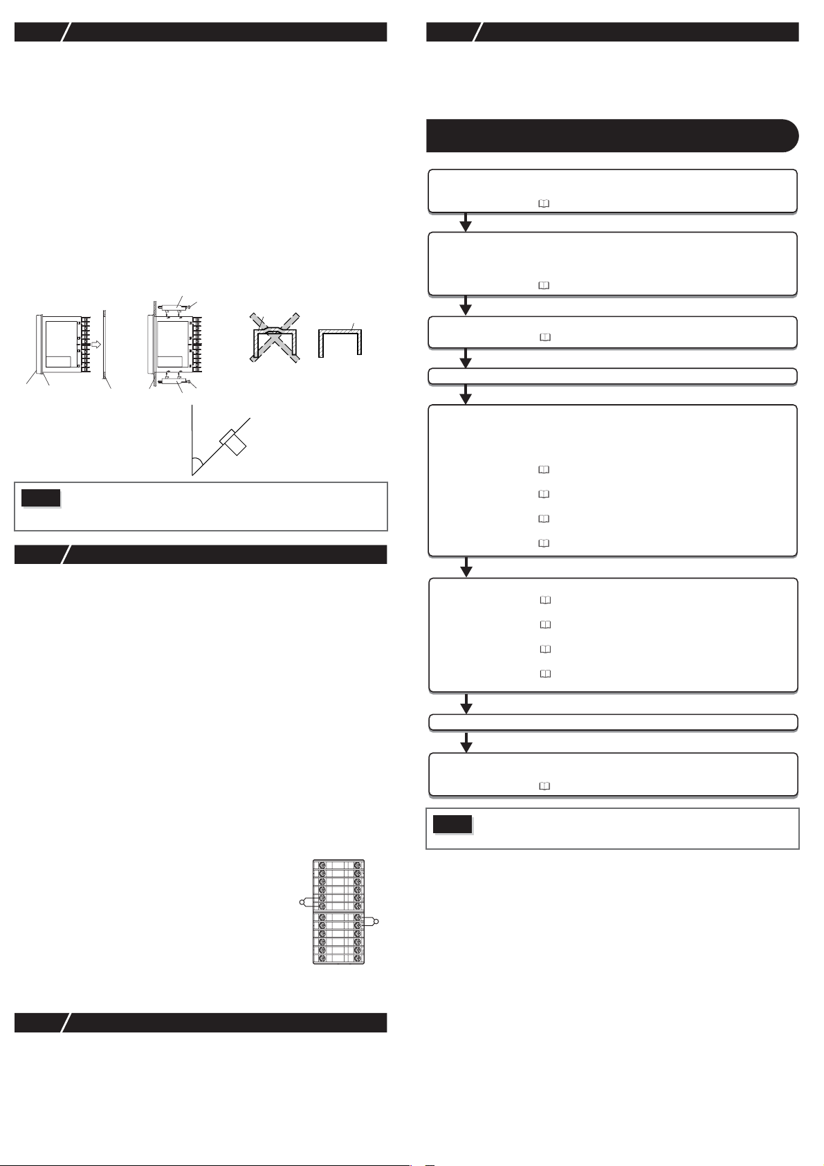
2-2
Please attach the PXG5/PXG9 with the included fixtures (2 pieces) to the top and bottom,
•
and tighten with a screwdriver.
The clamp torque is approximately 0.15 N/m (1.5 kg/cm)
•
It is designed such that overtightening will cause left/right cracking to the central area of
the Fixtures and hence reduce the torque.
Cracking to the central area will not cause any problems in terms of usability of the equipment.
(However, do exercise caution in not applying too much torque because the casing is
made of plastic.)
The front of this equipment is waterproof in compliance with NEMA-4X standards (IP66-
•
equivalent).
To effect waterproof, the included packing is shall be attached between the controller and
the panel according to the guidelines below. (Incorrect attachment may cause the equipment to lose its waterproof capabilities.)
(1) As shown in Fig. 1, insert to the panel after attaching the packing to the equipment
(2) As shown in Fig. 2, tighten the fixture screws so that no gaps can remain between the
If the panel does not have enough strength, gaps may develop between the packing and
•
the panel to lose waterproofing capabilities.
Fig. 1 Fig. 2
Front
Caution
2-3
•
For thermocouple input, use the designated compensation lead; for resistance bulb input,
use wires with small lead wire resistance and without any resistance difference among the
three wires.
•
To avoid noise conductor effects, input signal wires should be separated from electric
power lines or load lines.
•
Input signal wire and output signal wire should be separated each other. And both should be shield
wire.
•
If there is a lot of noise from the power source, adding an insulation transducer and using a
noise filter is recommended.
(Example: ZMB22R5-11, noise filter Maker: TDK)
Always attach a noise filter to a panel that is grounded securely, and keep the wiring
between the noise filter output side and the measuring equipment power terminal wiring
to a minimum length.
Please do not attach fuses and switches, etc. to the noise filter output wiring, otherwise the
filter’s effectiveness will be decreased.
•
Twisting the power wires is effective when connecting the wires. (The shorter the pitch of
the twist, the more effective the connection is against noise.)
•
If there is a function of heater current detection, heater wires and power wires should be
connected with same power line.
•
Operation preparation time is required for the contact output when power is turned on. If
using it as a signal to an external interlock circuit, please couple it with a delayed relay.
•
Concerning the output relay, connecting the maximum rated load will shorten the product’s life; so please attach an auxiliary relay. If the output operation frequency is high,
selecting a SSR/SSC drive output type is recommended.
•
When inductive loads such as magnetic opening/closing equipment, etc. as relay output equipment are connected, use of
“Z-trap,” manufactured by Fuji Electric Device Technology Co.,
Ltd., is recommended in order to protect the contacts against
opening/closing surges and to ensure long-term use.
Cautions when Attaching to the Panels
case.
equipment face, the packing and the panels. Once finished, confirm that there are no
changes in shape such as displaced or improperly-fitted packing, etc. as shown in
Fig. 3.
Unit
Packing
Standard: vertical attachment
(horizontal position attachment)
If attached at an angle, the maximum
gradient is a 30° downslope.
Panel
Panel
•
In order to aid heat dissipation, do not block the sides of the equipment.
•
Do not block the air vents on the upper part of the terminal.
•
For the PXG9, please attach the fixtures to the attachment holes in the
center of the main unit.
Mounting fixture
Screw
Screw
Mounting fixture
α = 0 to 30°
Packing
Case
(Bad)
Fig. 3
Packing
Case
(Good)
Cautions for Wiring
[Proportionate cycles] Relay output: 30 seconds or more, SSR/SSC drive output: 1
Model names : ENC241D-07A
Attachment position : Please connect between the relay
(For 100V power voltage)
ENC471D-07A
(For 200V power voltage)
control output contacts.
(Refer to Fig. 4.)
second or more
(Example)
1
25
2
26
27
3
28
4
29
5
30
6
7
31
8
32
9
33
10
34
11
35
12
Fig.4 Attachment posi-
36
tion of Z-Trap
2-5
Please do not wipe the equipment with organic solvents such as alcohol or benzene, etc.
•
If wiping is necessary, use a neutral cleaning agent.
Do not use mobile phones near this equipment (within 50 cm). Otherwise a malfunction
•
may result.
Trouble may occur if the equipment is used near a radio, TV, or wireless device.
•
Others
For Proper Usage
Confirmation of model code
1 Installation and Mounting
2
Wiring Connection
Turn Power On
3 Display and Operations
4 Parameter List
5 Functions of the Temperature Controller
6 Advanced Usage Setting of input sensor and input range
Operation
7 Error Indications
Caution
Wait 30 minutes for the controller to stabilized thermally. Operations such as
measurements should be taken after the equipment has been on for 30 minutes or more.
Please confirm that the model delivered matches your order.
"12 Model Specifications" (page 19)
External dimensions
• Panel cut dimensions
• Mounting the panel
"3 Installation and Mounting" (page 3)
Terminal connections diagram
"4 Wiring" (page 4)
Changing set value
"5 Display and Operations" (page 5)
Basic Operation Methods
"5 Display and Operations" (page 5)
Parameter List
"6 Parameter List" (page 6)
Input/Output/Control
"7 Functions" (page 10)
"8-1 Input Setting" (page 17)
Selecting control method
"8-3 Control Setting" (page 18)
Controlling through auto-tuning
"7-6 Auto-tuning" (page 11)
Automatic setting parameters
"7-3 Fuzzy PID Control", "7-4 Self-tuning Control" (page 10)
Display during equipment error
"9 Error Indications" (page 18)
2-4
•
The alarm function does not work properly when an error takes place unless the settings
are made correctly. Always verify its setting before operation.
•
If the input wiring breaks, the display will read “
turn the power OFF.
Key Operation Caution/Error Operation
UUUU
”. When replacing the sensor, always
– 2 –
Page 3
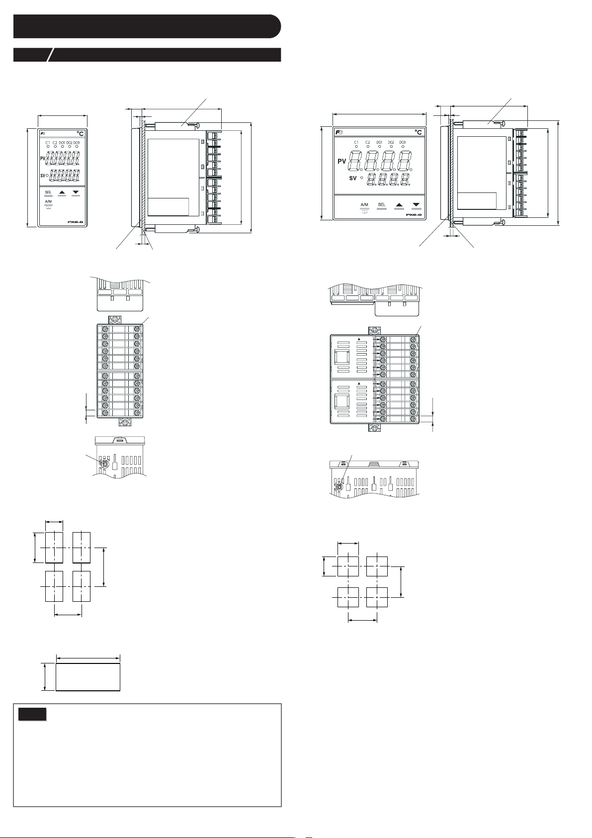
Installation and Mounting
3
3-1
PXG5
96
External/Panel Cut Dimensions
Mounting fixture
(fastening torque 0.15 N•m)
48
Waterproof packing
1-12
1
2
3
4
5
6
7
8
9
10
6.2
11
12
13-24
25-36
2
t
25
26
27
28
29
30
31
32
33
34
35
36
7810
Panel thickness
1 to 8 mm
panel
terminal
screw M3
91.5
115.5 MAX
PXG9
96
96
waterproof packing
1-12
13-2437-48 61-7249-60
terminal screw M3
TOP
1
2
3
4
5
6
TOP
7
8
9
10
11
12
25-36
mounting fixture
(fastening torque 0.15 N•m)
79.510
2
91.5
115.5 MAX
t
Panel thickness
1 to 8 mm
panel
25
26
27
28
29
30
31
32
33
34
6.2
35
36
PC loader interface
Installing multiple controllers
+0.6
0
45
+0.8
0
92
116 MIN.
50 MIN.
Installing multiple controllers horizontally
(In this installing, the waterproof of PXG is lost.)
+0.8
0
Caution
(48 × n–3)
+0.8
0
92
Panel cut dimensions should also meet the above dimensions after the panel
is coated.
Cautions when Close Fit Mounting:
When the power supply is AC 200V, keep the maximum ambient temperature
•
at 45°C. For vertical close-fit mounting, use a power source of AC 100V. (In
both cases, a fan is recommended as a measure against radiation.)
•
When there is an instrument larger than 70 mm or a wall to the right of
the controller, move it as least 30 mm away.
Cautions when wiring:
•
Start by wiring from the left-hand terminals (terminals 1 to 12).
•
Use a screw that is the right size on terminals and tighten them with a
torque of about 0.8 N/m.
•
Do not attach anything to unused terminals. (Do not use relay terminals.)
PC loader interface
Installing multiple controllers
+0.8
92
0
+0.8
0
92
116 MIN.
100 MIN.
– 3 –
Page 4
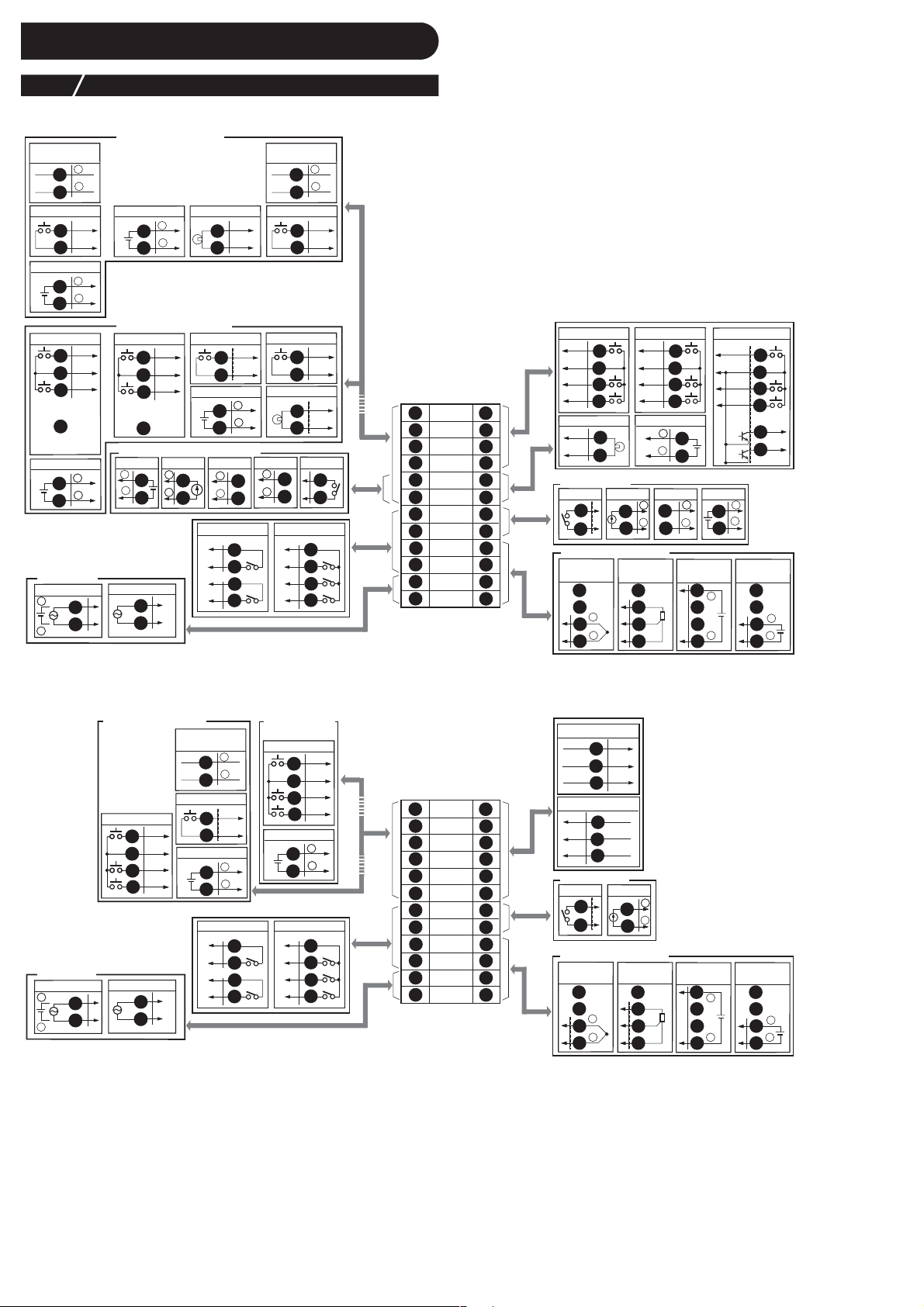
4
Wiring
4-1
●
Standard T ype
RS485
communicator
Digital input Digital inputRSV1 input
RSV1 input
Digital input
RSV1 input
Power supply
AD/DC 24V
++
–
Terminal Connection Diagram (100 to 240V AC, 24V AC/DC)
+
1
–
2
DI1
3
DI–COM
4
+
5
–
6
DI1
1
1
DI–COM
2
2
DI2
DI2
3
3
No
4
4
connection
++
5
–
6
AC100 to 240V
11
4
12
50/60Hz
50/60Hz
Communication function
included
XPS output
++
125
–
6
CT input
3
4
Digital input
DI1
1
DI–COM
2
RSV1 input
++
343
–
4
SSR drive
++
125
–
6
Digital output
DO1–COM
7
DO1
8
DO2–COM
9
DO2
10
+
3
–
4
No communication function
Digital input
DI1
1
1
DI–COM
2
2
DI2
DI2
3
3
No
4
4
connection
Control output 2/Re–transmission
Voltage output
+
5
–
6
(Note 3)
11
4
12
(Note 1)
RS485
communicator
1
2
3
4
Digital input
1
1
2
2
CT1 input
3
4
Relay output
Current output
++
125
–
6
DIgital output
DO–COM
DO1
DO2
DO3
+
–
DI1
DI–COM
DI1
DI–COM
5
6
7
8
9
10
Digital input
DI3
25
DIO–COM
26
DI4
27
DI5
1
2
3
4
5
6
7
8
9
10
11
12
25
26
27
28
29
30
31
32
33
34
35
36
28
CT2 input
29
30
Control output 1
Relay output
31
32
Measurement value input
Thermocouple
input
33
34
+
35
–
36
Digital input
DI3
DIO–COM
DI4
DI5
RSV2 input
Current output
++
31
–
32
Resistance
bulb input
33
A
34
B
35
B
36
25
26
27
28
++
29
–
30
SSR drive
31
32
Current/voltage
input
(Note 2)
Digital input/output
DIO–COM
Voltage output
++
31
3
–
4
32
33
+
34
35
–
36
DI3
25
26
DI4
27
DI5
28
29
30
+
–
Voltage (mV)
input
33
34
35
36
DO4
DO5
+
–
●
Motorized Valv e Type
+
–
DI1
DI–COM
+
–
7
8
9
10
No communication
function
Digital input
DI1
1
1
DI–COM
2
2
DI2
3
3
DI3
4
RSV1 input
++
5
–
6
DO–COM
7
DO1
8
DO2
9
DO3
10
Ω
resistor) between the terminals number 33 and 36.
Communication function
included
Digital input
1
3
2
4
3
5
6
Power supply
AD/DC 24V
++
–
50/60Hz
Note 1: Check the power supply voltage before making the connections.
Note 2: When inputting current, connect the additional I/V unit (250
Note 3: Transmitter power output is an option only for PXG9.
11
4
12
AC100 to 240V
50/60Hz
DI1
DI1
DI–COM
DI2
DI3
11
4
12
(Note 1)
RS485
communicator
1
2
Digital input
3
4
RSV1 input
5
6
Digital output Digital output
DO1–COM
DO1
DO2–COM
DO2
Valve control output
CLOSE
25
COM
26
OPEN
27
1
2
3
4
5
6
7
8
9
10
11
12
25
26
27
28
29
30
31
32
33
34
35
36
PFB input
I +
28
I 0
29
I –
30
Control output 1
AUX DO
Measurement value input
Thermocouple
input
XPS output
31
32
33
34
+
35
–
36
++
31
–
32
Resistance
bulb input
33
A
34
B
35
B
36
(Note 3)
Current/voltage
input
(Note 2)
Voltage (mV)
33
34
35
36
input
33
+
34
+
35
––
36
– 4 –
Page 5
Display and Operations
fixed at 0
8bit : PV input underflow
9bit : PV input overflow
10bit: underrange
11bit: overrange
12bit: RSV underrange
13bit: RSV overrange
14bit: range setting error
15bit: EEPROM error
0bit: PFB input underflow
1bit: PFB input overflow
5
5-1
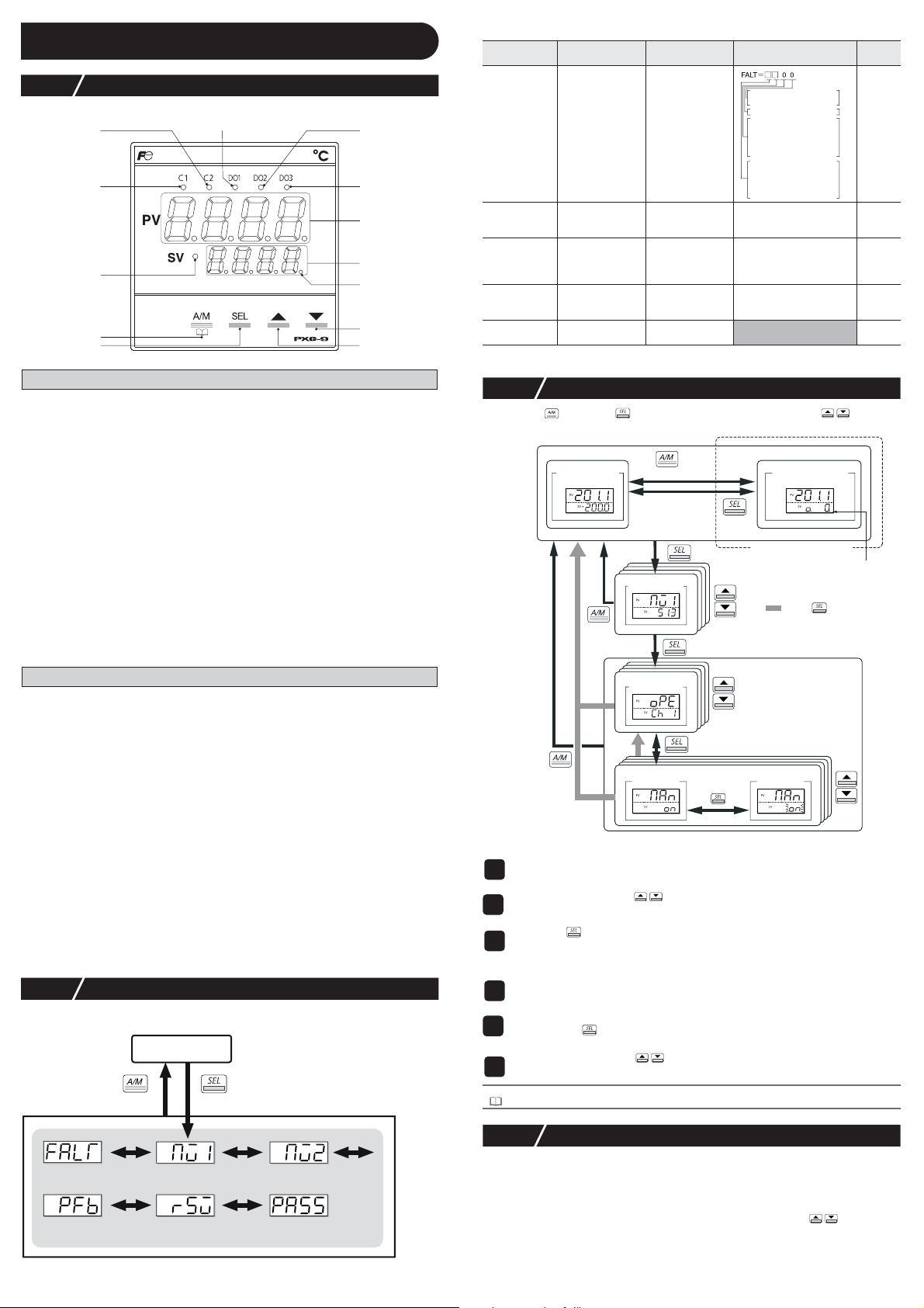
Part names and functions
Parameter
display symbol
"
"
(FALT)
FALT
Parameter name Function Setting range
Error source
display
Displays the
source of an error
Remarks
C2 Lamp
C1 Lamp
SV Lamp
USER Key
SEL Key
DO1 Lamp
DO2 Lamp
DO3 Lamp
PV Display
SV Display
MAN/AT/SELF
Lamp
▼ Key
▲ Key
Operation Parts
USER Key
Pressing this key in monitoring mode display or setup mode display returns you to the PV/SV display.
Pressing this key on the PV/SV display allows you to set the function for "
("
SYS Ch 7
"). (The factory set function for this key is switching between auto and manual.)
SEL Key
Switches the PV/SV display to the monitoring mode display or setup mode display.
Switches to setup mode when parameter display , and this k ey functions as the select key when changing
parameters.
Holding this key down in channel display or parameter display returns you to the PV/SV display.
Pressing this key at PV/SV display in manual mode, manual output value is shown
in the lower display.
▲ Key
Pressing once will increase the setting value by one. Holding down the button will continue to
increase the value.
It changes SV on the PV/SV display.
It is also used to move between items in channel screen display and parameter screen display.
▼ Key
Pressing once will decrease the setting value by one. Holding down the button will continue to
decrease the value. It changes SV on the PV/SV display.
It is also used to move between items in channel screen display and parameter screen display.
UkEY
" under the system menu
Display
C1/C2 Lamp
Displays the condition of the control output. Lights ON at 100% output and goes out at 0% output. For values between 0% and 100%, the output is indicated by the length of time the lamp
flickers.When acting as a valve control, the C1 lamp will light with OPEN output, and the C2
lamp will flickers with CLOSE output.
DO1/2/3 Lamp
Lights ON when there is digital output is on state (DO1, DO2, DO3). The lamp flickers when
delay behavior is on.
PV Display
Displays the measurement value (PV). Displays the name of the parameter when setting
parameters.
SV Display
Displays the setting value (SV). Also can display the output value during manual mode. Displays the parameter setting value when setting parameters. Displays "
operation, and "
SV Lamp
Lights when displaying the setting value (SV). Goes out when displaying the manual output
value.
The lamp flickers while performing ramp soak or lamp SV operations.
MAN/AT/SELF Lamp
Normally lights up during manual mode and blinks during auto-tuning or self-tuning.
SoFT" and set value alternately during soft start.
rEM" during remote SV
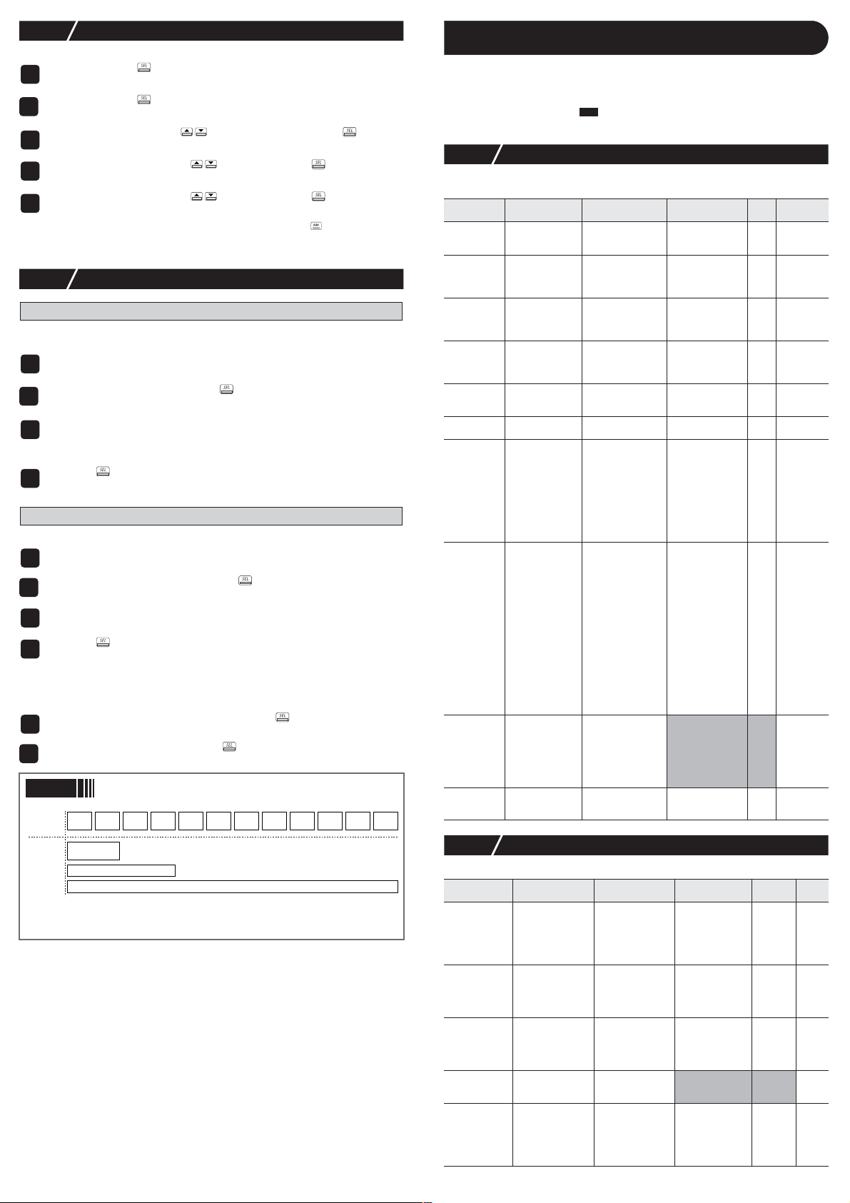
5-2 Monitor Display and Status Display
In monitor mode, the PV display shows item names, while the SV display shows the
input/output values.
operation mode
monitor mode
hold down
Mv1
"
" (Mv1) MV1 Displays the output
Mv2
" (Mv2) MV2 Displays the output
"
PFb
" (PFb) Displays the PFB
"
" (rSv) RSV input value
rSv
"
For more details on (Note) in the Remarks column, see “6 Parameter List” (page 6).
input value
display
value of the control
output (OUT1)
value of the control
output (OUT2)
(during dual control)
Displays the input
value of the
position feedback
Displays the input
value of the RSV
-3.0 to 103.0%
-3.0 to 103.0% (Note4)
-3.0 to 103.0% (Note8)
-5 to 105% FS (initial value) (Note1)
5-3 Basic Operations
Pressing the key or the key switches between modes. Pressing in monitor
mode or setup mode allows you to choose menu items.
hold down
observation
parameter
menu
(change
mode)
hold down
hold down
hold down
(change
display only)
only during manual mode
monitor mode
channel display
manual mode
manual output
(PV/MV display)
manual lamp ON
: Press several times
setup mode
parameter display
parameter
setting
operation mode
initial display
(PV/SV display)
value display
channel menu
● Changing SV (set values)
Change the display to PV/SV display (shown when you turn on the power and
1
the SV lamp is lit).
Change the SV with the keys.
2
Press the key to save the values.
3
(The value will be automatically saved after 3 seconds even if a key is not pressed.)
● Changing MV (control output values)
Switch to manual mode.
1
Change the display to PV/MV display (MAN/AT/SELF lamp is lit).
2
(Pressing the key in manual mode toggles between PV/SV display and PV/MV
display.)
Change the MV with the keys.
3
(Changes are reflected to the MV as it is changed.)
Refer to
See “7-9 Manual Output” (page 12) for more about changing to manual mode.
display
PFB input value
display (%)
For more details on “
MV1 (%)Error source
RSV terminal
input value display
PASS” (PASS), see “5-6 Key Lock and Password” (page 6).
MV2 (%)
Password entry
5-4 Operations
For the following modes, the PV display will show the PV input value.
● Operation Mode
SV display shows the SV setting value.
● Manual Mode
An LED light decimal point lights ON in the lowest digit place in the SV display. An “o”
appears in the highest decimal place during MV display. Pressing the keys sets the
MV (%).
– 5 –
Page 6
5-5
…
The following explains how to set the parameters.
1
2
3
4
5
●
No matter where you are in monitor or setup mode, pressing the key returns you to
operation mode. When setting the parameters in manual mode, pressing the key holds
manual mode and returns you to operation mode.
5-6
Setting Parameters
Press and hold the key in operation mode, or manual mode.
This switches you to the monitor mode Mv1.
Press and hold the key in monitor mode
This switches you to the channel menu of setup mode.
Choose the channel with the keys, then press and hold the key.
This switches you to the parameter menu.
Choose the parameter with the keys, then press the key.
The set value flickers.
Choose the parameter with the keys, then press the key.
The set value is fixed.
Key Lock and Password
Setting Key Lock
When key lock is activated, parameters cannot be changed but can displayed. Use the following steps to set key lock.
Display the operation menu ("oPE Ch 1").
1
Display key lock ("LoC") and press the key.
2
Set the value.
3
0 : No lock (all parameters can be changed. Initial value.)
1 : All lock (no parameters can be changed.)
2 : All lock without SV (only the SV can be changed.)
Press the key to set the value.
4
Saving and entering a password
Use the following steps to save a password.
Display the password menu ("PAS Ch11").
1
Display password 1 ("PAS1") and press the key.
2
Set the password.
3
You can enter the hexadecimal value 0000 through FFFF.
Press the key to set the value.
4
"
PAS2" and "PAS3" can be saved in the same way.
●
The authority of the passwords grows from "
ity, the greater number of channels for display and settings.
Use the following steps to enter a password.
In monitoring mode, display ("PASS") and press the key.
1
Enter a saved password and press the key.
2
You will be able to operate the equipment depending on the authority of your password.
Point
Each parameter channel and the authority of passwords 1 to 3
oPE ch
Pid ch PLT ch PrG ch Mon ch SET ch SyS ch ALM ch CoM ch PFb ch PAS ch dSP ch
PAS1
" to "
PAS2
" to "
PAS3
". The higher the author-
Parameter List
6
Remarks
(Note1)
Displays End
(when ending)
or GS (during
guaranty soak).
(Note20)
d
(Note3)
The following explains each channel parameter.
The list also shows the operational range of set values for parameters that are limited.
•
When the PV input lower limit (Pvb), PV input upper limit (PvF), or decimal place position
(Pvd) is changed, reconfigure all the initial parameter setting values.
•
When the parameter that has
once, and then re-start the controller.
6-1
The following is a menu to operate the controller. Switchover between auto and manual control
output, switchover between RUN and standby, and other such functions.
Parameter
display symbol
man" (MAn) Switchover
"
STbY" (STby) Switchover
"
rEm" (rEM) Switchover
"
"PrG" (PrG) Ramp soak
"At" (AT) Auto-tuning run
LA[h"
"
(LACh)
Svn" (Svn) Currently
"
"PLn1" (PLn1) Currently
AL1
"
" (AL1)
AL1L
"
"
AL1h
…
"
AL5
" (AL5)
"
AL5L
AL5h
"
LoC
"
" (LoC) Key lock Sets the key lock to
Operation (Ch1)
Parameter name Function Setting range
between auto and
manual mode
between RUN
and standby
between local
and remote SV
operation
control command
command
DO output latch
release command
selected SV No.
selected PID No.
AL1 set value
" (AL1L)
AL1L set value
" (AL1h)
AL1h set value
AL5 set value
" (AL5L)
AL5L set value
" (AL5h)
AL5h set value
RST
on its Remarks column is changed, turn off the power
Initial
value
oFF
oFF
LoCL
oFF
oFF
oFF (Note2)
Sv0
Pid0
" P
10°C
0
Switchover between
auto and manual
modes
Switchover the
operation mode
between RUN and
standby
Switchover between
local and remote SV
operation
Changes ramp soak
run states
Runs auto-tuning. oFF (stop/finish)
Cancels the DO
latch state
Choose the SV No.
used for control
Choose the PID
group No. used for
control
Set the alarm value.
prevent wrong
operation
oFF (auto) / on
(manual)
oFF (RUN) / on
(standby)
LoCL (local) / rEM
(remote)
oFF (stop)
rUn (run)
hLd (hold)
on (normal type)
Lo (low PV type)
oFF / rST
(latch resets)
Sv0
Sv1
Sv2
Sv3
Sv4
Sv5
Sv6
Sv7
di (chooses SV
according to di)
Pid 0 (PID ch)
id
P
1
(PID group No. 1)
id
P
2
(PID group No. 2)
id
P
3
(PID group No. 3)
id
P
4
(PID group No. 4)
id
P
5
(PID group No. 5)
id
P
6
(PID group No. 6)
id
P
7
(PID group No. 7)
di (chooses PID
group according to di)
0 to 100% FS
(absolute value
alarm)
-100 to 100% FS
(deviation alarm)
0 (no lock)
1 (all lock)
2
(All but SV locked)
Password
level
Note: When “
PAS1 permissions
<"PASS" = "PAS1">
PAS2 permissions <"PASS" = "PAS2">
PAS3 permissions <"PASS" = "PAS3">
FEFE” (FEFE) is entered as “PASS” (PASS), all of the channels “OPE ch” to
“DSP ch” can be displayed and set. This “super password” function is useful when
you forget the set passwords.
6-2
Sets parameters for controls such as PID.
Parameter
display symbol
" (P) Proportional band Sets the
" (i) Integration time
i
"
"
" (d) Differential time
hyS
"
" (hyS) ON/OFF control
"
[oL
" (CoL) Cooling
PID (Ch2)
Parameter name Function Setting range
hysteresis
proportional band
coefficient
– 6 –
proportional band
of the PID
parameter. Setting
"0.0" will turn it to
an ON/OFF control.
Sets the integration
time of the PID
parameter. Setting
"0" will turn off
integration.
Sets the differential
time of the PID
parameter. Setting
"0.0" will turn off
derivation.
Sets the hysteresis
width for the ON/
OFF control.
Sets the cooling
proportional band
coefficient. Setting
"0.0" will turn the
cooling into an ON/
OFF control.
Initial
0.0 to 999.9% 5.0%
0 to 3200 sec 240 sec
0.0 to 999.9 sec 60.0 sec
0 to 50% FS 1°C
0.0 to 100.0 1.0
value
Remarks
(Note4)
Page 7

Parameter
display symbol
db" (db) Dead band Shifts the cooling
"
"bAL" (bAL) Output
Ar" (Ar) Anti-reset
"
rEv" (rEv) Sets normal/
"
SvL" (SvL) SV limit
"
"Svh" (Svh) SV limit
"t[1" (TC1) OUT1 proportion
"t[2" (TC2) OUT2 proportion
"Plc1" (PLC1)
Ph[1" (PhC1)
"
PL[2" (PLC2)
"
"Ph[2" (PhC2)
"P[UT" (PCUT) Selects the type of
6-3
Parameter name Function Setting range
-50 to 50% 0%
-100 to 100% 0/50
0 to 100% FS 100%FS
rv-- (heat (reverse)
no-- (heat (normal)
rvno (heat (reverse)
/cool (normal))
norv (heat (normal)
/cool (reverse))
rvrv (heat (reverse)
/cool (reverse))
nono (heat (normal)
/cool (normal))
0 to 100% FS 0% FS
0 to 100% FS 100% FS
1 to 150 sec 30:
1 to 150 sec 30:
-3.0 to 103.0% -3.0%
-3.0 to 103.0% 103.0%
-3.0 to 103.0% -3.0%
-3.0 to 103.0% 103.0%
0 to 15 0
convergence value
windup
reverse operations
(lower limit)
(upper limit)
cycle
cycle
OUT1 lower limit
OUT1 upper limit
OUT2 lower limit
OUT2 upper limit
output limiter
proportional band
from the set value
Offset value which
is added to the MV
output value
Sets the range of
integration control
Sets the control
action
Sets the lower limit
of SV
Sets the upper
limit of SV
Sets the proportion
cycle of the control
output (OUT1)
(contacts, SSR drive)
Sets the proportion
cycle of the control
output (OUT2)
(contacts, SSR drive)
Sets the lower limit
of the control output
(OUT1)
Sets the upper limit
of the control output
(OUT1)
Sets the lower limit
of the control output
(OUT2)
Sets the upper limit
of the control output
(OUT2)
Sets the type of
output limiter
PID Palette (Ch3)
/cool (none))
/cool (none))
Saves the palette values of PV and PID. Up to seven sets can be saved.
Parameter
display symbol
"Sv1" (Sv1) SV 1 Sets the SV set
"P1" (P1) Proportional band 1 Sets the
i1" (i1) Integration time 1 Sets the
"
d1" (d1) Differential time 1 Sets the
"
"hyS1" (hyS1) ON/OFF control
"
[oL1" (CoL1) Cooling proportional
"db1" (db1) Dead band 1 Sets the dead
"bAL1" (bAL1)
Ar1" (Ar1) Anti-reset windup 1 Sets the anti-reset
"
"rEv1" (rEv1) Sets normal/
"Sv7" (Sv7) SV 7 Sets the SV set
"P7" (P7)
i7" (i7) Integration time 7 Sets the
"
d7" (d7) Differential time 7 Sets the
"
"hyS7" (hyS7) ON/OFF control
"
[oL7" (CoL7)
Parameter name Function Setting range
value
proportional band
integration time
differential time.
Sets the hysteresis
when using the
ON/OFF control.
Sets the cooling
proportional band
band
Offset value which
is added to the
control output
windup
Sets the control
action
…
value
Sets the
proportional band
integration time
differential time.
Sets the hysteresis
when using the
ON/OFF control.
Sets the cooling
proportional band
…
hysteresis 1
band 1
Output convergence
value 1
reverse 1
…
Proportional band 7
hysteresis 7
Cooling proportional
band 7
SV limit (lower)
(SVL) to
SV limit (upper)
(SVH) %FS
0.0 to 999.9% 5.0%
0 to 3200 sec 240 sec
0.0 to 999.9 sec
0 to 50% FS 1 °C
0.0 to 100.0 1.0
-50.0 to 50.0% 0%
-100.0 to 100.0% 0/50
0 to 100% FS
rv-- (heat (reverse)/
cool (none))
no-- (heat (normal)/
cool (none))
rvno (heat (reverse)/
cool (normal))
norv (heat (normal)/
cool (reverse))
rvrv (heat (reverse)/
cool (reverse))
nono (heat (normal)/
cool (normal))
…
SV limit (lower)
(SVL) to
SV limit (upper)
(SVH) %FS
0.0 to 999.9% 5.0%
0 to 3200 sec 240 sec
0.0 to 999.9 sec
0 to 50% FS 1 °C
0.0 to 100.0 1.0
Initial
value
(single/
dual)
rv--/rvno
(single/
dual)
Contact
2: SSR
drive
Contact
2: SSR
drive
Initial
value.
0%FS
60.0 sec
(single/
dual)
100%FS
rv--/rvno
(single/
dual)
…
0%FS
60.0 sec
Remarks
(Note4)
RST
(Note5)
(Note5)
(Note7)
(Note4)
(Note4)
(Note4)
Remarks
(Note5)
(Note4)
(Note4)
(Note6)
RST
…
(Note5)
(Note4)
Parameter
display symbol
"db7" (db7) Dead band 7 Sets the dead
"bAL7" (bAL7)
Ar7" (Ar7)
"
"rEv7" (rEv7) Sets normal/reverse 7Sets the control
"SvMX" (SvMX) Sets the Max SV
"
PL1m" (PL1M) Set the Max PID
6-4
Create a pattern of temperatures using ramp soak combinations . You can create a temperature
pattern with up to 16 steps.
Parameter
display symbol
Ptn
" (PTn) Ramp soak
" (TiMU) Ramp soak time
TiMU
Sv-1
"
"
(Sv-1)
" (TM1r) Ramp soak 1 seg
tm1r
"
tm1S
" (TM1S) Ramp soak 1 seg
Sv16
"
(Sv16)
t16r"
"
(T16r")
"t16S" (T16S) Ramp soak 16
"mod" (Mod)
Gsok" (Gsok) Guaranty soak
"
GS-L"(GS-L) Guaranty soak
"
"
GS-h"(GS-h) Guaranty soak
"PvST"( PvST) PV start Sets whether or
" ConT "(ConT) Restore mode Sets how to
" (PTnM) Sets the Max
PTnM
" PMin "(PMin) Sets the Min
Parameter name Function Setting range
Output convergence
value 7
Anti-reset windup 7
selection number
selection number
band
Offset value which
is added to the
control output
Sets the anti-reset
windup
action
Choosing SV with
the user key sets it
to the maximum
possible number.
Choosing PID with
the user key sets it
to the maximum
possible number.
Ramp soak (Ch4)
Parameter name Function Setting range
…
"
operation pattern
(Step No.)
units
Ramp soak 1 seg/
SV
ramp time
soak time
Ramp soak 16 seg/
SV
Ramp soak 16
seg ramp time
seg soak time
Ramp soak mode
ON/OFF
band (lower)
band (upper)
pattern selection
pattern selection
…
Sets which
steps to use in
the ramp soak
operation
pattern
Sets the units
of the ramp
soak time
Sets the SV
Sets the ramp
time
Sets the soak
time
…
Sets the SV
Sets the ramp
time
Sets the soak
time
Sets the
program
operation
method
Sets the
guaranty soak
ON or OFF
Sets the lower
limit of guaranty
soak
Sets the upper
limit of guaranty
soak
not to start
ramp soak with
PV.
restart when
the controller is
restored after a
power loss.
Choosing
pattern with the
user key sets it
to the
maximum
possible
number.
Choosing
pattern with the
user key sets it
to the minimum
possible
number.
-50.0 to 50.0% 0%
-100.0 to 100.0% 0/50
0 to 100% FS
rv-- (heat (reverse)
/cool (none))
no--(heat (normal)
/cool (none))
rvno (heat (reverse)
/cool (normal))
norv (heat (normal)
/cool (reverse))
rvrv (heat (rev erse)
/cool (reverse))
nono (heat (normal)
/cool (normal))
Sv0
Sv1
Sv2
Sv3
Sv4
Sv5
Sv6
Sv7
di
Pid0
Pid1
Pid2
Pid3
Pid4
Pid5
Pid6
Pid7
di
0 (uses steps 1 to 4)
1 (uses steps 5 to 8)
2 (uses steps 1 to 8)
3 (uses steps 9 to 12)
4 (uses steps 13 to 16)
5 (uses steps 9 to 16)
6 (uses steps 1 to 16)
di (according to di)
hh.MM (hour:min)
MM.SS (min:sec)
0 to 100% FS 0%FS
00.00 to 99.59 (hour:min/
min:sec)
00.00 to 99.59 (hour:min/
min:sec)
0 to 100% FS 0%FS
00.00 to 99.59 (hour:min/
min:sec)
00.00 to 99.59 (hour:min/
min:sec)
0 to 15 0
oFF (guaranty soak off)
on (guaranty soak on)
0 to 50% FS 5°C
0 to 50% FS 5°C
oFF (PV start OFF)
on (PV start ON)
rES (Reset)
Con (Continue)
ini (Restart)
0 to 6,di 6
0 to 6, di 0
…
– 7 –
Initial
value.
(single/
dual)
100% FS
rv--/rvno
(single/
dual)
Sv7
"
id
P
7
Initial
value
6
hh.MM
00:00
(hour:min)
00:00
(hour:min)
…
00:00
(hour:min)
00:00
(hour:min)
oFF
oFF
rES
"
Remarks
(Note4)
(Note6)
RST
"
Remarks
(Note 21)
…
RST
(Note 20)
"
Page 8

6-5
You can check the ramp soak progress, control output, heater current, remaining time, and
other status functions.
Parameter
display symbol
StAt
" (Mv1) MV1 Displays the output
Mv1
"
Mv2
"
" (Mv2) MV2 Displays the output
" (PFb) Displays the PFB
PFb
"
rSv
"
" (rSv) RSV input value
[t1
"
"
LC1
"
tm1
"
"
tm5
"
"
FALT
"
" PLno "( PLno) Current palette No. Displays the PID
" PTno "( PTno) Current pattern
6-6
Monitor (Ch5)
Parameter name Function Setting range
" (STAT) Ramp soak
progress
input value
display
…
(FALT)
Heater current 1
Leak current value
1
Remaining time on
timer 1
Remaining time on
timer 5
Error source
display
"
No.
(CT1)
" (LC1)
(TM1)
(TM5)
"
Setup (Ch6)
Remarks
Displays the
progress of the
ramp soak
value of the control
output (OUT1)
value of the control
output
(OUT2)(during dual
control)
Displays the input
value of the
position feedback
Displays the input
value of the RSV
Displays the current
through the CT
Displays the leak
current value of CT.
Displays the remaining
time on timer 1
…
…
Displays the remaining
time on timer 5
Displays the
source of an error
palette No.
currently selected.
Displays the
"
"
pattern No. of the
ramp soak
currently selected.
oFF (ramp soak stopped)
1-rP (ramp in step 1)
1-Sk (soak in step 1)
16rP (ramp in step 16)
16Sk (soak in step 16)
End (ramp soak finished)
-3.0 to 103.0%
-3.0 to 103.0% (Note4)
-3.0 to 103.0% (Note8)
-5 to 105% FS (Note1)
0, 0.4 to 50.0A
0, 0.4 to 50.0A
0 to 9999 sec/ 0 to 9999min (Note3)
0 to 9999 sec/ 0 to 9999min
0bit: PFB input underflow
1bit: PFB input overflow
fixed at 0
8bit : PV input underflow
9bit : PV input overflow
10bit: underrange
11bit: overrange
12bit: RSV underrange
13bit: RSV overrange
14bit: range setting error
15bit: EEPROM error
0 to 7
0 to 6
"
"
"
…
(Note10)
(Note13)
(Note 10)
(Note 13)
…
"
"
"
Sets up the input range, output range, and other items for the equipment.
Parameter
display symbol
" (PvT) PV input type Sets the type
PvT
Pvb
" (Pvb) PV input lower
"
PvF
"
" (PvF) PVinput upper
" (Pvd) Decimal point
Pvd
"
" (PvoF) PV input shift
PvoF
"
"
tF
" (TF) PV input filter
rEm0
"
" (rEM0) RSV Zero
rEmS
" (rEMS) RSV Span
" (rEMr) RSV input
rEmr
rtF
" (rTF) RSV input
Parameter name Function Setting range
of input sensor
Sets the lower
limit
limit
position
adjustment
adjustment
range
filter
limit of PV input
Sets the upper
limit of PV input
Sets the number
of decimal point
positions for the
PV/SV
Sets the amount
of shift for PV
input
Sets the time
constant for the
PV input filter
Adjusts the zero
RSV input
Adjusts the
span RSV input
Sets the range
for RSV input
Sets the time
constant for the
RSV input filter
0 (no function)
1 (PT 100
Ω
2 (J)
3 (K)
4 (R)
5 (B)
6 (S)
7 (T)
8 (E)
9 (no function)
10(no function)
11 (no function)
12 (N)
13 (PL14 (no function)
15 (0 to 5V / 0 to 20mA)
16 (1 to 5V / 4 to 20mA)
17 (0 to 10V)
18 (2 to 10V)
19 (0 to 100mV)
)
)
2
-1999 to 9999 0
-1999 to 9999 400
0 (No digit after decimal point)
1 (1 digit after decimal point)
2 (2 digit after decimal point)
-10 to 10% FS
0.0 to 120.0 sec 5.0 sec
-50 to 50% FS
-50 to 50% FS
0-5 (0 to 5V)
1-5 (1 to 5V)
0.0 to 120.0 sec 0.0 sec
Initial
Remarks
value
3 (K)
RST
°
C
RST
°
C
RST
0
RST
0%FS
0%FS (Note1)
0%FS (Note1)
1-5
(Note1)
(Note1)
Parameter
display symbol
" (C1r) OUT1 range Sets the range
[1r
[2r
" (C2r) OUT2 range
FLo1
" (FLo1) Output 1 set
Flo2
"
" (FLo2) Output 2 set
" (SFo1) Soft Start
SFo1
"
SFtm
" (SFTM) Soft Start set
Sbo1
" (Sbo1) OUT1 output
Sbo2
"
(
"
Sbo2)
Sbmd
" (SbMd) Standby mode
" (AoT) Types of AO
Aot
" (AoL) AO lower limit
AoL
Aoh
" (Aoh) AO upper limit
6-7
"
"
"
"
System (Ch7)
Parameter name
value during
FALT
value during
FALT
output 1 set
value
time
set value
during standby
OUT2 output
"
set value
during standby
setting
output
scaling
scaling
Function
of the control
output (OUT1)
Sets the range
of the control
output (OUT2)
(Also sets for the
re-transmission
output)
Sets the output
value for the
control output
(OUT1) during
FALT
Sets the output
value for the
control output
(OUT2) during
FALT
Sets the output
value for the
control output
(OUT1) during
soft start
Sets the time from
startup to the finish
of soft start
Sets the output
value for the
control output
(OUT1) during
standby
Sets the output
value for the
control output
(OUT2) during
standby
Sets the alarm
output, retransmission
output, and
PV/SV display
during standby
Displays the
types of retransmission
output
Sets the lower
limit of AO
Sets the upper
limit of AO
Setting range
0-5 (0 to 5V)
1-5 (1 to 5V)
0-10 (0 to 10V)
2-10 (2 to 10V)
0-20 (0 to 20mA)
4-20 (4 to 20mA)
0-5 (0 to 5V)
1-5 (1 to 5V)
0-10 (0 to 10V)
2-10 (2 to 10V)
0-20 (0 to 20mA)
4-20 (4 to 20mA)
-3.0 to 103.0% -3.0%
-3.0 to 103.0%
-3.0 to 103.0%
00:00 to 99:59 (hour:min) 0.00
-3.0 to 103.0% -3.0%
-3.0 to 103.0% -3.0% (Note4)
ALM
display/
output
0 OFF ON ON
1ON ON ON
2 OFF OFF ON
3ON OFF ON
4 OFF ON OFF
5ON ON OFF
6 OFF OFF OFF
7ON OFF OFF
PV
SV
MV
DV
-100 to 100% 0%
-100 to 100% 100%
Assigns the functions of the DI/DO, LED lamp, and other controls.
Parameter
display symbol
UkEy
" (UkEy) Assigns the
Parameter
name
USER key
Function Setting range
Sets the
function of the
[USER] key
"
0 (no function)
1 (Switchover between STBY ON/OFF)
2 (Switch
over
between Auto/Manual)
3 (Switchover between Local/Remote)
4 (no function)
5 (Starts AT (standard))
6 (Starts AT (low PV))
7 (Ramp SV on/off)
8 (Ramp SV HOLD)
9 (Ramp soak OFF)
10 (Ramp soak RUN/HOLD)
11 (no function)
12 (Latch release (all))
13 (Latch release (DO1))
14 (Latch release (DO2))
15 (Latch release (DO3))
16 (Latch release (DO4))
17 (Latch release (DO5))
18 (Start timer (DO1))
19 (Start timer (DO2))
20 (Start timer (DO3))
21 (Start timer (DO4))
22 (Start timer (DO5))
23 (SV No. + 1 (send))
24 (PID No. + 1 (send))
25 (no function)
26 (Ra
+ 1 (send))
27 (SV No. + 1,
PID No. + 1 (send))
mp soak
pattern No.
Ao
outpu
t
PV/SV
displa
y
Initial
Remarks
value
(Note9)
0-10
(voltage
(Note14)
) 4-20
(current)
(Note12)
0-10
(voltage
(Note14)
4-20
)
(Note18)
(current)
-3.0% (Note4)
103.0%
Be
(hour:
sure to
min)
set
0.00
during
dual
control.
(Note15)
0
RST
(Note12)
Pv
(Note12)
(Note12)
Initial
Remarks
value
2
RST
– 8 –
Page 9

Parameter
display symbol
di1
" (di1) DI-1 function
di5" (di5) DI-5 function
do1t" (do1T) Sets the DO1
"
doP1" (doP1) Sets DO1
"
"do5t" (do5T) Sets the DO5
doP5" (doP5) Sets DO5
"
rmP" (rMP) ramp SV
"
rmPL" (rMPL) Ramp SV-
"
"rmPh" (rMPH) Ramp SV-
"rmPU" (rMPU) Ramp SV-
"Svt" (SvT) Ramp SV - SV
[trL" (CTrL) Control
"
…
…
Parameter
name
selection
…
selection
output event
type
option function
…
output event
type
option function
ON/OFF
Decline
Incline
slope units of
time
display mode
selection
methods
Function Setting range
Sets the
function of
DI-1
Sets the
function of
DI-5
Sets the
function of
DO1
Assigns the
four types of
option
functions in
bit units
Sets the
function of
DO5
Assigns the
four types of
option
functions in
bit units
Sets the
ramp SV
ON/OFF
Sets the slope
for a falling SV
during ramp
SV operations
Sets the slope
for a rising SV
during ramp
SV operations
Sets the unit
of time for the
slope during
ramp SV
operations
Displays the
SV during
ramp
operations or
the SV goal
value on the
SV display
Allows you to
select the
control
method.
0 (No function)
1 (Switchover between STBY ON/OFF)
2 (Switch
over
3 (Switchover between Local/Remote)
4 (No function)
5 (No function)
6 (Start AT (standard))
7 (Start AT (low PV))
8 (No function)
9 (No function)
10 (Ramp SV ON/OFF)
11 (Ramp SV HOLD)
12 (Ramp soak OFF)
13 (Ramp soak RUN/HOLD)
14 (No function)
15 (Latch release (all))
16 (Latch release (DO1))
17 (Latch release (DO2))
18 (Latch release (DO3))
19 (Latch release (DO4))
20 (Latch release (DO5))
21 (Start timer (DO1))
22 (Start timer (DO2))
23 (Start timer (DO3))
24 (Start timer (DO4))
25 (Start timer (DO5))
26 (SV No. + 1)
27 (SV No. + 2)
28 (SV No. + 4)
29 (PID No. + 1)
30 (PID No. + 2)
31 (PID No. + 4)
32 (No function)
33 (No function)
34 (No function)
35 (SV No.+1, PID No.+1)
36 (SV No.+2, PID No.+2)
37 (SV No.+4, PID No.+4)
38 (Pattern No.+1)
39 (Pattern No.+2)
40 (Pattern No.+4)
41 (Soft start)
42 (Ramp soak RUN)
43 (Ramp soak HOLD)
(Ramp soak RUN at DO1 startup)
44
45 (Ramp soak RUN at DO2 startup)
(Ramp soak RUN at DO3 startup)
46
47
(Ramp soak RUN at DO4 startup)
48 (Ramp soak RUN at DO5 startup)
…
0 to 48 0
0 to 102 0
0000 to 1111 0000
□□□□
bit0 : output latch function
bit1 : error alarm function
bit2 : non-excitation output
alarm function
bit3 : hold reset function
…
0 to 102 0
0000 to 1111 0000
□□□□
bit0 : output latch function
bit1 : error alarm function
bit2 : non-excitation
output alarm function
bit3 : hold reset function
oFF (ramp SV OFF)
on (ramp SV ON)
0 to 100% FS 0°C
0 to 100% FS 0°C
hoUr (slope temperature/hour)
Min (slope temperature/min)
rMP (SV during ramp)
TrG (target SV)
Pid (PID control)
FUZY (Fuzzy PID control)
SELF (Self-tuning control)
Pid2 (PID2 control)
between Auto/Manual)
…
…
Initial
value
0
on
hoUr
rMP
Pid
…
…
Remarks
(Note11)
RST
(Note3)
RST
Sections
5-1 to
5-8
(Note19)
RST
Parameter
display symbol
"PrCS" (PrCS) Control target Allows you to
"Stmd" (STMd) Start mode Sets the
6-8
Parameter
name
Alarm (Ch8)
Function Setting range
select the
control target.
operation
mode when
starting up
SRV1 (Servo control 1)
SRV2 (Servo control 2)
PFB (Position feedback
control)
Auto (auto mode startup)
Man (manual mode startup)
(remote mode startup)
Rem
STby
(standby make startup)
Sets the detect conditions for each type of alarm.
Parameter
display symbol
"A1hY" (A1hy) ALM1 hysteresis Sets the hysteresis
"dLY1" (dLY1) ALM1 delay Sets the delay
dL1U" (dL1U) ALM1 delay time
"
A5hY" (A5hy) ALM5 hysteresis Sets the hysteresis
"
"
dLY5" (dLY5) ALM5 delay Sets the delay
dL5U" (dL5U) ALM5 delay time
"
hb1" (hb1) HB alarm set value
"
"hb1h" (hb1h) HB alarm
"hS1" Load short-circuit
"hS1h" Load short-circuit
"lbTm" (LbTM) Loop break
LbAb" (LbAb) Loop break
"
6-9
Parameter name Function Setting range
for alarm output 1
ON/OFF
before detecting
alarm output 1
Sets the delay time
units for alarm
output 1
…
for alarm output 3
ON/OFF
detecting for alarm
output 3
Sets the delay time
units for alarm
output 3
Sets the heater
burnout alarm
detection value for
CT
Sets the heater
burnout alarm ON/
OFF hysteresis for
CT
Sets the heater
load short-circuit
alarm setting value
for CT.
Sets the heater
load short-circuit
alarm ON/OFF
hysteresis for CT.
Sets the time
before detecting a
broken loop
Sets the
temperature range
before detecting a
broken loop
…
units
…
units
for CT
hysteresis for CT
alarm setting value
for CT
alarm hysteresis
for CT
detection time
detection range
(°C)
Communication (Ch9)
0 to 50% FS 1°C
0 to 9999 [sec/min] 0(sec/
sec (second)
Min (minute)
0 to 50% FS 1°C
0 to 9999 [sec/min]
sec (second)
Min (minute)
0.0 to 50.0A 0.0A
0.0 to 50.0A 0,5A
0.0 to 50.0A 0.0A
0.0 to 50.0A 0.5A
0 to 9999 sec 0 sec
0 to 100% FS 10°C
Sets the communication conditions towards the host computer.
Parameter
display symbol
"Stno" (Stno) ST No. setting Sets the station
"CoM" (CoM) baud rate/parity
"S[[" (SCC) Communication
6-10
Parameter name
setting
permissions
PFB (Ch10)
Function Setting range
number.
Sets the baud
rate and parity
check
Sets whether or
not overwriting is
possible from the
master side (PC,
etc.)
0 to 255 (0:
unresponsive
communication)
96od (9600 bps/odd)
96Ev (9600 bps/even)
96no (9600 bps/none)
19od (19200 bps/odd)
19Ev (19200 bps/even)
19no (19200 bps/none)
r (read only permission)
rW (read and overwrite
permission)
Changes settings to use valve control.
Parameter
display symbol
"PGAP" (PGAP)
"trvL" (TrvL) Valve stroke time Sets the full stroke
"[AL" (CAL) PFB input
Parameter name Function Setting range
PFB dead band Sets the PFB dead
adjustment
command
band
time for the valve
Adjusts the zero/
span for PFB input
0.0 to 100.0% 5%
5 to 180 sec 30 sec
0 (none/forcibly termination)
1 (zero adjustment)
2 (span adjustment)
3 (automatic adjustment)
Initial
Remarks
value
(Note16)
PFb/
Srv1
RST
(with
PFB/
without
PFB)
AUTo
Initial
Remarks
value
(Note3)
min)
sec
…
0(sec/
min)
sec
Initial
value
1
96od
rW
Initial
value
-
…
(Note10)
(Note13)
(Note10)
(Note13)
(Note10)
(Note13)
(Note10)
(Note13)
"
"
Remarks
(Note17)
(Note17)
RST
(Note17)
Remarks
(Note16)
(Note16)
(Note8)
– 9 –
Page 10

6-11
Point
Password Setup (Ch11)
Sets the password. Passwords can be set at three levels.
…
rEv Ch2”).
Svn” parameter via
Initial
value
Initial
value
Value
different
depending
on the
model
code
…
Value
different
depending
on the
model
code
Remarks
Remarks
…
Display Parameter name Function Setting range
"PAS1" (PAS1) Password1 setup Sets password 1. 0000 to FFFF 0000
"PAS2" (PAS2) Password2 setup Sets password 2. 0000 to FFFF 0000
"PAS3" (PAS3) Password3 setup Sets password 3. 0000 to FFFF 0000
6-12
Sets the parameter mask function Optional parameters can be set not to display.
For details on the parameter mask function, refer to the "Operation Manual".
Display Parameter name Function Setting range
"dP01" (dP01) Parameter mask of
"dP30" (dP30) Parameter mask of
Note 1: Displayed when the seventh digit of the model code is H, K, F, 2 or E, or the eleventh
Note 2: Displayed when the ninth digit of the model code is not 0, or the
Note 3: Display changes according to the DO number and the selected alarm type.
Note 4: Displayed when the fifth digit of the model code is not V or S and the sixth digit is A,
Note 5: “
Note 6: Set the same value as the one for the Normal/Reverse setting (“
Note 7: Displayed when the fifth digit of the model code is A or C.
Note 8: Displayed when the fifth digit of the model code is V.
Note 9: Displayed when the fifth digit of the model code is E or P.
Note 10: Displayed when the seventh digit of the model code is G or J, or when the eleventh
Note 11: The number of parameters to be displayed varies depending on the number of DIs
Note 12: Displayed when the sixth digit of the model code is R or S.
Note 13: The parameter uses this even if the terminal uses CT2 input.
Note 14: Select the proper setup range for the output type.
Note 15: Do not set 4 to 7.
Note 16: Displayed when the fifth digit of the model code is V or S.
Note 17: Displayed when the seventh digit of the model code is M, V, K, J, F or U.
Note 18: Displayed when the sixth digit of the model code is E or P.
Note 19: When the fifth digit of the model code is S or V, be sure to select PID control. Options
Note 20: When changing the SV with the front key, do not change the “
Note 21: Do not change this parameter during the ramp soak operation.
Display (Ch12)
…
Sets the
parameters to be
displayed/not
displayed.
…
Sets the
parameters to be
displayed/not
displayed.
each parameter
…
each parameter
digit is D.
eleventh digit is C.
C, E or P.
SvL” and “Svh” must be set so that SvL < Svh.
When the setting values of “
(“
Sv1 Ch3”) through SV setting value 7 (“Sv7 Ch3”).
SvL” and “Svh” are changed, check SV setting value 1
digit is A.
that PXG has.
For more details on “41: DI soft start”, refer to the “Operation Manual”.
other than PID control cannot be used.
communication.Otherwise, the changed SV may not be stored correctly.
Be sure to set “
PrG” = “oFF” before changing the parameter.
0000 to FFFF
0000 to FFFF
7 Functions
● Valve Control Functions
Servo Control 1
(Servo 1)
Servo Control 2
(Servo 2)
Position Feedback
(PFB Control)
Regulates the valve position according to [OPEN] and
[CLOSE] of the contact output.
Regulates the valve position according to [OPEN] and
[CLOSE] of the contact output.It can also display the
valve ís degree of openness according to the position
position signal from the valve. However, it cannot be
used to calculate the control output.
Controls the valve according to a calculation performed
on the opening signal.Regulates the valve position
according to [OPEN] and [CLOSE] of the contact
output.
It can be used when there is an opening signal coming
from the valve.
7-7
(page 11)
7-7
(page 11)
7-8
(page 12)
7-1 ON/OFF (2-position) Control
Acts as an ON/OFF control when the PID parameter is set to "P" = 0.0 ("Pid Ch 2").
ON/OFF control switches the control output to ON (100%) or OFF (0%) according to the size relationship of PV and SV.The output hysteresis can be set under the parameter "
hYS
" ("
Pid Ch 2
").
Reverse Operation (heat control)
Method used to control the electrical heating furnace."Set the hYS" to an appropriate value
according to the control target.
Parameter Set Value
"P" 0.0
"rEv rv-"hYS" arbitary (factory
setting: 1 °C)
process value
control output
PV
SV
PV<SV
ON
OFF
HYS
t
PV>SV
Normal Operation (cooling control)
Method used to control the cooling machine.
Parameter Set Value
"P" 0.0
"rEv no-"hYS" arbitary (factory
setting: 1 °C)
During ON/OFF control, the I and D settings do not affect control.
The manual operation during ON/OFF control will become MV=100%
when the key is pressed, and MV=0% when the key is pressed.
If the hysteresis width is narrow, and PV and SV are nearly equal, the
output may frequently switch ON and OFF. Note that it may affect the
operation life of the contact output.
process value
control output
PV
SV
PV>SV
ON
OFF
HYS
t
PV<SV
7-2 PID Controls
PID controls run as long as the parameter is set to "P" ≠ 0.0 (" Pid Ch 2") and "CTrL" = PID ("SYS
CH 7
"). The PID controls calculate PID based on the set values for parameters "P", "i", "d", and
"
Ar", and output the calculated result (-3% to 103%).
Each parameter can be set either by manually tuning the values or by running auto-tuning (AT)
to automatically set the values.
Refer to
For more details on auto-tuning, see "7-6 Auto-tuning" (page 11)
This controller has five types of temperature control functions and three types of valve control
functions. Select according to type and use.
Caution
The ramp soak function ( page 12), remote SV function ( page 15), and
SV selection function ( page 16) cannot be combined.
● Temperature Control Functions
ON/OFF (2-position)
control
PID Controls PID calculation and controls proceed according to the
Fuzzy PID Control PID control with function that reduces the amount of
Self-tuning Control Automatically calculating PID control according to the
PID2 Control In case which the power supply of the control target
Turns the control output ON/OFF according to the size
relationship of PV and SV Can build a control system
out of simple elements such as SSR. Suitable when
accuracy is not requested.
previously set PID parameters.
PID parameters can be set manually or through autotuning (AT).
It is the most basic control in this equipment.
overshoot during control. It is effective when you want
to suppress overshoot when SV is changed, even if y ou
may take a long time to reach the target value.
control target or SV change. It is effective when the
control conditions change frequently.
goes ON → OFF → ON, this PID2 control can suppress
the amount of overshoot during control target turns OFF
→ ON.
7-1
(page 10)
7-2
(page 10)
7-3
(page 10)
7-4
(page 11)
7-5
(page 11)
Setting PID Control
Display the system menu ("SYS Ch 7").
1
Display the control parameter ("CTrL") and choose PID controls ("Pid").
2
Press the key to set the value.
3
7-3 Fuzzy PID Control
Related to normal PID controls, fuzzy PID control acts with small overshoot.
You will need to run auto-tuning to set the PID parameter when using fuzzy control.
Setting fuzzy PID control
Display the system menu ("SYS [h 7").
1
Display the controller parameter ("[trL") and choose fuzzy ("FUZY").
2
Press the key to set the value.
3
Refer to
For more details on auto-tuning, see "7-6 Auto-tuning" (page 11)
– 10 –
Page 11

7-4 Self-tuning Control
Point
Point
Point
Self-tuning Control is a control which automatically calculate the value of PID, under the condition that the control target or set value (SV) changes.
Self-tuning is especially effective for situations when a high level of control is not needed, but
auto-tuning cannot be run due to frequent changes in the control target conditions.
Point
When a high level of control is required, choose PID control, fuzzy PID
control, or PID2 control.
Conditions where self-tuning can be used
Self-tuning is used in the following situations:
• When temperature rises when the power is turned on
• When temperature rises when SV changes (or when the controller decides it is necessary)
• When the controller decides it is necessary because the controls have become unstable
Conditions where self-tuning cannot be used
Self-tuning cannot be used in the following situations:
• During control standby
• During ON/OFF (2-position) control
• During auto-tuning
• During ramp soak progress
• When there is error input
• When set for dual output
• When any of the P, I, D, Ar parameters are set to manual
• During manual mode
• During soft start progress
Conditions to halt self-tuning
Halt self-tuning in the following situations:
• When there is a change in SV (This includes the case where SV changes because of the
ramp soak function, remote SV function, or ramp SV.)
• When self-tuning has not finished after running for nine or more hours
Setting self-tuning
Turn on power of the controller and set the SV.
1
Display the system menu ("SYS [h 7").
2
Display the controller parameter ("[trL") and choose self-tuning ("SELF").
3
Press the key to set the value.
4
Turn off power of the controller.
5
Turn on power of the control target equipment and the controller. Turn on
6
power of the control equipment first.
Self-tuning will begin.
process value
SV
tuning
t
Point
dead time
lag time
• The equipment will not tune correctly if power of the controller is
turned on first.
• To reset self-tuning, set the control method to PID ("PiD") once
before changing back to self-tuning.
7-5 PID2 Control
In case which the power supply of the control target goes ON → OFF → ON, this PID2 control
can suppress the amount of overshoot.
This control introduces an algorithm to prevent the calculated PID result from becoming a miscalculation, even when the control loop is open.
You will need to run auto-tuning to set the Pid parameter when using Pid2 control.
● Features of PID2 Control
Setting PID2 control
Display the system menu ("SYS Ch 7").
1
Display the control parameter ("CTrL") and choose PID2 ("Pid2").
2
Press the key to set the value.
3
process value
control equipment power
control loop
suppress overshoot
SV
PV
ON
OFF
close
open
t
close
7-6 Auto-tuning
Run auto-tuning to set the PID parameter automatically.
"At" set value Behavior Function
"oFF" Stop/Finish Stops or finishes auto-tuning.
"on" Normal type The standard auto-tuning for SV reference. Choose this
Lo"Low PV type Auto-tuning for SV-10% reference. Choose this when you
"
auto-tuning in most situations.
want to suppress the overshoot when tuning.
● Normal type ● Low PV type
process value
AT start
AT calculating
SV
PV
Set the following parameters before running auto-tuning.
PID control
t
• PV input type / PV input upper limit / PV input lower limit / Decimal
position / PV input filter in the setup channel menu ("
• OUT1 proportion cycle (OUT2 proportion cycle) in the PID channel
menu ("
Pid Ch 2").
process value
AT s tart
AT calculating
SV
PV
Running auto-tuning
Display the operation menu ("oPE [h 1").
1
Display auto-tuning ("At") and choose the tuning type.
2
Choose the standard type ("
Press the key to start auto-tuning.
3
A decimal point will blink at the bottom of the display during auto-tuning.
When auto-tuning has successfully competed, blinking decimal point will turn off and
overwrites the PID.
• PID parameter which is set after auto tuning has finished normally
will be maintained even when the power is turned off. However, the
PID value will not be changed if the pow er is turned off during autotuning. In this case, rerun auto-tuning.
• The equipment will use ON/OFF (2 position) control during auto-
tuning, so there may be a large change in PV according to the process. Do not use auto-tuning for processes that do not permit a
large change in PV. Do not use auto-tuning for processes such as
pressure control and flow control that have a fast response.
• Auto-tuning is not behaving normally if it has not finished after four
or more hours have passed. In these cases, recheck parameters
such as input/output wiring, control output behavior (normal/
reverse), and input sensor type.
• Rerun auto-tuning if there is a large change in SV, a change in the
PV input type, or a change in the control target conditions that
reduces the effectiveness of the controls.
•
You can run auto-tuning when the control type is set to "fuzzy" or "PID2".
• You cannot run auto-tuning in manual mode.
• When using the PID selection function, the auto-tuning result for
the selected PID group is stored.
• Auto tuning is forcibly terminated when SV changes because of
the ramp soak function, remote SV function, or ramp SV.
on") or low PV type ("Lo") according to the control target.
7-7 Valve Control (Servo Control 1 / Serve Control 2)
Valve controls adjust and control the valve position according to [OPEN] and [CLOSE] of the
contact signal.
Turn on the contact outputs in manual mode, so that pressing the key means "OPEN", and
pressing the key means "CLOSE"
Servo control 1 and servo control 2 have the following differences.
• Servo Control 1: No valve position display
• Servo Control 2: Has valve position display
Neither control can be used to control the valve position itself.
OPEN contact output
CLOSE contact output
Valve motor
(servo 1)
Valve
Valve opening
(servo 2/PFB)
set value input
(temperature)
boiler
Setting Servo Control 1 or Servo Control 2
Display the system menu ("SYS Ch 7").
1
Display the control parameter ("PrCS") and choose servo control 1 ("Srv1").
2
This chooses "Servo Control 1".
Press the key to set the value.
3
• Adjustments must be made to display the valve opening position.
"7-8 Position Feedback Control (PFB Control) (page 12)
• An interlock function is built in.
Caution
Chattering may occur if the dead band ("PGAP") in the PFB menu ("PFB Ch10")
is set too small.
– 11 –
SV-10%FS
PID control
t
SET Ch 6")
Page 12

Point
Setting the valve stroke time
The valve stroke time must be set to use servo control 1 or servo control 2.
Display the PFB menu ("
1
Display the valve stroke time parameter ("
2
valve in use.
Press the key to set the value.
3
Point
7-8
PFB control uses the opening position signal from the valve in its MV output calculation for the
controller, but is otherwise a similar function to "7-7 Valve Controls (Servo Control 1 / Servo
Control 2)".
Unlike the servo controls, which use estimated controls for the valve position, PFB controls
allow detailed control.
Auto valve adjustment sets valve stroke time automatically.
For more details on the operation, refer to “7-8 Position Feedback
Control (PFB Control)” (page 12).
Position Feedback Control (PFB Control)
PFB [h10
").
trvL
") and set the stroke time for the
Setting position feedback control
Display the system menu ("
1
Display the control parameter ("
2
("
PFb
").
Press the key to set the value.
3
SYS Ch 7
").
PrCS
") and choose position feedback controls
Adjusting the valve opening position
Display the PFB menu ("
1
Switch to manual control output and fully close the valve.
2
Display "1 (zero adjustment)" in the PFB input adjustment parameter ("
3
and press the key.
Press the key to enter the current input value as "zero".
4
Fully open the valve using manual control.
5
Display "2 (span adjustment)" in the PFB input adjustment parameter ("
6
Press the key to enter the current input value as "span".
7
Point
Caution
7-9
Allows the control output to be manually set at an arbitrary value.
Manual Mode Display
●
A decimal point will light up at the bottom right of the display during manual mode.
The same decimal point appears on the parameter setting display.
●
Switchover between Auto and Manual
Modes can be changed by four methods: the front key (user key), DI function, communication function, or the parameter "
●
MV output flow diagram (MV output priority processing)
PID
calculation
Caution
To automatically adjust the valve opening, set "
This setting will automatically open and close the valve to adjust it automatically.
To manually adjust the valve, carry out step 1 through step 7 as written
•
above.
If the valve is not connected or connected incorrectly, it can still be
•
adjusted, but will not achieve accurate results.
There is no open-circuit judgment function for the valve opening feed-
•
back signal.
Manual Output
MV
Dual
calculation
MV limit does not apply to the MV output during manual operation, FALT,
•
or standby.
(Take extra caution when MV performs flash protection during combustion control by using the overlimit function.)
MV1
MV2
PFB Ch 10
MAn
MV limit
" ("
oPE Ch 1
").
Soft start
limit
[aL
")
[aL
").
CAL
" to 3 in step 3 above.
").
output
setting
during
FALT
Specify
standby
MV output
manual
MV output
parameter
“MAN”
OFF
ON
MV1
MV2
7-10
Automatically runs after setting the times for the SV changes.
You can choose up to sixteen steps for the SV setting and seven types of ramp soak operation
patterns.
SV
PV
TM1r
Caution
Ramp Soak Function
step3
step2
step1
SV-1
SV-3
SV-4
SV-2
TM1s
• • • •
TM5r
step1 to 4: pattern0
step1 to 8: pattern2
•
When using the system in the restore mode ("
the ramp/soak menu ("
mand ("
PrG
ramp period at the beginning of the pattern.
•
When PV start ("
the pattern parameter ("
(setting that starts with 1 seg ramp).
Do not set the Startup mode ("
•
tem menu ("
the ramp/soak menu ("
SV-7
SV-5
SV-6
TM5s
• • • • • • • • • • • • • • • • • • • • • • • • • • • • • • • •
step5 to 8: pattern1
step1 to 16: pattern6
") of the operation menu ("
PVST
") of the ramp/soak menu ("
SYS Ch7
") and the restore mode ("
PrG Ch4
SV-8
SV-9
SV-10
step9 to 12: pattern3
PrG Ch4
"), do not set the ramp/soak control com-
oPE Ch1
PTn
") of ramp/soak ("
STMd
") = standby mode ("
") at the same time.
SV-13
SV-12
SV-11
step9 to 12: pattern5
ConT
") = continue ("
") to hold ("
PrG Ch4
PrG Ch4
ConT
") = continue ("
step13 to 16: pattern4
") to "
SV-14
TM16r
hLd
") during the
") is on ("
PTn
STbY
") of the sys-
SV-15
SV-16
Con
") in
on
"), set
" = 0, 2, 6
Con
") of
time
TM16s
Creating a ramp soak operation pattern
Set the following items to create a pattern.
Pattern Sets which steps to use from the following seven types.
Target SV Sets the controlled temperature.
Ramp time Sets the time to reach the target SV from the current SV.
Soak time Sets the time to maintain the specified SV.
The following steps will explain how to run the specified pattern 0 in SV-1 to SV-4.
1
2
3
4
5
6
7
Steps 1 to 4 / Steps 5 to 8 / Steps 9 to 12 / Steps 13 to 16 / Steps 1 to 8 / Steps 9
to 16 / Steps 1 to 16
Display the ramp soak menu ("
Display pattern parameter ("
Run SV-1 through SV-4.
Display the time parameter ("
Sets the units of time.Besides minute:second ("
hour:minute ("
Display the target value ("
Display the ramp time parameter ("
Display the soak time parameter ("
Repeat steps 4 through 7 and set the remaining parameters.
hh.MM
").
PrG [h4
").
PTn
") and choose pattern 0 ("
timU
") and choose minute:second ("
Sv-1
") and set the target temperature.
tm1r
") and set the ramp time.
tm1r
") and set the soak time.
MM.SS
0
"), you can also choose
").
MM.SS
").
Running ramp soak
The following steps explain how to run ramp soak.
Display the operation menu ("
1
Display program parameter ("
2
Ramp soak starts running from the current PV.
3
• To interrupt the ramp soak operation, choose HOLD ("hLD") in step 2. To
cancel the interruption, choose RUN ("rUn") again.
• "End" will display when ramp soak has completed.
oPe [h 1
").
PrG
") and choose RUN ("
rUn
").
Guaranty soak
This function guarantees the soak time. Only soak time within the specified range of temperature for SV is counted towards soak time.
As seen in the figure below, only the sum of the shaded areas is counted as soak time. The
operation moves onto the next step when the total soak time equals the specified soak time.
process value
guaranty soak
range upper limit
guaranty soak
range lower limit
soak time=T1+T2+T3
PV
SV
T3T2T1
t
– 12 –
Page 13

The following steps will explain how to set an example guaranty soak range with an upper limit
of 5°C and a lower limit of 3°C.
Display the ramp soak menu ("PrG [h4").
1
Display guaranty ON/OFF parameter ("GSoK") and choose on ("on").
2
Display the guaranty soak lower limit parameter ("GS-L") and set the lower limit
3
(in this example, set it to 3°C).
Display the guaranty soak upper limit parameter ("GS-h") and set the upper limit
4
(in this example, set it to 5°C).
Press the key to set the value.
5
Mode setting
Sets how you want to run ramp soak.
The following items can be set.
Power On Start Ramp soak starts running from the current PV.
Ending Output Shows the ending output after ramp soak has been completed.
OFF Output Shows the output during OFF after ramp soak has been completed.
Repeat Behavior
You can choose from the following 16 types of modes according to the combination of run
method options.
Setting
Power On Start Ending Output OFF Output Repeat Behavior
After finishing the last step in ramp soak, the process starts again from 1st step.
repeats
4th soak
SV-4
4th ramp
2nd soak
3rd ramp
SV-2
3rd soak
SV-3
power on
start
2nd ramp
1st ramp
1st soak
SV-1
PV
TM1r
TM1S TM2r TM2S TM3r TM3S TM4r TM4S
“0” Off Continuous control Continuous control Off
“1” Off Continuous control Continuous control On
“2” Off Continuous control Standby Off
“3” Off Continuous control Standby On
“4” Off Standby Continuous control Off
“5” Off Standby Continuous control On
“6” Off Standby Standby Off
“7” Off Standby Standby On
“8”On Continuous control Continuous control Off
“9”On Continuous control Continuous control On
“10”On Continuous control Standby Off
“11”On Continuous control Standby On
“12”On Standby Continuous control Off
“13”On Standby Continuous control On
“14”On Standby Standby Off
“15”On Standby Standby On
Delay start
Ramp soak can be automatically started (RUN) after a certain period of time has elapsed since
the power of the controller is turned on.
This function is enabled by setting the digital input function (DI n) and the digital output function
(DonT), and setting the delay time to set dLYn.
TM4r
SV-4
4th ramp
TM4S
SV-2
2nd ramp
TM2S
3rd ramp
TM3r
SV-3
TM3S
SV-1
1st ramp
TM1r
TM1S
TM2r
DLYn
The following steps will explain how to assign the delay start to DI 1, Do1 and to set the delay
time to five minutes.
Display the system menu (Sys Ch7).
1
Display the Di1 function selection ("di1"), and set 44 ("44").
2
Display the DO1 output event type setting ("do1T"), and set 35 ("35").
3
Display the Alarm menu (ALM Ch8).
4
Display the ALM1 delay time ("dLY1"), and set 5 ("5").
5
Display the ALM1 delay time unit ("dL1U"), and set the minute ("Min").
6
PV start
When the ramp soak starts (RUN), this function searches the first point where the measurement value (PV) and the program pattern match, and starts operation at that pooint.
➀
PV=
PV=➁
SV
PV=➂
If the measurement value does not match the pattern as with PV=➂, the normal operation
starts.
7-11
Each of the digital inputs (DI1 to DI5) can be assigned the following functions. The specified
function will run when an external DI signal enters the input.
Dis
play
"
"
"
"4" No function Do not set
"5" No function Do not set
"6"
"7"
"8" No function Do not set
"9" No function Do not set
"10" Ramp SV on/off. Enables or disables ramp SV.
"11" Ramp SV HOLD
"12"
"13"
"14" No function Do not set – – –
"15" Latch release (all)
"16"
"17"
"18"
"19"
"20"
"21" Start timer (DO1) Starts the specified timer for DO1.
"22" Start timer (DO2) Starts the specified timer for DO2.
"23" Start timer (DO3) Starts the specified timer for DO3.
"24" Start timer (DO4) Starts the specified timer for DO4.
"25" Start timer (DO5) Starts the specified timer for DO5.
"26" SV No. + 1 When selecting SV No., increases the SV No. by 1. +1 – Level
"27" SV No. + 2 When selecting SV No., increases the SV No. by 2. +2 – Level
"28" SV No. + 4 When selecting SV No., increases the SV No. by 4. +4 – Level
"29" PID No. + 1
"30" PID No. + 2
"31" PID No. + 4
"32" No function Do not set
"34" No function Do not set
"35"
"36"
"37"
"38"Pattern No.+1
"39"Pattern No.+2
"40"Pattern No.+4
"41" Soft start Starts the soft start
"42" Ramp soak RUN Sets the ramp soak to RUN. RUN - Edge
"43" Ramp soak HOLD Sets the ramp soak to HOLD. HOLD - Edge
"44" Delay start(DO1) Enables delay start with the delay time = dLY1.
"45" Delay start(DO2) Enables delay start with the delay time = dLY2.
"46" Delay start(DO3) Enables delay start with the delay time = dLY3.
Start of ➂
Digital Input Function
Function Name Behavior ON OFF
" No function Nothing happen – – –
Switchover between
"
standby ON/OFF
Switchover between
"
auto/manual
Switchover between
"
local/remote
Auto-tuning
(standard) Start
Auto-tuning (low
PV) Start
Ramp Soak OFF
Ramp Soak RUN/
HOLD
Latch release
(DO1)
Latch release
(DO2)
Latch release
(DO3)
Latch release
(DO4)
Latch release
(DO5)
SV No.+1,
PID No.+1
SV No.+2,
PID No.+2
SV No.+4,
PID No.+4
Switches between standby on and off
Switches between auto and manual control output
Switches between local and remote SV
Starts standard auto-tuning Start Finish Edge
Starts low PV auto-tuning Start Finish Edge
Switches between ramp SV HOLD and HOLD
cancel
Tur ns ramp soap off OFF – Edge
Switches between RUN and HOLD. RUN HOLD Edge
Cancels all of the sources currently acting as
latches.
Cancels the source currently acting as a latch on
DO1.
Cancels the source currently acting as a latch on
DO2.
Cancels the source currently acting as a latch on
DO3.
Cancels the source currently acting as a latch on
DO4.
Cancels the source currently acting as a latch on
DO5.
When selecting PID No., increases the PID No. by
1.
When selecting PID No., increases the PID No. by
2.
When selecting PID No., increases the PID No. by
4.
When selecting SV No. and PID No., increases the
SV No. and PID No. by 1.
When selecting SV No. and PID No., increases the
SV No. and PID No. by 2.
When selecting SV No. and PID No., increases the
SV No. and PID No. by 4.
When selecting pattern No., increases the Pattern
No. by +1
When selecting pattern No., increases the Pattern
No. by +2
When selecting pattern No., increases the Pattern
No. by +4
Start of ➁
Start of ➀
Jud gment
conditio
" 0
1
n
Standby
Standby
Manual
Remote
–––
–––
Disable Enable
HOLD
––Edge
Cancel
Timer ONTimer
+1 – Level
+2 – Level
+4 – Level
–––"33" No function Do not set
+1 – Level
+2 – Level
+4 – Level
+1 - Level
+2 - Level
+4 - Level
Soft
start ON- Edge
Delay start
enable
Delay start
enable
Delay start
enable
Edge
Cancel
Auto Edge
Local Edge
Edge
HOLD
Edge
cancel
– Edge
Level
OFF
-
-
-
2
3
– 13 –
Page 14

Dis
bit0 (1 : ON, 0 : OFF)
bit1 (1 : ON, 0 : OFF)
bit2 (1 : ON, 0 : OFF)
bit3 (1 : ON, 0 : OFF)
Function Name Behavior ON OFF
play
"47" Delay start(DO4) Enables delay start with the delay time = dLY4.
"48" Delay start(DO5) Enables delay start with the delay time = dLY5.
The following steps will explain an example of how to set DI1 to switchover between standby
ON/OFF.
Display the system menu ("SYS [h 7").
1
Display the DI1 parameter ("di1") and choose 1 ("1").
2
This chooses to switchover between standby ON and OFF.
Press the key to set the value.
3
Caution
No
.
1 DI On when rEM parameter = LoCL
2 Switches to rEM parameter = rEM by
3 Switches desired parameter setting
4 DI Off when rEM parameter = rEM
5 Switches to rEM parameter = LoCL by
6 Switches desired parameter setting
7-12
Each of DO1 to DO5 can be assigned the following functions (events). The functions are
divided into two categories for when they behave as alarms and when they behave as events.
When “Switchover between local and remote” (DI setting v alue =3) is used for the
digital input function, the operation before turning off the power of the main unit
affects the DI operation when the power turns on again.
(For the DI operation when the power turns on under each state, see the table
below.)
Operation before turning off power of the main unit
Operation
key operation
value via communication during rEM
parameter = rEM
key operation
value via communication during rEM
parameter = LoCL
Operation
status
Remote SV
operation
Local SV
operation
Digital Output
Delay start
enable
Delay start
enable
DI status
while the
power of the
main unit is on
DI On
DI Off
DI On
DI Off
DI On
DI Off
DI On
DI Off
DI On
DI Off
DI On
DI Off
J udgmen t
conditio
n
-
-
DI behavior while
the power of the
main unit is on
Remote SV operation
Local SV operation
Remote SV operation
Remote SV operation
Remote SV operation
Remote SV operation
Remote SV operation
Remote SV operation
Remote SV operation
Local SV operation
Remote SV operation
Local SV operation
1. Setting the System Menu
1. Set events for DO1 to DO5 1. DO event settings (page 14)
2. Set DO options 2. Setting DO option functions (page 14)
• Latch function
• Input error
• Non-excitation output
• Hold reset
2. Setting the Alarm Menu 3. Setting the alarm menu (page 14)
• Delay
• Hysteresis
Using them as alarms (1 to 31) Using them as events (35 to 102)
or timers (32 to 34)
Settings complete
3. Setting the Operation Menu 4. Setting the operation menu (page 15)
• Alarm set value
● Conditional outputs
Type
Conditional outputs 51 During auto-tuning
Ramp soak Event Output 60 OFF state
Time Signal 71 Time signal (1st segment)
Setting (DO1 to DO5) Function
52 Normal
53 During standby
54 During manual mode
55 During remote SV operation
56 During ramp SV
61 RUN state
62 HOLD state
63 GS (Guaranty Soak) State
65 END state
72 Time signal (2nd segment)
73 Time signal (3rd segment)
74 Time signal (4th segment)
75 Time signal (5th segment)
76 Time signal (6th segment)
77 Time signal (7th segment)
78 Time signal (8th segment)
79 Time signal (9th segment)
80 Time signal (10th segment)
81 Time signal (11th segment)
82 Time signal (12th segment)
83 Time signal (13th segment)
84 Time signal (14th segment)
85 Time signal (15th segment)
86 Time signal (16th segment)
87 Time signal (17th segment)
88 Time signal (18th segment)
89 Time signal (19th segment)
90 Time signal (20th segment)
91 Time signal (21st segment)
92 Time signal (22nd segment)
93 Time signal (23rd segment)
94 Time signal (24th segment)
95 Time signal (25th segment)
96 Time signal (26th segment)
97 Time signal (27th segment)
98 Time signal (28th segment)
99 Time signal (29th segment)
100 Time signal (30th segment)
101 Time signal (31st segment)
102 Time signal (32nd segment)
Use the following steps to set DO.
Display the system menu ("
1
Set the event you want to specify under the DO1 output event setting type
2
("
do1T
").
Set the option function under the DO1 option function parameter ("
3
For the contents of this setting, see "2. Setting DO option functions" below.
Set DO2 to DO5 as necessary.
4
Press the key to set the value.
5
SYS Ch 7
").
2. Setting DO option functions
Allows you to set not just even settings, but option functions for each DO.
The DO events are set by each digit.
doP1
").
Settings complete
1. DO event settings
Events are divided into those related to alarms and those not related.
For more about the events related to alarms, see "11. Alarm Action Type Codes" (page 18).
Use the following steps events other than alarms.
● Ramp soak delay start
Type
Ramp soak delay start 35 Delay start enable
● Wire burnout circuit alarm
Type
Wire burnout circuit alarm 41 Loop break alarm 1
Wire break/short circuit
alarm
Setting (DO1 to DO3)
Setting (DO1 to DO5)
44 Heater burnout alarm 1
47 Load short-circuit alarm
Function
Function
● Hysteresis Function
● Delay Function
– 14 –
bit
bit0 Event output latch function Latches (maintains) the DO when the event starts
bit1 Error alarm function Outputs when the unit receives an input error
bit2 Non-excitation output alarm
bit3 Hold reset function When using an alarm with hold, the hold function
Function Description
UUUU
” or “
(“
Set DO event to “0” when using this function.
function
Reverses the output signal and outputs it through
the DO terminal when the event starts
will reset when any of the following operations
occur:
SV change / Alarm type change / Alarm set value
change /Standby cancel / Power reset
LLLL
” is displayed).
3. Setting the alarm menu
The hysteresis band is preserved during alarm output.
When events (including alarms) occur, the DO does not begin outputting immediately.
Instead, the event continues for a specified period of time before outputting DO.
Page 15

This is called a delay function because there is a delay between the event and outputting to
DO.
(Ex.) Alarm On Delay
Function
Use the following steps to set an alarm delay and hysteresis.
Display the alarm menu ("
1
Display hysteresis 1 ("
2
Display delay time 1 ("dLY1") and set the delay.
3
Display delay time units 1 ("dL1U") and set the units to minutes or seconds.
4
Set the values for alarm 2 to alarm 5 as necessary.
5
Press the key to set the value.
6
alarm
normal
alarm relay
relay with
ON delay
ON
OFF
ON
OFF
ON
OFF
ON delay
set time
ALM Ch 8
A1hY") and set the hysteresis.
cancel
").
no relay output
(alarm during delay is invalid)
Setting re-transmission output function
Display the setup menu ("SET [h 6").
1
Display the AO output function parameter ("Aot") and choose the PV.
2
This selects PV as the re-transmission output.
Display AO lower limit scaling ("AoL") and set the lower limit scaling (in this
3
example, set it to 20%).
Display AO upper limit scaling ("AoH") and set the upper limit scaling (in this
4
example, set it to 80%).
Press the key to set the value.
5
7-15
The remote SV function controls the analog input signal coming into the controller as SV.
The input terminal becomes RSV1 or RSV2.
The remote SV function contains a zero/span adjustment function, as well as an input filter
function.
The setup menu ("
function.
Display Parameter Function
"rEMO" (rEMO) RSV Zero adjustment Adjusts the zero of the RSV input
"rEMS" (rEMS) RSV Span adjustment Adjusts the span of the RSV input
"rEMr" (rEMr) RSV input range Sets the range for RSV input
"rTF" (rTF) RSV input filter Sets the time constant for the RSV input filter
Remote SV Function
SET [h 6
") must be set in the following manner before using the remote SV
4. Setting the operation menu
Sets the alarm value so that DO is used as the alarm output.
Use the following steps to set this function.
Display the operation menu ("oPE Ch1").
1
Set the alarm 1 set value ("AL1") or "AL1L" and "AL1H".
2
The parameters displayed will vary according to the type of alarm.
Set up to alarm 5 as necessary.
3
Press the key to set the value.
4
7-13
Set the following to communicate with the host.
Display Parameter Function
"STno" ST No. setting Sets the station number.
"[oM"Parity/baud rate setting Choose the configuration of parity and baud rate
"S[[" Setting communication
Communication Functions
permissions
Set whether or not the host has permission to
overwrite.
Setting communication functions
Display the communication menu ("[oM [h 9").
1
Display ST No. setting parameter ("Stno") and choose 1, and then display Par-
2
ity/baud rate setting parameter (“
This sets the baud rate to 9600 bps and the parity to "even".
Display communication permissions ("S[[") and choose to allow read and over-
3
write permissions ("
This sets the host to be allowed to read and overwrite the controller.
Press the key to set the value.
4
Turn the controller off and on again.
5
Caution
7-14
The re-transmission output function delivers an analog output signal from the controller.
The following values can be output:
PV, SV, MV, DV (PV-SV), PFB
Depending on the type of output, you can choose the voltage type or current type.
The re-transmission output also contains a scaling function.
The following example shows a re-transmission output of 100% when PV=960°C (80% FS)
and a re-transmission output of 0% when PV=240°C (0% FS) for a PV range of 0 to 1200°C.
The communication function settings will not be active until the power for the
controller is turned OFF/ON.
Re-transmission Output Function
rw").
80% (AoH)
upper/lower limit
scaling range
20% (AoL)
CoM”) and choose 9600 bps, even ("96ev").
re-transmission output
calculation value
100°C
0%
actual re-transmission
output
100%
0%
PV
remote SV
(DC0 to 5/1 to 5V)
PID
local
calculation
SV
Switch to remote SV parameter rEM
control output
Switching to remote SV operation
Display the operation menu ("oPE [h 1").
1
Display the switching to remote SV parameter ("rEm") and choose remote
2
("
rEM").
Press the key to set the value.
3
Caution
7-16
The heater wiring passes through the CT, allowing the current value to be monitored and
detect errors in the heater line.
Heater break are detected by drops in the heater current. Setting the detection values activates this function.
•
Related parameters: “
Refer to
7-17
Detects when the control loop is open (break) without using the CT, but instead observing the
control output and PV.
•
Related parameters: “
Refer to
7-18
The heater wiring passes through the CT, allowing the current value to be monitored and
detect errors in the heater line.
The load short-circuit is detected by drops in the heater current. Setting the detection values
activates this function.
•
Related parameters: "
Refer to
7-19
• Soft start is not displayed during the remote SV operation.
• Do not use remote SV and the SV selection function at the same time.
Heater Break Alarm Functions
hb1
”, “
hb1h
” (“
ALM Ch 8
”), “
Ct1
”,“
LC1
” (“
Mon Ch 5
”)
For details on the heater break alarm, refer to the "Operation Manual".
Loop Break Alarm
LbTM
”, “
TbAb
” (“
ALM Ch8
”)
For details on the loop break alarm, refer to the "Operation Manual".
Load Short-circuit Alarm
hS1
", "
hS1h
" ("
ALM Ch8
")
For more details on the load short-circuit alarm, refer to the "Operation Manual"..
Other Functions
1. Soft start function
When turning on the equipment (including the temperature controller), the soft start function
suppresses the MV to become maximum output. It places an upper limit on MV output for a
specified amount of time after power is turned on.
This function is useful for effects such as suppressing the heater output during equipment startup, and makes load lightened.
After the specified time has passed after switching on the equipment (or if SFTM = 0), the soft
start function ends and normal controls begin.
– 15 –
Page 16

Display Parameter Function
Point
State at PV start Operation
Standby PV tracking (Maintains the state where SV=PV. The SV ramp
function does not operate.)
Auto or manual Starts the ramp SV from the current SV (PV start is off)
"SFo1" (SFo1) MV1 soft start
SFTM" (SFTM) Soft start set time Sets the time for soft start to function after turning power
"
Caution
Point
Use the following steps to set soft start output set value and set time.
Display the setup menu ("SET [h 6").
1
Display soft start output 1 ("SFo1") and set the output value.
2
Display soft start set time ("SFTM") and set the time.
3
Press the key to set the value.
4
Turn off the power once, and then re-start the controller to begin soft start.
5
(When the soft start function is turned on, the lo wer display will alternate showing SoFT and SV.)
Note: Do not use auto-tuning at the same time.
output set value
soft start output
set value
The soft start function cannot be used simultaneously with the valve control
functions, and cannot be used simultaneously with the dual control.
During manual mode, the manual output v alue has priority, but soft start
will continue to keep track of the set time period.
Places a limit on MV1 output after power is turned on for a
time period set in SFTM.
on. Setting "0" will turn off soft start.
control output (MV)
0%
power on
soft start
set time
MV when not using
soft start
MV when using
soft start (limited)
t
2. Error output function
When the error output specification function has concluded that the equipment has an error, it
halts the temperature controls and maintains the control output at a previously specified value.
There is an error in PV if any of the following conditions occur:
burnout upper limit / burnout lower limit / underage (PV< -5% FS) / overage (105% <PV)
Use the following steps to set this function.
Display the setup menu ("SET [h 6").
1
Display FALT output 1 set value ("FLo1") and set the output value.
2
For dual control, set "
Press the key to set the value.
3
FLo2" the same way.
When you turn on the power while ramp SV is in effect, ramp SV will begin using the starting
value of PV (PV start).
Use the following steps to set ramp SV.
1
2
3
4
Caution
SV
SV
PV
power ON
behavior when power rises
Display the system menu ("SYS Ch 7").
Set both ramp SV decline ("rMPL") and incline ("rMPH").
Set the unit of time for the slope ("rMPU") during ramp SV.
Press the key to set the value.
• Ramp SV can be used with remote SV or SV selection functions.
• Ramp SV cannot be used at the same time with ramp soak.
• Coming out of a standby state will begin PV start.
• Make sure to check the controller’s parameters after changing PV
scale.
If the power is turned on during the input error, or released standby, the ramp
SV operates differently from the normal PV start.
t
SV
SV
Sv-1
Sv
Sv switches to Sv-1 with DI input
behavior when SV changes with DI
t
5. SV selection function
The SV selection function can record and switch up to eight sets of SV infor mation to the palette menu settings. It is effective when the SV used during a process are numerous and the
set values have been previously decided.
Use the following steps to save SV information.
Display the palette menu ("PLt [h 3").
1
Display SV setting 1 ("SV1") and set SV1.
2
Set SV setting 2 through SV setting 7 in the same way as necessary.
3
Press the key to set the value.
4
3. Standby output function
Sets the control output value, alarm output, re-transmission output (ON/OFF), and PV/SV display for standby mode.
Use the following steps to set this function.
Display the setup menu ("SEt [h 6").
1
Display the standby mode setting ("Sbmd") and set the alarm output, re-trans-
2
mission output, and PV/SV display for standby mode.
Refer to
For the possible ON/OFF combinations for each output, see "6-6 Setup (Ch 6)"
(page 8).
Display the standby control output 1 set value ("Sbo1") and set the output value.
3
For dual control, set "
Press the key to set the value.
4
Sbo2" the same way.
4. Ramp SV function
The ramp SV function suppresses a sudden change in SV (step change) when changing SV.It
allows SV to change smoothly according to the set slope of temperature per unit of time.This
smooth SV change allows you to minimize the effect of the change on controls.
You can set both inclining temperature and declining temperature slopes, and choose from
"minutes" or "hours" for the time units.
You can also choose for the SV display to show the current value or the target value during
ramp SV.
The SV lamp will blink while ramp SV is running.(When not displaying parameters or Ch.)
set value
after change
set value
before change
SV
changing SV with the front key
SV during ramp SV behavior
(rMPL/rMPH)
t
The following four methods can switch SV.
• parameter “SvN” / press the user key / DI function / overwrite parameter “SvN” via the
communication function
● Switch Using Parameter "Svn"
Display the operation menu ("oPE [h 1").
1
Display the selected SV number ("Svn") and choose the SV No.
2
Press the key to set the value.
3
● Switch Using the User Key
Display the palette menu ("PLT Ch 3").
1
Display max selected SV number ("SvMX") and set the SV number by choosing it
2
with the user key.
Display the user key function setting ("UKEy") and set it to SV selection
3
function.
On the PV/SV display, pressing the user key will switch you from the currently
4
selected SV to the next SV.
● Switch Using DI Function
Display the operation menu ("oPE Ch 1").
1
Display the selected SV number ("Svn") and choose "di".
2
Display the DI function setting ("di1" to "di5") and set the SV selection
3
function.
● Switch Using Parameter “Svn” via the Communication Function
In the communication, overwrite the set value to the selected SV
1
number ("
Svn").
– 16 –
Page 17

6. PID selection function
Point
Point
PV
SV
}
}
}
cuts integration
includes integration
cuts integration
PV
AR value
AR value
proportional
bandwidth
MV
bAL=40%
50%
PV
SV
40%
bAL=0%
100%
Point
The SV selection function can record and switch up to eight sets of PID parameters from the
palette menu settings.
It is effective when the control equipment changes the target often and must frequently change
the PID parameters.
Use the following steps to save PID information.
Display the palette menu ("
1
Display proportional bandwidth setting 1 ("
2
Set "i1" and "d1" in the same way.
3
Set the following parameters as necessary: ON/OFF control hysteresis ("
ing proportional band ("
("
Ar1
Press the key to set the value.
4
The PID parameter selection (P, i, d, normal and reverse settings) can be changed by the
same four methods as the SV selection function.
● Switch Using Parameter
Display the operation menu ("
1
Display the selected PID number ("
2
Press the key to set the value.
3
When switching the normal and reverse operation by using the PID selection function, be sure to turn off the system power beforehand for safety
reasons (Do not switch normal and reverse operation during control).
PLT Ch 3
").
P1
") and set P1.
CoL1
"
PLn1
"), dead band ("
"
oPE Ch1
"), and normal/reverse setting ("
db1
rEv1
"), balance ("
").
").
PLn1
") and choose the PID No.
bAL1
"), anti-reset windup
hyS1
"), cool-
Holding the key down for about a second in PV/SV display or PV/MV display (only during
manual mode) will run the assigned function.The standard factory default for the key is
switchover between auto and manual modes.
Refer to
For functions that can be assigned, see "6-7 System (Ch7)" (page 8).
Use the following steps to set this function.
Display the system menu ("
1
Display the assign user key specification ("
2
Press the key to set the value.
3
SYS [h 7
").
UtEy
") and choose the function.
9. bAL and Ar functions
●
The anti-reset windup function ("
that is centered around SV.
Running auto-tuning will set the optimum values for P, i, and d parameters, as well as Ar.
●
The output convergence value function ("
the PID computed MV plus the bAL offset.
(The factory setting of bAL is 0% for single output, 50% for dual output.)
Ar
") cuts integration that falls outside of the Ar set range
bAL
") outputs to PV and SV a calculated result of
Switch Using the User Key
●
Display the palette menu ("
1
Display max selected PID number ("
2
it with the user key.
Display the user key function setting ("
3
function.
On the PV/SV display, pressing the user key will switch you from the currently
4
selected PID to the next PID.
Point
Switch Using DI Function
●
Display the operation menu ("
1
Display the selected PID number ("
2
Display the DI function setting ("
3
function.
●
Switch Using Parameter "
In the communication, overwrite the set value for the selected PID number
1
("
PLn1
When the user key function code is 27 (SV No.+1, PID No.+1 (send))
and the initial PID No. and SV No. are different, the first time you press
the user key, PID No. will become the same as SV No.
Also the SVMX parameter value becomes the maximum selectable
number for PID No. and SV No.
").
PLT Ch 3
").
PL1M
") and set the PID number by choosing
UKEy
") and set it to PID selection
oPE Ch 1
").
PLn1
") and choose "di".
di1
" to "
di5
") and set the PID selection
PLn1
" via the Communication Channel
7. Startup mode function
The startup mode specification function sets the controller to start up in either auto mode ,
manual mode , remote mode or standby mode.
It is used when you want to start up in manual mode.
Use the following steps to set this function.
Display the system menu ("
1
Display the startup mode ("
2
Choose from auto or manual.
Press the key to set the value.
3
After changing the above setting, restarting the controller will start it in the selected
mode.
Point
When starting up in manual, the MV becomes 0%.
SYS [h 7
").
Stmd
") and choose the operational mode.
8. User function key
Pressing the key in the monitor screen display, channel screen display, or parameter screen display
will immediately return you to the PV/SV display, regardless of assigned function.
Ar1 to Ar7 and bAL1 to bAL7 have the same function as in each PID
group.
10. MV limit function
The MV limit function allows you to choose whether to limit the MV or let it pass through maximum and minimum MV.
output value
(after limit)
103%
pass
PHC
limit
PLC
PLC
—3%
Setting the Temperature Controller
8
8-1
Set the type and the range for input sensor.
Input can be set in the setup menu ("
For more on input types, input scaling, decimal point location, and input codes, see "10 Input
Range and Codes (standard renge)". (page 18)
1. Choose an input type ("PVt")
Check the type of the thermocouple or resistance bulb which is used.
2. Set the PV scaling (input range) ("PVb"/"PvF")
Set Pvb to the lower limit of the temperature range and PvF to the upper limit. It is recommended to set the values at the standard range, even though they can be set at values
beyond of it.
There is no standard range for DC voltage or DC current input. (-1999 to 9999, lower
limit<upper limit)
3. Set the decimal point location ("Pvd")
Sets whether or not to display digits after the decimal point. Two digits can also be displayed after the decimal point when using 1 to 5V DC, and 4 to 20mA DC.
Input Setting
limit
pass
PHC
output value
(before limit)
PV scaling and decimal point location can be used with the factory
settings.
SET [h6
PCUT
"0"
"1"
"2"
"3"
"4"
"5"
"6"
"7"
"8"
"9"
"10"
"11"
"12"
"13"
"14"
"15"
").
MV1 MV2
PHC1 PLC1 PHC2 PLC2
-3%
103%
limit
103%
-3%
limit
limit
limit
-3%
103%
limit
103%
-3%
limit
limit
limit
-3%
103%
limit
103%
-3%
limit
limit
limit
-3%
103%
limit
103%
-3%
limit
limit
limit
– 17 –
103%
103%
103%
103%
103%
103%
103%
103%
limit
limit
limit
limit
limit
limit
limit
limit
-3%
-3%
-3%
-3%
limit
limit
limit
limit
-3%
-3%
-3%
-3%
limit
limit
limit
limit
Page 18

" q
w
e
" q
w
" q
e
r
q
w
2
3
4
5
6
7
8
12
13
15
16
17
18
" 19
" 15
q
w
q
w
" 16
8-2
Output Setting
Sets the control output. (Only when the output is current or voltage.)
1. Sets the range of the control output (OUT1/OUT2) ("C1r"/"C2r")
Choose any of 0 to 5V, 1 to 5V, 0 to 10V, 2 to 10V, 0 to 20mA or 4 to 20mA DC.
8-3
Sets controls to normal operation or reverse operation.
•
Reverse operation: As the process value (PV) rises, the control output (MV) becomes
smaller. Used to heat the control object.
•
Normal operation: As the process value (PV) rises, the control output (MV) becomes larger.
Used to cool the control object.
1. Set the normal or reverse operation ("rEV")
Choose any of the following combinations of heat and cool to suit your system.
rEv
rv-- Reverse –
no-- Normal –
rvno Reverse Normal
norv Normal Reverse
rvrv Reverse Reverse
nono Normal Normal
9
9-1
This controller has a display function to indicate several types of error code shown below. If
any of the error code is displayed, please eliminate the cause of error immediately. After the
cause is eliminated, turn off the power once, and then re-start the controller.
Display
UUUU
"
LLLL
"
LLLL
"
Err
"
"
(SV flickers)
PV is not
displayed
SV is not
displayed
Parameters
may not be
displayed
Note : The error display does not appear even when it must appear depending on the setting
10
Input type
Resistance bulb
JIS (IEC)
Thermocouple J 0 to 400 32 to 752 0.1 "
Controls Setting
Control
output 1
Control
output 2
Error Indications
Display During Equipment Error
Possible cause Control output
Thermocouple burnout.
Resistance bulb sensor (A) burnout.
PV exceeds upper limit of the range by 5%FS.
Resistance bulb sensor B or C wire burnout.
Resistance bulb sensor (between A & B or A &
C) short.
PV is below lower limit of the range by 5%FS.
Burnout or short in the voltage input.
PV < -199.9
Incorrect setting (Pvb/PvF)
H’4000 is added into the dP30 set value
SbMd set value is set at 4 to 7, and STbY is ON
H’2000 is added into the dP30 set value
SbMd set value is set at 4 to 7, and STbY is ON
Check the settings of dP01 to dP30
Check the password function
of parameter SbMd (“
SET Ch6
”).
Output as setting value when
an error occurs
(set in parameter Flo1 or
Flo2)
Normal control
* The controller does not
have to be restarted
Normal control
* The controller does not
have to be restarted
Normal control
* The controller does not
have to be restarted
Input Range and Codes (standard range)
Measurement
Pt 100
K0 to 400 32 to 752 0.1 "
R0 to 1600 32 to 2912 1 "
B0 to 1800 32 to 3272 1 "
S0 to 1600 32 to 2912 1 "
T -200 to 200 -328 to 392 0.1 "
E0 to 800 32 to 1472 0.1 "
N0 to 1300 32 to 2372 1 "
2
PL-
range [°C]
Ω
0 to 150 32 to 302 0.1 "
0 to 300 32 to 572 0.1
0 to 500 32 to 932 0.1
0 to 600 32 to 1112 1
-50 to 100 -58 to 212 0.1
-100 to 200 -148 to 392 0.1
-150 to 600 -238 to 1112 1
-200 to 850 -328 to 1562 1
0 to 1000 32 to 1832 1
0 to 800 32 to 1472 0.1
0 to 1200 32 to 2192 1
-200 to 400 -328 to 752 0.1
-200 to 800 -328 to 1472 1
0 to 1300 32 to 2372 1 "
Measurement
range [°F]
Smallest input
increment °C
Input code
1
"
"
"
"
"
"
"
"
"
"
Input type
DC voltage 0 to 5V DC -1999 to 9999 (Range where scaling is allowed) "
DC current
Note 1 : For DC current input, attach a 250
Note 2 : Input accuracy is ±0.3% FS ± 1 digit ± 1°C or 2°C whichever greater.
Note 3 : Input accuracy cannot be ensured when using an input smaller than the minimum
11
Type DO1 to DO5 Alarm Type Action diagram
Absolute value
alarm
Deviation alarm 5 High alarm
Zone alarm 11 High/Low deviation alarm
1 to 5V DC "
0 to 10V DC "
2 to 10V DC "
0 to 100mV DC
0 to 20mA DC
4 to 20mA DC
5V DC.
Except, B ther mocouple 0 to 400°C: ±5% FS ± 1 digit ± 1°C
R thermocouple 0 to 500°C: ±1% FS ± 1 digit ± 1°C
T thermocouple -200 to -150°C: ±0.5% FS ± 1 digit ± 1°C
range.
Alarm Action Type Codes
0 No alarm –
1 High alarm
2Low alarm
3 High alarm (with hold)
4Low alarm (with hold)
6Low alarm
7 High/Low alarm
8 High alarm (with hold)
9Low alarm (with hold)
10 High/Low alarm (with hold)
12
(Note1)
13
(Note1)
14
(Note1)
15
(Note1)
Measurement
range [°C]
High/Low absolute alarm
High/Low deviation alarm
High absolute/Low
deviation alarm
High deviation/Low
absolute alarm
Measurement
range [°F]
Ω
resistance to convert the range to 1 to 5V or 0 to
Smallest input
increment °C
PV
ALn
PV
ALn
PV
ALn
PV
ALn
PV
SV
PV
SV
PV
SV
PV
SV
PV
SV
PV
SV
PV
SV
PV
PV
SV
PV
SV
PV
SV
ALn
ALn
ALn
ALn
ALn
ALn
ALn
Input code
t
t
t
t
t
t
t
t
t
AL1
AL2
t
AL1
AL2
t
AL1
AL2
t
AL1
AL2
"
"
"
"
"
"
"
– 18 –
Page 19

● Dual Set Value Alarm Codes
Type DO1 to DO5 Alarm Type Action diagram
High/Low limit
alarm
Zone alarm 24 High/Low absolute alarm
16 High/Low absolute alarm
17 High/Low deviation alarm
18 High absolute/Low
19 High deviation/Low
20 High/Low absolute alarm
21 High/Low deviation alarm
22 High absolute/Low
23 High deviation/Low
deviation alarm
absolute alarm
(with hold)
(with hold)
deviation alarm (with hold)
absolute alarm (with hold)
25 High/Low deviation alarm
26 High absolute/Low
27 High deviation/Low
28 High/Low absolute alarm
29 High/Low deviation alarm
30 High absolute/Low
31 High deviation/Low
deviation alarm
absolute alarm
(with hold)
(with hold)
deviation alarm (with hold)
absolute alarm (with hold)
PV
PV
SV
PV
SV
PV
SV
PV
PV
SV
PV
SV
PV
SV
PV
PV
SV
PV
SV
PV
SV
PV
PV
SV
PV
SV
PV
SV
ALnh
ALnL
ALnh
ALnL
ALnh
ALnL
ALnh
ALnL
ALnL
ALnL
t
ALnh
ALnL
ALnh
ALnL
ALnh
ALnL
ALnh
ALnL
t
ALnh
ALnL
t
ALnh
ALnL
t
ALnh
ALnL
ALnh
ALnL
t
ALnh
ALnL
ALnh
ALnL
t
ALnh
ALnL
t
t
t
t
t
t
t
t
t
t
● Timer Code
Type DO1 to DO5 Alarm Type Action diagram
Timer 32 ON delay timer
33 OFF delay timer
34 ON/OFF delay timer
Point
Caution
(Note1) Available only for DO2
* Other than the alarm setting, each of the event output functions can be assigned to
DO1 to 5.
For more details on each of the event output functions, refer to “7-12. Digital output” - “1. DO
event setting” (page 14).
What is alarm with hold?
The alarm will not turn ON immediately when the process value gets into
the alarm band and enters again. If without hold, alarm ma y turn ON when
starting up.
PV (process value)
power on
power off
on on
lower limit alarm
lower limit alarm
(with hold)
• When alarm action code is changed, alarm set value may also become dif-
ferent from previous settings.
• When alarm action type code is changed, turn off the power once, and
then re-start the controller, before starting control.
• Aln: AL1 to AL5 show the alarm set values
• ALnh: AL1h to AL5h show the alarm set values
• ALnL: AL1L to AL5L show the alarm set values
• dLYn: dLY1 to dLY5 show the alarm delay on set values
off off off
off off
power on
DI
ALM
DI
ALM
DI
ALM
on
dLYn
dLYn
dLYn
Lower limit alarm
output area
dLYn
12
Model Specifications
12-1
Digit
PXG5/9 Standard Model List
Specifications 1 2 3 4 5 6 7 8 - 9
4 <Size of front WxH>
48 x 96 mm P X G 5
96 x 96 mm P X G 9
5 <Output 1>
Relay contacts A
SSR drive C
Current (0 to 20mA DC / 4 to 20mA DC)
Voltage (0 to 5V DC / 1 to 5V DC /
0 to 10V DC / 2 to 10V DC)
E
P
6 <Output 2>
None Y
Relay contacts A
SSR drive C
Current (0 to 20mA DC / 4 to 20mA DC)
Voltage (0 to 5V DC / 1 to 5V DC /
0 to 10V DC / 2 to 10V DC)
Re-transmission output current
(0 to 20mA DC/ 4 to 20mA DC)
Re-transmission output voltage
(0 to 5V DC / 1 to 5V DC /
0 to 10V DC / 2 to 10V DC)
E
P
R
S
Transmitter power supply T
7 <Option 1>
None Y
RS 485 M
Digital input (No. 1) + digital input
(No. 2)
T
Digital input (No. 1) + RSV1 H
Digital input (No. 1) + CT1 G
RS 485 + digital input (No. 1) V
RS 485 + RSV1 K
RS 485 + CT1 J
RS 485 + digital input (No. 1)+RSV1
Digital input (No. 1) + RSV1
+Digital input (No. 2)
F
2
8 <Revision symbols> 1
9 <Digital Output>
(Relay contact output)
None 0
Digital output 1 point (No.1) 1
Digital output 2 points (No.1, 2) F
Digital output 3 points (No.1, 2, 3) M
Digital output 2 points
[independent common] (No.1, 2)
<Power Supply> <Instruction Manual>
10
100V/240V AC no instruction
manual
100V/240V AC English instruction
manual
J
24V AC/DC no instruction manual C
24V AC/DC English instruction
manual
11 <Option 2>
None Y
Digital input (No. 3, 4, 5) + CT2 A
Digital input (No. 3, 4, 5) B
Digital input (No. 3, 4, 5)
+ digital outputs
(No. 4, 5) [transistor output]
Digital input (No. 3, 4, 5) + RSV2 D
12 0
13 0
Note 1: For outer dimensions of 48 x 96, the transmitter power supply output cannot be specified.
(5 in the fourth digit and T in the sixth digit cannot be specified.)
Note 2: If output 1 was for current or voltage output, option cannot be assigned to CT1 nor CT2.
(If 7th digit was assigned to G or J, or 11th digit to A, 5th digit cannot be assigned to E nor P.)
Note 3: RSV1 in option 1 and RSV2 in option 2 cannot be assigned simultaneously.
(If 7th digit was assigned to H or K, 11th digit cannot be assigned to D.)
Note 4: In case, in option 1, of DI 2 points + RSV1 or RS485 + DI 1 + RSV1, output 2 cannot be
assigned.
(If 7th digit was assigned to F or 2, 6th digit cannot be assigned to A, C, E, P, R nor S.)
Note 5: In case of CT1 in option 1, or CT2 in option 2, digit output cannot be assigned to None.
(If 7th digit was assigned to G or J, or 11th digit to A, 9th digit cannot be assigned to 0.)
Note 6: CT1 in option 1 and CT2 in option 2 cannot be assigned simultaneously.
(If 7th digit was assigned to G or J, 11th digit cannot be assigned to A.)
– 19 –
10 11 12 13-14
N
V
B
C
Notes
Note 1
Note 2
Note 2
Note 4
Note 4
Note 4
Note 4
Note 4
Note 4
Note 1,4
Note 3
Note
2,5,6
Note 3
Note
2,5,6
Note 4
Note 4
Note 5
Note
2,5,6
Note 3
Page 20

12-2
Digit
4 <Size of front WxH>
5 <Output 1>
6 <Output 2>
7 <Option 1>
8 <Revision symbols> 1
9
10
11 <Option 2>
12 0
13 0
Note 1: If front panel size 48 × 96, the transmitter power supply output is not available.
PXG5/9 Motorized Valve Control Model List
Specifications 1 2 3 4 5 6 7 8 - 9
48 x 96 mm P X G 5
96 x 96 mm P X G 9
Motor valve control output
(no PFB input)
Motor valve control output
(PFB input)
None Y
Auxual DO output A
Transmitter power supply T
None Y
Digital input (No. 1, 2, 3) + RSV1 E
RS 485 + digital input (No. 1, 2, 3) U
RS 485 + digital input
(No. 1) + RSV1
<Digital Output> (Relay contact output)
None 0
Digital output 1 point (No.1) 1
Digital output 2 points (No.1, 2) F
Digital output 3 points (No.1, 2, 3) M
Digital output 2 points
[independent common] (No.1, 2)
<Power Supply> <Instruction Manual>
100V/240V AC no instruction manual
100V/240V AC English instruction manual
24V AC/DC no instruction manual C
24V AC/DC English instruction manual
None Y
S
V
F
10 11 12 13-14
J
N
V
B
Notes
Note 1
Note 1
13
Specifications
Power Supply 100 (-15%) to 240V AC (+10%), 50/60dHz, 24V DC/AC (±10%)
Power Consumption 12VA or less
Relay contact output
•1a contact 220V AC / 30V DC , 3A (resistance load)
SSR/SSC drive output (voltage pulse output)
•ON 20V DC (18 to 24V DC)
•OFF 0.5V DC or less
•Max Current 20mA DC or less (both OUT1 and OUT2)
Control Output
Process value input
Digital Output
Digital input
Re-transmission output
Remote SV Input
Heater break detector (CT)
input
Valve feedback signal
(potentiometer) input
Motorized valve control
output
Transmitter supply power
input
Communication Functions
Loader Interface
Operation and storage
conditions
•Load resistance 850Ω or more
Current Output
•0 to 20mA DC / 4 to 20mA DC
•Acceptable load resistance 600Ω or less
•Accuracy: ±5%FS
Voltage output
•0 to 5V DC / 1 to 5V DC / 0 to 10V DC / 2 to 10V DC
•Resistance load 10kΩ or more
•Accuracy: ±5%FS
Input accuracy
Thermocouple input: greatest one among ±0.3%FS, ±1
•
digit, and ±1°C or 2°C
• Resistance bulb input: greatest one among ±0.3%FS, ±1
digit, and ±0.5°C
• mV input, voltage input, current input : ±0.3%FS±1digit
Indication resolution: ±0.3%FS or less
Relay contact output
•1a contact 220V AC / 30V DC , 3A (resistance load)
Transistor Output (DO4, DO5)
•Open collector 30V DC, 100mA, max 2 contacts
•Judged ON 1V DC or less
Contact or Transistor type
Max 5 inputs 30V DC, 3mA (1 input)
•Judged ON 1kΩ or less (contact), or 5V DC or less (transistor)
•Judged OFF
0 to 20mA DC / 4 to 20mA DC / 0 to 5V DC / 1 to 5V DC /
0 to 10V DC / 2 to 10V DC
Re-transmission data: PV, SV, DV, MV
Accuracy: ±0.2%FS
Resistance load : 600Ω or less (Current), 10kΩ or more (voltage)
1 to 5V DC /0 to 5V DC, 0 to 20mA DC / 4 to 20mA DC (use an
external 250Ω resistor)
Single-phase type CT 1 input, 1 to 30A / 20 to 50A
Resistance range: 100 to 2.5k
Resolution: 0.5% FS
Input accuracy: ±1.0% FS
Corresponding full stroke time: 30 sec to 180 sec
1a contact x 2, 220V AC / 30V DC , 3A (resistance load)
24V DC (19.5 to 24V DC), max current 21.6mA (with short-circuit
protection)
Max load resistance: 400Ω
RS-485 interface
Communication method: Half-duplex bit serial asynchronous cycle
Communication rate: 9600bps, 19200 bps
Protocol: Modbus RTU compatible
Communication distance: Max 500m (total connection length)
Connectable units: 31 units
RS-232C interface
Connection method: ø2.5 mini-plug/jack (use the included cable at
the bottom of the case)
Communication method: Full-duplex bit serial asynchronous cycle
Communication speed: 9600bps parity/none
Protocol: Modbus RTU compatible
Range of usable temperatures: -10 to 50°C, ambient humidity 90%
RH or less (non condensing)
-20 to 60 °C (storage temperature)
(DO1 to DO3)
100kΩ or more (contact), or 18V DC or more (transistor)
Ω (three line type)
– 20 –
 Loading...