

Page 1
INP-TN514450c-E
Page 2

Introduction
Thank you for purchasing the Fuji Digital Temperature Controller.
This document describes how to connect the Micro controller PXG Series (referred to below as "Micro controller") to the personal
computer or programmable controller. It also describes communication specifications for controlling and monitoring the
communications with the micro controller, MODBUS protocol, and address map for the micro controller.
In addition to this document, please make sure to read the Instruction Manual (which comes with the product) and the Operations
Manual (packaged separately).
NOTE
■ Exclusions
The contents of this document may change without prior notice.
Although great care has been taken in the accuracy of this document, Fuji Electric takes no responsibility for loss or indirect
damages caused by mistakes, missing information, or use of information in this document.
– 1 –
Page 3

Contents
1. Communication Functions
Overview................................................................................4
Connecting to a programmable controller..........................5
Connecting to a personal computer...................................5
2. Specifications
Communication Specifications ..............................................8
RS-485...............................................................................8
PC Loader Interface...........................................................8
3. Connection
Communication Terminal Configuration...............................10
Wiring ..................................................................................11
4. Setting Communication Parameters
List of Setting Parameters...................................................16
Parameter Setting Procedure ..............................................17
5. MODBUS Communication Protocol
Overview..............................................................................20
Message Composition.........................................................21
Station No. .......................................................................21
Function Code..................................................................21
Data Part..........................................................................21
Error Check Code ............................................................21
Slave Response...............................................................22
Function Code..................................................................23
Calculating Error Check Code (CRC-16).............................24
Transmission Control Steps.................................................25
Master Communication Method.......................................25
Explanation ......................................................................25
Precautions when Writing Data...........................................26
7. Address Map and Data Format
Data Format.........................................................................40
Sent Data Format.............................................................40
Internal Calculation Value and Engineering Unit ..............40
Managing the Decimal Point.............................................40
Data during Input Error.....................................................41
Written Data .....................................................................41
Addresses Not Written......................................................41
Internal Calculation Value Data Address Map .....................42
Bit Data (read only): function code [02 (H)]......................42
Word Data (read/write): function code
[03 (H), 06 (H), 10 (H)]......................................................43
Word Data (read only): function code [04 (H)]..................63
8. Sample Program
Sample Program..................................................................68
9. T roubleshooting
Troubleshooting....................................................................78
6.
Command and Transmission Frame Details
Reading Data ......................................................................28
Reading Read-Only Bit Data (Function Code: 02H) ........28
Reading Word Data (Function Code: 03H).......................30
Reading Read-Only Word Data (Function Code: 04H)....32
Writing Data.........................................................................34
Writing Word Data (1 word, function code: 06H)..............34
Writing Continuous Word Data (Function code: 10H) ...... 36
– 2 –
Page 4

Chapter 1
Communication Functions
Overview – 4
Chapter
1
– 3 –
Page 5
Overview
Chapter
1
• The micro controller is equipped with communication functions from the RS-485 interface and PC loader interface, which
enables the transmission and reception of data between such devices as the personal computer, programmable controller,
and graphic panel.
• The communication system is composed of a master and slave relationship. Up to thirty-one slaves (micro controllers) may
be connected to one master (such as a personal computer) based on a “single master/multiple slave” method.
• However, the master can only communicate with one slave at a time. Therefore, each slave is specified by the "Station No."
setting.With PC loader communication, only one slave can be connected to one master.
Caution
• In order to have proper communication between master and slave, the transmission data must be in the same format. This
• When using equipment with an RS-232C interface, such as a personal computer, as the master, make sure to use an RS-
• When using PC loader communication, you can use RS-232C communication with the personal computer by connecting the
[RS-232C to RS-485 converter] (Recommended)
Model number/Type Contact URL
KS3C-10 (insulating type) Made by Omron Corporation http://www.omron.co.jp
RC-77 (insulating type) Made by RA Systems Corporation http://www.ras.co.jp
• Systems constructed with the micro controller as slaves do not respond to messages issued by the master
with broadcast queries where the station number is "0".
• PC loader communication is not compatible with the multiple slave method.
document explains how to transmit data using the MODBUS protocol format.
232C to RS-485 converter.
PC loader interface on the bottom of this unit with the PC loader communication cable (RS-232C, model:
ZZPPXH1
TK4H4563) sold separately.
*
– 4 –
Page 6
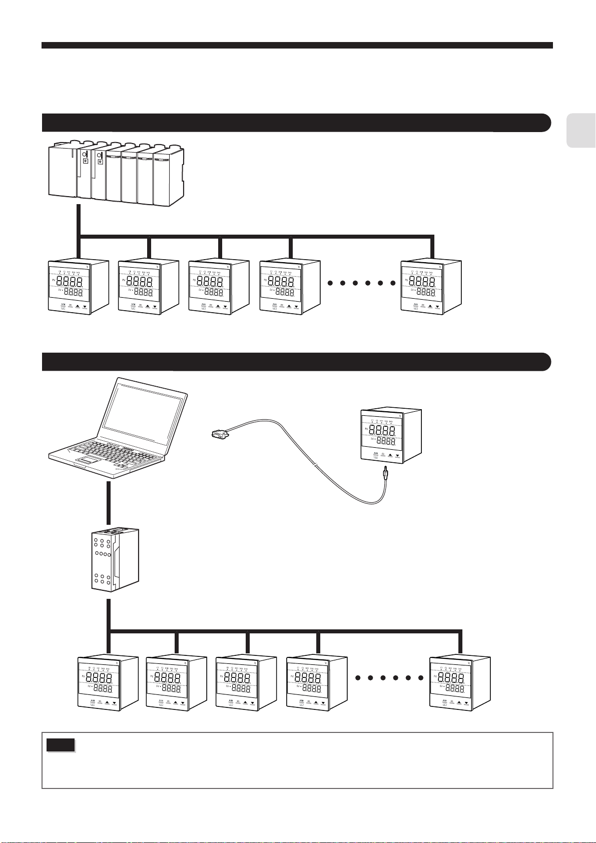
Connecting to a programmable controller
Programmable
controller
RS-485
PXG Series
Connecting to a personal computer
Chapter
1
Caution
Personal
computer
RS-232C
RS-232C to RS-485 converter
RS-485
PXG Series
RS-232C
PC loader communication cable
When using the RS-232C to RS-485 converter, check to make sure that the cable is properly connected between the
converter and master. Communication will not work properly if the connection is incorrect.
Also be sure to correctly set the communication settings (such as communication speed and parity) on the RS-232C
to RS-485 converter. Communication will not work properly if the settings are incorrect.
– 5 –
Page 7

Chapter
1
MEMO
– 6 –
Page 8

Chapter 2
Specifications
Communication Specifications – 8
Chapter
2
– 7 –
Page 9
Chapter
2
Communication Specifications
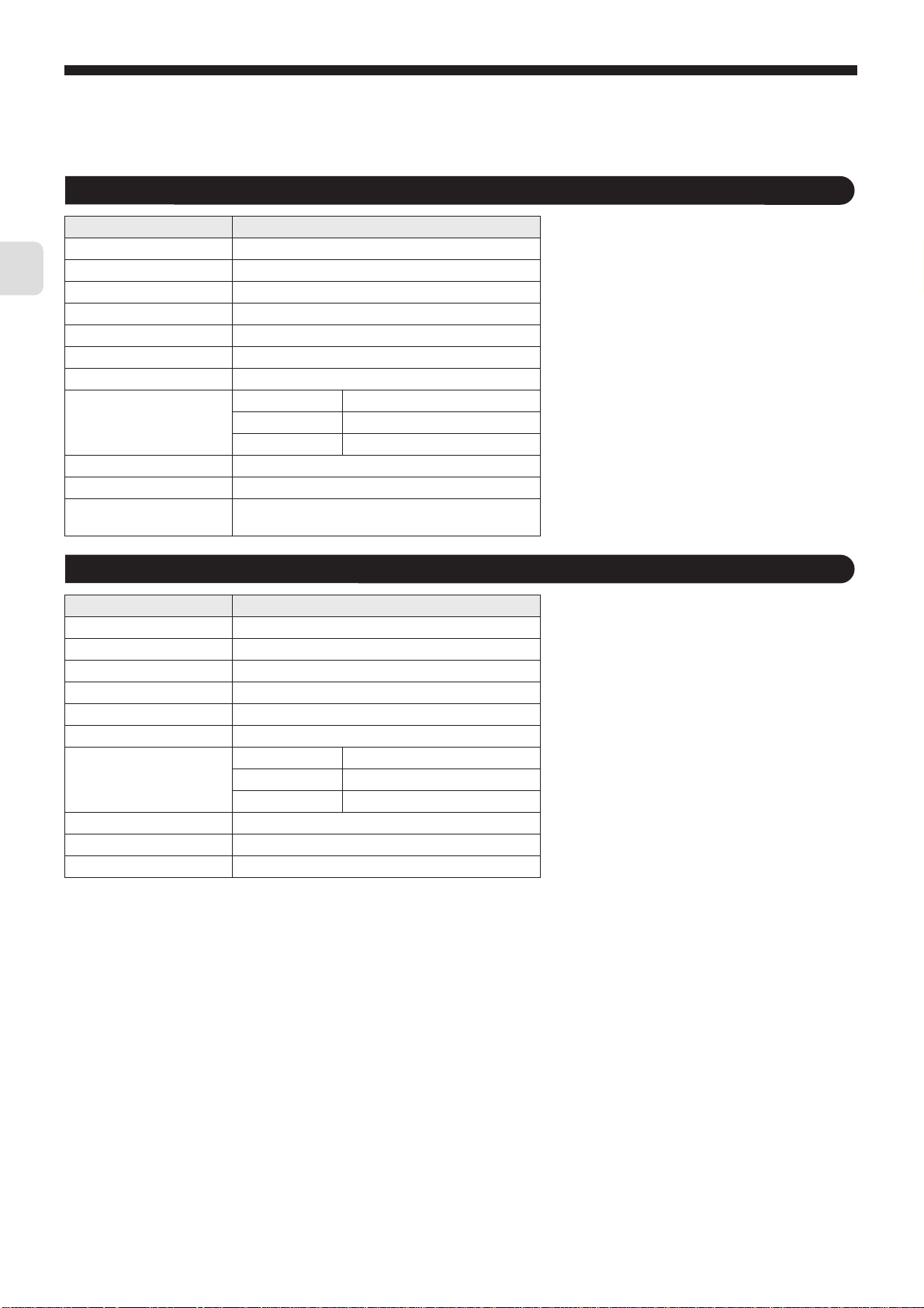
RS-485
Item Specifications
Electrical specifications EIA RS-485 compliant
Communication method Two wire system, half double-bit serial
Synchronous method Asynchronous
Connection status 1:N
Max. no. of connections 31 units
Communication distance Max 500m (total length)
Communication speed 9600bps, 19200 bps
Data format Data length 8 bits
Stop bit 1 bit
Parity None/Even/Odd (Selectable)
Transmission code HEX value (MODBUS RTU mode)
Error detection CRC-16
Insulation Functional insulation for the transmission area and
other areas (withstanding AC 500V)
PC Loader Interface
Item Specifications
Electrical specifications EIA RS232 C
Communication method 3wire system, half double-bit serial
Synchronous method Asynchronous
Connection status 1:1
Station No. 1 (Not to be changed)
Communication speed 9600 bps (Not to be changed)
Data format Data length 8 bits
Stop bit 1 bit
Parity none (Not to be changed)
Transmission code HEX value (MODBUS RTU mode)
Error detection CRC-16
Insulation Non-insulated internal circuit
– 8 –
Page 10

Chapter 3
Connection
Communication Terminal Configuration – 10
●
Wiring – 11
Chapter
3
– 9 –
Page 11
Chapter
3
Warning
Do not turn on power until all of the wiring is completely finished.
There is a risk of electrical shock or damage.
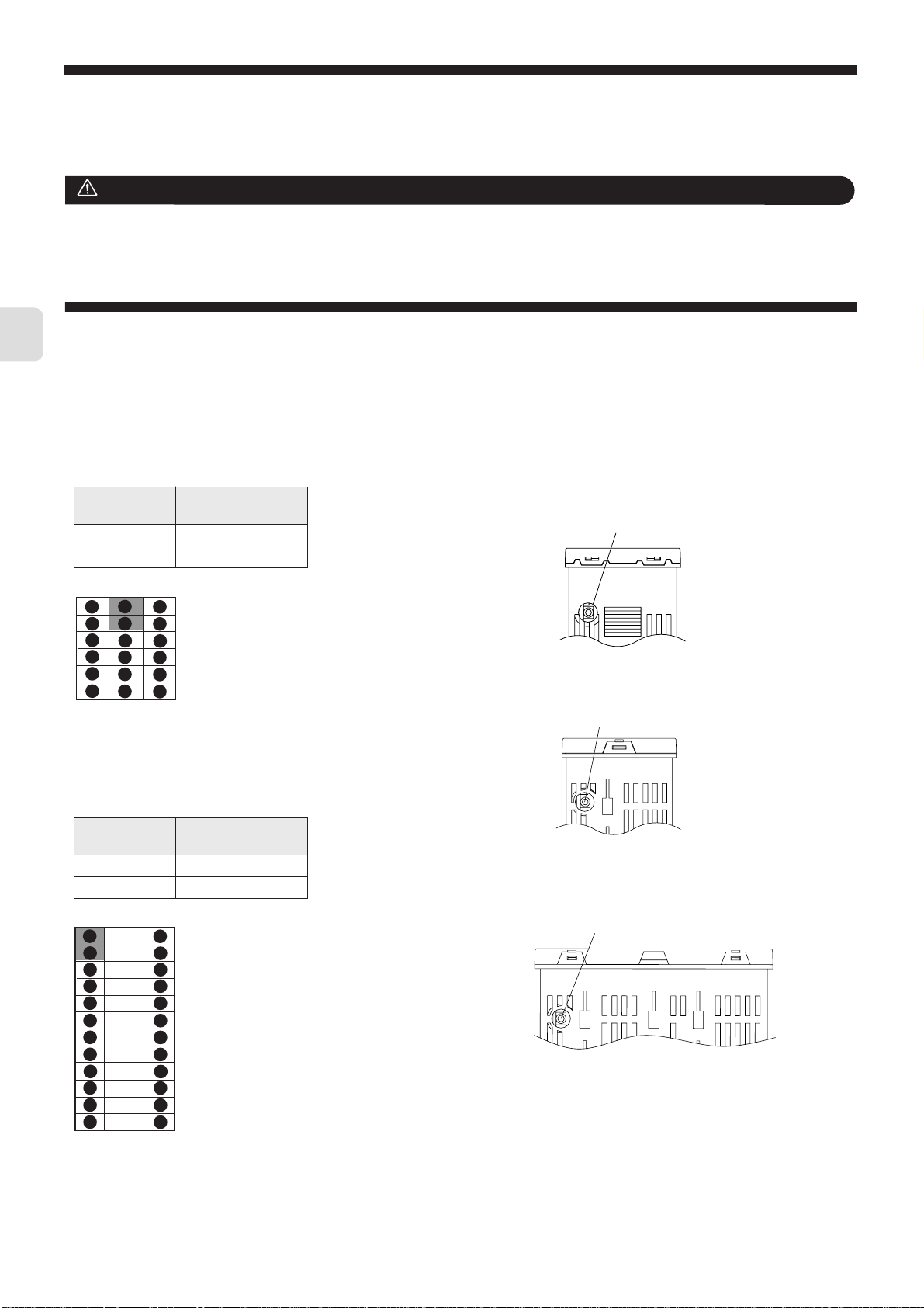
Communication T erminal Configuration
■ RS-485 (rear terminal)
PXG4
Terminal
Number
7 RS-485 +
8 RS-485 -
1
7
13
2
8
14
3
9
15
4
10
16
5
11
17
12
6
18
Signal Name
PXG5, PXG9
Terminal
Number
1 RS-485 +
2 RS-485 -
Signal Name
■ PC Loader Interface
(Bottom, φ2.5, three prong miniature jack)
PXG4
PC Loader Interface
PXG5
PC Loader Interface
PXG9
1
2
3
4
5
6
7
8
9
10
11
12
25
26
27
28
29
30
31
32
33
34
35
36
PC Loader Interface
– 10 –
Page 12
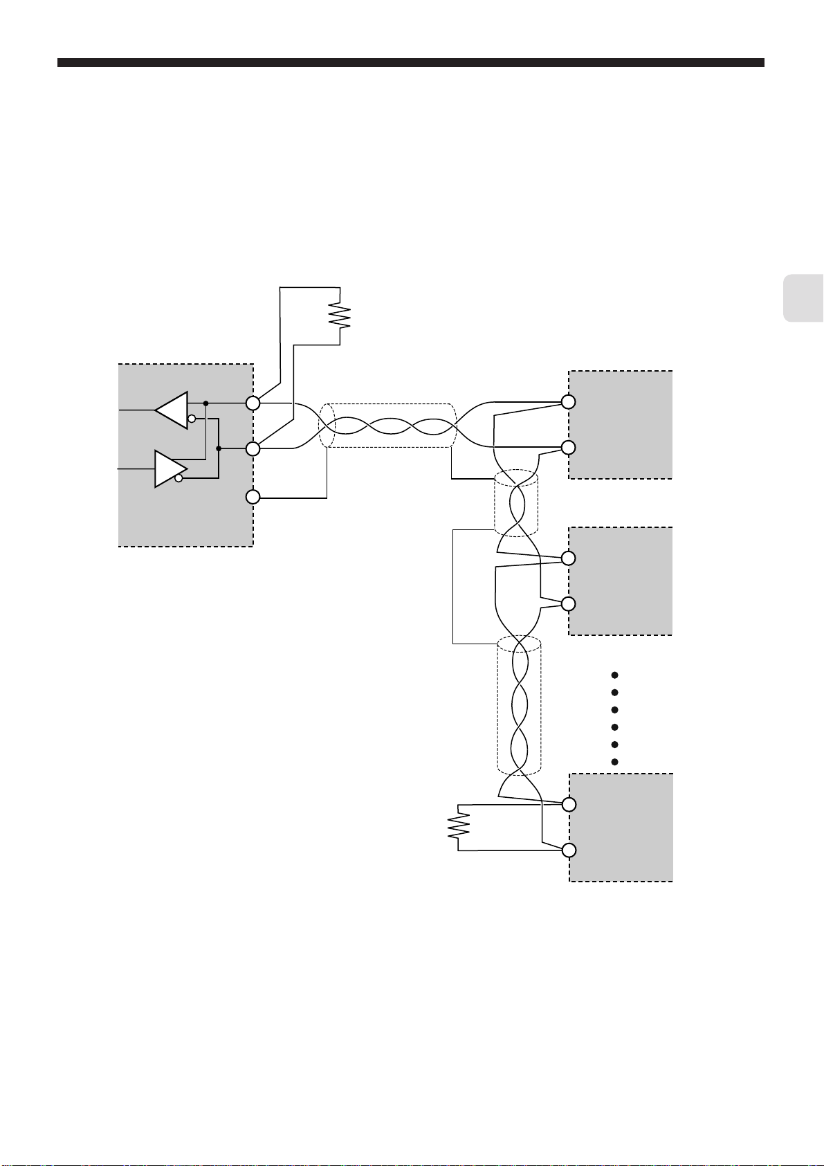
Wiring
■ RS-485
• Please use a shielded twist pair cable. (Recommended cable: KPEV-SB (made by The Furukawa Electric Co., Ltd.))
• The maximum cable length should be 500m. One master and up to thirty-one micro controllers (slaves) can be connected per
circuit.
• Terminate both ends of the circuit with a terminating resistance of 100
• Ground the shielded cable once towards the master side.
Ω (1/2W or more).
Chapter
Master
RS-485 interface
or
RS-485 side of
RS-232C to RS-485 converter
+
–
SG
Terminating resistance
100W (1/2W)
Shielded twist pair cable
3
Slave
+
–
PXG Series
+
–
PXG Series
+
Terminating resistance
100W (1/2W)
• SG does not have to be connected, but it can be used as an effective countermeasure against communication errors due to
noise.
– 11 –
–
PXG Series
Page 13
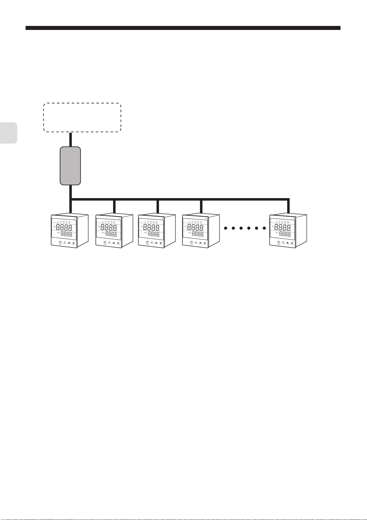
•
When using the micro controller in an area where the imposed noise level is expected to exceed 1000V, we recommend using
a noise filter on the master side as seen in the figure below .
[Noise filter] (recommended): ZRAC2203-11 (made by TDK Corporation)
Chapter
3
Programmable controller
or
Personal computer
+ RS-232C to RS-485 converter
Noise filter
RS-485
PXG Series
• If there are problems with EMC during communication, the noise level can be reduced by using a communication cable with a
ferrite core.
Ferrite core (recommended): ZCAT series (made by TDK Corporation)
MSFC series (made by Morimiya Electric Co., Ltd.)
– 12 –
Page 14
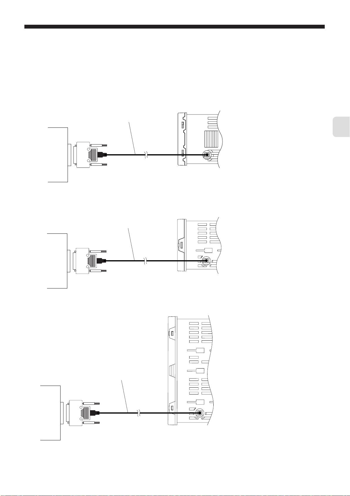
■ PC Loader Interface
• Use the PC loader communication cable (RS-232C) sold separately.
PXG4
PC loader communication cable (RS-232C)
Master side
Personal
computer
etc.
ZZPPXH1
RS-232C
TK4H4563
*
Chapter
3
PXG5
PXG9
Master side
Personal
computer
etc.
D-Sub 9 pin
PC loader communication cable (RS-232C)
ZZPPXH1
RS-232C
D-Sub 9 pin
TK4H4563
*
PXG4 Bottom view
PXG5 Bottom view
Master side
Personal
computer
etc.
PC loader communication cable (RS-232C)
ZZPPXH1
RS-232C
D-Sub 9 pin
TK4H4563
*
PXG9 Bottom view
– 13 –
Page 15

Chapter
3
MEMO
– 14 –
Page 16

Chapter 4
Setting Communication Parameters
Chapter
List of Setting Parameters – 16
●
Parameter Setting Procedure – 17
4
– 15 –
Page 17
Chapter
4
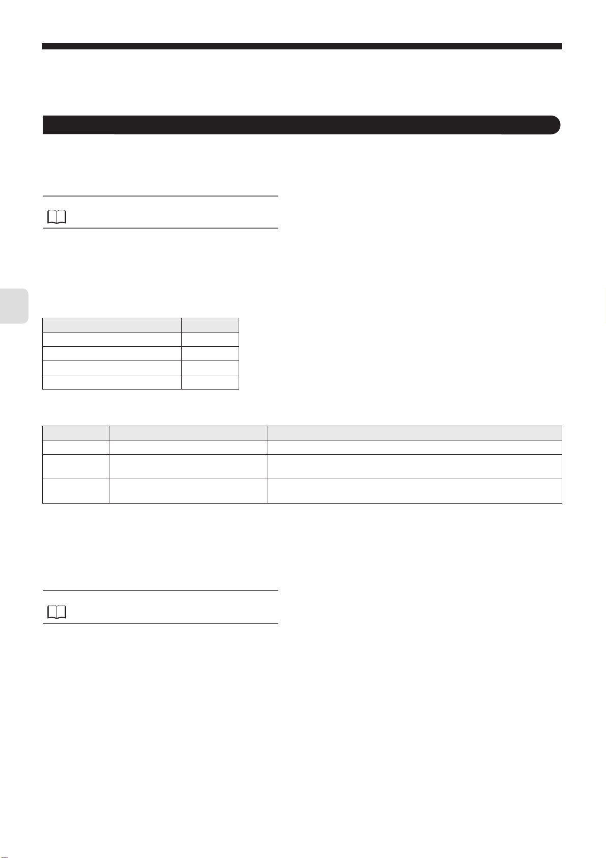
The following settings are required for proper communication between the master and micro controller units.
•
The communication parameters for the master and all of the units must be set the same.
•
During RS-485 communication, all of the micro controllers on a circuit must be set with different "Station No. (STno)" other
than "0 (zero)". (Multiple micro controllers must not have the same "Station No.".)
When using the PC loader interface, settings are not necessary on the main unit (the micro controller).
•
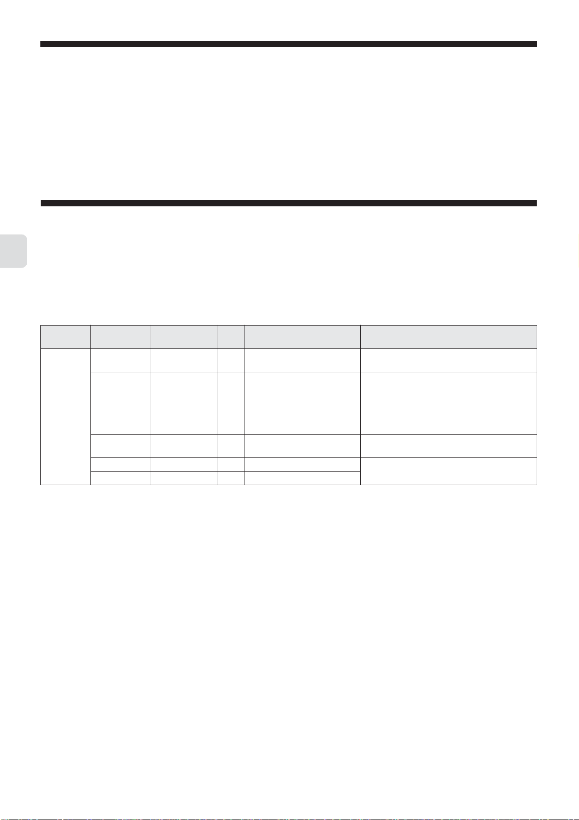
List of Setting Parameters
The setting parameters are shown in the chart shown below. Change the settings using the keys on the front of the micro
controller.
■
RS-485 (main unit side)
Parameter
channel
CoM Ch9
"
(CoM Ch9)
■
Loader interface (main unit side)
Parameter
display symbol
"
STno
"
CoM
"
"
SCC
Parameter name
" (STno)
" (CoM)
" (SCC)
– Data length 8 bits Fixed (cannot be changed) Set the master and all of the slaves with the
– Stop bit 1 bit Fixed (cannot be changed)
Station No. 1 0 to 255 Unit does not respond to communication when 0
baud rate/parity
settings
Communication
permissions
Initial
value
96od 96od (9600 bps/odd)
96Ev (9600 bps/even)
96no (9600 bps/none)
19od (19200 bps/odd)
19Ev (19200 bps/even)
19no (19200 bps/none)
rW r (read only)
rW (read and writable)
Setting range Remarks
is set.
This is the procedure to specify communications
speed and parity check.
Set the master and all of the slaves with the
same settings.
same settings.
The parameters do not need to be set. Set the loader software (master) with the following settings.
•
Communication speed: 9600 bps
•
Parity: none
– 16 –
Page 18
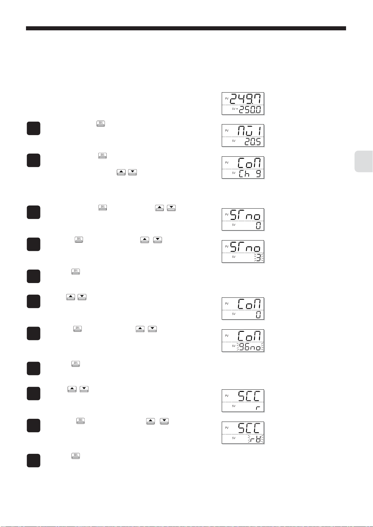
Parameter Setting Procedure
The following steps explain how to change the settings to station number "3", parity setting "9600bps/none", and communication
permissions "read and writable" as an example.
Press and hold the key to display " Mv1 ".
1
The MV1 of the monitoring screen is displayed.
Press and hold the key to display the setup mode operation
2
menu
("
oPE Ch 1
The communication menu is displayed.
(Note) If your micro controller does not have a communication function, "
model.
Press and hold the key, the use the keys to display
3
" STno ."
The station number is displayed.
Press the key, then use the keys to set station
4
number to "3" when the bottom part of the display begins to blink.
This sets the parameter to "3".
Press the key to confirm the setting.
"), then use the keys to display "
CoM Ch 9
5
Use the keys to select the parity setting (" CoM ").
6
Press the key, then use the keys to set the parity
7
setting to "96no" when the bottom part of the display begins to
blink.
The baud rate/parity setting is set to "9600 bps/none".
".
CoM Ch 9
Chapter
4
" will not be displayed. Please check with your
Press the key to confirm the setting.
8
Use the keys to select the communication permissions
9
(" SCC ").
Press the key, then use the keys to set the
10
communication permissions to "rW" when the bottom part of the
display begins to blink.
"read/write" is selected.
Press the key to confirm the setting.
11
– 17 –
Page 19

Chapter
4
Press the key to return to the operation mode PV/SV display.
12
Turn the power to the micro controller off and on again.
13
The changes to the communication parameters become effective after
the power turns off and on again.
– 18 –
Page 20

Chapter 5
MODBUS Communication Protocol
Overview – 20
●
Message Composition – 21
●
Calculating Error Check Code (CRC-16) – 24
●
Transmission Control Steps – 25
●
Precautions when Writing Data – 26
Chapter
5
– 19 –
Page 21
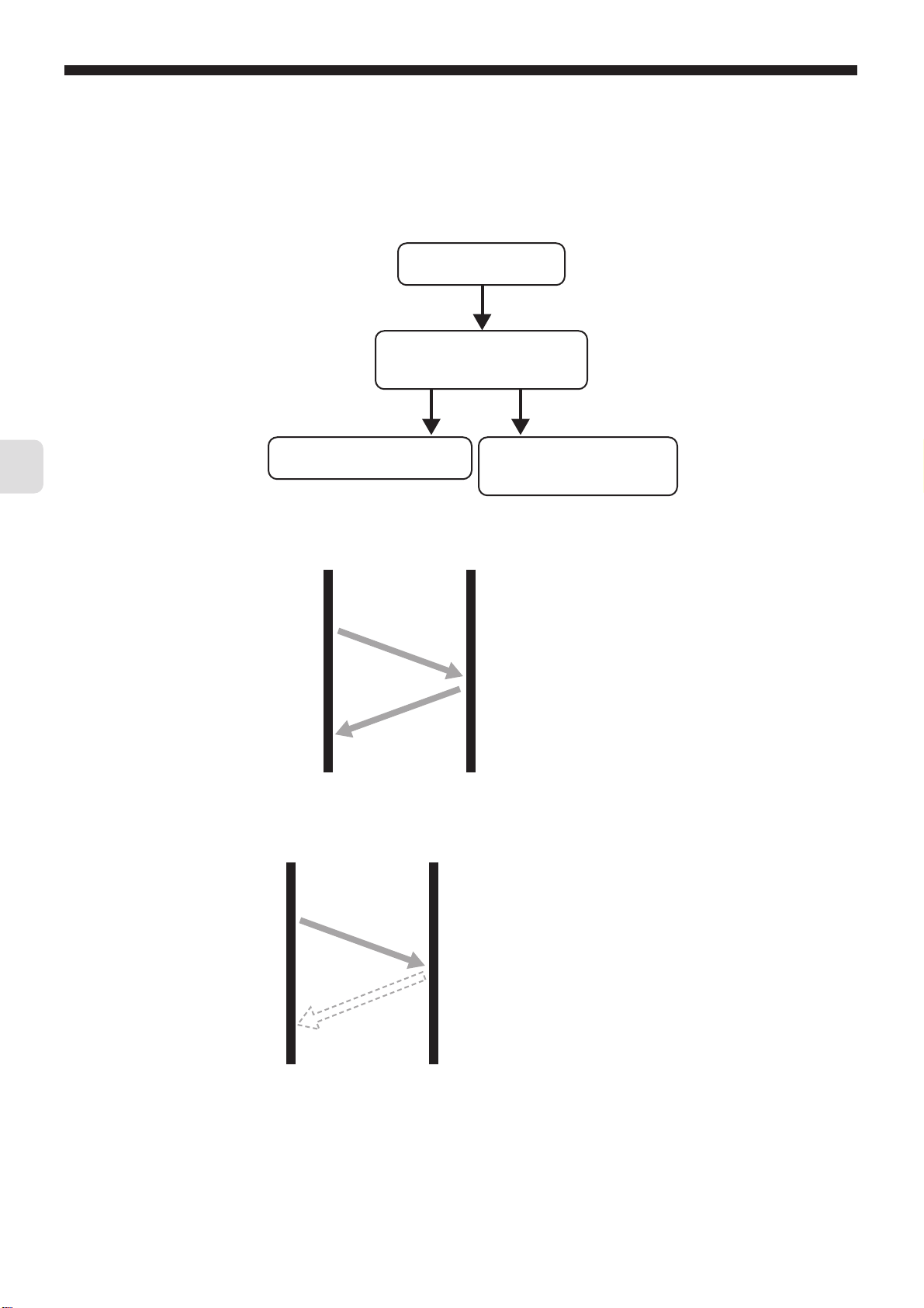
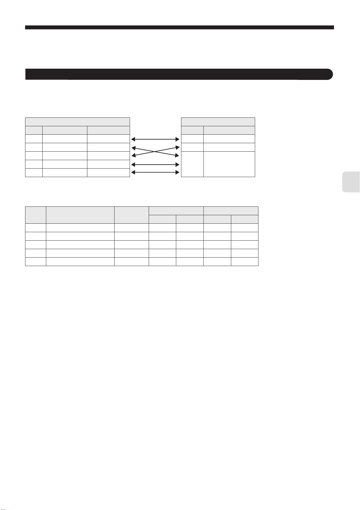
Overview
The communication system with the MODBUS protocol always operates using a method where the master first sends a command
message and the applicable slave replys with a response message .
The following describes the communication steps.
Master sends the command
message for the slave.
The slave checks whether the station
number in the received message is
the same as its own station number.
When it’s the same When it’s not the same
Chapter
5
The slave runs the command and
sends a response message.
The slave throws out the received
message and waits for the next
command message. (No reply.)
● When the station number in the command message is the same as the unit’s station number
Master Slave
Command Message
Station number is the same
Response Message
● When the station number in the command message is not the same as the unit’s station number
Master Slave
Command Message
Station number is not the same
The master can communicate with an individual slave when multiple slaves are connected on the same circuit by the station
number specified in the master’s command message.
– 20 –
Page 22

Message Composition
The command message and response message are composed of four parts: the station number, function code, data part, and
error check code. These four parts are sent in that order.
Field name No. of bytes
Station No. 1 byte
Function Code 1 byte
Data Part 2 to 125 bytes
Error Check Code (CRC-16) 2 bytes
The following describes each part of the message.
Station No.
This is the number specifying the slave. Commands can only be processed by slaves that have the same value set in the "STno"
parameter.
Refer to
For more about setting the "STno" parameter, see "Chapter 4,
Setting Communication Parameters" (p. 15).
Function Code
Chapter
5
This code specifies the function for the slave to perform.
Refer to
For more about function codes, see "Function Code" (p. 23).
Data Part
This data is required to run the function code. The composition of the data part is different depending on the function code.
Refer to
See "Chapter 6, Command and Transmission Frame Details"
(p. 27).
The data in the micro controller is assigned a coil number or resistor number. This coil number or resistor number is specified
when the data is read or written through communication.
The coil number or resistor number used by the message employs a relative address.
The relative address is calculated using the following formula.
Relative address = (last four digits of the coil number or resistor number) – 1
(Ex.) When a function code specifies resistor number "40003"
Relative address= (the last four digits of 40003) – 1
= 0002
is used in the message.
Error Check Code
This code detects whether there are errors (changes in the bits) during the signal transmission processes. MODBUS protocol
(RTU mode) uses CRC-16 (Cyclic Redundancy Check).
Refer to
For more about calculating CRC, see Section 5,
"Calculating Error Check Code (CRC-16)" (p. 24).
– 21 –
Page 23
Chapter
5
Slave Response
■ Normal Slave Response
The slave creates and replies with a response message for each command message. The response message has the same
format as the command message.
The contents of the data part are different depending on the function code.
Refer to
See "Chapter 6, Command and Transmission Frame Details".
■ Irregular Slave Response
If there are problems (such as specification of a nonexistent function code) with the contents of the command message other than
transmission error, the slave creates and replies with an error response message without following the command.
The composition of the error response message uses the value of the function code in the command message plus 80
below.
Field name No. of bytes
Station No. 1 byte
Function Code
+80
H
1 byte
Error Code 1 byte
Error Check Code (CRC-16) 2 bytes
The error code is shown as follows.
Error Code Contents Explanation
01
02
03
H
H
H
Faulty function code A nonexistent function code was specified. Please check the function code.
Faulty address for coil or resistor The specified relative address for the coil number or resistor number cannot be
used by the specified function code.
Faulty coil or resistor number The specified number is too large and specifies a range that does not contain
coil numbers or resistor numbers.
H, as seen
■ No Response
In the following situations, the slave will ignore the command message and not send a response message.
• The station number specified by the command message is not the same as the slave’s specified station number.
• The error check code does not correspond, or a transmission error (such as parity error) is detected.
• The interval between the data comprising the message is empty for more than 24 bit time.
Refer to
See Section 5 "Transmission Control Steps" (p. 25).
• The slave station number is set to "0".
– 22 –
Page 24
Function Code
For MODBUS protocol, coil numbers or resistor numbers are assigned by the function code, and each function code
only works for the assigned coil number or resistor number.
The correspondence between the function code and the coil number or resistor number is as follows.
Function Code
Coil Number, Resistor Number
Code Function Target Number Contents
Read (continuous) Input relay 1xxxx Read bit data
02
H
03
Read (continuous) Hold resistor 3xxxx Read word data
H
04
Read (continuous) Input resistor
H
Write Hold resistor
H
10
Write (continuous) Retention resistor
H
4xxxx Read/write word data06
The message length for each function is as follows.
[unit: byte]
*
*
*
*
*
Code Contents
02
03
04
06
10
Read bit data (read-only) 8 bit
H
Read word data 60 words
H
Read word data (read-only) 37 words
H
Write word data 1 word 8888
H
Continuously write word data 60 words
H
Assignable
Data Number
1
Command Message Response Message
Minimum Maximum Minimum Maximum
8866
1
1
1
887125
88779
11 129 8 8
1: "Assignable Data Number" above is limited by the data number that the micro controller assigned to the coil number or
address number.
(Excluding function code 06
H
).
Chapter
5
– 23 –
Page 25

Chapter
5
Calculating Error Check Code (CRC-16)
CRC-16 is a 2-byte (16-bit) error check code. The calculation r ange extends from the start of the message (station number) to the
end of the data part.
The slave calculates the CRC of the received message and ignores the message if this value is not the same as the received
CRC code.
CRC-16 is calculated as follows.
Start
* Description of Variables
Set CR to FFFF
Exclusive-or (XOR) runs on each character of J (one byte) for CR
and the specified message, and sets that result to CR.
H (hexadecimal)
Set J = 1
Set K = 1
CR : CRC error check data (2 byte)
J:Command message calculation
character digit
K:No. of times to check CR calculation
Is the right-hand
bit for CR 1?
YES
After CR has been adjusted one bit to the right, A001
run and set that result to CR.
Add 1 to K
NO
NO
Has calculation
finished 8 times ?
J > 8
YES
Add 1 to J
Has every character
been calculated ?
J > Number of characters
NO
H and XOR
(Calculations occur in the order
command message station number,
function code, and data.)
Adjust CR one bit
to the right.
YES
Complete
The CR calculation result is added
onto the end of the command
message in LOW or HIGH order.
– 24 –
Page 26

Transmission Control Steps
Master Communication Method
Start communication from the master while following the rules below.
1. The command message, must be sent after an empty space of at least 48 bit time.
2. The interval between each byte in a command message should be less than 24 bit time.
3. After sending a command message, for less than 24 bit time the master will enter receiving standby.
4. After receiving the response message, the next command message must be sent after at least 48 bit time. (Similar to #1.)
5. For safety reasons, create a framework where the master checks the response message, and if there is no response or an
error occurs, retry at least three times.
Caution
The definitions written above are for the minimum required value. For safety reasons, we recommend creating a
master side program that keeps margins two to three times as large. For a concrete example, with 9600 bps, we
recommend programming a blank state (#1 above) of at least 10ms, and the interval between bytes (#2 above) and
switching time from sending to receiving (#3 above) within 1 ms.
Explanation
■
Frame Detection
This communication system uses a two-wire RS-485 interface, and the circuit can therefore enter one of the following two states.
Empty state (no data on the circuit)
•
•
Communication state (data running on the circuit)
The units connected on the circuit start in receiving state and monitor the circuit. When a blank state appears on the circuit for at least
24 bit time, the unit detects the end of the previous frame, and within the next 24 bit time, enters receiving standby. When data
appears on the circuit, the unit begins receiving data, and once another blank state of at least 24 bit time is detected, that frame is
ended. In other words, the data on the circuit from the first time that a 24 bit time blank state appears to the second time one appears
is loaded as one frame (a bundle of data). Therefore, one frame (command message) must be sent while following the rules below.
Before sending the command message, leave an empty space of at least 48 bit time.
•
•
The interval between each byte in a command message should be less than 24 bit time.
■
Micro controller Response
After the micro controller detects the frame (detects blank states at least 24 bit time long), that frame is used to send a command
message. When a command message is sent locally, the response message is returned, but the processing time is about 1 to 30
ms. (The time may change depending on the contents of the command message. ) Therefore, one frame (command message)
must be sent while following the rules below.
•
After sending a command message, for less than 24 seconds the master will enter receiving standby.
Master
POL1
Slave
Chapter
5
Interval of at least 5ms required
(at least 10ms recommended)
1 to 30ms
POL1 response data
POL2
1 to 30ms
POL2 response data
– 25 –
Page 27

Chapter
5
Precautions when Writing Data
PXG contains internal nonvolatile memory (EEPROM) that is used to save the setting parameters. The data written to the
nonvolatile memory (EEPROM) remains even after the power for PXG is turned off. Parameters that are written via
communication are automatically saved in the internal nonvolatile memory (EEPROM). However, please note that there are two
limitations as follows.
Caution
1. There is a limit to the number of times that data can be transferred to the nonvolatile memory (EEPROM)
(100,000 times). Data cannot be guaranteed if written more than 100,000 times.
Be careful not to transfer unnecessary data when writing data via communication.
In particular, when constructing a communication system with master POD (such as a touch panel), make sure
that the POD writing and trigger settings are appropriate.
Avoid writing at fixed cycles.
2. Writing to the nonvolatile memory (EEPROM) takes several milliseconds. If the power for PXG is turned off
during this operation, the data saved to the nonvolatile memory (EEPROM) may be corrupted.
Wait several seconds after writing data before turning off the power.
In particular, when writing data in a cycle from master device, there is a greater danger of the writing timing and
power shutoff timing coinciding.
Avoid writing at fixed cycles.
– 26 –
Page 28

Chapter 6
Command and Transmission Frame
Details
Reading Data – 28
●
Writing Data – 34
Chapter
6
– 27 –
Page 29

Reading Data
Reading Read-Only Bit Data (Function Code: 02H)
The unit reads bit data continuously for the specified number of bits from the first number to start reading from.
The slaves systematically send the read data in 8-bit units.
Caution
Function Code 02H
Max. No. of Bits to Read in One Message 8 bits
Relative Address 0000H to 000CH
Coil Number 10001H to 10013H
Message Composition
When the number of bits to be read is not a multiple of eight, unrelated bits (on the MSB side) all become "0".
Chapter
6
Command Message (bytes)
Station No.
Function Code
Number to Start Reading
(Relative Address)
No. of Bits to Read
CRC Data
■
Bit Data to Read List
MSB LSB
00000000
State of last 1 bit
Upper
Lower
00H
Lower
Upper
Lower
Master Slave
State of first 1 bit
Reply Message Composition (bytes)
Station No.
Function Code
No. of Bytes to Read (01H)
State of first 8 bits
CRC Data
Upper
Lower
– 28 –
Page 30

Example of Transmitting a Message
This following example explains how to read ALM1 and ALM2 on station number 31.
• ALM1 detection data bit Relative address: 0000H Data number: 2H
• ALM2 detection data bit Relative address: 0001H
Command Message (bytes)
Station No. 1FH
Function Code 02H
No. to Start Reading
(Relative Address)
No. of Bits to Read Upper 00H
CRC Data Upper FAH
■
Meaning of Read Data
Upper 00H
Lower 00H
Lower 02H
Lower 75H
MSB LSB
00000001
ALM2 OFF state
Master Slave
ALM1 ON state
Response Message (bytes)
Station No. 1FH
Function Code 02H
No. of Bytes to Read 01H
State of first 8 bits 01H
CRC Data Upper 66H
Lower 60H
Chapter
6
– 29 –
Page 31

Reading Word Data (Function Code: 03H)
The unit reads word data continuously for the specified number of words from the first number to start reading from.
The slave forwards the read word data from the upper number of bytes to the lower number.
Function Code 03H
Max. No. of Words to Read in One Message 60 words
Relative Address 0000H to 0276H 03E8H to 065EH
Resistor Number 40001 to 40628 41001 to 41628
Contents
Message Composition
Internal Calculation
Value
Engineering Unit
Chapter
6
Command Message Composition
(bytes)
Station No.
Function Code
No. to Start Reading
(Relative Address)
No. of Words to Read
(1 to 60 words)
CRC Data
Upper
Lower
Upper
Lower
Upper
Lower
Master Slave
Reply Message Composition (bytes)
Station No.
Function Code
No. of Bytes to Read
(No. of Words to Read x 2)
First Word Data
Contents
Next Word Data
Contents
Last Word Data
Contents
CRC Data
Upper
Lower
Upper
Lower
Upper
Lower
Upper
Lower
■
Meaning of Read Word Data
MSB LSB
First Word Data upper byte
First Word Data lower byte
Next Word Data upper byte
Next Word Data lower byte
Last Word Data upper byte
Last Word Data lower byte
– 30 –
Page 32

Example of Transmitting a Message (For Engineering Unit)
The message is composed as follows when reading the PV input lower limit and PV input upper limit from station number 2.
• PV Lower Limit Relative Address: 03F9H
Master Slave
Command Message (bytes)
Station No. 02H
Function Code 03H
No. to Start Reading
(Relative Address)
No. of Words to Read
CRC Data
■
Meaning of Read Data
Upper 03H
Lower F9H
Upper 00H
Lower 02H
Upper 14H
Lower 4DH
PV Input Lower Limit 00 00H = 0
PV Input Upper Limit 01 90H = 400
Response Message (bytes)
Station No. 02H
Function Code 03H
No. of Bytes to Read 04H
First Word Data
Contents
Next Word
Data Contents
CRC Data
Upper 00H
Lower 00H
Upper 01H
Lower 90H
Upper C8H
Lower CFH
Chapter
6
If Decimal Point Position = 0, then the PV input upper limit and lower limit are as follows.
PV Lower Limit = 0°C
PV Upper Limit = 400°C
For more about the internal calculation value, engineering unit,
Refer to
and decimal point see
"Chapter 7, Address Map and Data Format" (p. 39).
– 31 –
Page 33

Reading Read-Only Word Data (Function Code: 04H)
The unit reads word data continuously for the specified number of words from the first number to start reading from.
The slave forwards the read word data from the upper number of bytes to the lower number.
Function Code 04H
Max. No. of Words to Read in One Message 37 bytes
Relative Address 0000H to 0064H 03E8H to 044CH
Resistor Number 30001 to 30100 31001 to 31100
Contents Internal Calculation Value Engineering Unit
Message Composition
Chapter
6
Command Message Composition
(bytes)
Station No.
Function Code
No. to Start Reading
(Relative Address)
No. of Words to Read
(1 to 15 words)
CRC Data
Upper
Lower
Upper
Lower
Upper
Lower
Master Slave
Reply Message Composition (bytes)
Station No.
Function Code
No. of Bytes to Read
(No. of Words to Read x 2)
First Word Data
Contents
Next Word Data
Contents
Last Word Data
Contents
CRC Data
Upper
Lower
Upper
Lower
Upper
Lower
Upper
Lower
■ Meaning of Read Word Data
MSB LSB
First Word Data upper byte
First Word Data lower byte
Next Word Data upper byte
Next Word Data lower byte
Last Word Data upper byte
Last Word Data lower byte
– 32 –
Page 34

Example of Transmitting a Message (Internal Calculation Data)
The message is composed as follows when reading the PV input value from station number 1.
• PV value relative address: 0000H Number of data: 01H
Command Message (bytes)
Station No. 01H
Function Code 04H
No. to Start Reading
(Relative Address)
No. of Bits to Read
CRC Data
Upper 00H
Lower 00H
Upper 00H
Lower 01H
Upper 31H
Lower CAH
Master Slave
■ Meaning of Read Data
Word Data Contents 03 46H = 838 (8.38% FS)
When the input range is 0 to 400°C
PV = 33.5°C (= 8.38% FS x 400 (input range width))
For more about the internal calculation value, engineering unit,
Refer to
and decimal point see
"Chapter 7, Address Map and Data Format" (p. 39).
Example of Transmitting a Message (For Engineering Unit)
Response Message (bytes)
Station No. 01H
Function Code 04H
No. of Bytes to Read 02H
First Word Data
Contents
CRC Data
Upper 03H
Lower 46H
Upper 38H
Lower 32H
Chapter
6
The message is composed as follows when reading the PV value from station number 1.
• PV value relative address: 03E8H Number of data: 01H
Command Message (bytes)
Station No. 01H
Function Code 04H
No. to Start Reading
(Relative Address)
No. of Words to Read
CRC Data
Upper 03H
Lower E8H
Upper 00H
Lower 01H
Upper B1H
Lower BAH
Master Slave
Response Message (bytes)
Station No. 01H
Function Code 04H
No. of Bytes to Read 02H
First Word Data
Contents
CRC Data
■ Meaning of Read Data
Word Data Contents 01 4FH = 335
When the decimal point position = 1
PV = 33.5°C
For more about the internal calculation value, engineering unit,
Refer to
and decimal point see
"Chapter 7, Address Map and Data Format" (p. 39).
Upper 01H
Lower 4FH
Upper F9H
Lower 54H
– 33 –
Page 35

Chapter
6
Writing Data
Writing Word Data (1 word, function code: 06H)
This writes the specified data to the specified number for word data. The master sends the data to be written from the upper
number of bytes to the lower number.
Function Code 06H
Max. No. of Bits to Read in One Message 1 words
Relative Address 0001H to 0274H 03E9H to 065CH
Resistor Number 40002 to 40628 41002 to 41628
Contents Internal Calculation
Value
Message Composition
Master Slave
Command Message Composition
(bytes)
Station No.
Function Code
Specified Write Number
(Relative Address)
Word Data to Write
CRC Data
Upper
Lower
Upper
Lower
Upper
Lower
Engineering Unit
Response Message Composition
(bytes)
Station No.
Function Code
Specified Write
Number
(Relative Address)
Word Data to
Write
CRC Data
Upper
Lower
Upper
Lower
Upper
Lower
– 34 –
Page 36

Example of Transmitting a Message
This example explains how to set PID parameter "P" to 100.0 (1000D = 03E8H) on station number 1.
Parameter "P" relative address: 0005H (internal calculation value table)
03EDH (initial value table)
Master Slave
Command Message (bytes)
Station No. 01H
Function Code 06H
Specified Write
Number
(Relative Address)
Word Data to Write
CRC Data
Upper 00H
Lower 05H
Upper 03H
Lower E8H
Upper 99H
Lower 75H
Response Message (bytes)
Station No. 01H
Function Code 06H
Specified Write
Number
(Relative Address)
Write Specification
State
CRC Data
Upper 00H
Lower 05H
Upper 03H
Lower E8H
Upper 99H
Lower 75H
Chapter
6
Point
For more about the internal calculation value, engineering unit, and decimal point see "Sent Data Format" (p. 40).
– 35 –
Page 37

Chapter
Writing Continuous Word Data (Function code: 10H)
This writes continuous word information for a number of written words from the first number for writing.
The master sends the data to be written from the upper number of bytes to the lower number.
Function Code 10H
Max. No. of Bits to Read in One Message 60 words
Relative Address 0000H to 0077H 03E8H to 045FH
Resistor Number 40001 to 40120 41001 to 41120
Contents Internal Calculation
Value
Message Composition
Master Slave
Engineering Unit
6
Command Message Composition (bytes)
Station No.
Function Code
Specified Write
Number (Relative
Address)
No. of Words to Write Upper
No. of Bytes to Write
First Word Data to
Write
Next Word Data to
Write
Last Word Data to
Write
CRC Data Upper
Upper
Lower
Lower
Upper
Lower
Upper
Lower
Upper
Lower
Lower
}
1 to 60
} No. of Words
to Write x 2
Reply Message Composition (bytes)
Station No.
Function Code
Specified Write
Number (Relative
Address)
No. of Words to
Write
CRC Data Upper
Upper
Lower
Upper
Lower
Lower
■ Meaning of Read Word Data
MSB LSB
First Word Data upper byte
First Word Data lower byte
Next Word Data upper byte
Next Word Data lower byte
Last Word Data upper byte
Last Word Data lower byte
– 36 –
Page 38

Example of Transmitting a Message (Internal Calculation Data)
The message is composed as follows when writing the following PID parameters to station number 1.
P = 100.0 (= 1000D = 03E8H)
I = 10 (= 100D = 0064)
D = 5.0 (= 50D = 0032H)
•Parameter “PPPP” relative address: 0005H, Data number: 03H
Command Message (bytes)
Station No. 01H
Function Code 10H
Specified Write
Number (Relative
Address)
No. of Words to
Write
No. of Bytes to Write 06H
First Word Data to
Write
Next W ord Data to
Write
Last Word Data to
Write
CRC Data Upper 56H
Upper 00H
Lower 05H
Upper 00H
Lower 03H
Upper 03H
Lower E8H
Upper 00H
Lower 64H
Upper 00H
Lower 32H
Lower BEH
Master Slave
Response Message (bytes)
Station No. 01H
Function Code 10H
Specified Write
Number
(Relative Address)
Write Specification
State
CRC Data
Upper 00H
Lower 05H
Upper 00H
Lower 03H
Upper 90H
Lower 09H
Chapter
6
Point
Refer to
The decimal point cannot be included in the sent data, so data such as “100.0” above is sent as “1000”.
For each type of send data format, see “Chapter 7, Address
Map and Data Format” (p. 39).
– 37 –
Page 39

Chapter
6
MEMO
– 38 –
Page 40

Chapter 7
Address Map and Data Format
Data Format – 40
●
Internal Calculation Value Data Address Map – 42
Chapter
7
– 39 –
Page 41

Data Format
Sent Data Format
The MODBUS protocol used by this equipment employs RTU (Remote Terminal Unit) mode. The data is sent as "numerical
value", not as ASCII code.
Internal Calculation Value and Engineering Unit
In this unit, parameter data and data dependent on an input range can handle the following two types of data.
Internal Calculation Value: Values listed as percentages of the input range (0.00 to 100.00, without decimal point)
Engineering Unit: Values subjected to scaling to actual values depending on the input range
"Engineering Unit" data is handled as the address (resister number) of 1000 added to the address (resister number) for "Internal
Calculation Value".
(Ex.) The value is calculated as follows when the full scale is 400°C and the PV value is "150".
Class Resistor Number Data (HEX) Data
Internal Calculation Value 30001 0EA6 (H)
Engineering unit 31001 0096 (H) 150
→
3750 (37.5%)
Chapter
7
The PV value is received as follows.
37.50 (%) x 400 (full scale °C) = 150 °C
Data not dependent on an input range the same data in both addresses.
Also, bit data cannot be handled in this manner. (Not effective for addresses with 1,000 added.)
Refer to
For more about data dependent on an input range, see
"Chapter 7 Address Map and Data Format" (page 39).
Caution
(Ex.) When changing the input range from 0 to 400 to 0.0 to 400.0
■ Operating the keys on the front of the equipment
Change the position of the decimal point ("PP
PPvvvvdddd
"PP
■ Changing by communication
Set the decimal position parameter ("PP
upper limit ("PP
PPvvvvdddd
"PP
PPvvvvbbbb
"PP
PPvvvvFFFF
"PP
Pay attention to the position of the decimal point when changing the input range by writing with communication. When
changing the position of the decimal point by writing with communication, change the lower limit and upper limit of the
input range at the same time.
" = 0 → 1 (or 2)
PPvvvvFFFF
").
" = 0 → 1
" = 0 → 0
" = 400 → 4000
PPvvvvdddd
") in the setup menu ("SS
PPvvvvdddd
"), as well as the corresponding values for PF input lower limit ("PP
SSEEEETTTT CCCChhhh 6666
").
PPvvvvbbbb
") and PV input
Managing the Decimal Point
Some of the internally stored data may contain may digits lower than the decimal point on the front displa y. Also, the decimal point
is not added to sent data.
Carry out processes for the decimal point position (erasing the decimal point when sending data and adding the decimal point
when receiving data).
Attention must be paid to the position of the decimal point for data where the parameters are dependent on a range in "Chapter 7
Address Map and Data Format". Refer to Address Map.
– 40 –
Page 42

Data during Input Error
For situations such as overrange, underrange, and input breaks where "UU
becomes 105% or -5% of the input range.
Input errors can be detected via communication using "resistor number 30008 (or 31008): Input/Unit Error Status".
UUUUUUUUUUUUUU
" or "LL
LLLLLLLLLLLLLL
" display on the front, read PV value
Written Data
When writing data to each parameter, set that written data within the range for the data. PXG can accept written data outside of
the range, but do so with care as correct operations are not guaranteed.
Addresses Not Written
Do not write to addresses that are not public. Doing so may cause damage.
Chapter
7
– 41 –
Page 43

Internal Calculation Value Data Address Map
Handles data dependent on an input range as an internal value before scaling (0.00 to 100.00%).
See "Operation Manual" for more details about individual parameter functions and settings ranges.
Bit Data (read only): function code [02 (H)]
Chapter
7
Relative
address
0000H 10001 bit DO1 OUTPUT
00001H 10002 bit DO2 OUTPUT
00002H 10003 bit DO3 OUTPUT
00003H 10004 bit DO4 OUTPUT
00004H 10005 bit DO5 OUTPUT
00008H 10009 bit DO1 Lamp
00009H 10010 bit DO2 Lamp
0000AH 10011 bit DO3 Lamp
0000BH 10012 bit DO4 Lamp
H 10013 bit DO5 Lamp
0000C
Coil
Number
Type
Memory
contents
ON/OFF
ON/OFF
ON/OFF
ON/OFF
ON/OFF
ON/OFF
ON/OFF
ON/OFF
ON/OFF
ON/OFF
Read data
0: DO1 OFF
1: DO1 ON
0: DO2 OFF
1: DO2 ON
0: DO3 OFF
1: DO3 ON
0: DO4 OFF
1: DO4 ON
0: DO5 OFF
1: DO5 ON
0: DO1 Lamp OFF
1: DO1 Lamp ON
0: DO2 Lamp OFF
1: DO2 Lamp ON
0: DO3 Lamp OFF
1: DO3 Lamp ON
0: DO4 Lamp OFF
1: DO4 Lamp ON
0: DO5 Lamp OFF
1: DO5 Lamp ON
Dependent
on range
Remarks/
related
parameters
– 42 –
Page 44

Word Data (read/write): function code [03 (H), 06 (H), 10 (H)]
Operation (Ch1)
Parameter
display
nn
MMMMaaaann
"
"
YY
SSSSTTTTbbbbYY
"
MM
rrrrEEEEMM
"
"
GG
PPPPrrrrGG
"
"
tt
AAAAtt
"
"
Parameter
name
MAn Switches to manual mode 0084
STbY Switches between RUN
"
Contents
and standby
rEM Switches to remote mode 0074
PrG Ramp/soak controls
Command
AT Auto-tuning
run command
Relative
address
0003
0051
0004
Resistor Number
Internal
H
40121 41121 Word 0: oFF (during auto)
Engineering
Type Read data
unit
1: on (during manual)
H
40004 41004 Word 0: oFF (during RUN)
1: on (during standby)
H
40117 41117 Word
0: LoCL (during Local)
1: rEM (during Remote)
H
40082 41082 Word 0: oFF (during stop)
1: rUn (during run)
2: hLd (during hold)
H
40005 41005 Word 0: oFF
1: rUn
Written data
range
0: oFF (auto)
1: on (manual)
0: LoCL (Local)
1: rEM (Remote)
0: oFF (stop)
1: rUn (run)
2: hLd (hold)
Factory
Setting
oFF
oFF
LoCL
oFF
oFF
Dependent
on range
2: Low
hh
LLLLAAAACCCChh
"
nn
SSSSvvvvnn
"
"
(note 1)
LACh Cancels the DO output
"
latch Command
Svn
Selectable SV numbers
00A0
00DC
H
40161 41161 Word 0: oFF
1: rST (latch reset)
H
40221 41221 Word 0: Sv0 (Local SV)
1: Sv1 (SV = SV-1)
2: Sv2 (SV = SV-2)
oFF
Sv0
3: Sv3 (SV = SV-3)
4: Sv4 (SV = SV-4)
5: Sv5 (SV = SV-5)
6: Sv6 (SV = SV-6)
7: Sv7 (SV = SV-7)
8: di : SV = choose Di
PPPPLLLLnnnn11
"
PLn1
11
"
Currently selected PID No.
00DD
H
40222 41222 Word 0: Pid0 (PID group local)
Pid0
1: Pid1 (PID group No. 1)
2: Pid2 (PID group No. 2)
3: Pid3 (PID group No. 3)
4: Pid4 (PID group No. 4)
5: Pid5 (PID group No. 5)
6: Pid6 (PID group No. 6)
7: Pid7 (PID group No. 7)
8: di (PID group Di selection)
AAAALLLL11
"
AAAALLLL1111LL
"
AL1 ALM1 set value or A1-L 00A2
11
"
AL1L AL1L set value Word 0% to 100% FS (absolute alarm)
LL
"
H
40163 41163 Word 0% to 100% FS 10°C
-100% to 100 % FS (deviation alarm)
AAAALLLL1111hh
"
AL1h AL1h set value 00A3
hh
"
H
40164 41164 Word 0% to 100% FS (absolute alarm)
-100% to 100 % FS (deviation alarm)
AAAALLLL22
"
AAAALLLL2222LL
"
AL2 ALM2 set value or A2-L 00A9
22
"
AL2L AL2L set value Word 0% to 100% FS (absolute alarm)
LL
"
H
40170 41170 Word 0% to 100% FS 10°C
-100% to 100 % FS (deviation alarm)
AAAALLLL2222hh
"
AL2h AL2h set value 00AA
hh
"
H
40171 41171 Word 0% to 100% FS (absolute alarm)
-100% to 100 % FS (deviation alarm)
AAAALLLL33
"
AAAALLLL3333LL
"
AL3 ALM3 set value or A3-L 00B0
33
"
AL3L AL3L set value Word 0% to 100% FS (absolute alarm)
LL
"
H
40177 41177 Word 0% to 100% FS 10°C
-100% to 100 % FS (deviation alarm)
AAAALLLL3333hh
"
AL3h AL3h set value 00B1
hh
"
H
40178 41178 Word 0% to 100% FS (absolute alarm)
-100% to 100 % FS (deviation alarm)
Note 1: If SV is changed using the front keys of the equipment and “SVn” is changed via communication at the same time, the SV set from the
front panel may be reflected to the SV number changed via communication.
Chapter
7
– 43 –
Page 45

Parameter
display
"
"
44
AAAALLLL44
"
LL
AAAALLLL4444LL
Parameter
name
AL4 ALM4 set value or A4-L 00B7
AL4L AL4L set value Word 0% to 100% FS (absolute alarm)
"
Contents
Relative
address
Resistor Number
Internal
H
40184 41184 Word 0% to 100% FS 10°C
Engineering
Type
unit
Read data
Written data
range
Factory
Setting
Dependent
on range
-100% to 100 % FS (deviation alarm)
"
AAAALLLL44
AL4h AL4h set value 00B8
"
44
h
H
40185 41185 Word 0% to 100% FS (absolute alarm)
-100% to 100 % FS (deviation alarm)
"
AAAALLLL55
"
AAAALLLL5555LL
AL5 ALM5 set value or A5-L 00BE
"
55
AL5L AL5L set value Word 0% to 100% FS (absolute alarm)
"
LL
H
40191 41191 Word 0% to 100% FS 10°C
-100% to 100 % FS (deviation alarm)
"
AAAALLLL5555hh
AL5h AL5h set value 00BF
"
hh
H
40192 41192 Word 0% to 100% FS (absolute alarm)
-100% to 100 % FS (deviation alarm)
"
LLLLooooCC
LoC Key lock 0027
"
CC
H
40040 41040 Word 0 : no lock
1 : all lock
2 : All but SV locked
Note 1: If SV is changed using the front keys of the equipment and “SVn” is changed via communication at the same time, the SV set from the
front panel may be reflected to the SV number changed via communication.
PID (Ch2)
Chapter
7
Parameter
display
PP
PP
"
"
II
II
"
"
dd
dd
"
"
SS
hhhhYYYYSS
"
"
LL
CCCCooooLL
"
"
bb
ddddbb
"
"
LL
bbbbAAAALL
"
"
rr
AAAArr
"
"
vv
rrrrEEEEvv
"
"
LL
SSSSvvvvLL
"
"
hh
SSSSvvvvhh
"
"
11
TTTTCCCC11
"
"
22
TTTTCCCC22
"
"
11
PPPPLLLLCCCC11
"
11
PPPPhhhhCCCC11
"
22
PPPPLLLLCCCC22
"
22
PPPPhhhhCCCC22
"
TT
PPPPCCCCUUUUTT
"
Parameter
name
Contents
P Proportional band 0005
i Integration time 0006
d Derivation time 0007
hYS
CoL Cooling proportional
ON/OFF control hysteresis
band coefficient
db Dead band 000A
bAL Output convergence
value
Ar Anti-reset windup 000B
rEv Sets normal/reverse
operations
SvL SV limit (lower) 001E
Svh SV limit (upper) 001F
TC1 OUT1 proportion cycle 0058
TC2 OUT2 proportion cycle 0059
PLC1 OUT1 lower limit 0018
"
PhC1 OUT1 upper limit 0019
"
PLC2 OUT2 lower limit 001A
"
PhC2 OUT2 upper limit 001B
"
"
PCUT
Selects the output limiter type
Relative
address
0008
0009
000C
0057
0017
Resistor Number
Internal
40006 41006 Word 0 to 9999 (0.0% to 999.9%) 5.0%
H
40007 41007 Word 0 to 32000 (0 to 3200 sec) 240 sec
H
40008 41008 Word 0 to 9999 (0.0 to 999.9sec) 60.0 sec
H
40009 41009 Word 0% to 50% FS 1°C
H
40010 41010 Word 0 to 1000 (0.0 to 100.0) 1.0
H
40011 41011 Word -5000 to 5000 (-50 to 50%) 0%
H
40013 41013 Word -10000 to 10000
H
Engineering
Type
unit
Read data
Written data
range
(-100 to 100%)
40012 41012 Word 0% to 100% FS 100%
H
40088 41088 Word 0: rv-- (heat (reverse)
H
/ cool (none))
1: no-- (heat (normal)
/ cool (none))
2: rvno (heat (reverse)
/ cool (normal))
3: norv (heat (normal)
/ cool (reverse))
4: rvrv (heat (reverse)
/ cool (reverse))
5: nono (heat (normal)
/ cool (normal))
40031 41031 Word 0% to 100% FS 0% FS
H
40032 41032 Word 0% to 100% FS 100% FS
H
40089 41089 Word 1 sec to 150 sec 30 or 2 sec
H
40090 41090 Word 1 sec to 150 sec 30 or 3 sec
H
40025 41025 Word -300 to 10300 (-3.0 to 103.0%) -3.0%
H
40026 41026 Word -300 to 10300 (-3.0 to 103.0%) 103.0%
H
40027 41027 Word -300 to 10300 (-3.0 to 103.0%) -3.0%
H
40028 41028 Word -300 to 10300 (-3.0 to 103.0%) 103.0%
H
40024 41024 Word 0 to 15 0
H
Factory Setting
Dependent
on range
0/50 (single/dual)
rv--/rvno (single/ dual)
– 44 –
Page 46

PID Palette (Ch3)
Parameter
display
11
SSSSvvvv11
"
"
11
PPPP11
"
"
11
iiii11
"
"
11
dddd11
"
"
11
hhhhYYYYSSSS11
"
11
CCCCooooLLLL11
"
11
ddddbbbb11
"
"
11
bbbbAAAALLLL11
"
11
AAAArrrr11
"
"
11
rrrrEEEEvvvv11
"
22
SSSSvvvv22
"
"
22
PPPP22
"
"
22
iiii22
"
"
22
dddd22
"
"
22
hhhhYYYYSSSS22
"
22
CCCCooooLLLL22
"
22
ddddbbbb22
"
"
22
BBBBaaaaLLLL22
"
22
AAAArrrr22
"
"
22
rrrrEEEEvvvv22
"
33
SSSSVVVV33
"
"
33
PPPP33
"
"
name
Parameter
Contents
Sv1 SV set value 1 00F0
P1 Proportional band 1 00F1
i1 Integration time 1 00F2
d1 Derivation time 1 00F3
hYS1 ON/OFF Control
"
hysteresis 1
CoL1
"
db1 Dead band 1 00F6
bAL1
"
Ar1 Anti-reset windup 1 00F8
rEv1 Normal/Reverse setting 1 00F9
"
Sv2 SV set value 2 00FA
Cooling proportional band 1
Output convergence value 1
P2 Proportional band 2 00FB
i2 Integration time 2
d2 Derivation time
hYS2 ON/OFF control
"
hysteresis 2
CoL2 Cooling proportional
"
band 2
db2 Dead band 2 0100
bAL2 Output convergence
"
value 2
Ar2 Anti-reset windup 2 0102
rEv2 Normal/Reverse setting 2 0103
"
Sv3 SV set value 3 0104
P3 Proportional band 3 0105
Relative
address
H
H
H
H
00F4
H
00F5
H
H
00F7
H
H
H
H
H
00FC
H
00FD
H
00FE
H
00FF
H
H
0101
H
H
H
H
H
Resistor Number
Internal
Engineering
unit
Type
Read data
Written data
range
Factory
Setting
40241 41241 Word 0% to 100% FS 0% FS
40242 41242 Word 0 to 9999 (0.0 to 999.9%) 5.0%
40243 41243 Word 0 to 32000 (0 to 3200sec) 240 sec
40244 41244 Word 0 to 9999 (0.0 to 999.9sec) 60.0sec
40245 41245 Word 0% to 50% FS 1°C
40246 41246 Word 0 to 1000 (0.0 to 100.0) 1.0
40247 41247 Word -5000 to 5000
0%
(-50.0 to 50.0%)
40248 41248 Word -10000 to 10000
(-100.0 to 100.0%)
0/50
(single/dual)
40249 41249 Word 0% to 100% FS 100% FS
40250 41250 Word 0: rv-- (heat (reverse)
/ cool (none))
rv--/rvno
(single/dual)
1: no-- (heat (normal)
/ cool (none))
2: rvno (heat (reverse)
/ cool (normal))
3: norv (heat (normal)
/ cool (reverse))
4: rvrv (heat (reverse)
/ cool (reverse))
5: nono (heat (normal)
/ cool (normal))
40251 41251 Word 0% to 100% FS 0% FS
40252 41252 Word 0 to 9999 (0.0 to 999.9%) 5.0%
40253 41253 Word 0 to 32000 (0 to 3200sec) 240 sec
40254 41254 Word 0 to 9999 (0.0 to 999.9sec) 60.0sec
40255 41255 Word 0% to 50% FS 1°C
40256 41256 Word 0 to 1000 (0.0 to 100.0) 1.0
40257 41257 Word -5000 to 5000
0%
(-50.0 to 50.0%)
40258 41258 Word -10000 to 10000
(-100.0 to 100.0%)
0/50
(single/dual)
40259 41259 Word 0% to 100% FS 100% FS
40260 41260 Word 0: rv-- (heat (reverse)
/ cool (none))
rv--/rvno
(single/dual)
1: no-- (heat (normal)
/ cool (none))
2: rvno (heat (reverse)
/ cool (normal))
3: norv (heat (normal)
/ cool (reverse))
4: rvrv (heat (reverse)
/ cool (reverse))
5: nono (heat (normal)
/ cool (normal))
40261 41261 Word 0% to 100% FS 0% FS
40262 41262 Word 0 to 9999 (0.0 to 999.9%) 5.0%
Dependent
on range
Chapter
7
– 45 –
Page 47

Chapter
7
Parameter
display
"
"
44
iiii44
"
"
33
dddd33
"
33
hhhhYYYYSSSS33
"
33
CCCCooooLLLL33
"
"
33
ddddbbbb33
"
33
bbbbAAAALLLL33
"
"
33
AAAArrrr33
"
33
rrrrEEEEvvvv33
"
"
44
SSSSvvvv44
"
"
44
PPPP44
"
"
44
iiii44
"
"
44
dddd44
"
44
hhhhYYYYSSSS44
"
44
CCCCooooLLLL44
"
"
44
ddddbbbb44
"
44
bbbbAAAALLLL44
"
"
44
AAAArrrr44
"
44
rrrrEEEEvvvv44
"
"
55
SSSSvvvv55
"
"
55
PPPP55
"
"
55
iiii55
"
"
55
dddd55
"
55
hhhhYYYYSSSS55
"
55
CCCCooooLLLL55
"
"
55
ddddbbbb55
Parameter
name
Contents
i3 Integration time 3 0106
d3 Derivation time 3 0107
hYS3
"
CoL3
"
db3 Dead band 3 010A
bAL3 Output convergence
"
ON/OFF control hysteresis 3
Cooling proportional band 3
value 3
Ar3 Anti-reset windup 3 010C
rEv3 Normal/Reverse setting 3 010D
"
Sv4 SV set value 4 010E
P4 Proportional band 4 010F
i4 Integration time 4 0110
d4 Derivation time 4 0111
hYS4
"
CoL4
"
db4 Dead band 4 0114
bAL4 Output convergence
"
ON/OFF control hysteresis 4
Cooling proportional band 4
value 4
Ar4 Anti-reset windup 4 0116
rEv4 Normal/Reverse setting 4 0117
"
Sv5 SV set value 5 0118
P5 Proportional band 5 0119
i5 Integration time 5 011A
d5 Derivation time 5 011B
hYS5
"
CoL5
"
db5 Dead band 5 011E
ON/OFF control hysteresis 5
Cooling proportional band 5
Relative
address
H
H
H
0108
H
0109
H
H
010B
H
H
H
H
H
H
H
0112
H
0113
H
H
0115
H
H
H
H
H
H
H
011C
H
011D
H
Resistor Number
Internal
Engineering
unit
Type
Read data
Written data
range
Factory
Setting
40263 41263 Word 0 to 32000 (0 to 3200sec) 240 sec
40264 41264 Word 0 to 9999 (0.0 to 999.9sec) 60.0 sec
40265 41265 Word 0% to 50% FS 1°C
40266 41266 Word 0 to 1000 (0.0 to 100.0) 1.0
40267 41267 Word -5000 to 5000
0%
(-50.0 to 50.0%)
40268 41268 Word -10000 to 10000
(-100.0 to 100.0%)
0/50
(single/dual)
40269 41269 Word 0% to 100% FS 100% FS
40270 41270 Word 0: rv-- (heat (reverse)
/ cool (none))
rv--/rvno
(single/dual)
1: no-- (heat (normal)
/ cool (none))
2: rvno (heat (reverse)
/ cool (normal))
3: norv (heat (normal)
/ cool (reverse))
4: rvrv (heat (reverse)
/ cool (reverse))
5: nono (heat (normal)
/ cool (normal))
40271 41271 Word 0% to 100% FS 0% FS
40272 41272 Word 0 to 9999 (0.0 to 999.9%) 5.0%
40273 41273 Word 0 to 32000 (0 to 3200sec) 240 sec
40274 41274 Word 0 to 9999 (0.0 to 999.9sec) 60.0sec
40275 41275 Word 0% to 50% FS 1°C
40276 41276 Word 0 to 1000 (0.0 to 100.0) 1.0
40277 41277 Word -5000 to 5000
0%
(-50.0 to 50.0%)
40278 41278 Word -10000 to 10000
(-100.0 to 100.0%)
0/50
(single/dual)
40279 41279 Word 0% to 100% FS 100% FS
40280 41280 Word 0: rv-- (heat (reverse)
/ cool (none))
rv--/rvno
(single/dual)
1: no-- (heat (normal)
/ cool (none))
2: rvno (heat (reverse)
/ cool (normal))
3: norv (heat (normal)
/ cool (reverse))
4: rvrv (heat (reverse)
/ cool (reverse))
5: nono (heat (normal)
/ cool (normal))
40281 41281 Word 0% to 100% FS 0% FS
40282 41282 Word 0 to 9999 (0.0 to 999.9%) 5.0%
40283 41283 Word 0 to 32000 (0 to 3200sec) 240 sec
40284 41284 Word 0 to 9999 (0.0 to 999.9sec) 60.0sec
40285 41285 Word 0% to 50% FS 1°C
40286 41286 Word 0 to 1000 (0.0 to 100.0) 1.0
40287 41287 Word -5000 to 5000
0%
(-50.0 to 50.0%)
Dependent
on range
– 46 –
Page 48

Parameter
display
"
55
bbbbAAAALLLL55
"
"
55
AAAArrrr55
"
55
rrrrEEEEvvvv55
"
"
66
SSSSvvvv66
"
"
66
PPPP66
"
"
66
iiii66
"
"
66
dddd66
"
66
hhhhYYYYSSSS66
"
66
CCCCooooLLLL66
"
"
66
ddddbbbb66
"
66
bbbbAAAALLLL66
"
"
66
AAAArrrr66
"
66
rrrrEEEEvvvv66
"
"
77
SSSSvvvv77
"
"
77
PPPP77
"
"
77
iiii77
"
"
77
dddd77
"
77
hhhhYYYYSSSS77
"
"
LL
CCCCooooLL
"
"
77
ddddbbbb77
"
77
bbbbAAAALLLL77
"
"
77
AAAArrrr77
Parameter
name
bAL5 Output convergence
"
Contents
value 5
Ar5 Anti-reset windup 5 0120
rEv5 Normal/Reverse setting 5 0121
"
Sv6 SV set value 6 0122
P6 Proportional band 6 0123
i6 Integration time 6 0124
D6 Derivation time 6 0125
hYS6
"
CoL6 Cooling proportional
"
ON/OFF control hysteresis 6
band 6
db6 Dead band 6 0128
bAL6 Output convergence
"
value 6
Ar6 Anti-reset windup 6 012A
rEv6 Normal/Reverse setting 6 012B
"
Sv7 SV set value 7 012C
P7 Proportional band 7 012D
i7 Integration time 7 012E
d7 Derivation time 7 012F
hYS7
"
CoL7 Cooling proportional
ON/OFF control hysteresis7
band 7
db7 Dead band 7 0132
bAL7 Output convergence
"
value 7
Ar7 Anti-reset windup 7 0134
Relative
address
H
011F
H
H
H
H
H
H
H
0126
H
0127
H
H
0129
H
H
H
H
H
H
H
0130
H
0131
H
H
0133
H
Resistor Number
Internal
Engineering
unit
Type
Read data
40288 41288 Word -10000 to 10000
(-100.0 to 100.0%)
40289 41289 Word
0% to 100% FS
40290 41290 Word 0: rv-- (heat (reverse)
Written data
range
/ cool (none))
Factory
Setting
0/50
(single/dual)
100% FS
rv--/rvno
(single/dual)
1: no-- (heat (normal)
/ cool (none))
2: rvno (heat (reverse)
/ cool (normal))
3: norv (heat (normal)
/ cool (reverse))
4: rvrv (heat (reverse)
/ cool (reverse))
5: nono (heat (normal)
/ cool (normal))
40291 41291 Word 0% to 100% FS 0% FS
40292 41292 Word 0 to 9999 (0.0 to 999.9%) 5.0%
40293 41293 Word 0 to 32000 (0 to 3200sec) 240 sec
40294 41294 Word 0 to 9999 (0.0 to 999.9sec) 60.0sec
40295 41295 Word 0% to 50% FS 1°C
40296 41296 Word 0 to 1000 (0.0 to 100.0) 1.0
40297 41297 Word -5000 to 5000
0%
(-50.0 to 50.0%)
40298 41298 Word -10000 to 10000
(-100.0 to 100.0%)
0/50
(single/
dual)
40299 41299 Word 0% to 100% FS 100% FS
40300 41300 Word 0: rv-- (heat (reverse)
/ cool (none))
rv--/rvno
(single/dual)
1: no-- (heat (normal)
/ cool (none))
2: rvno (heat (reverse)
/ cool (normal))
3: norv (heat (normal)
/ cool (reverse))
4: rvrv (heat (reverse)
/ cool (reverse))
5: nono (heat (normal)
/ cool (normal))
40301 41301 Word 0% to 100% FS 0% FS
40302 41302 Word 0 to 9999 (0.0 to 999.9%) 5.0%
40303 41303 Word 0 to 32000 (0 to 3200sec) 240 sec
40304 41304 Word 0 to 9999 (0.0 to 999.9sec) 60.0sec
40305 41305 Word 0% to 50% FS 1°C
40306 41306 Word 0 to 1000 (0.0 to 100.0) 1.0
40307 41307 Word -5000 to 5000
0%
(-50.0 to 50.0%)
40308 41308 Word -10000 to 10000
(-100.0 to 100.0%)
0/50
(single/dual)
40309 41309 Word 0% to 100% FS 100% FS
Dependent
on range
Chapter
7
– 47 –
Page 49

Chapter
7
Parameter
display
"
77
rrrrEEEEvvvv77
"
XX
SSSSvvvvMMMMXX
"
MM
PPPPLLLL1111MM
Parameter
name
rEv7 Normal/Reverse setting 7 0135
"
SvMX
"
Contents
Selectable SV numbers
maximum
PL1M Selectable PID group
"
maximum
Relative
address
H
00DF
H
H
00E0
Resistor Number
Internal
Engineering
unit
Type
Read data
Written data
range
40310 41310 Word 0: rv-- (heat (reverse)
/ cool (none))
1: no-- (heat (normal)
/ cool (none))
2: rvno (heat (reverse)
/ cool (normal))
3: norv (heat (normal)
/ cool (reverse))
4: rvrv (heat (reverse)
/ cool (reverse))
5: nono (heat (normal)
/ cool (normal))
40224 41224 Word 0: Sv0 (Local SV)
1: Sv1 (SV = SV-1)
2: Sv2 (SV = SV-2)
3: Sv3 (SV = SV-3)
4: Sv4 (SV = SV-4)
5: Sv5 (SV = SV-5)
6: Sv6 (SV = SV-6)
7: Sv7 (SV = SV-7)
8: di : SV = choose Di
40225 41225 Word 0: Pid0 (PID group local)
1: Pid1 (PID group No. 1)
2: Pid2 (PID group No. 2)
3: Pid3 (PID group No. 3)
4: Pid4 (PID group No. 4)
5: Pid5 (PID group No. 5)
6: Pid6 (PID group No. 6)
7: Pid7 (PID group No. 7)
8: di (PID group Di
selection)
Factory
Setting
rv--/rvno
(single/dual)
Sv7
Pid7
Dependent
on range
– 48 –
Page 50

Ramp/Soak (Ch4)
Parameter
display
nn
PPPPTTTTnn
"
"
UU
TTTTiiiiMMMMUU
"
11
SSSSvvvv----11
"
rr
TTTTMMMM1111rr
"
SS
TTTTMMMM1111SS
"
22
SSSSvvvv----22
"
rr
TTTTMMMM2222rr
"
SS
TTTTMMMM2222SS
"
33
SSSSvvvv----33
"
rr
TTTTMMMM3333rr
"
SS
TTTTMMMM3333SS
"
44
SSSSvvvv----44
"
rr
TTTTMMMM4444rr
"
SS
TTTTMMMM4444SS
"
55
SSSSvvvv----55
"
rr
TTTTMMMM5555rr
"
SS
TTTTMMMM5555SS
"
66
SSSSvvvv----66
"
rr
TTTTMMMM6666rr
"
SS
TTTTMMMM6666SS
"
77
SSSSvvvv----77
"
rr
TTTTMMMM7777rr
"
SS
TTTTMMMM7777SS
"
Parameter
name
PTn Ramp/Soak Activation
Contents
Pattern
TiMU Ramp/soak time units 0231
"
Sv-1 Ramp/Soak
"
1 seg/SV Set Value
TM1r Ramp/Soak
"
1 seg ramp time
TM1S Ramp/Soak
"
1 seg soak time
Sv-2 Ramp/Soak
"
2 seg/SV Set Value
TM2r Ramp/Soak
"
2 seg ramp time
TM2S Ramp/Soak
"
2 seg soak time
Sv-3 Ramp/Soak
"
3 seg/SV Set Value
TM3r Ramp/Soak
"
3 seg ramp time
TM3S Ramp/Soak
"
3 seg soak time
Sv-4 Ramp/Soak
"
4 seg/SV Set Value
TM4r Ramp/Soak
"
4 seg ramp time
TM4S Ramp/Soak
"
4 seg soak time
Sv-5 Ramp/Soak
"
5 seg/SV Set Value
TM5r Ramp/Soak
"
5 seg ramp time
TM5S Ramp/Soak
"
5 seg soak time
Sv-6 Ramp/Soak
"
6 seg/SV Set Value
TM6r Ramp/Soak
"
6 seg ramp time
TM6S Ramp/Soak
"
6 seg soak time
Sv-7 Ramp/Soak
"
7 seg/SV Set Value
TM7r Ramp/Soak
"
7 seg ramp time
TM7S Ramp/Soak
"
7 seg soak time
Relative
address
0230
0244
0245
0246
0247
0248
0249
024A
024B
024C
024D
024E
024F
0250
0251
0252
0253
0254
0255
0256
0257
0258
Resistor Number
Internal
40561 41561 Word 0 (uses steps 1 to 4)
H
Engineering
Type
unit
Read data
Written data
range
1 (uses steps 5 to 8)
2 (uses steps 1 to 8)
3 (uses steps 9 to 12)
4 (uses steps 13 to 16)
5 (uses steps 9 to 16)
6 (uses steps 1 to 16)
7 (according to DI)
40562 41562 Word 0 : hh.MM ( hour: min)
H
1 : MM.SS (min: sec)
40581 41581 Word 0% to 100% FS 0% FS
H
40582 41582 Word 00.00-99.59
H
(hour:min/min: sec)
40583 41583 Word 00.00-99.59
H
(hour:min/min: sec)
40584 41584 Word 0% to 100% FS 0% FS
H
40585 41585 Word 00.00-99.59
H
(hour:min/min: sec)
40586 41586 Word 00.00-99.59
H
(hour:min/min: sec)
40587 41587 Word 0% to 100% FS 0% FS
H
40588 41588 Word 00.00-99.59
H
(hour:min/min: sec)
40589 41589 Word 00.00-99.59
H
(hour:min/min: sec)
40590 41590 Word 0% to 100% FS 0% FS
H
40591 41591 Word 00.00-99.59
H
(hour:min/min: sec)
40592 41592 Word 00.00-99.59
H
(hour:min/min: sec)
40593 41593 Word 0% to 100% FS 0% FS
H
40594 41594 Word 00.00-99.59
H
(hour:min/min: sec)
40595 41595 Word 00.00-99.59
H
(hour:min/min: sec)
40596 41596 Word 0% to 100% FS 0% FS
H
40597 41597 Word 00.00-99.59
H
(hour:min/min: sec)
H
40598 41598 Word 00.00-99.59
(hour:min/min: sec)
H
40599 41599 Word 0% to 100% FS 0% FS
H
40600 41600 Word 00.00-99.59
(hour:min/min: sec)
H
40601 41601 Word 00.00-99.59
(hour:min/min: sec)
Factory Setting
6
hh.MM
00.00
(hour:min)
00.00
(hour:min)
00.00
(hour:min)
00.00
(hour:min)
00.00
(hour:min)
00.00
(hour:min)
00.00
(hour:min)
00.00
(hour:min)
00.00
(hour:min)
00.00
(hour:min)
00.00
(hour:min)
00.00
(hour:min)
00.00
(hour:min)
00.00
(hour:min)
Dependent
on range
Chapter
7
– 49 –
Page 51

Chapter
7
Parameter
display
"
88
SSSSvvvv----88
"
rr
TTTTMMMM8888rr
"
SS
TTTTMMMM8888SS
"
99
SSSSvvvv----99
"
rr
TTTTMMMM9999rr
"
SS
TTTTMMMM9999SS
"
00
SSSSvvvv111100
"
rr
TTTT11110000rr
"
SS
TTTT11110000SS
"
11
SSSSvvvv111111
"
rr
TTTT11111111rr
"
SS
TTTT11111111SS
"
22
SSSSvvvv111122
"
rr
TTTT11112222rr
"
SS
TTTT11112222SS
"
33
SSSSvvvv111133
"
rr
TTTT11113333rr
"
SS
TTTT11113333SS
"
44
SSSSvvvv111144
"
rr
TTTT11114444rr
"
SS
TTTT11114444SS
"
55
SSSSvvvv111155
"
rr
TTTT11115555rr
"
SS
TTTT11115555SS
"
66
SSSSvvvv111166
"
rr
TTTT11116666rr
Parameter
name
Sv-8 Ramp/Soak
"
8 seg/SV Set Value
TM8r Ramp/Soak
"
8 seg ramp time
TM8S Ramp/Soak
"
8 seg soak time
Sv-9 Ramp/Soak
"
9 seg/SV Set Value
TM9r Ramp/Soak
"
9 seg ramp time
TM9S Ramp/Soak
"
9 seg soak time
Sv10 Ramp/Soak
"
10 seg/SV Set Value
T10r Ramp/Soak
"
10 seg ramp time
T10S Ramp/Soak
"
10 seg soak time
Sv11 Ramp/Soak
"
11 seg/SV Set Value
T11r Ramp/Soak
"
11 seg ramp time
T11S Ramp/Soak
"
11 seg soak time
Sv12 Ramp/Soak
"
12 seg/SV Set Value
T12r Ramp/Soak
"
12 seg ramp time
T12S Ramp/Soak
"
12 seg soak time
Sv13 Ramp/Soak
"
13 seg/SV Set Value
T13r Ramp/Soak
"
13 seg ramp time
T13S Ramp/Soak
"
13 seg soak time
Sv14 Ramp/Soak
"
14 seg/SV Set Value
T14r Ramp/Soak
"
14 seg ramp time
T14S Ramp/Soak
"
14 seg soak time
Sv15 (Ramp/Soak
"
15 seg/SV Set Value)
T15r Ramp/Soak
"
15 seg ramp time
T15S Ramp/Soak
"
15 seg soak time
Sv16 Ramp/Soak
"
16 seg/SV Set Value
T16r Ramp/Soak
"
16 seg ramp time
Contents
Relative
address
0259
025A
025B
025C
025D
025E
025F
0260
0261
0262
0263
0264
0265
0266
0267
0268
0269
026A
026B
026C
026D
026E
026F
0270
0271
0272
Resistor Number
Internal
H
40602 41602 Word 0% to 100% FS 0% FS
H
40603 41603 Word 00.00-99.59
Engineering
Type
unit
Read data
Written data
range
(hour:min/min: sec)
H
40604 41604 Word 00.00-99.59
(hour:min/min: sec)
H
40605 41605 Word 0% to 100% FS 0% FS
H
40606 41606 Word 00.00-99.59
(hour:min/min: sec)
H
40607 41607 Word 00.00-99.59
(hour:min/min: sec)
H
40608 41608 Word 0% to 100% FS 0% FS
H
40609 41609 Word 00.00-99.59
(hour:min/min: sec)
H
40610 41610 Word 00.00-99.59
(hour:min/min: sec)
H
40611 41611 Word 0% to 100% FS 0% FS
H
40612 41612 Word 00.00-99.59
(hour:min/min: sec)
H
40613 41613 Word 00.00-99.59
(hour:min/min: sec)
H
40614 41614 Word 0% to 100% FS 0% FS
H
40615 41615 Word 00.00-99.59
(hour:min/min: sec)
H
40616 41616 Word 00.00-99.59
(hour:min/min: sec)
H
40617 41617 Word 0% to 100% FS 0% FS
H
40618 41618 Word 00.00-99.59
(hour:min/min: sec)
H
40619 41619 Word 00.00-99.59
(hour:min/min: sec)
H
40620 41620 Word 0% to 100% FS 0% FS
H
40621 41621 Word 00.00-99.59
(hour:min/min: sec)
H
40622 41622 Word 00.00-99.59
(hour:min/min: sec)
H
40623 41623 Word 0% to 100% FS 0% FS
H
40624 41624 Word 00.00-99.59
(hour:min/min: sec)
H
40625 41625 Word 00.00-99.59
(hour:min/min: sec)
H
40626 41626 Word 0% to 100% FS 0% FS
H
40627 41627 Word 00.00-99.59
(hour:min/min: sec)
Factory Setting
00.00
(hour:min)
00.00
(hour:min)
00.00
(hour:min)
00.00
(hour:min)
00.00
(hour:min)
00.00
(hour:min)
00.00
(hour:min)
00.00
(hour:min)
00.00
(hour:min)
00.00
(hour:min)
00.00
(hour:min)
00.00
(hour:min)
00.00
(hour:min)
00.00
(hour:min)
00.00
(hour:min)
00.00
(hour:min)
00.00
(hour:min)
Dependent
on range
– 50 –
Page 52

Parameter
display
"
SS
TTTT11116666SS
"
"
dd
MMMMoooodd
"
KK
GGGGSSSSooooKK
"
LL
GGGGSSSS----LL
"
hh
GGGGSSSS----hh
"
TT
PPPPvvvvSSSSTT
"
tt
CCCCoooonnnntt
"
MM
PPPPTTTTnnnnMM
"
nn
PPPPMMMMiiiinn
Parameter
name
T16S Ramp/Soak
"
Contents
16 seg soak time
Mod Ramp/soak mode 0050
GSok Guaranty soak ON/OFF 023A
"
GS-L Guaranty soak (lower
"
limit)
GS-h Guaranty soak (upper
"
limit)
PvST PV start 023D
"
ConT Restore mode 023E
"
PTnM Sets the max pattern
"
selection
PMin Sets the min pattern
"
selection
Relative
address
0273
023B
023C
0233
0234
Resistor Number
Internal
H
40628 41628 Word 00.00-99.59
Engineering
Type
unit
Read data
Written data
range
(hour:min/min: sec)
H
40081 41081 Word 0 to 15 0
H
40571 41571 Word 0:oFF (guaranty soak off)
1:on (guaranty soak on)
H
40572 41572 Word 0% to 50% FS 5°C
H
40573 41573 Word 0% to 50% FS 5°C
H
40574 41574 Word 0:oFF (Not. PV start)
1:oN (PV start)
H
40575 41575 Word 0:rES (Reset)
1:Con (Continue)
2:ini (Restart)
H
40564 41564 Word 0 to 7 (0 to 6 and di) 6
H
40565 41565 Word 0 to 7 (0 to 6 and di) 0
Factory Setting
00.00
(hour:min)
oFF
oFF
rES
Dependent
on range
Chapter
7
– 51 –
Page 53

Setup (Ch6)
Chapter
7
Parameter
display
PPPPvvvvTT
"
PPPPvvvvbb
"
PPPPvvvvFF
"
PPPPvvvvdd
"
PPPPvvvvUU
"
PPPPVVVVooooFF
"
SSSSvvvvooooFF
"
TTTTFF
"
AAAAddddJJJJ00
"
"
AAAAddddJJJJSS
rrrrCCCCJJ
"
Parameter
name
PvT PV input type 000F
TT
"
Pvb PV input lower limit 0011
bb
"
PvF PV input upper limit 0012
FF
"
Pvd Decimal position 0013
dd
"
UU
" PvU Unit display 0010
PvoF PV input shift 000D
FF
"
FF
"SvoF Sv shift 000E
TF PV input filter 0015
FF
"
JJ
00
" AdJ0
SS
" AdJS
" rCJ Cold Junction
Contents
PV display zero adjustment
PV display Splan adjustment
Compensation
rEM0 RSV zero adjustment 0075
00
rrrrEEEEMMMM00
"
"
rEMS RSV span adjustment 0076
SS
rrrrEEEEMMMMSS
"
"
rEMr RSV Input Range 0165
rr
rrrrEEEEMMMMrr
"
"
rTF RSV input filter 0166
FF
rrrrTTTTFF
"
"
C1r OUT1 range 017C
rr
CCCC1111rr
"
"
C2r OUT2 range 017D
rr
CCCC2222rr
"
"
Relative
address
0062
0063
0016
Resistor Number
Internal
40016 41016 Word 0 (JPT 100'3f)
H
Engineering
Type
unit
Read data
Written data
range
1 (PT 100'3f)
2 (J)
3 (K)
4 (R)
5 (B)
6 (S)
7 (T)
8 (E)
9 (no function)
10 (no function)
11 (no function)
12 (N)
13 (PL- 2)
14 (no function)
15 (0V to 5V / 0mA to 20mA
16 (1V to 5V/4mA to 20mA)
17 (0mV to 10V)
18 (2V to 10V)
19 (0mV to 100mV)
40018 41018 Word -1999-9999 0°C
H
40019 41019 Word -1999-9999 400°C
H
40020 41020 Word 0 (no decimal point)
H
1 (one decimal place)
2 (two decimal places)
40345 41345 Word 0: °C
H
1: °F
40014 41014 Word -10% to 10% FS 0% FS
H
40015 41015 Word -5000 to 5000
H
(-50.00% to 50.00% FS)
40022 41022 Word 0 to 1200 (0.0 to 120.0 sec) 5 sec
H
40099 41099 Word -50% to 50% FS
H
40100 41100 Word -50% to 50% FS
H
40023 41023 Word 0: oFF (off)
H
1: on (on)
40118 41118 Word -50% to 50% FS 0%FS
H
40119 41119 Word -50% to 50% FS 0%
H
40358 41358 Word 0: 0-5v (0V to 5V)
H
1: 1-5v (1V to 5V)
40359 41359 Word 0.0 sec to 120.0 sec 0.0 sec
H
40381 41381 Word 0: 0-5v (0V to 5V)
H
1: 1-5v (1V to 5V)
2: 0 to 10 (0V to 10V)
3: 2 to 10 (2V to 10V)
4: 0 to 20 (0mA to 20mA)
5: 4 to 20 (4mA to 20mA)
40382 41382 Word 0: 0-5v (0V to 5V)
H
1: 1-5v (1V to 5V)
2: 0 to 10 (0V to 10V)
3: 2 to 10 (2V to 10V)
4: 0 to 20 (0mA to 20mA)
5: 4 to 20 (4mA to 20mA)
Factory Setting
3 (K)
0
0
on
1-5
0 to 10
(voltage)
4 to 20
(current)
0 to 10
(voltage)
4 to 20
(current)
Dependent
on range
– 52 –
Page 54

Parameter
display
"
11
FFFFLLLLoooo11
"
22
FFFFLLLLoooo22
"
11
SSSSffffoooo11
"
MM
SSSSFFFFTTTTMM
"
11
SSSSbbbboooo11
"
22
SSSSbbbboooo22
"
dd
SSSSbbbbMMMMdd
"
"
TT
AAAAooooTT
"
"
LL
AAAAooooLL
"
"
hh
AAAAoooohh
Parameter
name
FLo1 Output 1 set value during
"
Contents
FALT
FLo2 Output 2 set value during
"
FALT
SFo1 Soft start OUT1
"
set value
SFTM Soft start set time 0189
"
Sbo1 During standby, OUT1
"
set value
Sbo2 During standby, OUT2
"
set value
SbMd Standby mode setting 018F
"
AoT Types of AO output 0071
AoL AO lower limit scaling 0072
Aoh AO upper limit scaling 0073
Relative
address
0185
0186
0187
018D
018E
Resistor Number
Internal
H
40390 41390 Word -300 to 10300
Engineering
Type
unit
Read data
Written data
range
Factory Setting
(-3.00 to 103.00%)
H
40391 41391 Word -300 to 10300
(-3.00 to 103.00%)
H
40392 41392 Word -300 to 10300
(-3.00 to 103.00%)
H
40394 41394 Word 00:00 to 99:59 (hour:min) 00:00 (hour:min)
H
40398 41398 Word -300 to 10300
(-3.00 to 103.00%)
H
40399 41399 Word -300 to 10300
(-3.00 to 103.00%)
H
40400 41400 Word 0 to 7 0
H
40114 41114 Word 0: PV
PV
1: SV
2: MV
3: DV
H
40115 41115 Word -100% to 100%FS 0%
H
40116 41116 Word -100% to 100%FS 100%
Dependent
on range
Chapter
7
System (Ch7)
Parameter
display
UUUUKKKKEEEEYY
"
Parameter
name
UkEY USER key
YY
"
Contents
assignment settings
Relative
address
008C
Resistor Number
Internal
40141 41141 Word 0 (no function)
H
Engineering
Type
unit
Read data
1 (Switches between STBY ON/OFF)
2 (Switches between Auto/Manual)
3 (Switches between Local/Remote)
4 (no function)
5 (Starts AT (standard))
6 (Starts AT (low PV))
7 (no function)
8 (Ramp SV HOLD)
9 (Ramp/soak RUN/OFF)
10
(Ramp/soak RUN/HOLD)
11 (no function)
12 (Latch cancel (all))
13 (Latch cancel (DO1))
14 (Latch cancel (DO2))
15 (Latch cancel (DO3))
16 (Latch cancel (DO4))
17 (Latch cancel (DO5))
18 (Start timer (DO1))
19 (Start timer (DO2))
20 (Start timer (DO3))
21 (Start timer (DO4))
22 (Start timer (DO5))
23 (SV No. + 1 (send))
24 (PID No. + 1 (send))
25 (no function)
26
(Ramp/soak Pattern No. + 1
(send))
27
(SV No. + 1, PID No. + 1 (send))
Written data
range
Factory Setting
2
Dependent
on range
– 53 –
Page 55

Chapter
7
Parameter
display
"
"
11
ddddiiii11
"
"
22
ddddiiii22
"
"
33
ddddiiii33
"
"
44
ddddiiii44
"
55
ddddiiii111155
"
TT
ddddoooo1111TT
"
11
ddddooooPPPP11
"
TT
ddddoooo2222TT
"
22
ddddooooPPPP22
"
TT
ddddoooo3333TT
Parameter
name
di1 DI-1 function select 008E
di2 DI-2 function select 008F
di3 DI-3 function select
di4 DI-4 function select 0091
di5 DI-5 function select 0092
"
do1T
"
doP1 Sets DO1 option function 00A5
"
do2T
"
doP2
"
do3T DO3 output event type
"
Contents
DO1 output event type setting
DO2 output event type setting
DO5 option function setting
setting
Relative
address
0090
0028
0029
00AC
002A
Resistor Number
Internal
H
40143 41143 Word
Engineering
unit
Type
Read data
0 (no function)
Written data
range
1 (Switches between STBY ON/OFF)
2 (Switches between Auto/Manual)
3 (Switches between Local/Remote)
4 (Switches EXMV1)
5 (no function)
6 (Starts AT (standard))
7 (Starts AT (low PV))
8 (no function)
9 (no function)
10 (Ramp SV ON/OFF)
11 (Ramp SV HOLD)
12 (Ramp/soak OFF)
13 (Ramp/soak RUN/HOLD)
14 (no function)
15 (Latch cancel (all))
16 (Latch cancel (DO1))
17 (Latch cancel (DO2))
18 (Latch cancel (DO3))
19 (Latch cancel (DO4))
20 (Latch cancel (DO5))
21 (Start timer (DO1))
22 (Start timer (DO2))
23 (Start timer (DO3))
24 (Start timer (DO4))
25 (Start timer (DO5))
26 (SV No. 1)
27 (SV No. 2)
28 (SV No. + 4)
29 (PID No. +1)
30 (PID No. +2)
31 (PID No. + 4)
32 (no function)
33 (no function)
34 (no function)
35 (SV No.+1, PID No. +1)
36 (SV No.+2, PID No. +2)
37 (SV No.+4, PID No. +4)
38 (Pattern No.+1)
39 (Pattern No.+2)
40 (Pattern No.+4)
41 (DI Soft start)
42 (Ramp soak RUN)
43 (Ramp soak HOLD)
44 (Ramp soak RUN at DO1 startup)
45 (Ramp soak RUN at DO2 startup)
46 (Ramp soak RUN at DO3 startup)
47 (Ramp soak RUN at DO4 startup)
48 (Ramp soak RUN at DO5 startup)
H
40144 41144 Word Same as above 0
H
40145 41145 Word Same as above 0
H
40146 41146 Word Same as above 0
H
40147 41147 Word Same as above 0
H
40041 41041 Word 0-102 0
H
40166 41166 Word 0000 to 1111 0
H
40042 41042 Word 0 to 102 0
H
40173 41173 Word 0000 to 1111 0
H
40043 41043 Word 0 to 102 0
Factory Setting
0
Dependent
on range
– 54 –
Page 56

Parameter
display
"
33
ddddooooPPPP33
"
TT
ddddoooo4444TT
"
44
ddddooooPPPP44
"
TT
ddddoooo5555TT
"
55
ddddooooPPPP55
"
"
PP
rrrrMMMMPP
"
LL
rrrrMMMMPPPPLL
"
hh
rrrrMMMMPPPPhh
"
UU
rrrrMMMMPPPPUU
"
"
TT
SSSSvvvvTT
"
LL
CCCCTTTTrrrrLL
"
SS
PPPPrrrrCCCCSS
"
dd
SSSSTTTTMMMMdd
Parameter
name
doP3
"
do4T
"
doP4
"
do5T DO5 output event type
"
Contents
DO3 option function setting
DO4 output event type setting
DO4 option function setting
setting
doP5
"
rMP
rMPL Ramp SV - Decline 01AC
"
rMPh Ramp SV - Incline 01AD
"
rMPU Ramp SV slope time unit 01AF
"
SvT Ramp SV - SV display
DO5 option function setting
Ramp SV efffect/no effect
mode selection
CTrL Control methods 0001
"
PrCS Control target 01A7
"
STMd Startup mode
"
Relative
address
00B3
00B6
00BA
00BD
00C1
01AC
01B0
01B1
Resistor Number
Internal
H
40180 41180 Word 0000 to 1111 0
H
40183 41183 Word 0 to 102 0
H
40187 41187 Word 0000 to 1111 0
H
40190 41190 Word 0 to 102 0
H
40194 41194 Word 0000 to 1111 0
H
40429 41429 Word oFF:no effect ON:effect on
H
40430 41430 Word 0% to 100% FS/°C 0°C
H
40431 41431 Word 0% to 100% FS/°C 0°C
H
40432 41432 Word
Engineering
Type
unit
Read data
0: hour (slope temperature/hour)
Written data
range
1: Min (slope temperature/min)
H
40433 41433 Word 0: rMP (Ramp SV HOLD)
1: TrG (target SV)
H
40002 41002 Word 0: PiD (PID control)
1: FUZY (Fuzzy Pid control)
2: SELF (Self-tuning control)
3: PiD2 (Pid2 control)
H
40424 41424 Word 0: SRV1 (Servo control 1)
1: SRV2 (Servo control 2)
2: PFb (Position feedback control)
H
40434 41434 Word
0: Auto (starts up in auto mode)
1: MAn (starts up in manual mode)
2:Rem (start in the remote mode)
3:STby (start in the standby mode)
Factory Setting
hoUr
rMP
PFb/Srv1
(PFb on/PFb off)
Auto
Dependent
on range
Chapter
7
Alarm (Ch8)
Parameter
display
AAAA1111hhhhYY
"
ddddLLLLYYYY11
"
ddddLLLL1111UU
"
AAAA2222hhhhYY
"
ddddLLLLYYYY22
"
ddddLLLL2222UU
"
AAAA3333hhhhYY
"
ddddLLLLYYYY33
"
ddddLLLL3333UU
"
AAAA4444hhhhYY
"
ddddLLLLYYYY44
"
ddddLLLL4444UU
"
AAAA5555hhhhYY
"
ddddLLLLYYYY55
"
Parameter
name
A1hY ALM1 hysteresis 0031
YY
"
dLY1 ALM1 delay 0034
11
"
dL1U ALM1 delay time units 00A7
UU
"
A2hY ALM2 hysteresis 0032
YY
"
dLY2 ALM2 delay 0035
22
"
dL2U ALM1 delay time units 00AE
UU
"
A3hY ALM3 hysteresis 0033
YY
"
dLY3 ALM3 delay 0036
33
"
dL3U ALM3 delay time units 00B5
UU
"
A4hY ALM4 hysteresis 00B9
YY
"
dLY4 ALM4 delay 00BB
44
"
dL4U ALM4 delay time units
UU
"
A5hY ALM5 hysteresis 00C0
YY
"
dLY5 ALM5 delay 00C2
55
"
Resistor Number
Internal
40050 41050 Word 0% to 50% FS 1°C
H
40053 41053 Word 0-9999 [sec/min] 0
H
40168 41168 Word 0: sec
H
Engineering
Type
unit
Read data
Written data
range
Factory Setting
Dependent
on range
Contents
Relative
address
1: Min
40051 41051 Word 0% to 50% FS 1°C
H
40054 41054 Word 0 to 9999 [sec/min] 0
H
40175 41175 Word 0: sec
H
1: Min
40052 41052 Word 0% to 50% FS 1°C
H
40055 41055 Word 0 to 9999 [sec/min] 0
H
40182 41182 Word 0: sec
H
1: Min
40186 41186 Word 0% to 50% FS 1°C
H
40188 41188 Word 0 to 9999 [sec/min] 0
H
00BC
40189 41189 Word 0: sec
H
1: Min
40193 41193 Word 0% to 50% FS 1°C
H
40195 41195 Word 0 to 9999 [sec/min] 0
H
– 55 –
Page 57

Parameter
display
"
ddddLLLL5555UU
"
hhhhbbbb11
"
hhhhbbbb11
"
hhhhSSSS11
"
hhhhSSSS1111hh
"
LLLLbbbbTTTTMM
"
LLLLbbbbAAAAbb
Parameter
name
dL5U ALM1 delay time units 00C3
"
UU
hb1 HB Alarm Set Value 0026
"
11
hb1h
"
11
h
hS1 Load short-circuit alarm
"
11
hS1h
"
hh
LbTM
"
MM
LbAb Loop break detection
"
bb
PFB (Ch10)
Contents
HB alarm hysteresis
setting value
Load short-circuit alarm
hysteresis
Loop break detection time 00CC
range
Relative
address
00C5
00C6
00C7
00CD
Resistor Number
Internal
H
40196 41196 Word 0: sec
Engineering
Type
unit
Read data
Written data
range
1: Min
H
40039 41039 Word 0 to 500 (0.0 to 50.0 (A))
H
40198 41198 Word 0 to 500 (0.0 to 50.0 (A))
H
40199 41999 Word 0 to 500 (0.0 to 50.0 (A)) 0.0A
H
40200 41200 Word 0 to 500 (0.0 to 50.0 (A)) 0.5A
H
40205 41205 Word 0 sec to 9999 sec 0 sec
H
40206 41206 Word 0 to 10000
(0% to 100% FS)
Factory Setting
0 sec
Dependent
on range
Chapter
7
Parameter
display
PPPPGGGGAAAAPP
"
TTTTrrrrvvvvLL
"
CCCCAAAALL
"
Parameter
name
PGAP PFB dead band 01A8
PP
"
TrvL Valve Stroke Time 01A9
LL
"
CAL PFB Input Adjustment
LL
"
Contents
Command
Password Setup (Ch11)
Parameter
display
PPPPAAAASSSS11
"
PPPPAAAASSSS22
"
PPPPAAAASSSS33
"
Parameter
name
PAS1 Password1 setup 0209
11
"
PAS2 Password2 setup 020A
22
"
PAS3 Password3 setup 020B
33
"
Contents
Relative
address
01AB
Relative
address
Resistor Number
Internal
40425 41425 Word 0.0 to 100.0% 5%
H
40426 41426 Word 5 sec to 180 sec 30 sec
H
40428 41428 Word 0 (none/
H
Engineering
Type
unit
Read data
forcible
termination)
1 (zero
adjustment)
2 (span
adjustment)
3 (automatic
adjustment)
Resistor Number
Internal
H
40522 41522 Word
H
40523 41523 Word
H
40524 41524 Word
Engineering
unit
Type
Read data
-32768 to 32767 (8000 to 7FFF)
-32768 to 32767 (8000 to 7FFF)
-32768 to 32767 (8000 to 7FFF)
Written data
range
0 (none/
forcible
termination)
1 (zero
adjustment)
2 (span
adjustment)
3 (automatic
adjustment)
Written data
range
Factory Setting
-
Factory Setting
0
0
0
Dependent
on range
Dependent
on range
– 56 –
Page 58

Display (Ch12)
Parameter
display
11
ddddPPPP000011
"
22
ddddPPPP000022
"
33
ddddPPPP000033
"
44
ddddPPPP000044
"
55
ddddPPPP000055
"
66
ddddPPPP000066
"
77
ddddPPPP000077
"
88
ddddPPPP000088
"
99
ddddPPPP000099
"
00
ddddPPPP111100
"
11
ddddPPPP111111
"
22
ddddPPPP111122
"
33
ddddPPPP111133
"
44
ddddPPPP111144
"
55
ddddPPPP111155
"
66
ddddPPPP111166
"
77
ddddPPPP111177
"
88
ddddPPPP111188
"
99
ddddPPPP111199
"
00
ddddPPPP222200
"
11
ddddPPPP222211
"
22
ddddPPPP222222
"
33
ddddPPPP222233
"
44
ddddPPPP222244
"
55
ddddPPPP222255
"
Parameter
name
dP01 Parameter display mask 01C2
"
dP02 Parameter display mask 01C3
"
dP03 Parameter display mask 01C4
"
dP04 Parameter display mask 01C5
"
dP05 Parameter display mask 01C6
"
dP06 Parameter display mask 01C7
"
dP07 Parameter display mask 01C8
"
dP08 Parameter display mask 01C9
"
dP09 Parameter display mask 01CA
"
dP10 Parameter display mask 01CB
"
dP11 Parameter display mask 01CC
"
dP12 Parameter display mask 01CD
"
dP13 Parameter display mask 01CE
"
dP14 Parameter display mask 01CF
"
dP15 Parameter display mask 01D0
"
dP16 Parameter display mask 01D1
"
dP17 Parameter display mask 01D2
"
dP18 Parameter display mask 01D3
"
dP19 Parameter display mask 01D4
"
dP20 Parameter display mask 01D5
"
dP21 Parameter display mask 01D6
"
dP22 Parameter display mask 01D7
"
dP23 Parameter display mask 01D8
"
dP24 Parameter display mask 01D9
"
dP25 Parameter display mask 01DA
"
Contents
Relative
address
H
H
H
H
H
H
H
H
H
H
H
H
H
H
H
H
H
H
H
H
H
H
H
H
H
Resistor Number
Internal
Engineering
unit
Type
Read data
40451 41451 Word -32768 to 32767
(8000 to 7FFF)
40452 41452 Word -32768 to 32767
(8000 to 7FFF)
40453 41453 Word -32768 to 32767
(8000 to 7FFF)
40454 41454 Word -32768 to 32767
(8000 to 7FFF)
40455 41455 Word -32768 to 32767
(8000 to 7FFF)
40456 41456 Word -32768 to 32767
(8000 to 7FFF)
40457 41457 Word -32768 to 32767
(8000 to 7FFF)
40458 41458 Word -32768 to 32767
(8000 to 7FFF)
40459 41459 Word -32768 to 32767
(8000 to 7FFF)
40460 41460 Word -32768 to 32767
(8000 to 7FFF)
40461 41461 Word -32768 to 32767
(8000 to 7FFF)
40462 41462 Word -32768 to 32767
(8000 to 7FFF)
40463 41463 Word -32768 to 32767
(8000 to 7FFF)
40464 41464 Word -32768 to 32767
(8000 to 7FFF)
40465 41465 Word -32768 to 32767
(8000 to 7FFF)
40466 41466 Word -32768 to 32767
(8000 to 7FFF)
40467 41467 Word -32768 to 32767
(8000 to 7FFF)
40468 41468 Word -32768 to 32767
(8000 to 7FFF)
40469 41469 Word -32768 to 32767
(8000 to 7FFF)
40470 41470 Word -32768 to 32767
(8000 to 7FFF)
40471 41471 Word -32768 to 32767
(8000 to 7FFF)
40472 41472 Word -32768 to 32767
(8000 to 7FFF)
40473 41473 Word -32768 to 32767
(8000 to 7FFF)
40474 41474 Word -32768 to 32767
(8000 to 7FFF)
40475 41475 Word -32768 to 32767
(8000 to 7FFF)
Written data
range
Factory Setting
Different depending
on model code.
Different depending
on model code.
Different depending
on model code.
Different depending
on model code.
Different depending
on model code.
Different depending
on model code.
Different depending
on model code.
Different depending
on model code.
Different depending
on model code.
Different depending
on model code.
Different depending
on model code.
Different depending
on model code.
Different depending
on model code.
Different depending
on model code.
Different depending
on model code.
Different depending
on model code.
Different depending
on model code.
Different depending
on model code.
Different depending
on model code.
Different depending
on model code.
Different depending
on model code.
Different depending
on model code.
Different depending
on model code.
Different depending
on model code.
Different depending
on model code.
Dependent
on range
Chapter
7
– 57 –
Page 59

Parameter
display
"
66
ddddPPPP222266
"
77
ddddPPPP222277
"
88
ddddPPPP222288
"
99
ddddPPPP222299
"
00
ddddPPPP333300
Other
Parameter
name
dP26 Parameter display mask 01DB
"
dP27 Parameter display mask 01DC
"
dP28 Parameter display mask 01DD
"
dP29 Parameter display mask 01DE
"
dP30 Parameter display mask 01DF
"
Contents
Relative
address
H
H
H
H
H
Resistor Number
Internal
Engineering
unit
Type
Read data
40476 41476 Word -32768 to 32767
(8000 to 7FFF)
40477 41477 Word -32768 to 32767
(8000 to 7FFF)
40478 41478 Word -32768 to 32767
(8000 to 7FFF)
40479 41479 Word -32768 to 32767
(8000 to 7FFF)
40480 41480 Word -32768 to 32767
(8000 to 7FFF)
Written data
range
Factory Setting
Different depending
on model code.
Different depending
on model code.
Different depending
on model code.
Different depending
on model code.
Different depending
on model code.
Dependent
on range
Chapter
7
Parameter
display
SV
MV
Parameter
name
Front
SV set
value
Front
MV set
value
Contents
Relative
address
Front SV set value 0002
0082
Front MV set value 0079
0083
Resistor Number
Internal
40003 41003 Word 0 to 10000
H
40131 41131 Word
H
40122 41122 Word -300 to 10300
H
40132 41132 Word
H
Engineering
Type
unit
Read data
(in the 0% to 100% FS set
value limit)
(-3.0 to 103.0%)
Written data
range
Factory Setting
Dependent
on range
– 58 –
Page 60

Resistor Number Order Read/Write Parameter List
Relative
address
0001
0002
0003
0004
0005
0006
0007
0008
0009
000A
000B
000C
000D
000E
000F
0010
0011
0012
0013
0014
0015
0016
0017
0018
0019
001A
001B
001E
001F
0026
0027
0028
0029
002A
002B
002C
002D
002E
002F
0030
0031
0032
0033
0034
0035
0036
Resistor Number
Internal
H
40002 41002 CTrL (control method)
H
40003 41003 Front SV set value
H
40004 41004
H
40005 41005
H
40006 41006 P (Proportional band)
H
40007 41007 i (Integration time)
H
40008 41008 d (Derivation time)
H
40009 41009 hYS (ON/OFF control hysteresis)
H
40010 41010
H
40011 41011 db (Dead band)
H
40012 41012 Ar (Anti-reset windup)
H
40013 41013 bAL (output convergence value)
H
40014 41014 PvoF (PV input shift)
H
40015 41015 SvoF (SV input shift)
H
40016 41016 PvT (PV input types)
H
40017 41017 P-F (Unit display)
H
40018 41018 Pvb (PV input lower limit)
H
40019 41019 PvF (PV input upper limit)
H
40020 41020 Pvd (decimal position)
H
40021 41021 -
H
40022 41022 TF (PV input filter)
H
40023 41023 rCJ (Cold junction compensation)
H
40024 41024 PCUT (Selects the output limiter type)
H
40025 41025 PLC1 (OUT1 lower limit)
H
40026 41026 PhC1 (OUT1 upper limit)
H
40027 41027 PLC2 (OUT2 lower limit)
H
40028 41028 PhC2 (OUT2 upper limit)
H
40031 41031 SvL (SV limit (lower))
H
40032 41032 Svh (SV limit (upper))
H
40039 41039 hb1 (CT HB alarm set value)
H
40040 41040 LoC (Key lock)
H
40041 41041 do1T (DO1 output event type)
H
40042 41042 do2T (DO2 output event type)
H
40043 41043 do3T (DO3 output event type)
H
40044 41044 AL1 (ALM1 set value) or A1-L
H
40045 41045 AL2 (ALM2 set value) or A2-L
H
40046 41046 AL3 (ALM3 set value) or A3-L
H
40047 41047 A1-h (Alarm 1 upper limit set value)
H
40048 41048 A2-h (Alarm 2 upper limit set value)
H
40049 41049 A3-h (Alarm 3 upper limit set value)
H
40050 41050 A1hY (ALM1 hysteresis)
H
40051 41051 A2hY (ALM2 hysteresis)
H
40052 41052 A3hY (ALM3 hysteresis)
H
40053 41053 dLY1 (ALM1 delay)
H
40054 41054 dLY2 (ALM2 delay)
H
40055 41055 dLY3 (ALM3 delay)
Engineering
unit
STbY (Switches between RUN and standby)
AT (Auto-tuning run command)
CoL (Cooling proportional band coefficient)
Parameter contents
Relative
address
0038
0039
003A
003B
003C
003D
003E
003F
0040
0041
0042
0043
0044
0045
0046
0047
0048
0049
004A
004B
004C
004D
004E
004F
0050
0051
0052
0054
0056
0057
0058
0059
005B
005C
005D
005E
005F
0060
0062
0063
0071
0072
0073
0074
0075
0076
Resistor Number
Internal
H
40057 41057 Sv-1 (Ramp/soak 1 seg/SV set value)
H
40058 41058 Sv-2 (Ramp/soak 2 seg/SV set value)
H
40059 41059 Sv-3 (Ramp/soak 3 seg/SV set value)
H
40060 41060 Sv-4 (Ramp/soak 4 seg/SV set value)
H
40061 41061 Sv-5 (Ramp/soak 5 seg/SV set value)
H
40062 41062 Sv-6 (Ramp/soak 6 seg/SV set value)
H
40063 41063 Sv-7 (Ramp/soak 7 seg/SV set value)
H
40064 41064 Sv-8 (Ramp/soak 8 seg/SV set value)
H
40065 41065
H
40066 41066
H
40067 41067
H
40068 41068
H
40069 41069
H
40070 41070
H
40071 41071
H
40072 41072
H
40073 41073
H
40074 41074
H
40075 41075
H
40076 41076
H
40077 41077
H
40078 41078
H
40079 41079
H
40080 41080
H
40081 41081 Mod (Ramp/soak mode)
H
40082 41082
H
40083 41083 PTn (Ramp/soak activation pattern)
H
40085 41085
H
40087 41087 Communication DI
H
40088 41088 rEv (Sets normal/reverse operations)
H
40089 41089 TC1 (OUT1 proportion cycle)
H
40090 41090 TC2 (OUT2 proportion cycle)
H
40092 41092 A1oP (Alarm 1 option function)
H
40093 41093 A2oP (Alarm 2 option function)
H
40094 41094 A3oP (Alarm 3 option function)
H
40095 41095 DI-1 operation setting
H
40096 41096 DI-2 operation setting
H
40097 41097 onoF (Hysteresis mode setting)
H
40099 41099 AdJ0 (PV display zero adjustment)
H
40100 41100 AdJS (PV display Splan adjustment)
H
40114 41114 AoT (AO output type)
H
40115 41115 AoL (AO lower limit scaling)
H
40116 41116 Aoh (AO upper limit scaling)
H
40117 41117 rEM (CMOD) (switching remote mode)
H
40118 41118 rEM0 (RSV zero adjustment)
H
40119 41119 rEMS (RSV span adjustment)
Engineering
unit
TM1r (Ramp/soak 1 seg ramp time)
TM1S (Ramp/soak 1 seg soak time)
TM2r (Ramp/soak 2 seg ramp time)
TM2S (Ramp/soak 2 seg soak time)
TM3r (Ramp/soak 3 seg ramp time)
TM3S (Ramp/soak 3 seg soak time)
TM4r (Ramp/soak 4 seg ramp time)
TM4S (Ramp/soak 4 seg soak time)
TM5r (Ramp/soak 5 seg ramp time)
TM5S (Ramp/soak 5 seg soak time)
TM6r (Ramp/soak 6 seg ramp time)
TM6S (Ramp/soak 6 seg soak time)
TM7r (Ramp/soak 7 seg ramp time)
TM7S (Ramp/soak 7 seg soak time)
TM8r (Ramp/soak 8 seg ramp time)
TM8S (Ramp/soak 8 seg soak time)
PrG (PROG) (Ramp/soak control command)
SLFb (Pv stable width during self-tuning)
Parameter contents
Chapter
7
– 59 –
Page 61

Chapter
7
Relative
address
0077
0078
0079
0082
0083
0084
0085
0086
0087
008C
008E
008F
0090
0091
0092
00A0
Resistor Number
Internal
H
40120 41120 rTF (RSV input filter)
H
40121 41121 MAn (switching manual mode)
H
40122 41122 Front MV set value
H
40131 41131 Front SV set value
H
40132 41132 Front MV set value
H
40133 41133 MAn (switching manual mode)
H
40134 41134
H
40135 41135
H
40136 41136 rEM (switching remote mode)
H
40141 41141 UkEY (USER key allocation settings)
H
40143 41143 di-1 (DI-1 function selection)
H
40144 41144 di-2 (DI-2 function selection)
H
40145 41145 di-3 (DI-3 function selection)
H
40146 41146 di-4 (DI-4 function selection)
H
40147 41147 di-5 (DI-5 function selection)
40161 41161
H
Engineering
unit
STbY (Switches between RUN and standby)
AT (Auto-tuning run command)
LACh (DO output latch cancel command)
Parameter contents
00A1H 40162 41162 do1T (DO1 output event type)
00A2H 40163 41163 AL1L (AL1 set value)
00A3H 40164 41164 AL1h (AL1h set value)
H 40165 41165 A1hY (ALM1 hysteresis)
00A4
00A5H 40166 41166 doP1 (Sets DO1 option function)
00A6H 40167 41167 dLY1 (ALM1 delay)
00A7H 40168 41168 dL1U (ALM1 delay time units)
00A8H 40169 41169 do2T (DO2 output event type)
00A9H 40170 41170 AL2L (AL2 set value)
00AAH 40171 41171 AL2h (AL2h set value)
00ABH 40172 41172 A2hY (ALM2 hysteresis)
00ACH 40173 41173 doP2 (DO2 option function setting)
00ADH 40174 41174 dLY2 (ALM2 delay)
00AEH 40175 41175 dL2U (ALM2 delay time units)
00AFH 40176 41176 do3T (DO3 output event type)
00B0H 40177 41177 AL3L (AL3 set value)
00B1H 40178 41178 AL3h (AL3h set value)
00B2H 40179 41179 A3hY (ALM3 hysteresis)
00B3H 40180 41180 doP3 (DO3 option function setting)
00B4H 40181 41181 dLY3 (ALM3 delay)
00B5H 40182 41182 dL3U (ALM3 delay time units)
00B6H 40183 41183 do4T (DO4 output event type)
00B7H 40184 41184 AL4L (AL4 set value)
00B8H 40185 41185 AL4h (AL4h set value)
00B9H 40186 41186 A4hY (ALM4 hysteresis)
00BAH 40187 41187 do4P (DO4 option function setting)
00BBH 40188 41188 dLY4 (ALM4 delay)
00BCH 40189 41189 dL4U (ALM4 delay time units)
00BDH 40190 41190 do5T (DO5 output event type)
00BEH 40191 41191 AL5L (AL5 set value)
Relative
address
Resistor Number
Internal
Engineering
unit
Parameter contents
00BFH 40192 41192 AL5h (AL5h set value)
00C0H 40193 41193 A5hY (ALM5 hysteresis)
00C1H 40194 41194 doP5 (Sets DO5 option function)
00C2H 40195 41195 dLY5 (ALM5 delay)
00C3H 40196 41196 dL5U (ALM5 delay time units)
00C4H 40197 41197 hb1 (CT HB alarm set value)
00C6H 40199 41999 hS1 (Load short-circuit alarm setting
value for CT1)
00C7
H 40200 41200 hS1h (Load short-circuit alarm
hysteresis for CT1)
00CC
H 40205 41205 LbTM
00CD
H 40206 41206 LbAb
00DCH 40221 41221 Svn (Selectable SV numbers)
00DDH 40222 41222 PLn1 (Currently selected PID No.)
00DFH 40224 41224 SvMX (Selectable SV numbers)
00E0H 40225 41225 PL1M (Currently selected PID No.)
00E6H 40231 41231 Front SV set value
00E7H 40232 41232 P (Proportional band)
00E8H 40233 41233 i (Integration time)
H 40234 41234 d (Derivation time)
00E9
00EAH 40235 41235 hYS (ON/OFF control hysteresis)
00EBH 40236 41236
CoL (Cooling proportional band coefficient)
00ECH 40237 41237 db (Dead band)
00EDH 40238 41238 bAL (output convergence value)
00EEH 40239 41239 Ar (Anti-reset windup)
00EFH 40240 41240 rEv (Sets normal/reverse operations)
00F0H 40241 41241 Sv1 (SV set value 1)
00F1H 40242 41242 P1 (Proportional band 1)
00F2H 40243 41243 i1 (Integration time 1)
00F3H 40244 41244 d1 (Derivation time 1)
00F4H 40245 41245 hYS1 (ON/OFF control hysteresis 1)
00F5H 40246 41246 CoL1 (Cooling proportional band 1)
00F6H 40247 41247 db1 (Dead band)
00F7H 40248 41248 bAL1 (output convergence value1)
00F8H 40249 41249
00F9H 40250 41250
Ar1 (Anti-reset windup 1)
rEv1 (Sets normal/reverse operations 1)
00FAH 40251 41251 Sv2 (SV set value 2)
00FBH 40252 41252 P2 (Proportional band 2)
00FCH 40253 41253 i2 (Integration time 2)
00FDH 40254 41254 d2 (derivation time 2)
00FEH 40255 41255 hYS2 (ON/OFF control hysteresis)
00FFH 40256 41256 CoL2 (Cooling proportional band 2)
0100H 40257 41257 db2 (Dead band 2)
0101H 40258 41258 bAL2 (output convergence value 2)
0102H 40259 41259
0103H 40260 41260
Ar2 (Anti-reset windup 2)
rEv2 (Sets normal/reverse operations 2)
0104H 40261 41261 Sv3 (SV set value 3)
– 60 –
Page 62

Relative
address
Resistor Number
Internal
Engineering
unit
Parameter contents
0105H 40262 41262 P3 (Proportional band 3)
0106H 40263 41263 i3 (Integration time 3)
0107H 40264 41264 d3 (derivation time 3)
0108H 40265 41265 hYS3 (ON/OFF control hysteresis)
0109H 40266 41266 CoL3 (Cooling proportional band 3)
010AH 40267 41267 db3 (Dead band 3)
010BH 40268 41268 bAL3 (output convergence value 3)
010CH 40269 41269
010DH 40270 41270
Ar3 (Anti-reset windup 3)
rEv3 (Sets normal/reverse operations 3)
010EH 40271 41271 Sv4 (SV set value 4)
010F
H 40272 41272 P4 (Proportional band 4)
0110H 40273 41273 i4 (Integration time 4)
0111H 40274 41274 d4 (derivation time 4)
0112H 40275 41275 hYS4 (ON/OFF control hysteresis)
0113H 40276 41276 CoL4 (Cooling proportional band 4)
0114H 40277 41277 db4 (Dead band 4)
0115H 40278 41278 bAL4 (output convergence value 4)
0116H 40279 41279
0117H 40280 41280
Ar4 (Anti-reset windup 4)
rEv4 (Sets normal/reverse operations 4)
0118H 40281 41281 Sv5 (SV set value 5)
0119H 40282 41282 P5 (Proportional band 5)
011AH 40283 41283 i5 (Integration time 5)
011BH 40284 41284 d5 (derivation time 5)
011CH 40285 41285 hYS5 (ON/OFF control hysteresis)
011DH 40286 41286 CoL5 (Cooling proportional band 5)
011EH 40287 41287 db5 (Dead band 5)
011FH 40288 41288 bAL5 (output convergence value 5)
0120H 40289 41289
0121H 40290 41290
Ar5 (Anti-reset windup 5)
rEv5 (Sets normal/reverse operations 5)
0122H 40291 41291 Sv6 (SV set value 6)
0123H 40292 41292 P6 (Proportional band 6)
0124H 40293 41293 i6 (Integration time 6)
0125H 40294 41294 d6 (Derivation time 6)
0126H 40295 41295 hYS6 (ON/OFF control hysteresis)
0127H 40296 41296 CoL6 (Cooling proportional band 6)
0128H 40297 41297 db6 (Dead band 6)
0129H 40298 41298 bAL6 (output convergence value 6)
012AH 40299 41299
012BH 40300 41300
Ar6 (Anti-reset windup 6)
rEv6 (Sets normal/reverse operations 6)
012CH 40301 41301 Sv7 (SV set value 7)
012DH 40302 41302 P7 (Proportional band 7)
012EH 40303 41303 i7 (Integration time 7)
012FH 40304 41304 d7 (Derivation time 7)
0130H 40305 41305 hYS7 (ON/OFF control hysteresis)
0131H 40306 41306 CoL7 (Cooling proportional band 7)
0132H 40307 41307 db7 (Dead band 7)
Relative
address
Resistor Number
Internal
Engineering
unit
Parameter contents
0133H 40308 41308 bAL7 (output convergence value 7)
0134H 40309 41309
0135H 40310 41310
Ar7 (Anti-reset windup 7)
rEv7 (Sets normal/reverse operations 7)
0154H 40341 41341 PvT (PV input types)
0155H 40342 41342 Pvb (PV input lower limit)
0156H 40343 41343 PvF (PV input upper limit)
0157H 40344 41344 Pvd (decimal position)
0158H 40345 41345 PvU (Unit display)
015AH 40347 41347 PvoF (PV input shift)
H 40348 41348 SvoF (SV input shift)
015B
015C
H 40349 41349 SVL (SV limit (lower))
015DH 40350 41350 Svh (SV limit (upper))
015EH 40351 41351 TF (PV input filter)
015FH 40352 41352 AdJ0 (PV display zero adjustment)
0160H 40353 41353 AdJS (PV display Splan adjustment)
0161H 40354 41354 rCJ (Cold junction compensation)
0162H 40355 41355 reM (Switching remote SV operation)
0163H 40356 41356 rEM0 (RSV zero adjustment)
0164H 40357 41357 rEMS (RSV span adjustment)
H 40358 41358 rEMr (RSV Input Range)
0165
0166H 40359 41359 rTF (RSV input filter)
0167H 40360 41360 017CH 40381 41381 C1r (OUT1 range)
017DH 40382 41382 C2r (OUT2 range)
017EH 40383 41383 TC1 (OUT1 proportion cycle)
017FH 40384 41384 TC2 (OUT2 proportion cycle)
0180H 40385 41385 PLC1 (OUT1 lower limit)
0181H 40386 41386 PhC1 (OUT1 upper limit)
0182H 40387 41387 PLC2 (OUT2 lower limit)
0183H 40388 41388 PhC2 (OUT2 upper limit)
0184H 40389 41389 PCUT (Selects the output limiter type)
0185H 40390 41390 FLo1
0186H 40391 41391 FLo2
0187H 40392 41392 SFo1
0189H 40394 41394 SFTM (Soft start set time)
018DH 40398 41398 Sbo1
018EH 40399 41399 Sbo2
018FH 40400 41400 SbMd (Standby mode settings)
0190H 40401 41401 AoT (AO output type)
0191H 40402 41402 AoL (AO lower limit scaling)
0192H 40403 41403 Aoh (AO upper limit scaling)
01A4H 40421 41421 CTrL (control method)
01A5H 40422 41422 onoF (ON/OFF control hysteresis)
01A6H 40423 41423
SLFb (Pv stable width during self-tuning)
01A7H 40424 41424 PrCS (Control target)
01A8H 40425 41425 PGAP (PFB Dead Band)
Chapter
7
– 61 –
Page 63

Chapter
7
Relative
address
Resistor Number
Internal
Engineering
unit
Parameter contents
01A9H 40426 41426 TrvL (Valve stroke time)
01ABH 40428 41428 CAL (PFB input adjustment command)
01ACH 40429 41429 rMP (Ramp SV - effect/no effect)
01ADH 40430 41430 rMPL (Ramp SV - decline)
01AEH 40431 41431 rMPh (Ramp SV - incline)
01AFH 40432 41432 rMPU (Ramp SV slope time unit)
01B0H 40433 41433
SvT (Ramp SV - SV display mode selection)
01B1H 40434 41434 STMd (Startup mode)
01C2H 40451 41451 dP01 (Parameter display mask)
H 40452 41452 dP02 (Parameter display mask)
01C3
01C4
H 40453 41453 dP03 (Parameter display mask)
01C5H 40454 41454 dP04 (Parameter display mask)
01C6H 40455 41455 dP05 (Parameter display mask)
01C7H 40456 41456 dP06 (Parameter display mask)
01C8H 40457 41457 dP07 (Parameter display mask)
01C9H 40458 41458 dP08 (Parameter display mask)
01CAH 40459 41459 dP09 (Parameter display mask)
01CBH 40460 41460 dP10 (Parameter display mask)
01CCH 40461 41461 dP11 (Parameter display mask)
H 40462 41462 dP12 (Parameter display mask)
01CD
01CEH 40463 41463 dP13 (Parameter display mask)
01CFH 40464 41464 dP14 (Parameter display mask)
01D0H 40465 41465 dP15 (Parameter display mask)
01D1H 40466 41466 dP16 (Parameter display mask)
01D2H 40467 41467 dP17 (Parameter display mask)
01D3H 40468 41468 dP18 (Parameter display mask)
01D4H 40469 41469 dP19 (Parameter display mask)
01D5H 40470 41470 dP20 (Parameter display mask)
01D6H 40471 41471 dP21 (Parameter display mask)
01D7H 40472 41472 dP22 (Parameter display mask)
01D8H 40473 41473 dP23 (Parameter display mask)
01D9H 40474 41474 dP24 (Parameter display mask)
01DAH 40475 41475 dP25 (Parameter display mask)
01DBH 40476 41476 dP26 (Parameter display mask)
01DCH 40477 41477 dP27 (Parameter display mask)
01DDH 40478 41478 dP28 (Parameter display mask)
01DEH 40479 41479 dP29 (Parameter display mask)
01DFH 40480 41480 dP30 (Parameter display mask)
0208H 40521 41521 PASS (Password input)
0209H 40522 41522 PAS1 (Password 1 setup)
020AH 40523 41523 PAS2 (Password 2 setup)
020BH 40524 41524 PAS3 (Password 3 setup)
0212H 40531 41531 ToUT (Display timeout setting)
0214H 40533 41533 r-Fk (During remote selection setting,
SV display blinking settings)
Relative
address
Resistor Number
Internal
Engineering
unit
Parameter contents
0215H 40534 41534 SoFk (During soft start selection,
SV display blinking settings)
0216H 40535 41535 ALMF (During ALM, DO lamp
blink settings)
0217H 40536 41536 rST (Reset main unit)
0218H 40537 41537 bCon (Select controll at burnout)
0219H 40538 41538 PTnT (Ramp/soak pattern type)
021DH 40542 41542 L-C2 (LED lamp allocation (C2))
0230H 40561 41561 PTn (Ramp/soak progress)
H 40562 41562 TiMU (Ramp/soak time units)
0231
0232
H 40563 41563 Mod (Ramp/soak mode)
0233H 40564 41564 PTnM (Sets the max pattern selection)
0234H 40565 41565 PMin (Sets the min pattern selection)
023AH 40571 41571
023BH 40572 41572
023CH 40573 41573
023DH 40574 41574
023EH 40575 41575
0244H 40581 41581
0245H 40582 41582
0246H 40583 41583
0247H 40584 41584
0248H 40585 41585
0249H 40586 41586
024AH 40587 41587
024BH 40588 41588
024CH 40589 41589
024DH 40590 41590
024EH 40591 41591
024FH 40592 41592
Gsok (Guaranty soak ON/OFF)
GS-L (Guaranty soak (lower limit))
GS-h (Guaranty soak (upper limit))
PvST (PV start)
ConT (Restore mode)
Sv-1 (Ramp/soak 1 seg/SV set value)
TM1r (Ramp/soak 1 seg ramp time)
TM1S (Ramp/soak 1 seg soak time)
Sv-2 (Ramp/soak 2 seg/SV set value)
TM2r (Ramp/soak 2 seg ramp time)
TM2S (Ramp/soak 2 seg soak time)
Sv-3 (Ramp/soak 3 seg/SV set value)
TM3r (Ramp/soak 3 seg ramp time)
TM3S (Ramp/soak 3 seg soak time)
Sv-4 (Ramp/soak 4 seg/SV set value)
TM4r (Ramp/soak 4 seg ramp time)
TM4S (Ramp/soak 4 seg soak time)
0250H 40593 41593 Sv-5 (Ramp/soak 5 seg/SV set value)
0251H 40594 41594
0252H 40595 41595
0253H 40596 41596
0254H 40597 41597
0255H 40598 41598
0256H 40599 41599
0257H 40600 41600
0258H 40601 41601
0259H 40602 41602
025AH 40603 41603
025BH 40604 41604
TM5r (Ramp/soak 5 seg ramp time)
TM5S (Ramp/soak 5 seg soak time)
Sv-6 (Ramp/soak 6 seg/SV set value)
TM6r (Ramp/soak 6 seg ramp time)
TM6S (Ramp/soak 6 seg soak time)
Sv-7 (Ramp/soak 7 seg/SV set value)
TM7r (Ramp/soak 7 seg ramp time)
TM7S (Ramp/soak 7 seg soak time)
Sv-8 (Ramp/soak 8 seg/SV set value)
TM8r (Ramp/soak 8 seg ramp time)
TM8S (Ramp/soak 8 seg soak time)
025CH 40605 41605 Sv-9 (Ramp/soak 9 seg/SV set value)
025DH 40606 41606
025EH 40607 41607
025FH 40608 41608
0260H 40609 41609
TM9r (Ramp/soak 9 seg ramp time)
TM9S (Ramp/soak 9 seg soak time)
Sv10 (Ramp/soak 10 seg/SV set value)
T10r (Ramp/soak 10 seg ramp time)
– 62 –
Page 64

Relative
address
Resistor Number
Internal
Engineering
unit
0261H 40610 41610
0262H 40611 41611
0263H 40612 41612
0264H 40613 41613
0265H 40614 41614
0266H 40615 41615
0267H 40616 41616
0268H 40617 41617
0269H 40618 41618
026AH 40619 41619
026BH 40620 41620
026CH 40621 41621
026DH 40622 41622
026EH 40623 41623
026FH 40624 41624
0270H 40625 41625
0271H 40626 41626
0272H 40627 41627
0273H 40628 41628
Parameter contents
T10S (Ramp/soak 10 seg soak time)
Sv11 (Ramp/soak 11 seg/SV set value)
T11r (Ramp/soak 11 seg ramp time)
T11S (Ramp/soak 11 seg soak time)
Sv12 (Ramp/soak 12 seg/SV set value)
T12r (Ramp/soak 12 seg ramp time)
T12S (Ramp/soak 12 seg soak time)
Sv13 (Ramp/soak 13 seg/SV set value)
T13r (Ramp/soak 13 seg ramp time)
T13S (Ramp/soak 13 seg soak time)
Sv14 (Ramp/soak 14 seg/SV set value)
T14r (Ramp/soak 14 seg ramp time)
T14S (Ramp/soak 14 seg soak time)
Sv15 (Ramp/soak 15 seg/SV set value)
T15r (Ramp/soak 15 seg ramp time)
T15S (Ramp/soak 15 seg soak time)
Sv16 (Ramp/soak 16 seg/SV set value)
T16r (Ramp/soak 16 seg ramp time)
T16S (Ramp/soak 16 seg soak time)
Chapter
7
Word Data (read only): function code [04 (H)]
Monitor (Ch5)
Parameter
display
TT
SSSSTTTTAAAATT
"
11
MMMMvvvv11
"
"
22
MMMMvvvv22
"
"
bb
PPPPFFFFbb
"
"
vv
rrrrSSSSvv
"
"
11
CCCCTTTT11
"
"
11
LLLLCCCC11
"
"
11
TTTTMMMM11
"
"
22
TTTTMMMM22
"
"
33
TTTTMMMM33
"
"
44
TTTTMMMM44
"
"
55
TTTTMMMM55
"
"
TT
FFFFAAAALLLLTT
"
oo
PPPPLLLLnnnnoo
"
oo
PPPPTTTTnnnnoo
"
Parameter
name
STAT Ramp/soak progress 0028
"
Mv1 Control output 1 0029
Mv2 Control output 2 002A
PFb PFB Input Value Display 002B
rSv RSV input value display 002C
CT1 Heater current 002D
LC1 Leak current value 002F
TM1
TM2
TM3
TM4
TM5
FALT Error source display 0036
"
PLno Current palette 0038
"
PTno Current pattern 0039
"
Contents
Remaining time on timer 1
Remaining time on timer 2
Remaining time on timer 3
Remaining time on timer 4
Remaining time on timer 5
Relative
address
0031
0032
0033
0034
0035
Resistor Number
Internal
H
30041 31041 Word oFF (ramp/soak is stopped)
H
30042 31042 Word -300 to 10300 (-3.00 to 103.00%FS)
H
30043 31043 Word -300 to 10300 (-3.00 to 103.00%FS)
H
30044 31044 Word -300 to 10300 (-3.00 to 103.00%FS)
H
30045 31045 Word -500 to 10500 (-5.00 to 105.00%FS)
H
30046 31046 Word 0 to 500 (0, 0.4 to 50.0A)
H
30048 31048 Word 0 to 500 (0, 0.4 to 50.0A)
H
30050 31050 Word 0 sec to 9999 sec / 0 min to 9999 min
H
30051 31051 Word 0 sec to 9999 sec / 0 min to 9999 min
H
30052 31052 Word 0 sec to 9999 sec / 0 min to 9999 min
H
30053 31053 Word 0 sec to 9999 sec / 0 min to 9999 min
H
30054 31054 Word 0 sec to 9999 sec / 0 min to 9999 min
H
30055 31055 Word 0000 to 1100
H
30057 31057 Word 0~7
H
30058 31058 Word 0~6
Engineering
unit
Type Read data
1rP (Step 1 Ramp)
1Sk (soak is in step 1)
...
16rP (Step 16 Ramp)
16Sk (soak is in step 16)
End (ramp/soak is finished)
Dependent
on range
– 63 –
Page 65

Other
Chapter
7
Parameter
display
Display PV
name
Parameter
Contents
Pv (measurement) 0000
Relative
address
value
Display SV
Value
-DV (Currently used
Sv (Currently used
set value)
0001
0002
deviation)
MMMMvvvv11
"
MMMMvvvv22
"
SSSSTTTTNNNNoo
"
-
FFFFAAAALLLLTT
"
SSSSTTTTAAAATT
"
11
"
22
"
Mv1 Output 1 0003
Mv2 Output 2 0004
STNo STATION No. 0005
oo
"
DO STATUS 0006
FALT FALT STATUS 0007
TT
"
STAT Ramp/Soak
TT
"
0008
progress
cccctttt11
"
TTTTMMMM11
"
11
"
11
"
CT1 Heater current 0009
TM1 Remaining time
000A
on timer 1
TTTTMMMM22
"
22
"
TM2 Remaining time
000B
on timer 2
TTTTMMMM33
"
33
"
TM3 Remaining time
000C
on timer 3
ii
CCCCmmmmddddii
"
" DI 000E
- rCJ (Cold junction
compensation)
vv
rrrrSSSSvv
"
" rSV
Terminal
temperature
RSV input value
000F
0024
display
- DI STATUS 003C
-STAT 003D
Resistor Number
Internal
30001 31001 Word 0 to 10000 (0.00 to 100.00%FS)
H
30002 31002 Word 0 to 10000 (0.00 to 100.00%FS)
H
30003 31003 Word -10000 to 10000
H
Engineering
Type
unit
Read data
(-100.00 to 100.00%FS)
30004 31004 Word -300 to 10300 (-3.00 to 103.00%FS)
H
30005 31005 Word -300 to 10300 (-3.00 to 103.00%FS)
H
30006 31006 Word 0 to 255
H
30007 31007 Word See the table [DO STATUS] below.
H
30008 31008 Word 0000 to 1100
H
30009 31009 Word 0: oFF (ramp/soak is stopped)
H
1: 1-rP (Step 1 Ramp)
2: 1-Sk (Step 1 Soak)
...
31: 16-rP (Step 16 Ramp)
32: 16-Sk (Step 16 Soak)
33: End (ramp/soak is finished)
30010 31010 Word 0 to 500 (0.0 to 50.0A)
H
30011 31011 Word 0 sec to 9999 sec / 0 min to 9999 min
H
30012 31012 Word 0 sec to 9999 sec / 0 min to 9999 min
H
30013 31013 Word 0 sec to 9999 sec / 0 min to 9999 min
H
30015 31015 Word
H
30016 31016 Word -10000 to 10000 (-100.00 to 100.00%FS)
H
-1999 to 9999 (-199.9 to 999.9° C )
30037 31037 Word
H
30061 31061 Word
H
30062 31062 Word
H
Dependent
on range
[DO STATUS]
bit 15 121110 9 8 7 4 3 2 1 0
DO1 OUTPUT (0: oFF / 1: ON)
DO2 OUTPUT (0: oFF / 1: ON)
DO3 OUTPUT (0: oFF / 1: ON)
DO4 OUTPUT (0: oFF / 1: ON)
DO5 OUTPUT (0: oFF / 1: ON)
DO1 Lamp (0: oFF / 1: ON)
DO2 Lamp (0: oFF / 1: ON)
DO3 Lamp (0: oFF / 1: ON)
DO4 Lamp (0: oFF / 1: ON)
DO5 Lamp (0: oFF / 1: ON)
– 64 –
Page 66

Resistor Number Order Read Parameter List
Relative
address
0000
0001
0002
0003
0004
0005
0006
0007
0008
0009
000A
000B
000C
000E
000F
0024
0028
0029
002A
002B
002C
002D
002F
0031
0032
0033
0034
0035
0036
0038
0039
003B
003C
003D
Resistor Number
Memory contents
unit
Type
Internal
H
30001 31001 Word PV (measurement)
H
30002 31002 Word SV (Currently used set value)
H
30003 31003 Word DV (Currently used deviation)
H
30004 31004 Word Mv1 (output 1)
H
30005 31005 Word Mv2 (output 2)
H
30006 31006 Word STATION No.
H
30007 31007 Word ALM STATUS
H
30008 31008 Word FALT STATUS
H
30009 31009 Word STAT (Ramp/soak progress)
H
30010 31010 Word HB INPUT
H
30011 31011 Word TM1 (Remaining time on timer 1)
H
30012 31012 Word TM2 (Remaining time on timer 2)
H
30013 31013 Word TM3 (Remaining time on timer 3)
H
30015 31015 Word DI STATUS
H
30016 31016 Word rCJ (Cold junction compensation)
H
30037 31037 Word rEM (Remote switching status)
H
30041 31041 Word STAT (Ramp/soak progress)
H
30042 31042 Word Mv1 (output 1)
H
30043 31043 Word Mv2 (output 2)
H
30044 31044 Word PFb input value display
H
30045 31045 Word rSv input value display
H
30046 31046 Word CT1 (Heater current)
H
30048 31048 Word LC1 (Leak current value)
H
30050 31050 Word TM1 (Remaining time on timer 1)
H
30051 31051 Word TM2 (Remaining time on timer 2)
H
30052 31052 Word TM3 (Remaining time on timer 3)
H
30053 31053 Word TM4 (Remaining time on timer 4)
H
30054 31054 Word TM5 (Remaining time on timer 5)
H
30055 31055 Word FALT STATUS
H
30057 31057 Word PLno (Current palette No.)
H
30058 31058 Word PTno (Current pattern No.)
H
30060 31060 Word ALM STATUS
H
30061 31061 Word DI STATUS
H
30062 31062 Word STAT
Engineering
Chapter
7
– 65 –
Page 67

Chapter
MEMO
7
– 66 –
Page 68

Chapter 8
Sample Program
Sample Program – 68
Chapter
8
– 67 –
Page 69

Sample Program
This chapter shows a sample program that runs in Microsoft Visual Basic 6.0 (SP6) for reading and writing data.
The program shown here is meant to be used as a reference for your own program creation, and therefore all its actions are not
guaranteed.
Before running the program, check the following summary of points for communication conditions.
•Parity, communication speed to be set in this program. Please match these values with the conditions of the micro controller.
Warning when using an RS-232C to RS-485 converter
The sent data is sometimes added to the response data from the slave bef ore it is receiv ed. In this case, when receiving the data,
process the response data only after first getting rid of the number of bytes from the sent data.
Compatible OS
Windows 2000 Professional
Windows XP Professional Edition
Caution
Fuji Electric Systems Co., Ltd. assumes no responsibility for damages or infringement upon third party rights as a result of using
this sample program.
Use this program while conforming to the contents of the agreement listed within.
• Windows
• Visual Basic
®
is a registered trademark of the Microsoft Corporation.
®
is a registered trademark of the Microsoft Corporation.
Chapter
8
■
Example of data reading
• Operation: Reads and displays 2 word data of the set address at once.
• Function code to be used: 03H, 04H
• Number of read words: 2
' Variable Declaration ***********************************************************************
Dim idx As Integer
Dim Ansdat() As Byte ' Response data stack
Dim Rxbuff As Variant ' Received data buffer
Dim PauseTime ' Sets the communication wait time.
' The necessary wait time changes depending on the
transmission speed and transmission frame length.
Dim Stno As Byte ' Communication number
Private Sub Form_Load()
' Initializing the Variable ******************************************************************
Stno = 1
Main.Visible = True
End Sub
'-----------------------------------------'Read continuous words sample program
'Function code : 03H, 04H
'Number of words : 2
'------------------------------------------
Private Sub TX1_Click()
TX1.Enabled = False
– 68 –
Page 70

' Communication Port Settings ****************************************************************
If Com5.Value = True Then
Comm_port = 5 ' COM5
ElseIf Com4.Value = True Then
Comm_port = 4 ' COM4
ElseIf Com3.Value = True Then
Comm_port = 3 ' COM3
ElseIf Com2.Value = True Then
Comm_port = 2 ' COM2
Else
Comm_port = 1 ' COM1
End If
If SPD192.Value = True Then
Comm_speed = "19200," ' 19200bps
ElseIf SPD96.Value = True Then
Comm_speed = "9600," ' 9600bps
Else
Comm_speed = "38400," ' 38400bps
End If
If Even1.Value = True Then
Comm_parity = "E," ' Even parity
ElseIf Odd1.Value = True Then
Comm_parity = "O," ' Odd parity
Else
Comm_parity = "N," ' Parity none
End If
PauseTime = 0.2 ' Sets the wait time. (0.2 sec)
Chapter
8
idx = 0
' Opening the Communication Port *************************************************************
MSComm1.CommPort = Comm_port ' COM port settings
MSComm1.Settings = Comm_speed & Comm_parity & "8,1"' Speed / Party / 8bit_Data / Stop_1bit
MSComm1.PortOpen = True ' Port open
' Setting the Communication Number for the Other Party ***************************************
St = Val(Stno1(idx).Text)
Stno = St Mod 256
Stno1(idx).Text = Str(Stno)
' Processing the Address *********************************************************************
AD$ = Str(Val(Address(idx).Text) - 1)
AD$ = Right$(("00000" & AD$), 5)
Area = Val(Left$(AD$, 1))
Adrsh = Int(Val(Right$(AD$, 4)) / 256)
Adrsl = Val(Right$(AD$, 4)) Mod 256
– 69 –
Page 71

Chapter
8
' Creating the Send Command ******************************************************************
Select Case Area
Case 3
ReDim Txdat(7) As Byte ' Secured 8-byte array
Txdat(0) = Stno ' Station No.
Txdat(1) = &H4 ' Command
Txdat(2) = Adrsh ' High address
Txdat(3) = Adrsl ' Low address
Txdat(4) = &H0 ' Read no. words (High)
Txdat(5) = &H2 ' Read no. of words (Low)
Txsu = 5 ' No. of sent data
Case 4
ReDim Txdat(7) As Byte ' Secured 8-byte array
Txdat(0) = Stno ' Station No.
Txdat(1) = &H3 ' Command
Txdat(2) = Adrsh ' High address
Txdat(3) = Adrsl ' Low address
Txdat(4) = &H0 ' Read no. of words (High)
Txdat(5) = &H2 ' Read no. of words (Low)
Txsu = 5 ' No. of sent data
Case Else ' For other values
MSComm1.PortOpen = False ' COM port close
TX1.Enabled = True
Exit Sub
End Select
' Sending the command.************************************************************************
' Creating CRC for Send Data
GoSub 10000 ' CRC computation
Txdat(Txsu + 1) = CRC1 '
Txdat(Txsu + 2) = CRC2 '
' Send the created command.
MSComm1.Output = Txdat' Send one byte
' Wait until all of the response data is sent.
Start = Timer ' Saves the waiting start time.
Do While Timer < Start + PauseTime ' Has the set time passed?
DoEvents ' Passes control to other processes.
If ((Start + PauseTime) - Timer) > PauseTime Then
Start = Timer
End If
Loop
– 70 –
Page 72

' Import the response data into a byte array.
MSComm1.InputMode = comInputModeBinary ' Set binary mode
length = MSComm1.InBufferCount ' Retrieve the no. of sent data bytes
MSComm1.InputLen = 0 ' Set retrieval of all data
Rxbuff = MSComm1.Input ' Import received data into the received buffer
Ansdat = Rxbuff ' Assign received data into the byte array
' Calculating CRC for Received Data
Ansu = length - 3 ' Received data length
GoSub 20000 ' CRC computation
' Error check
If (length = 0) Then ' No answer
Noans = Noans + 1: Rx_data.Caption = "Noans": GoTo 150'
ElseIf ((Ansdat(length - 2) <> CRC1) + (Ansdat(length - 1) <> CRC2)) Then ' CRC error
CRCErr = CRCErr + 1: Rx_data.Caption = "CRCErr": GoTo 150
ElseIf Ansdat(1) >= &H80 Then ' Command error
CMDErr = CMDErr + 1: Rx_data.Caption = "CMDErr": GoTo 150
End If
' Processing correctly received data
wrk1 = Ansdat(3)
wrk2 = Ansdat(4)
wrk3 = Ansdat(5)
wrk4 = Ansdat(6)
If Ansdat(5) > 128 Then ' Received data minus time
Rx_data.Caption = Str(((wrk3 * (2 ^ 24)) + (wrk4 * (2 ^ 16)) + (wrk1 * (2 ^ 8)) + wrk2) - (2 ^ 32))
Else
Rx_data.Caption = Str(((wrk3 * (2 ^ 24)) + (wrk4 * (2 ^ 16)) + (wrk1 * (2 ^ 8)) + wrk2))
End If
150
MSComm1.PortOpen = False ' COM port close
Chapter
8
TX1.Enabled = True
Exit Sub
– 71 –
Page 73

Chapter
8
' ********************************************************************************************
10000 ' CRC calculation subroutine IN:Txdat(Txsu) / OUT CRC1,CRC2 ****************************
CRC = &HFFFF
For i = 0 To Txsu Step 1
CRC = CRC Xor Txdat(i)
For J = 1 To 8 Step 1
CT = CRC And &H1
If CRC < 0 Then CH = 1 Else: CH = 0: GoTo 11000
CRC = CRC And &H7FFF
11000 CRC = Int(CRC / 2)
If CH = 1 Then CRC = CRC Or &H4000
If CT = 1 Then CRC = CRC Xor &HA001
Next J
Next i
CRC1 = CRC And &HFF
CRC2 = ((CRC And &HFF00) / 256 And &HFF)
Return
20000 ' CRC calculation subroutine IN:Ansdat(Ansu) / OUT CRC1,CRC2 ***************************
CRC = &HFFFF
For i = 0 To Ansu Step 1
CRC = CRC Xor Ansdat(i)
For J = 1 To 8 Step 1
CT = CRC And &H1
If CRC < 0 Then CH = 1 Else: CH = 0: GoTo 21000
CRC = CRC And &H7FFF
21000 CRC = Int(CRC / 2)
If CH = 1 Then CRC = CRC Or &H4000
If CT = 1 Then CRC = CRC Xor &HA001
Next J
Next i
CRC1 = CRC And &HFF
CRC2 = ((CRC And &HFF00) / 256 And &HFF)
Return
End Sub
– 72 –
Page 74

Example of data writing
• Operation: Writes 2 word data of the set address.
• Function code to be used: 10H
• Number of write words: 2
----------------------------------'Write 2 words sample program
'Function code : 10H
'Number of words : 2
'-----------------------------------
Private Sub Write_command_Click()
Write_command.Enabled = False
' Communication Port Settings ****************************************************************
If Com5.Value = True Then
Comm_port = 5 ' COM5
ElseIf Com4.Value = True Then
Comm_port = 4 ' COM4
ElseIf Com3.Value = True Then
Comm_port = 3 ' COM3
ElseIf Com2.Value = True Then
Comm_port = 2 ' COM2
Else
Comm_port = 1 ' COM1
End If
If SPD192.Value = True Then
Comm_speed = "19200," ' 19200bps
ElseIf SPD96.Value = True Then
Comm_speed = "9600," ' 9600bps
Else
Comm_speed = "38400," ' 38400bps
End If
If Even1.Value = True Then
Comm_parity = "E," ' Even parity
ElseIf Odd1.Value = True Then
Comm_parity = "O," ' Odd parity
Else
Comm_parity = "N," ' Parity none
End If
PauseTime = 0.2 ' Sets the wait time. (0.2 sec)
idx = 1
' Opening the Communication Port *************************************************************
MSComm1.CommPort = Comm_port ' Com port
MSComm1.Settings = Comm_speed & Comm_parity & "8,1" ' Speed / Party / 8bit_Data / Stop_1bit
MSComm1.PortOpen = True ' Open com port
■
Chapter
8
– 73 –
Page 75

Chapter
8
' Setting the Communication Number for the Other Party ***************************************
St = Val(Stno1(idx).Text)
Stno = St Mod 256
Stno1(idx).Text = Str(Stno)
' Processing the Address *********************************************************************
AD$ = Str(Val(Address(idx).Text) - 1)
AD$ = Right$(("00000" & AD$), 5)
Area = Val(Left$(AD$, 1))
Adrsh = Int(Val(Right$(AD$, 4)) / 256)
Adrsl = Val(Right$(AD$, 4)) Mod 256
'Creating the Send Command *******************************************************************
Select Case Area
Case 4
'Normal sending data is processed.
Dim byteData(3) As Byte
Dim sHex As String
sHex = Right("00000000" & Hex(Val(Write_data.Text)), 8) 'Decimal to hexadecimal
byteData(0) = CByte("&H" & Mid(sHex, 1, 2)) 'hh byte
byteData(1) = CByte("&H" & Mid(sHex, 3, 2)) 'hl byte
byteData(2) = CByte("&H" & Mid(sHex, 5, 2)) 'lh byte
byteData(3) = CByte("&H" & Mid(sHex, 7, 2)) 'll byte
ReDim Txdat(12) As Byte ' 13 bytes
Txdat(0) = Stno ' Station No.
Txdat(1) = &H10 ' Command
Txdat(2) = Adrsh ' High address
Txdat(3) = Adrsl ' Low address
Txdat(4) = &H0 ' Write no. of words (High)
Txdat(5) = &H2 ' Write no. of words (Low)
Txdat(6) = &H4 ' Write no. of bytes
Txdat(7) = byteData(2) ' Write data (Lo high)
Txdat(8) = byteData(3) ' Write data (Lo lo)
Txdat(9) = byteData(0) ' Write data (High high)
Txdat(10) = byteData(1) ' Write data (High lo)
Txsu = 10 ' No. of sent data
Case Else ' For other values
MSComm1.PortOpen = False ' COM port close
Write_command.Enabled = True
Exit Sub
End Select
– 74 –
Page 76

' Sending the command. ***********************************************************************
' Creating CRC for Send Data
GoSub 10000 ' CRC computation
Txdat(Txsu + 1) = CRC1 '
Txdat(Txsu + 2) = CRC2 '
' Send the created command.
MSComm1.Output = Txdat ' Send one byte
' Wait until all of the response data is sent.
Start = Timer ' Saves the waiting start time.
Do While Timer < Start + PauseTime ' Has the set wait time passed?
DoEvents ' Passes control to other processes.
If ((Start + PauseTime) - Timer) > PauseTime Then
Start = Timer
End If
Loop
MSComm1.PortOpen = False ' COM port close
Write_command.Enabled = True
Exit Sub
Chapter
' ********************************************************************************************
10000 ' CRC calculation subroutine IN:Txdat(Txsu) / OUT CRC1,CRC2 **************************
CRC = &HFFFF
For i = 0 To Txsu Step 1
CRC = CRC Xor Txdat(i)
For J = 1 To 8 Step 1
CT = CRC And &H1
If CRC < 0 Then CH = 1 Else: CH = 0: GoTo 11000
CRC = CRC And &H7FFF
11000 CRC = Int(CRC / 2)
If CH = 1 Then CRC = CRC Or &H4000
If CT = 1 Then CRC = CRC Xor &HA001
Next J
Next i
CRC1 = CRC And &HFF
CRC2 = ((CRC And &HFF00) / 256 And &HFF)
Return
End Sub
8
– 75 –
Page 77

MEMO
Chapter
8
– 76 –
Page 78

Chapter 9
Troubleshooting
Troubleshooting – 78
Chapter
9
– 77 –
Page 79

Troubleshooting
Check the following items when the unit cannot communicate.
Is the power turned on to all of the equipment related to communication?
Are the wire connections correct? (Are the + and – poles matching?)
Are the communication settings the same between the master (the top computer) and the slave (micro controller)?
Communication speed : 9600bps, 19200 bps
Data : 8-bit
Stop bit : 1-bit
Parity : Odd
Even
None
Does the transmission signal timing satisfy "Chapter 5, MODBUS Communication Protocol" (p. 19)?
Is the station number specified as the sending location from the master set at something other than "0"?
The communication function does not work when set to "0".
When using RS-485, is the 7th digit of the model number (PXG ) any of M, V, K, J, U or F?
When using RS-485, are the communication settings the same for the RS-232C to RS-485 converter?
Chapter
9
– 78 –
Page 80

International Sales Div
Sales Group
Gate City Ohsaki, East Tower, 11-2, Osaki 1-chome,
Shinagawa-ku, Tokyo 141-0032, Japan
http://www.fujielectric.com
Phone: 81-3-5435-7280, 7281 Fax: 81-3-5435-7425
http://www.fujielectric.com/products/instruments/
 Loading...