How it Works
Log In / Sign Up
Buy Points
How it Works
FAQ
Contact Us
Questions and Suggestions
Users
Fuji Electric
Loading...
O
OPC-F1-LNW
OPC-F1-PDP
OPC-F1-RY
OPC-F1-WiE
OPC-G1-AIO
OPC-G1-CCL
OPC-G1-COP
OPC-G1-DI
OPC-G1-ETH
2
OPC-G1-PG
OPC-G1-PG2"
OPC-G1-PG22
OPC-G1-RY
OPC-G1-TL
OPC-PRT
OPC-VG1-DIO
P
PAS3
PB-F1-15
PEN102J1C
PEN102J1RT
PEN152J1RT
PEN152J1RT/15
PEN302J1RT
PEN302J1RT/30
PHA
3
PHC
2
PHE
2
PHF
7
PHL
6
PHU
5
Portaflow-C
2
Portaflow-C FSC-3
2
Portaflow-C FSC-4
5
Portaflow X
3
Power Modules
PUMCL
PVX
2
PX
PXF
2
PXF2
3
PXF4
5
PXF4ABY2-0VSA1
PXF4ACR2-FVMA1
PXF4ACY2-0BMA1
PXF4ACY2-FVMA1
PXF4AEY2-FBMA1
PXF4AEY2-FVMA1
PXF4APY2-0VMA1
PXF5
3
PXF5ACY2-FVMA1
PXF9
2
PXG
2
PXG4
3
PXG5
4
PXG-9
3
PXG Wine
PXH
5
PXH9
PXR
PXR3
9
PXR3 Series
PXR4
6
PXR5
PXR7
PXV3
PXV3 PXW
PXV3 SERIES
PXW SERIES
PXZ
PYH
2
PYL
2
PYX
2
R
RC-25FA
RC-25UA
RC 30FA
2
RC-30UA
RCG07LVLA
RCG09LVLA
RCG12LVLA
RCG14LVLA
RCG18LVLA
RD 25FB
RD-30FA
RD-30UA
RD-45LA
RD-54LA
RD-60FA
RD-60UA
2
RD-90EC
2
RD-90TC
RDA24LATU
RDA36LCTU
RDA45LCTU
RDF24LBTU
RDG07LLTA
RDG09LLTA
RDG12LLTA
RDG14LLTA
RDG18LLTA
RGF09LAC
Loading...
Loading...
Nothing found
PXF9
Data sheet
12 pgs
842.03 Kb
0
User guide
24 pgs
1.22 Mb
0
Table of contents
Loading...
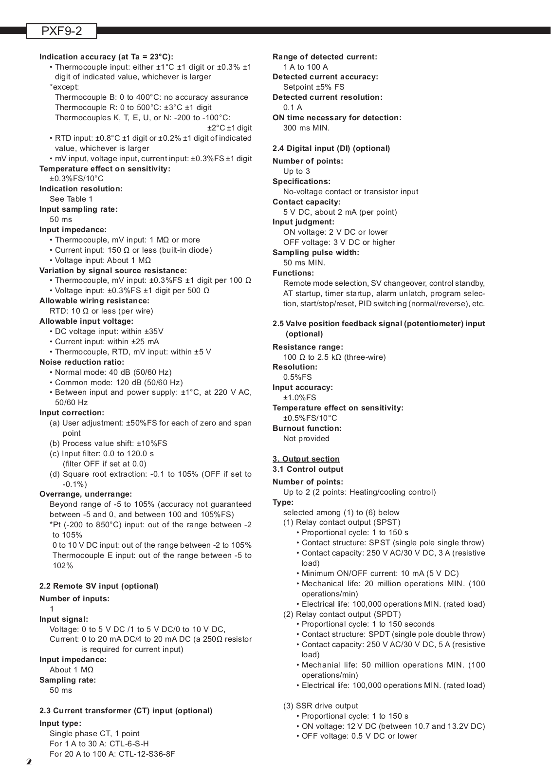
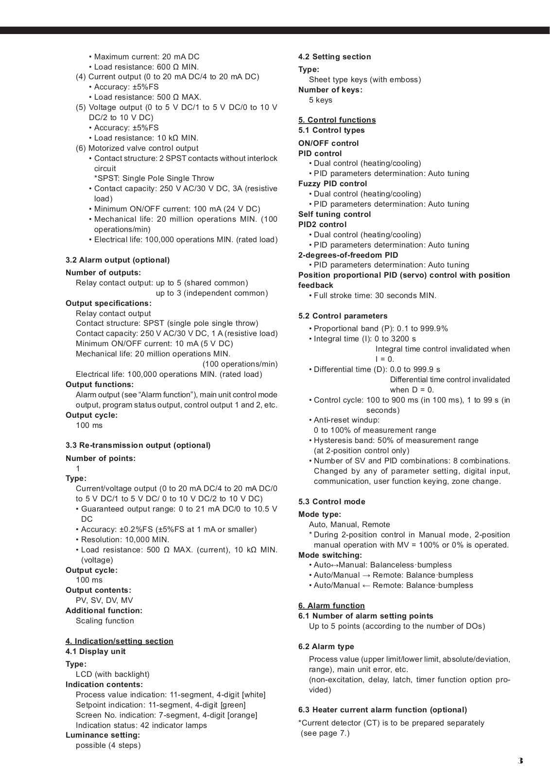
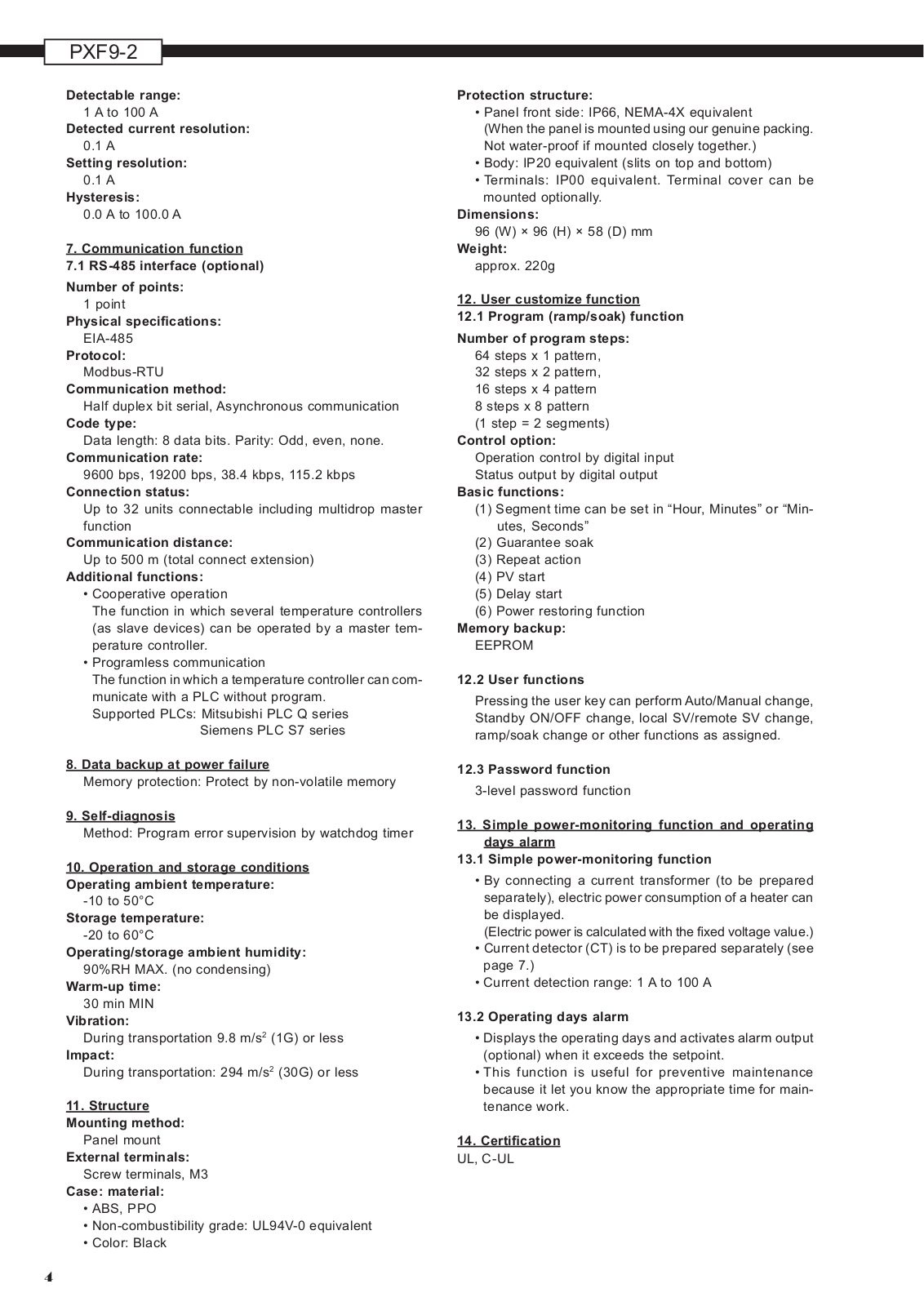
Fuji Electric PXF9 Data sheet
...
Fuji Electric Data sheet
Download
Specifications and Main Features
Frequently Asked Questions
User Manual
Download
Page 1
Page 2
Page 3
Page 4
Page 5
Page 6
Page 7
Page 8
Page 9
Page 10
Page 11
Page 12
Loading...
+
hidden pages
Unhide
You need points to download manuals.
1 point = 1 manual.
You can buy points or you can get point for every manual you upload.
Buy points
Upload your manuals
 Loading...