

Page 1

Operation Manual
Page 2

Record of Revisions
Reference numbers are shown at the bottom left corner on the back cover of each manual.
Printing Date Reference No. Revised Contents
January, 2015 1072NE0 First edition
Page 3
Preface
Thank you for selecting the MONITOUCH V9 series.
For correct setup of the V9 series, you are requested to read through this manual to understand more about the product.
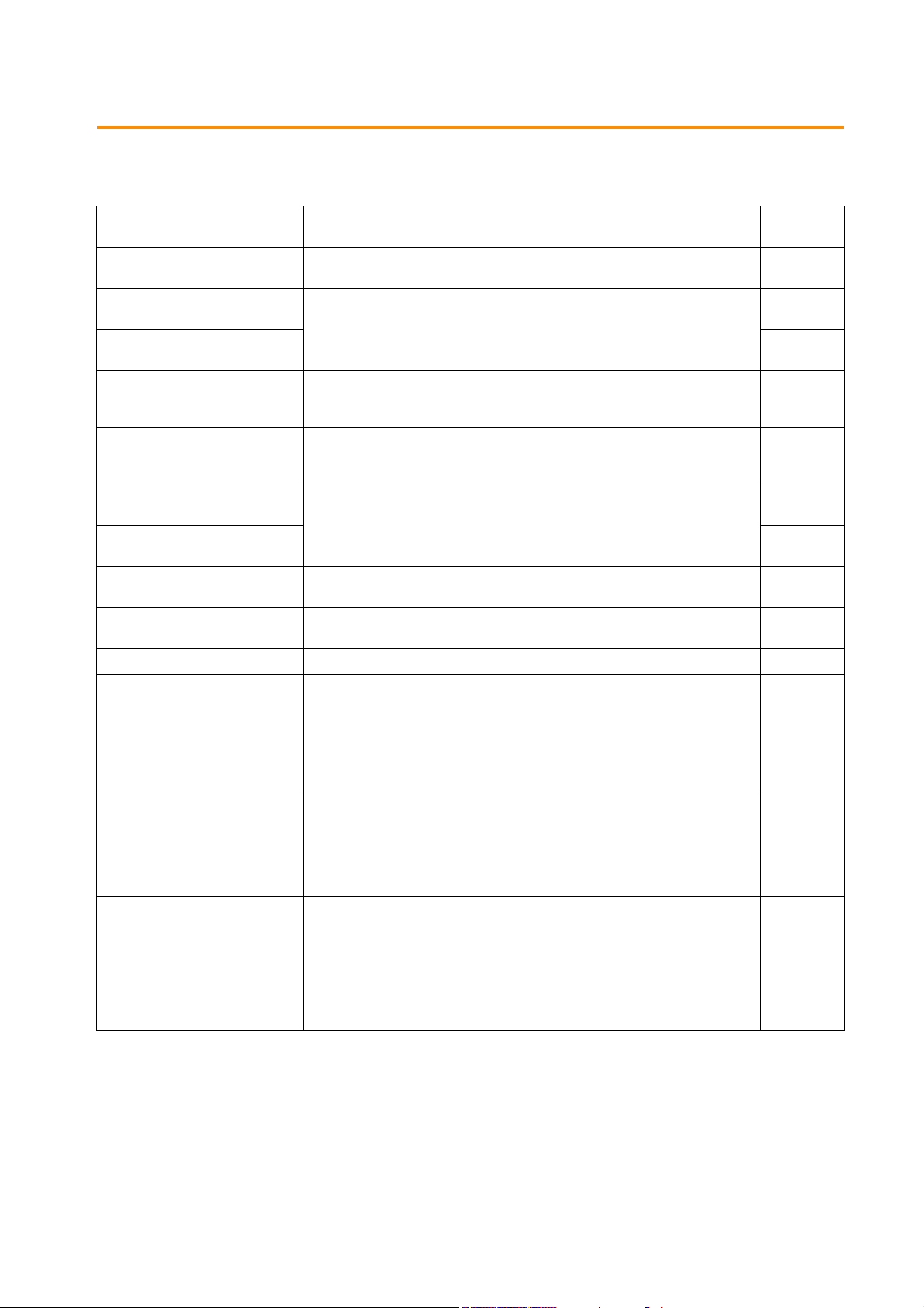
For details on other operating procedures for the V9 series, refer to the following related manuals.
Manual Name Contents
V9 Series
Operation Manual
V9 Series
Reference Manual [1]
V9 Series
Reference Manual [2]
V9 Series
Setup Manual
V9 Series
Troubleshooting/Maintenance
Manual
V9 Series Training Manual
Beginner’s Guide
V9 Series Training Manual Practical
Guide
V9 Series
Macro Reference
V9 Series
Operation Manual
V9 Series Hardware Specifications Explains hardware specifications and precautions when handling the V9 series. 2023NE
V9 Series
Connection Manual [1]
V9 Series
Connection Manual [2]
V9 Series
Connection Manual [3]
Explains the operation of V-SFT version 6, important points when using the editor,
and provides an overview on configuring screens.
Explains the functions and operation of the V9 series. 1065NE
Explains the installation procedure of V-SFT version 6, the creation process of
simple screen programs as well as how to transfer a created screen program using
V-SFT version 6.
Provides an error list and explains the operating procedures for the V9 series. 1068NE
Explains the screen configuration process for the V9 series using V-SFT version 6
with examples.
Provides an overview of macros of V-SFT version 6 and explains macro editor
operations and macro command descriptions in detail.
Explains the configuration of V-SFT version 6, the editing process of each part and
limitations regarding operation in detail.
Explains the connection and communication parameters for the V9 series and
controllers in detail.
Included Makers
ALLEN BRADLEY, Automationdirect, Azbil, Baumuller, BECKHOFF, CHINO,
CIMON, DELTA, DELTA TAU DATA SYSTEMS, EATON Cutler-Hammer,
EMERSON, FANUC, FATEK AUTOMATION, FUFENG, Fuji Electric, Gammaflux,
GE Fanuc, Hitachi, Hitachi Industrial Equipment Systems
Explains the connection and communication parameters for the V9 series and
controllers in detail.
Included Makers
IAI, IDEC, JTEKT, KEYENCE, KOGANEI, KOYO ELECTRONICS, LS,
MITSUBISHI ELECTRIC, MODICON, MOELLER, M-SYSTEM, OMRON,
Oriental Motor, Panasonic, RKC, RS Automation
Explains the connection and communication parameters for the V9 series and
controllers in detail.
Included Makers
SAIA, SAMSUNG, SanRex, SANMEI, SHARP, SHIMADEN, SHINKO TECHNOS,
Siemens, SINFONIA TECHNOLOGY, TECO, Telemecanique, TOHO, TOSHIBA,
TOSHIBA MACHINE, TURCK, UNIPULSE, UNITRONICS, VIGOR, WAGO, XINJE,
YAMAHA, Yaskawa Electric, Yokogawa Electric, MODBUS, Barcode Reader,
Slave Communication Function, Universal Serial Communication
Reference
No.
1072NE
1066NE
1067NE
1069NE
1070NE
1071NE
1072NE
2210NE
2211NE
2212NE
For details on devices including PLCs, inverters, and temperature controllers, refer to the manual for each device.
Page 4

Notes:
1. This manual may not, in whole or in part, be printed or reproduced without the prior written consent of Hakko Electronics
Co., Ltd.
2. The information in this manual is subject to change without prior notice.
3. Windows, Excel, and Word are registered trademarks of Microsoft Corporation in the United States and other countries.
4. All other company names or product names are trademarks or registered trademarks of their respective holders.
5. This manual is intended to give accurate information about MONITOUCH hardware. If you have any questions, please
contact your local distributor.
Page 5
Notes on Safe Usage of MONITOUCH
DANGER
CAUTION
CAUTION
DANGER
CAUTION
In this manual, you will find various notes categorized under the following levels with the signal words “DANGER” and “CAUTION”.
Indicates an imminently hazardous situation which, if not avoided, will result in death or serious injury.
Indicates a potentially hazardous situation which, if not avoided, may result in minor or moderate injury and could
cause property damage.
Note that there is a possibility that items listed with may have serious ramifications.
• Never use the output signal of the V9 series for operations that may threaten human life or damage the system, such as signals
used in case of emergency. Please design the system so that it can cope with a touch switch malfunction. A touch switch
malfunction may result in machine accidents or damage.
• Turn off the power supply when you set up the unit, connect new cables, or perform maintenance or inspections. Otherwise,
electrical shock or damage may occur.
• Never touch any terminals while the power is on. Otherwise, electrical shock may occur.
• You must cover the terminals on the unit before turning the power on and operating the unit. Otherwise, electrical shock may occur.
• The liquid crystal in the LCD panel is a hazardous substance. If the LCD panel is damaged, do not ingest the leaked liquid crystal. If
leaked liquid crystal makes contact with skin or clothing, wash it away with soap and water.
• Never disassemble, recharge, deform by pressure, short-circuit, reverse the polarity of the lithium battery, nor dispose of the lithium
battery in fire. Failure to follow these conditions will lead to explosion or ignition.
• Never use a lithium battery that is deformed, leaking, or shows any other signs of abnormality. Failure to follow these conditions will
lead to explosion or ignition.
• Switches on the screen are operable even when the screen has become dark due to a faulty backlight or when the backlight has
reached the end of its service life. If the screen is dark and hard to see, do not touch the screen. Otherwise, a malfunction may occur
resulting in machine accidents or damage.
• Check the appearance of the unit when it is unpacked. Do not use the unit if any damage or deformation is found. Failure to do so
may lead to fire, damage, or malfunction.
• For use in a facility or as part of a system related to nuclear energy, aerospace, medical, traffic equipment, or mobile installations,
please consult your local distributor.
• Operate (or store) the V9 series under the conditions indicated in this manual and related manuals. Failure to do so could cause fire,
malfunction, physical damage, or deterioration.
• Observe the following environmental restrictions on use and storage of the unit. Otherwise, fire or damage to the unit may result.
- Avoid locations where there is a possibility that water, corrosive gas, flammable gas, solvents, grinding fluids, or cutting oil can
come into contact with the unit.
- Avoid high temperatures, high humidity, and outside weather conditions, such as wind, rain, or direct sunlight.
- Avoid locations where excessive dust, salt, and metallic particles are present.
- Avoid installing the unit in a location where vibrations or physical shocks may be transmitted.
• Equipment must be correctly mounted so that the main terminal of the V9 series will not be touched inadvertently. Otherwise, an
accident or electric shock may occur.
• Tighten the mounting screw on the fixtures of the V9 series to an equal torque of 0.6 N·m.
Excessive tightening may distort the panel surface. Loose mounting screws may cause the unit to fall down, malfunction, or
short-circuit.
• Check periodically that terminal screws on the power supply terminal block and fixtures are firmly tightened. Loosened screws or
nuts may result in fire or malfunction.
• Tighten the terminal screws on the power supply terminal block of the V9 series to an equal torque of 7.1 to 8.8 inch-lbf (0.8 to
1.0 N·m). Improper tightening of screws may result in fire, malfunction, or other serious trouble.
• The V9 series has a glass screen. Do not drop the unit or impart physical shocks to the unit. Otherwise, the screen may be damaged.
• Correctly connect cables to the terminals of the V9 series in accordance with the specified voltage and wattage. Overvoltage,
overwattage, or incorrect cable connection could cause f ire, malfunction, or damage to the unit.
• Always ground the V9 series. The FG terminal must be used exclusively for the V9 series with the level of grounding resistance less
than 100 . Otherwise, you may sustain an electric shock, a f ire may occur, MONITOUCH may not recognize touch operations, and
malfunctions may occur.
• Prevent any conductive particles from entering the V9 series. Failure to do so may lead to fire, damage, or malfunction.
• After wiring is finished, remove the paper used as a dust cover before starting operation of the V9 series. Operation with the dust
cover attached may result in accidents, fire, malfunction, or other trouble.
Page 6

• Do not attempt to repair the V9 series yourself. Contact Hakko Electronics or the designated contractor for repairs.
CAUTION
• Do not repair, disassemble, or modify the V9 series. Hakko Electronics Co., Ltd. is not responsible for any damages resulting from
repair, disassembly, or modification of the unit that was performed by an unauthorized person.
• Do not use sharp-pointed tools to press touch switches. Doing so may damage the display unit.
• Only experts are authorized to set up the unit, connect cables, and perform maintenance and inspection.
• Lithium batteries contain combustible material such as lithium and organic solvents. Mishandling may cause heat, explosion, or
ignition resulting in fire or injury. Read the related manuals carefully and correctly handle the lithium battery as instructed.
• Take safety precautions during operations such as changing settings when the unit is running, forced output, and starting and
stopping the unit. Any misoperations may cause unexpected machine movement, resulting in machine accidents or damage.
• In facilities where the failure of the V9 series could lead to accidents that threaten human life or other serious damage, be sure that
such facilities are equipped with adequate safeguards.
• When disposing of the V9 series, it must be treated as industrial waste.
• Before touching the V9 series, discharge static electricity from your body by touching grounded metal. Excessive static electricity
may cause malfunction or trouble.
• Insert an SD card into MONITOUCH in the same orientation as pictured on the unit. Failure to do so may damage the SD card or the
slot on the unit.
• The SD card access LED flashes red when the SD card is being accessed. Never remove the SD card or turn off power to the unit
while the LED is flashing. Doing so may destroy the data on the SD card. Check that the LED has turned off before removing the SD
card or turning off the power to the unit.
• Be sure to remove the protective sheet that is attached to the touch panel surface at delivery before use. If used with the protective
sheet attached, MONITOUCH may not recognize touch operations or malfunctions may occur.
• When using an analog resistive-film type V9 series unit, do not touch two positions on the screen at the same time. If two or more
positions are pressed at the same time, the switch located between the pressed positions may be activated.
• When using a capacitive V9 series unit, take note of the following cautions.
- Use a Class 2 power supply for a 24-VDC unit. If an unstable power supply is used, MONITOUCH may not recognize touch
operations or malfunctions may occur.
- Capacitive touch panel types support two-point touch operations. If a third point is touched, the touch operation will be
cancelled.
- Capacitive touch panel types are prone to the influence of conductive material. Do not place conductive material such as metals
near the touch panel surface and do not use the panel if it is wet. Otherwise, malfunctions may occur.
[General Notes]
• Never bundle control cables or input/output cables with high-voltage and large-current carrying cables such as power supply cables.
Keep control cables and input/output cables at least 200 mm away from high-voltage and large-current carrying cables. Otherwise,
malfunction may occur due to noise.
• When using the V9 series in an environment where a source of high-frequency noise is present, it is recommended that the FG
shielded cable (communication cable) be grounded at each end. However, when communication is unstable, select between
grounding one or both ends, as permitted by the usage environment.
• Be sure to plug connectors and sockets of the V9 series in the correct orientation. Failure to do so may lead to damage or malfunction.
• If a LAN cable is inserted into the MJ1 or MJ2 connector, the device on the other end may be damaged. Check the connector names
on the unit and insert cables into the correct connectors.
• Do not use thinners for cleaning because it may discolor the V9 series surface. Use commercially available alcohol.
• If a data receive error occurs when the V9 series unit and a counterpart unit (PLC, temperature controller, etc.) are started at the same
time, read the manual of the counterpart unit to correctly resolve the error.
• Avoid discharging static electricity on the mounting panel of the V9 series. Static charge can damage the unit and cause malfunctions.
Discharging static electricity on the mounting panel may cause malfunction to occur due to noise.
• Avoid prolonged display of any fixed pattern. Due to the characteristic of liquid crystal displays, an afterimage may occur. If prolonged
display of a fixed pattern is expected, use the backlight’s auto OFF function.
• The V9 series is identified as a class-A product in industrial environments. In the case of use in a domestic environment, the unit is
likely to cause electromagnetic interference. Preventive measures should thereby be taken appropriately.
[Notes on the LCD]
Note that the following conditions may occur under normal circumstances.
• The response time, brightness, and colors of the V9 series may be affected by the ambient temperature.
• Tiny spots (dark or luminescent) may appear on the display due to the characteristics of liquid crystal.
• There are variations in brightness and color between units.
Page 7

[Notes on Capacitive Touch Panels]
• Touch panel operability may not be optimal if used with dry fingers or skin. In such a case, use a capacitive stylus pen.
• Periodically clean the touch panel surface for optimum touch operations.
When cleaning, take note of the following points.
<When cleaning>
- The panel surface is made of glass. Be sure to clean the surface gently with a cloth or sponge. Otherwise, you may scratch or
damage the glass.
- Take care not to let cleaning detergent to seep into the touch panel unit.
Do not directly apply or spray cleaning detergent on the panel surface.
[Notes on Wireless LAN]
For details regarding supported wireless LAN standards, radio law certif ications, and countries where wireless LAN can be used, refer to
the “V9 Series About Wirelss LAN” manual and the “V9 Series Hardware Specifications” manual provided with the V9 series unit at
delivery.
Page 8

Contents
1Introduction
1.1 Edit Model and Resolution
1.2 Screen Program File Structure
1.2.1 Screen Structural Components .................................................................................................................................................... 1-2
1.2.2 Base Screen/Overlap Display Structure .................................................................................................................................... 1-3
What Is an ID? ...................................................................................................................................................................................... 1-4
Restrictions on identical ID placement ....................................................................................................................... 1-4
Necessity of ID agreement .............................................................................................................................................. 1-4
When using a screen library............................................................................................................................................ 1-5
ID number check.................................................................................................................................................................. 1-6
1.2.3 Screen Capacity .................................................................................................................................................................................. 1-6
2 V-SFT Ver. 6 Configuration and Screen Editing Procedures
2.1 Editing Procedure
Editing Procedure ............................................................................................................................................................................... 2-1
2.2 Starting and Quitting
2.2.1 Starting .................................................................................................................................................................................................. 2-2
Procedure for Creating a New File............................................................................................................................................... 2-2
Opening an Existing File................................................................................................................................................................... 2-4
Edit Model Selection.......................................................................................................................................................................... 2-5
Automatic size adjustment function............................................................................................................................2-6
Procedure for changing the MONITOUCH model ................................................................................................. 2-6
Hardware Settings .............................................................................................................................................................................. 2-7
PLC Property Settings ....................................................................................................................................................................... 2-7
Control Area Settings........................................................................................................................................................................ 2-8
2.2.2 Quitting ................................................................................................................................................................................................. 2-9
2.3 V-SFT Ver. 6 Configuration
2.3.1 Names of Parts ................................................................................................................................................................................. 2-10
2.3.2 Application Menu ............................................................................................................................................................................ 2-11
Language ............................................................................................................................................................................................. 2-11
Text Font .............................................................................................................................................................................................. 2-11
2.3.3 Quick Access Toolbar ..................................................................................................................................................................... 2-12
Customization Procedure .............................................................................................................................................................. 2-12
2.3.4 Ribbon Menu .................................................................................................................................................................................... 2-14
File .......................................................................................................................................................................................................... 2-14
[Property] window.............................................................................................................................................................2-15
[File Information] ...............................................................................................................................................................2-15
[PLC Information]............................................................................................................................................................... 2-16
[General]................................................................................................................................................................................ 2-16
[Edit]........................................................................................................................................................................................2-17
[Transfer]...............................................................................................................................................................................2-17
[Splash Screen] ...................................................................................................................................................................2-18
Home..................................................................................................................................................................................................... 2-18
Parts ....................................................................................................................................................................................................... 2-19
Edit.......................................................................................................................................................................................................... 2-20
View........................................................................................................................................................................................................ 2-21
Screen Setting .................................................................................................................................................................................... 2-21
Transfer................................................................................................................................................................................................. 2-22
System Setting ................................................................................................................................................................................... 2-22
Tool ........................................................................................................................................................................................................ 2-23
Help........................................................................................................................................................................................................ 2-23
Page 9

2.3.5 Item Settings Window ................................................................................................................................................................... 2-24
Other Settings .................................................................................................................................................................................... 2-24
Preview Display.................................................................................................................................................................................. 2-25
Style Settings of Linked Parts....................................................................................................................................................... 2-26
Position adjustment procedure ...................................................................................................................................2-27
[Select from catalogs] ......................................................................................................................................................2-29
[Additional Parts List].......................................................................................................................................................2-29
[Add Parts]............................................................................................................................................................................ 2-30
2.3.6 View Windows .................................................................................................................................................................................. 2-31
Display Method ................................................................................................................................................................................. 2-31
Types of View Windows ................................................................................................................................................................. 2-31
Project list view window..................................................................................................................................................2-31
Catalog view window....................................................................................................................................................... 2-31
Item list view window ......................................................................................................................................................2-32
Function item view window...........................................................................................................................................2-32
Movement Method.......................................................................................................................................................................... 2-33
Docking .................................................................................................................................................................................2-33
2.4 Types of Setting Menus
2.4.1 Menu Types ....................................................................................................................................................................................... 2-34
Pull-down Type.................................................................................................................................................................................. 2-34
Option Button .................................................................................................................................................................................... 2-34
Numerical Data Entry: Box Type.................................................................................................................................................. 2-34
Numerical Data Entry: Underlined Type................................................................................................................................... 2-35
Checkbox.............................................................................................................................................................................................. 2-35
List Type................................................................................................................................................................................................ 2-36
Command Buttons ........................................................................................................................................................................... 2-36
Detailed Settings>>......................................................................................................................................................................... 2-36
2.4.2 Device Memory Settings ............................................................................................................................................................... 2-37
Changing the Specification Method ......................................................................................................................................... 2-37
Device Memory Display Types and Specification Methods............................................................................................. 2-37
Normal display ................................................................................................................................................................... 2-37
Normal display (no input window).............................................................................................................................2-37
Simple display.....................................................................................................................................................................2-38
Types of Device Memory ............................................................................................................................................................... 2-38
PLC device memory..........................................................................................................................................................2-38
Internal device memory ..................................................................................................................................................2-39
Address list........................................................................................................................................................................... 2-39
I/O device memory ...........................................................................................................................................................2-40
2.4.3 Color Settings .................................................................................................................................................................................... 2-41
Color Type Setting............................................................................................................................................................................ 2-41
Color Selection Procedure............................................................................................................................................................. 2-41
[Custom Color] Window................................................................................................................................................................. 2-42
Blinking Setting ................................................................................................................................................................................. 2-43
Blinking setting procedure ............................................................................................................................................2-43
Blinking time setting ........................................................................................................................................................ 2-43
2.5 Configuring the Editing Environment
2.5.1 Changing the Background Color ............................................................................................................................................... 2-44
2.5.2 Grid Display ........................................................................................................................................................................................ 2-46
What Is the “Grid”?........................................................................................................................................................................... 2-46
Detailed Grid Settings..................................................................................................................................................................... 2-46
2.5.3 Changing the Handle Color ......................................................................................................................................................... 2-47
2.5.4 Changing the Margin Color ......................................................................................................................................................... 2-48
2.6 Basic Operations
2.6.1 Screen Switching Procedure ........................................................................................................................................................ 2-49
Switching Screens on the [Home] Menu................................................................................................................................. 2-49
Previous screen/Next screen icons.............................................................................................................................2-49
Jump....................................................................................................................................................................................... 2-49
Selecting from the Screen List..................................................................................................................................................... 2-50
Selecting from the Project List View Window........................................................................................................................ 2-51
2.6.2 Copying Screens .............................................................................................................................................................................. 2-53
Copy Using the Screen List ........................................................................................................................................................... 2-53
Copy Using the Project List View Window.............................................................................................................................. 2-55
2.6.3 Moving Screens ................................................................................................................................................................................ 2-57
Move Using the Screen List .......................................................................................................................................................... 2-57
Move Using Screen Settings......................................................................................................................................................... 2-59
Page 10

2.6.4 Deleting Screens .............................................................................................................................................................................. 2-61
Deleting Using the [Edit] Menu................................................................................................................................................... 2-61
Delete Using the Screen List......................................................................................................................................................... 2-62
Delete Using the Project List View Window........................................................................................................................... 2-63
2.7 Saving Files
2.7.1 Saving by Overwriting ................................................................................................................................................................... 2-65
2.7.2 Saving by Specifying a Name ..................................................................................................................................................... 2-65
2.8 File Comparison
Operating Procedure....................................................................................................................................................................... 2-66
[Comparison] Tab Window ........................................................................................................................................................... 2-67
File comparing menu.......................................................................................................................................................2-68
Procedure for Checking Content Details ................................................................................................................................. 2-68
Checking details in text format ....................................................................................................................................2-68
Checking using screen lists............................................................................................................................................2-69
Procedure for Copying after Comparison............................................................................................................................... 2-70
Using icon checkboxes.................................................................................................................................................... 2-70
Copying by specifying a number ................................................................................................................................2-71
Dragging and dropping between screen lists........................................................................................................2-72
Saving After Copying ...................................................................................................................................................................... 2-75
3Placing Parts
3.1 Parts Types and Limitations
3.1.1 Part Types ............................................................................................................................................................................................. 3-1
Part Files ................................................................................................................................................................................................. 3-2
3.1.2 Limits on Maximum Number of Placeable Parts ................................................................................................................... 3-3
3.2 Placement Procedure
3.2.1 Placing Parts from the Ribbon Menu ........................................................................................................................................ 3-4
Placement Procedure (E.g.: Switch).............................................................................................................................................. 3-4
3.2.2 Placement from the [Catalog] View Window ......................................................................................................................... 3-5
Placement Procedure (E.g.: Switch).............................................................................................................................................. 3-5
3.3 Changing a Part After Placement
3.3.1 Single Parts .......................................................................................................................................................................................... 3-7
Item Settings Window....................................................................................................................................................................... 3-7
Changing the Part Design ............................................................................................................................................................... 3-7
Changing the ON/OFF Design (Only for Switches and Lamps)........................................................................................ 3-9
Changing Coordinates and Size.................................................................................................................................................. 3-10
3.3.2 Linked Parts ....................................................................................................................................................................................... 3-11
What Are “Linked Parts”?............................................................................................................................................................... 3-11
Example of Changing Part Settings (E.g.: Trend Parts)....................................................................................................... 3-11
Adding and deleting parts.............................................................................................................................................3-11
Changing the placement position and size of individual parts......................................................................3-13
Removing links ...................................................................................................................................................................3-14
Linking parts........................................................................................................................................................................3-15
3.4 Placing and Setting Parts
3.4.1 Overlaps .............................................................................................................................................................................................. 3-16
Normal Overlap Display ................................................................................................................................................................. 3-16
Placement procedure.......................................................................................................................................................3-16
Placing items on overlap displays...............................................................................................................................3-17
Multi-overlap (Call-overlap) Display.......................................................................................................................................... 3-22
Placement procedure.......................................................................................................................................................3-22
Overlap parts placement and editing........................................................................................................................3-22
3.4.2 Switches and Lamps ....................................................................................................................................................................... 3-23
Placement procedure.......................................................................................................................................................3-23
Setting method .................................................................................................................................................................. 3-23
3.4.3 Data Display ....................................................................................................................................................................................... 3-24
Numerical Display, Character Display, and Message Display.......................................................................................... 3-24
Placement procedure.......................................................................................................................................................3-24
Setting method .................................................................................................................................................................. 3-24
Page 11

Table Data Display............................................................................................................................................................................ 3-25
Placement procedure.......................................................................................................................................................3-25
Setting method .................................................................................................................................................................. 3-25
Setting and changing data ............................................................................................................................................3-26
Changing the properties of multiple data cells.....................................................................................................3-27
Changing the height and width of cells ...................................................................................................................3-28
Right-click menu................................................................................................................................................................3-28
3.4.4 Entry ...................................................................................................................................................................................................... 3-30
Placement procedure.......................................................................................................................................................3-30
Setting method .................................................................................................................................................................. 3-30
Placing from the [Catalog] view window.................................................................................................................. 3-31
3.4.5 Trend .................................................................................................................................................................................................... 3-32
Placement procedure.......................................................................................................................................................3-32
Setting method .................................................................................................................................................................. 3-32
3.4.6 Alarm .................................................................................................................................................................................................... 3-33
Placement procedure.......................................................................................................................................................3-33
Setting method .................................................................................................................................................................. 3-33
3.4.7 Graph .................................................................................................................................................................................................... 3-34
Placement procedure.......................................................................................................................................................3-34
Setting method .................................................................................................................................................................. 3-34
3.4.8 Time Display/Calendar .................................................................................................................................................................. 3-35
Placement procedure.......................................................................................................................................................3-35
Setting method .................................................................................................................................................................. 3-35
3.4.9 Video/RGB Display, JPEG Display, Network Camera Display, and Remote Desktop Display ............................. 3-36
Placement procedure.......................................................................................................................................................3-36
Setting method .................................................................................................................................................................. 3-36
3.4.10 Graphic ................................................................................................................................................................................................ 3-37
Placement procedure.......................................................................................................................................................3-37
Setting method .................................................................................................................................................................. 3-37
3.4.11 Message and Comment Displays .............................................................................................................................................. 3-38
Placement procedure.......................................................................................................................................................3-38
Setting method .................................................................................................................................................................. 3-38
3.4.12 Recipe, Slider Switch, Data Block Area, Memory Card, and Memo Pad ..................................................................... 3-39
Placement procedure.......................................................................................................................................................3-39
Setting method .................................................................................................................................................................. 3-39
3.5 Registering Function Items
3.5.1 Sound ................................................................................................................................................................................................... 3-40
Registration Procedure................................................................................................................................................................... 3-40
Registering from the [Screen Setting] menu..........................................................................................................3-40
Registering from the [Function Item] view window.............................................................................................3-41
3.5.2 Animation ........................................................................................................................................................................................... 3-42
Registration Procedure................................................................................................................................................................... 3-42
Registering from the [Screen Setting] menu..........................................................................................................3-42
Registering from the [Function Item] view window.............................................................................................3-43
3.5.3 Macro ................................................................................................................................................................................................... 3-44
Registration Procedure................................................................................................................................................................... 3-44
Registering from the [Screen Setting] menu..........................................................................................................3-44
Registering from the [Function Item] view window.............................................................................................3-45
3.5.4 Interval Timer .................................................................................................................................................................................... 3-46
Registration Procedure................................................................................................................................................................... 3-46
Registering from the [Screen Setting] menu..........................................................................................................3-46
Registering from the [Function Item] view window.............................................................................................3-47
3.6 Shape and Text Graphics
3.6.1 Shape .................................................................................................................................................................................................... 3-48
Line ......................................................................................................................................................................................................... 3-48
[Straight Line], [Line (Arrow)], and [Line (Arrows at Both Ends)].....................................................................3-48
[Continuous Line] .............................................................................................................................................................. 3-49
Rectangle ............................................................................................................................................................................................. 3-51
[Rectangle], [Round Chamfering], and [Chamfering]..........................................................................................3-51
Selecting a tile pattern ....................................................................................................................................................3-52
Notes on [Round Chamfering] and [Chamfering] ................................................................................................3-53
Parallelogram...................................................................................................................................................................... 3-54
Polygon .................................................................................................................................................................................3-55
Page 12

Circle ...................................................................................................................................................................................................... 3-57
[Circle]....................................................................................................................................................................................3-57
[Arc] and [Sector]...............................................................................................................................................................3-59
[Ellipse]...................................................................................................................................................................................3-62
[Elliptical Arc]/[Elliptical Sector] ...................................................................................................................................3-63
Paint ....................................................................................................................................................................................................... 3-66
Paint procedure.................................................................................................................................................................. 3-66
Checking the painting position....................................................................................................................................3-67
Paint properties..................................................................................................................................................................3-68
Dot.......................................................................................................................................................................................................... 3-69
Drawing method................................................................................................................................................................3-69
Scale....................................................................................................................................................................................................... 3-70
[Bar Graph Scale] ...............................................................................................................................................................3-70
[Pie Graph Scale] ............................................................................................................................................................................... 3-71
Drawing method................................................................................................................................................................3-71
[Trend Graph Scale]..........................................................................................................................................................3-73
Library.................................................................................................................................................................................................... 3-74
[Pattern].................................................................................................................................................................................3-74
Placing a pattern................................................................................................................................................................3-74
Placing multiple patterns consecutively...................................................................................................................3-75
Graphic library (GLIB)....................................................................................................................................................... 3-76
Screen library (SLIB)..........................................................................................................................................................3-78
Item view window .............................................................................................................................................................3-79
3.6.2 Text ........................................................................................................................................................................................................ 3-80
Text and Multi Text .......................................................................................................................................................................... 3-80
Placement procedure.......................................................................................................................................................3-80
Item view window .............................................................................................................................................................3-81
3.6.3 Pattern ................................................................................................................................................................................................. 3-83
Picture ................................................................................................................................................................................................... 3-83
Placement procedure.......................................................................................................................................................3-83
Item view window .............................................................................................................................................................3-84
Pattern................................................................................................................................................................................................... 3-85
Placement procedure.......................................................................................................................................................3-85
Dialog box displayed during image import ............................................................................................................3-87
Item view window .............................................................................................................................................................3-87
Parts ....................................................................................................................................................................................................... 3-88
Applicable items ................................................................................................................................................................ 3-88
Placement procedure.......................................................................................................................................................3-88
3.6.4 Changing the Properties of Drawing Parts ............................................................................................................................ 3-93
Displaying the Item View Window............................................................................................................................................. 3-93
Display by clicking............................................................................................................................................................. 3-93
Display by double-clicking............................................................................................................................................. 3-93
Examples of Item View Windows................................................................................................................................................ 3-94
Straight line.......................................................................................................................................................................... 3-94
Rectangle..............................................................................................................................................................................3-94
Text..........................................................................................................................................................................................3-94
3.7 Component Parts
3.7.1 Overview ............................................................................................................................................................................................. 3-95
3.7.2 Placement Procedure ..................................................................................................................................................................... 3-95
3.7.3 Settings ................................................................................................................................................................................................ 3-96
4 Useful Editing and View Menus
4.1 Edit Menu
4.1.1 Edit .......................................................................................................................................................................................................... 4-1
Multi-copy ............................................................................................................................................................................................. 4-1
Setting example ................................................................................................................................................................... 4-3
Selection Pasting................................................................................................................................................................................. 4-4
4.1.2 Place ........................................................................................................................................................................................................ 4-5
Place (E.g. Left End)............................................................................................................................................................................ 4-6
Arrangement (E.g.: Vertical Align) ................................................................................................................................................ 4-7
4.1.3 Size .......................................................................................................................................................................................................... 4-8
Setting Example................................................................................................................................................................................... 4-8
4.1.4 Style ........................................................................................................................................................................................................ 4-9
Arrow Type ............................................................................................................................................................................................ 4-9
Line Type................................................................................................................................................................................................ 4-9
Frame Type.......................................................................................................................................................................................... 4-10
Page 13

4.1.5 Modify Parts ...................................................................................................................................................................................... 4-11
4.1.6 Selection Environment Setting ................................................................................................................................................... 4-14
4.1.7 Select/Delete ..................................................................................................................................................................................... 4-14
4.1.8 Right-click Menu .............................................................................................................................................................................. 4-15
4.2 View Menu
4.2.1 Display Change ................................................................................................................................................................................. 4-18
4.2.2 View ...................................................................................................................................................................................................... 4-18
4.2.3 Grid ........................................................................................................................................................................................................ 4-26
4.2.4 Display Environment ...................................................................................................................................................................... 4-28
4.2.5 Zoom .................................................................................................................................................................................................... 4-34
Change to Switch / Change to Lamp........................................................................................................................................ 4-11
Change to Multi-Text ...................................................................................................................................................................... 4-12
Settings................................................................................................................................................................................................. 4-14
Menu Display When No Items are Selected........................................................................................................................... 4-15
Menu Display When Items are Selected.................................................................................................................................. 4-15
Batch Change ..................................................................................................................................................................................... 4-16
Setting method .................................................................................................................................................................. 4-16
Detail Setting...................................................................................................................................................................................... 4-17
Setting method .................................................................................................................................................................. 4-17
[Project View] Window ................................................................................................................................................................... 4-18
Example: Hardware Setting ........................................................................................................................................... 4-19
Example: Screen .................................................................................................................................................................4-19
Catalog View Window..................................................................................................................................................................... 4-20
Item List ................................................................................................................................................................................................ 4-21
Icon menu.............................................................................................................................................................................4-21
Operation Method ........................................................................................................................................................................... 4-22
Changing text...................................................................................................................................................................... 4-22
Changing Device Memory............................................................................................................................................................. 4-22
Changing Coordinates.................................................................................................................................................................... 4-23
Displaying the Item Settings Window ...................................................................................................................................... 4-23
[Function Item] View Window...................................................................................................................................................... 4-24
Operation method ............................................................................................................................................................4-25
[Grid Setting] Window .................................................................................................................................................................... 4-26
[Grid] tab...............................................................................................................................................................................4-26
[Initial Frame Display] tab ..............................................................................................................................................4-28
Display Environment Settings...................................................................................................................................................... 4-29
[Display] tab.........................................................................................................................................................................4-29
[Others] Tab ........................................................................................................................................................................................ 4-32
4.2.6 Redraw ................................................................................................................................................................................................. 4-34
4.3 Screen Setting Menu
4.3.1 [Screen Setting] Window .............................................................................................................................................................. 4-35
[Main] Tab............................................................................................................................................................................................ 4-35
[Scroll] Tab........................................................................................................................................................................................... 4-35
[Entry] Tab............................................................................................................................................................................................ 4-35
[Others] Tab ........................................................................................................................................................................................ 4-36
[PLC Device Transfer] Tab.............................................................................................................................................................. 4-36
[Unhide] Tab ....................................................................................................................................................................................... 4-37
5Tools
5.1 Tool Menu
5.2 Error Check
5.2.1 Display Method .................................................................................................................................................................................. 5-2
5.2.2 Error Types ........................................................................................................................................................................................... 5-2
5.2.3 Icon Menu ............................................................................................................................................................................................ 5-2
5.3 List of Memory Use
5.3.1 Display Method .................................................................................................................................................................................. 5-3
Page 14

5.3.2 Checking Registration Details of Registered Items .............................................................................................................. 5-4
5.3.3 3D Bitmap Area List .......................................................................................................................................................................... 5-5
5.4 Search
5.4.1 Device Memory Addresses ............................................................................................................................................................ 5-7
5.4.2 Tag Usage ........................................................................................................................................................................................... 5-11
5.4.3 Text ........................................................................................................................................................................................................ 5-15
5.4.4 Windows Font ................................................................................................................................................................................... 5-22
Overview................................................................................................................................................................................................. 5-5
Parts ......................................................................................................................................................................................................... 5-5
Display Method ................................................................................................................................................................................... 5-5
Checking Locations of Use.............................................................................................................................................................. 5-6
Checking Part Sizes............................................................................................................................................................................ 5-6
Notes ....................................................................................................................................................................................................... 5-6
Search Method .................................................................................................................................................................................... 5-7
Searching using cross-referencing ............................................................................................................................... 5-7
Searching without using cross-referencing...............................................................................................................5-9
[View] Menu........................................................................................................................................................................................ 5-10
Displaying the [Tag Use] View Window................................................................................................................................... 5-11
Tag Use View Window .................................................................................................................................................................... 5-12
Operation Method ........................................................................................................................................................................... 5-13
To search for the position where a tag is used......................................................................................................5-13
To check the status of use .............................................................................................................................................5-14
Operating Procedure....................................................................................................................................................................... 5-19
Search ....................................................................................................................................................................................5-19
Replacement........................................................................................................................................................................5-21
5.4.5 Macro Command ............................................................................................................................................................................. 5-23
Display Method ................................................................................................................................................................................. 5-23
Operating Procedure....................................................................................................................................................................... 5-25
5.4.6 Cross-reference ................................................................................................................................................................................ 5-27
Display Method ................................................................................................................................................................................. 5-27
Operating Procedure....................................................................................................................................................................... 5-28
5.5 Batch Change
5.5.1 Device Memory Addresses .......................................................................................................................................................... 5-30
Changing Device Memory of Selected Items Only.............................................................................................................. 5-32
5.5.2 Windows Font ................................................................................................................................................................................... 5-33
5.5.3 Multi Language ................................................................................................................................................................................ 5-34
Multi Language Batch Change .................................................................................................................................................... 5-34
Multi Language Batch Copy ......................................................................................................................................................... 5-38
Rearrange Language Order .......................................................................................................................................................... 5-42
5.5.4 Change Order INC ........................................................................................................................................................................... 5-44
Target Items........................................................................................................................................................................................ 5-45
Setting Items....................................................................................................................................................................................... 5-46
Order Change Procedure............................................................................................................................................................... 5-47
5.5.5 Screen Library ................................................................................................................................................................................... 5-52
Setting Method.................................................................................................................................................................................. 5-52
5.5.6 Fix 3D Parts Frame ........................................................................................................................................................................... 5-54
Setting Method.................................................................................................................................................................................. 5-54
Operating procedure ....................................................................................................................................................... 5-30
Option settings................................................................................................................................................................... 5-31
Operating procedure .......................................................................................................................................................5-32
Option settings...................................................................................................................................................................5-33
Location of settings..........................................................................................................................................................5-34
Setting items .......................................................................................................................................................................5-35
Setting procedure ............................................................................................................................................................. 5-37
Location of settings..........................................................................................................................................................5-38
Setting items .......................................................................................................................................................................5-39
Setting procedure ............................................................................................................................................................. 5-41
Location of settings..........................................................................................................................................................5-42
Setting items .......................................................................................................................................................................5-42
Setting procedure ............................................................................................................................................................. 5-43
[Change Order INC] window.........................................................................................................................................5-46
[Automatic Allocation]: [Coordinate Order]............................................................................................................5-47
[Automatic Allocation]: [Placement Order] .............................................................................................................5-49
[Specify with Mouse]........................................................................................................................................................5-50
Page 15

5.6 Others
5.6.1 Screen Image ..................................................................................................................................................................................... 5-56
Save as Pattern Image..................................................................................................................................................................... 5-56
Copy to Clipboard ............................................................................................................................................................................ 5-58
Save in Image File............................................................................................................................................................................. 5-60
5.6.2 Convert to Rich Text Format ....................................................................................................................................................... 5-62
5.6.3 DXF File Convert ............................................................................................................................................................................... 5-64
Operating Procedure....................................................................................................................................................................... 5-64
6 Registration Items
6.1 Overview
6.1.1 Outline of Registration Items ........................................................................................................................................................ 6-1
6.1.2 Types of Registration Items ........................................................................................................................................................... 6-2
6.2 Screen
6.2.1 Calling a Screen .................................................................................................................................................................................. 6-3
Operation method ............................................................................................................................................................5-56
Operation method ............................................................................................................................................................5-58
Pasting the copied image in other application software...................................................................................5-59
Saving format......................................................................................................................................................................5-60
Saving target .......................................................................................................................................................................5-60
Operation method ............................................................................................................................................................5-60
[Detail Setting] options ...................................................................................................................................................5-65
6.2.2 Editing Procedure .............................................................................................................................................................................. 6-3
6.3 Message
6.3.1 Message Structure ............................................................................................................................................................................ 6-4
Relationship between Group Numbers and Absolute Addresses ................................................................................... 6-4
6.3.2 Calling a Message ............................................................................................................................................................................. 6-5
Message Edit Window ...................................................................................................................................................................... 6-5
6.3.3 Message Editing ................................................................................................................................................................................. 6-6
Text Properties (Windows Font).................................................................................................................................................... 6-6
Copying and Pasting Messages .................................................................................................................................................... 6-7
Deleting Messages............................................................................................................................................................................. 6-7
Message Search and Replacement.............................................................................................................................................. 6-8
6.3.4 Display Environment of the Message Editing Window ....................................................................................................... 6-9
6.4 Overlap Library
6.4.1 Overlap Library Structure ............................................................................................................................................................. 6-10
6.4.2 Calling an Overlap Library ............................................................................................................................................................ 6-10
6.4.3 Editing an Overlap Library ............................................................................................................................................................ 6-11
Placing an Overlap ........................................................................................................................................................................... 6-11
Item Placement on Overlap Display.......................................................................................................................................... 6-12
6.4.4 Other Settings ................................................................................................................................................................................... 6-14
Macro Settings................................................................................................................................................................................... 6-15
Search ...................................................................................................................................................................................... 6-8
Replacement.......................................................................................................................................................................... 6-8
Method 1: Select the overlap........................................................................................................................................6-12
Method 2: Display the [Overlap Edit] window. ......................................................................................................6-12
Macro setting commands ..............................................................................................................................................6-15
Macro editing and deleting...........................................................................................................................................6-15
6.5 Screen Library
6.5.1 Outline of Screen Library .............................................................................................................................................................. 6-16
Saving of Screen Memory Space................................................................................................................................................ 6-16
Screen Parts Management Through Screen Library............................................................................................................ 6-16
6.5.2 Screen Library Structure ................................................................................................................................................................ 6-17
Page 16

6.5.3 Calling a Screen Library ................................................................................................................................................................. 6-17
6.5.4 Screen Library Editing .................................................................................................................................................................... 6-18
Offset Position Setting.................................................................................................................................................................... 6-18
Placing a Screen Library ................................................................................................................................................................. 6-19
Changing Numbers After Screen Library Placement .......................................................................................................... 6-19
Screen Library Device Memory Specification......................................................................................................................... 6-20
6.5.5 Screen Library Environment Settings ....................................................................................................................................... 6-21
6.6 Graphic Library
6.6.1 Graphic Library Structure .............................................................................................................................................................. 6-23
6.6.2 Calling the Graphic Library .......................................................................................................................................................... 6-23
6.6.3 Graphic Library Editing .................................................................................................................................................................. 6-24
Offset Position Setting.................................................................................................................................................................... 6-24
Parameter Settings........................................................................................................................................................................... 6-25
Data Display........................................................................................................................................................................................ 6-31
6.6.4 Graphic Library Environment Settings ..................................................................................................................................... 6-33
Changing an offset position..........................................................................................................................................6-18
[Display] area....................................................................................................................................................................... 6-20
[Base Screen Dsp.] ([Others] tab).................................................................................................................................6-21
[Background] ([Others] tab)........................................................................................................................................... 6-22
Outline of offset position ...............................................................................................................................................6-24
Changing an offset position..........................................................................................................................................6-25
Outline of parameters...................................................................................................................................................... 6-25
Parameter setting procedure........................................................................................................................................6-26
[Parameter] area ................................................................................................................................................................ 6-26
Parameter setting items..................................................................................................................................................6-29
Outline of data display in the graphic library.........................................................................................................6-31
Data display placement procedure ............................................................................................................................6-31
Data display setting procedure....................................................................................................................................6-32
6.7 Multi-language
6.8 Macro Block
6.8.1 Macro Block Structure ................................................................................................................................................................... 6-33
6.8.2 Calling a Macro Block .................................................................................................................................................................... 6-33
6.8.3 Macro Block Editing ........................................................................................................................................................................ 6-33
6.9 Tag Database
6.10 Data Sheet
6.10.1 Data Sheet Structure ...................................................................................................................................................................... 6-34
6.10.2 Calling a Data Sheet ....................................................................................................................................................................... 6-34
6.10.3 Data Sheet Editing ........................................................................................................................................................................... 6-35
Data Sheet Setting............................................................................................................................................................................ 6-35
Graphics................................................................................................................................................................................................ 6-35
6.11 Comment
6.11.1 Comment Structure ........................................................................................................................................................................ 6-38
Limitations on Comments ............................................................................................................................................................. 6-38
6.11.2 Calling a Comment ......................................................................................................................................................................... 6-38
[Convert to Extended Data Sheet]: Unselected .....................................................................................................6-36
[Convert to Extended Data Sheet]: Selected...........................................................................................................6-37
6.11.3 Editing a Comment ......................................................................................................................................................................... 6-39
Entering a Comment ....................................................................................................................................................................... 6-39
Text Properties................................................................................................................................................................................... 6-39
Deleting a Comment ....................................................................................................................................................................... 6-40
Comment Import and Export....................................................................................................................................................... 6-41
Comment import and export procedure..................................................................................................................6-41
About TXT format..............................................................................................................................................................6-41
About CSV format .............................................................................................................................................................6-42
6.11.4 [Page] Menu ...................................................................................................................................................................................... 6-43
Page 17

6.12 Animation
6.12.1 Animation Function Structure .................................................................................................................................................... 6-44
6.12.2 Calling an Animation ...................................................................................................................................................................... 6-44
6.12.3 Animation Editing ............................................................................................................................................................................ 6-45
6.12.4 Frame Editing .................................................................................................................................................................................... 6-47
6.13 Pattern
6.13.1 Pattern Structure .............................................................................................................................................................................. 6-48
6.13.2 Calling a Pattern ............................................................................................................................................................................... 6-48
6.13.3 Pattern Editing .................................................................................................................................................................................. 6-49
6.13.4 Transforming Patterns ................................................................................................................................................................... 6-53
6.13.5 Image File Import and Saving ..................................................................................................................................................... 6-55
6.13.6 Pattern Environment Settings ..................................................................................................................................................... 6-58
6.13.7 Placing a Pattern .............................................................................................................................................................................. 6-59
Frame Structure................................................................................................................................................................................. 6-47
Frame Editing ..................................................................................................................................................................................... 6-47
Eraser ..................................................................................................................................................................................................... 6-49
Line ......................................................................................................................................................................................................... 6-50
Rectangle ............................................................................................................................................................................................. 6-50
Text......................................................................................................................................................................................................... 6-51
Paint ....................................................................................................................................................................................................... 6-52
Box Select Area.................................................................................................................................................................................. 6-52
Using [Box Select Area]...................................................................................................................................................6-52
[Rotate Graphic] (rotate 90 to the left)....................................................................................................................6-53
[Mirror Horizontal] ............................................................................................................................................................6-53
[Mirror Vertical].................................................................................................................................................................. 6-53
[Change Size] ...................................................................................................................................................................... 6-54
[Transparent Color Setting] ...........................................................................................................................................6-54
Importing Image Files ..................................................................................................................................................................... 6-55
Window displayed during image import .................................................................................................................6-56
Saving Image Files............................................................................................................................................................................ 6-57
Display Environment Settings...................................................................................................................................................... 6-58
Pattern number setting on multi-language screens............................................................................................6-59
6.14 Data Block
6.14.1 Data Block Structure ....................................................................................................................................................................... 6-60
6.14.2 Calling a Data Block ........................................................................................................................................................................ 6-60
6.14.3 Data Block Editing ........................................................................................................................................................................... 6-61
6.15 Page Block
6.15.1 Page Block Structure ...................................................................................................................................................................... 6-64
6.15.2 Calling a Page Block ....................................................................................................................................................................... 6-64
6.15.3 Page Block Editing ........................................................................................................................................................................... 6-65
6.16 Direct Block
6.16.1 Direct Block Structure .................................................................................................................................................................... 6-66
6.16.2 Calling a Direct Block ..................................................................................................................................................................... 6-66
6.16.3 Direct Block Editing ......................................................................................................................................................................... 6-67
Placing Parts ....................................................................................................................................................................................... 6-61
Placement procedure.......................................................................................................................................................6-61
Offset Position Setting.................................................................................................................................................................... 6-61
Changing an offset position..........................................................................................................................................6-61
Data Block Environment Settings ............................................................................................................................................... 6-62
[Base Screen Dsp.] ([Others] tab).................................................................................................................................6-62
[Background] ([Others] tab)........................................................................................................................................... 6-63
Page 18

6.17 Tile
6.17.1 Tile Structure ..................................................................................................................................................................................... 6-69
6.17.2 Calling a Tile ...................................................................................................................................................................................... 6-69
6.17.3 Tile Editing .......................................................................................................................................................................................... 6-70
7Transfer
7.1 Overview
7.1.1 Transfer Methods .............................................................................................................................................................................. 7-1
Using a Communication Cable...................................................................................................................................................... 7-1
Using a Storage Device .................................................................................................................................................................... 7-2
7.1.2 Types of Data to Transfer ............................................................................................................................................................... 7-3
Transfer Data List ................................................................................................................................................................................ 7-3
7.2 Preparation for Transfer
7.2.1 Preparation for MONITOUCH ....................................................................................................................................................... 7-4
New MONITOUCH ............................................................................................................................................................................. 7-4
Existing MONITOUCH ....................................................................................................................................................................... 7-5
Preparation of Peripheral Equipment ......................................................................................................................................... 7-6
USB (USB mini-B port)....................................................................................................................................................... 7-1
Ethernet (LAN port) ............................................................................................................................................................7-1
V-CP (serial port) ................................................................................................................................................................. 7-2
SD card .................................................................................................................................................................................... 7-2
USB flash drive......................................................................................................................................................................7-2
When transferring via USB or V-CP:............................................................................................................................. 7-4
When transferring via Ethernet or a storage device:.............................................................................................7-4
Via USB .................................................................................................................................................................................... 7-6
Via Ethernet ........................................................................................................................................................................... 7-6
Via V-CP ..................................................................................................................................................................................7-6
Via a storage device ........................................................................................................................................................... 7-6
7.3 USB Transfer
7.3.1 Installing the USB Driver ................................................................................................................................................................. 7-7
For Windows Vista/7/8/8.1 ............................................................................................................................................................. 7-7
For Windows XP .................................................................................................................................................................................. 7-7
When USB driver installation fails ................................................................................................................................................ 7-8
Confirming Installation of the USB Driver................................................................................................................................. 7-9
7.3.2 Transfer ................................................................................................................................................................................................ 7-10
Download............................................................................................................................................................................................. 7-10
Upload................................................................................................................................................................................................... 7-12
File Comparing................................................................................................................................................................................... 7-13
7.4 Ethernet Transfer
7.4.1 IP Address Settings ......................................................................................................................................................................... 7-14
Configuring New Units ................................................................................................................................................................... 7-14
Configuring Existing Units............................................................................................................................................................. 7-15
Network Test ...................................................................................................................................................................................... 7-18
7.4.2 Transfer ................................................................................................................................................................................................ 7-21
Download............................................................................................................................................................................................. 7-21
Upload................................................................................................................................................................................................... 7-23
File Comparing................................................................................................................................................................................... 7-24
7.5 V-CP Transfer
Download............................................................................................................................................................................................. 7-25
Upload................................................................................................................................................................................................... 7-27
File Comparing................................................................................................................................................................................... 7-28
V9 Advanced .......................................................................................................................................................................7-15
V9 Standard / Lite.............................................................................................................................................................. 7-16
Testing in Local Mode on the V9 Series Unit .........................................................................................................7-18
Testing using the PING command on the computer ..........................................................................................7-20
7.6 Transfer via Storage
Transfer Procedure for Storage Device V9 Series Unit................................................................................................. 7-29
Transfer procedure for editor storage device (using storage manager)................................................7-29
Transfer procedure for storage device V9 series unit ...................................................................................7-32
Page 19

Transfer Procedure for V9 Series Unit Storage Device................................................................................................. 7-34
Transfer procedure for V9 series unit storage device ...................................................................................7-34
Converting a Storage Device File V9 File (using storage manager).........................................................7-36
Procedure for V9 Series Unit Storage Device Comparison ........................................................................................ 7-38
7.7 Selective Transfer
Operation Example........................................................................................................................................................................... 7-39
Setting Items....................................................................................................................................................................................... 7-40
Setting Procedure............................................................................................................................................................................. 7-42
Administrator settings .....................................................................................................................................................7-42
Settings for users 1 to 4..................................................................................................................................................7-43
PC <- V9 series unit transfer......................................................................................................................................... 7-44
Notes ..................................................................................................................................................................................................... 7-44
7.8 Message/Comment Transfer
Operation Example........................................................................................................................................................................... 7-45
Target Items........................................................................................................................................................................................ 7-46
Location of Settings......................................................................................................................................................................... 7-46
Setting Procedure............................................................................................................................................................................. 7-46
Message................................................................................................................................................................................7-46
Comment..............................................................................................................................................................................7-48
Notes ..................................................................................................................................................................................................... 7-50
8Simulation
8.1 Simulator
8.1.1 Overview ............................................................................................................................................................................................... 8-1
8.1.2 Operating Procedure ........................................................................................................................................................................ 8-2
8.1.3 Establishing a Connection Between the Computer and V9 Series Unit ....................................................................... 8-3
Via USB.................................................................................................................................................................................................... 8-3
Via Ethernet........................................................................................................................................................................................... 8-3
Via V-CP.................................................................................................................................................................................................. 8-3
8.1.4 Screen Program and Simulator Program Transfer ................................................................................................................ 8-4
Screen Program Transfer ................................................................................................................................................................. 8-4
V9 Series Unit Settings ..................................................................................................................................................................... 8-5
8.1.5 Starting and Quitting the Simulator ........................................................................................................................................... 8-7
Startup..................................................................................................................................................................................................... 8-7
Quitting................................................................................................................................................................................................... 8-7
8.1.6 Starting and Stopping Communication .................................................................................................................................... 8-8
Starting Communication.................................................................................................................................................................. 8-8
Stopping Communication ............................................................................................................................................................... 8-8
Communication Settings ................................................................................................................................................................. 8-9
Via USB ....................................................................................................................................................................................8-9
Via Ethernet ........................................................................................................................................................................... 8-9
Via serial communication...............................................................................................................................................8-10
8.1.7 Structure of the [Simulator] Window ....................................................................................................................................... 8-11
Menu Bar.............................................................................................................................................................................................. 8-12
File ...........................................................................................................................................................................................8-12
Edit ..........................................................................................................................................................................................8-12
Communication..................................................................................................................................................................8-13
View ........................................................................................................................................................................................8-13
Window .................................................................................................................................................................................8-13
Help.........................................................................................................................................................................................8-13
Icon Menu............................................................................................................................................................................................ 8-14
Sheet Structure .................................................................................................................................................................................. 8-15
8.1.8 Operation Method .......................................................................................................................................................................... 8-16
Changing Values (Word Address) .............................................................................................................................................. 8-16
Adding a New Address................................................................................................................................................................... 8-17
Display Device Memory.................................................................................................................................................................. 8-18
8.1.9 Test Example ...................................................................................................................................................................................... 8-19
Testing Bit Device Memory........................................................................................................................................................... 8-19
V9 series unit simulator.............................................................................................................................................8-19
Simulator V9 series unit ............................................................................................................................................8-20
Testing Word Device Memory..................................................................................................................................................... 8-21
8.1.10 Error List .............................................................................................................................................................................................. 8-22
Page 20

8.2 Emulator
8.2.1 Overview ............................................................................................................................................................................................. 8-23
8.2.2 Operating Procedure ...................................................................................................................................................................... 8-24
8.2.3 Structure of the [Emulator] Window ........................................................................................................................................ 8-26
9Printing
9.1 Overview
9.1.1 Compatible Printers .......................................................................................................................................................................... 9-1
9.2 Printing
9.2.1 Operating Procedure ........................................................................................................................................................................ 9-2
9.2.2 Print Settings ....................................................................................................................................................................................... 9-2
Starting and Quitting ...................................................................................................................................................................... 8-24
Startup ...................................................................................................................................................................................8-24
Quitting .................................................................................................................................................................................8-24
Operation Example........................................................................................................................................................................... 8-25
Menu Bar.............................................................................................................................................................................................. 8-26
File ...........................................................................................................................................................................................8-26
View ........................................................................................................................................................................................8-26
Icon Menu............................................................................................................................................................................................ 8-26
Output Range....................................................................................................................................................................................... 9-3
[Current Screen] ................................................................................................................................................................... 9-3
[All]............................................................................................................................................................................................ 9-3
[Select] .....................................................................................................................................................................................9-3
Print Format .......................................................................................................................................................................................... 9-4
Page Settings........................................................................................................................................................................................ 9-5
9.3 Print Preview
9.3.1 Operating Procedure ........................................................................................................................................................................ 9-6
9.4 Print Current Window
9.4.1 Operating Procedure ........................................................................................................................................................................ 9-6
9.5 Example of Printing
Screen Output...................................................................................................................................................................................... 9-6
List Output............................................................................................................................................................................................. 9-7
Table Print.............................................................................................................................................................................................. 9-8
Use Cross-reference........................................................................................................................................................................... 9-8
10 Fonts
10.1 Font Types
System Fonts ...................................................................................................................................................................................... 10-1
Windows Fonts .................................................................................................................................................................................. 10-1
Supported Language List............................................................................................................................................................... 10-2
Checking Fonts in Local Mode .................................................................................................................................................... 10-3
Font Size............................................................................................................................................................................................... 10-4
Memory Sizes of Fonts ................................................................................................................................................................... 10-4
System settings .................................................................................................................................................................... 9-7
List of memory use .............................................................................................................................................................9-8
For screens............................................................................................................................................................................. 9-8
For screen library................................................................................................................................................................. 9-8
Bitmap font..........................................................................................................................................................................10-4
10.2 Setting Fonts
10.2.1 Font Settings ..................................................................................................................................................................................... 10-5
Fonts ...................................................................................................................................................................................................... 10-5
Transfer Font Settings..................................................................................................................................................................... 10-6
Import and Export ............................................................................................................................................................................ 10-7
Page 21

10.3 Entering Multiple Languages
Example: Entering “Chinese (simplified)” Text in a English OS........................................................................................ 10-8
Adding input method editors (IMEs).........................................................................................................................10-8
Text entry procedure..................................................................................................................................................... 10-10
10.4 Windows Font
10.4.1 Limitations ....................................................................................................................................................................................... 10-11
10.4.2 Setting Items .................................................................................................................................................................................. 10-12
10.4.3 Setting Procedure ......................................................................................................................................................................... 10-13
Character Properties..................................................................................................................................................................... 10-13
In Message Editing........................................................................................................................................................................ 10-14
Font Registration............................................................................................................................................................................ 10-15
Font registration file...................................................................................................................................................... 10-16
[Windows Font Registration] window .................................................................................................................... 10-16
10.4.4 [Windows Font List] Window ................................................................................................................................................... 10-17
Window Location........................................................................................................................................................................... 10-17
10.4.5 Change All Windows Fonts ....................................................................................................................................................... 10-17
Procedure.......................................................................................................................................................................................... 10-17
10.4.6 Windows Fonts for Language Selection .............................................................................................................................. 10-19
Conditions for Language Selection Using Windows Fonts ........................................................................................... 10-19
Multi-Language Editing Using Windows Fonts.................................................................................................................. 10-19
10.4.7 Windows Fonts Not Installed on Your Computer Exist in a Screen Program ....................................................... 10-20
When Opening a File.................................................................................................................................................................... 10-20
When Error Checking is Performed ........................................................................................................................................ 10-20
When Viewing Text Properties ................................................................................................................................................. 10-20
When Enlarging/Reducing ......................................................................................................................................................... 10-21
[Windows Font List] Window .................................................................................................................................................... 10-21
[Windows Font Registration] Window................................................................................................................................... 10-21
11 Parts Editing
11.1 Parts
11.2 Selecting from Images Files
11.2.1 Setting Procedure ............................................................................................................................................................................ 11-2
Using an Image File on a Placed Part ....................................................................................................................................... 11-2
Apply to all patterns (switches and lamps only).................................................................................................... 11-3
Creating New Parts from Image Files ....................................................................................................................................... 11-6
Creating additional parts using the catalog............................................................................................................ 11-6
11.3 Changing Placed Parts
11.3.1 Part Structure ................................................................................................................................................................................. 11-10
11.3.2 Editable Parts .................................................................................................................................................................................. 11-10
11.3.3 Displaying the [Modify Part] Tab Window .......................................................................................................................... 11-11
Display Procedure.......................................................................................................................................................................... 11-11
Closing the Tab Window............................................................................................................................................................. 11-12
11.3.4 Editing Parts .................................................................................................................................................................................... 11-13
Overlap............................................................................................................................................................................................... 11-13
Structure............................................................................................................................................................................. 11-13
Editing procedure...........................................................................................................................................................11-13
Switch/Lamp .................................................................................................................................................................................... 11-14
Structure............................................................................................................................................................................. 11-14
Editing procedure...........................................................................................................................................................11-14
Properties of graphic frames and areas.................................................................................................................11-15
Re-setting the touch area ........................................................................................................................................... 11-15
Re-setting the basic part area ................................................................................................................................... 11-16
Re-setting the frame ..................................................................................................................................................... 11-17
Data Display..................................................................................................................................................................................... 11-18
Structure............................................................................................................................................................................. 11-18
Editing procedure...........................................................................................................................................................11-18
Keypad ............................................................................................................................................................................................... 11-19
Structure............................................................................................................................................................................. 11-19
Editing procedure...........................................................................................................................................................11-19
Page 22

Slider Switch/Scroll Bar................................................................................................................................................................ 11-19
Structure............................................................................................................................................................................. 11-19
Editing procedure........................................................................................................................................................... 11-19
Graph.................................................................................................................................................................................................. 11-20
Bar Graph .......................................................................................................................................................................................... 11-20
Structure............................................................................................................................................................................. 11-20
Procedure .......................................................................................................................................................................... 11-20
Pie Graph........................................................................................................................................................................................... 11-21
Structure............................................................................................................................................................................. 11-21
Procedure .......................................................................................................................................................................... 11-21
Icons dedicated to pie graph editing ..................................................................................................................... 11-22
Closed Area Graph ........................................................................................................................................................................ 11-24
Structure............................................................................................................................................................................. 11-24
Procedure .......................................................................................................................................................................... 11-24
Panel Meter...................................................................................................................................................................................... 11-26
Structure............................................................................................................................................................................. 11-26
Editing procedure........................................................................................................................................................... 11-26
Statistic Bar Graph......................................................................................................................................................................... 11-27
Structure............................................................................................................................................................................. 11-27
Editing procedure........................................................................................................................................................... 11-27
Statistic Pie Graph.......................................................................................................................................................................... 11-28
Structure............................................................................................................................................................................. 11-28
Editing procedure........................................................................................................................................................... 11-28
Trend Part ......................................................................................................................................................................................... 11-29
Structure............................................................................................................................................................................. 11-29
Display Area..................................................................................................................................................................................... 11-30
Structure............................................................................................................................................................................. 11-30
Editing procedure........................................................................................................................................................... 11-30
Trend Part (Display Method: Data Display) ......................................................................................................................... 11-31
Structure............................................................................................................................................................................. 11-31
Editing procedure........................................................................................................................................................... 11-31
Calendar Part................................................................................................................................................................................... 11-32
Structure............................................................................................................................................................................. 11-32
Editing procedure........................................................................................................................................................... 11-33
11.3.5 After Completing Part Editing ................................................................................................................................................. 11-34
Viewing from the [Catalog] View Window........................................................................................................................... 11-34
11.4 Component Parts
11.4.1 Overview .......................................................................................................................................................................................... 11-36
11.4.2 Component Part Creation Procedure ................................................................................................................................... 11-37
Creation Sequence ........................................................................................................................................................................ 11-37
Step 1: Create a New Component Part ................................................................................................................................. 11-37
Step 2: Place Items ........................................................................................................................................................................ 11-39
Step 3: Register the Component Name and Comments................................................................................................ 11-39
Step 4: Register $C Device Memory....................................................................................................................................... 11-41
Step 5: Register a Device Memory Table.............................................................................................................................. 11-42
Step 6: Register a Text Table..................................................................................................................................................... 11-45
Step 7: Save the Component Part ........................................................................................................................................... 11-46
11.4.3 Procedure for Placing Created Component Parts ............................................................................................................ 11-47
Placement Procedure ................................................................................................................................................................... 11-47
Other Settings ................................................................................................................................................................................. 11-49
11.4.4 Editing Placed Component Parts ............................................................................................................................................ 11-51
Editing Procedure .......................................................................................................................................................................... 11-51
Connection device settings ........................................................................................................................................ 11-49
Device memory map..................................................................................................................................................... 11-50
Multi-language settings............................................................................................................................................... 11-50
Page 23

1Introduction
1.1 Edit Model and Resolution
1.2 Screen Program File Structure
Page 24
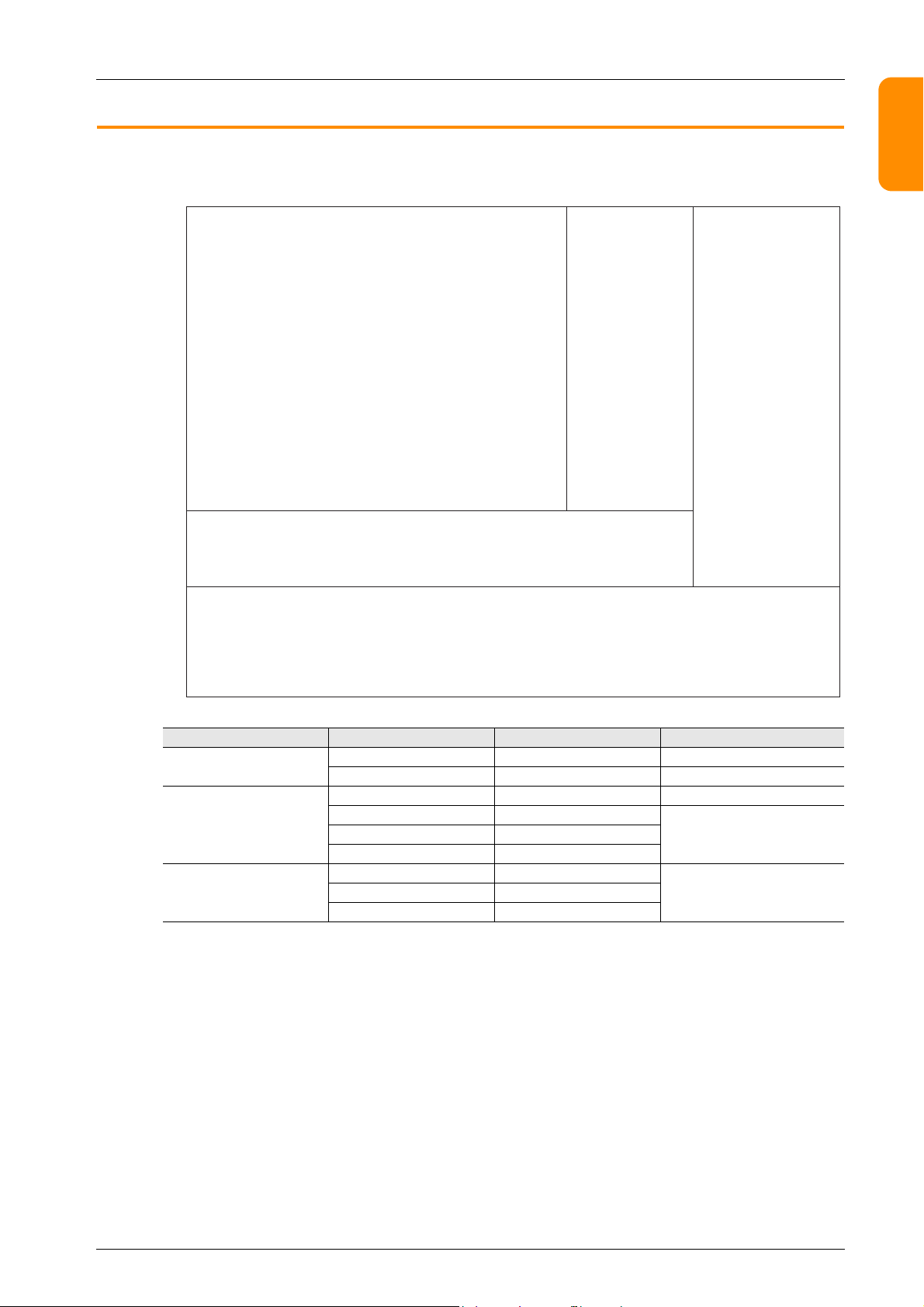
1.1 Edit Model and Resolution
0
639 799
0
479
767
V9100iC / V9080iC / V9060iT
V9120iS / V9100iS / V9080iS
V9150iX
1023
599
V9101iW
V9071iW
X coordinate (dots)
Y coordinate
(dots)
1.1 Edit Model and Resolution
The screen resolution differs between MONITOUCH models.
1
2
3
4
Model Typ e Inches Resolution
V9 Advanced
V9 Standard
V9 Lite
V9101iW 10.1 model 1024 600 (WSVGA)
V9071iW 7.0 model 800 480 (WVGA)
V9150iX 15.0 model 1024 768 (XGA)
V9120iS 12.1 model
V9080iS 8.4 model
V9100iC 10.4 model
V9060iT 5.7 model
800 600 (SVGA)V9100iS 10.4 model
640 480 (VGA)V9080iC 8.4 model
5
6
7
8
9
10
1-1
Page 25
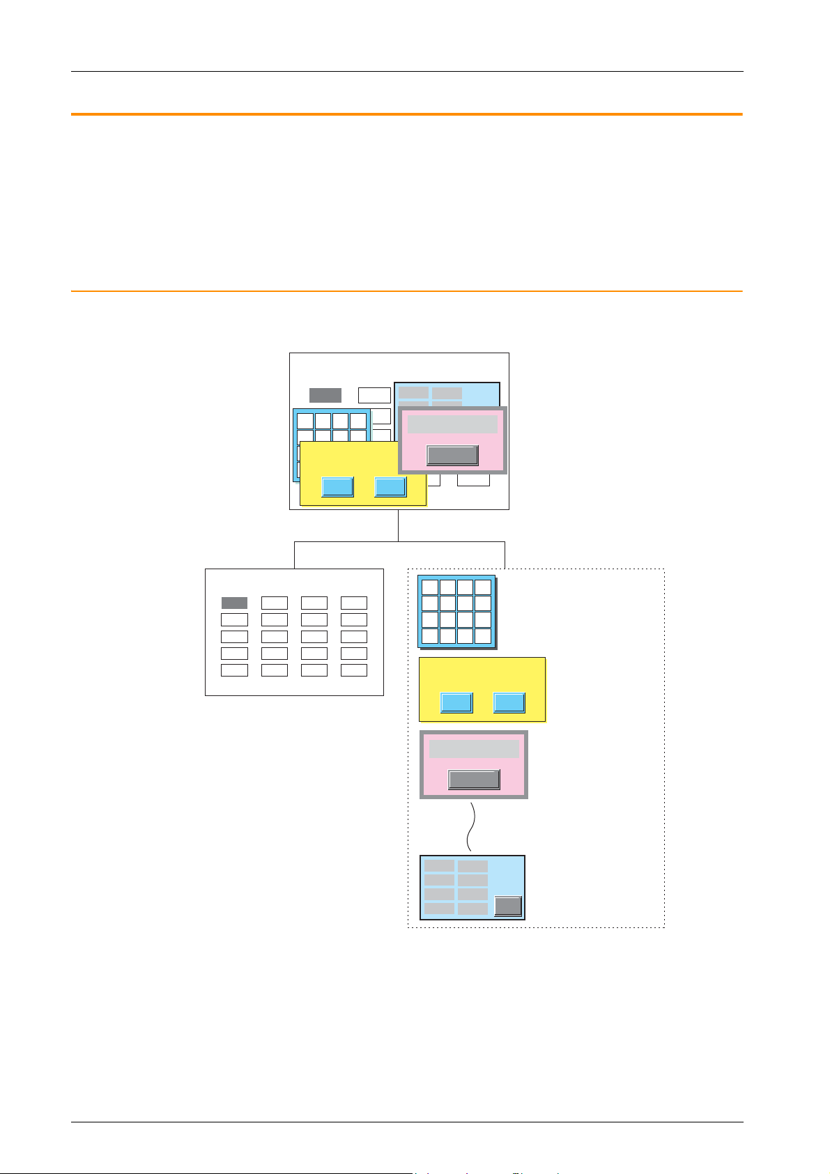
1 Introduction
Line B Monitor
Line-A Error!
Details
Do you want to save
the setting?
YES NO
Line B Monitor
Base screen
Overlaps
Overlap ID 0
Overlap ID 1
Overlap ID 2
Overlap ID 9
Screen
* A maximum of 10 overlaps from overlap ID 0 to ID 9.
Line-A Error!
Details
Do you want to save
the setting?
YES NO
1.2 Screen Program File Structure
The screen program file for MONITOUCH is structured based on an area referred to as a “screen”.
Screens are created by placing various parts and graphic items in the “screen” area.
A single file can store up to 4,000 screens.
Items such as data and graphics which change over time and that cannot be placed directly on screens can be registered to a
separate area and then combined for display on MONITOUCH. (For more information, refer to “6 Registration Items“.)
This section explains the structure of screens.
1.2.1 Screen Structural Components
Each screen is composed of a base screen (mandatory) and overlaps (a maximum of 10 overlaps can be placed).
1135
120
1564
554
1653
10.23
9.89
7.23
11.02
12.03
7 8 9
4 5 6
1 2 3
0 . +/-
1135
120
1564
554
1653
849
988
489
156
484
UP
DW
CL
CR
5548
6615
4485
9981
1165
10.23
9.89
7.23
11.02
12.03
849
988
489
156
484
7 8 9 UP
4 5 6 DW
1 2 3 CL
0 . +/- CR
5548
6615
4485
9981
1165
1-2
Page 26
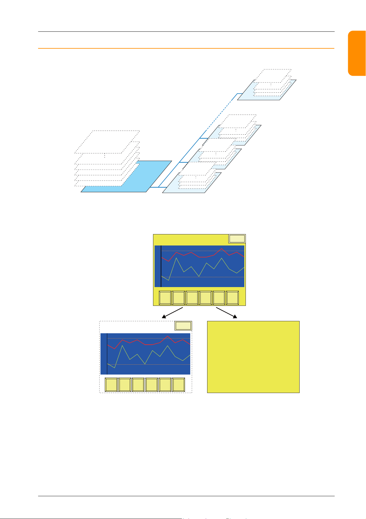
1.2.2 Base Screen/Overlap Display Structure
Base screen
Overlap ID 2
Overlap ID 1
Overlap ID 0
ID 0 to 255
ID 0 to 255
ID 0 to 255
ID 0 to 255
Overlap ID 9
ID 0 to 255
Base screen
ID
Base
Switches, numerical data displays,
display areas, etc.
Graphic parts (texts, boxes, etc.)
Graph
Retur n
Page UpPage
Down
Roll UpRoll
Down
Reset
Trend Sampling
Graph
Retur n
Page UpPage
Down
Roll UpRoll
Down
Reset
Menu
Trend Sampling
Menu
1.2 Screen Program File Structure
Each base screen and overlap contains areas referred to as “IDs.” There are 256 IDs overlaid like invisible sheets.
Parts, such as switches, are placed on sheets from ID 0 to 255 of the base screen and overlaps. These parts are always assigned
numbers identical to their respective sheet numbers (= ID numbers).
Drawing parts, such as text and lines, are placed directly onto the base screen and overlaps. For this reason, these drawing
parts are not assigned ID numbers.
1
2
3
4
400
00
6
5
400
00
7
8
9
10
1-3
Page 27
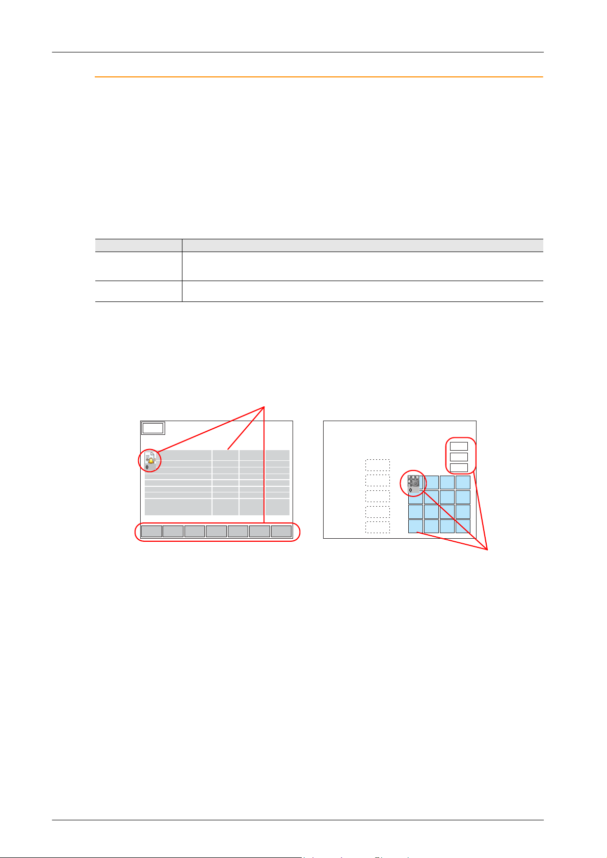
1 Introduction
Error Details
Assign the same ID number to the icon, display area,
and scroll switches.
#2 Roller error
#1 Sensor error
#1 Roller error
#2 Sensor error
#3 Sensor error
#5 Roller error
#4 Sensor error
Alarm History
Assign the same ID.
Entry Screen
Val ue 1
Val ue 2
Val ue 3
Val ue 4
Text 1
Maximum
Minimum
Input
Occurrence
Time
Reset T ime
Acknowledged
Time
What Is an ID?
An “ID” is a number assigned to each invisible sheet.
Each part that comprises a function on the screen is always placed on an invisible sheet. In order to discriminate between
placed sheet numbers, each part is assigned an ID number.
Whether a sheet can contain multiple parts or only one part depends on the types of parts.
The editor automatically performs ID number allocations. Normally, you do not need to worry about the allocation of ID
numbers.
A part that executes its function singly, such as a switch, lamp, numerical data display, or bar graph, has no limit on the
number of parts per ID.
ID numbers do not need to be taken into consideration when placing these types of parts.
Restrictions on identical ID placement
Necessity of ID agreement
Part
Rest ricted
(only one ID per part)
Unrestricted Switches, lamps, data displays (numerical data displays, character displays, message displays), slider switches, bar
Entry mode, trend parts, alarm parts, JPEG display, network camera display, remote desktop display, graphic parts,
message parts, comment parts, animation function, macro mode function, interval timer macro function, sound
function, table data displays, statistic bar graphs, statistic pie graphs, calendar parts, data block areas, and memos
graphs, pie graphs, closed area graphs, panel meters, time displays, and screen libraries
Different parts may be combined to execute a single function, as shown below. Such parts must share the same ID number.
• Error message display (= alarm)
• Numerical data entry on the V9 series unit (= entry mode)
Menu
1234
16:15:43 16:21:12 16:45:20
16:15:51 16:21:54 16:45:20
16:15:52 16:21:55 16:45:20
17:05:02 18:08:01 18:32:15
17:06:31 18:08:01 18:32:15
19:21:30 21:09:44 21:15:00
19:22:45 21:10:22 21:15:00
DWUP
-+
DELRET RESET
1234
1234
12.34
12.34
ABCD
7 8 9
4 5 6
1 2 3
0 . +/-
1234
1234
UP
DW
CL
CR
If the parts are assigned different ID numbers, the function will not work correctly.
Check the ID numbers and assign them correctly.
1-4
Page 28
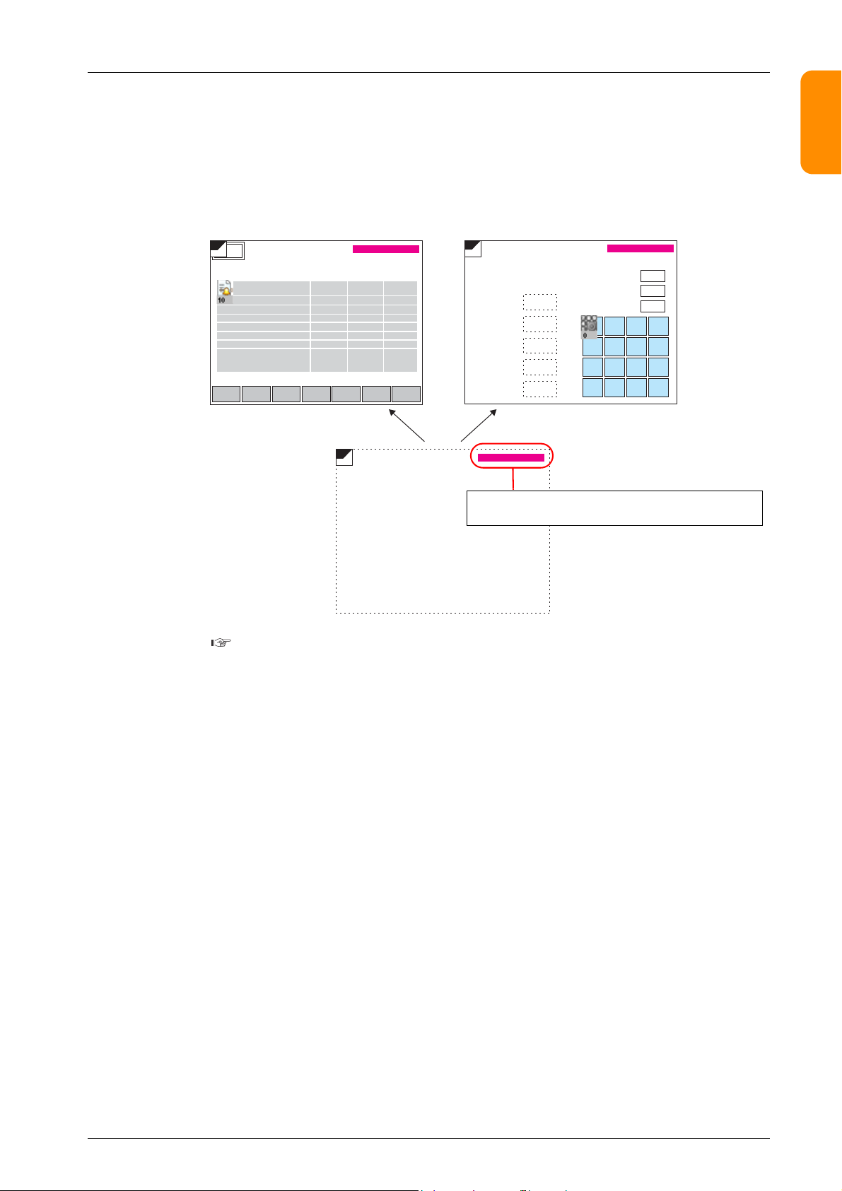
1.2 Screen Program File Structure
E.g. ID number for the alarm part is set to “10”:
#2 Roller error
#1 Sensor error
#1 Roller error
#2 Sensor error
#3 Sensor error
#5 Roller error
#4 Sensor error
Alarm History
ID number for the entry mode part is set to “0”:
Entry Screen
Val ue 1
Val ue 2
Val ue 3
Val ue 4
Text 1
Maximum
Minimum
Input
The ID number of the calendar part on the screen library
must be assigned to a number other than “0” and “10”.
Occurrence
Time
Reset
Time
Acknowledged
Time
Error Details
When using a screen library
With the use of an editing area called “screen library,” a single part can be placed on multiple screens.
Before using this area, check that the ID numbers of parts registered in the screen library are different from the ID numbers of
the parts already placed on screens.
In the case of parts with a placement restriction, using the same ID number will prevent these parts from working correctly.
• Example: When a screen library that contains calendar parts is placed on multiple screens
1
-+
YY/MM/DD hh:mm:ss
DELRET RESET
SLIB
Menu
SLIB
16:15:43 16:21:12 16:45:20
16:15:51 16:21:54 16:45:20
16:15:52 16:21:55 16:45:20
17:05:02 18:08:01 18:32:15
17:06:31 18:08:01 18:32:15
19:21:30 21:09:44 21:15:00
19:22:45 21:10:22 21:15:00
DWUP
For more information on the screen library, refer to “6.5 Screen Library“ page 6-16.
SLIB
YY/MM/DD hh:mm:ss
1234
1234
12.34
12.34
ABCD
YY/MM/DD hh:mm:ss
1234
1234
1234
7 8 9 UP
4 5 6 DW
1 2 3 CL
0 . +/- CR
2
3
4
5
6
7
8
9
10
1-5
Page 29
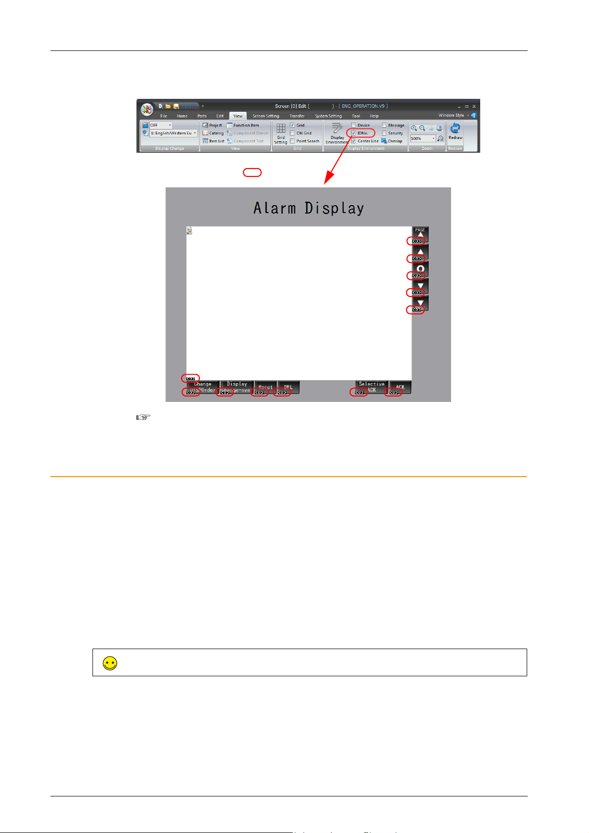
1 Introduction
Sections marked with :
ID number of each part
ID number check
When the [View] [ID No.] checkbox is selected, the ID number of parts placed on the screen can be checked at a glance.
For more information on the [Display Environment] settings, refer to “4.2.4 Display Environment“
page 4-28.
1.2.3 Screen Capacity
• There is no particular limitation on the capacity per screen.
However, there is a limitation on the number of items that can be registered per screen.
For more information, refer to “3.1 Parts Types and Limitations“ page 3-1.
• One file is capable of storing a maximum of 4,000 screens.
• The available capacity per file differs depending on the used font types.
For more information, refer to “Memory Sizes of Fonts“ page 10-4.
• Make sure to check the use environment and perform screen registration such that screens fit into the available capacity
of a single file.
* If a screen program file exceeds the maximum capacity, any attempt to transfer the file will display the alarm
message “The size is too large to communicate” and result in a transfer failure.
The used capacity and remaining capacity for the current screen program can be checked via [Tool] [List of Memory Use].
For more information, refer to “5.3 List of Memory Use“ page 5-3.
1-6
Page 30

2 V-SFT Ver. 6 Configuration
and Screen Editing
Procedures
2.1 Editing Procedure
2.2 Starting and Quitting
2.3 V-SFT Ver. 6 Configuration
2.4 Types of Setting Menus
2.5 Configuring the Editing Environment
2.6 Basic Operations
2.7 Saving Files
2.8 File Comparison
Page 31

2.1 Editing Procedure
Create new screen program
Select a model
Screen editing
Background color settings
Editing environment settings
Parts and item placement
Editing libraries etc.
Saving the screen program file
Transfer to MONITOUCH.
“2.2.1 Starting“ page 2-2
“2.5 Configuring the Editing Environment“ page 2-44
“3 Placing Parts“
“6 Registration Items“
“7 Transfer“
Hardware settings
Model and target port selection
PLC1
Communication settings
Other settings
PLC2 to
Model and target port selection
Communication settings
Other settings
For setting PLC 2 and after:
Control area
“2.5 Configuring the Editing Environment“ page 2-44
“2.2.1 Starting“ page 2-5
“2.2.1 Starting“ page 2-7, V9 Series Connection Manual
“2.7 Saving Files“ page 2-65
2.1 Editing Procedure
Editing Procedure
The following flowchart shows the procedure from creating a new screen program to transferring the created screen program
to the V9 series unit.
1
2
3
4
5
6
7
8
9
10
2-1
Page 32

2 V-SFT Ver. 6 Configuration and Screen Editing Procedures
• Double-click on the desktop shortcut.
Start menu
• Click [V-SFTV6] from the Start menu.
• Double-click “Vsft60.exe” in the installation folder.
E.g.: C:\MONITOUCH\V-SFT V6\VSft60.exe
or
2.2 Starting and Quitting
2.2.1 Starting
Procedure for Creating a New File
1. Start V-SFT version 6 using any of the following methods.
2. The startup menu is displayed.
3. Click [New].
2-2
Page 33

4. The [Edit Model Selection] window is displayed.
Close
Select the MONITOUCH model for which you wish to create a screen program and click [OK].
5. The [PLC1 Connection Device Selection] window is displayed.
Select the PLC model and connection port and click [Finish].
2.2 Starting and Quitting
1
2
3
6. The hardware settings and PLC properties are displayed.
Configure the communication settings in the PLC properties window and then close the PLC properties window.
7. Click [Control Area] and configure the following settings.
[Displaying Screen Device]
[Initial Screen]
4
5
6
7
8
9
10
2-3
Page 34

2 V-SFT Ver. 6 Configuration and Screen Editing Procedures
or
8. Click the [Close] button to close the [Hardware Setting] window.
The [Screen [0] Edit] tab window is displayed.
This completes the settings required to create a new screen program.
Opening an Existing File
1. Start V-SFT version 6.
2. Click [File] [Open].
3. In the [Open] window that appears, select the desired file and click [Open].
2-4
Page 35

4. The file is opened.
2.2 Starting and Quitting
1
2
3
4
V-SFT version 6 can also be started by double-clicking on an existing screen
program file.
Edit Model Selection
Select the MONITOUCH model for which you wish to configure a screen program.
Item Description
Edit Model Select a model.
Installation Select the installation direction of the MONITOUCH.
Size Display resolutions for the selected model are displayed.
Color Select the number of display colors.
5
6
7
8
9
2-5
10
Page 36

2 V-SFT Ver. 6 Configuration and Screen Editing Procedures
The resolution of 640 480 is changed to 800 600
when the MONITOUCH model is changed.
Automatic size adjustment function
When changing the MONITOUCH model of an existing screen program file to another model with a different resolution, the
resolution of the screen program can be adjusted automatically as much as possible at the time of model change.
Procedure for changing the MONITOUCH model
This procedure is explained with an example of changing the model from V9100iC V9100iS.
1. Click [System Setting] [Edit Model Selection].
2. The [Edit Model Selection] window is displayed.
Change [Edit Model] from [V910*iC] (resolution: 640 480) to [V910*iS] (resolution: 800 600) and click [OK].
3. The following confirmation dialog box is displayed.
4. Click [Yes] to execute automatic size adjustment.
Click [No] to only change the MONITOUCH model without adjusting the screen resolution.
• The target areas of the automatic size adjustment function are:
Screens, screen libraries, overlap libraries, graphic libraries, data blocks
• Size adjustment cannot be performed for patterns and animation frames.
• Text is adjusted as much as possible according to the new resolution.
However, note that the size of text in the following functions cannot be adjusted.
Alarm parts, message parts, data display type trend parts
• For video displays, the display size is not changed.
• For features whose size cannot be changed automatically, adjust each of them manually.
2-6
Page 37

Hardware Settings
2.
3.
4.
5.
1.
2.2 Starting and Quitting
Configure the settings of the V9 series unit and the settings of devices that connect to the V9 series unit.
1
2
3
4
5
Item Description
1. Close Close the [Hardware Setting] window.
Set the device (PLC/temperature controller/servo/inverter/barcode reader etc.) for connection
2. PLC Setting/Other Devices
3. Connection diagram
PLC Setting/Other Devices settings
4.
toggle button
5. Unit settings Configure the settings of the V9 series unit.
For details on hardware settings, refer to the V9 Series Connection Manual.
to PLC1 to PLC8.
Click the toggle icon (4) to change the display to [Other Devices].
[Other Devices] is used to configure connection settings for the simulator and any printers.
Displays the devices configured for connection.
Devices and communication settings can be changed.
Switch the display between PLC settings and other settings.
The display changes each time the button is clicked.
6
7
PLC Property Settings
Configure the settings of PLCs connected to the V9 series unit.
Match the communication settings with the settings on the relevant PLC.
8
9
For details on PLC property settings, refer to the V9 Series Connection Manual.
10
2-7
Page 38

2 V-SFT Ver. 6 Configuration and Screen Editing Procedures
Control Area Settings
Specify the device memory to use for switching screens by commands from a connected device.
The initial screen displayed at V9 series unit startup is also set here.
Item Description
This device memory is used for switching the screen via an external command. When a screen
number is specified to this device memory, the screen is displayed.
Specify the screen number to display when power to MONITOUCH is turned on.
If a nonexistent screen number is specified, the lowest screen number in the screen program is
displayed.
Use a screen displaying device
Display the screen of the number stored in the [Displaying Screen Device] memory.
This bit is valid when the built-in clock of the V9 series unit is not used.
This bit should be used differently depending on whether the connected PLC is equipped with a
calendar function.
When connecting to a PLC with a calendar function
When calendar data in the PLC is updated, it can forcibly be read by setting this bit to ON (at
the leading edge of [0 1]).
When connecting to a PLC without a calendar function
Allocate a virtual calendar data area by specifying device memor y for [Calendar Device] and
set the calendar data by setting this bit to ON.
* For more information, refer to the V9 Series Reference Manual 1.
This device memory stores the state of the [Calendar Read Device] memory.
Device] after the screen display operation is complete. In addition to watch dog monitoring,
these device memory addresses can be used for display scanning.
* For more information, refer to the V9 Series Connection Manual.
Screen
Calendar
Setting
Other Settings
Displaying Screen Device
Initial Screen
Control Device For more information, refer to the V9 Series Reference Manual 1.
Info Output Device
PLC Selection Set the reading target of the calendar. PLC1 to 8
Calendar Read Device
Calendar Information
Output Device
Watchdog Device When any data is saved to [Watchdog Device], the same data is also written to [Answer-back
Answer-back Device
Calendar Device For more information, refer to the V9 Series Reference Manual 1.
2-8
Page 39

2.2.2 Quitting
or
2.2 Starting and Quitting
Quit V-SFT version 6 using any of the following methods.
Click the application button [Quit Application],
or click [ ] at the top right of the editor.
1
2
3
4
5
6
7
8
9
10
2-9
Page 40

2 V-SFT Ver. 6 Configuration and Screen Editing Procedures
Quick access toolbar
Ribbon menu
Catalog view window
Project list view window
Function item view windowStatus barItem list view window
Configuration window
Item settings window
Application button
2.3 V-SFT Ver. 6 Configuration
2.3.1 Names of Parts
2-10
Page 41

2.3.2 Application Menu
Application
button
Application menu
This menu is used to set the menu display language of the editor and the font of text registered in item setting windows and
message registration screens.
Item Setting
Language Select the display language to use for menus in the editor.
Text Font Set the font of text registered in item setting windows and message registration screens.
Close Close this menu.
Recent Document Displays up to 10 of the most recently opened screen program files.
Quit Application Quit V-SFT version 6.
2.3 V-SFT Ver. 6 Configuration
1
2
3
4
Language
Select the display language to use for menus in the editor.
The editor must be restarted for any changes to take effect.
Text F ont
Register the font of text set in item setting windows, message registration screens, and comment registration screens for each
language.
When using Windows fonts for items, the font set here is the default font setting.
5
6
7
8
9
10
2-11
Page 42

2 V-SFT Ver. 6 Configuration and Screen Editing Procedures
1. 2. 3. 4. 5. 6.
2.3.3 Quick Access Toolbar
This menu is always displayed. The types of icons that are displayed can be customized.
Item Description
1. New Create a new screen program file.
2. Open Open an existing screen program file.
3. Overwrite Save the screen program.
4. Undo Undo the last operation.
5. Redo Redo the operation that was undone using the [Undo] button.
Customize Quick Access
6.
Toolbar
Customization Procedure
1. Click the mark on the right side of the quick access toolbar to display the customization menu.
Click [More Commands].
Select the menu items to display on the quick access toolbar.
2. The [Customize] window is displayed.
Select the icons to add and click the [Add] button.
2-12
Page 43

3. Check that the icons are added to the right-side window and click [OK].
4. The icons are added to the quick access toolbar.
2.3 V-SFT Ver. 6 Configuration
1
2
3
4
5
6
7
8
2-13
9
10
Page 44

2 V-SFT Ver. 6 Configuration and Screen Editing Procedures
Ribbon menu
2.3.4 Ribbon Menu
Item Description
File
Home Register registration items, switch between the screen for editing, and place primary parts and items.
Parts Place parts and items.
Edit
View
Screen Setting Configure the screen background color and macros, function switches, and function item settings.
Transfer Transfer screen programs and execute the simulation function.
System Setting
Tool Execute helpful functions including error checking, search, and batch device memory change.
Help Refer to manuals and check version information.
Perform operations including new file creation, printing, storage manager startup, file comparison, component
parts editing, and property configuration.
Perform helpful operations during editing including copying, cutting, pasting, grouping, placement, and
arrangement.
Change the state of switches and lamps, switch between multiple languages, show/hide each view window,
configure grid display settings, configure display environment settings, and set the magnification.
Select the model for editing and configure unit settings, communication settings, and function settings common
to all screens.
File
File
Print
Storage
File Management
Component Parts
Other
Item Description
New Create a new screen program file.
Open Open an existing screen program file.
Save Save the file currently being edited (if it is a new file, you must give it a filename.)
Save As Save the file currently being edited to a new file with a different filename.
Print Print out the created screen program file from the printer connected to the computer.
Print Preview Display a preview of printer output. For more information, refer to “9.3 Print Preview“.
Print Current Window Print out the currently open window.
Storage Manager The storage manager is an application that facilitates writing of data used by the V9
Comparing Execute a file comparison. For more information, refer to “2.8 File Comparison“page
New Perform editing of component parts.
Open
Modify
Property Check the information on the current file and configure the editing environment. For
Language Setting Select the display language to use for menus in the editor.
V8 series screen program files can be opened and converted to V9 series screen
program files.
For more information, refer to “9.2 Printing“.
series unit to a storage device, such as an SD card or USB flash drive, and importing
of data from a storage device for conversion into other file formats. For more
information, refer to “8 Storage Device” in the V9 Series Reference Manual 2.
2-66.
For more information, refer to “11.4 Component Parts“.
more information, refer to page 2-15.
2-14
Page 45

2.3 V-SFT Ver. 6 Configuration
[Property] window
Item Description Refer to
File Information Set a file comment and change the password. page 2-15
PLC Information Displays the set PLC information. page 2-16
General Configure environment settings, such as title displays and automatic
Edit Configure editing environment settings. page 2-17
Transfer Configure message transfer settings for selective transfers and text. page 7-39, page 7-45
Splash Screen Configure these settings when displaying a splash screen. V9 Series Reference Manual 2
saving.
page 2-16
1
2
3
4
[File Information]
Item Description
File Name Displays the name of the screen program file and the path of the storage target folder.
File Comment
(16 one-byte
characters/8 two-byte
characters max.)
Change Password
(6 one-byte
alphanumeric characters
max.)
A comment for the current screen program file can be entered.
The entered comment is transferred together with the screen program f ile to MONITOUCH and can be checked
in Local mode.
It is possible to prohibit screen program files from being opened in the editor. Once a password is set here, the
password must be subsequently entered each time the file is opened or when displaying data loaded from
MONITOUCH. A password ensures security against unauthorized access.
5
6
7
8
9
Manage the password on your own. Note that Hakko Electronics is not liable for any damages resulting from unknown or
forgotten passwords.
10
2-15
Page 46

2 V-SFT Ver. 6 Configuration and Screen Editing Procedures
[PLC Information]
This tab shows the device names designated as PLC 1 to PLC 8 in the [Hardware Setting] window.
[General]
Configure environment settings, such as title displays and automatic saving.
2-16
Item Description
Contracted Display * Shorten the product name displayed in the window title at the top of the editor.
Display File Path *
Backup File Creation
Auto Save
Limit the number of open screens
Display Item in Movement
Prohibit Item View Display by Single Click Double-click to display the item view window, such as for drawing parts.
No Docking Select this checkbox to prevent item view windows from being inset into the editing screen.
Display the path of the screen program file in the window title at the top of the editor.
When this checkbox is unselected, the path is not displayed.
Always create a backup file (with extension “*.bak”) when saving a screen program file. (Data
previously saved is saved as a backup file, which is different from the saved data.) If
unnecessary, deselect the checkbox.
Automatically save the screen program file at regular intervals (setting range: 10 to
60 minutes).
When auto-saving a newly created screen program for the first time, you will be prompted to
name the file.
The auto-save function does not work when the macro editing window or the message
window is open.
Set the maximum number of windows that can be open when the editor is running.
When this checkbox is unselected, you can open as many windows as possible.
Display parts graphically on the editor while moving them.
When this checkbox is unselected, a dotted box showing the part size is displayed instead.
Page 47

* Title display examples
[Contracted Display] target
[Contracted Display] selected/[Display File Path] selected
[Contracted Display] selected/[Display File Path] unselected
[Contracted Display] targetFile path
[Edit]
Configure editing environment settings.
2.3 V-SFT Ver. 6 Configuration
1
2
3
4
Item Description
Remap Menu Switches (Screen/Screen
Library/Overlap)
Use a different attribute to each line in a switch/lamp When registering text for switches and lamps, allow different text properties on each
Use 2D parts as default Place 2D parts as the default parts when placing parts from the menu.
[Transfer]
For more information, refer to “7.7 Selective Transfer“ page 7-39 and “7.8 Message/Comment Transfer“ page 7-45.
When moving screens or overlaps, on the [Screen List] tab window for example,
automatically remap values such as switch target numbers as well as associated
functions.
For more information, refer to page 2-58.
line.
5
6
7
8
9
10
2-17
Page 48

2 V-SFT Ver. 6 Configuration and Screen Editing Procedures
[Splash Screen]
Set the screen that is displayed when the V9 series unit starts up. For more information, refer to the V9 Series Reference
Manual 2.
Home
Screen
Parts
Graphic
Item Description Refer to
Regis tration
Item
Previous Screen Displays the previous screen. “2.6 Basic Operations“
Next Screen Displays the next screen.
Skip Select this checkbox to skip unregistered screens when changing between
Screen List Displays a list of screens being edited or overlap libraries.
Overlap Place an overlap. “3.4 Placing and
Switch Place a switch.
Lamp Place a lamp.
Data Display Place a data display (numerical data display, character display, message display,
Entry Place a keypad for entry and entry mode icon.
Trend Place trend parts.
Alarm Place alarm parts.
Time Display Place a time display part and calendar part.
Shape Place parts including line, rectangle, circle, paint, dot, and pattern. “3.6 Shape and Text
Text Place text and multi-text.
Pattern Place an image file pasted as a picture part, pattern, or other part.
Configure registration items, such as overlap libraries and messages. “6 Registration Items“
screens.
Setting Parts“
table data display).
Graphics“
2-18
Page 49

Parts
2.3 V-SFT Ver. 6 Configuration
1
Item Description Refer to
Catalog
Overlap Place an overlap. “3.4 Placing and
Switch Place a switch.
Lamp Place a lamp.
Data Display Place a data display (numerical data display, character display, message display,
Entry Place a keypad for entry and entry mode icon.
Trend Place trend parts.
Parts
Graphic
Component Parts Place a component part. “3.7 Component Parts“
Alarm Place alarm parts.
Graph Place a bar graph, pie graph, closed area graph, panel meter, statistic bar graph,
Time Display Place a time display part and calendar part.
Image Display Place a video/RGB display, JPEG display, network camera display, and remote
Graphic Place a graphic part.
Message Place message parts and a comment part.
Others Place recipe parts, slider switch, data block area, and memo pad parts.
Shape Place parts including line, rectangle, circle, paint, dot, and pattern. “3.6 Shape and Text
Text Place text and multi-text.
Pattern Place an image file pasted as a picture part, pattern, or other part.
Display the parts catalog. “3.2.2 Placement from
table data display).
and statistic pie graph.
desktop display.
the [Catalog] View
Window“
Setting Parts“
Graphics“
2
3
4
5
6
7
8
9
2-19
10
Page 50

2 V-SFT Ver. 6 Configuration and Screen Editing Procedures
Edit
Item Description Refer to
Paste Paste the item on the clipboard onto the screen. “4.1.1 Edit“
Copy Copy the selected item to the clipboard.
Multi-copy Copy the selected item and paste multiple instances of the item.
Cut Cut the selected item and move it to the clipboard.
Edit
Place
Put All in Same Size Change the size of multiple selected items to that of a reference part. “4.1.3 Size“
Style Change the color, style, and text font of graphic parts. “4.1.4 Style“
Modify
Parts
Setting Selection
Select/
Delete
Delete Delete the selected item.
Undo Restore the screen to the state before the last action was performed.
Redo This command becomes active when [Undo] is performed. Click this button to
Selection Pasting Copy the selected item and paste it onto the specified screen.
Bring to Front Move the selected item into the foreground. “4.1.2 Place“
Send to Back Move the selected item into the background.
Place Align the placement position of multiple selected items.
Arrangement Arrange multiple selected items vertically or horizontally at regular intervals.
Rotate Rotate the selected item.
Group Group or ungroup multiple selected items.
Link Set the ID of multiple selected items to the same ID. “3.3 Changing a Part
Change Part Edit the selected item. “11 Parts Editing“
Vertex Edit Use this command to change the angular position or radius of polygons.
Drawing Method Change the drawing method used for polygons and round parts.
Environment
Setting
Select All Select all items on the screen. “4.1.7 Select/Delete“
Delete All Delete all items on the screen.
restore the screen to the state before [Undo] was executed.
Or undo selection pasting.
Change the types of parts that can be selected using the mouse. “4.1.6 Selection
After Placement“
Environment Setting“
2-20
Page 51

View
2.3 V-SFT Ver. 6 Configuration
1
Item Description Refer to
Display
Change
View
Grid
Display
Environment
Zoom Zoom In Increase the display magnification of the screen. “4.2.5 Zoom“
Redraw Redraw the screen. “4.2.6 Redraw“
State Change Change the display state of switches and lamps. “4.2.1 Display Change“
Language
Display
Project Display the project list view window. “4.2.2 View“
Catalog Display the catalog view window.
Item List Display the item list view window.
Function Item Display the function item view window.
Component
Device
Component Text Display the component text view window.
Grid Setting Display the [Grid Setting] window. “4.2.3 Grid“
Grid Display a grid in the editing area.
ON Grid Snap items to the grid.
Point Search Place the selected item on the vertex of another item.
Display
Environment
Device Display the device memory set for parts.
IDNo. Display the ID number of parts.
Center Line Display center lines in the editing area.
Message Display the messages set for items such as alarm parts.
Security Display the set security level.
Overlap Show or hide placed overlaps.
Zoom Out Reduce the display magnification of the screen.
100% Display the screen at 100% magnification.
Fit in Display
Area
Scaling Display Display the screen at the specified magnif ication.
Change the display language number when using multi-language screens.
Display the component device view window.
Configure detailed display environment settings. “4.2.4 Display
Display the screen at a magnification that matches the display range of the
editor.
Environment“
2
3
4
5
6
Screen Setting
Item Description Refer to
Screen Setting Set items unique to the current screen, such as screen background and
Screen Setting
Function
Switch
Function
Open Macro Register an open macro. V9 Series
Close Macro Register a close macro.
Cycle Macro Register a cycle macro.
Local Function
Switch Setting
Sound Register a sound function. V9 Series
Animation Register an animation.
Macro Register a macro mode. V9 Series
Interval Timer Register an interval timer macro.
comments.
Configure local function switch settings. V9 Series
“4.3.1 [Screen
Setting] Window“
Macro Reference
Reference Manual 1
Reference Manual 2
Macro Reference
7
8
9
10
2-21
Page 52

2 V-SFT Ver. 6 Configuration and Screen Editing Procedures
Transfer
Item Description Refer to
Download Write the screen program to the V9 series unit. “7 Transfer“
Upload Read the screen program from the V9 series unit.
Tr an sf er
Simulation
File Comparing Compare the program in the editor with the program on the V9 series unit.
Communication
Setting
Simulator Start the simulator. “8 Simulation“
Emulator Start the emulator.
Configure the settings for communication between the PC and V9 series
unit.
System Setting
Unit Setting
Communication
Setting
Common
Setting
Setting
Item Description Refer to
Edit Model Selection Select the V9 series model for which to configure a screen program. V9 Series
Multi-language
Setting
Unit Setting Configure settings for the V9 series unit, such as the backlight and
Hardware Setting Select the types of controller models connected to the V9 series unit. V9 Series
Device Memory Map Configure the settings to use when performing batch data transfer or
Ethernet
Communication
Global Setting Configure global function switch settings and global overlap settings. V9 Series
Alarm Server Configure alarm server settings.
Logging Server Configure logging server settings.
Recipe Configure recipe settings.
Scheduler Configure scheduler settings. V9 Series
Other Configure storage settings, memory card settings, MES settings,
Macro Setting Set the initial macro, global macro, and event timer macros. V9 Series
Date and Time
Display Setting
Japanese Conversion
Function Setting
Set the languages displayed on the V9 series unit.
buzzer.
sampling between controllers.
Configure the local port (V9 series) IP address, network table, email, and
FTP server settings.
operation log settings, security settings, remote desktop table settings,
network camera table settings, time display format settings, and scrolling
message settings.
Set the date and time format to display for items such as alarm parts. V9 Series
Select this checkbox to use the Japanese conversion function.
Reference Manual 1
Reference Manual 1
V9 Series
Reference Manual 2
Reference Manual 1
Reference Manual 2
Macro Reference
Reference Manual 1
2-22
Page 53

Tool
2.3 V-SFT Ver. 6 Configuration
1
Item Description Refer to
Error Error Check Perform an error check on the screen program currently being configured. “5.2 Error Check“
Search
Batch Change
Others
List of Memory Use Display the available capacity of the screen program currently being
Search Search device memory addresses, tag usage, text, Windows fonts, and
Device Perform a batch change of device memory addresses. “5.5 Batch Change“
Windows Font Perform a batch change of W indows fonts.
Multi Language Perform a batch change of properties such as language switching and text
Cursor Order INC Perform a batch change of cursor movement order numbers.
Screen Library Perform a batch change of specified numbers of screen libraries placed on
Fix 3D parts frame Perform a batch change of the frame size of real type and 3D square type
Other Perform a batch change of overlap transparency settings. -
Screen Image Capture an image of the displayed screen.
Convert to Rich Text
Format
DXF File Convert Import a DXF file into the screen program currently being configured.
configured.
macro commands.
color.
the screen.
parts.
Select from the three commands of saving as a pattern image, copying to
the clipboard, and saving to an image file.
Save an image of the screen program currently being configured to a rich
text format file.
(extension: *.RTF)
“5.3 List of Memory
Use“
“5.4 Search“
“5.6 Others“
Help
2
3
4
5
Item Description
Manual Refer to manuals in PDF format.
Manual
Download Display the website for downloading manuals.
V-UG Type List Reference the V series/UG series type comparative table.
Version Information Check detailed version information for V-SFT version 6.
• V9 Series Hardware Specifications
• V9 Series Connection Manual 1/2/3
• V9 Series Reference Manual 1/2
• V9 Series Operation Manual (this manual)
•V9 Series Macro Reference
• V9 Series Troubleshooting and Maintenance Manual
• V9 Series Training Manual Beginner’s Guide/Practical Guide
• V9 Series Setup Manual
6
7
8
9
2-23
10
Page 54

2 V-SFT Ver. 6 Configuration and Screen Editing Procedures
1.
2.
3.
4.
6. 7.
5.
2.3.5 Item Settings Window
This window is displayed by double-clicking on a placed item. The settings of parts can be checked and changed.
The categories of settings are displayed on the left side of the window. Select a category for conf iguration.
Item Description
1 Setting categories Displays the setting categories available for the part.
2 Other Settings Add categories that are not displayed to the setting categories.
3 Preview Display Temporarily hide the item settings window and display the preview window.
4 Detailed settings Configure the settings of the selected setting category.
5 Comment Register a comment for the part. This is used in the operation log function.
* For details on operation logs, refer to the V9 Series Reference Manual 2.
6 Finish Accept any part settings made and close the item settings window.
7 Cancel Cancel any part settings made and close the item settings window.
Other Settings
Add category menus that are not displayed to the setting category display area on the left side of the window.
Click the [Other Settings] button and select the category to add to the setting category display area.
2-24
Page 55

Preview Display
Double-click
Click
2.3 V-SFT Ver. 6 Configuration
Temporarily hide the item settings window and display a preview of the screen for checking purposes.
Double-click the preview screen to return to the item settings window.
1
2
3
4
5
6
7
8
2-25
9
10
Page 56

2 V-SFT Ver. 6 Configuration and Screen Editing Procedures
4
1
2
3
5
6
7
Style Settings of Linked Parts
The [Style] category is used to configure the settings of linked parts, such as adding or deleting associated switches and
numerical data displays and changing the style and placement position of parts.
Item Description
1 Preview pane Displays a preview of the part.
2 Adjust Position Display the position adjustment window. After changing the position of parts, double-click the linked parts to
3Select from
catalogs
4 Additional Parts
List
5 Add Parts Use this button to add associated parts that are not displayed under [Additional Parts List].
6 Parts Design This is displayed when a part in the preview pane is selected.
7 Edit Selected Parts This is displayed when a part in the preview pane is selected.
return to the item settings window.
Select the design of linked parts from the catalog.
Select the checkboxes of the associated function parts to use, such as switches and numerical data displays.
Set the type and color of the selected part.
Set the displayed text and text properties for the part.
Click [Others] to display the item settings window for the part selected in the preview pane and change the
part’s settings.
For more information of the setting items for each part, refer to the V9 Series Reference Manual 1 and 2.
2-26
Page 57

Position adjustment procedure
2.3 V-SFT Ver. 6 Configuration
1. Click the [Adjust Position] button to display the position adjustment window.
1
2
3
4
2. First, click on an empty area of the screen so that nothing is selected.
5
6
7
8
2-27
9
10
Page 58

2 V-SFT Ver. 6 Configuration and Screen Editing Procedures
3. Next, select the parts to move and drag the parts to change their position.
2-28
4. After changing the position of the parts, double-click the screen to return to the item settings window.
Page 59

2.3 V-SFT Ver. 6 Configuration
[Select from catalogs]
Click this button to display the [Part Type Select] window.
Specify settings for [Shape] and [Group] and select the desired parts.
[Additional Parts List]
Select the checkboxes of the associated function parts to use, such as switches and numerical data displays. Deselect the
checkboxes of any unnecessary parts to delete them.
• E.g.: Deleting the [Reset] switch
1
2
3
4
5
6
7
8
2-29
9
10
Page 60

2 V-SFT Ver. 6 Configuration and Screen Editing Procedures
[Add Parts]
Click the [Add Parts] button to select additional parts. Selecting a part will display the item settings window for the part.
Select any functions and required items and click [Finish] to add parts to the linked parts.
• E.g.: Adding [Currently Selected Value Display] for a numerical data display
2-30
Page 61

2.3.6 View Windows
Drag and drop
2.3 V-SFT Ver. 6 Configuration
Display Method
Use [View] on the ribbon menu to select and display the respective view window.
Types of View Windows
Project list view window
Use this view window to check and change system settings and settings of registered items.
1
2
3
4
For more information, refer to “4.2.2 View“.
Catalog view window
Use this view window when placing parts. Select parts and place them on the screen.
5
6
7
8
For more information, refer to “3.2.2 Placement from the [Catalog] View Window“.
9
10
2-31
Page 62

2 V-SFT Ver. 6 Configuration and Screen Editing Procedures
Audio output is set.
Item list view window
This view window displays a list of items placed on the screen.
To change the settings of items that are diff icult to locate or select, use this window to easily select the item for changing.
For more information, refer to “4.2.2 View“.
Function item view window
Configure and check items that do not have an area on the screen (such as audio, animations, macro modes, and interval
timer macros).
For more information, refer to “4.2.2 View“.
2-32
Page 63

Movement Method
Drag
Drag
2.3 V-SFT Ver. 6 Configuration
Displayed view windows can be moved in the editor.
Double-click on the title bar of a view window or drag the title bar and move it to another position to change the window to
the floating state.
1
2
3
4
Docking
Double-click on the title bar of a view window or drag the title bar and move it to dock the window in the editor.
5
6
7
8
9
10
2-33
Page 64

2 V-SFT Ver. 6 Configuration and Screen Editing Procedures
Enter the desired value
directly.
2.4 Types of Setting Menus
2.4.1 Menu Types
Pull-down Type
• Click the arrow button or item itself to bring up the pull-down menu.
• Click the desired item and then click [OK].
Option Button
• This button is used when there are two to four choices.
Numerical Data Entry: Box Type
• Change the value using the up/down arrow buttons.
• A value can also be entered directly.
2-34
Page 65

Numerical Data Entry: Underlined Type
Click
• Clicking the underlined data brings up the data entry menu.
Enter the desired value in the data entry menu.
2.4 Types of Setting Menus
1
2
3
4
Checkbox
• Clicking the checkbox displays a check mark and enables the setting.
5
6
7
8
9
10
2-35
Page 66

2 V-SFT Ver. 6 Configuration and Screen Editing Procedures
Scroll bar
List Type
• Clicking an item displayed in the list highlights it.
This indicates that the item is selected.
• If some options are hidden, they can be displayed using the scroll bar.
Command Buttons
• Clicking a command button moves to the next editing window or finishes the current editing task.
Detailed Settings>>
• Clicking this text displays additional settings.
2-36
Page 67

2.4.2 Device Memory Settings
Right-click
Click
2.4 Types of Setting Menus
There are three methods for specifying device memory such as PLC device memory and internal device memory.
Select a method that facilitates configuration.
Changing the Specification Method
Right-click at the following location on a device memory setting to show the display selection menu for device memory.
The specification method can be changed by selecting the desired display type.
Device Memory Display Types and Specification Methods
Normal display
Clicking on a device memory setting item displays the [Device Input] window.
Specify the device memory in this window.
1
2
3
4
Normal display (no input window)
Directly specify the device memory using the device memory settings item. The [Device Input] window is not displayed.
• Selection method
1) Select the device memory type and address type from the pull-down menu.
5
6
7
8
9
10
2-37
Page 68

2 V-SFT Ver. 6 Configuration and Screen Editing Procedures
Enter the value directly.
Change using the up/down arrow button.
or
Click
* Values cannot be directly entered into the
numerical data field.
However, when the up/down arrow button is
shown, the value can be selected using the
arrow button.
E.g.: Mitsubishi [A Series Link] (1:1)
E.g.: Yokogawa [FA-M3] (1:1)
E.g.: Mitsubishi [A Series Link] (1:n)
(Slot number to be set for SW and SL)
2. Port number (Unit number to be set for SPU)
(Unit number to be set for SPU)
1. CPU number
(Unit number to be
set for SW and SL)
2) Change the value using the up/down arrow button next to the input field or directly enter the desired value into the
field.
Simple display
A red keypad icon is displayed next to the device memory settings item.
Clicking on the keypad icon displays the [Device Input] window.
Specify the device memory in this window.
Types of Device Memory
PLC device memory
Set the device memory of connected PLCs.
Item Description
1. CPU number This is displayed when Yokogawa [FA-M3] etc. is selected.
2. Port number This is displayed when the connection mode is set to [1:n].
2-38
Page 69

2.4 Types of Setting Menus
Internal device memory
Set the device memory area allocated on the V9 series unit.
Item Description
$u User device memory
$L/$LD User device memory (non-volatile device memory)
$T User device memory (screen-specific device memory)
$M User device memory (macro device memory)
$MC User device memory (macro device memory in bytes)
$C User device memory (for component parts)
$s System device memor y
$P System device memory (for 8-way communication)
For more information on the definition and range of internal device memory, refer to the V9 Series
Reference Manual 1.
Address list
The address list becomes available when devices such as a temperature controller or inverter is used.
Click the calculator icon to display the [Device Input] window.
1
2
3
4
Clicking the [Open] button displays the address list of the selected temperature controller.
5
6
7
8
2-39
9
10
Page 70

2 V-SFT Ver. 6 Configuration and Screen Editing Procedures
The selected address is displayed.
Click
Select the desired address and click the [Select] button to select the memory address and return to the [Device Input] window.
I/O device memory
This device memory is available when using communications that supports T-LINK I/O communications.
2-40
Page 71

2.4.3 Color Settings
Yellow is selected as
the foreground color.
2.4 Types of Setting Menus
Color Type Setting
Select the color type by clicking [System Setting] [Edit Model Selection] [Color].
Color Type Description
64K-Color w/o blinking Setting of 65,536 colors is possible. Blinking cannot be specified.
32K-Color w/ blinking Setting of 32,768 colors is possible. Blinking can be additionally specified.
Color Selection Procedure
1. Click the “ ” button on the right of the color change icon or the color change button.
A drop-down list for color selection is displayed.
1
2
3
4
2. Click the desired color in the pull-down menu.
The clicked color is applied as the color of the specified item(s) and/or the color change icon.
If the desired color is not displayed in the pull-down menu, click [Custom Color].
The [Custom Color] window is displayed.
5
6
7
8
9
10
2-41
Page 72

2 V-SFT Ver. 6 Configuration and Screen Editing Procedures
•Pallet 1
•Pallet 2
•Pallet 3
[Custom Color] Window
Select any color from a palette of 64k or 32k colors.
Clicking [Palette 1], [Palette 2], or [Palette 3] displays the corresponding color palette. Click the desired color and then click
[OK] to display the graphic item in the selected color.
If none of these pallets include the desired color, click the [Select Color] button to enlarge the [Custom Color] window with a
section of more detailed color settings.
Click anywhere on the circle to display the color at the clicked point next to [New].
For further color adjustments, use the bar slider or change the values of each individual color component.
When the desired color has been created, click the [Add Color] button to register the new color and display it in the bottom
two rows of the color palette, from the top left box in order.
2-42
Page 73

Blinking Setting
2.4 Types of Setting Menus
• Blinking is displayed using the screen’s background color ([Screen Setting] [Screen Setting]) and a specified color.
• Blinking can only be specif ied when [32K-Color w/ blinking] is selected for [Color] in the [Edit Model Selection] window.
Blinking setting procedure
1. Click the [ ] button on the right of the color change icon or the color change button.
2. Select [Blink] in the displayed color selection pull-down menu.
A check mark appears next to [Blink].
3. Click a color as desired.
The clicked color is applied as the color of the specified item(s) and/or the color change icon.
Also, “B” is displayed on the icon, indicating that the blinking setting has been made.
1
2
3
4
Blinking time setting
It is possible to change the blinking interval. Set as described below.
1. Select [System Setting] [Unit Setting] [Blink/Flash].
The [Unit Setting] window is displayed.
2. Set [OFF T ime] and [ON Time] on the [Blink/Flash] tab.
5
6
7
8
The specified blinking time is applied to the entire screen program file. The blinking time cannot be changed for individual
items.
9
10
2-43
Page 74

2 V-SFT Ver. 6 Configuration and Screen Editing Procedures
2.5 Configuring the Editing Environment
2.5.1 Changing the Background Color
1. Set the background color on the [Main] tab accessed by clicking [Screen Setting] [Screen Setting].
2. Click the [Back Color] button. Select the desired color in the displayed color selection pull-down menu.
2-44
Page 75

2.5 Configuring the Editing Environment
3. The selected color is displayed on the [Back Color] button icon. Clicking [OK] changes the background color.
Click [Custom Color] to select a color that is not shown in the drop-down list.
Other colors can be selected in the [Custom Color] window.
1
2
3
4
5
6
7
8
2-45
9
10
Page 76

2 V-SFT Ver. 6 Configuration and Screen Editing Procedures
Center line
Grid
or
Right-click
2.5.2 Grid Display
What Is the “Grid”?
The grid is used as a guide for placing graphics and parts. This is only displayed in the editor and not on the V9 series unit.
The grid can be displayed by selecting the [View] [Grid] checkbox.
In addition to the grid, center lines can also be shown or hidden.
Select the [View] [Center Line] checkbox to show the center lines and deselect the checkbox to hide the center lines.
Detailed Grid Settings
Grid settings can be set by clicking [View] [Grid Setting] or by right-clicking on the screen [Grid] [Grid Setting].
For more information on the setting items, refer to “4.2.3 Grid“.
2-46
Page 77

2.5.3 Changing the Handle Color
Handles
2.5 Configuring the Editing Environment
The color of handles displayed when parts are selected can be changed.
1. Click [View ] [Display Environment]. The [Display Environment] window is displayed.
1
2
3
4
2. Change [Handle Color] on the [Others] tab and click [OK].
5
6
7
8
9
10
2-47
Page 78

2 V-SFT Ver. 6 Configuration and Screen Editing Procedures
Margin color
2.5.4 Changing the Margin Color
The color of the editing area periphery in the editor can be changed.
1. Click [View ] [Display Environment]. The [Display Environment] window is displayed.
2. Change [Margin Color] on the [Others] tab and click [OK].
2-48
Page 79

2.6 Basic Operations
Next screenPrevious screen
2.6 Basic Operations
2.6.1 Screen Switching Procedure
Switching Screens on the [Home] Menu
Previous screen/Next screen icons
Click on the [Previous Screen] and [Next Screen] icons to switch between displayed screens.
If the [Skip] checkbox is selected, unregistered screens are not displayed.
Jump
1. Click [Home] [Jump].
A window for specifying a number is displayed.
1
2
3
4
2. Specify the desired number and click [OK].
The corresponding screen appears.
5
6
7
8
9
2-49
10
Page 80

2 V-SFT Ver. 6 Configuration and Screen Editing Procedures
Display screen by
double-clicking.
Selecting from the Screen List
1. Click [Home] [Screen List].
2. The [Screen List] tab window is displayed.
3. Double-click the number of the desired screen. The corresponding screen appears.
* The screen called by double-clicking is displayed in addition to the [Screen List] window and any screens which
are already displayed.
2-50
Page 81

Selecting from the Project List View Window
Project list view window
2.6 Basic Operations
1. Click [View] [Project].
2. The project list view window is displayed.
1
2
3
4
3. Double-click [Screen] under [Registration Item] to display the registered screens in the project list view window.
5
6
7
8
9
10
2-51
Page 82

2 V-SFT Ver. 6 Configuration and Screen Editing Procedures
Double-click the number.
The corresponding screen (e.g. screen No. 4) is displayed.
* The called screen is displayed in addition to any already
displayed screens.
Drag
4. Double-click on the screen or select the screen and click [Edit] to display the corresponding screen.
The display of multiple screens can be tiled by dragging the tab title as shown below.
2-52
Page 83

2.6.2 Copying Screens
Drag
2.6 Basic Operations
Copy Using the Screen List
1. Click [Home] [Screen List] to display the [Screen List] window.
2. Click to select the copy source screen. (The number is highlighted in red.)
1
2
3
4
3. Drag the copy source screen to the copy destination number.
The copied screen is pasted to the copy destination.
5
6
7
8
9
10
2-53
Page 84

2 V-SFT Ver. 6 Configuration and Screen Editing Procedures
Right-click
Right-click
• In addition to dragging, screens can also be copied by right-clicking on a screen, selecting [Copy] with the copy source
selected, clicking the copy destination, and then selecting [Paste] from the right-click menu.
• When a screen already exists at the copy destination, an overwrite confirmation message appears.
Click [OK] to overwrite the existing screen.
2-54
Page 85

Copy Using the Project List View Window
Project list view window
2.6 Basic Operations
1. Click [View] [Project] to display the [Project View] window.
1
2
3
4
2. Double-click [Screen] under [Registration Item] to display the registered screens in the project list view window.
5
6
7
8
9
10
2-55
Page 86

2 V-SFT Ver. 6 Configuration and Screen Editing Procedures
3. Select the screen to copy and click [Copy] to display the window for specifying the copy destination number.
4. Specify the copy destination and click [OK] to paste the screen.
2-56
Page 87

2.6.3 Moving Screens
1234
1234
1234
1234
12.34
12.34
ABCD
0 . +/- CR
1 2 3 CL
4 5 6 DW
7 8 9 UP
1234
XXXXX
XXXXX
XXXXX
XXXXX
XXXXX
RUN
STOP
RUN
STOP
RUN
STOP
RUN
STOP
XXXXXXX XXXXXXX
XXXXXXX XXXXXXX
XXXXXXX XXXXXXX
XXXXXXX XXXXXXX
1234
1234
1234
1234
12.34
12.34
ABCD
0 . +/- CR
1 2 3 CL
4 5 6 DW
7 8 9 UP
1234
XXXXX
XXXXX
XXXXX
XXXXX
XXXXX
RUN
STOP
RUN
STOP
RUN
STOP
RUN
STOP
XXXXXXX XXXXXXX
XXXXXXX XXXXXXX
XXXXXXX XXXXXXX
XXXXXXX XXXXXXX
Menu Monitor Display Entry Screen
Menu Monitor DisplayEntry Screen
Screen No. 0 Screen No. 1 Screen No. 10
Screen No. 0 Screen No. 1 Screen No. 2
2.6 Basic Operations
There may be cases where you need to exchange or change the screen numbers of registered screens.
Screen numbers can be easily changed by using unregistered screen numbers.
Move Using the Screen List
1
2
3
4
This section explains the procedure for moving screen number 2 to screen number 3.
1. Click [Home] [Screen List] to display the [Screen List] window.
5
6
7
8
9
10
2-57
Page 88

2 V-SFT Ver. 6 Configuration and Screen Editing Procedures
Right-click
[Screen Change-over]
switch
• Before move
•After move
2. Click screen number 2. (The number is highlighted in red.)
Right-click on the screen and select [Move].
3. A window for specifying the destination screen number for the selected screen is displayed. Enter the destination screen
number and click [OK].
4. Screen number 2 is moved to screen number 3.
• Automatic Conversion of Functions
By using the following setting, switches for which [Function] is set to [Screen Change-over] in the screen program and
[Switch to] is set to screen number 2 are all automatically changed to screen number 3.
Location of setting:
Select the [Remap Menu Switches (Screen/Screen Library/Overlap)] checkbox at [File] [Property] [Edit].
Details of change:
2-58
Page 89

Move Using Screen Settings
E.g.: Specifying screen number 1 when
screen number 1 already exists
2.6 Basic Operations
This section explains the procedure for changing screen number 0 to the unused screen number 6.
1. Click [Screen Setting] [Screen Setting] to display the [Screen Setting] window.
1
2
3
4
2. On the [Main] tab, change [Screen No.] to an unused number and click [OK].
Numbers already in use cannot be specified. The following warning message is displayed if an existing number is specified.
5
6
7
8
9
10
2-59
Page 90

2 V-SFT Ver. 6 Configuration and Screen Editing Procedures
Screen number 0 changes to screen number 6.
(Screen number 0 disappears.)
3. The number of the screen currently being edited is changed to the number specified in step 2.
• Automatic Conversion of Functions
Switches for which [Function] is set to [Screen Change-over] in the screen program and [Switch to] is set to screen
number 0 can all be automatically changed to screen number 6.
For more information, refer to page 2-58.
2-60
Page 91

2.6.4 Deleting Screens
2.6 Basic Operations
Deleting Using the [Edit] Menu
1. Display the screen to be deleted.
2. Click [Edit] [Delete All].
1
2
3
4
3. A confirmation message is displayed. Click [Yes].
4. The screen that was displayed is deleted.
5
6
7
8
2-61
9
10
Page 92

2 V-SFT Ver. 6 Configuration and Screen Editing Procedures
Right-click
Delete Using the Screen List
1. Click [Home] [Screen List] to display the [Screen List] window.
2. Click the screen to be deleted. (The number is highlighted in red.)
Right-click on the screen and select [Delete].
3. A confirmation message is displayed. Click [OK].
4. The selected screen is deleted.
2-62
Page 93

Delete Using the Project List View Window
Project list view window
2.6 Basic Operations
1. Click [View] [Project] to display the [Project View] window.
1
2
3
4
2. Double-click [Screen] under [Registration Item] to display the registered screens in the project list view window.
5
6
7
8
9
10
2-63
Page 94

2 V-SFT Ver. 6 Configuration and Screen Editing Procedures
3. Select the screen to delete and click [Delete]. A confirmation message is displayed.
4. Click [OK] to delete the selected screen.
2-64
Page 95

2.7 Saving Files
Extension Description
*.V9 This is the V9 series screen program file.
*.env This file stores the editing environment settings of V-SFT version 6 in use when the file is saved. (E.g.: grid
settings)
*.bak This is a backup file that stores the data of the previous time that the screen program was saved by
overwriting.
*.txw This f ile stores text registered using Windows fonts when using Windows fonts for character display parts.
2.7.1 Saving by Overwriting
Click [File] [Save] to overwrite the current file.
For a new screen program, the following dialog box is displayed.
Click [Yes] to display the [Save screen program as.] window.
* Refer to the next section for details on the [Save screen program as.] window.
2.7 Saving Files
1
2
3
4
2.7.2 Saving by Specifying a Name
Click [File] [Save As] to display the [Save screen program as.] window.
Enter a name into the [File name] field and click [Save] to create new files of this name.
5
6
7
8
When a screen program is saved, files with the following extensions are created.
9
10
2-65
Page 96

2 V-SFT Ver. 6 Configuration and Screen Editing Procedures
2.8 File Comparison
Compare the programs of two screen program files and report the results.
If necessary, program items that exist in the source f ile but do not exist in the target file can be copied in this window.
Operating Procedure
1. Select [Comparing].
2. The [File Comparing] window is displayed.
Specify the files to be compared using the [Open] buttons.
3. Select the [Text comparison] checkbox.
4. Click [OK] to start the file comparison. When any differences are found, the following tab window appears.
Mismatches are indicated with a red check mark and red text.
For more information on the results displayed in this window, refer to the next page.
2-66
Page 97

2.8 File Comparison
When the files are completely consistent, a “Data Match” message is displayed.
Click [OK] to display the [Comparison] window as shown above.
[Comparison] Tab Window
The [Comparison] tab window shows the program source for comparison (copy source) on the left and the program target
(copy destination) on the right.
1
2
3
4
The text color and icon display varies according to the result of comparison.
Description Color Icon Display
The compared item exists in both files and the program content both
match.
The compared item exists in both files but the program content do not
match.
The compared item only exists in one of the files.
Black Normal
Red Checked
Not present: gray
Present: red
5
6
7
8
Checked
2-67
9
10
Page 98

2 V-SFT Ver. 6 Configuration and Screen Editing Procedures
or
Right-click
File comparing menu
Item Description
Close Close the comparison results.
Compare New File Select new files and perform a comparison.
File
Edit
Display
Save Comparison Source File
Under a New Name
Overwrite Comparison Target File Save the comparison target file to an existing f ile.
Save Comparison Target Under a
New Name
Copy Checked Item Copy the comparison source items with a selected checkbox to the comparison target.
Specify Number and Copy Specify the range of comparison source items and copy them to the comparison target.
Select All Select all items.
Do Not Display Items with No
Differences
Detail Display comparison results as text in an easily understandable format.
List Display screen lists for both the comparison source and comparison target.
Save the comparison source file to a new file with a different filename.
Save the comparison target file to a new file with a different filename.
Only display items whose program content does not match.
Procedure for Checking Content Details
Checking details in text format
1. Select the mismatched item and click [Detail] on the ribbon menu or right-click the mismatched item and select [Detail].
2. The following window is displayed in the editor. Mismatches are indicated with red text.
2-68
Page 99

3. Click [Upward search]/[Downward search] to search either up or down through mismatches.
Right-click
Click [CSV] to output the detailed content currently displayed to a CSV file.
Checking using screen lists
2.8 File Comparison
1
2
3
4
If mismatches are found in the comparison results, screen lists can be displayed for checking.
1. Right-click on a mismatched item and select [List] or click [List] on the ribbon menu.
2. A screen list is displayed for both the comparison source and comparison target in the editor.
5
6
7
8
9
10
2-69
Page 100

2 V-SFT Ver. 6 Configuration and Screen Editing Procedures
Move
The display of multiple screens can be tiled by dragging the tab window title as shown below.
Procedure for Copying after Comparison
After performing a comparison, items in the program source for comparison (copy source) can be copied to the program
target (copy destination). There are three methods for copying items.
Using icon checkboxes
The same number is assigned to the copy source and the copy destination.
(Applicable to: All items)
1. Select the checkbox of the item to copy (in the comparison source).
2. Right-click on the item with the selected checkbox and [Copy Checked Item] or click [Edit] [Copy Checked Item].
2-70
 Loading...