

Page 1
Hardware Specifications
Page 2
Record of Revisions
Reference numbers are shown at the bottom left corner on the back cover of each manual.
Printing Date Reference No. Revised Contents
May, 2014 2023NE0 First edition
February, 2015 2023NE1 Second edition
[Partial amendment]
Revised note regarding when the screen becomes dark in “Notes
on Safe Usage of MONITOUCH”
Revisions for new print
[Additions]
Advanced model (V9101iW)
Notes regarding capacitive touch panels in “Notes on Safe Usage
of MONITOUCH”
Peripheral equipment (DUR-00, CUR-00, CUR-01, CUR-03,
CUR-06, CUR-08, GUR-01, GUR-02, GUR-04, V9-ANT)
Screen configuration environment OS: Windows 8.1
V9120iS, V9071iW
Models produced on order (V9100iSLD, V9100iSRD, V9100iW
series, V9080iSLD, V9080iSRD)
Page 3
Preface
Thank you for selecting the MONITOUCH V9 series.
This manual describes operation procedures and errors of the V9 series in detail.
For correct use of the V9 series, you are requested to read through this manual to understand more about the
product.
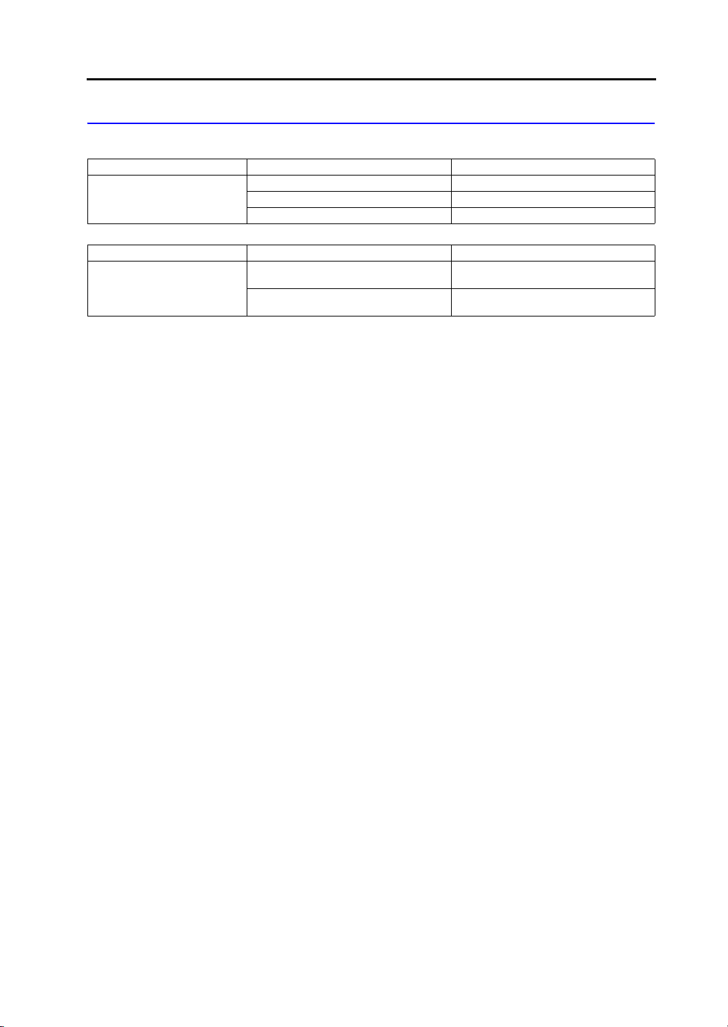
The manuals shown below are related manuals for the V9 series. Refer to them as necessary.
Manual Name Contents Reference No.
V9 Series Reference Manual [1] Explains the functions and operation of the V9
V9 Series Reference Manual [2] 1066NE
V9 Series Setup Manual Explains the installation procedure of V-SFT
V9 Series
Troubleshooting/
Maintenance Manual
V9 Series
Training Manual Beginner’s Guide
V9 Series
Training Manual Practical Guide
V9 Series Macro Reference Provides an overview of macros of V-SFT
V9 Series Operation Manual Explains the configuration of V-SFT version 6,
V9 Series
Connection Manual [1]
V9 Series
Connection Manual [2]
series.
version 6, the creation process of simple screen
programs as well as how to transfer a created
screen program using V-SFT version 6.
Provides an error list and explains the operating
procedures for the V9 series.
Explains the screen creation process using
V-SFT version 6 with examples in detail.
version 6 and explains macro editor operations
and macro command descriptions in detail.
the editing process of each part and limitations
regarding operation in detail.
Explains the connection and communication
parameters for the V9 series and controllers in
detail.
Included Makers
ALLEN BRADLEY, Automationdirect, Azbil,
Baumuller, BECKHOFF, CHINO, CIMON,
DELTA, DELTA TAU DATA SYSTEMS,
EATON Cutler-Hammer, EMERSON,
FANUC, FATEK AUTOMATION, FUFENG,
Fuji Electric, Gammaflux,
GE Fanuc, Hitachi, Hitachi Industrial
Equipment Systems
Explains the connection and communication
parameters for the V9 series and controllers in
detail.
Included Makers
IAI, IDEC, JTEKT, KEYENCE, KOGANEI,
KOYO ELECTRONICS, LS,
MITSUBISHI ELECTRIC, MODICON,
MOELLER, M-SYSTEM, OMRON,
Oriental Motor, Panasonic, RKC, RS
Automation
1065NE
1067NE
1068NE
1069NE
1070NE
1071NE
1072NE
2210NE
2211NE
Page 4
Manual Name Contents Reference No.
V9 Series
Connection Manual [3]
For further details about controllers (PLCs, temperature controllers, etc.), refer to the manual issued by each
controller manufacturer.
Explains the connection and communication
parameters for the V9 series and controllers in
detail.
Included Makers
SAIA, SAMSUNG, SanRex, SANMEI,
SHARP, SHIMADEN, SHINKO TECHNOS,
Siemens, SINFONIA TECHNOLOGY,
TECO, Telemecanique, TOHO, TOSHIBA,
TOSHIBA MACHINE, TURCK, UNIPULSE,
UNITRONICS, VIGOR, WAGO, XINJE,
YAMAHA, Yaskawa Electric, Yokogawa
Electric, MODBUS, Barcode Reader, Slave
Communication Function, Universal Serial
Communication
2212NE
Notes:
1. This manual may not, in whole or in part, be printed or reproduced without the prior written consent of
Hakko Electronics Co., Ltd.
2. The information in this manual is subject to change without prior notice.
3. Windows and Excel are registered trademarks of Microsoft Corporation in the United States and other
countries.
4. All other company names or product names are trademarks or registered trademarks of their
respective holders.
5. This manual is intended to give accurate information about MONITOUCH hardware. If you have any
questions, please contact your local distributor.
Page 5
Types and Model Names of the V9 Series
The MONITOUCH V9 series comprises the following types.
General Name Model Classification Model
Advanced model V910xiW, V9071iW
V9 series
General Name Model Classification Model
V9 series
Note that model names are differentiated according to the above descriptions in this manual for operation
explanations.
Standard model V9120iS, V9100iS, V9080iS
Lite model V9100iC, V9080iC
Additional wired LAN I/F model
Wireless LAN I/F model
V9 model name with “L” added
Example: V9101iWLD
V9 model name with “R” added
Example: V9101iWRLD
Page 6
Notes on Safe Usage of MONITOUCH
DANGER
CAUTION
CAUTION
CAUTION
In this manual, you will find various notes categorized under the following levels with the signal words “DANGER”
and “CAUTION”.
Indicates an imminently hazardous situation which, if not avoided, will result in death or
serious injury.
Indicates a potentially hazardous situation which, if not avoided, may result in minor or
moderate injury and could cause property damage.
Note that there is a possibility that items listed with may have serious ramifications.
DANGER
Never use the output signal of the V9 series for operations that may threaten human life or damage the
system, such as signals used in case of emergency. Please design the system so that it can cope with a
touch switch malfunction. A touch switch malfunction may result in machine accidents or damage.
Turn off the power supply when you set up the unit, connect new cables, or perform maintenance or
inspections. Otherwise, electrical shock or damage may occur.
Never touch any terminals while the power is on. Otherwise, electrical shock may occur.
You must cover the terminals on the unit before turning the power on and operating the unit. Otherwise,
electrical shock may occur.
The liquid crystal in the LCD panel is a hazardous substance. If the LCD panel is damaged, do not ingest the
leaked liquid crystal. If leaked liquid crystal makes contact with skin or clothing, wash it away with soap and
water.
Never disassemble, recharge, deform by pressure, short-circuit, reverse the polarity of the lithium battery,
nor dispose of the lithium battery in fire. Failure to follow these conditions will lead to explosion or ignition.
Never use a lithium battery that is deformed, leaking, or shows any other signs of abnormality. Failure to
follow these conditions will lead to explosion or ignition.
Switches on the screen are operable even when the screen has become dark due to a faulty backlight or
when the backlight has reached the end of its service life. If the screen is dark and hard to see, do not touch
the screen. Otherwise, a malfunction may occur resulting in machine accidents or damage.
Check the appearance of the unit when it is unpacked. Do not use the unit if any damage or deformation is
found. Failure to do so may lead to fire, damage, or malfunction.
For use in a facility or as part of a system related to nuclear energy, aerospace, medical, traffic equipment, or
mobile installations, please consult your local distributor.
Operate (or store) the V9 series under the conditions indicated in this manual and related manuals. Failure
to do so could cause fire, malfunction, physical damage, or deterioration.
Observe the following environmental restrictions on use and storage of the unit. Otherwise, fire or damage to
the unit may result.
- Avoid locations where there is a possibility that water, corrosive gas, flammable gas, solvents, grinding
fluids, or cutting oil can come into contact with the unit.
- Avoid high temperatures, high humidity, and outside weather conditions, such as wind, rain, or direct
sunlight.
- Avoid locations where excessive dust, salt, and metallic particles are present.
- Avoid installing the unit in a location where vibrations or physical shocks may be transmitted.
Page 7
Equipment must be correctly mounted so that the main terminal of the V9 series will not be touched
CAUTION
inadvertently. Otherwise, an accident or electric shock may occur.
Tighten the mounting screw on the fixtures of the V9 series to an equal torque of 0.6 N·m.
Excessive tightening may distort the panel surface. Loose mounting screws may cause the unit to fall down,
malfunction, or short-circuit.
Check periodically that terminal screws on the power supply terminal block and fixtures are firmly tightened.
Loosened screws or nuts may result in fire or malfunction.
Tighten the terminal screws on the power supply terminal block of the V9 series to an equal torque of 7.1 to
8.8 inch-lbf (0.8 to 1.0 N·m). Improper tightening of screws may result in fire, malfunction, or other serious
trouble.
The V9 series has a glass screen. Do not drop the unit or impart physical shocks to the unit. Otherwise, the
screen may be damaged.
Correctly connect cables to the terminals of the V9 series in accordance with the specified voltage and
wattage. Overvoltage, overwattage, or incorrect cable connection could cause fire, malfunction, or damage
to the unit.
Always ground the V9 series. The FG terminal must be used exclusively for the V9 series with the level of
grounding resistance less than 100 . Otherwise, you may sustain an electric shock, a fire may occur,
MONITOUCH may not recognize touch operations, and malfunctions may occur.
Prevent any conductive particles from entering the V9 series. Failure to do so may lead to fire, damage, or
malfunction.
After wiring is finished, remove the paper used as a dust cover before starting operation of the V9 series.
Operation with the dust cover attached may result in accidents, fire, malfunction, or other trouble.
Do not attempt to repair the V9 series yourself. Contact Hakko Electronics or the designated contractor for
repairs.
Do not repair, disassemble, or modify the V9 series. Hakko Electronics Co., Ltd. is not responsible for any
damages resulting from repair, disassembly, or modification of the unit that was performed by an
unauthorized person.
Do not use sharp-pointed tools to press touch switches. Doing so may damage the display unit.
Only experts are authorized to set up the unit, connect cables, and perform maintenance and inspection.
Lithium batteries contain combustible material such as lithium and organic solvents. Mishandling may cause
heat, explosion, or ignition resulting in fire or injury. Read the related manuals carefully and correctly handle
the lithium battery as instructed.
Take safety precautions during operations such as changing settings when the unit is running, forced output,
and starting and stopping the unit. Any misoperations may cause unexpected machine movement, resulting
in machine accidents or damage.
In facilities where the failure of the V9 series could lead to accidents that threaten human life or other serious
damage, be sure that such facilities are equipped with adequate safeguards.
When disposing of the V9 series, it must be treated as industrial waste.
Before touching the V9 series, discharge static electricity from your body by touching grounded metal.
Excessive static electricity may cause malfunction or trouble.
Insert an SD card into MONITOUCH in the same orientation as pictured on the unit. Failure to do so may
damage the SD card or the slot on the unit.
The SD card access LED flashes red when the SD card is being accessed. Never remove the SD card or
turn off power to the unit while the LED is flashing. Doing so may destroy the data on the SD card. Check
that the LED has turned off before removing the SD card or turning off the power to the unit.
Be sure to remove the protective sheet that is attached to the touch panel surface at delivery before use.
Using MONITOUCH with the protective sheet attached may result in incorrect touch switch activation.
When using an analog resistive-film type V9 series unit, do not touch two positions on the screen at the
same time. If two or more positions are pressed at the same time, the switch located between the pressed
positions may be activated.
Page 8

When using a V9 series unit of the capacitive type, observe the following points.
CAUTION
- Use a Class 2 power supply for the 24 VDC power unit. Using MONITOUCH with an unstable power
supply may result in incorrect touch switch activation.
- Capacitive touch panel types support two-point touch operations. If a third point is touched, the touch
operation will be cancelled.
- Capacitive touch panel types are prone to the influence of conductive material. Do not place conductive
material such as metals near the touch panel surface and do not use the panel if it is wet. Otherwise,
malfunctions may occur.
[General Notes]
Never bundle control cables or input/output cables with high-voltage and large-current carrying cables such as
power supply cables. Keep control cables and input/output cables at least 200 mm away from high-voltage and
large-current carrying cables. Otherwise, malfunction may occur due to noise.
When using the V9 series in an environment where a source of high-frequency noise is present, it is
recommended that the FG shielded cable (communication cable) be grounded at each end. However, when
communication is unstable, select between grounding one or both ends, as permitted by the usage
environment.
Be sure to plug connectors and sockets of the V9 series in the correct orientation. Failure to do so may lead to
damage or malfunction.
If a LAN cable is inserted into the MJ1 or MJ2 connector, the device on the other end may be damaged. Check
the connector names on the unit and insert cables into the correct connectors.
Do not use thinners for cleaning because it may discolor the V9 series surface. Use commercially available
alcohol.
If a data receive error occurs when the V9 series unit and a counterpart unit (PLC, temperature controller, etc.)
are started at the same time, read the manual of the counterpart unit to correctly resolve the error.
Avoid discharging static electricity on the mounting panel of the V9 series. Static charge can damage the unit
and cause malfunctions. Discharging static electricity on the mounting panel may cause malfunction to occur
due to noise.
Avoid prolonged display of any fixed pattern. Due to the characteristic of liquid crystal displays, an afterimage
may occur. If prolonged display of a fixed pattern is expected, use the backlight’s auto OFF function.
The V9 series is identified as a class-A product in industrial environments. In the case of use in a domestic
environment, the unit is likely to cause electromagnetic interference. Preventive measures should thereby be
taken appropriately.
[Notes on the LCD]
Note that the following conditions may occur under normal circumstances.
The response time, brightness, and colors of the V9 series may be affected by the ambient temperature.
Tiny spots (dark or luminescent) may appear on the display due to the characteristics of liquid crystal.
There are variations in brightness and color between units.
[Notes on Capacitive Touch Panels]
Touch panel operability may not be optimal if used with dry fingers or skin. In such a case, use a capacitive
stylus pen.
Periodically clean the touch panel surface for optimum touch operations.
When cleaning, take note of the following points.
<When cleaning>
- The panel surface is made of glass. Be sure to clean the surface gently with a cloth or sponge. Otherwise,
you may scratch or damage the glass.
- Take care not to let cleaning detergent to seep into the touch panel unit.
Do not directly apply or spray cleaning detergent on the panel surface.
[Notes on Wireless LAN]
For details regarding supported wireless LAN standards, radio law certifications, and countries where wireless LAN
can be used, refer to the “V9 Series About Wirelss LAN” manual and the “V9 Series Hardware Specifications”
manual provided with the V9 series unit at delivery.
Page 9

Preface
Notes on Safe Usage of MONITOUCH
Chapter 1 Product Outline
1. Features ......................................................................................................... 1-1
2. Models and Peripheral Equipment ................................................................. 1-3
MONITOUCH Models ................................................................................................ 1-3
Lineup ........................................................................................................................ 1-3
Peripheral Equipment ................................................................................................ 1-6
3. System Configuration..................................................................................... 1-9
Configuration for Advanced Models ........................................................................... 1-9
Standard Model Configuration ................................................................................. 1-10
Lite Model Configuration .......................................................................................... 1-11
Chapter 2 Specifications
1. Advanced Model............................................................................................. 2-1
General Specifications ............................................................................................... 2-1
Installation Specifications........................................................................................... 2-2
Display Specifications ................................................................................................ 2-2
Touch Switch Specifications ...................................................................................... 2-2
Wireless LAN Specifications (Only for Wireless LAN I/F Models).............................. 2-3
Interface Specifications.............................................................................................. 2-3
Clock and Backup Memory Specifications ................................................................. 2-4
Screen Configuration Environment ............................................................................ 2-4
Display Function Specifications ................................................................................. 2-4
Function Performance Specifications......................................................................... 2-5
V9101iW External Dimensions and Panel Cut-out Dimensions................................. 2-6
V9100iW External Dimensions and Panel Cut-out Dimensions................................. 2-7
V9071iW External Dimensions and Panel Cut-out Dimensions................................. 2-8
V9071iW with DUR-00 External Dimensions and Panel Cut-out Dimensions ........... 2-9
2. Standard Model ............................................................................................ 2-10
General Specifications ............................................................................................. 2-10
Installation Specifications......................................................................................... 2-11
Display Specifications .............................................................................................. 2-11
Touch Switch Specifications .................................................................................... 2-12
Wireless LAN Specifications (Only for Wireless LAN I/F Models)............................ 2-12
Function Switch Specifications................................................................................. 2-12
Interface Specifications............................................................................................ 2-12
Clock and Backup Memory Specifications ............................................................... 2-13
Screen Configuration Environment .......................................................................... 2-13
Display Function Specifications ............................................................................... 2-14
Function Performance Specifications....................................................................... 2-15
V9120iS External Dimensions and Panel Cut-out Dimensions................................ 2-16
V9100iS External Dimensions and Panel Cut-out Dimensions................................ 2-17
Contents
Page 10

V91080iSD External Dimensions and Panel Cut-out Dimensions ........................... 2-18
3. Lite Model..................................................................................................... 2-19
General Specifications ............................................................................................. 2-19
Installation Specifications......................................................................................... 2-20
Display Specifications .............................................................................................. 2-20
Touch Switch Specifications .................................................................................... 2-20
Function Switch Specifications................................................................................. 2-20
Interface Specifications............................................................................................ 2-21
Clock and Backup Memory Specifications ............................................................... 2-22
Screen Configuration Environment .......................................................................... 2-22
Display Function Specifications ............................................................................... 2-22
Function Performance Specifications....................................................................... 2-23
V9100iC External Dimensions and Panel Cut-out Dimensions................................ 2-24
V9080iCD External Dimensions and Panel Cut-out Dimensions ............................. 2-25
Chapter 3 Names and Specifications of Components
1. Names and Functions of Components ........................................................... 3-1
Advanced Model ........................................................................................................ 3-1
Standard Model.......................................................................................................... 3-5
Lite Model .................................................................................................................. 3-8
2. Specifications of Components...................................................................... 3-10
Serial Connector (CN1)............................................................................................ 3-10
Modular Jack (MJ1/MJ2).......................................................................................... 3-11
USB-A (Master Port) ................................................................................................ 3-13
USB mini-B (Slave Port)........................................................................................... 3-17
LAN Connector (LAN) .............................................................................................. 3-18
Additional LAN Connector (LAN2) (Only for Additional Wired LAN I/F Models) ...... 3-19
Connector for Wireless LAN Dipole Antenna (WLAN)
(Only for Wireless LAN I/F Models).......................................................................... 3-20
Communication Interface Unit Connector (EXT1).................................................... 3-23
Optional Unit Connector (EXT2) (V910xiW/Standard Models Only) ........................ 3-24
SD Card Interface (SD) ............................................................................................ 3-25
Audio Output Connector (AUDIO) (V910xiW/Standard Models Only) ..................... 3-27
DIP Switches (DIPSW)............................................................................................. 3-28
Chapter 4 Installation
1. Installation Procedure..................................................................................... 4-1
Installation Procedure ................................................................................................ 4-1
Installation Conditions ................................................................................................ 4-3
2. Power Supply Cable and Grounding Connections ......................................... 4-5
Power Supply Cable Connection ............................................................................... 4-5
Notes on Usage of the 100 to 240 VAC Specification................................................ 4-6
Grounding .................................................................................................................. 4-6
3. Securing USB Cables..................................................................................... 4-7
4. Inserting and Removing SD Cards................................................................. 4-8
SD Card Insertion/Removal Procedure...................................................................... 4-8
Page 11

5. Installing the Battery....................................................................................... 4-9
Role of the Battery ..................................................................................................... 4-9
Battery Replacement Period ...................................................................................... 4-9
Battery Voltage Drop Detection.................................................................................. 4-9
Battery Replacement ................................................................................................. 4-9
Notes on the Battery: EU Directive 2006/66/EC ...................................................... 4-14
Chapter 5 Inspection and Maintenance
1. Inspection and Maintenance .......................................................................... 5-1
Daily Inspection.......................................................................................................... 5-1
Periodical Inspection .................................................................................................. 5-1
2. Warranty Policy .............................................................................................. 5-2
Inquiries about Failure ............................................................................................... 5-2
Warranty Period ......................................................................................................... 5-2
Free-of-charge Repair................................................................................................ 5-2
Chargeable Repair ..................................................................................................... 5-2
Inquiry Form ............................................................................................................... 5-3
Page 12

1
1. Features
2. Models and Peripheral Equipment
3. System Configuration
Product Outline
Page 13

1. Features 1-1
1. Features
The V9 series inherits and improves on the features of the V8 series as described below.
1. A programmable display unit that offers 16.77 million maximum display colors* and an LCD with an
LED backlight.
V9 series units are divided into the following model types.
* Only for displaying “picture” images and 3D parts. All other content is displayed using 65,536 colors.
Advanced model:
A high-definition/resolution and high-performance model standardly equipped with a wide
high-resolution LCD, two wired LAN connectors, and connectors for communication interface
units. Capacitive touch panel types are also available.
Standard model:
A high-performance model equipped with connectors for communication interface units,
connectors for optional units, and an audio output connector as standard.
Lite model:
A basic model that does not include the connectors for optional units or the audio output
connector.
2. Improved performance
High-speed processing and rapid rendering can be achieved through the adoption of a
high-performance processor and significantly increased CPU clock speed.
3. LAN connectors standard on all models
All models are equipped with LAN connectors (10BASE-T/100BASE-TX).
The Advanced model is equipped with two LAN connectors as standard.
4. SD card interface as standard
All models are equipped with an SD/SDHC card interface as standard.
SD cards can be used as storage for saving screen programs and logging/alarm data, and
transferring recipe data.
5. Wireless LAN function as standard
Models are equipped with a wireless LAN function compliant with IEEE802.11b/g/n as standard.
An access point is built-in, allowing direct communication with devices equipped with wireless LAN
function such as tablets.
* Only for wireless LAN I/F models
6. Scrolling function
Single screens can be registered at sizes higher than the resolution of the display unit and the
scrolling function can be used to display each part of such screens.
According to screen configuration, this function can be used to display screens of sizes that extend
in the horizontal and vertical directions.
In addition, navigation display is supported which allows users to instantly check the current
display position.
7. Zoom in/out function
Screens can be zoomed in by a maximum of 200 % using pinch-in and pinch-out gestures.
This enables users to check parts that are small and difficult to see.
* Only for Advanced models. Standard and Lite models can be zoomed in/out by double-tapping.
8. VNC server function
All models can be remotely monitored and operated from a computer or tablet.
Server functions can be limited to remote monitoring as necessary.
9. VPN function
All models are equipped with a VPN function, enabling safe, simple and low-cost VPN
communication.
For 2CH/3CH LAN types, the routing function can be used to establish remote connection to
devices connected to the V9 series unit via Ethernet, such as a PLC and network camera.
1
Product Outline
Page 14

1-2 1. Features
10. Scheduler function
Predetermined operations (turning bits ON, executing macros, etc.) can be executed at a time set
in advance, such as every week, every day, or a specified time. Operations such as periodical
saving of logging/alarm data can be scheduled easily.
11. TrueType font
TrueType fonts enable smoother character expression through anti-aliasing processing.
Page 15
2. Models and Peripheral Equipment 1-3
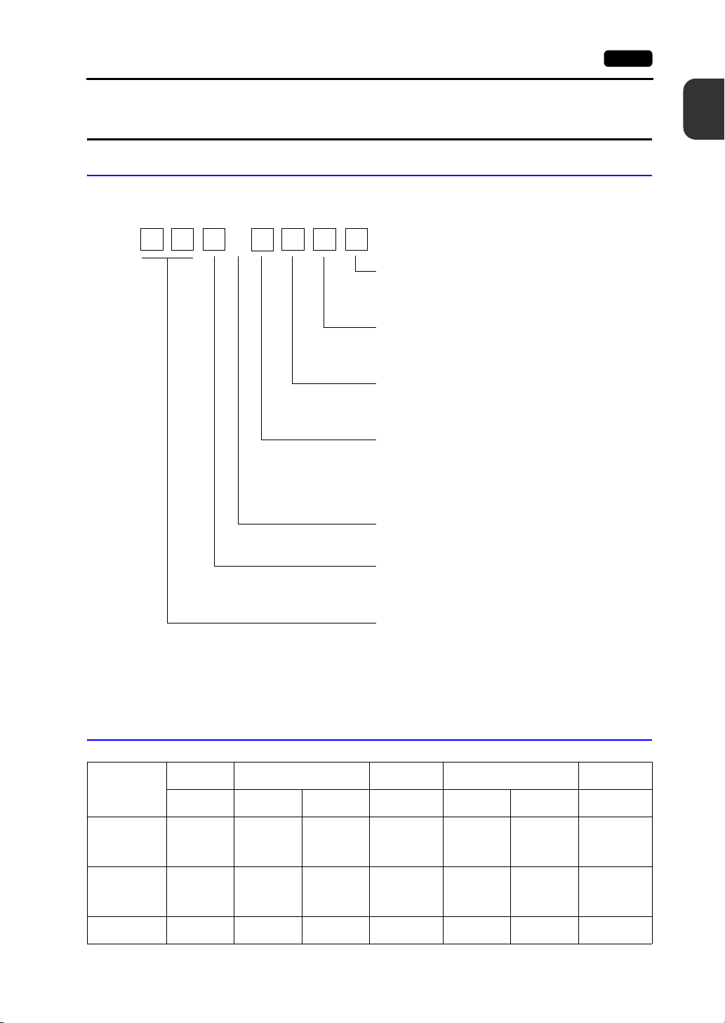
Power supply specification
None: 100 to 240 VAC type
D: 24 VDC type
Additional wired LAN I/F
None: No additional wired LAN I/F
L: With additional wired LAN I/F
Wireless LAN I/F
None: No wireless LAN I/F
R: With wireless LAN I/F
Device specification
W: TFT color LCD (WSVGA: V910xiW)
(WVGA: V9071iW)
S: TFT color LCD (SVGA)
C: TFT color LCD (VGA)
Functional specification
i: With built-in LAN port
Touch switch specification
0: Analog resistive film type
1: Capacitive type
Screen size
12: 12.1-inch
10: 10.4-inch (Standard/Lite models)
10.1-inch, widescreen (Advance models)
08: 8.4-inch
07: 7.0-inch widescreen
V9 i
2. Models and Peripheral Equipment
MONITOUCH Models
The model name consists of the following information.
1
Product Outline
Lineup
Model
Advanced - - -
Standard
Lite - -
12.1-inch 10.4-inch
SVGA
(800 600)
SVGA
(800 600)
V9120iS
V9120iSD
V9120iSLD
V9120iSRD
V9100iS
V9100iSD
V9100iSLD
V9100iSRD
VGA
(640 480)
--
V9100iC
V9100iCD
10.1-inch
Widescreen
WSVGA
(1024 600)
V9101iWRLD
V9100iWRLD
V9101iWLD
V9100iWLD
SVGA
(800 600)
V9080iSD
V9080iSLD
V9080iSRD
- - V9080iCD -
8.4-inch
VGA
(640 480)
--
--
7.0-inch
Widescreen
(800 480)
V9071iWRLD
V9071iWLD
WVGA
Page 16
1-4 2. Models and Peripheral Equipment
Advanced Model
A high-definition/resolution and high-performance model standardly equipped with a wide
high-resolution LCD, two wired LAN connectors, and connectors for communication interface units.
Capacitive touch panel types are also available.
Unit specifications
Model
V9101iWRLD
V9100iWRLD
V9101iWLD Capacitive type
V9100iWLD
V9071iWRLD
V9071iWLD Capacitive type
External I/F
Model
V9101iWRLD
V9100iWRLD
V9101iWLD
V9100iWLD
V9071iWRLD
V9071iWLD
Display Device Resolution Touch Switch
10.1-inch
Widescreen
7.0-inch
Widescreen
Communication
I/F Unit
Unit Specifications
Capacitive type
Analog resistive
1024 600
dots
800 480
dots
Optional
Units
film type
Analog resistive
film type
Capacitive type
Audio Output Wireless LAN
Power Supply
Type
DC power
supply
Standards
CE/KC/
UL/cUL
Additional
Wired LAN
Standard Model
A high-performance model equipped with connectors for communication interface units, connectors for
optional units, and an audio output connector as standard.
Unit specifications
V9120iS
V9120iSD
V9120iSLD
V9120iSRD UL/cUL
V9100iS
V9100iSD
V9100iSLD
V9100iSRD UL/cUL
V9080iSD
V9080iSLD
V9080iSRD UL/cUL
Model
Unit Specifications
Display Device Resolution Touch Switch
12.1-inch
10.4-inch
8.4-inch
800 600
dots
Analog resistive
film type
Power Supply
Type
AC power
supply
DC power
supply
AC power
supply
DC power
supply
Standards
KC
CE/KC/
UL/cUL
KC
CE/KC/
UL/cUL
CE/KC/
UL/cUL
Page 17
2. Models and Peripheral Equipment 1-5
Lite Model
External I/F
Model
V9120iS
V9120iSD
V9120iSLD
V9120iSRD
V9100iS
V9100iSD
V9100iSLD
V9100iSRD
V9080iSD
V9080iSLD
V9080iSRD
Communication
I/F Unit
Optional
Units
Audio Output Wireless LAN
Additional
Wired LAN
A basic model that does not include the connectors for optional units or the audio output connector.
Unit specifications
Model
V9100iC
V9100iCD
V9080iCD 8.4-inch
Display Device Resolution Touch Switch
10.4-inch
Unit Specifications
640 480
dots
Analog resistive
film type
Power Supply
Type
AC power
supply
DC power
supply
Standards
KC
CE/KC/
UL/cUL
1
Product Outline
External I/F
Model
V9100iC
V9100iCD
V9080iCD
Communication
I/F Unit
Optional
Units
Audio Output Wireless LAN
Additional
Wired LAN
Page 18
1-6 2. Models and Peripheral Equipment
FG
CN1
T1
T2
SD
x10
x1
Peripheral Equipment
The following software and equipment are available as options for the V9 series.
Drawing Tool
V-SFT-6 (configuration software)
Application software for editing MONITOUCH screen programs.
Supported OS:
Windows XP, XP 64 Edition, Vista (32-bit, 64-bit), 7 (32-bit, 64-bit), 8 (32-bit, 64-bit) /
8.1 (32-bit, 64-bit)
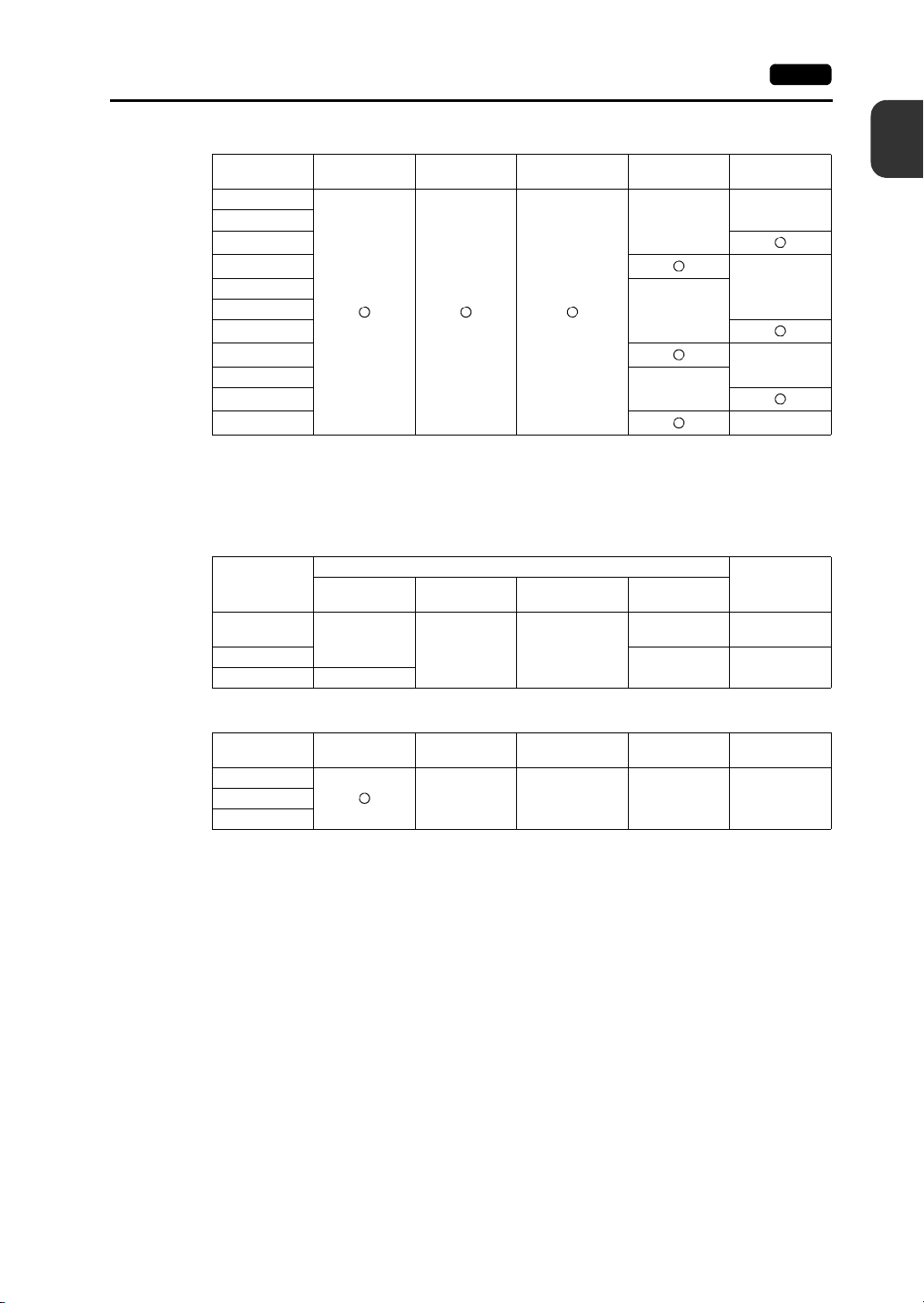
V-CP (screen program transfer cable) 3 m
A cable used for connecting the V9 series unit to a computer.
Optional Units
GUR-xx
Optional units for the V910xiW and Standard models.
GUR-01 RGB input 1CH
GUR-02 RGB output 1CH
GUR-04 Video input 1CH
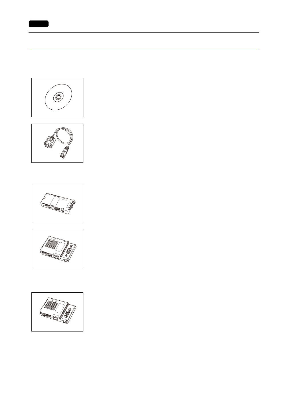
DUR-00
Optional unit for the V9071iW.
Supports D-sub 9-pin connectors.
* This unit cannot be used together with a “CUR-xx” communication interface unit.
Communication Interface Unit
CUR-xx
Communication units used for connecting to networks.
* These units cannot be used together with the optional “DUR-00” unit.
CUR-00 OPCN-1
CUR-01 T-Link
CUR-02 CC-Link (under development)
CUR-03 Ethernet
CUR-04 PROFIBUS-DP (under development)
CUR-06 SX-BUS
CUR-07 DeviceNet (under development)
CUR-08 FL-net
Page 19
2. Models and Peripheral Equipment 1-7
Cables
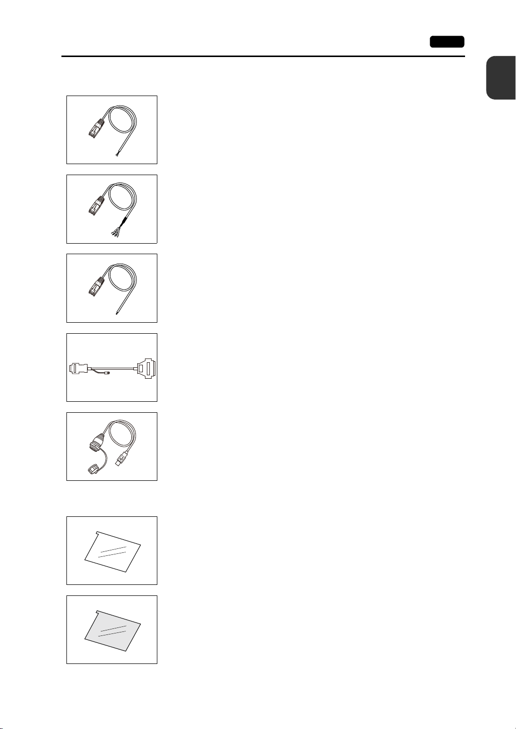
V6-BCD (barcode reader connection cable) 3 m
A cable used for connecting a barcode reader unit to the V9 series.
V6-MLT (multi-link2 master cable) 3 m
A cable used for multi-link2 connection between a V9 master station and V9 slave station.
V6-TMP (connection cable for controllers)
A cable used for connecting the V9 series unit to a controller.
V6-TMP: 3 m
V6-TMP-5M: 5 m
V6-TMP-10M: 10 m
D9-D25 (D-sub 9-pin-to-25-pin conversion cable) 0.3 m
A conversion cable used for connecting the communication cable for the CN1 (D-sub 25-pin)
of the V6/V7 series to the CN1 (D-sub 9-pin) of the V9 series.
1
Product Outline
Protective Sheets
UA-FR (for USB-A port) 1 m
A cable for USB-A (master) that allows connection from the front of the control cabinet.
V9xxx-GS
A sheet used for protecting the operation panel surface (5 pcs./set).
V912S-GS V9120 series
V910S-GS V9100 series
V910W-GS V9100iW (analog resistive film type touch panel) *
* This sheet cannot be used for the V9101iW (capacitive type touch panel).
V908S-GS V9080 series
V9xxx-GSN10
A sheet used for protecting the operation panel surface (5 pcs./set, anti-glare treatment).
The sheet is colored light gray and the graininess on its surface prevents light reflection.
V912S-GSN10 V9120 series
V910S-GSN10 V9100 series
V910W-GS V9100iW (analog resistive film type touch panel) *
* This sheet cannot be used for the V9101iW (capacitive type touch panel).
V908S-GSN10 V9080 series
Page 20
1-8 2. Models and Peripheral Equipment
+5V
SG
+SD
-SD
+RD
-RD
FG
GD
GPP
V
-
M
D
D
1 2 3
Under development
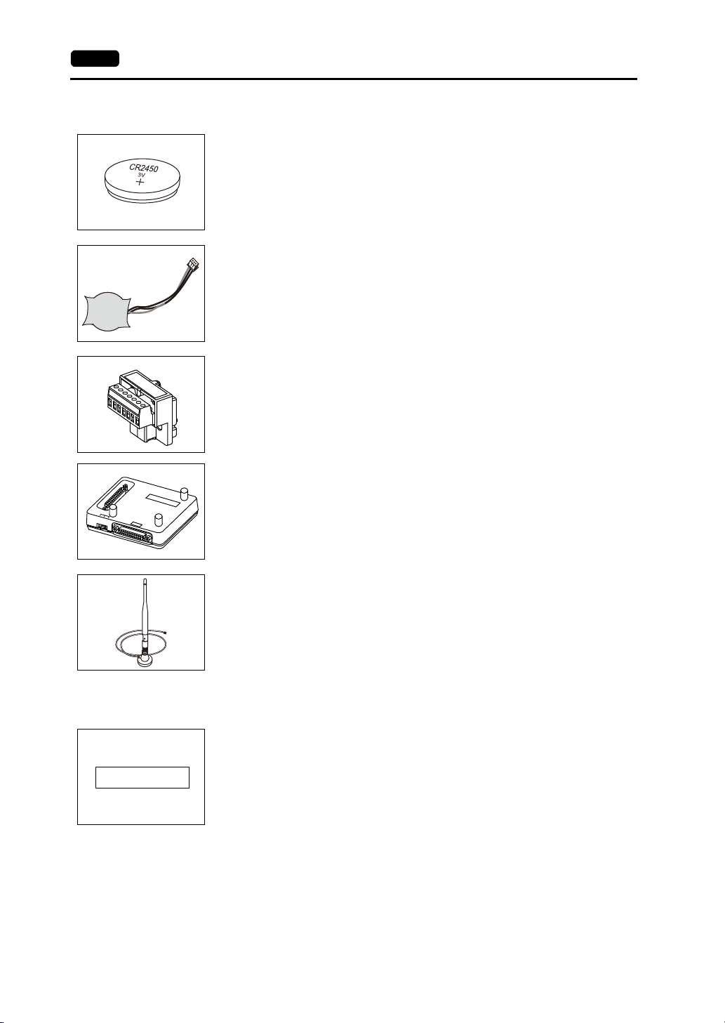
Other Options
V9-BT (replacement battery)
A replacement lithium battery for the V9120/V9100/V910xiW/V9080 series (CR2450S
manufactured by Sony Energy Devices).
V7-BT (replacement battery)
A replacement lithium battery for the V9071iW series.
TC-D9 (terminal converter)
This converter is used for connection between the V9 series unit and a controller at the
RS-422/485 terminal block via CN1 (D-sub 9-pin).
V-MDD (ACPU/QnACPU/FXCPU dual port interface)
An add-on connector with two ports and specifically designed for the connector on
MITSUBISHI ACPU/QnACPU/FXCPU controllers. It is convenient to use this connector
when directly connecting the V9 series unit to a ACPU/QnACPU/FXCPU controller.
V9-ANT (external dipole antenna for wireless LAN)
An external dipole antenna (3 m) for V9 series units that support wireless LAN.
Card Recorder (under development)
USB-CFREC-2 (USB CF card recorder)
A unit that connects to the USB-A port and enables use of CF cards.
Page 21
3. System Configuration 1-9
KEYPAD
CONTROL
P
R
O
MO
DE
Hz
KW
A
RUN
STOP
PRG
RE
S
ET
FUNC
D
A
T
A
Inverter
Ethernet
USB
LAN/LAN2
V9
“V-SFT-6”
“V-CP”
“V6-BCD”
“V6-TMP”
USB-A
MJ1
CN1
Ethernet
PictBridge
AUDIO
LAN/LAN2WLAN
*1
*1
*4
*2
*3
MJ1/MJ2
SD
USB mini-B
V9
V9
V9 series screen
configuration
software
Screen
creation
Screen program transfer
Printer
Barcode reader
Temperature
controller, inverter
Printer (PictBridge)
Video camera
(video input)
Computer
(RGB input)
PLC/
general purpose computer
Computer (PC)
Display
(RGB output)
Speaker
(audio output)
PLC
Temperature controller, inverter
Barcode reader
Barcode reader
Mouse
Keyboard
USB flash drive
Screen program
transfer
Screen
program
transfer
PLC
Network camera
Serial
Optional unit
Communication
cables
Wireless LAN
Printer
Computer (PC)
Ta bl et
SD card
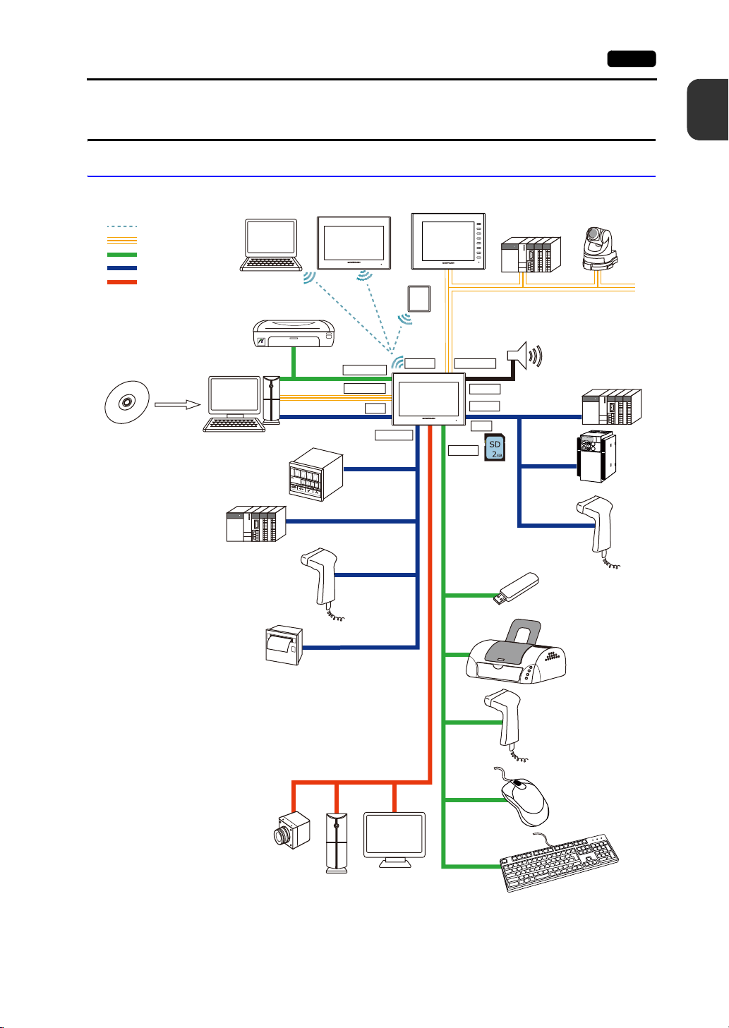
3. System Configuration
Configuration for Advanced Models
The following figure shows the possible system configurations when using the Advanced model.
1
Product Outline
*1 Only for wireless LAN I/F models.
*2 Only for V910xiW.
*3 For the V9071iW, the optional “DUR-00” unit is required.
*4 Only for V910xiW. The optional “GUR-xx” unit is required.
Page 22
1-10 3. System Configuration
Ethernet
USB
KEYPAD
CONTROL
PRO M
O
DE
Hz
KW
A
RUN
STOP
PRG
R
E
S
ET
FUNC
D
A
T
A
Inverter
V9
“V-SFT-6”
“V-CP”
“V6-BCD”
“V6-TMP”
USB-AMJ1/MJ2
MJ1
LAN
CN1
Ethernet
PictBridge
V9
*1
AUDIO
USB mini-B
SD
V9 series screen
configuration
software
Screen
creation
Screen program
transfer
Printer
Barcode reader
Temperature
controller, inverter
Computer (PC)
Video camera
(video input)
Computer
(RGB input)
PLC/
general purpose
computer
Computer (PC)
Display
(RGB output)
Speaker
(audio output)
PLC
Temperature controller, inverter
Barcode reader
Barcode reader
Mouse
Keyboard
USB flash drive
Screen
program
transfer
Screen program transfer
PLC
Network camera
Serial
Optional unit
Communication
cables
Printer (PictBridge)
Printer
SD card
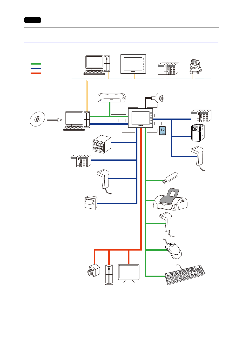
Standard Model Configuration
The following figure shows the possible system configurations when using the Standard model.
*1 The optional “GUR-xx” unit is required.
Page 23
3. System Configuration 1-11
V9 series screen
configuration
software
Screen
creation
Screen program
transfer
Printer
Barcode reader
Temperature
controller, inverter
Computer (PC)
PLC/
general purpose
computer
Computer (PC)
PLC
Temperature controller, inverter
Barcode reader
Barcode reader
Mouse
Keyboard
USB flash drive
Screen
program
transfer
Screen program transfer
PLC
Network camera
Serial
Communication
cables
Printer (PictBridge)
Printer
SD card
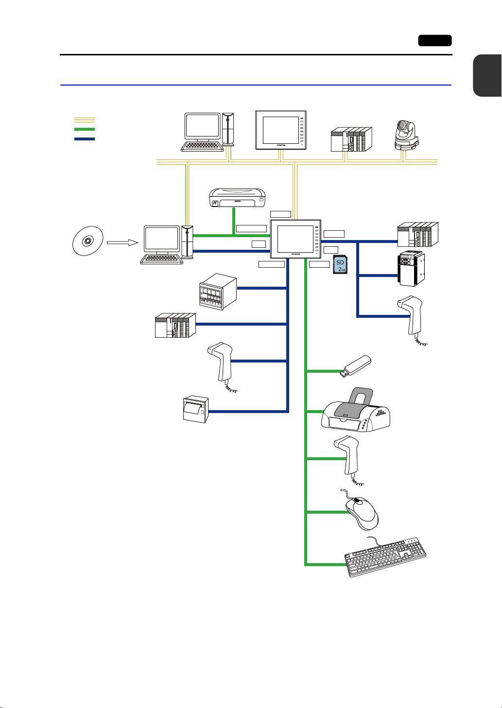
Lite Model Configuration
The following figure shows the possible system configurations when using the Lite model.
Ethernet
USB
“V-SFT-6”
1
Product Outline
V9
Ethernet
PictBridge
LAN
USB mini-B
“V-CP”
MJ1
V9
“V6-TMP”
“V6-BCD”
CN1
SD
USB-AMJ1/MJ2
KEYPAD
Hz
C
ONTROL
A
P
R
O
MOD
E
KW
PRG
R
E
S
E
T
RUN
FUNC
D
A
T
A
STOP
Inverter
Page 24

1-12 3. System Configuration
Please use this page freely.
Page 25

2
1. Advanced Model
2. Standard Model
3. Lite Model
Specifications
Page 26
1. Advanced Model
+0.50+0.50+0.50+0.5
0
1. Advanced Model 2-1
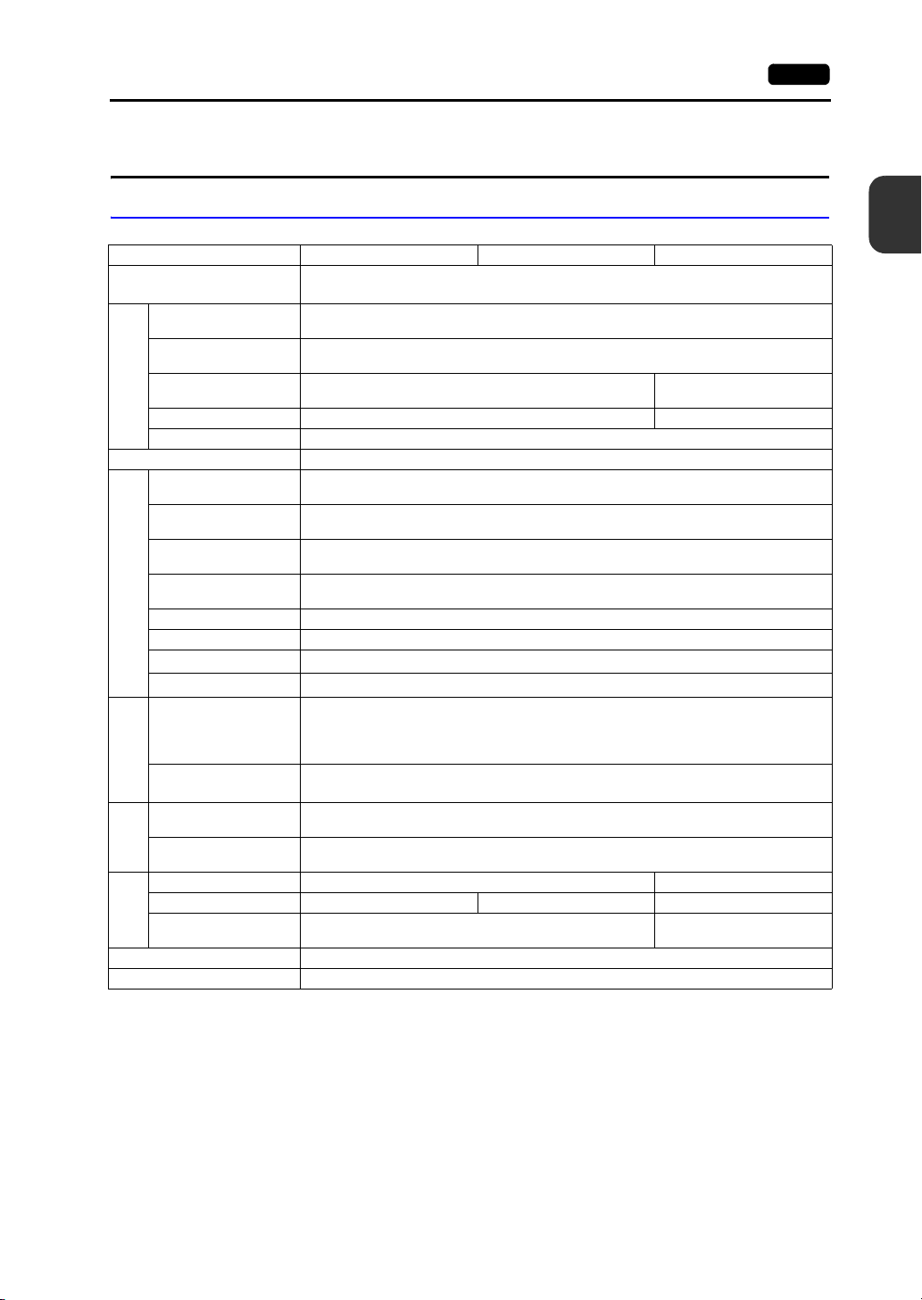
General Specifications
Item V9101iW V9100iW V9071iW
Conformance Standards
Permissible Voltage
Range
Permissible Momentary
Power Failure
Power Consumption
(Max. Rating)
Power Supply
Rush Current 17 A or less, 6 ms 12 A or less, 5 ms
Withstand Voltage DC external terminals to FG: 500 VAC for 1 minute
Insulation Resistance DC external terminals to FG: 500 VDC, 10 M or higher
Operational Ambient
Temperature
Storage Ambient
Temperature
Operational Ambient
Humidity
Storage Ambient
Humidity
Altitude 2000 m or less
Physical Environment
Atmosphere No corrosive gas, no excessive dust, and no conductive dust
Overvoltage Category
Contamination Level
Vibration Resistance
Working
Conditions
Mechanical
Shock Resistance
Noise Resistance
Static Electricity
Working
Electrical
Conditions
Discharge Resistance
Weight Approx. 1.7 kg Approx. 1.0 kg
Dimensions W H D 278.5 198.5 54.4 mm 278.5 198.5 53.2 mm 201.6 147.6 60.3 mm
Panel Cut-out
Mounting
Conditions
Dimensions
Case Color Light gray
Material PC resin
*1 This product complies with the following radio laws:
Japanese Radio Law: Technical Regulations Conformity Certification, Article 2, clause 1-19
FCC Part15 SubPart C
IC RSS210,Gen
R&TTE: EN300328, EN301489-1, EN301489-17, EN62311, EN60950-1
KC
The product will not conform to the above laws if using any antenna other than the built-in antenna of the V9
series unit or the optional V9-ANT for wireless LAN connection.
*2 Use the unit in an environment where the wet-bulb temperature is 39 C or less, otherwise the unit may be
damaged.
*3 This indicates the distribution section to which the unit is intended to be connected to within the path between
the distribution of the public power network and machinery in the facility.
“Category II” applies to devices supplied with power from mains sockets or similar points. The withstand surge
voltage is 2,500 V for devices rated up to 300 V.
Radio laws (Japan: TELEC, USA: FCC, Canada: IC RSS, Europe: R&TTE, South Korea: KC)
*3
*4
Vibration frequency: 5 to 9 Hz, Half-amplitude: 3.5 mm, Vibration frequency: 9 to 150 Hz,
Peak acceleration: 147 m/s
KC, CE (EN61000-6-2, EN61000-6-4), UL508,
24 VDC 10 %
Within 1 ms
27 W or less 22 W or less
0 °C to +50 °C
10 °C to +60 °C
85 % RH or less (without dew condensation)
85 % RH or less (without dew condensation)
Category II
Contamination level 2
JIS B 3502 (IEC61131-2) compliant
Constant acceleration: 9.8 m/s
X, Y, and Z: 3 directions (10 times each)
JIS B 3502 (IEC61131-2) compliant
2
(15 G), X, Y, and Z: 3 directions, 3 times each (18 times in total)
Noise voltage: 1000 Vp-p, Pulse width: 1 s, Rising time: 1 ns
257.0 183.0 mm 187.2 133.4 mm
(Measured using a noise simulator)
Compliant with IEC61000-4-2, contact: 6 kV, air: 8 kV
*2
*2
*2
*2
2
(1 G),
2
*1
Specifications
Page 27
2-2 1. Advanced Model
*4 This is an index that expresses the degree of conductive contamination in the environment where the unit is
used.
“Contamination level 2” indicates the conditions where only non-conductive contamination occurs. However,
due to condensation, temporary conductive contamination may occur.
Installation Specifications
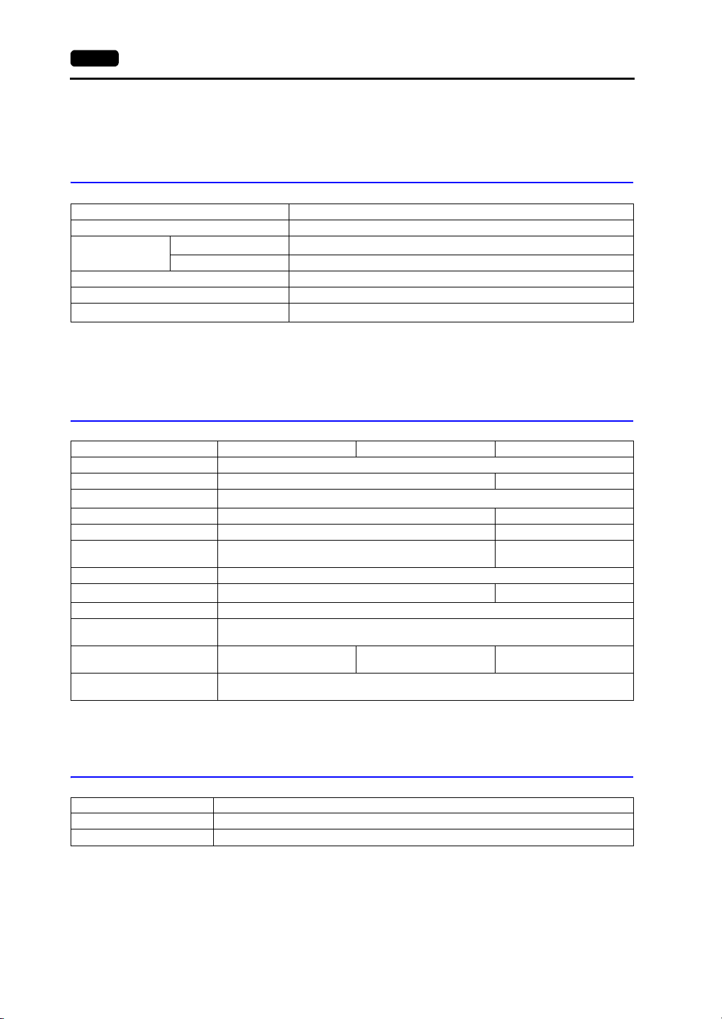
Item Specification
Grounding Less than 100 , FG/SG separated
*1
Protection Structure
Cooling System Natural cooling
Structure Inserted in a mounting panel
Appropriate Mounting Panel Thickness
Panel Front Surface
Rear Case Complies with IP20
*1 Protective structure for the front when the V9 series unit is mounted on a mounting panel.
While the protective structure has passed compliance testing, it is not guaranteed under all environments.
*2 Even when the mounting panel thickness is within the specified range, the panel itself may warp depending on
the material and size of the mounting panel.
Use a panel that can withstand the forces of mounting.
Complies with IP66, with waterproof gasket
1.5 to 4 mm
*2
Display Specifications
Item V9101iW V9100iW V9071iW
Display Device TFT color
Display Size 10.1-inch widescreen 7.0-inch widescreen
Colors
Resolution (W H) 1024 600 dots 800 480 dots
Dot Pitch (W H) 0.2175 0.2088 mm 0.1905 0.1905 mm
Actual Display Dimensions
(W H)
Backlight LED
Backlight Brightness Halftime
Backlight Auto OFF Function Always ON, custom setting
Brightness Adjustment
Touch Panel Operation Surface
POWER Lamp
*1 Only for displaying “picture” images, 3D parts and video images. All other content is displayed using 65,536
colors.
*2 Time until the surface brightness becomes 50 % of the initial value at an ambient temperature of 25 C.
16.77 million colors
222.72 125.28 mm 152.4 91.44 mm
*2
Approx. 50,000 hours Approx. 100,000 hours
System menu: 16 levels
Macro: 128 levels
Touch panel
(Glass)
On: Normal (green)
Flashing: Circuit board or power supply failure
*1
Surface sheet
(PET, 0.188 mm)
Touch panel
(Glass)
Touch Switch Specifications
Item Specification
Type Projected-capacitive type
Surface Treatment Clear
Page 28
1. Advanced Model 2-3
Wireless LAN Specifications (Only for Wireless LAN I/F Models)
Item Specification
Complying Antennas
* For details of other wireless LAN specifications, refer to P 3-20.
Built-in antenna of the V9 series unit
V9-ANT (optional): External dipole antenna for wireless LAN
Interface Specifications
Item Specification
Applicable
standards
Synchronization Asynchronous type
Data Length 7 or 8 bits
*1
D-sub 9-pin (CN1)
Modular Jack, 8-pin
(MJ1, MJ2
Modular Jack, 8-pin
(MJ2
USB Connector
(U-A, U-B)
Ethernet Port
100BASE-TX /
10BASE-T
(LAN, LAN2)
Connector for Wireless LAN Dipole
Antenna (WLAN)
SD Card Interface SD/SDHC card compliant
Communication Interface Unit Connector
(EXT1)
Connector for Optional Unit
(EXT2)
Audio Output Connector (AUDIO)
*3
)
*4
)
*3
Parity None, even, odd
Stop Bit 1 or 2 bits
Baud Rate
Applications PLC, temperature controller, barcode reader connection, etc.
Applicable
standards
Applications
Applicable
standards
Baud Rate
Applications PLC, temperature controller, barcode reader connection, etc.
Applicable
standards
Baud Rate High speed 480 Mbps
USB-A
Applications
Applicable
standards
Baud Rate High speed 480 Mbps
Applications Screen program transfer, PictBridge-compatible printer connection
USB mini-B
Applicable
standards
Baud Rate 100 Mbps, 10 Mbps
Protocol TCP/IP, UDP/IP
Functions Auto-MDIX, Auto-Negotiation
Recommended
*5
Cable
Applications Screen program transfer, PLC connection, etc.
*6
*3
RS-232C, RS-422/485
4800, 9600, 19200, 38400, 57600, 76800, 115k bps
(For PPI/MPI connection with a Siemens PLC: 187.5 kbps
RS-232C, RS-485 (2-wire connection)
Screen program transfer (MJ1), PLC, temperature controller, barcode reader,
printer, multi-link2, V-Link connection, etc.
RS-232C, RS-485 (2-wire connection), RS-422 (4-wire connection)
4800, 9600, 19200, 38400, 57600, 76800, 115k bps
(For PPI/MPI connection with a Siemens PLC: 187.5 kbps
Compliant with USB version 2.0
Printer (EPSON ESC/P-R driver), USB flash drive, USB-CFREC-2 (under
development), keyboard, mouse connection, etc.
Compliant with USB version 2.0
IEEE802.3u compliant (100BASE-TX), IEEE802.3 compliant (10BASE-T)
100 UTP (unshielded twist-pair) cable, category 5, max. 100 m long
Reverse polarity SMA jack
*4
Optional unit “DUR-00”
PROFIBUS-DP, DeviceNet, FL-net connection
* The separate communication interface unit “CUR-xx” (some types currently
under development) is required.
RGB input/output, video input function
* The optional “GUR-xx” unit (under development) is required.
3.5 mm stereo mini jack
, SX-BUS, OPCN-1, T-Link, Ethernet, CC-Link,
*2 *3
*2
)
)
2
Specifications
Page 29
2-4 1. Advanced Model
*1 For the V9071iW, the optional “DUR-00” unit must be attached.
*2 For details, refer to the V9 Series Connection Manual.
*3 Only for V910xiW.
*4 Only for V9071iW.
*5 Both straight and cross cables are usable, irrespective of the presence or absence of a hub.
*6 Only for wireless LAN I/F models.
Clock and Backup Memory Specifications
Item V910xiW V9071iW
Battery
Backup Memory SRAM 800 KB
Backup Retention Period Approx. 5 years (ambient temperature at 25 C)
Battery Voltage Drop Detection Provided (allocated to internal device memory address $s167)
Calendar Accuracy *
* When using the unit at an ambient temperature other than 25 C, clock deviation may increase. Check and
correct the clock periodically.
Coin-type lithium primary cell
(CR2450S manufactured by Sony Energy
Devices)
When powered: Monthly deviation of 210 sec. (ambient temperature at 25 C)
When unpowered: Monthly deviation of 90 sec. (ambient temperature at 25 C, with
battery backup)
Coin-type lithium primary cell
(V7-BT manufactured by Hakko
Electronics)
Screen Configuration Environment
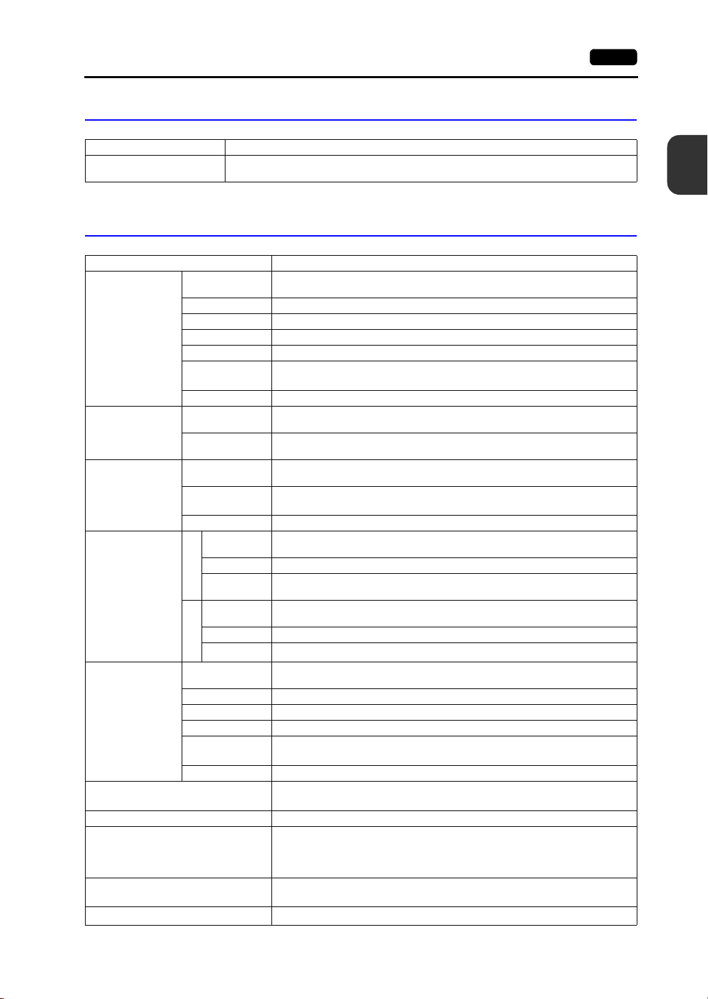
Item Specification
Configuration Method Dedicated configuration software
Name of dedicated configuration software: V-SFT-6
Computer: Pentium IV 2.0 GHz or above recommended
*1
: Windows XP/ XP64 Edition/ Vista(32bit,64bit) / 7 (32bit, 64bit) /
Configuration Tool
*1 Administrator privileges are required for installation.
OS
Memory: 1.0 GB or above (2.0 GB or above recommended)
Hard disk capacity: Free space of approx. 2.0 GB or more
Optical disc drive: DVD-ROM drive
Display: Resolution of 1024 768 or above
Other: Microsoft .NET Framework 4.0 or 4.5
8 (32bit, 64bit) / 8.1 (32bit, 64bit)
Color depth of 16-bit or above
(If a PC does not have .NET Framework 4.0 or 4.5 installed,
Framework 4.0 will be automatically installed on the PC.)
Display Function Specifications
Item Specification
Interface Language
Font Types TrueType fonts, bitmap fonts, Windows fonts
Character
Properties
Graphics
Graphic
Properties
*1
Display Properties Normal, blink, bold, shadow, transparent, italic
Colors 65,536 colors (without blinking) / 32,768 colors (with blinking)
Lines Line, continuous line, box, parallelogram, polygon
Circles Circle, arc, sector, ellipse, elliptical arc
Others Pattern, image, data display (graphics library, data sheets)
Line Types
Tile Patterns 16 types (including 8 user-definable patterns)
Display Properties Normal, blinking
Colors 65,536 colors (without blinking) / 32,768 colors (with blinking)
Color Selection Foreground, background, boundary (line)
*1 For more information, refer to V9 Series Reference Manual 1.
Japanese, English/Western Europe, Chinese (Traditional), Chinese (Simplified), Korean,
6 types (thin, thick, dotted, chain, dashed, two-dot chain)
Line thickness can be selected from 1 to 8 points (excluding thick lines).
Central Europe, Cyrillic, Greek, Turkish, and Baltic
Page 30
Function Performance Specifications
Item Specification
Screens Max. 4,000
Screen Memory 64 MB of flash memory
Switches
Switch Actions
Lamps
Graphs
Numerical Data
Display
Data
Setting
Messages Max. 32,768 lines
Macro Blocks Max. 1,024
Graphics Library Max. 2,560
Overlap Library Max. 4,000
Screen Library Max. 4,000
Data Blocks Max. 1,024
Patterns Max. 1,024
Data Sheets Max. 1,024
Tags Max. 65,536 lines
Page Blocks Max. 2,048
Direct Blocks Max. 1,024
Screen Blocks Max. 1,024
Comments Max. 32,767
Logging Server Fixed cycle, trigger
Alarm Server Real time, alarm, event
Recipes Max. 256
Scheduler Max. 64
MES Setting Max. 256
Device Memory Map Max. 32 8 (PLC1 to PLC8)
Time Display Provided
Hard Copy Provided
Buzzer Provided, 3 sounds (short beep, long beep, continuous beep)
Auto OFF Function Always ON, custom setting
Self-diagnostic Function
Character
Display
Message
Display
*1 The maximum number of parts that can be placed on one screen is 4,096.
For more information on limitations regarding part placement, refer to the V9 Series Operation Manual.
*2 Layer: 11 layers per screen (base screen and 10 overlap displays)
*3 For more information, refer to the separate V9 Series Troubleshooting/Maintenance Manual.
Max. 4,096 per screen
Set, reset, momentary, alternate, illuminated
It is possible to press two switches on the display at the same time.
Reverse, blinking, exchange of graphics
Max. 4,096 per screen
Pie, bar, panel meter and closed area graph: Max. 4,096 per screen
Statistics and trend graphs: Max. 256 per layer
Max. 4,096 per screen
Max. 4,096 per screen
Max. 4,096 per screen
Maximum number of characters per line: 127 one-byte characters
Touch switch test function
Confirmation function that uses the status bar
Network diagnostic functions (network test, duplicate IP address test)
*1
(including slider switches and scroll bars)
*1
*1
*1
*1
*3
*3
1. Advanced Model 2-5
2
Specifications
*1
*2
*3
Page 31

2-6 1. Advanced Model
+
-
256.0
182.0
278.5
198.5
47.2
7.2
257.0
183.0
54.4
+0.5
-0
+0.5
-0
Side view
Panel cut-out dimensions
Rear view
Bottom view
(Unit: mm)
Front view
V9101iW External Dimensions and Panel Cut-out Dimensions
Page 32

1. Advanced Model 2-7
+
-
256.0
182.0
278.5
198.5
47.2
6.0
257.0
183.0
53.2
+0.5
-0
+0.5
-0
Side view
Panel cut-out dimensions
Rear view
Bottom view
(Unit: mm)
Front view
V9100iW External Dimensions and Panel Cut-out Dimensions
2
Specifications
Page 33

2-8 1. Advanced Model
Side view
Panel cut-out dimensions
Rear view
Bottom view
(Unit: mm)
Front view
V9071iW External Dimensions and Panel Cut-out Dimensions
201.6
147.6
132.4
60.3
186.2
53.1
7.2
-0
+0.5
133.4
187.2
+0.5
-0
Page 34

1. Advanced Model 2-9
Side view
Panel cut-out dimensions
Rear view
Bottom view
(Unit: mm)
Front view
V9071iW with DUR-00 External Dimensions and Panel Cut-out Dimensions
201.6
2
Specifications
85.3
147.6
132.4
60.3
186.2
85.3
53.1
7.2
+0.5
-0
133.4
187.2
+0.5
-0
Page 35

2-10 2. Standard Model
+0.50+0.50+0.50+0.5
0
+0.50+0.5
0
2. Standard Model
General Specifications
Item V9120iS V9120iSD V9100iS V9100iSD V9080iSD
*1
KC
, CE
Standards KC
Permissible Voltage
Range
Permissible Momentary
Power Failure
Power Consumption
(Max. Rating)
Power Supply
Rush Current
Withstand Voltage
Insulation Resistance
Operational Ambient
Temperature
Storage Ambient
Temperature
Operational Ambient
Humidity
Storage Ambient
Humidity
(EN61000-6-2,
EN61000-6-4)
Radio laws
(Japan: TELEC)
100 to 240 VAC
15 % to +10 %
(47 to 63 Hz)
Within 20 ms
(100 VAC or
higher)
24 VDC 10 %
Within 1 ms
70 VA or less 28 W or less 70 VA or less 28 W or less
30 A or less, 3
ms
18 A or less, 3 ms
AC external terminals to FG: 1,500 VAC for 1 minute,
DC external terminals to FG: 500 VAC for 1 minute
AC external terminals to FG: 500 VDC at 10 M or more,
DC external terminals to FG: 500 VDC at 10 M or more
85 % RH or less (without dew condensation)
85 % RH or less (without dew condensation)
UL508,
*1
,
*2
KC
100 to 240 VAC
15 % to +10 %
(47 to 63 Hz)
Within 20 ms
(100 VAC or
higher)
30 A or less, 3
ms
0 C to +50 C
10 C to +60 C
CE (EN61000-6-2, EN61000-6-4)
Radio laws (Japan: TELEC)
*3
*3
Altitude 2000 m or less
Physical Environment
Atmosphere No corrosive gas, no excessive dust, and no conductive dust
Overvoltage Category
Contamination Level
Vibration Resistance
Working
Conditions
Mechanical
Shock Resistance
Noise Resistance
Static Electricity
Working
Electrical
Conditions
Discharge Resistance
*4
*5
Vibration frequency: 5 to 9 Hz Half-amplitude: 3.5 mm, Vibration frequency: 9 to 150 Hz
JIS B 3502 (IEC61131-2) compliant
Constant acceleration: 9.8 m/s
JIS B 3502 (IEC61131-2) compliant
X, Y, and Z: 3 directions, 3 times each (18 times in total)
Noise voltage: 1500 Vp-p, Pulse width: 1 s, Rising time: 1 ns
Peak acceleration: 147 m/s
(Measured using a noise simulator)
Compliant with IEC61000-4-2, contact: 6 kV, air: 8 kV
Category II
Contamination level 2
2
(1 G), X, Y, and Z: 3 directions (10 times each)
2
(15 G),
Weight Approx. 2.5 kg Approx. 2.0 kg Approx. 1.3 kg
Dimensions
W H D
Panel Cut-out
Mounting
Conditions
Dimensions
327.8 261.0 54.9 mm 303.8 231.0 54.0 mm
313.0 246.2 mm 289.0 216.2 mm
Case Color Light gray
Material PC resin
KC
UL508,
24 VDC 10 %
Within 1 ms
17 A or less, 6 ms
*3
*3
*1
,
235.0 180.0
48.9 mm
220.5
165.5 mm
*1
,
*2
Page 36

*1 Excluding models that support wireless LAN (V9120iSRD, V9100iSRD, V9080iSRD)
*2 Only models that support wireless LAN (V9120iSRD, V9100iSRD, V9080iSRD) are compliant with:
Japanese Radio Law: Technical Regulations Conformity Certification, Article 2, clause 1-19
The product will not conform to the above laws if using any antenna other than the built-in antenna of the V9
series unit or the optional V9-ANT for wireless LAN connection.
*3 Use the unit in an environment where the wet-bulb temperature is 39 C or less, otherwise the unit may be
damaged.
*4 This indicates the distribution section to which the unit is intended to be connected to within the path between
the distribution of the public power network and machinery in the facility.
“Category II” applies to devices supplied with power from mains sockets or similar points. The withstand surge
voltage is 2,500 V for devices rated up to 300 V.
*5 This is an index that expresses the degree of conductive contamination in the environment where the unit is
used.
“Contamination level 2” indicates the condition where only non-conductive contamination occurs. However, due
to condensation, temporary conductive contamination may occur.
Installation Specifications
Item Specification
Grounding Less than 100 , FG/SG separated
*1
Protection Structure
Cooling System Natural cooling
Structure Inserted in a mounting panel
Appropriate Mounting Panel Thickness
Panel Front Surface
Rear Case Equivalent to IP20
*1 Protective structure for the front when the V9 series unit is mounted on a mounting panel.
While the protective structure has passed compliance testing, it is not guaranteed under all environments.
*2 Even when the mounting panel thickness is within the specified range, the panel itself may warp depending on
the material and size of the mounting panel.
Use a panel that can withstand the forces of mounting.
Equivalent to IP66, with waterproof gasket
1.5 to 4 mm
*2
2. Standard Model 2-11
2
Specifications
Display Specifications
Item V9120iS V9100iS V9080iS
Display Device TFT color
Display Size 12.1-inch 10.4-inch 8.4-inch
Colors
Resolution (W H) 800 600 dots
Dot Pitch (W H) 0.3075 0.3075 mm 0.264 0.264 mm 0.213 0.213 mm
Actual Display Dimensions
(W H)
Backlight LED
Backlight Brightness
*2
Halftime
Backlight Auto OFF Function Always ON, custom setting
Brightness Adjustment
Touch Panel Operation
Surface
POWER Lamp
*1 Only for displaying “picture” images, 3D parts and video images. All other content is displayed using 65,536
colors.
*2 Time until the surface brightness becomes 50 % of the initial value at an ambient temperature of 25 C.
16.77 million colors
246.0 184.5 mm 211.2 158.4 mm 170.4 127.8 mm
Approx. 70,000 hours
System menu: 16 levels
Macro: 128 levels
Surface sheet (PC, 0.3 mm) Surface sheet (PET, 0.188 mm)
On: Normal (green)
Flashing: Backlight, circuit board or power supply failure
*1
Page 37

2-12 2. Standard Model
Touch Switch Specifications
Item Specification
Type Analog resistance film type
Switch Resolution 1024 1024
Mechanical Life One million activations or more
Surface Treatment Anti-glare treatment, 6 %
Wireless LAN Specifications (Only for Wireless LAN I/F Models)
Item Specification
Complying Antennas
* For details of other wireless LAN specifications, refer to P 3-20.
Built-in antenna of the V9 series unit
V9-ANT (optional): External dipole antenna for wireless LAN
Function Switch Specifications
Item Specification
Number of Switches 8
Type Membrane switch
Mechanical Life One million activations or more
Interface Specifications
Item Specification
Applicable
Standards
Synchronization Asynchronous type
Data Length 7 or 8 bits
D-sub 9-pin (CN1)
Modular Jack, 8-pin
(MJ1, MJ2)
USB Connector
(U-A / U-B)
Parity None, even, odd
Stop Bit 1 or 2 bits
Baud Rate
Applications PLC, temperature controller, barcode reader connection, etc.
Applicable
Standards
Applications
Applicable
Standards
Baud Rate High speed 480 Mbps
USB-A
Applications
Applicable
Standards
Baud Rate High speed 480 Mbps
Applications Screen program transfer, PictBridge-compatible printer connection
USB mini-B
RS-232C, RS-422/485
4800, 9600, 19200, 38400, 57600, 76800, 115 kbps
(For PPI/MPI connection with a Siemens PLC: 187.5 kbps
RS-232C, RS-485 (2-wire connection)
Screen program transfer (MJ1), PLC, temperature controller, barcode reader,
printer, multi-link2, V-Link connection, etc.
Compliant with USB version 2.0
Printer (EPSON ESC/P-R driver), USB flash drive, USB-CFREC-2 (under
development), keyboard, mouse connection, etc.
Compliant with USB version 2.0
*1
)
Page 38

Item Specification
Applicable
Standards
Ethernet Port
100BASE-TX /
10BASE-T
(LAN / LAN2
Connector for Wireless LAN Dipole
Antenna (WLAN)
SD Card Interface SD/SDHC card support
Communication Interface Unit Connector
(EXT1)
Connector for Optional Unit (EXT2)
Audio Output Connector (AUDIO) 3.5 mm stereo mini jack
*2
Baud Rate 10 Mbps, 100 Mbps
Protocol TCP/IP, UDP/IP
Functions Auto-MDIX, Auto-Negotiation
)
Recommended
*3
Cable
Applications Screen program transfer, PLC connection, etc.
*4
*1 For details, refer to the V9 Series Connection Manual.
*2 Only for additional wired LAN I/F models.
*3 Both straight and cross cables are usable, irrespective of the presence or absence of a hub.
*4 Only for wireless LAN I/F models.
IEEE802.3u compliant (100BASE-TX), IEEE802.3 compliant (10BASE-T)
100 UTP (unshielded twist-pair) cable, category 5, max. 100 m long
Reverse polarity SMA jack
SX-BUS, OPCN-1, T-Link, Ethernet, CC-Link, PROFIBUS-DP, DeviceNet,
FL-net connection
* The separate communication interface unit “CUR-xx” (some types currently
under development) is required.
RGB input/output, video input/output function
* The optional “GUR-xx” unit is required.
2. Standard Model 2-13
2
Specifications
Clock and Backup Memory Specifications
Item Specification
Battery Coin-type lithium primary cell (CR2450S manufactured by Sony Energy Devices)
Backup Memory SRAM, 800 KB
Backup Retention Period Approx. 5 years (ambient temperature at 25 C)
Battery Voltage Drop Detection Provided (allocated the internal device memory address $s167)
Calendar Accuracy
* When using the unit at an ambient temperature other than 25 C, clock deviation may increase. Check and
*
correct the clock periodically.
When powered: Monthly deviation of 210 sec. (ambient temperature at 25 C)
When unpowered: Monthly deviation of 90 sec. (ambient temperature at 25 C, with
battery backup)
Screen Configuration Environment
Item Specification
Configuration Method Dedicated configuration software
Name of dedicated configuration software: V-SFT-6
Computer: Pentium IV 2.0 GHz or above recommended
*1
: Windows XP/ XP64 Edition/ Vista (32 bit, 64 bit) / 7 (32 bit,
Configuration Tool
*1 Administrator privileges are required for installation.
OS
Memory: 1.0 GB or above (2.0 GB or above recommended)
Hard disk capacity: Free space of approx. 2.0 GB or more
Optical disc drive: DVD-ROM drive
Display: Resolution of 1024 768 or above
Other: Microsoft. NET Framework 4.0 or 4.5
64 bit) / 8 (32 bit, 64 bit) / 8.1 (32 bit, 64 bit)
Color depth of 16-bit or more
(If a PC does not have .NET Framework 4.0 or 4.5 installed,
Framework 4.0 will be automatically installed on the PC.)
Page 39

2-14 2. Standard Model
Display Function Specifications
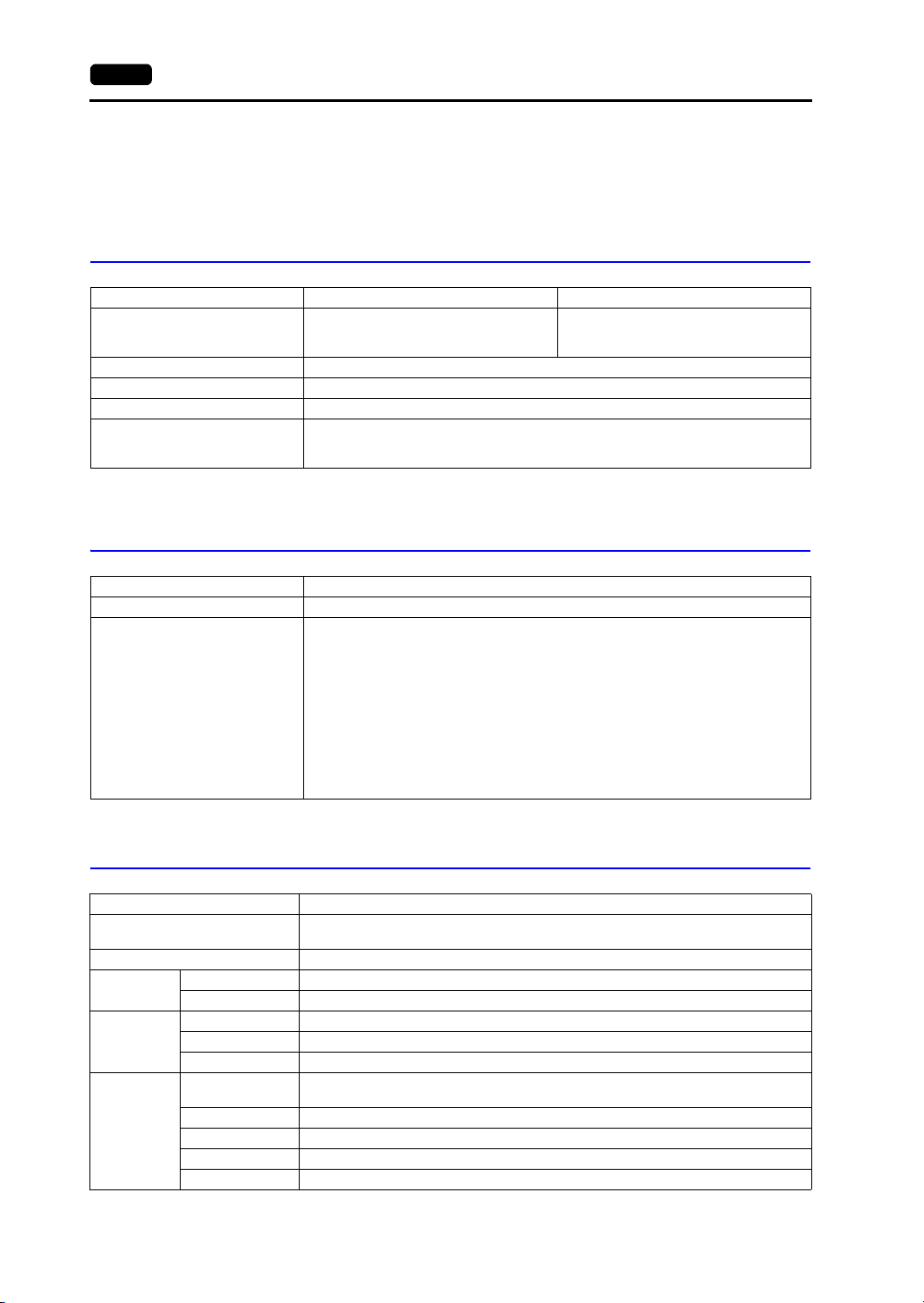
Item Specification
Interface Language
Font Types TrueType fonts, bitmap fonts, Window fonts
Character
Properties
Graphics
Graphic
Properties
*1
Display Properties Normal, blink, bold, shadow, transparent, italic
Colors 65,536 colors (without blinking) / 32,768 colors (with blinking)
Lines Line, continuous line, box, parallelogram, polygon
Circles Circle, arc, sector, ellipse, elliptical arc
Others Pattern, image, data display (graphics library, data sheets)
Line Types
Tile Patterns 16 types (including 8 user-definable patterns)
Display Properties Normal, blinking
Colors 65,536 colors (without blinking) / 32,768 colors (with blinking)
Color Selection Foreground, background, boundary (line)
*1 For more information, refer to the V9 Series Reference Manual 1.
Japanese, English/Western Europe, Chinese (Traditional), Chinese (Simplified), Korean,
6 types (thin, thick, dotted, chain, dashed, two-dot chain)
Line thickness can be selected from 1 to 8 points (excluding thick lines).
Central Europe, Cyrillic, Greek, Turkish, and Baltic
Page 40

Function Performance Specifications
Item Specification
Screens Max. 4,000
Screen Memory 64 MB of flash memory
Switches
Switch Actions
Lamps
Graphs
Numerical Data
Display
Data
Setting
Messages Max. 32,768 lines
Macro Blocks Max. 1,024
Graphics Library Max. 2,560
Overlap Library Max. 4,000
Screen Library Max. 4,000
Data Blocks Max. 1,024
Patterns Max. 1,024
Data Sheets Max. 1,024
Tags Max. 65,536 lines
Page Blocks Max. 2,048
Direct Blocks Max. 1,024
Screen Blocks Max. 1,024
Comments Max. 32,767
Logging Server Fixed cycle, trigger
Alarm Server Real time, alarm, event
Recipes Max. 256
Scheduler Max. 64
MES Setting Max. 256
Device Memory Map Max. 32 8 (PLC1 to PLC8)
Time Display Provided
Hard Copy Provided
Buzzer Provided, 3 sounds (short beep, long beep, continuous beep)
Auto OFF Function Always ON, custom setting
Self-diagnostic Function
Character
Display
Message
Display
*1 The maximum number of parts that can be placed on one screen is 4,096.
For more information on limitations regarding part placement, refer to the V9 Series Operation Manual.
*2 Layer: 11 layers per screen (base + 10 overlap displays including global overlap)
*3 For more information, refer to the separate V9 Series Troubleshooting/Maintenance Manual.
Max. 4,096 per screen
Set, reset, momentary, alternate, illuminated
It is possible to press a function switch and a switch on the display at the same time.
Reverse, blinking, exchange of graphics
Max. 4,096 per screen
Pie, bar, panel meter and closed area graph: Max. 4,096 per screen
Statistics and trend graphs: Max. 256 per layer
Max. 4,096 per screen
Max. 4,096 per screen
Max. 4,096 per screen
Maximum number of characters per line: 100 one-byte characters
Touch switch test function
Confirmation function that uses the status bar
Network diagnostic functions (network test, duplicate IP address test)
*1
(including slider switches and scroll bars)
*1
*1
*1
*3
*3
2. Standard Model 2-15
2
Specifications
*1
*2
*3
Page 41

2-16 2. Standard Model
312.0
245.2
327.8
261.0
47.9
7.0
313.0
246.2
54.9
+0.5
-0
+0.5
-0
Side view
Panel cut-out dimensions
Rear view
Bottom view
(Unit: mm)
Front view
V9120iS External Dimensions and Panel Cut-out Dimensions
Page 42

2. Standard Model 2-17
Side view
Panel cut-out dimensions
Rear view
Bottom view
(Unit: mm)
Front view
V9100iS External Dimensions and Panel Cut-out Dimensions
231.0
215.2
303.8
288.0
2
Specifications
48.0
6.0
54.0
-0
+0.5
216.2
289.0
+0.5
-0
Page 43

2-18 2. Standard Model
Panel cut-out dimensions
Bottom view
(Unit: mm)
Side view Rear view
Front view
V91080iSD External Dimensions and Panel Cut-out Dimensions
235.0
180.0
164.5
219.5
42.9
6.0
48.9
-0
+0.5
165.5
220.5
+0.5
-0
Page 44

3. Lite Model
+0.50+0.50+0.50+0.5
0
3. Lite Model 2-19
General Specifications
Item V9100iC V9100iCD V9080iCD
Standards KC KC, CE (EN61000-6-2, EN61000-6-4), UL508
Permissible Voltage Range
Permissible Momentary
Power Failure
Power Consumption
(Max. Rating)
Power Supply
Rush Current 30 A or less, 3 ms 17 A or less, 6 ms
Withstand Voltage
Insulation Resistance
Operational Ambient
Temperature
Storage Ambient
Temperature
Operational Ambient
Humidity
Storage Ambient Humidity
Altitude 2000 m or less
Atmosphere No corrosive gas, no excessive dust, and no conductive dust
Physical Environment
Overvoltage Category
Contamination Level
Vibration Resistance
Working
Conditions
Mechanical
Shock Resistance
Noise Resistance
Static Electricity Discharge
Working
Electrical
Conditions
Resistance
Weight Approx. 2.0 kg Approx. 1.3 kg
Dimensions W H D 303.8 231.0 54.0 mm 235.0 180.0 48.9 mm
Mounting
Panel Cut-out Dimensions
Conditions
Case Color Light gray
Material PC resin
*2
*3
100 to 240 VAC
15 % to +10 %
(47 to 63 Hz)
Within 20 ms
(100 VAC or higher)
50 VA or less 17 W or less
AC external terminals to FG: 1,500 VAC for 1 minute,
DC external terminals to FG: 500 VAC for 1 minute
AC external terminals to FG: 500 VDC at 10 M or more,
DC external terminals to FG: 500 VDC at 10 M or more
0 C to +50 C
10 C to +60 C
85 % RH or less (without dew condensation)
85 % RH or less (without dew condensation)
Category II
Contamination level 2
Vibration frequency: 5 to 9 Hz Half-amplitude: 3.5 mm, Vibration frequency: 9 to 150 Hz
Constant acceleration: 9.8 m/s
X, Y, and Z: 3 directions, 3 times each (18 times in total)
Noise voltage: 1500 Vp-p, Pulse width: 1 s, Rising time: 1 ns
289.0 216.2 mm 220.5 165.5 mm
JIS B 3502 (IEC61131-2) compliant
2
(1 G), X, Y, and Z: 3 directions (10 times each)
JIS B 3502 (IEC61131-2) compliant
Peak acceleration: 147 m/s
(Measured using a noise simulator)
Compliant with IEC61000-4-2, contact: 6 kV, air: 8 kV
24 VDC 10 %
Within 1 ms
*1
*1
2
(15 G),
*1
*1
2
Specifications
*1 Use the unit in an environment where the wet-bulb temperature is 39C or less, otherwise the unit may be
damaged.
*2 This indicates the distribution section to which the unit is intended to be connected to within the path between
the distribution of the public power network and machinery in the facility.
“Category II” applies to devices supplied with power from mains sockets or similar points. The withstand surge
voltage is 2,500 V for devices rated up to 300 V.
*3 This is an index that expresses the degree of conductive contamination in the environment where the unit is
used.
“Contamination level 2” indicates the condition where only non-conductive contamination occurs. However, due
to condensation, temporary conductive contamination may occur.
Page 45

2-20 3. Lite Model
Installation Specifications
Item Specification
Grounding Less than 100 , FG/SG separated
*1
Protection Structure
Cooling System Natural cooling
Structure Inserted in a mounting panel
Appropriate Mounting Panel Thickness
Panel Front Surface
Rear Case Equivalent to IP20
*1 Protective structure for the front when the V9 series unit is mounted on a mounting panel.
While the protective structure has passed compliance testing, it is not guaranteed under all environments.
*2 Even when the mounting panel thickness is within the specified range, the panel itself may warp depending on
the material and size of the mounting panel.
Use a panel that can withstand the forces of mounting.
Equivalent to IP66, with waterproof gasket
1.5 to 4 mm
*2
Display Specifications
Item V9100iC V9080iC
Display Device TFT color
Display Size 10.4-inch 8.4-inch
Colors
Resolution (W H) 640 480 dots
Dot Pitch (W H) 0.33 0.33 mm 0.267 0.267 mm
Actual Display Dimensions
(W H)
Backlight LED
Backlight Brightness
*2
Halftime
Backlight Auto OFF Function Always ON, custom setting
Brightness Adjustment
Touch Panel Operation
Surface
POWER Lamp
*1 Only for displaying “picture” images and 3D parts. All other content is displayed using 65,536 colors.
*2 Time until the surface brightness becomes 50 % of the initial value at an ambient temperature of 25 C.
16.77 million colors
211.2 158.4 mm 170.88 128.16 mm
Approx. 70,000 hours
System menu: 16 levels
Macro: 128 levels
Surface sheet (PET, 0.188 mm)
On: Normal (green)
Flashing: Backlight, circuit board or power supply failure
*1
Touch Switch Specifications
Item Specification
Type Analog resistance film type
Switch Resolution 1024 1024
Mechanical Life One million activations or more
Surface Treatment Anti-glare treatment, 6 %
Function Switch Specifications
Item Specification
Number of Switches 8
Type Membrane switch
Page 46

Item Specification
Mechanical Life One million activations or more
3. Lite Model 2-21
Interface Specifications
Item Specification
Applicable
Standards
Synchronization Asynchronous type
Data Length 7 or 8 bits
D-sub 9-pin (CN1)
Modular Jack, 8-pin
(MJ1, MJ2)
USB Connector
(U-A / U-B)
Ethernet Port
100BASE-TX /
10BASE-T
(LAN)
SD Card Interface SD/SDHC card support
Communication Interface Unit Connector
(EXT1)
Parity None, even, odd
Stop Bit 1 or 2 bits
Baud Rate
Applications PLC, temperature controller, barcode reader connection, etc.
Applicable
Standards
Applications
Applicable
Standards
Baud Rate High speed 480 Mbps
USB-A
Applications
Applicable
Standards
Baud Rate High speed 480 Mbps
Applications Screen program transfer, PictBridge-compatible printer connection
USB mini-B
Applicable
Standards
Baud Rate 10 Mbps, 100 Mbps
Protocol TCP/IP, UDP/IP
Functions Auto-MDIX, Auto-Negotiation
Recommended
*2
Cable
Applications Screen program transfer, PLC connection, etc.
*1 For details, refer to the V9 Series Connection Manual.
*2 Both straight and cross cables are usable, irrespective of the presence or absence of a hub.
RS-232C, RS-422/485
4800, 9600, 19200, 38400, 57600, 76800 bps, 115 kbps
(For PPI/MPI connection with a Siemens PLC: 187.5 kbps
RS-232C, RS-485 (2-wire connection)
Screen program transfer (MJ1), PLC, temperature controller, barcode reader,
printer, multi-link2, V-Link connection, etc.
Compliant with USB version 2.0
Printer (EPSON ESC/P-R driver), USB flash drive, USB-CFREC-2 (under
development), keyboard, mouse connection, etc.
Compliant with USB version 2.0
IEEE802.3u compliant (100BASE-TX), IEEE802.3 compliant (10BASE-T)
100 UTP (unshielded twist-pair) cable, category 5, max. 100 m long
SX-BUS, OPCN-1, T-Link, Ethernet, CC-Link, PROFIBUS-DP, DeviceNet,
FL-net connection
* The separate communication interface unit “CUR-xx” (under development) is
required.
2
Specifications
*1
)
Page 47

2-22 3. Lite Model
Clock and Backup Memory Specifications
Item Specification
Battery Coin-type lithium primary cell (CR2450S manufactured by Sony Energy Devices)
Backup Memory SRAM, 800 KB
Backup Retention Period Approx. 5 years (ambient temperature at 25 C)
Battery Voltage Drop Detection Provided (allocated the internal device memory address $s167)
Calendar Accuracy
* When using the unit at an ambient temperature other than 25 C, clock deviation may increase. Check and
*
correct the clock periodically.
When powered: Monthly deviation of 210 sec. (ambient temperature at 25 C)
When unpowered: Monthly deviation of 90 sec. (ambient temperature at 25 C, with
battery backup)
Screen Configuration Environment
Item Specification
Configuration Method Dedicated configuration software
Name of exclusive configuration software: V-SFT-6
Computer: Pentium IV 2.0 GHz or above recommended
*1
: Windows XP / XP64 Edition / Vista (32 bit, 64 bit) / 7 (32 bit,
Configuration tool
*1 Administrator privileges are required for installation.
OS
Memory: 1.0 GB or above (2.0 GB or above recommended)
Hard disk capacity: Free space of approx. 2.0 GB or more
Optical disc drive: DVD-ROM drive
Display: Resolution 1024 768 or above
Other: Microsoft. NET Framework 4.0 or 4.5
64 bit) / 8 (32 bit, 64 bit) / 8.1 (32 bit, 64 bit)
Color depth of 16-bit or more
(If a PC does not have .NET Framework 4.0 or 4.5 installed,
Framework 4.0 will be automatically installed on the PC.)
Display Function Specifications
Item Specification
Interface Language
Font Types TrueType fonts, bitmap fonts, Window fonts
Character
Properties
Graphics
Graphic
Properties
*1
Display Properties Normal, blink, bold, shadow, transparent
Colors 65,536 colors (without blinking) / 32,768 colors (with blinking)
Lines Line, continuous line, box, parallelogram, polygon
Circles Circle, arc, sector, ellipse, elliptical arc
Others Pattern, image, data display (graphics library, data sheets)
Line Types
Tile Patterns 16 types (including 8 user-definable patterns)
Display Properties Normal, blink
Colors 65,536 colors (without blinking) / 32,768 colors (with blinking)
Color Selection Foreground, background, boundary (line)
*1 For more information, refer to the V9 Series Reference Manual 1.
Japanese, English/Western Europe, Chinese (Traditional), Chinese (Simplified), Korean,
Central Europe, Cyrillic, Greek, Turkish, and Baltic
6 types (thin, thick, dotted, chain, dashed, two-dot chain)
Line thickness can be selected from 1 to 8 points (excluding thick lines).
Page 48

Function Performance Specifications
Item Specification
Screens Max. 4,000
Screen Memory 64 MB of flash memory
Switches
Switch Actions
Lamps
Graphs
Numerical Data
Display
Data
Setting
Messages Max. 32,768 lines
Macro Blocks Max. 1,024
Graphics Library Max. 2,560
Overlap Library Max. 4,000
Screen Library Max. 4,000
Data Blocks Max. 1,024
Patterns Max. 1,024
Data Sheets Max. 1,024
Tags Max. 65,536 lines
Page Blocks Max. 2,048
Direct Blocks Max. 1,024
Screen Blocks Max. 1,024
Comments Max. 32,767
Logging Server Fixed cycle, trigger
Alarm Server Real time, alarm, event
Recipes Max. 256
Scheduler Max. 64
MES Setting Max. 256
Device Memory Map Max. 32 8 (PLC1 to PLC8)
Time Display Provided
Hard Copy Provided
Buzzer Provided, 3 sounds (short beep, long beep, continuous beep)
Auto OFF Function Always ON, custom setting
Self-diagnostic Function
Character
Display
Message
Display
*1 The maximum number of parts that can be placed on one screen is 4,096.
For more information on limitations regarding part placement, refer to the V9 Series Operation Manual.
*2 Layer: 11 layers per screen (base + 10 overlap displays including global overlap)
*3 For more information, refer to the separate V9 Series Troubleshooting/Maintenance Manual.
Max. 4,096 per screen
Set, reset, momentary, alternate, illuminated
It is possible to press a function switch and a switch on the display at the same time.
Reverse, blinking, exchange of graphics
Max. 4,096 per screen
Pie, bar, panel meter and closed area graph: Max. 4,096 per screen
Statistics and trend graphs: Max. 256 per layer
Max. 4,096 per screen
Max. 4,096 per screen
Max. 4,096 per screen
Maximum number of characters per line: 80 one-byte characters
Touch switch test function
Confirmation function that uses the status bar
Network diagnostic functions (network test, duplicate IP address test)
*1
(including slider switches and scroll bars)
*1
*1
*1
*3
*3
3. Lite Model 2-23
2
Specifications
*1
*2
*3
Page 49

2-24 3. Lite Model
Side view
Panel cut-out dimensions
Rear view
Bottom view
(Unit: mm)
Front view
V9100iC External Dimensions and Panel Cut-out Dimensions
303.8
231.0
215.2
54.0
288.0
48.0
6.0
-0
+0.5
216.2
289.0
+0.5
-0
Page 50

3. Lite Model 2-25
Panel cut-out dimensions
Bottom view
(Unit: mm)
Side view Rear view
Front view
V9080iCD External Dimensions and Panel Cut-out Dimensions
180.0
164.5
235.0
219.5
2
42.9
6.0
Specifications
48.9
-0
+0.5
165.5
220.5
+0.5
-0
Page 51

2-26 3. Lite Model
Please use this page freely.
Page 52

3
Names and
Specifications of
1. Names and Functions of Components
2. Specifications of Components
Components
Page 53

1. Names and Functions of Components 3-1
V910xiW
1. Names and Functions of Components
Advanced Model
1
3
-
+
2
15 16 17 18 19 20
14
21
4
5
6
10
7
11
12
8
13
9
1. Display
This is the display area.
2. POWER lamp
This lamp illuminates green when the V9 series is powered ON and operating normally.
The lamp flashes when there is a failure (circuit board failure, power supply failure).
3. Communication interface unit connector (EXT1)
This connector is used to connect an optional “CUR-xx” unit (under development *) for SX-BUS,
OPCN-1, T-Link, CC-Link *, Ethernet, PROFIBUS-DP *, DeviceNet *, or FL-net communication.
4. Fall prevention tabs
These tabs prevent the V9 series unit from falling off the mounting panel until the mounting fixtures
are tightened.
5. Connector for optional unit (EXT2)
This connector is used to connect each optional “GUR-xx” unit for video input, RGB input, and
RGB output.
6. SD card access LED
This LED flashes when the unit is reading from or writing to an SD card.
7. Battery holder
This part contains the backup battery for the SRAM and clock.
When the battery voltage drops, replace the battery with a new one.
8. DIP switches
This 8-bit DIP switch is used for setting the terminating resistance of the CN1 signal line and the
MJ1/MJ2 RS-485 signal line.
9. USB cable clamp hole
This clamp hole is used to attach a USB cable tie.
10. SD card slot (SD)
This slot is where an SD card can be inserted.
11. Audio output connector (AUDIO)
This terminal is used for audio output.
3
Names and Specifications of Components
Page 54

3-2 1. Names and Functions of Components
12. Connector for wireless LAN dipole antenna (WLAN)
Only for wireless LAN I/F models.
This connector is for connecting the external dipole antenna “V9-ANT” (optional) for wireless LAN.
13. 100BASE-TX/10BASE-T connector (LAN2)
This connector is used for Ethernet communication.
14. Power supply terminal block
This terminal block is for supplying power (24 VDC) to the V9 series unit.
15. Modular jack 1 (MJ1)
This connector is used for screen program transfer and connection with PLCs or other peripheral
devices.
16. Modular jack 2 (MJ2)
This connector is used for connection with PLCs or other peripheral devices.
17. PLC communication connector (CN1)
This connector is used for connection to a controller (PLC, temperature controller, inverter, etc.).
18. 100BASE-TX/10BASE-T connector (LAN)
This connector is used for Ethernet communication.
19. USB-A (U-A)
This port is used to connect a printer, USB flash drive, “USB-CFREC -2” USB CF card recorder
(optional unit, under development), keyboard, or mouse.
20. USB mini-B (U-B)
This port is used for transferring screen programs or connecting a PictBridge-compatible printer.
21. Mounting holes
The mounting holes are used for inserting fixtures when securing the V9 series unit to a mounting
panel.
Page 55

1. Names and Functions of Components 3-3
1
2
11
19
10
15 16 17 18
12
13
14
3
4
5
6
7
9
8
V9071iW
V9071iW+DUR-00
20 21
3
Names and Specifications of Components
1. Display
This is the display area.
2. POWER lamp
This lamp illuminates green when the V9 series is powered ON and operating normally.
The lamp flashes when there is a failure (circuit board failure, power supply failure).
3. SD card access LED
This LED flashes when the unit is reading from or writing to an SD card.
4. SD card slot (SD)
This slot is where an SD card can be inserted.
5. Battery holder
This part contains the backup battery for the SRAM and clock.
When the battery voltage drops, replace the battery with a new one.
6. Communication interface unit connector (EXT1)
This connector is used to connect the optional “DUR-00” unit, or an optional “CUR-xx” unit (under
development *) for SX-BUS, OPCN-1, T-Link, CC-Link *, Ethernet, PROFIBUS-DP *, DeviceNet *,
or FL-net communication.
7. USB cable clamp hole
This clamp hole is used to attach a USB cable tie.
8. USB mini-B (U-B)
This port is used for transferring screen programs or connecting a PictBridge-compatible printer.
Page 56

3-4 1. Names and Functions of Components
9. Fall prevention tabs
These tabs prevent the V9 series unit from falling off the mounting panel until the mounting fixtures
are tightened.
10. DIP switches
This 8-bit DIP switch is used for setting the terminating resistance of the MJ1/MJ2 RS-485 signal
line.
11. Sliding switch
This switch is for selecting the RS-232C/RS-485 signal (2-wire connection) or the RS-422 signal
(4-wire connection) for MJ2. The upper side is for the RS-232C/RS-485 signal (2-wire connection)
and the lower side is for the RS-422 signal (4-wire connection).
12. Power supply terminal block
This terminal block is for supplying power (24 VDC) to the V9 series unit.
13. 100BASE-TX/10BASE-T connector (LAN2)
This connector is used for Ethernet communication.
14. Connector for wireless LAN dipole antenna (WLAN)
Only for wireless LAN I/F models.
This connector is for connecting the external dipole antenna “V9-ANT” (optional) for wireless LAN.
15. USB-A (U-A)
This port is used to connect a printer, USB flash drive, “USB-CFREC -2” USB CF card recorder
(optional unit, under development), keyboard, or mouse.
16. Modular jack 1 (MJ1)
This connector is used for screen program transfer and connection with PLCs or other peripheral
devices.
17. Modular jack 2 (MJ2)
This connector is used for connection with PLCs or other peripheral devices.
18. 100BASE-TX/10BASE-T connector (LAN)
This connector is used for Ethernet communication.
19. Mounting holes
The mounting holes are used for inserting fixtures when securing the V9 series unit to a mounting
panel.
20. DIP switches (optional “DUR-00” unit)
These switches are used for setting the terminating resistance of the CN1 signal line.
21. PLC communication connector (CN1) (optional “DUR-00” unit)
This connector is used for connection to a controller (PLC, temperature controller, inverter, etc.).
Page 57

Standard Model
1
3
2
4
9
15
22
10
8
7
16 17 18 19 20 21
6
11
12
13
14
5
1
3
2
4
9
15
22
10
8
7
16 17 18 19 20 21
6
11
12
13
14
5
V9120iS
V9100iS
V9080iSD
1. Names and Functions of Components 3-5
1
4
2
3
15
16 17 18 19 20 21
22
5
6
7
11
8
12
13
9
14
10
3
Names and Specifications of Components
Page 58

3-6 1. Names and Functions of Components
1. Display
This is the display area.
2. Function switches
There are 8 function switches comprising the [SYSTEM] switch and [F1] to [F7] switches.
The [SYSTEM] switch is used to display or hide the system menu (for switching between the RUN
and Local modes, adjusting brightness, etc.).
Switches [F1] to [F7] can be used as user switches in RUN mode.
3. POWER lamp
This lamp illuminates green when the V9 series is powered ON and operating normally. The lamp
flashes when there is a failure (backlight failure, circuit board failure, power supply failure).
4. Communication interface unit connector (EXT1)
This connector is used to connect each optional “CUR-xx” unit (under development *) for SX-BUS,
OPCN-1, T-Link, CC-Link *, Ethernet, PROFIBUS-DP *, DeviceNet *, and FL-net communication.
5. Fall prevention tabs
These tabs prevent the V9 series unit from falling off the mounting panel until the mounting fixtures
are tightened.
6. Connector for optional unit (EXT2)
This connector is used to connect each optional “GUR-xx” unit for video input, RGB input, and
RGB output.
7. SD card access LED
This LED flashes when the unit is reading from or writing to an SD card.
8. Battery holder
This part contains the backup battery for the SRAM and clock.
When the battery voltage drops, replace the battery with a new one.
9. DIP switches
This 8-bit DIP switch is used for setting the terminating resistance of the CN1 signal line and the
MJ1/MJ2 RS-485 signal line.
10. USB cable clamp hole
This clamp hole is used to attach a USB cable tie.
11. SD card slot (SD)
This slot is where an SD card can be inserted.
12. Audio output connector (AUDIO)
This terminal is used for audio output.
13. Connector for wireless LAN dipole antenna (WLAN)
Only for wireless LAN I/F models.
This connector is for connecting the external dipole antenna “V9-ANT” (optional) for wireless LAN.
14. 100BASE-TX/10BASE-T connector (LAN2)
Only for additional wired LAN I/F models.
This connector is used for Ethernet communication.
15. Power supply terminal block
This terminal block supplies power to the V9 series unit (100 to 240 VAC, 24 VDC).
16. Modular jack 1 (MJ1)
This connector is used for screen program transfer and connection with PLCs or other peripheral
devices.
17. Modular jack 2 (MJ2)
This connector is used for connection with PLCs or other peripheral devices.
18. PLC communication connector (CN1)
This connector is used for connection to a controller (PLC, temperature controller, inverter, etc.).
19. 100BASE-TX/10BASE-T connector (LAN)
This connector is used for Ethernet connection.
Page 59

1. Names and Functions of Components 3-7
20. USB-A (U-A)
This port is used to connect a printer, USB flash drive, “USB-CFREC-2” USB CF card recorder
(optional unit, under development), keyboard, or mouse.
21. USB mini-B (U-B)
This port is used for transferring screen programs or connecting a PictBridge-compatible printer.
22. Mounting holes
The mounting holes are used for inserting fixtures when securing the V9 series unit to a mounting
panel.
3
Names and Specifications of Components
Page 60

3-8 1. Names and Functions of Components
1
3
2
8
11
18
9
7
6
12 13 14 15 16 17
10
4
5
1
3
2
8
11
18
9
7
6
12 13 14 15 16 17
10
4
5
V9100iC
V9080iCD
Lite Model
1. Display
This is the display area.
2. Function switches
There are 8 function switches comprising the [SYSTEM] switch and [F1] to [F7] switches.
The [SYSTEM] switch is used to display or hide the system menu (for switching between the RUN
and Local modes, adjusting brightness, etc.).
Switches [F1] to [F7] can be used as user switches in RUN mode.
3. POWER lamp
This lamp illuminates green when the V9 series is powered ON and operating normally. The lamp
flashes when there is a failure (backlight failure, circuit board failure, power supply failure).
4. Communication interface unit connector (EXT1)
This connector is used to connect each optional “CUR-xx” unit (under development *) for SX-BUS,
OPCN-1, T-Link, CC-Link *, Ethernet, PROFIBUS-DP *, DeviceNet *, and FL-net communication.
5. Fall prevention tabs
These tabs prevent the V9 series unit from falling off the mounting panel until the mounting fixtures
are tightened.
Page 61

1. Names and Functions of Components 3-9
6. SD card access LED
This LED flashes when the unit is reading from or writing to an SD card.
7. Battery holder
This part contains the backup battery for the SRAM and clock.
When the battery voltage drops, replace the battery with a new one.
8. DIP switches
This 8-bit DIP switch is used for setting the terminating resistance of the CN1 signal line and the
MJ1/MJ2 RS-485 signal line.
9. USB cable clamp hole
This clamp hole is used to attach a USB cable tie.
10. SD card slot (SD)
This slot is where an SD card can be inserted.
11. Power supply terminal block
This terminal block supplies power to the V9 series unit (100 to 240 VAC, 24 VDC).
12. Modular jack 1 (MJ1)
This connector is used for screen program transfer and connection with PLCs or other peripheral
devices.
13. Modular jack 2 (MJ2)
This connector is used for connection with PLCs or other peripheral devices.
14. PLC communication connector (CN1)
This connector is used for connection to a controller (PLC, temperature controller, inverter, etc.).
15. 100BASE-TX/10BASE-T connector (LAN)
This connector is used for Ethernet connection.
16. USB-A (U-A)
This port is used to connect a printer, USB flash drive, “USB-CFREC-2” USB CF card recorder
(optional unit, under development), keyboard, or mouse.
17. USB mini-B (U-B)
This port is used for transferring screen programs or connecting a PictBridge-compatible printer.
18. Mounting holes
The mounting holes are used for inserting fixtures when securing the V9 series unit to a mounting
panel.
3
Names and Specifications of Components
Page 62

3-10 2. Specifications of Components
Bottom view Bottom view
V9100 V9080
Rear view
V9071iW
9
5
6
1
2. Specifications of Components
Serial Connector (CN1)
This connector is used to connect a controller or barcode reader via RS-232C, or connect a controller
via RS-422/485.
For the V9071iW, attach the optional “DUR-00” unit to add this serial connector.
The serial connector pins correspond to the signals as shown below.
CN1 (D-sub 9-pin, female)
Pin No.
1 NC Not used + RD Receive data (+)
2 RD Receive data RD Receive data ()
3 SD Send data SD Send data ()
4 NC Not used + SD Send data (+)
5 SG Signal ground SG Signal ground
6 NC Not used + RTS Request to send (+)
7 RTS Request to send RTS Request to send ()
8 CTS Clear to send NC Not used
9 NC Not used + 5 V
*1 The signal level can be changed between RS-232C and RS-422/485 in the configuration software.
When RS-232C is selected, set DIP switches 5 and 7 to the OFF position.
(For details on DIP switches, refer to “DIP Switches (DIPSW)” (page 3-28).)
*2 When RS-422/485 is selected, +5 V is output from pin No. 9.
This +5 V is used as the power supply for the external terminating resistance when performing RS-422/485
communication. It cannot be used as an external power supply.
Signal Description Signal Description
RS-232C
*1
RS-422 / RS-485
Use prohibited
*1
*2
Page 63

Recommended Connector
Bottom view Bottom view
V9100 V907iW
8 76 5 43 21
The following connector is recommended for custom-made cables.
Recommended
Connector
17JE-23090-02(D8C)-CG
manufactured by DDK
Applications
Application V-SFT-6 Setting Refer to
PLC/temperature controller connection Required
Multi-link/Multi-link2 communication Required
Modular Jack (MJ1/MJ2)
The modular jacks are used for connection to a screen program transfer cable (MJ1 only), temperature
controller, barcode reader, and other devices.
2. Specifications of Components 3-11
D-sub 9-pin / male / inch screw thread (#4-40UNC) type
/ with hood / lead and cadmium free
V9 Series Connection ManualBarcode reader connection Required
3
Names and Specifications of Components
The pins of MJ1 and MJ2 correspond to the signals as shown below.
V9120, V9100, V9080 series
MJ1/2 Pin No. Signal Description
1 +SD/RD RS-485 + data
2 SD/RD RS-485 data
3+5 V
4+5 V
5SG
6SG
7 RD RS-232C receive data
8 SD RS-232C send data
*1 Allowable current for the +5 V external power supply at MJ1/MJ2 of the V9 series unit
For MJ1, MJ2, and USB-A, the maximum allowable current is 150 mA in total (only when the mounting angle is
60 to 120).
Externally supplied +5 V
Signal ground
*1
Page 64

3-12 2. Specifications of Components
8 76 5 43 21
Rear view
Sliding switch (Upon delivery: Up)
Up: RS-232C, RS-485 (2-wire connection)
Down: RS-422 (4-wire connection)
V9071iW series
MJ1 MJ2
Pin No.
1 +SD/RD RS-485 + data
2 -SD/RD RS-485 - data
3+5V
4+5V +5V
5SG
6SG SG
7 RD RS-232C receive data
8 SD RS-232C send data
*1 The MJ2 sliding switch is on the rear side of the V9071iW.
*2 Allowable current for the +5 V external power supply at MJ1/MJ2 of the V9 series unit
Signal Description
Externally supplied +5 V
Signal ground
For MJ1, MJ2, and USB-A, the maximum allowable current is 150 mA in total (only when the mounting
angle is 60 to 120).
MJ1/2
Sliding
Switch
Up +SD/RD RS-485 + data
Down +SD RS-422 + send data
Up -SD/RD RS-485 - data
Down -SD RS-422 - send data
*2
-
Up RD RS-232C receive data
Down +RD RS-422 + receive data
Up SD RS-232C send data
Down -RD RS-422 - receive data
Signal Description
*1
+5V
SG
Externally supplied +5 V
Signal ground
*2
Applications
Application V-SFT-6 Setting Refer to
PLC/temperature controller connection Required
V9 Series Connection ManualBarcode reader connection Required
Multi-link/Multi-link2 communication Required
Ladder transfer function
Screen program transfer Not required V9 Series Operation Manual
Printer connection Required V9 Series Reference Manual 1
*1 The ladder transfer function cannot be used simultaneously with 1:n communication (multi-drop) or multi-link
communication.
*1
Required V9 Series Reference Manual 2
Page 65

USB-A (Master Port)
Bottom view Bottom view
V9100 V9071iW
Enlarged view
USB-A
V9
USB flash drive
This connector is used to connect a printer, USB flash drive, barcode reader, keyboard, mouse, or
USB hub. The USB-A port of the V9 unit complies with USB version 2.0.
Applications
Application V-SFT-6 Setting Refer to
Printer connection Required V9 Series Reference Manual 1
USB flash drive connection Required See page 3-13.
Barcode reader connection Required V9 Series Connection Manual 3
Keyboard/numeric keypad connection Required See page 3-14.
Mouse connection Not required See page 3-15.
USB hub connection Not required See page 3-16.
2. Specifications of Components 3-13
3
Names and Specifications of Components
USB Flash Drives
A USB flash drive can be connected to the V9 series unit to perform operations including screen
program transfers or saving of log data.
Connection Example
USB Flash Drive Specifications
The type of USB flash drives that can be used with the V9 series are shown below.
V-SFT-6 Setting
Required settings vary according to the application.
For more information, refer to V9 Series Reference Manual 2.
Storage Capacity File System
USB flash drive
2 GB max. FAT
32 GB ma x. FAT, FAT32
Page 66

3-14 2. Specifications of Components
Keyboard
or
Numeric keypad
Notes on Handling a USB Flash Drive
1. When removing the USB flash drive, select [Storage Removal] in the system menu, or press the
[Storage Removal] switch.
2. Do not turn off power to the unit when the USB flash drive is being accessed.
3. Make a backup copy of the USB flash drive at regular intervals.
4. If a disk error occurs and data read/write operations are disabled, execute ScanDisk on Windows
and try to restore the disk.
If the disk cannot be restored, format the device. Note that formatting will completely erase all
stored data. (For information on executing ScanDisk on Windows, refer to the relevant Windows
manual.)
5. USB flash drives have a limited number of write cycles. Consequently, frequent writing at short
intervals may shorten the service life of USB flash drives. When using a USB flash drive to save
logging/alarm data, take the logging time/monitoring intervals into consideration. Also, avoid
repeated writing using the CYCLE macro command.
Keyboard and Numeric Keypad
Numeric values and characters can be entered by connecting a keyboard or numeric keypad to the V9
series unit.
Connection Example
V9
USB-A
Compatible Keyboards
Type Description
Japanese keyboard 106 keyboard, 109 keyboard, etc.
US standard keyboard 101 keyboard, 104 keyboard, etc.
Numeric keypad
V-SFT-6 Setting
An [Entry] icon must be registered on the screen where the keyboard is to be used.
In addition, setting of the numerical data or character display parts of [Entry Target] selected under
[Function] is required.
For details, refer to the V9 Series Reference Manual.
Page 67

Mouse
USB-A
V9
Mouse
2. Specifications of Components 3-15
V9 Series Unit Setting
In the Local mode, select the type of keyboard to be connected.
For details, refer to the separate V9 Series Troubleshooting/Maintenance Manual.
A mouse can be used to operate screens displayed on the V9 series unit by connecting a mouse to the
unit.
The mouse pointer displayed on the unit is shown below.
3
Names and Specifications of Components
Connection Example
Mouse Operation
The mouse operations available on the unit are shown below.
Mouse Operation Action
Movement Moving the mouse pointer
Left-click Pressing a switch
Page 68

3-16 2. Specifications of Components
USB-A
USB-B
USB-B
V9
Printer
*
USB hub
*
*
USB Hub
Devices like printers can be used at the same time by connecting a USB hub to the V9 series unit.
Connection Example
* A parallel printer can also be connected. (In this case, a parallel printer that is compatible with the V9 series
and a commercially available parallel-to-USB cable must be used (recommended cable: UC-PGT
manufactured by ELECOM).) For more information on compatible printer models, visit our website
(http://www.monitouch.com/)).
Combinations of Connected Devices
Combination of devices usable at the same time:
Combination of devices not usable at the same time:
Printer
Printer
USB Flash Drive
USB Barcode
Reader
Keyboard/
Numeric Keypad
USB Mouse
* If these devices are connected at the same time, only the USB barcode reader will be recognized.
-
USB Flash
Drive
-
USB Barcode
Reader
-
Keyboard/
Numeric Keypad
USB Mouse
Page 69

Notes
Bottom view
V9100
Rear view
V9071iW
Enlarged view
A maximum of two USB hubs can be connected (cascaded) to the V9 series unit.
Note that performance will decrease when two USB hubs are connected.
Do not turn off the power adaptor or disconnect the connector between the power adaptor and
the USB hub when the USB hub is connected to the V9 series unit and powered by the
adaptor.
Doing so may prevent sufficient power supply to the V9 series unit resulting in faulty operation
such as repeated restarting.
When connecting two USB hubs to the V9 series unit, supply power to each USB hub using
the adaptor provided with each hub.
Even when connecting only one USB hub, use the provided power supply adaptor (if
provided).
USB mini-B (Slave Port)
This connector is used for screen program transfer or connection with a PictBridge-compatible printer.
The USB mini-B port of the V9 unit complies with USB version 2.0.
2. Specifications of Components 3-17
3
Names and Specifications of Components
Applications
Application V-SFT-6 Setting Refer to
Ladder transfer function
PictBridge-compatible printer
connection
Screen program transfer Required V9 Series Setup Manual
*1 The ladder transfer function cannot be used simultaneously with 1:n communication (multi-drop) or multi-link
communication.
*1
Required V9 Series Reference Manual 2
Required V9 Series Reference Manual 1
Page 70

3-18 2. Specifications of Components
Bottom view Bottom view
V9100 V907iW
CAUTION
8 76 5 43 21
CAUTION
LAN Connector (LAN)
This connector is used for Ethernet communication with controllers and supports 100BASE-TX and
10BASE-T.
The MJ1 (or MJ2) and LAN connectors are both 8-pin modular jacks.
Check the connector names on the unit and insert cables into the correct connectors.
Do not connect any peripheral device that will carry excess voltage to the LAN
connector.
The LAN connector pins correspond to the signals as shown below.
Specification: IEEE802.3 (u)-compliant, UDP/IP and TCP/IP support, Auto-MDIX and
Auto-Negotiation function support
LAN Pin No. Signal Description
1 TX+ Ethernet send signal (+)
2TX Ethernet send signal ()
3 RX+ Ethernet receive signal (+)
4 NC Not used
5 NC Not used
6RX Ethernet receive signal ()
7 NC Not used
8 NC Not used
Applications
Application V-SFT-6 Setting Refer to
PLC/temperature controller connection Required
Multi-link2 (Ethernet)/
1:n Multi-link2 (Ethernet)
communication
Ladder transfer function
Screen program transfer Required V9 Series Setup Manual
Ethernet communication function Required V9 Series Reference Manual 2
*1 The ladder transfer function cannot be used simultaneously with 1:n communication (multi-drop) or multi-link
communication.
*1
Required
Required V9 Series Reference Manual 2
Wiring
When using the LAN port, keep the LAN cable away from the power supply cable as
much as possible.
Use a commercially available cable. Using a custom-made cable may prevent normal connection to
the network.
Recommended cable: 100 UTP (unshielded twist-pair) cable, category 5, max. 100 m long
* Both straight and cross cables are usable, irrespective of the presence or absence of a hub.
V9 Series Connection Manual
Page 71

Additional LAN Connector (LAN2)
Side view
V901xiW
Side view
V9071iW
CAUTION
(Only for Additional Wired LAN I/F Models)
This connector is used for Ethernet communication with controllers and supports 100BASE-TX and
10BASE-T.
The MJ1 (or MJ2) and LAN connectors are both 8-pin modular jacks.
Check the connector names on the unit and insert cables into the correct connectors.
Do not connect any peripheral device that will carry excess voltage to the LAN
connector.
2. Specifications of Components 3-19
3
Names and Specifications of Components
The specifications and applications are the same as “ LAN Connector (LAN)” (page 3-18).
Page 72

3-20 2. Specifications of Components
Side view
V901xiW
Side view
V9071iW
Connector for Wireless LAN Dipole Antenna (WLAN) (Only for Wireless LAN I/F Models)
This connector is for connecting the external dipole antenna “V9-ANT” (optional) for wireless LAN.
Wireless LAN specifications are shown below.
Item Specification
Wireless LAN
Standards
Communication
Frequency
Channels
Transmission
Mode
Transmission
Rate
Antenna Power
(Output Power)
Complying
Antennas
Polarization Vertical polarization
Horizontal
radiation pattern
Operation Mode
Authentication OPEN SYSTEM, WPA-PSK, WPA2-PSK
Encryption
Method
Clients
(per IS-AP)
Conformance
Standards
*1 According to wireless LAN standards, the 2.4 GHz communication frequency band can be used indoors and
outdoors. However, if UL standard certification is required, installation conditions must conform to those
designated by the UL standard.
*2 Channels 1 to 11 which can be used in all countries are enabled. Channels 12 to 14 cannot be used.
*3 The V9 series unit will not conform to the above laws if using any antenna other than the built-in antenna or the
optional V9-ANT for wireless LAN connection.
*4 V9120iSRD, V9100iSRD and V9080iSRD conform with only the Japanese Radio Law.
IEEE802.11b, IEEE802.11g, IEEE802.11n
2.4 GHz band (2.412 GHz to 2.472 GHz)
*1
*2
1 to 11 ch (for all countries) (Channel spacing: 5 MHz)
11b: Direct-sequence spread spectrum (DS-SS)
11g: Orthogonal frequency-division multiplexing (OFDM)
11n: Orthogonal frequency-division multiplexing (OFDM)
11b: 1, 2, 5.5, 11 Mbps
11g: 6, 9, 12, 18, 24, 36, 48, 54 Mbps
11n, HT20 (GI: 800 ns) 1 stream: 6.5, 13, 19.5, 26, 39, 52, 58.5, 65 Mbps
11n, HT20 (GI: 400 ns) 1 stream: 7.2, 14.4, 21.7, 29.9, 43.3, 57.8, 65, 72.2 Mbps
Max. 10 mW/MHz
Built-in antenna of the V9 series unit
V9-ANT (optional): External dipole antenna for wireless LAN
Built-in antenna of V9 series unit: Directional
V9-ANT (optional): Omnidirectional
Infrastructure mode (access point, station)
Ad-hoc mode
* Selected in Local mode.
None, WEP, TKIP, AES
Max. 6
Japanese Radio Law: Technical Regulations Conformity Certification, Article 2, clause
1-19
FCC Part15 SubPart C
*3 *4
IC RSS210,Gen
R&TTE: EN300328, EN301489-1, EN301489-17, EN62311, EN60950-1
KC
Page 73

Notes on Wireless LAN
An antenna is built into the V9 series unit for use as a wireless communication antenna. Consider
your usage environment, and if necessary, use Hakko Electronics’ “V9-ANT” external dipole
antenna (optional).
(The built-in antenna of the V9 series unit can be used for wireless LAN communication within 10
meters from the front side of the V9 series unit. For wireless LAN communication around the V9
series unit (360) or more than 10 meters away from the V9 series unit, use of the “V9-ANT” is
recommended.)
Radio waves used by wireless LAN pass through wood and glass, and therefore communication is
possible even if floors and walls are made of wooden or glass material. However, radio waves
cannot penetrate reinforcing rods, metal, or concrete, so if these materials are used
communication is not possible.
Signal intensity can be checked using the Received Signal Strength Indication (RSSI) as a
guideline. Placing the V9 series unit (access point) so that the RSSI value is higher will attain a
more stable communication status.
A low RSSI value, which does not improve by moving the position of the V9 series unit (access
point) or antenna, indicates that the radio wave intensity is weakened due to a long communication
distance or physical obstructions.
The radio waves used for wireless LAN communication are divided into frequency bands called
channels (ch). The V9 series spaces the 2.4 GHz band into 11 channels (1 to 11 ch) at 5 MHz
intervals. However, if the same channel is used or neighboring channels interfere with each other,
communication speed may be reduced.
We recommend selecting channels for access points so that the frequencies do not overlap, such
as 1 ch, 5 ch and 9 ch (when using MONITOUCH as an access point).
2. Specifications of Components 3-21
3
Names and Specifications of Components
Notes on Radio Waves
The wireless LAN function of the V9 series corresponds to “radio equipment for radio stations
(antenna power: 10 mW/MHz or less) of low-power data communication systems” defined by radio
law, and therefore does not require a radio license.
Depending on the peripheral environment or installation conditions, data transmission via wireless
LAN may be unstable compared to wired connections and result in packet loss.
Be sure to check the connection before actual use.
Do not use the wireless LAN function in the following situations.
1) Near a person who uses a cardiac pacemaker: The function may cause electromagnetic
interference in cardiac pacemakers, leading to malfunctions.
2) Near medical devices: The function may cause electromagnetic interference in medical
devices, leading to malfunctions.
3) Near microwaves: Microwaves may cause electromagnetic interference in wireless
communications of the V9 series unit.
Page 74

3-22 2. Specifications of Components
Radio equipment which use the 2.4 GHz frequency band
Models that support wireless LAN use the 2.4 GHz frequency band. This frequency band is used
for industrial, scientific, and medical equipment; on-site radio stations (requiring a radio license)
and certain low-power radio stations (no radio license required) for identifying moving objects in
production lines; and amateur radio stations (requiring a radio license).
1) Before using the wireless LAN function, check that there are no on-site radio stations and
certain low-power radio stations for identifying moving objects or amateur radio stations in use
nearby.
2) If ever the V9 series unit causes wave interference to an on-site radio station for identifying
moving objects, immediately stop wireless LAN communication and ensure that waves are no
longer emitted. Then take necessary actions to resolve the interference (e.g. changing
frequencies, relocating, installing partitions).
3) If the V9 series unit causes wave interference to a certain low-power radio station for
identifying moving objects, or if any other problem occurs, contact your distributor.
The product will not conform to radio laws if using any antenna other than the built-in antenna of
the V9 series unit or the external dipole antenna “V9-ANT” (optional).
The wireless LAN function conforms to the radio standards in the following countries *.
Never use the V9 series unit outside of these countries.
Australia, Belgium, Canada, Czech, Denmark, Finland, France, Germany, Great Britain, Greek,
Hungary, Ireland, Italia, Japan, Netherlands, Norway, Poland, Portugal, Slovakia, Slovenia, South
Korea, Spain, Sweden, Switzerland, United States of America
* V9120iSRD, V9100iSRD, and V9080iSRD are available for use in Japan only.
Notes on Security
A wireless LAN transmits data between a computer and a wireless LAN access point without using a
LAN cable. Therefore, as long as radio waves are transmitted, LAN connection can be established
whenever desired.
On the other hand, within a certain range, radio waves will pass through all obstructions (such as
walls) and reaches the entire area. If security settings are not made, the following problems may occur.
Transmission contents can be eavesdropped on
A malicious third party can eavesdrop on communication contents and steal identity such as your
Unauthorized intrusions
A malicious third party may access personal or corporate networks without authorization and steal
An attacker can impersonate you and send out false information (impersonation).
Communication contents can be intercepted and then manipulated before sending (manipulation).
Data and systems can be destroyed using a computer virus (destruction).
Principally, models that support wireless LAN have security functions. If such functions are properly
configured before use, any risks of sustaining the above attacks can be reduced.
We recommend configuring security functions before use at your own judgment and responsibility, and
fully understand the problems that may occur if the V9 series unit is used without configuring security
functions.
Applications
Screen program transfer Not required V9 Series Operation Manual
Ethernet communication function
(excluding PLC 8WAY communication)
* Configurations in Local mode of the V9 series unit are required to use wireless LAN.
ID, password, and credit card numbers, or eavesdrop on email contents.
identity or confidential information (information leakage).
Application V-SFT-6 Setting Refer to
Depends on
function
V9 Series Reference Manual 2
For details, refer to the V9 Series Troubleshooting/Maintenance Manual.
Page 75

2. Specifications of Components 3-23
Rear view Rear view
V9100 V9071iW
Communication Interface Unit Connector (EXT1)
This is a connector for attaching the communication interface unit “CUR-xx”.
The connector on the V9071iW can also be used for attaching the optional “DUR-00” unit.
The types of communication interface units are shown below.
Type Communication Specification
CUR-00 OPCN-1
CUR-01 T-Link
CUR-02 (under development) CC-Link
CUR-03 Ethernet
CUR-04 (under development) PROFIBUS-DP
CUR-06 SX BUS
CUR-07 (under development) DeviceNet
CUR-08 FL-net
* For details on specifications and how to attach a communication interface unit, refer to the
respective V9 Series Communication Unit Specifications.
3
Names and Specifications of Components
Page 76

3-24 2. Specifications of Components
Rear view Rear view
V9100iS V9080iS
Optional Unit Connector (EXT2) (V910xiW/Standard Models Only)
This is a connector for attaching the optional “GUR-xx” unit.
The types of optional units are shown below.
Type Communication Specification
GUR-01 RGB input 1 CH
GUR-02 RGB output 1 CH
CUR-04 Video input 1 CH
* For details on specifications and how to attach an optional unit, refer to the respective instruction
manual.
Page 77

SD Card Interface (SD)
Side view
Side view
V9100
V907iW
This is the interface used for inserting an SD card.
An SD card can be used to transfer screen programs and save log data and image data.
SD Card Specifications
SD cards that are compatible with the V9 series are shown below.
* This manual collectively refers to the following cards as “SD cards”.
SDHC card 4 GB to 32 GB FAT32
2. Specifications of Components 3-25
3
Names and Specifications of Components
Card Type Capacity File System
SD card 2 GB max. FAT
SD Card Access LED
The state of the SD card access LED is configured as shown below.
Applications
For details on functions that use an SD card, refer to the separate V9 Series Reference Manual 2.
For details on reading and writing between an SD card and the V9 series unit, refer to the separate
V9 Series Troubleshooting/Maintenance Manual.
LED Description
Off
Flashing red
The SD card is not being accessed.
The SD card can be removed.
The SD card is being accessed.
The LED turns off when access is complete.
Page 78

3-26 2. Specifications of Components
Notes on SD Card Handling
1. The SD card access LED flashes red when the SD card is being accessed. Do not remove the SD
card while the LED is flashing. Doing so may destroy data on the SD card.
2. When removing the SD card, check that the SD card access LED has turned off, then select
[Storage Removal] in the system menu, or press the [Storage Removal] switch.
3. Do not turn off power to the unit when the SD card is being accessed.
4. Make a backup copy of the SD card at regular intervals.
5. If a disk error occurs and data read/write operations are disabled, execute ScanDisk on Windows
and try to restore the disk.
If the disk cannot be restored, format the device. Note that formatting will completely erase all
stored data. (For information on executing ScanDisk on Windows, refer to the relevant Windows
manual.)
6. SD cards have a limited number of write cycles. Consequently, frequent writing at short intervals
may shorten the service life of SD cards. When using an SD card to save logging/alarm data, take
the logging time/monitoring intervals into consideration. Also, avoid repeated writing using the
CYCLE macro command.
Page 79

2. Specifications of Components 3-27
Side view Side view
V9100iS V9080iS
Audio Output Connector (AUDIO) (V910xiW/Standard Models Only)
This terminal is used for audio output.
* An external speaker with a built-in amplifier is required to play audio.
The specifications of playable audio are as shown below.
Item Specification
Playable Files WAV (PCM)
8 kHz
16 kHz
Sampling Frequency
Quantization Bit
Audio Source
Volume Control
External Connection Terminal 3.5 mm stereo mini jack
Max. Output Voltage 2.1 Vrms (0 dB)
Connected Amplifier Input impedance of 1 K or more
32 kHz
44.1 kHz
48 kHz
96 kHz
192 kHz
8 bits
16 bits
24 bits
Monaural
Stereo
8 levels
(Macros can vary the volume from 21 dB to 0 dB in 3 dB
steps.)
Default: 6 dB
3
Names and Specifications of Components
Applications
Application V-SFT-6 Setting Refer to
Playing audio Required V9 Series Reference Manual 2
Page 80

3-28 2. Specifications of Components
Rear view Rear view
V9100 V9080
ON
12345678
CN1: +RD/-RD terminating resistance at pins 1 and 2
MJ1 (modular jack 1): terminal resistance
MJ2 (modular jack 2): terminal resistance
Not used
CN1: +SD/-SD terminating resistance at pins 3 and 4
Stor age
automatic upload
Display of touch
switch test screen *
DIP Switches (DIPSW)
V9120, V9100, V910xiW, V9080 Series
The V9 series unit is equipped with DIP switches 1 to 8. Turn OFF power to the unit before changing
any DIP switches.
Upon delivery, all DIP switches are set to OFF.
DIPSW1 (Storage Automatic Upload)
Set DIPSW1 to ON to automatically upload screen programs from a storage device such as an SD
card or USB flash drive.
Procedure
1. Preparation of storage
Use the V-SFT-6 editor to load a screen program onto a storage device.
(For the loading procedure, refer to the V9 Series Reference Manual 2.)
2. Connection of storage
Turn OFF power to the V9 series unit and connect the storage device (insert an SD card or
connect a USB flash drive to the USB-A port).
3. DIP switch settings
Slide DIPSW1 upward to the ON position.
4. Automatic upload start
Turn ON power to the V9 series unit. The screen program is automatically loaded into the flash
memory of the V9 series unit.
* When not using automatic upload, always set DIPSW1 to OFF.
Page 81

2. Specifications of Components 3-29
CAUTION
DIPSW2 (Display of Touch Switch Test Screen) For Advanced Models Only
Set DIPSW2 to ON to check if touch switches are functioning properly.
* Touch switch adjustment is available for the V9100iw (analog resistive film type)
For more information on touch switch adjustment, refer to the V9 Series Troubleshooting/Maintenance Manual.
Procedure
1. DIP switch settings
Slide DIPSW2 upward to the ON position.
2. Display of initial touch switch adjustment screen
Turn ON power to the V9 series unit. The touch switch test screen is displayed.
Check if touch switches are functioning properly.
* When not using the test, always set DIPSW2 to OFF.
DIPSW3, 4 (Not Used)
Set these DIP switches to OFF.
DIPSW5, 6, 7, 8 (Terminating Resistance Setting)
When connecting a controller to CN1 via RS-232C, set DIPSW5 and 7 to the OFF
position.
3
Names and Specifications of Components
When connecting a controller to CN1 via RS-422/485 (2-wire connection), set DIPSW7 to the ON
position.
When connecting a controller to CN1 via RS-422/485 (4-wire connection), set DIPSW5 and 7 to
the ON position.
For the following connections to modular jack 1 or 2, set DIPSW6 or 8 to the ON position.
- Connection to a controller (PLC, temperature controller, etc.) via RS-485
- Connection to the V9 series unit at the termination of V-link connection via RS-485
Page 82

3-30 2. Specifications of Components
Rear view
V9071iW
ON
12345678
Storage automatic upload
MJ2 (modular jack 2):
+SD/-SD terminating resistance
MJ1 (modular jack 1): terminal resistance
MJ2 (modular jack 2):
+RD/-RD terminating resistance
Not used
Display of touch switch
test screen
V9071iW Series
The V9 series unit is equipped with DIP switches 1 to 8. Turn OFF power to the unit before changing
any DIP switches.
Upon delivery, all DIP switches are set to OFF.
DIPSW1 (Storage Automatic Upload)
Set DIPSW1 to ON to automatically upload screen programs from a storage device such as an SD
card or USB flash drive.
Refer to “DIP Switches (DIPSW)” (page 3-28) for the procedure.
DIPSW2 (Display of Touch Switch Test Screen)
Set DIPSW2 to ON to check if touch switches are functioning properly.
Refer to “DIPSW2 (Display of Touch Switch Test Screen) For Advanced Models Only” (page 3-29) for
the procedure.
DIPSW 3, 4, 5 (Not Used)
Set these DIP switches to OFF.
DIPSW 6, 7, 8 (Terminating Resistance Setting)
Connection at MJ1 via RS-232C and RS-485 (2-wire connection) is possible. Turn DIPSW6 to ON
for the following situations.
- Master station for multi-link2 connection
- Connection to a controller (PLC, temperature controller, etc.) via RS-485
- At the termination of V-link connection via RS-485
Connection at MJ2 via RS-232C, RS-422 (4-wire connection), or RS-485 (2-wire connection) is
possible.
When connecting via RS-485 (2-wire connection), set DIPSW8 to ON. When connecting via
RS-422 (4-wire connection), set DIPSW7 and 8 to ON.
Page 83

DUR-00
Rear view
ON
1234
Not used
CN1: +RD/-RD terminating resistance at pins 1 and 2
CN1: +SD/-SD terminating resistance at pins 3 and 4
CAUTION
2. Specifications of Components 3-31
The unit is equipped with DIP switches 1 to 4. Turn OFF power to the unit before changing any DIP
switches.
Upon delivery, all DIP switches are set to OFF.
3
Names and Specifications of Components
DIPSW 1, 2 (Terminating Resistance Setting)
When connecting a controller to CN1 via RS-232C, set DIPSW1 and 2 to the OFF
position.
When connecting a controller to CN1 via RS-422/485 (2-wire connection), set DIPSW1 to the ON
position.
When connecting a controller to CN1 via RS-422/485 (4-wire connection), set DIPSW1 and 2 to
the ON position.
Page 84

3-32 2. Specifications of Components
Please use this page freely.
Page 85

4
1. Installation Procedure
2. Power Supply Cable and Grounding Connections
3. Securing USB Cables
4. Inserting and Removing SD Cards
5. Installing the Battery
Installation
Page 86

1. Installation Procedure
CAUTION
Waterproof gasket
Example: When mounting the V9 series unit in the upright orientation
Fall prevention tabs
Installation Procedure
1. Place the V9 series unit on a flat surface with the display facing down.
Insert the provided waterproof gasket into the groove around the unit. Make sure that the
waterproof gasket is firmly inserted into the groove at the corners of the V9 series unit.
The unit will not be waterproof if the waterproof gasket is not correctly inserted into
the groove.
Do not excessively pull on the waterproof gasket because it lacks elasticity.
Excessively pulling may cause it to break.
1. Installation Procedure 4-1
4
Installation
2. Mount the V9 series unit into the mounting panel (maximum thickness of 4.0 mm) while paying
attention to the fall prevention tabs.
Y
X
Page 87

4-2 1. Installation Procedure
Fixture dimensions (unit: mm)
Dimensions of a tightened fixture that
protrudes from the edge of the V9 series
unit (unit: mm)
Fall prevention tab
3. Insert the four fixtures provided with the V9 series unit into the mounting holes and tighten them
with the tightening screws (tightening torque: 0.6 N·m).
* If the screws are tightened to a torque higher than stated above or the torque at each location
is not equal, the surface sheet may warp due to deformation in the mounting panel and unit.
* When mounting the V9 series unit rotated 90 to the right or left, insert and secure the fixtures
in the same mounting holes shown in the figure below.
9.6
9.0
22.0
9.6
* Ground the mounting panel to prevent any buildup of static electricity.
Page 88

Installation Conditions
Upright
Example: V9100iS
90right
90left
X
Y
X
Y
Z
+0.50+0.5
0
+0.50+0.5
0
+0.50+0.5
0
+0.50+0.50+0.50+0.5
0
Mounting Orientation
The V9 series can be mounted in the following orientations.
Panel Cut-out Dimensions
1. Installation Procedure 4-3
4
Installation
(Unit: mm)
Model X Y Z (panel thickness)
V9120iS
V9100iS / V9100iC
V910xiW
V9080iS / V9080iC
V9071iW
313.0 246.2
289.0 216.2
257.0 183.0
220.5 165.5
187.2 133.4
1.5 - 4.0
Page 89

4-4 1. Installation Procedure
Front view Side view
With communication
I/F unit/optional
units installed
(Unit: mm)
Upright
D
i
s
p
l
a
y
D
i
s
p
l
a
y
90right 90 left
or
D
i
s
p
l
a
y
D
i
s
p
l
a
y
Mounting Spatial Restrictions
Mount the V9 series unit with approximately 100 mm of space around the periphery of the unit.
100 100
Mounting Angle
The mounting angle differs depending on the mounting orientation. Mount the unit within the angle
ranges shown in the table below.
100
100 100
100 100
Mounting Orientation Mounting Angle
90°
135°
90°
100
100 100
15°
0°
60°120°
* When supplying power externally from a modular jack (MJ1/MJ2) or USB-A, mount the V9 series
unit at an angle between 60 and 120.
Ambient Temperature
Use the V9 series unit in an ambient temperature range of 0 C to +50 C (wet-bulb temperature of
39
C or less).
0°
Page 90

2. Power Supply Cable and Grounding Connections 4-5
DANGER
Power supply
Grounding
Power supply
Grounding
V9100 V9080
Grounding
Power supply
V9071iW
Grounding
Power
supply
3.7 mm
7.1 mm
or less
7.1 mm
or less
3.7 mm
2. Power Supply Cable and Grounding
Connections
There is a risk of electrical shock.
Shut the power off before connecting the power supply cable.
Power Supply Cable Connection
Connect the power supply cable to the terminal on the backside of the unit.
AC100V-240V DC24V DC24V
LNFG
24V DC
+−
DC24V
24V DC
+
−
FG
4
Installation
FG
24V DC
+−
FG
For information on the specifications of the power supply cable and the tightening torque of the
screws on the power supply terminal block, refer to the following table.
Terminal Screw
Screw
Size
M3.5
Tightening
To rq u e
0.8 to
1.0 N·m
Crimp-style Terminal
Power Supply
Cable
AWG16 to 14
Page 91

4-6 2. Power Supply Cable and Grounding Connections
Power supply
Insulation transformer or
stabilized transformer
To V9 series unit
1.25 mm
2
Twist the cables.
CAUTION
V9 series
unit
Other
equipment
V9 series
unit
Other
equipment
V9 series
unit
Other
equipment
Independent grounding (best) * Shared grounding (good) Cross grounding (prohibited)
Grounding resistance:
less than 100
Grounding resistance:
less than 100
Notes on the Power Supply
The power supply must be used within allowable range of voltage fluctuation.
Use a power supply with low noise between cables and between the ground and cables.
Use the thickest power supply cable possible that is twisted to minimize drops in voltage.
Keep power supply cables away from high-voltage, large-current carrying cables.
When using models V9101iW or V9071iW (capacitive type touch panel), use a Class 2 power
supply for a 24-VDC input.
Notes on Usage of the 100 to 240 VAC Specification
The V9 series is an overvoltage category II product.
While the use of an isolating transformer generally improves noise resistance, if the V9 series unit
is a significant distance from the secondary port of the transformer or noise interference occurs
easily, an isolating transformer is ineffective.
If any power voltage fluctuation caused by noise is expected, the use of a voltage stabilizer
(effective for noise resistance) is recommended.
Grounding
Always ground the V9 series.
(The level of grounding resistance should be less than 100 .)
An independent grounding must be used for the unit.
Use a grounding cable with a nominal cross section of more than 2 mm
Set the grounding point near the unit to shorten the distance of grounding cables.
* For models V9101iW and V9071iW (capacitive type touch panel), use independent grounding.
2
.
Page 92

3. Securing USB Cables
Rear view
Side view
V901xiW
V9080
Rear view
V9120 and V9100
Rear view
V9071iW
USB cables may disconnect from the V9 series unit depending on the mounting conditions.
Use the cable tie provided with the unit to prevent disconnection.
Securing USB Cables
1. Preparing a cable tie
Pass a cable tie through the hole as shown in the figure below.
* For the V910xiW and V9071iW, pass the cable tie through the lower side upward.
For the V9120 and V9100, pass the cable tie through the hole from left to right.
3. Securing USB Cables 4- 7
4
Installation
2. Inserting and securing a USB cable
Insert a USB cable and secure it using the cable tie.
Example:
When only USB-A is used When only USB mini-B port is used
When both USB-A and USB mini-B
(two cables) are used
Page 93

4-8 4. Inserting and Removing SD Cards
CAUTION
SD card
Enlarged view
SD card picture
SD card orientation
Rear
Front
Rear
Example: V910xiW
4. Inserting and Removing SD Cards
SD Card Insertion/Removal Procedure
1. Hold the SD card in the same orientation (SD card rear) as shown by the SD card pictured on the
unit and then insert the SD card into the slot until it clicks.
Insert the SD card into the V9 series unit in the correct orientation.
Failure to do so may damage the SD card or the slot on the unit.
2. Check that the SD card access LED is unlit before removing the SD card. Push the SD card until it
clicks and then the SD card will come out. Pinch the SD card with your fingers and remove it from
the slot.
* When removing the SD card, select [Storage Removal] in the system menu, or press the
[Storage Removal] switch.
Page 94

5. Installing the Battery
CAUTION
System reserved (setting: 0)
0: Battery OK.
1: Battery voltage drop, no battery
System reserved (setting: 0)
A battery is already installed upon delivery.
Role of the Battery
The battery provides backup power to the user memory area in SRAM (non-volatile memory $L and
$LD, sampling data) as well as the built-in clock.
Battery Replacement Period
5. Installing the Battery 4-9
4
The service life of the battery is about 5 years from the date of manufacture.
When the battery voltage drops, the message “Battery changeover required” appears at the lower right
in the Local mode on the V9 series unit.
* For information on the Local mode, refer to the separate V9 Series Troubleshooting/Maintenance Manual.
Battery Voltage Drop Detection
The battery status is output to the internal device memory address $s167 of the V9 series unit.
When the battery voltage drops, the 4th bit of $s167 turns ON.
If the battery voltage drops (4th bit turns ON) within the expiration date (five years), replace the battery
immediately.
MSB LSB
15 14 13 12 11 10 09 08 07 06 05 04 03 02 01 00
$s167
0000000000 0
Installation
0000
Battery Replacement
Replacement batteries are available from Hakko Electronics.
V910xiW, V9120, V9100, V9080 series
Name Model Description
Battery for replacement V9-BT
* When using a commercially available battery, use “CR2450S” manufactured by Sony Energy Devices.
Coin-type lithium primary cell (CR2450S manufactured by Sony
Energy Devices) 1 pce.
Caution sticker 1 pce.
Page 95

4-10 5. Installing the Battery
CAUTION
V9071iW series
Name Model Description
Battery for
replacement
* Commercially available batteries cannot be used.
V7-BT
Coin-type lithium primary cell 1 pce.
Caution sticker 1 pce.
Safety Instructions on Handling Batteries
Lithium batteries contain combustible material such as lithium and organic solvents. Mishandling may
cause heat, explosion, or ignition resulting in fire or injury. To prevent accidents, pay attention to the
following cautions when handling lithium batteries.
Only experts are authorized to perform battery replacement.
Be sure to discharge static electricity from your body before performing battery
replacement.
Use the recommended battery for replacement.
Rough handling of the battery may cause fire or chemical burns.
Do not disassemble, incinerate, or heat the battery.
Observe local and governmental regulations when disposing of waste batteries.
Keep batteries out of reach of children. (If swallowed, immediately consult a doctor.)
Never recharge the battery.
If a battery leaks or smells, note that the leaking battery electrolyte is flammable.
Keep away from heat or flame.
SRAM Area Backup Procedure
Replace the “V9-BT”/“V7-BT” battery within three minutes after the unit is turned off.
If it is not possible to replace the battery within three minutes, use the V-SFT-6 editor or a storage
device to make a backup copy of the data in SRAM.
When Using the V-SFT-6 Editor
1) Connecting a cable
Connect the V9 series unit and the computer using the transfer cable (“V-CP”, USB cable,
or Ethernet cable).
2) Starting the V-SFT-6 editor
Start the V-SFT-6 editor on the computer.
3) Displaying the [Transfer] dialog
Click [Transfer] [Upload]. The [Transfer] dialog is displayed.
4) Selecting data to be transferred
Select [SRAM Data] for [Transfer Data].
5) Starting SRAM data transfer
Click the [PC ] button. Data transfer from the SRAM is started.
6) Saving the SRAM data
When the SRAM data has been transferred, the [Save As] dialog is displayed on the
computer. Save the data as a backup copy. The file extension is “.RAM”.
* To transfer the “.RAM” data, which was saved as a backup copy, back to the V9 series
unit, click [Transfer] [Download] in step 3, and click the [PC ] button in step 5.
When Using a Storage Device:
For details on the method for making backups using a storage device such as an SD card or
USB flash drive, refer to the separate V9 Series Troubleshooting/Maintenance Manual.
Page 96

Battery Replacement Procedure
DANGER
Rear view
Example: V9100
V910xiW, V9120, V9100, V9080
There is a risk of electrical shock.
Turn OFF power to the V9 series unit before performing steps 2 through 7 below.
1. Turn OFF power the V9 series unit.
2. Slide the battery holder cover in the direction of the arrow to open it.
3. Insert a precision screwdriver into the gap on the right side of the battery and lift the battery out.
5. Installing the Battery 4-11
4
Installation
4. Remove the battery.
5. Slide a new battery left into the battery holder with the “+” side facing upward and then press the
right side of the battery until it clicks.
Page 97

4-12 5. Installing the Battery
Rear view
Example: V9100
6. Close the battery holder cover.
7. Remove the caution sticker on the rear face of the V9 series unit (circled below). Write a date five
years from the present date for battery replacement on the new caution sticker and attach the
sticker.
8. Turn power ON to the V9 series unit and check that the message “Battery changeover required” is
cleared from the lower right of the screen in the Local mode.
9. If a “.RAM” backup file was saved, transfer it back to the V9 series unit.
Page 98

5. Installing the Battery 4-13
DANGER
Rear view
Red wire
Retainer
Retainer
Rear view
V9071iW
Electrical shock hazard!
Turn OFF power to the V9 series unit before performing steps 2 through 6 below.
1. Turn OFF power to the V9 series unit.
2. Slide the battery holder cover in the direction of the arrow to remove it. The battery set in the
socket is visible.
3. Disconnect the battery connector, and pull the battery toward the left to remove it from the socket.
4
Installation
4. Insert the new battery into the socket with the side with the red wire facing down. Make sure that
the battery is held in place by the retainers.
5. Attach the battery connector and close the battery holder cover.
6. Remove the caution sticker on the rear face of the V9 series unit (circled below). Write a date five
years from the present date for battery replacement on the new caution sticker and attach the
sticker.
Page 99

4-14 5. Installing the Battery
CAUTION
7. Turn power ON to the V9 series unit and check that the message “Battery changeover required” is
cleared from the lower right of the screen in Local mode.
8. If a “*.RAM” backup file was saved, transfer it back to the V9 series unit.
Notes on the Battery: EU Directive 2006/66/EC
According to the EU directive 2006/66/EC effective in EU countries, the battery supplied with the V9
series as well as the package box of the V9 series have the marking shown below:
The marking shown above is effective only in EU countries.
The details on the marking are designated in Article 20 “Information for end-users”
and ANNEX II in EU directive 2006/66/EC.
The marking indicates that the battery should be disposed of separately from
general household waste.
If element symbols are indicated below the marking, it means that the battery
contains the specified heavy metal at a concentration exceeding the control value.
The concentration control values are given below.
Hg: mercury (0.0005 %), Cd: cadmium (0.002 %), Pb: lead (0.004 %)
The EU has determined the separating program for used batteries.
Dispose of used batteries properly at your local waste-disposal/recycling center.
Page 100

5
1. Inspection and Maintenance
2. Warranty Policy
Inspection and
Maintenance
 Loading...