

Page 1

V
Connection Manual
8
series
Page 2

Record of Revisions
Reference numbers are shown at the bottom left corner on the back cover of each manual.
Printing Date Reference No. Revised Contents
January, 2008 2201NE0 First edition
April, 2008 2201NE1 Second edition
• “Connection Compatibility List” updated
• V806 series added
• Connected devices added
OMRON, Hitachi Industrial Equipment Systems, Hitachi, Fuji Electric, KOYO
ELECTRONICS, ALLEN BRADLEY, Siemens, KEYENCE, Automationdirect, Yamatake,
RKC, SHINKO TECHNOS, IAI
• Modifications according to additional printing
April, 2009 2201NE2 Third edition
• “Connection Compatibility List” updated
• Connected devices added
MITSUBISHI ELECTRIC, Panasonic, Yokogawa Electric, Fuji Electric, TOSHIBA
MACHINE, RKC
• Partial amendment
May, 2009 2201NE3 Forth edition
• “Connection Compatibility List” updated
• Connected devices added
ALLEN BRADLEY, GE Fanuc, SAIA, Siemens, MODBUS
• Partial amendment
May, 2010 2201NE4 Fifth edition
• Connected devices added
MITSUBISHI ELECTRIC, KEYENCE
• Partial amendment
October, 2010 2201NE5 Sixth edition
• Connected devices added
TOSHIBA, LS, FANUC, Fatek Automation, EATON, BECKHOFF
Yaskawa Electric, SIEMENS, Fuji Electric, Hitachi
• USB barcode
• Partial amendment
April, 2011 2201NE6 Seventh edition
• Connected devices added
OMRON, Siemens, SHARP, IDEC, Yokogawa Electric, Fuji Electric, TOSHIBA,
Yamatake, CHINO, UNIPULSE, TOHO
• Partial amendment
• Errors in IAI corrected
June, 2011 2201NE7 Eighth edition
September, 2011 2201NE8 Ninth edition
March, 2012 2201NE9 Tenth edition
June, 2012 2201NE10 Eleventh edition
• Connected devices added
MITSUBISHI ELECTRIC, Hitachi Industrial Equipment Systems, Fuji Electric, ALLEN
BRADLEY, Automationdirect, WAGO, RKC, SANMEI, M-SYSTEM, TOHO, DELTA TAU
DATA SYSTEMS
• Partial amendment
• Connected devices added
SHARP, KOYO ELECTRONICS, ALLEN BRADLEY, GE Fanuc, TOSHIBA MACHINE,
RKC, IAI
• Partial amendment
• Connected devices added
SINFONIA TECHNOLOGY, YAMAHA, MITSUBISHI ELECTRIC, Panasonic,
UNITRONICS
• Multi-link2 (Ethernet) and 1 : n Multi-link2 (Ethernet) added
• Partial amendment
• Connected devices added
Yokogawa Electric, OMRON, Fuji Electric, SHINKO TECHNOS, MODBUS
• Partial amendment
Page 3

Printing Date Reference No. Revised Contents
April, 2013 2201NE11 Twelfth edition
• Connected devices added
MITSUBISHI ELECTRIC, OMRON, Panasonic, JTEKT, Fuji Electric, ALLEN BRADLEY,
GE Fanuc, Siemens, SAMSUNG, LS, MODICON, MOELLER, Telemecanique, VIGOR,
DELTA, Baumuller, RS Automation, TECO, EMERSON, CIMON, Jetter, FUFENG,
Yamatake, CHINO, SanRex, SHIMADEN, Oriental Motor
• TOSHIBA MACHINE: Connectable models and wiring diagrams added
• Partial amendment
October, 2013 2201NE12 Thirteenth edition
• Connected devices added
MITSUBISHI ELECTRIC, OMRON, Panasonic, Yokogawa Electric, KEYENCE, TURCK,
XINJE, UNIPULSE, Gammaflux, KOGANEI, MODBUS
• Fuji Electric: Connectable models added
• MITSUBISHI ELECTRIC: L series (built-in Ethernet) compatible devices added
• Partial amendment
Page 4

Preface
Thank you for selecting the MONITOUCH V8 series.
For correct set-up of the V8 series, you are requested to read through this manual to understand more about the product.
For more information about the V8 series, refer to the following related manuals.
Manual Name Contents Reference No.
V8 Series Reference Manual The functions and instructions of the V8 series are explained. 1055NE
V8 Series Reference Additional
Functions
V Series Macro Reference An overview of macros of V-SFT version 5 as well as macro editor
V8 Series Introductory Manual The basic operating procedure of V-SFT version 5 is explained in detail. 1057NE
V8 Series Operation Manual The information related to the operations of V-SFT version 5, such as
M-CARD SFT Instruction Manual Instructions for the memory card editor M-CARD SFT are explained in detail. 1023NE
V8 Series Hardware Specifications Notes on usage and hardware specifications for the V8 series are explained. 2016NE
V806 Series Hardware Specifications Notes on usage and hardware specifications for the V806 series are
V815 Hardware Specifications Notes on usage and hardware specifications for the V815 are explained. 2018NE
V808CH Hardware Specifications Notes on usage and hardware specifications for the V808CH are explained. 2019NE
Specifications for CC-LINK
Communication Unit
Specifications for PROFIBUS
Communication Unit
Ladder Monitor Specifications Instructions for the ladder monitor function are contained. 1045NE
Modbus Slave Communication
Specifications
V Series DLL Function Specifications Specifications of DLL files used for Ethernet (HKEtn20.DLL) and CF card
Functions of the V8 series added to the V-SFT version 5.1.0.0 and later are
explained.
operations and macro command description are explained.
software composition, editing procedure or limitations, is explained in detail.
explained.
Instructions for CC-LINK are contained. 1028NE
Instructions for PROFIBUS are contained. 1036NE
The functions and instructions of the Modbus slave communication are
explained.
(VCFAcs.DLL) are contained.
1060NE
1056NE
1058NE
2017NE
1046NE
1059NE
For further details about PLCs, inverters, or temperature controllers, refer to the manual attached to each controller.
Notes:
1. This manual may not, in whole or in part, be printed or reproduced without the prior written consent of Hakko Electronics
Co., Ltd.
2. The information in this manual is subject to change without prior notice.
3. Windows and Excel are registered trademarks of Microsoft Corporation in the United States and other countries.
4. All other company names or product names are trademarks or registered trademarks of their respective holders.
5. This manual is intended to give accurate information about MONITOUCH hardware. If you have any questions, please
contact your local distributor.
Page 5
Notes on Safe Usage of MONITOUCH
In this manual, you will find various notes categorized under the following two levels with the signal words “Danger” and “Caution”.
DANGER
CAUTION
Note that there is a possibility that the item listed with may have serious ramifications.
Indicates an imminently hazardous situation which, if not avoided, will result in death or serious injury.
Indicates a potentially hazardous situation which, if not avoided, may result in minor or moderate injury and
could cause property damage.
CAUTION
DANGER
• Never use the output signal of MONITOUCH for operations that may threaten human life or damage the system, such as signals
used in case of emergency. Please design the system so that it can cope with the malfunctions of a touch switch. A malfunction of
a touch switch will result in machine accident or damage.
• Turn off the power supply when you set up the unit, connect new cables, or perform maintenance or inspections. Otherwise,
electrical shock or damage may occur.
• Never touch any terminals while the power is on. Otherwise, electric shock may occur.
• You must put a cover on the terminals on the unit when you turn the power on and operate the unit. Without the terminal cover in
place, electric shock may occur.
• The liquid crystal in the LCD panel is a hazardous substance. If the LCD panel is damaged, do not ingest the leaked liquid crystal.
If the liquid crystal spills on skin or clothing, use soap and wash off thoroughly.
• Never disassemble, recharge, deform by pressure, short-circuit, reverse the polarity of the lithium battery, nor dispose of the lithium
battery in fire. Failure to follow these conditions will lead to explosion or ignition.
• Never use a lithium battery that is deformed, leaks, or shows any other signs of abnormality. Failure to follow these conditions will
lead to explosion or fire.
CAUTION
• Check the appearance of MONITOUCH when it is unpacked. Do not use the unit if any damage or deformation is found. Failure to
do so may lead to fire, damage or malfunction.
• For use in a facility or for a system related to nuclear energy, aerospace, medical, traffic equipment, or mobile installations, please
consult your local distributor.
• Operate (or store) MONITOUCH under the conditions indicated in this manual and related manuals. Failure to do so could cause
fire, malfunction, physical damage or deterioration.
• Understand the following environmental limits for use and storage of MONITOUCH. Otherwise, fire or damage to the unit may
result.
- Avoid locations where there is a possibility that water, corrosive gas, flammable gas, solvents, grinding fluids or cutting oil can
come into contact with the unit.
- Avoid high temperature, high humidity, and outside weather conditions, such as wind, rain or direct sunlight.
- Avoid locations where excessive dust, salt, and metallic particles are present.
- Avoid installing the unit in a location where vibration or physical shock may be transmitted.
• Equipment must be correctly mounted so that the main terminal of MONITOUCH will not be touched inadvertently. Otherwise, an
accident or electric shock may occur.
• Tighten the fixtures of MONITOUCH with a torque in the specified range. Excessive tightening may distort the panel surface.
Loose tightening may cause MONITOUCH to come off, malfunction or be short-circuited.
• Check periodically that terminal screws on the power supply terminal block and fixtures are firmly tightened. Loosened screws may
result in fire or malfunction.
• Tighten terminal screws on the power supply terminal block equally to a torque of 0.8 N•m for the V812 or V810 series, or 1.2 N•m
for the V808 series. Improper tightening of screws may result in fire, malfunction, or other trouble.
• MONITOUCH has a glass screen. Do not drop or give physical shock to the unit. Otherwise, the screen may be damaged.
• Connect the cables correctly to the terminals of MONITOUCH in accordance with the specified voltage and wattage. Over-voltage,
over-wattage, or incorrect cable connection could cause fire, malfunction or damage to the unit.
• Be sure to establish a ground of MONITOUCH. Ground FG terminal which must be used for the unit. Otherwise, electric shock or
a fire may occur.
• Prevent any conductive particles from entering into MONITOUCH. Failure to do so may lead to fire, damage, or malfunction.
• After wiring is finished, remove the paper used as a dust cover before starting to operate MONITOUCH. Operation with the cover
attached may result in accident, fire, malfunction, or trouble.
• Do not attempt to repair MONITOUCH at your site. Ask Hakko Electronics or the designated contractor for repair.
• Do not repair, disassemble or modify MONITOUCH. Hakko Electronics Co., Ltd. is not responsible for any damages resulting from
repair, disassembly or modification of MONITOUCH that was performed by an unauthorized person.
Page 6

CAUTION
• Do not use a sharp-pointed tool when pressing a touch switch. Doing so may damage the display unit.
• Only experts are authorized to set up the unit, connect the cables or perform maintenance and inspection.
• Lithium batteries contain combustible material such as lithium or organic solvent. Mishandling may cause heat, explosion or
ignition resulting in fire or injury. Read related manuals carefully and handle the lithium battery correctly as instructed.
• When using a MONITOUCH that has analog switch resolution with resistance film, do not press two or more points on the screen at
the same time. If two or more positions are pressed at the same time, the switch located between the pressed positions activates.
• Take safety precautions during such operations as setting change during running, forced output, start, and stop. Any misoperation
may cause unexpected machine motions, resulting in machine accident or damage.
• In facilities where a failure of MONITOUCH could lead to accident threatening human life or other serious damage, be sure that the
facilities are equipped with adequate safeguards.
• At the time of disposal, MONITOUCH must be treated as industrial waste.
• Before touching MONITOUCH, discharge static electricity from your body by touching grounded metal. Excessive static electricity
may cause malfunction or trouble.
• The LED lamp on the CF card interface cover lights up in red when the power is supplied to the CF card. Never remove the CF
card or turn off the power of MONITOUCH while the LED lamp is lit. Doing so may destroy the data on the CF card. Check that the
LED lamp has gone off before removing the CF card or turning off the power of MONITOUCH.
• The power lamp flashes when the backlight is at the end of life or is faulty. However, the switches on the screen are operable at
this time. Do not touch the screen when the screen becomes dark and the power lamp flashes. Otherwise, a malfunction may
occur and result in machine accident or damage.
[General Notes]
• Never bundle control cables nor input/output cables with high-voltage and large-current carrying cables such as power supply cables.
Keep these cables at least 200 mm away from the high-voltage and large-current carrying cables. Otherwise, malfunction may occur
due to noise.
• When using MONITOUCH in an environment where a source of high-frequency noise is present, it is recommended that the FG
shielded cable (communication cable) be grounded at its ends. However, the cable may be grounded only at one end if this is
necessary due to unstable communication conditions or for any other reason.
• Plug connectors or sockets of MONITOUCH in the correct orientation. Failure to do so may lead to malfunction.
• If a LAN cable is inserted into the MJ1 or MJ2 connector on the V8 series, the counterpart device may be damaged. Check the
indication on the unit and insert a cable into the correct position.
• Do not use thinners for cleaning because they may discolor the MONITOUCH surface. Use alcohol or benzine commercially
available.
• If a data receive error occurs when MONITOUCH and the counterpart (PLC, temperature controller, etc.) are started at the same
time, read the manual for the counterpart unit and remove the error correctly.
• Avoid discharging static electricity on the mounting panel of MONITOUCH. Static charges can damage the unit and cause
malfunctions. Otherwise, malfunction may occur due to noise.
• Avoid prolonged display of any fixed pattern. Due to the characteristics of the liquid crystal display, an afterimage may occur. If a
prolonged display of a fixed pattern is expected, use the auto OFF function of the backlight.
• Use a LAN cable commercially available. Using a self-made cable may cause an error in network connection.
[General Notes]
Note that the following conditions may occur under normal circumstances.
• The response time, brightness and colors of the V8 series may be affected by the ambient temperature.
• Tiny spots (dark or luminescent) may appear on the display due to the liquid crystal characteristics.
• There are variations in brightness and colors on each unit.
• When LCDs incorporating CCFL (cold cathode fluorescent lamp) backlights are used, their optical properties (brightness or irregular
colors) may change over time, especially at low temperatures.
Page 7

Contents
1. Overview
1.1 8-way Communication . . . . . . . . . . . . . . . . . . . . . . . . . . . . . . . . . . . . . . . . . . . . . . . . . . . . . . 1-1
1.1.1 Overview. . . . . . . . . . . . . . . . . . . . . . . . . . . . . . . . . . . . . . . . . . . . . . . . . . . . . . . . . . . . . . . . . . . . . . . . . . . . 1-1
1.1.2 System Composition . . . . . . . . . . . . . . . . . . . . . . . . . . . . . . . . . . . . . . . . . . . . . . . . . . . . . . . . . . . . . . . . . . . 1-2
1.2 Connection Modes . . . . . . . . . . . . . . . . . . . . . . . . . . . . . . . . . . . . . . . . . . . . . . . . . . . . . . . . . 1-4
1.2.1 PLC Connection . . . . . . . . . . . . . . . . . . . . . . . . . . . . . . . . . . . . . . . . . . . . . . . . . . . . . . . . . . . . . . . . . . . . . . 1-4
1.2.2 Temperature Controller/Servo/Inverter Connection . . . . . . . . . . . . . . . . . . . . . . . . . . . . . . . . . . . . . . . . . . 1-12
1.2.3 Barcode Reader Connection . . . . . . . . . . . . . . . . . . . . . . . . . . . . . . . . . . . . . . . . . . . . . . . . . . . . . . . . . . . 1-12
1.2.4 Slave Communication . . . . . . . . . . . . . . . . . . . . . . . . . . . . . . . . . . . . . . . . . . . . . . . . . . . . . . . . . . . . . . . . . 1-13
1.2.5 Other Connections . . . . . . . . . . . . . . . . . . . . . . . . . . . . . . . . . . . . . . . . . . . . . . . . . . . . . . . . . . . . . . . . . . . 1-13
Serial Communication. . . . . . . . . . . . . . . . . . . . . . . . . . . . . . . . . . . . . . . . . . . . . . . . . . . . . . . . . . . . . . . . . . 1-2
Ethernet Communication . . . . . . . . . . . . . . . . . . . . . . . . . . . . . . . . . . . . . . . . . . . . . . . . . . . . . . . . . . . . . . . 1-2
Mixed Serial-Ethernet Communication . . . . . . . . . . . . . . . . . . . . . . . . . . . . . . . . . . . . . . . . . . . . . . . . . . . . . 1-3
Serial Communication. . . . . . . . . . . . . . . . . . . . . . . . . . . . . . . . . . . . . . . . . . . . . . . . . . . . . . . . . . . . . . . . . . 1-4
Ethernet Communication . . . . . . . . . . . . . . . . . . . . . . . . . . . . . . . . . . . . . . . . . . . . . . . . . . . . . . . . . . . . . . 1-10
Network Communication. . . . . . . . . . . . . . . . . . . . . . . . . . . . . . . . . . . . . . . . . . . . . . . . . . . . . . . . . . . . . . . 1-11
Serial Communication. . . . . . . . . . . . . . . . . . . . . . . . . . . . . . . . . . . . . . . . . . . . . . . . . . . . . . . . . . . . . . . . . 1-12
Serial Communication. . . . . . . . . . . . . . . . . . . . . . . . . . . . . . . . . . . . . . . . . . . . . . . . . . . . . . . . . . . . . . . . . 1-12
V-Link . . . . . . . . . . . . . . . . . . . . . . . . . . . . . . . . . . . . . . . . . . . . . . . . . . . . . . . . . . . . . . . . . . . . . . . . . . . . . 1-13
Modbus RTU. . . . . . . . . . . . . . . . . . . . . . . . . . . . . . . . . . . . . . . . . . . . . . . . . . . . . . . . . . . . . . . . . . . . . . . . 1-13
Modbus TCP/IP . . . . . . . . . . . . . . . . . . . . . . . . . . . . . . . . . . . . . . . . . . . . . . . . . . . . . . . . . . . . . . . . . . . . . 1-13
1.3 Physical Port. . . . . . . . . . . . . . . . . . . . . . . . . . . . . . . . . . . . . . . . . . . . . . . . . . . . . . . . . . . . . 1-14
1.3.1 CN1. . . . . . . . . . . . . . . . . . . . . . . . . . . . . . . . . . . . . . . . . . . . . . . . . . . . . . . . . . . . . . . . . . . . . . . . . . . . . . . 1-14
1.3.2 MJ1/MJ2 . . . . . . . . . . . . . . . . . . . . . . . . . . . . . . . . . . . . . . . . . . . . . . . . . . . . . . . . . . . . . . . . . . . . . . . . . . . 1-15
1.3.3 LAN. . . . . . . . . . . . . . . . . . . . . . . . . . . . . . . . . . . . . . . . . . . . . . . . . . . . . . . . . . . . . . . . . . . . . . . . . . . . . . . 1-17
1.3.4 Network Communication Port . . . . . . . . . . . . . . . . . . . . . . . . . . . . . . . . . . . . . . . . . . . . . . . . . . . . . . . . . . .1-17
1.4 Wiring . . . . . . . . . . . . . . . . . . . . . . . . . . . . . . . . . . . . . . . . . . . . . . . . . . . . . . . . . . . . . . . . . . 1-18
1.4.1 CN1 Connection . . . . . . . . . . . . . . . . . . . . . . . . . . . . . . . . . . . . . . . . . . . . . . . . . . . . . . . . . . . . . . . . . . . . . 1-18
1.4.2 MJ1/MJ2 . . . . . . . . . . . . . . . . . . . . . . . . . . . . . . . . . . . . . . . . . . . . . . . . . . . . . . . . . . . . . . . . . . . . . . . . . . . 1-21
1.4.3 LAN. . . . . . . . . . . . . . . . . . . . . . . . . . . . . . . . . . . . . . . . . . . . . . . . . . . . . . . . . . . . . . . . . . . . . . . . . . . . . . . 1-24
1.5 Settings for the Connected Device . . . . . . . . . . . . . . . . . . . . . . . . . . . . . . . . . . . . . . . . . . . . 1-26
1.5.1 PLC1 to PLC8. . . . . . . . . . . . . . . . . . . . . . . . . . . . . . . . . . . . . . . . . . . . . . . . . . . . . . . . . . . . . . . . . . . . . . . 1-26
1.5.2 Read/Write Area . . . . . . . . . . . . . . . . . . . . . . . . . . . . . . . . . . . . . . . . . . . . . . . . . . . . . . . . . . . . . . . . . . . . . 1-29
1.5.3 Others . . . . . . . . . . . . . . . . . . . . . . . . . . . . . . . . . . . . . . . . . . . . . . . . . . . . . . . . . . . . . . . . . . . . . . . . . . . . .1-37
2. ALLEN BRADLEY
2.1 PLC Connection . . . . . . . . . . . . . . . . . . . . . . . . . . . . . . . . . . . . . . . . . . . . . . . . . . . . . . . . . . . 2-1
Serial Connection . . . . . . . . . . . . . . . . . . . . . . . . . . . . . . . . . . . . . . . . . . . . . . . . . . . . . . . . . . . . . . . . . . . . . 2-1
2.1.1 PLC-5 . . . . . . . . . . . . . . . . . . . . . . . . . . . . . . . . . . . . . . . . . . . . . . . . . . . . . . . . . . . . . . . . . . . . . . . . . . . . . . 2-2
2.1.2 PLC-5 (Ethernet). . . . . . . . . . . . . . . . . . . . . . . . . . . . . . . . . . . . . . . . . . . . . . . . . . . . . . . . . . . . . . . . . . . . . . 2-8
2.1.3 Control Logix / Compact Logix . . . . . . . . . . . . . . . . . . . . . . . . . . . . . . . . . . . . . . . . . . . . . . . . . . . . . . . . . . 2-11
2.1.4 Control Logix (Ethernet) . . . . . . . . . . . . . . . . . . . . . . . . . . . . . . . . . . . . . . . . . . . . . . . . . . . . . . . . . . . . . . . 2-14
2.1.5 SLC500. . . . . . . . . . . . . . . . . . . . . . . . . . . . . . . . . . . . . . . . . . . . . . . . . . . . . . . . . . . . . . . . . . . . . . . . . . . . 2-16
2.1.6 SLC500 (Ethernet TCP/IP) . . . . . . . . . . . . . . . . . . . . . . . . . . . . . . . . . . . . . . . . . . . . . . . . . . . . . . . . . . . . . 2-20
2.1.7 Micro Logix . . . . . . . . . . . . . . . . . . . . . . . . . . . . . . . . . . . . . . . . . . . . . . . . . . . . . . . . . . . . . . . . . . . . . . . . . 2-23
2.1.8 Micro Logix (Ethernet TCP/IP) . . . . . . . . . . . . . . . . . . . . . . . . . . . . . . . . . . . . . . . . . . . . . . . . . . . . . . . . . . 2-26
2.1.9 NET-ENI (SLC500 Ethernet TCP/IP) . . . . . . . . . . . . . . . . . . . . . . . . . . . . . . . . . . . . . . . . . . . . . . . . . . . . . 2-29
2.1.10 NET-ENI (MicroLogix Ethernet TCP/IP) . . . . . . . . . . . . . . . . . . . . . . . . . . . . . . . . . . . . . . . . . . . . . . . . . . . 2-33
2.1.11 Wiring Diagrams . . . . . . . . . . . . . . . . . . . . . . . . . . . . . . . . . . . . . . . . . . . . . . . . . . . . . . . . . . . . . . . . . . . . . 2-37
Ethernet Connection . . . . . . . . . . . . . . . . . . . . . . . . . . . . . . . . . . . . . . . . . . . . . . . . . . . . . . . . . . . . . . . . . . . 2-1
When Connected at CN1:. . . . . . . . . . . . . . . . . . . . . . . . . . . . . . . . . . . . . . . . . . . . . . . . . . . . . . . . . . . . . . 2-37
When Connected at MJ1/MJ2: . . . . . . . . . . . . . . . . . . . . . . . . . . . . . . . . . . . . . . . . . . . . . . . . . . . . . . . . . . 2-40
Page 8

3. Automationdirect
3.1 PLC Connection . . . . . . . . . . . . . . . . . . . . . . . . . . . . . . . . . . . . . . . . . . . . . . . . . . . . . . . . . . . 3-1
Serial Connection. . . . . . . . . . . . . . . . . . . . . . . . . . . . . . . . . . . . . . . . . . . . . . . . . . . . . . . . . . . . . . . . . . . . . 3-1
Ethernet Connection . . . . . . . . . . . . . . . . . . . . . . . . . . . . . . . . . . . . . . . . . . . . . . . . . . . . . . . . . . . . . . . . . . 3-1
3.1.1 Direct LOGIC (K-Sequence) . . . . . . . . . . . . . . . . . . . . . . . . . . . . . . . . . . . . . . . . . . . . . . . . . . . . . . . . . . . . 3-2
3.1.2 Direct LOGIC (Ethernet UDP/IP) . . . . . . . . . . . . . . . . . . . . . . . . . . . . . . . . . . . . . . . . . . . . . . . . . . . . . . . . . 3-4
3.1.3 Direct LOGIC (MODBUS RTU) . . . . . . . . . . . . . . . . . . . . . . . . . . . . . . . . . . . . . . . . . . . . . . . . . . . . . . . . . . 3-6
3.1.4 Wiring Diagrams . . . . . . . . . . . . . . . . . . . . . . . . . . . . . . . . . . . . . . . . . . . . . . . . . . . . . . . . . . . . . . . . . . . . . 3-8
When Connected at CN1: . . . . . . . . . . . . . . . . . . . . . . . . . . . . . . . . . . . . . . . . . . . . . . . . . . . . . . . . . . . . . . 3-8
When Connected at MJ1/MJ2:. . . . . . . . . . . . . . . . . . . . . . . . . . . . . . . . . . . . . . . . . . . . . . . . . . . . . . . . . . 3-10
4. Baumuller
4.1 PLC Connection . . . . . . . . . . . . . . . . . . . . . . . . . . . . . . . . . . . . . . . . . . . . . . . . . . . . . . . . . . . 4-1
Serial Connection. . . . . . . . . . . . . . . . . . . . . . . . . . . . . . . . . . . . . . . . . . . . . . . . . . . . . . . . . . . . . . . . . . . . . 4-1
4.1.1 BMx-x-PLC. . . . . . . . . . . . . . . . . . . . . . . . . . . . . . . . . . . . . . . . . . . . . . . . . . . . . . . . . . . . . . . . . . . . . . . . . . 4-2
4.1.2 Wiring Diagrams . . . . . . . . . . . . . . . . . . . . . . . . . . . . . . . . . . . . . . . . . . . . . . . . . . . . . . . . . . . . . . . . . . . . . 4-3
When Connected at CN1: . . . . . . . . . . . . . . . . . . . . . . . . . . . . . . . . . . . . . . . . . . . . . . . . . . . . . . . . . . . . . . 4-3
When Connected at MJ1/MJ2:. . . . . . . . . . . . . . . . . . . . . . . . . . . . . . . . . . . . . . . . . . . . . . . . . . . . . . . . . . . 4-4
5. BECKHOFF
5.1 PLC Connection . . . . . . . . . . . . . . . . . . . . . . . . . . . . . . . . . . . . . . . . . . . . . . . . . . . . . . . . . . . 5-1
5.1.1 ADS Protocol (Ethernet) . . . . . . . . . . . . . . . . . . . . . . . . . . . . . . . . . . . . . . . . . . . . . . . . . . . . . . . . . . . . . . . 5-2
Ethernet Connection . . . . . . . . . . . . . . . . . . . . . . . . . . . . . . . . . . . . . . . . . . . . . . . . . . . . . . . . . . . . . . . . . . 5-1
6. CHINO
6.1 Temperature Controller/Servo/Inverter Connection . . . . . . . . . . . . . . . . . . . . . . . . . . . . . . . . 6-1
Digital Temperature Controller. . . . . . . . . . . . . . . . . . . . . . . . . . . . . . . . . . . . . . . . . . . . . . . . . . . . . . . . . . . 6-1
6.1.1 DP1000 . . . . . . . . . . . . . . . . . . . . . . . . . . . . . . . . . . . . . . . . . . . . . . . . . . . . . . . . . . . . . . . . . . . . . . . . . . . . 6-3
6.1.2 DB1000B (MODBUS RTU) . . . . . . . . . . . . . . . . . . . . . . . . . . . . . . . . . . . . . . . . . . . . . . . . . . . . . . . . . . . . . 6-9
6.1.3 LT230 (MODBUS RTU) . . . . . . . . . . . . . . . . . . . . . . . . . . . . . . . . . . . . . . . . . . . . . . . . . . . . . . . . . . . . . . . 6-10
6.1.4 LT300 (MODBUS RTU) . . . . . . . . . . . . . . . . . . . . . . . . . . . . . . . . . . . . . . . . . . . . . . . . . . . . . . . . . . . . . . . 6-11
6.1.5 LT400 Series (MODBUS RTU) . . . . . . . . . . . . . . . . . . . . . . . . . . . . . . . . . . . . . . . . . . . . . . . . . . . . . . . . . 6-12
6.1.6 LT830 (MODBUS RTU) . . . . . . . . . . . . . . . . . . . . . . . . . . . . . . . . . . . . . . . . . . . . . . . . . . . . . . . . . . . . . . . 6-13
6.1.7 KR2000 (MODBUS RTU) . . . . . . . . . . . . . . . . . . . . . . . . . . . . . . . . . . . . . . . . . . . . . . . . . . . . . . . . . . . . . 6-14
6.1.8 Wiring Diagrams . . . . . . . . . . . . . . . . . . . . . . . . . . . . . . . . . . . . . . . . . . . . . . . . . . . . . . . . . . . . . . . . . . . . 6-15
Graphic Recorder. . . . . . . . . . . . . . . . . . . . . . . . . . . . . . . . . . . . . . . . . . . . . . . . . . . . . . . . . . . . . . . . . . . . . 6-2
When Connected at CN1: . . . . . . . . . . . . . . . . . . . . . . . . . . . . . . . . . . . . . . . . . . . . . . . . . . . . . . . . . . . . . 6-15
When Connected at MJ1/MJ2:. . . . . . . . . . . . . . . . . . . . . . . . . . . . . . . . . . . . . . . . . . . . . . . . . . . . . . . . . . 6-18
7. CIMON
7.1 PLC Connection . . . . . . . . . . . . . . . . . . . . . . . . . . . . . . . . . . . . . . . . . . . . . . . . . . . . . . . . . . . 7-1
Serial Connection. . . . . . . . . . . . . . . . . . . . . . . . . . . . . . . . . . . . . . . . . . . . . . . . . . . . . . . . . . . . . . . . . . . . . 7-1
7.1.1 BP Series . . . . . . . . . . . . . . . . . . . . . . . . . . . . . . . . . . . . . . . . . . . . . . . . . . . . . . . . . . . . . . . . . . . . . . . . . . . 7-2
7.1.2 CP Series. . . . . . . . . . . . . . . . . . . . . . . . . . . . . . . . . . . . . . . . . . . . . . . . . . . . . . . . . . . . . . . . . . . . . . . . . . . 7-5
7.1.3 Wiring Diagrams . . . . . . . . . . . . . . . . . . . . . . . . . . . . . . . . . . . . . . . . . . . . . . . . . . . . . . . . . . . . . . . . . . . . . 7-8
When Connected at CN1: . . . . . . . . . . . . . . . . . . . . . . . . . . . . . . . . . . . . . . . . . . . . . . . . . . . . . . . . . . . . . . 7-8
When Connected at MJ1/MJ2:. . . . . . . . . . . . . . . . . . . . . . . . . . . . . . . . . . . . . . . . . . . . . . . . . . . . . . . . . . 7-11
8. DELTA
8.1 PLC Connection . . . . . . . . . . . . . . . . . . . . . . . . . . . . . . . . . . . . . . . . . . . . . . . . . . . . . . . . . . . 8-1
Serial Connection. . . . . . . . . . . . . . . . . . . . . . . . . . . . . . . . . . . . . . . . . . . . . . . . . . . . . . . . . . . . . . . . . . . . . 8-1
8.1.1 DVP Series . . . . . . . . . . . . . . . . . . . . . . . . . . . . . . . . . . . . . . . . . . . . . . . . . . . . . . . . . . . . . . . . . . . . . . . . . 8-2
8.1.2 Wiring Diagrams . . . . . . . . . . . . . . . . . . . . . . . . . . . . . . . . . . . . . . . . . . . . . . . . . . . . . . . . . . . . . . . . . . . . . 8-3
When Connected at CN1: . . . . . . . . . . . . . . . . . . . . . . . . . . . . . . . . . . . . . . . . . . . . . . . . . . . . . . . . . . . . . . 8-3
When Connected at MJ1/MJ2:. . . . . . . . . . . . . . . . . . . . . . . . . . . . . . . . . . . . . . . . . . . . . . . . . . . . . . . . . . . 8-4
Page 9

9. DELTA TAU DATA SYSTEMS
9.1 Temperature Controller/Servo/Inverter Connection . . . . . . . . . . . . . . . . . . . . . . . . . . . . . . . . 9-1
Serial Connection . . . . . . . . . . . . . . . . . . . . . . . . . . . . . . . . . . . . . . . . . . . . . . . . . . . . . . . . . . . . . . . . . . . . . 9-1
Ethernet Connection . . . . . . . . . . . . . . . . . . . . . . . . . . . . . . . . . . . . . . . . . . . . . . . . . . . . . . . . . . . . . . . . . . . 9-1
9.1.1 PMAC . . . . . . . . . . . . . . . . . . . . . . . . . . . . . . . . . . . . . . . . . . . . . . . . . . . . . . . . . . . . . . . . . . . . . . . . . . . . . . 9-2
9.1.2 PMAC (Ethernet TCP/IP) . . . . . . . . . . . . . . . . . . . . . . . . . . . . . . . . . . . . . . . . . . . . . . . . . . . . . . . . . . . . . . . 9-5
9.1.3 Wiring Diagrams . . . . . . . . . . . . . . . . . . . . . . . . . . . . . . . . . . . . . . . . . . . . . . . . . . . . . . . . . . . . . . . . . . . . . . 9-9
When Connected at CN1:. . . . . . . . . . . . . . . . . . . . . . . . . . . . . . . . . . . . . . . . . . . . . . . . . . . . . . . . . . . . . . . 9-9
When Connected at MJ1/MJ2: . . . . . . . . . . . . . . . . . . . . . . . . . . . . . . . . . . . . . . . . . . . . . . . . . . . . . . . . . . 9-10
10. EATON Cutler-Hammer
10.1 PLC Connection . . . . . . . . . . . . . . . . . . . . . . . . . . . . . . . . . . . . . . . . . . . . . . . . . . . . . . . . . . 10-1
10.1.1 ELC. . . . . . . . . . . . . . . . . . . . . . . . . . . . . . . . . . . . . . . . . . . . . . . . . . . . . . . . . . . . . . . . . . . . . . . . . . . . . . . 10-2
10.1.2 Wiring Diagrams . . . . . . . . . . . . . . . . . . . . . . . . . . . . . . . . . . . . . . . . . . . . . . . . . . . . . . . . . . . . . . . . . . . . . 10-3
Serial Connection . . . . . . . . . . . . . . . . . . . . . . . . . . . . . . . . . . . . . . . . . . . . . . . . . . . . . . . . . . . . . . . . . . . . 10-1
When Connected at CN1:. . . . . . . . . . . . . . . . . . . . . . . . . . . . . . . . . . . . . . . . . . . . . . . . . . . . . . . . . . . . . . 10-3
When Connected at MJ1/MJ2: . . . . . . . . . . . . . . . . . . . . . . . . . . . . . . . . . . . . . . . . . . . . . . . . . . . . . . . . . . 10-3
11. EMERSON
11.1 PLC Connection . . . . . . . . . . . . . . . . . . . . . . . . . . . . . . . . . . . . . . . . . . . . . . . . . . . . . . . . . . 11-1
Serial Connection . . . . . . . . . . . . . . . . . . . . . . . . . . . . . . . . . . . . . . . . . . . . . . . . . . . . . . . . . . . . . . . . . . . . 11-1
11.1.1 EC10/EC20/EC20H (MODBUS RTU). . . . . . . . . . . . . . . . . . . . . . . . . . . . . . . . . . . . . . . . . . . . . . . . . . . . .11-2
11.1.2 Wiring Diagrams . . . . . . . . . . . . . . . . . . . . . . . . . . . . . . . . . . . . . . . . . . . . . . . . . . . . . . . . . . . . . . . . . . . . . 11-3
When Connected at CN1:. . . . . . . . . . . . . . . . . . . . . . . . . . . . . . . . . . . . . . . . . . . . . . . . . . . . . . . . . . . . . . 11-3
When Connected at MJ1/MJ2: . . . . . . . . . . . . . . . . . . . . . . . . . . . . . . . . . . . . . . . . . . . . . . . . . . . . . . . . . . 11-4
12. FANUC
12.1 PLC Connection . . . . . . . . . . . . . . . . . . . . . . . . . . . . . . . . . . . . . . . . . . . . . . . . . . . . . . . . . . 12-1
Serial Connection . . . . . . . . . . . . . . . . . . . . . . . . . . . . . . . . . . . . . . . . . . . . . . . . . . . . . . . . . . . . . . . . . . . . 12-1
12.1.1 Power Mate. . . . . . . . . . . . . . . . . . . . . . . . . . . . . . . . . . . . . . . . . . . . . . . . . . . . . . . . . . . . . . . . . . . . . . . . . 12-2
12.1.2 Wiring Diagrams . . . . . . . . . . . . . . . . . . . . . . . . . . . . . . . . . . . . . . . . . . . . . . . . . . . . . . . . . . . . . . . . . . . . . 12-3
When Connected at CN1:. . . . . . . . . . . . . . . . . . . . . . . . . . . . . . . . . . . . . . . . . . . . . . . . . . . . . . . . . . . . . . 12-3
When Connected at MJ1/MJ2: . . . . . . . . . . . . . . . . . . . . . . . . . . . . . . . . . . . . . . . . . . . . . . . . . . . . . . . . . . 12-5
13. Fatek Automation
13.1 PLC Connection . . . . . . . . . . . . . . . . . . . . . . . . . . . . . . . . . . . . . . . . . . . . . . . . . . . . . . . . . . 13-1
13.1.1 FACON FB Series . . . . . . . . . . . . . . . . . . . . . . . . . . . . . . . . . . . . . . . . . . . . . . . . . . . . . . . . . . . . . . . . . . . 13-2
13.1.2 Wiring Diagrams . . . . . . . . . . . . . . . . . . . . . . . . . . . . . . . . . . . . . . . . . . . . . . . . . . . . . . . . . . . . . . . . . . . . . 13-3
Serial Connection . . . . . . . . . . . . . . . . . . . . . . . . . . . . . . . . . . . . . . . . . . . . . . . . . . . . . . . . . . . . . . . . . . . . 13-1
When Connected at CN1:. . . . . . . . . . . . . . . . . . . . . . . . . . . . . . . . . . . . . . . . . . . . . . . . . . . . . . . . . . . . . . 13-3
When Connected at MJ1/MJ2: . . . . . . . . . . . . . . . . . . . . . . . . . . . . . . . . . . . . . . . . . . . . . . . . . . . . . . . . . . 13-4
14. FUFENG
14.1 PLC Connection . . . . . . . . . . . . . . . . . . . . . . . . . . . . . . . . . . . . . . . . . . . . . . . . . . . . . . . . . . 14-1
Serial Connection . . . . . . . . . . . . . . . . . . . . . . . . . . . . . . . . . . . . . . . . . . . . . . . . . . . . . . . . . . . . . . . . . . . . 14-1
14.1.1 APC Series Controller. . . . . . . . . . . . . . . . . . . . . . . . . . . . . . . . . . . . . . . . . . . . . . . . . . . . . . . . . . . . . . . . . 14-2
14.1.2 Wiring Diagrams . . . . . . . . . . . . . . . . . . . . . . . . . . . . . . . . . . . . . . . . . . . . . . . . . . . . . . . . . . . . . . . . . . . . . 14-4
When Connected at CN1:. . . . . . . . . . . . . . . . . . . . . . . . . . . . . . . . . . . . . . . . . . . . . . . . . . . . . . . . . . . . . . 14-4
When Connected at MJ1/MJ2: . . . . . . . . . . . . . . . . . . . . . . . . . . . . . . . . . . . . . . . . . . . . . . . . . . . . . . . . . . 14-5
15. Fuji Electric
15.1 PLC Connection . . . . . . . . . . . . . . . . . . . . . . . . . . . . . . . . . . . . . . . . . . . . . . . . . . . . . . . . . . 15-1
Serial Connection . . . . . . . . . . . . . . . . . . . . . . . . . . . . . . . . . . . . . . . . . . . . . . . . . . . . . . . . . . . . . . . . . . . . 15-1
Ethernet Connection . . . . . . . . . . . . . . . . . . . . . . . . . . . . . . . . . . . . . . . . . . . . . . . . . . . . . . . . . . . . . . . . . . 15-2
Network Connection . . . . . . . . . . . . . . . . . . . . . . . . . . . . . . . . . . . . . . . . . . . . . . . . . . . . . . . . . . . . . . . . . . 15-2
15.1.1 MICREX-F Series . . . . . . . . . . . . . . . . . . . . . . . . . . . . . . . . . . . . . . . . . . . . . . . . . . . . . . . . . . . . . . . . . . . . 15-4
15.1.2 SPB (N Mode) & FLEX-PC Series . . . . . . . . . . . . . . . . . . . . . . . . . . . . . . . . . . . . . . . . . . . . . . . . . . . . . . . 15-7
15.1.3 SPB (N Mode) & FLEX-PC CPU . . . . . . . . . . . . . . . . . . . . . . . . . . . . . . . . . . . . . . . . . . . . . . . . . . . . . . . . 15-9
15.1.4 MICREX-SX SPH/SPB Series (IEC Mode). . . . . . . . . . . . . . . . . . . . . . . . . . . . . . . . . . . . . . . . . . . . . . . . 15-10
MICREX-SX Model Selection . . . . . . . . . . . . . . . . . . . . . . . . . . . . . . . . . . . . . . . . . . . . . . . . . . . . . . . . . . . 15-3
Page 10

15.1.5 MICREX-SX SPH/SPB Series (N Mode / F Mode) . . . . . . . . . . . . . . . . . . . . . . . . . . . . . . . . . . . . . . . . . 15-12
15.1.6 MICREX-SX SPH/SPB CPU (IEC Mode) . . . . . . . . . . . . . . . . . . . . . . . . . . . . . . . . . . . . . . . . . . . . . . . . 15-13
15.1.7 MICREX-SX SPH/SPB CPU (N Mode / F Mode). . . . . . . . . . . . . . . . . . . . . . . . . . . . . . . . . . . . . . . . . . . 15-13
15.1.8 MICREX-SX (Ethernet) (IEC Mode). . . . . . . . . . . . . . . . . . . . . . . . . . . . . . . . . . . . . . . . . . . . . . . . . . . . . 15-14
15.1.9 MICREX-SX (Ethernet) (N Mode / F Mode). . . . . . . . . . . . . . . . . . . . . . . . . . . . . . . . . . . . . . . . . . . . . . . 15-17
15.1.10 Wiring Diagrams . . . . . . . . . . . . . . . . . . . . . . . . . . . . . . . . . . . . . . . . . . . . . . . . . . . . . . . . . . . . . . . . . . . 15-18
When Connected at CN1: . . . . . . . . . . . . . . . . . . . . . . . . . . . . . . . . . . . . . . . . . . . . . . . . . . . . . . . . . . . . 15-18
When Connected at MJ1/MJ2:. . . . . . . . . . . . . . . . . . . . . . . . . . . . . . . . . . . . . . . . . . . . . . . . . . . . . . . . . 15-20
15.2 Temperature Controller/Servo/Inverter Connection . . . . . . . . . . . . . . . . . . . . . . . . . . . . . . 15-22
Temperature Controller . . . . . . . . . . . . . . . . . . . . . . . . . . . . . . . . . . . . . . . . . . . . . . . . . . . . . . . . . . . . . . 15-22
Power Monitor Unit . . . . . . . . . . . . . . . . . . . . . . . . . . . . . . . . . . . . . . . . . . . . . . . . . . . . . . . . . . . . . . . . . 15-22
Inverter. . . . . . . . . . . . . . . . . . . . . . . . . . . . . . . . . . . . . . . . . . . . . . . . . . . . . . . . . . . . . . . . . . . . . . . . . . . 15-23
IH Inverter . . . . . . . . . . . . . . . . . . . . . . . . . . . . . . . . . . . . . . . . . . . . . . . . . . . . . . . . . . . . . . . . . . . . . . . . 15-23
AC Power Monitor . . . . . . . . . . . . . . . . . . . . . . . . . . . . . . . . . . . . . . . . . . . . . . . . . . . . . . . . . . . . . . . . . . 15-23
Servo Amplifier. . . . . . . . . . . . . . . . . . . . . . . . . . . . . . . . . . . . . . . . . . . . . . . . . . . . . . . . . . . . . . . . . . . . . 15-24
Controller . . . . . . . . . . . . . . . . . . . . . . . . . . . . . . . . . . . . . . . . . . . . . . . . . . . . . . . . . . . . . . . . . . . . . . . . . 15-24
Recorder . . . . . . . . . . . . . . . . . . . . . . . . . . . . . . . . . . . . . . . . . . . . . . . . . . . . . . . . . . . . . . . . . . . . . . . . . 15-24
Digital Panel Meter. . . . . . . . . . . . . . . . . . . . . . . . . . . . . . . . . . . . . . . . . . . . . . . . . . . . . . . . . . . . . . . . . . 15-24
AC Power Regulator . . . . . . . . . . . . . . . . . . . . . . . . . . . . . . . . . . . . . . . . . . . . . . . . . . . . . . . . . . . . . . . . 15-24
Electronic Multimeter . . . . . . . . . . . . . . . . . . . . . . . . . . . . . . . . . . . . . . . . . . . . . . . . . . . . . . . . . . . . . . . . 15-25
15.2.1 PYX (MODBUS RTU) . . . . . . . . . . . . . . . . . . . . . . . . . . . . . . . . . . . . . . . . . . . . . . . . . . . . . . . . . . . . . . . 15-26
15.2.2 PXR (MODBUS RTU) . . . . . . . . . . . . . . . . . . . . . . . . . . . . . . . . . . . . . . . . . . . . . . . . . . . . . . . . . . . . . . . 15-27
15.2.3 PXG (MODBUS RTU) . . . . . . . . . . . . . . . . . . . . . . . . . . . . . . . . . . . . . . . . . . . . . . . . . . . . . . . . . . . . . . . 15-28
15.2.4 PXH (MODBUS RTU) . . . . . . . . . . . . . . . . . . . . . . . . . . . . . . . . . . . . . . . . . . . . . . . . . . . . . . . . . . . . . . . 15-29
15.2.5 PUM (MODBUS RTU) . . . . . . . . . . . . . . . . . . . . . . . . . . . . . . . . . . . . . . . . . . . . . . . . . . . . . . . . . . . . . . . 15-30
15.2.6 F-MPC04P (Loader). . . . . . . . . . . . . . . . . . . . . . . . . . . . . . . . . . . . . . . . . . . . . . . . . . . . . . . . . . . . . . . . . 15-32
15.2.7 F-MPC Series / FePSU . . . . . . . . . . . . . . . . . . . . . . . . . . . . . . . . . . . . . . . . . . . . . . . . . . . . . . . . . . . . . . 15-36
15.2.8 FVR-E11S . . . . . . . . . . . . . . . . . . . . . . . . . . . . . . . . . . . . . . . . . . . . . . . . . . . . . . . . . . . . . . . . . . . . . . . . 15-44
15.2.9 FVR-E11S (MODBUS RTU) . . . . . . . . . . . . . . . . . . . . . . . . . . . . . . . . . . . . . . . . . . . . . . . . . . . . . . . . . . 15-46
15.2.10 FVR-C11S (MODBUS RTU) . . . . . . . . . . . . . . . . . . . . . . . . . . . . . . . . . . . . . . . . . . . . . . . . . . . . . . . . . . 15-47
15.2.11 FRENIC5000 G11S / P11S . . . . . . . . . . . . . . . . . . . . . . . . . . . . . . . . . . . . . . . . . . . . . . . . . . . . . . . . . . . 15-48
15.2.12 FRENIC5000 G11S / P11S (MODBUS RTU) . . . . . . . . . . . . . . . . . . . . . . . . . . . . . . . . . . . . . . . . . . . . . 15-50
15.2.13 FRENIC5000 VG7S (MODBUS RTU) . . . . . . . . . . . . . . . . . . . . . . . . . . . . . . . . . . . . . . . . . . . . . . . . . . . 15-51
15.2.14 FRENIC-Mini (MODBUS RTU) . . . . . . . . . . . . . . . . . . . . . . . . . . . . . . . . . . . . . . . . . . . . . . . . . . . . . . . . 15-53
15.2.15 FRENIC-Eco (MODBUS RTU). . . . . . . . . . . . . . . . . . . . . . . . . . . . . . . . . . . . . . . . . . . . . . . . . . . . . . . . . 15-55
15.2.16 FRENIC-Multi (MODBUS RTU) . . . . . . . . . . . . . . . . . . . . . . . . . . . . . . . . . . . . . . . . . . . . . . . . . . . . . . . . 15-57
15.2.17 FRENIC-MEGA (MODBUS RTU) . . . . . . . . . . . . . . . . . . . . . . . . . . . . . . . . . . . . . . . . . . . . . . . . . . . . . . 15-59
15.2.18 FRENIC-MEGA SERVO (MODBUS RTU). . . . . . . . . . . . . . . . . . . . . . . . . . . . . . . . . . . . . . . . . . . . . . . . 15-61
15.2.19 FRENIC-HVAC/AQUA (MODBUS RTU) . . . . . . . . . . . . . . . . . . . . . . . . . . . . . . . . . . . . . . . . . . . . . . . . . 15-63
15.2.20 HFR-C9K . . . . . . . . . . . . . . . . . . . . . . . . . . . . . . . . . . . . . . . . . . . . . . . . . . . . . . . . . . . . . . . . . . . . . . . . . 15-65
15.2.21 HFR-C11K . . . . . . . . . . . . . . . . . . . . . . . . . . . . . . . . . . . . . . . . . . . . . . . . . . . . . . . . . . . . . . . . . . . . . . . . 15-67
15.2.22 PPMC (MODBUS RTU) . . . . . . . . . . . . . . . . . . . . . . . . . . . . . . . . . . . . . . . . . . . . . . . . . . . . . . . . . . . . . . 15-69
15.2.23 FALDIC-α Series . . . . . . . . . . . . . . . . . . . . . . . . . . . . . . . . . . . . . . . . . . . . . . . . . . . . . . . . . . . . . . . . . . . 15-70
15.2.24 FALDIC-W Series . . . . . . . . . . . . . . . . . . . . . . . . . . . . . . . . . . . . . . . . . . . . . . . . . . . . . . . . . . . . . . . . . . 15-72
15.2.25 PH Series. . . . . . . . . . . . . . . . . . . . . . . . . . . . . . . . . . . . . . . . . . . . . . . . . . . . . . . . . . . . . . . . . . . . . . . . . 15-74
15.2.26 PHR (MODBUS RTU) . . . . . . . . . . . . . . . . . . . . . . . . . . . . . . . . . . . . . . . . . . . . . . . . . . . . . . . . . . . . . . . 15-76
15.2.27 WA5000 . . . . . . . . . . . . . . . . . . . . . . . . . . . . . . . . . . . . . . . . . . . . . . . . . . . . . . . . . . . . . . . . . . . . . . . . . . 15-77
15.2.28 APR-N (MODBUS RTU) . . . . . . . . . . . . . . . . . . . . . . . . . . . . . . . . . . . . . . . . . . . . . . . . . . . . . . . . . . . . . 15-85
15.2.29 ALPHA5 (MODBUS RTU) . . . . . . . . . . . . . . . . . . . . . . . . . . . . . . . . . . . . . . . . . . . . . . . . . . . . . . . . . . . . 15-86
15.2.30 ALPHA5 Smart (MODBUS RTU) . . . . . . . . . . . . . . . . . . . . . . . . . . . . . . . . . . . . . . . . . . . . . . . . . . . . . . . 15-88
15.2.31 WE1MA (Ver. A) (MODBUS RTU). . . . . . . . . . . . . . . . . . . . . . . . . . . . . . . . . . . . . . . . . . . . . . . . . . . . . . 15-90
15.2.32 WE1MA (Ver. B) (MODBUS RTU). . . . . . . . . . . . . . . . . . . . . . . . . . . . . . . . . . . . . . . . . . . . . . . . . . . . . . 15-91
15.2.33 WSZ Series . . . . . . . . . . . . . . . . . . . . . . . . . . . . . . . . . . . . . . . . . . . . . . . . . . . . . . . . . . . . . . . . . . . . . . . 15-92
15.2.34 Wiring Diagrams . . . . . . . . . . . . . . . . . . . . . . . . . . . . . . . . . . . . . . . . . . . . . . . . . . . . . . . . . . . . . . . . . . . 15-94
When Connected at CN1: . . . . . . . . . . . . . . . . . . . . . . . . . . . . . . . . . . . . . . . . . . . . . . . . . . . . . . . . . . . . 15-94
When Connected at MJ1/MJ2:. . . . . . . . . . . . . . . . . . . . . . . . . . . . . . . . . . . . . . . . . . . . . . . . . . . . . . . . 15-100
16. Gammaflux
16.1 Temperature Controller / Servo / Inverter. . . . . . . . . . . . . . . . . . . . . . . . . . . . . . . . . . . . . . . 16-1
16.1.1 TTC2100 . . . . . . . . . . . . . . . . . . . . . . . . . . . . . . . . . . . . . . . . . . . . . . . . . . . . . . . . . . . . . . . . . . . . . . . . . . 16-2
16.1.2 Wiring Diagrams . . . . . . . . . . . . . . . . . . . . . . . . . . . . . . . . . . . . . . . . . . . . . . . . . . . . . . . . . . . . . . . . . . . . 16-5
Serial Connection. . . . . . . . . . . . . . . . . . . . . . . . . . . . . . . . . . . . . . . . . . . . . . . . . . . . . . . . . . . . . . . . . . . . 16-1
When Connected at CN1: . . . . . . . . . . . . . . . . . . . . . . . . . . . . . . . . . . . . . . . . . . . . . . . . . . . . . . . . . . . . . 16-5
When Connected at MJ1/MJ2:. . . . . . . . . . . . . . . . . . . . . . . . . . . . . . . . . . . . . . . . . . . . . . . . . . . . . . . . . . 16-5
Page 11

17. GE Fanuc
17.1 PLC Connection . . . . . . . . . . . . . . . . . . . . . . . . . . . . . . . . . . . . . . . . . . . . . . . . . . . . . . . . . . 17-1
Serial Connection . . . . . . . . . . . . . . . . . . . . . . . . . . . . . . . . . . . . . . . . . . . . . . . . . . . . . . . . . . . . . . . . . . . . 17-1
Ethernet Connection . . . . . . . . . . . . . . . . . . . . . . . . . . . . . . . . . . . . . . . . . . . . . . . . . . . . . . . . . . . . . . . . . . 17-2
17.1.1 90 Series. . . . . . . . . . . . . . . . . . . . . . . . . . . . . . . . . . . . . . . . . . . . . . . . . . . . . . . . . . . . . . . . . . . . . . . . . . . 17-3
17.1.2 90 Series (SNP-X) . . . . . . . . . . . . . . . . . . . . . . . . . . . . . . . . . . . . . . . . . . . . . . . . . . . . . . . . . . . . . . . . . . . 17-5
17.1.3 90 Series (SNP) . . . . . . . . . . . . . . . . . . . . . . . . . . . . . . . . . . . . . . . . . . . . . . . . . . . . . . . . . . . . . . . . . . . . . 17-6
17.1.4 90 Series (Ethernet TCP/IP) . . . . . . . . . . . . . . . . . . . . . . . . . . . . . . . . . . . . . . . . . . . . . . . . . . . . . . . . . . . . 17-8
17.1.5 RX3i (Ethernet TCP/IP) . . . . . . . . . . . . . . . . . . . . . . . . . . . . . . . . . . . . . . . . . . . . . . . . . . . . . . . . . . . . . . . 17-9
17.1.6 Wiring Diagrams . . . . . . . . . . . . . . . . . . . . . . . . . . . . . . . . . . . . . . . . . . . . . . . . . . . . . . . . . . . . . . . . . . . . 17-10
When Connected at CN1:. . . . . . . . . . . . . . . . . . . . . . . . . . . . . . . . . . . . . . . . . . . . . . . . . . . . . . . . . . . . . 17-10
When Connected at MJ1/MJ2: . . . . . . . . . . . . . . . . . . . . . . . . . . . . . . . . . . . . . . . . . . . . . . . . . . . . . . . . . 17-12
18. Hitachi
18.1 PLC Connection . . . . . . . . . . . . . . . . . . . . . . . . . . . . . . . . . . . . . . . . . . . . . . . . . . . . . . . . . . 18-1
Serial Connection . . . . . . . . . . . . . . . . . . . . . . . . . . . . . . . . . . . . . . . . . . . . . . . . . . . . . . . . . . . . . . . . . . . . 18-1
Ethernet Connection . . . . . . . . . . . . . . . . . . . . . . . . . . . . . . . . . . . . . . . . . . . . . . . . . . . . . . . . . . . . . . . . . . 18-1
18.1.1 HIDIC-S10/2α, S10mini . . . . . . . . . . . . . . . . . . . . . . . . . . . . . . . . . . . . . . . . . . . . . . . . . . . . . . . . . . . . . . . 18-2
18.1.2 HIDIC-S10/2α, S10mini (Ethernet) . . . . . . . . . . . . . . . . . . . . . . . . . . . . . . . . . . . . . . . . . . . . . . . . . . . . . . . 18-4
18.1.3 HIDIC-S10/4α . . . . . . . . . . . . . . . . . . . . . . . . . . . . . . . . . . . . . . . . . . . . . . . . . . . . . . . . . . . . . . . . . . . . . . . 18-5
18.1.4 HIDIC-S10V . . . . . . . . . . . . . . . . . . . . . . . . . . . . . . . . . . . . . . . . . . . . . . . . . . . . . . . . . . . . . . . . . . . . . . . . 18-6
18.1.5 HIDIC-S10V (Ethernet) . . . . . . . . . . . . . . . . . . . . . . . . . . . . . . . . . . . . . . . . . . . . . . . . . . . . . . . . . . . . . . . . 18-8
18.1.6 Wiring Diagrams . . . . . . . . . . . . . . . . . . . . . . . . . . . . . . . . . . . . . . . . . . . . . . . . . . . . . . . . . . . . . . . . . . . . 18-10
When Connected at CN1:. . . . . . . . . . . . . . . . . . . . . . . . . . . . . . . . . . . . . . . . . . . . . . . . . . . . . . . . . . . . . 18-10
When Connected at MJ1/MJ2: . . . . . . . . . . . . . . . . . . . . . . . . . . . . . . . . . . . . . . . . . . . . . . . . . . . . . . . . . 18-12
19. Hitachi Industrial Equipment Systems
19.1 PLC Connection . . . . . . . . . . . . . . . . . . . . . . . . . . . . . . . . . . . . . . . . . . . . . . . . . . . . . . . . . . 19-1
Serial Connection . . . . . . . . . . . . . . . . . . . . . . . . . . . . . . . . . . . . . . . . . . . . . . . . . . . . . . . . . . . . . . . . . . . . 19-1
Ethernet Connection . . . . . . . . . . . . . . . . . . . . . . . . . . . . . . . . . . . . . . . . . . . . . . . . . . . . . . . . . . . . . . . . . . 19-2
19.1.1 HIDIC-H . . . . . . . . . . . . . . . . . . . . . . . . . . . . . . . . . . . . . . . . . . . . . . . . . . . . . . . . . . . . . . . . . . . . . . . . . . . 19-2
19.1.2 HIDIC-H (Ethernet) . . . . . . . . . . . . . . . . . . . . . . . . . . . . . . . . . . . . . . . . . . . . . . . . . . . . . . . . . . . . . . . . . . . 19-8
19.1.3 HIDIC-EHV . . . . . . . . . . . . . . . . . . . . . . . . . . . . . . . . . . . . . . . . . . . . . . . . . . . . . . . . . . . . . . . . . . . . . . . . . 19-9
19.1.4 HIDIC-EHV (Ethernet) . . . . . . . . . . . . . . . . . . . . . . . . . . . . . . . . . . . . . . . . . . . . . . . . . . . . . . . . . . . . . . . 19-11
19.1.5 Wiring Diagrams . . . . . . . . . . . . . . . . . . . . . . . . . . . . . . . . . . . . . . . . . . . . . . . . . . . . . . . . . . . . . . . . . . . . 19-12
When Connected at CN1:. . . . . . . . . . . . . . . . . . . . . . . . . . . . . . . . . . . . . . . . . . . . . . . . . . . . . . . . . . . . . 19-12
When Connected at MJ1/MJ2: . . . . . . . . . . . . . . . . . . . . . . . . . . . . . . . . . . . . . . . . . . . . . . . . . . . . . . . . . 19-14
19.2 Temperature Controller/Servo/Inverter Connection . . . . . . . . . . . . . . . . . . . . . . . . . . . . . . 19-19
Inverter . . . . . . . . . . . . . . . . . . . . . . . . . . . . . . . . . . . . . . . . . . . . . . . . . . . . . . . . . . . . . . . . . . . . . . . . . . . 19-19
19.2.1 SJ300 Series . . . . . . . . . . . . . . . . . . . . . . . . . . . . . . . . . . . . . . . . . . . . . . . . . . . . . . . . . . . . . . . . . . . . . . 19-20
19.2.2 SJ700 Series . . . . . . . . . . . . . . . . . . . . . . . . . . . . . . . . . . . . . . . . . . . . . . . . . . . . . . . . . . . . . . . . . . . . . . 19-24
19.2.3 Wiring Diagrams . . . . . . . . . . . . . . . . . . . . . . . . . . . . . . . . . . . . . . . . . . . . . . . . . . . . . . . . . . . . . . . . . . . . 19-28
When Connected at CN1:. . . . . . . . . . . . . . . . . . . . . . . . . . . . . . . . . . . . . . . . . . . . . . . . . . . . . . . . . . . . . 19-28
When Connected at MJ1/MJ2: . . . . . . . . . . . . . . . . . . . . . . . . . . . . . . . . . . . . . . . . . . . . . . . . . . . . . . . . . 19-28
20. IAI
20.1 Temperature Controller/Servo/Inverter Connection . . . . . . . . . . . . . . . . . . . . . . . . . . . . . . . 20-1
Serial Connection . . . . . . . . . . . . . . . . . . . . . . . . . . . . . . . . . . . . . . . . . . . . . . . . . . . . . . . . . . . . . . . . . . . . 20-1
20.1.1 X-SEL Controller. . . . . . . . . . . . . . . . . . . . . . . . . . . . . . . . . . . . . . . . . . . . . . . . . . . . . . . . . . . . . . . . . . . . . 20-2
20.1.2 ROBO CYLINDER (RCP2/ERC) . . . . . . . . . . . . . . . . . . . . . . . . . . . . . . . . . . . . . . . . . . . . . . . . . . . . . . . 20-12
20.1.3 ROBO CYLINDER (RCS/E-CON) . . . . . . . . . . . . . . . . . . . . . . . . . . . . . . . . . . . . . . . . . . . . . . . . . . . . . . 20-15
20.1.4 PCON / ACON / SCON (MODBUS RTU) . . . . . . . . . . . . . . . . . . . . . . . . . . . . . . . . . . . . . . . . . . . . . . . . . 20-18
20.1.5 Wiring Diagrams . . . . . . . . . . . . . . . . . . . . . . . . . . . . . . . . . . . . . . . . . . . . . . . . . . . . . . . . . . . . . . . . . . . . 20-20
When Connected at CN1:. . . . . . . . . . . . . . . . . . . . . . . . . . . . . . . . . . . . . . . . . . . . . . . . . . . . . . . . . . . . . 20-20
When Connected at MJ1/MJ2: . . . . . . . . . . . . . . . . . . . . . . . . . . . . . . . . . . . . . . . . . . . . . . . . . . . . . . . . . 20-22
Page 12

21. IDEC
21.1 PLC Connection . . . . . . . . . . . . . . . . . . . . . . . . . . . . . . . . . . . . . . . . . . . . . . . . . . . . . . . . . . 21-1
21.1.1 MICRO 3 . . . . . . . . . . . . . . . . . . . . . . . . . . . . . . . . . . . . . . . . . . . . . . . . . . . . . . . . . . . . . . . . . . . . . . . . . . 21-2
21.1.2 MICRO Smart . . . . . . . . . . . . . . . . . . . . . . . . . . . . . . . . . . . . . . . . . . . . . . . . . . . . . . . . . . . . . . . . . . . . . . 21-3
21.1.3 MICRO Smart Pentra. . . . . . . . . . . . . . . . . . . . . . . . . . . . . . . . . . . . . . . . . . . . . . . . . . . . . . . . . . . . . . . . . 21-4
21.1.4 Wiring Diagrams . . . . . . . . . . . . . . . . . . . . . . . . . . . . . . . . . . . . . . . . . . . . . . . . . . . . . . . . . . . . . . . . . . . . 21-6
Serial Connection. . . . . . . . . . . . . . . . . . . . . . . . . . . . . . . . . . . . . . . . . . . . . . . . . . . . . . . . . . . . . . . . . . . . 21-1
When Connected at CN1: . . . . . . . . . . . . . . . . . . . . . . . . . . . . . . . . . . . . . . . . . . . . . . . . . . . . . . . . . . . . . 21-6
When Connected at MJ1/MJ2:. . . . . . . . . . . . . . . . . . . . . . . . . . . . . . . . . . . . . . . . . . . . . . . . . . . . . . . . . . 21-9
22. Jetter
22.1 PLC Connection . . . . . . . . . . . . . . . . . . . . . . . . . . . . . . . . . . . . . . . . . . . . . . . . . . . . . . . . . . 22-1
22.1.1 JetControl Series2/3 (Ethernet UDP/IP) . . . . . . . . . . . . . . . . . . . . . . . . . . . . . . . . . . . . . . . . . . . . . . . . . . 22-2
Ethernet Connection . . . . . . . . . . . . . . . . . . . . . . . . . . . . . . . . . . . . . . . . . . . . . . . . . . . . . . . . . . . . . . . . . 22-1
23. JTEKT
23.1 PLC Connection . . . . . . . . . . . . . . . . . . . . . . . . . . . . . . . . . . . . . . . . . . . . . . . . . . . . . . . . . . 23-1
Serial Connection. . . . . . . . . . . . . . . . . . . . . . . . . . . . . . . . . . . . . . . . . . . . . . . . . . . . . . . . . . . . . . . . . . . . 23-1
23.1.1 TOYOPUC . . . . . . . . . . . . . . . . . . . . . . . . . . . . . . . . . . . . . . . . . . . . . . . . . . . . . . . . . . . . . . . . . . . . . . . . . 23-2
23.1.2 TOYOPUC (Ethernet) . . . . . . . . . . . . . . . . . . . . . . . . . . . . . . . . . . . . . . . . . . . . . . . . . . . . . . . . . . . . . . . . 23-5
23.1.3 TOYOPUC (Ethernet PC10 Mode) . . . . . . . . . . . . . . . . . . . . . . . . . . . . . . . . . . . . . . . . . . . . . . . . . . . . . . 23-7
23.1.4 Wiring Diagrams . . . . . . . . . . . . . . . . . . . . . . . . . . . . . . . . . . . . . . . . . . . . . . . . . . . . . . . . . . . . . . . . . . . 23-11
Ethernet Connection . . . . . . . . . . . . . . . . . . . . . . . . . . . . . . . . . . . . . . . . . . . . . . . . . . . . . . . . . . . . . . . . . 23-1
When Connected at CN1: . . . . . . . . . . . . . . . . . . . . . . . . . . . . . . . . . . . . . . . . . . . . . . . . . . . . . . . . . . . . 23-11
When Connected at MJ1/MJ2:. . . . . . . . . . . . . . . . . . . . . . . . . . . . . . . . . . . . . . . . . . . . . . . . . . . . . . . . . 23-11
24. KEYENCE
24.1 PLC Connection . . . . . . . . . . . . . . . . . . . . . . . . . . . . . . . . . . . . . . . . . . . . . . . . . . . . . . . . . . 24-1
Serial Connection. . . . . . . . . . . . . . . . . . . . . . . . . . . . . . . . . . . . . . . . . . . . . . . . . . . . . . . . . . . . . . . . . . . . 24-1
Ethernet Connection . . . . . . . . . . . . . . . . . . . . . . . . . . . . . . . . . . . . . . . . . . . . . . . . . . . . . . . . . . . . . . . . . 24-1
24.1.1 KZ Series Link . . . . . . . . . . . . . . . . . . . . . . . . . . . . . . . . . . . . . . . . . . . . . . . . . . . . . . . . . . . . . . . . . . . . . . 24-2
24.1.2 KZ-A500 CPU . . . . . . . . . . . . . . . . . . . . . . . . . . . . . . . . . . . . . . . . . . . . . . . . . . . . . . . . . . . . . . . . . . . . . . 24-4
24.1.3 KV10/24 CPU. . . . . . . . . . . . . . . . . . . . . . . . . . . . . . . . . . . . . . . . . . . . . . . . . . . . . . . . . . . . . . . . . . . . . . . 24-5
24.1.4 KV-700. . . . . . . . . . . . . . . . . . . . . . . . . . . . . . . . . . . . . . . . . . . . . . . . . . . . . . . . . . . . . . . . . . . . . . . . . . . . 24-6
24.1.5 KV-700 (Ethernet TCP/IP) . . . . . . . . . . . . . . . . . . . . . . . . . . . . . . . . . . . . . . . . . . . . . . . . . . . . . . . . . . . . . 24-8
24.1.6 KV-1000. . . . . . . . . . . . . . . . . . . . . . . . . . . . . . . . . . . . . . . . . . . . . . . . . . . . . . . . . . . . . . . . . . . . . . . . . . . 24-9
24.1.7 KV-1000 (Ethernet TCP/IP) . . . . . . . . . . . . . . . . . . . . . . . . . . . . . . . . . . . . . . . . . . . . . . . . . . . . . . . . . . . 24-11
24.1.8 KV-3000 / 5000 . . . . . . . . . . . . . . . . . . . . . . . . . . . . . . . . . . . . . . . . . . . . . . . . . . . . . . . . . . . . . . . . . . . . 24-12
24.1.9 KV-3000 / 5000 (Ethernet TCP/IP) . . . . . . . . . . . . . . . . . . . . . . . . . . . . . . . . . . . . . . . . . . . . . . . . . . . . . 24-14
24.1.10 Wiring Diagrams . . . . . . . . . . . . . . . . . . . . . . . . . . . . . . . . . . . . . . . . . . . . . . . . . . . . . . . . . . . . . . . . . . . 24-15
When Connected at CN1: . . . . . . . . . . . . . . . . . . . . . . . . . . . . . . . . . . . . . . . . . . . . . . . . . . . . . . . . . . . . 24-15
When Connected at MJ1/MJ2:. . . . . . . . . . . . . . . . . . . . . . . . . . . . . . . . . . . . . . . . . . . . . . . . . . . . . . . . . 24-16
25. KOGANEI
25.1 Temperature Controller / Servo / Inverter. . . . . . . . . . . . . . . . . . . . . . . . . . . . . . . . . . . . . . . 25-1
25.1.1 IBFL-TC . . . . . . . . . . . . . . . . . . . . . . . . . . . . . . . . . . . . . . . . . . . . . . . . . . . . . . . . . . . . . . . . . . . . . . . . . . . 25-2
25.1.2 Wiring Diagrams . . . . . . . . . . . . . . . . . . . . . . . . . . . . . . . . . . . . . . . . . . . . . . . . . . . . . . . . . . . . . . . . . . . . 25-4
Serial Connection. . . . . . . . . . . . . . . . . . . . . . . . . . . . . . . . . . . . . . . . . . . . . . . . . . . . . . . . . . . . . . . . . . . . 25-1
When Connected at CN1: . . . . . . . . . . . . . . . . . . . . . . . . . . . . . . . . . . . . . . . . . . . . . . . . . . . . . . . . . . . . . 25-4
When Connected at MJ1/MJ2:. . . . . . . . . . . . . . . . . . . . . . . . . . . . . . . . . . . . . . . . . . . . . . . . . . . . . . . . . . 25-4
26. KOYO ELECTRONICS
26.1 PLC Connection . . . . . . . . . . . . . . . . . . . . . . . . . . . . . . . . . . . . . . . . . . . . . . . . . . . . . . . . . . 26-1
Serial Connection. . . . . . . . . . . . . . . . . . . . . . . . . . . . . . . . . . . . . . . . . . . . . . . . . . . . . . . . . . . . . . . . . . . . 26-1
26.1.1 SU/SG . . . . . . . . . . . . . . . . . . . . . . . . . . . . . . . . . . . . . . . . . . . . . . . . . . . . . . . . . . . . . . . . . . . . . . . . . . . . 26-3
26.1.2 SR-T (K Protocol). . . . . . . . . . . . . . . . . . . . . . . . . . . . . . . . . . . . . . . . . . . . . . . . . . . . . . . . . . . . . . . . . . . 26-10
26.1.3 SU/SG (K-Sequence). . . . . . . . . . . . . . . . . . . . . . . . . . . . . . . . . . . . . . . . . . . . . . . . . . . . . . . . . . . . . . . . 26-11
26.1.4 SU/SG (MODBUS RTU) . . . . . . . . . . . . . . . . . . . . . . . . . . . . . . . . . . . . . . . . . . . . . . . . . . . . . . . . . . . . . 26-14
26.1.5 Wiring Diagrams . . . . . . . . . . . . . . . . . . . . . . . . . . . . . . . . . . . . . . . . . . . . . . . . . . . . . . . . . . . . . . . . . . . 26-17
When Connected at CN1: . . . . . . . . . . . . . . . . . . . . . . . . . . . . . . . . . . . . . . . . . . . . . . . . . . . . . . . . . . . . 26-17
When Connected at MJ1/MJ2:. . . . . . . . . . . . . . . . . . . . . . . . . . . . . . . . . . . . . . . . . . . . . . . . . . . . . . . . . 26-20
Page 13

27. LS
27.1 PLC Connection . . . . . . . . . . . . . . . . . . . . . . . . . . . . . . . . . . . . . . . . . . . . . . . . . . . . . . . . . . 27-1
Serial Connection . . . . . . . . . . . . . . . . . . . . . . . . . . . . . . . . . . . . . . . . . . . . . . . . . . . . . . . . . . . . . . . . . . . . 27-1
Ethernet Connection . . . . . . . . . . . . . . . . . . . . . . . . . . . . . . . . . . . . . . . . . . . . . . . . . . . . . . . . . . . . . . . . . . 27-2
27.1.1 MASTER-KxxxS . . . . . . . . . . . . . . . . . . . . . . . . . . . . . . . . . . . . . . . . . . . . . . . . . . . . . . . . . . . . . . . . . . . . . 27-3
27.1.2 MASTER-KxxxS CNET. . . . . . . . . . . . . . . . . . . . . . . . . . . . . . . . . . . . . . . . . . . . . . . . . . . . . . . . . . . . . . . . 27-4
27.1.3 GLOFA CNET. . . . . . . . . . . . . . . . . . . . . . . . . . . . . . . . . . . . . . . . . . . . . . . . . . . . . . . . . . . . . . . . . . . . . . . 27-6
27.1.4 GLOFA GM7 CNET . . . . . . . . . . . . . . . . . . . . . . . . . . . . . . . . . . . . . . . . . . . . . . . . . . . . . . . . . . . . . . . . . . 27-8
27.1.5 GLOFA GM Series CPU . . . . . . . . . . . . . . . . . . . . . . . . . . . . . . . . . . . . . . . . . . . . . . . . . . . . . . . . . . . . . . . 27-9
27.1.6 GLOFA GM Series (Ethernet UDP/IP) . . . . . . . . . . . . . . . . . . . . . . . . . . . . . . . . . . . . . . . . . . . . . . . . . . . 27-10
27.1.7 XGT/XGK Series CNET . . . . . . . . . . . . . . . . . . . . . . . . . . . . . . . . . . . . . . . . . . . . . . . . . . . . . . . . . . . . . . 27-11
27.1.8 XGT/XGK Series CPU . . . . . . . . . . . . . . . . . . . . . . . . . . . . . . . . . . . . . . . . . . . . . . . . . . . . . . . . . . . . . . . 27-13
27.1.9 XGT / XGK Series (Ethernet) . . . . . . . . . . . . . . . . . . . . . . . . . . . . . . . . . . . . . . . . . . . . . . . . . . . . . . . . . . 27-13
27.1.10 XGT / XGI Series CNET . . . . . . . . . . . . . . . . . . . . . . . . . . . . . . . . . . . . . . . . . . . . . . . . . . . . . . . . . . . . . . 27-14
27.1.11 XGT / XGI Series CPU . . . . . . . . . . . . . . . . . . . . . . . . . . . . . . . . . . . . . . . . . . . . . . . . . . . . . . . . . . . . . . .27-16
27.1.12 XGT / XGI Series (Ethernet) . . . . . . . . . . . . . . . . . . . . . . . . . . . . . . . . . . . . . . . . . . . . . . . . . . . . . . . . . . .27-18
27.1.13 Wiring Diagrams . . . . . . . . . . . . . . . . . . . . . . . . . . . . . . . . . . . . . . . . . . . . . . . . . . . . . . . . . . . . . . . . . . . . 27-19
When Connected at CN1:. . . . . . . . . . . . . . . . . . . . . . . . . . . . . . . . . . . . . . . . . . . . . . . . . . . . . . . . . . . . . 27-19
When Connected at MJ1/MJ2: . . . . . . . . . . . . . . . . . . . . . . . . . . . . . . . . . . . . . . . . . . . . . . . . . . . . . . . . . 27-21
28. MITSUBISHI ELECTRIC
28.1 PLC Connection . . . . . . . . . . . . . . . . . . . . . . . . . . . . . . . . . . . . . . . . . . . . . . . . . . . . . . . . . . 28-1
Serial Connection . . . . . . . . . . . . . . . . . . . . . . . . . . . . . . . . . . . . . . . . . . . . . . . . . . . . . . . . . . . . . . . . . . . . 28-1
Ethernet Connection . . . . . . . . . . . . . . . . . . . . . . . . . . . . . . . . . . . . . . . . . . . . . . . . . . . . . . . . . . . . . . . . . . 28-4
28.1.1 A Series Link. . . . . . . . . . . . . . . . . . . . . . . . . . . . . . . . . . . . . . . . . . . . . . . . . . . . . . . . . . . . . . . . . . . . . . . . 28-7
28.1.2 A Series CPU . . . . . . . . . . . . . . . . . . . . . . . . . . . . . . . . . . . . . . . . . . . . . . . . . . . . . . . . . . . . . . . . . . . . . . . 28-9
28.1.3 QnA Series Link . . . . . . . . . . . . . . . . . . . . . . . . . . . . . . . . . . . . . . . . . . . . . . . . . . . . . . . . . . . . . . . . . . . . 28-10
28.1.4 QnA Series CPU. . . . . . . . . . . . . . . . . . . . . . . . . . . . . . . . . . . . . . . . . . . . . . . . . . . . . . . . . . . . . . . . . . . . 28-12
28.1.5 QnA Series (Ethernet) . . . . . . . . . . . . . . . . . . . . . . . . . . . . . . . . . . . . . . . . . . . . . . . . . . . . . . . . . . . . . . . 28-13
28.1.6 QnH (Q) Series Link . . . . . . . . . . . . . . . . . . . . . . . . . . . . . . . . . . . . . . . . . . . . . . . . . . . . . . . . . . . . . . . . . 28-16
28.1.7 QnH (Q) Series CPU . . . . . . . . . . . . . . . . . . . . . . . . . . . . . . . . . . . . . . . . . . . . . . . . . . . . . . . . . . . . . . . . 28-18
28.1.8 QnH (Q) Series (Ethernet) . . . . . . . . . . . . . . . . . . . . . . . . . . . . . . . . . . . . . . . . . . . . . . . . . . . . . . . . . . . . 28-19
28.1.9 QnU Series CPU. . . . . . . . . . . . . . . . . . . . . . . . . . . . . . . . . . . . . . . . . . . . . . . . . . . . . . . . . . . . . . . . . . . . 28-22
28.1.10 Q00J/00/01 CPU. . . . . . . . . . . . . . . . . . . . . . . . . . . . . . . . . . . . . . . . . . . . . . . . . . . . . . . . . . . . . . . . . . . . 28-22
28.1.11 QnH (Q) Series Link (Multi CPU) . . . . . . . . . . . . . . . . . . . . . . . . . . . . . . . . . . . . . . . . . . . . . . . . . . . . . . . 28-22
28.1.12 QnH (Q) Series (Multi CPU) (Ethernet) . . . . . . . . . . . . . . . . . . . . . . . . . . . . . . . . . . . . . . . . . . . . . . . . . . 28-22
28.1.13 QnH (Q) Series CPU (Multi CPU) . . . . . . . . . . . . . . . . . . . . . . . . . . . . . . . . . . . . . . . . . . . . . . . . . . . . . . . 28-22
28.1.14 QnH (Q) Series (Ethernet ASCII) . . . . . . . . . . . . . . . . . . . . . . . . . . . . . . . . . . . . . . . . . . . . . . . . . . . . . . . 28-23
28.1.15 QnH (Q) Series (Multi-CPU) (Ethernet ASCII) . . . . . . . . . . . . . . . . . . . . . . . . . . . . . . . . . . . . . . . . . . . . . 28-26
28.1.16 QnU Series (Built-in Ethernet) . . . . . . . . . . . . . . . . . . . . . . . . . . . . . . . . . . . . . . . . . . . . . . . . . . . . . . . . . 28-27
28.1.17 L Series Link . . . . . . . . . . . . . . . . . . . . . . . . . . . . . . . . . . . . . . . . . . . . . . . . . . . . . . . . . . . . . . . . . . . . . . .28-30
28.1.18 L Series (Built-in Ethernet) . . . . . . . . . . . . . . . . . . . . . . . . . . . . . . . . . . . . . . . . . . . . . . . . . . . . . . . . . . . . 28-32
28.1.19 FX Series CPU . . . . . . . . . . . . . . . . . . . . . . . . . . . . . . . . . . . . . . . . . . . . . . . . . . . . . . . . . . . . . . . . . . . . . 28-35
28.1.20 FX2N/1N Series CPU . . . . . . . . . . . . . . . . . . . . . . . . . . . . . . . . . . . . . . . . . . . . . . . . . . . . . . . . . . . . . . . . 28-36
28.1.21 FX1S Series CPU . . . . . . . . . . . . . . . . . . . . . . . . . . . . . . . . . . . . . . . . . . . . . . . . . . . . . . . . . . . . . . . . . . .28-37
28.1.22 FX Series Link (A Protocol) . . . . . . . . . . . . . . . . . . . . . . . . . . . . . . . . . . . . . . . . . . . . . . . . . . . . . . . . . . . 28-38
28.1.23 FX-3U/3UC/3G Series CPU . . . . . . . . . . . . . . . . . . . . . . . . . . . . . . . . . . . . . . . . . . . . . . . . . . . . . . . . . . . 28-40
28.1.24 FX-3U Series (Ethernet) . . . . . . . . . . . . . . . . . . . . . . . . . . . . . . . . . . . . . . . . . . . . . . . . . . . . . . . . . . . . . . 28-41
28.1.25 FX 3U/3UC/3G Series Link (A Protocol) . . . . . . . . . . . . . . . . . . . . . . . . . . . . . . . . . . . . . . . . . . . . . . . . . . 28-44
28.1.26 A-Link + Net10 . . . . . . . . . . . . . . . . . . . . . . . . . . . . . . . . . . . . . . . . . . . . . . . . . . . . . . . . . . . . . . . . . . . . . 28-46
28.1.27 Q170MCPU (Multi CPU) . . . . . . . . . . . . . . . . . . . . . . . . . . . . . . . . . . . . . . . . . . . . . . . . . . . . . . . . . . . . . . 28-48
28.1.28 Q170 Series (Multi CPU) (Ethernet) . . . . . . . . . . . . . . . . . . . . . . . . . . . . . . . . . . . . . . . . . . . . . . . . . . . . . 28-50
28.1.29 Wiring Diagrams . . . . . . . . . . . . . . . . . . . . . . . . . . . . . . . . . . . . . . . . . . . . . . . . . . . . . . . . . . . . . . . . . . . . 28-53
Network Connection . . . . . . . . . . . . . . . . . . . . . . . . . . . . . . . . . . . . . . . . . . . . . . . . . . . . . . . . . . . . . . . . . . 28-6
When Connected at CN1:. . . . . . . . . . . . . . . . . . . . . . . . . . . . . . . . . . . . . . . . . . . . . . . . . . . . . . . . . . . . . 28-53
When Connected at MJ1/MJ2: . . . . . . . . . . . . . . . . . . . . . . . . . . . . . . . . . . . . . . . . . . . . . . . . . . . . . . . . . 28-55
V-MDD (Dual Port Interface). . . . . . . . . . . . . . . . . . . . . . . . . . . . . . . . . . . . . . . . . . . . . . . . . . . . . . . . . . .28-58
28.2 Temperature Controller/Servo/Inverter Connection . . . . . . . . . . . . . . . . . . . . . . . . . . . . . . 28-59
Inverter . . . . . . . . . . . . . . . . . . . . . . . . . . . . . . . . . . . . . . . . . . . . . . . . . . . . . . . . . . . . . . . . . . . . . . . . . . . 28-59
Servo . . . . . . . . . . . . . . . . . . . . . . . . . . . . . . . . . . . . . . . . . . . . . . . . . . . . . . . . . . . . . . . . . . . . . . . . . . . . 28-59
28.2.1 FR-*500 . . . . . . . . . . . . . . . . . . . . . . . . . . . . . . . . . . . . . . . . . . . . . . . . . . . . . . . . . . . . . . . . . . . . . . . . . . 28-60
28.2.2 FR-V500 . . . . . . . . . . . . . . . . . . . . . . . . . . . . . . . . . . . . . . . . . . . . . . . . . . . . . . . . . . . . . . . . . . . . . . . . . . 28-63
28.2.3 MR-J2S-*A . . . . . . . . . . . . . . . . . . . . . . . . . . . . . . . . . . . . . . . . . . . . . . . . . . . . . . . . . . . . . . . . . . . . . . . . 28-66
28.2.4 MR-J3-*A . . . . . . . . . . . . . . . . . . . . . . . . . . . . . . . . . . . . . . . . . . . . . . . . . . . . . . . . . . . . . . . . . . . . . . . . . 28-68
28.2.5 MR-J3-*T . . . . . . . . . . . . . . . . . . . . . . . . . . . . . . . . . . . . . . . . . . . . . . . . . . . . . . . . . . . . . . . . . . . . . . . . . 28-70
28.2.6 FR-E700 . . . . . . . . . . . . . . . . . . . . . . . . . . . . . . . . . . . . . . . . . . . . . . . . . . . . . . . . . . . . . . . . . . . . . . . . . . 28-73
28.2.7 Wiring Diagrams . . . . . . . . . . . . . . . . . . . . . . . . . . . . . . . . . . . . . . . . . . . . . . . . . . . . . . . . . . . . . . . . . . . . 28-77
Page 14

When Connected at CN1: . . . . . . . . . . . . . . . . . . . . . . . . . . . . . . . . . . . . . . . . . . . . . . . . . . . . . . . . . . . . 28-77
When Connected at MJ1/MJ2:. . . . . . . . . . . . . . . . . . . . . . . . . . . . . . . . . . . . . . . . . . . . . . . . . . . . . . . . . 28-78
29. MODICON
29.1 PLC Connection . . . . . . . . . . . . . . . . . . . . . . . . . . . . . . . . . . . . . . . . . . . . . . . . . . . . . . . . . . 29-1
Serial Connection. . . . . . . . . . . . . . . . . . . . . . . . . . . . . . . . . . . . . . . . . . . . . . . . . . . . . . . . . . . . . . . . . . . . 29-1
29.1.1 Modbus RTU . . . . . . . . . . . . . . . . . . . . . . . . . . . . . . . . . . . . . . . . . . . . . . . . . . . . . . . . . . . . . . . . . . . . . . . 29-2
29.1.2 Wiring Diagrams . . . . . . . . . . . . . . . . . . . . . . . . . . . . . . . . . . . . . . . . . . . . . . . . . . . . . . . . . . . . . . . . . . . . 29-3
When Connected at CN1: . . . . . . . . . . . . . . . . . . . . . . . . . . . . . . . . . . . . . . . . . . . . . . . . . . . . . . . . . . . . . 29-3
When Connected at MJ1/MJ2:. . . . . . . . . . . . . . . . . . . . . . . . . . . . . . . . . . . . . . . . . . . . . . . . . . . . . . . . . . 29-3
30. MOELLER
30.1 PLC Connection . . . . . . . . . . . . . . . . . . . . . . . . . . . . . . . . . . . . . . . . . . . . . . . . . . . . . . . . . . 30-1
30.1.1 PS4 . . . . . . . . . . . . . . . . . . . . . . . . . . . . . . . . . . . . . . . . . . . . . . . . . . . . . . . . . . . . . . . . . . . . . . . . . . . . . . 30-2
30.1.2 Wiring Diagrams . . . . . . . . . . . . . . . . . . . . . . . . . . . . . . . . . . . . . . . . . . . . . . . . . . . . . . . . . . . . . . . . . . . . 30-3
Serial Connection. . . . . . . . . . . . . . . . . . . . . . . . . . . . . . . . . . . . . . . . . . . . . . . . . . . . . . . . . . . . . . . . . . . . 30-1
When Connected at CN1: . . . . . . . . . . . . . . . . . . . . . . . . . . . . . . . . . . . . . . . . . . . . . . . . . . . . . . . . . . . . . 30-3
When Connected at MJ1/MJ2:. . . . . . . . . . . . . . . . . . . . . . . . . . . . . . . . . . . . . . . . . . . . . . . . . . . . . . . . . . 30-3
31. M-SYSTEM
31.1 Temperature Controller/Servo/Inverter Connection . . . . . . . . . . . . . . . . . . . . . . . . . . . . . . . 31-1
Remote I/O. . . . . . . . . . . . . . . . . . . . . . . . . . . . . . . . . . . . . . . . . . . . . . . . . . . . . . . . . . . . . . . . . . . . . . . . . 31-1
31.1.1 R1M Series . . . . . . . . . . . . . . . . . . . . . . . . . . . . . . . . . . . . . . . . . . . . . . . . . . . . . . . . . . . . . . . . . . . . . . . . 31-2
31.1.2 Wiring Diagrams . . . . . . . . . . . . . . . . . . . . . . . . . . . . . . . . . . . . . . . . . . . . . . . . . . . . . . . . . . . . . . . . . . . . 31-3
When Connected at CN1: . . . . . . . . . . . . . . . . . . . . . . . . . . . . . . . . . . . . . . . . . . . . . . . . . . . . . . . . . . . . . 31-3
When Connected at MJ1/MJ2:. . . . . . . . . . . . . . . . . . . . . . . . . . . . . . . . . . . . . . . . . . . . . . . . . . . . . . . . . . 31-4
32. OMRON
32.1 PLC Connection . . . . . . . . . . . . . . . . . . . . . . . . . . . . . . . . . . . . . . . . . . . . . . . . . . . . . . . . . . 32-1
Serial Connection. . . . . . . . . . . . . . . . . . . . . . . . . . . . . . . . . . . . . . . . . . . . . . . . . . . . . . . . . . . . . . . . . . . . 32-1
Ethernet Connection . . . . . . . . . . . . . . . . . . . . . . . . . . . . . . . . . . . . . . . . . . . . . . . . . . . . . . . . . . . . . . . . . 32-3
32.1.1 SYSMAC C . . . . . . . . . . . . . . . . . . . . . . . . . . . . . . . . . . . . . . . . . . . . . . . . . . . . . . . . . . . . . . . . . . . . . . . . 32-4
32.1.2 SYSMAC CV . . . . . . . . . . . . . . . . . . . . . . . . . . . . . . . . . . . . . . . . . . . . . . . . . . . . . . . . . . . . . . . . . . . . . . . 32-9
32.1.3 SYSMAC CS1/CJ1 . . . . . . . . . . . . . . . . . . . . . . . . . . . . . . . . . . . . . . . . . . . . . . . . . . . . . . . . . . . . . . . . . 32-12
32.1.4 SYSMAC CS1/CJ1 (DNA) . . . . . . . . . . . . . . . . . . . . . . . . . . . . . . . . . . . . . . . . . . . . . . . . . . . . . . . . . . . . 32-16
32.1.5 SYSMAC CS1/CJ1 (Ethernet) . . . . . . . . . . . . . . . . . . . . . . . . . . . . . . . . . . . . . . . . . . . . . . . . . . . . . . . . . 32-18
32.1.6 SYSMAC CS1/CJ1 (Ethernet Auto). . . . . . . . . . . . . . . . . . . . . . . . . . . . . . . . . . . . . . . . . . . . . . . . . . . . . 32-20
32.1.7 SYSMAC CS1/CJ1 DNA (Ethernet). . . . . . . . . . . . . . . . . . . . . . . . . . . . . . . . . . . . . . . . . . . . . . . . . . . . . 32-23
32.1.8 Wiring Diagrams . . . . . . . . . . . . . . . . . . . . . . . . . . . . . . . . . . . . . . . . . . . . . . . . . . . . . . . . . . . . . . . . . . . 32-26
Network Connections. . . . . . . . . . . . . . . . . . . . . . . . . . . . . . . . . . . . . . . . . . . . . . . . . . . . . . . . . . . . . . . . . 32-3
When Connected at CN1: . . . . . . . . . . . . . . . . . . . . . . . . . . . . . . . . . . . . . . . . . . . . . . . . . . . . . . . . . . . . 32-26
When Connected at MJ1/MJ2:. . . . . . . . . . . . . . . . . . . . . . . . . . . . . . . . . . . . . . . . . . . . . . . . . . . . . . . . . 32-28
32.2 Temperature Controller/Servo/Inverter Connection . . . . . . . . . . . . . . . . . . . . . . . . . . . . . . 32-31
Temperature Controller . . . . . . . . . . . . . . . . . . . . . . . . . . . . . . . . . . . . . . . . . . . . . . . . . . . . . . . . . . . . . . 32-31
ID Controller. . . . . . . . . . . . . . . . . . . . . . . . . . . . . . . . . . . . . . . . . . . . . . . . . . . . . . . . . . . . . . . . . . . . . . . 32-32
Power Meter. . . . . . . . . . . . . . . . . . . . . . . . . . . . . . . . . . . . . . . . . . . . . . . . . . . . . . . . . . . . . . . . . . . . . . . 32-32
32.2.1 E5AK . . . . . . . . . . . . . . . . . . . . . . . . . . . . . . . . . . . . . . . . . . . . . . . . . . . . . . . . . . . . . . . . . . . . . . . . . . . . 32-33
32.2.2 E5AK-T . . . . . . . . . . . . . . . . . . . . . . . . . . . . . . . . . . . . . . . . . . . . . . . . . . . . . . . . . . . . . . . . . . . . . . . . . . 32-34
32.2.3 E5AN/E5EN/E5CN/E5GN . . . . . . . . . . . . . . . . . . . . . . . . . . . . . . . . . . . . . . . . . . . . . . . . . . . . . . . . . . . . 32-35
32.2.4 E5AR/E5ER . . . . . . . . . . . . . . . . . . . . . . . . . . . . . . . . . . . . . . . . . . . . . . . . . . . . . . . . . . . . . . . . . . . . . . . 32-37
32.2.5 E5CK . . . . . . . . . . . . . . . . . . . . . . . . . . . . . . . . . . . . . . . . . . . . . . . . . . . . . . . . . . . . . . . . . . . . . . . . . . . . 32-40
32.2.6 E5CK-T . . . . . . . . . . . . . . . . . . . . . . . . . . . . . . . . . . . . . . . . . . . . . . . . . . . . . . . . . . . . . . . . . . . . . . . . . . 32-41
32.2.7 E5CN-HT . . . . . . . . . . . . . . . . . . . . . . . . . . . . . . . . . . . . . . . . . . . . . . . . . . . . . . . . . . . . . . . . . . . . . . . . . 32-42
32.2.8 E5EK . . . . . . . . . . . . . . . . . . . . . . . . . . . . . . . . . . . . . . . . . . . . . . . . . . . . . . . . . . . . . . . . . . . . . . . . . . . . 32-44
32.2.9 E5ZD . . . . . . . . . . . . . . . . . . . . . . . . . . . . . . . . . . . . . . . . . . . . . . . . . . . . . . . . . . . . . . . . . . . . . . . . . . . . 32-45
32.2.10 E5ZE . . . . . . . . . . . . . . . . . . . . . . . . . . . . . . . . . . . . . . . . . . . . . . . . . . . . . . . . . . . . . . . . . . . . . . . . . . . . 32-47
32.2.11 E5ZN . . . . . . . . . . . . . . . . . . . . . . . . . . . . . . . . . . . . . . . . . . . . . . . . . . . . . . . . . . . . . . . . . . . . . . . . . . . . 32-50
32.2.12 V600/620/680. . . . . . . . . . . . . . . . . . . . . . . . . . . . . . . . . . . . . . . . . . . . . . . . . . . . . . . . . . . . . . . . . . . . . . 32-52
32.2.13 KM20 . . . . . . . . . . . . . . . . . . . . . . . . . . . . . . . . . . . . . . . . . . . . . . . . . . . . . . . . . . . . . . . . . . . . . . . . . . . . 32-59
32.2.14 KM100 . . . . . . . . . . . . . . . . . . . . . . . . . . . . . . . . . . . . . . . . . . . . . . . . . . . . . . . . . . . . . . . . . . . . . . . . . . . 32-61
32.2.15 Wiring Diagrams . . . . . . . . . . . . . . . . . . . . . . . . . . . . . . . . . . . . . . . . . . . . . . . . . . . . . . . . . . . . . . . . . . . 32-63
When Connected at CN1: . . . . . . . . . . . . . . . . . . . . . . . . . . . . . . . . . . . . . . . . . . . . . . . . . . . . . . . . . . . . 32-63
When Connected at MJ1/MJ2:. . . . . . . . . . . . . . . . . . . . . . . . . . . . . . . . . . . . . . . . . . . . . . . . . . . . . . . . . 32-65
Page 15

33. Oriental Motor
33.1 Temperature Controller / Servo / Inverter Connection . . . . . . . . . . . . . . . . . . . . . . . . . . . . . 33-1
33.1.1 High-efficiency AR Series (MODBUS RTU) . . . . . . . . . . . . . . . . . . . . . . . . . . . . . . . . . . . . . . . . . . . . . . . . 33-2
33.1.2 CRK Series (MODBUS RTU) . . . . . . . . . . . . . . . . . . . . . . . . . . . . . . . . . . . . . . . . . . . . . . . . . . . . . . . . . . . 33-4
33.1.3 Wiring diagram . . . . . . . . . . . . . . . . . . . . . . . . . . . . . . . . . . . . . . . . . . . . . . . . . . . . . . . . . . . . . . . . . . . . . . 33-6
Stepping Motor . . . . . . . . . . . . . . . . . . . . . . . . . . . . . . . . . . . . . . . . . . . . . . . . . . . . . . . . . . . . . . . . . . . . . . 33-1
When Connected at CN1:. . . . . . . . . . . . . . . . . . . . . . . . . . . . . . . . . . . . . . . . . . . . . . . . . . . . . . . . . . . . . . 33-6
When Connected at MJ1/MJ2: . . . . . . . . . . . . . . . . . . . . . . . . . . . . . . . . . . . . . . . . . . . . . . . . . . . . . . . . . . 33-6
34. Panasonic
34.1 PLC Connection . . . . . . . . . . . . . . . . . . . . . . . . . . . . . . . . . . . . . . . . . . . . . . . . . . . . . . . . . . 34-1
Serial Connection . . . . . . . . . . . . . . . . . . . . . . . . . . . . . . . . . . . . . . . . . . . . . . . . . . . . . . . . . . . . . . . . . . . . 34-1
34.1.1 FP Series (RS232C/422) . . . . . . . . . . . . . . . . . . . . . . . . . . . . . . . . . . . . . . . . . . . . . . . . . . . . . . . . . . . . . . 34-3
34.1.2 FP Series (TCP/IP) . . . . . . . . . . . . . . . . . . . . . . . . . . . . . . . . . . . . . . . . . . . . . . . . . . . . . . . . . . . . . . . . . . . 34-7
34.1.3 FP Series (UDP/IP). . . . . . . . . . . . . . . . . . . . . . . . . . . . . . . . . . . . . . . . . . . . . . . . . . . . . . . . . . . . . . . . . . 34-10
34.1.4 FP-X (TCP/IP). . . . . . . . . . . . . . . . . . . . . . . . . . . . . . . . . . . . . . . . . . . . . . . . . . . . . . . . . . . . . . . . . . . . . . 34-13
34.1.5 FP7 Series (RS232C/422) . . . . . . . . . . . . . . . . . . . . . . . . . . . . . . . . . . . . . . . . . . . . . . . . . . . . . . . . . . . . 34-16
34.1.6 FP7 Series (Ethernet) . . . . . . . . . . . . . . . . . . . . . . . . . . . . . . . . . . . . . . . . . . . . . . . . . . . . . . . . . . . . . . . . 34-19
34.1.7 Wiring Diagrams . . . . . . . . . . . . . . . . . . . . . . . . . . . . . . . . . . . . . . . . . . . . . . . . . . . . . . . . . . . . . . . . . . . . 34-22
Ethernet Connection . . . . . . . . . . . . . . . . . . . . . . . . . . . . . . . . . . . . . . . . . . . . . . . . . . . . . . . . . . . . . . . . . . 34-2
When Connected at CN1:. . . . . . . . . . . . . . . . . . . . . . . . . . . . . . . . . . . . . . . . . . . . . . . . . . . . . . . . . . . . . 34-22
When Connected at MJ1/MJ2: . . . . . . . . . . . . . . . . . . . . . . . . . . . . . . . . . . . . . . . . . . . . . . . . . . . . . . . . . 34-24
34.2 Temperature Controller/Servo/Inverter Connection . . . . . . . . . . . . . . . . . . . . . . . . . . . . . . 34-26
Serial Connection . . . . . . . . . . . . . . . . . . . . . . . . . . . . . . . . . . . . . . . . . . . . . . . . . . . . . . . . . . . . . . . . . . . 34-26
34.2.1 LP-400 Series . . . . . . . . . . . . . . . . . . . . . . . . . . . . . . . . . . . . . . . . . . . . . . . . . . . . . . . . . . . . . . . . . . . . . . 34-27
34.2.2 KW Series. . . . . . . . . . . . . . . . . . . . . . . . . . . . . . . . . . . . . . . . . . . . . . . . . . . . . . . . . . . . . . . . . . . . . . . . . 34-63
34.2.3 MINAS A4 Series . . . . . . . . . . . . . . . . . . . . . . . . . . . . . . . . . . . . . . . . . . . . . . . . . . . . . . . . . . . . . . . . . . . 34-66
34.2.4 Wiring Diagrams . . . . . . . . . . . . . . . . . . . . . . . . . . . . . . . . . . . . . . . . . . . . . . . . . . . . . . . . . . . . . . . . . . . . 34-69
When Connected at CN1:. . . . . . . . . . . . . . . . . . . . . . . . . . . . . . . . . . . . . . . . . . . . . . . . . . . . . . . . . . . . . 34-69
When Connected at MJ1/MJ2: . . . . . . . . . . . . . . . . . . . . . . . . . . . . . . . . . . . . . . . . . . . . . . . . . . . . . . . . . 34-71
35. RKC
35.1 Temperature Controller/Servo/Inverter Connection . . . . . . . . . . . . . . . . . . . . . . . . . . . . . . . 35-1
Serial Connection . . . . . . . . . . . . . . . . . . . . . . . . . . . . . . . . . . . . . . . . . . . . . . . . . . . . . . . . . . . . . . . . . . . . 35-1
35.1.1 CB100/CB400/CB500/CB700/CB900 (MODBUS RTU) . . . . . . . . . . . . . . . . . . . . . . . . . . . . . . . . . . . . . . . 35-3
35.1.2 SRV (MODBUS RTU). . . . . . . . . . . . . . . . . . . . . . . . . . . . . . . . . . . . . . . . . . . . . . . . . . . . . . . . . . . . . . . . . 35-4
35.1.3 SR-Mini (MODBUS RTU) . . . . . . . . . . . . . . . . . . . . . . . . . . . . . . . . . . . . . . . . . . . . . . . . . . . . . . . . . . . . . . 35-5
35.1.4 SR-Mini (Standard Protocol). . . . . . . . . . . . . . . . . . . . . . . . . . . . . . . . . . . . . . . . . . . . . . . . . . . . . . . . . . . . 35-6
35.1.5 REX-F400/F700/F900 (Standard Protocol) . . . . . . . . . . . . . . . . . . . . . . . . . . . . . . . . . . . . . . . . . . . . . . . . 35-7
35.1.6 MA900 / MA901 (MODBUS RTU) . . . . . . . . . . . . . . . . . . . . . . . . . . . . . . . . . . . . . . . . . . . . . . . . . . . . . . . 35-8
35.1.7 SRZ (MODBUS RTU) . . . . . . . . . . . . . . . . . . . . . . . . . . . . . . . . . . . . . . . . . . . . . . . . . . . . . . . . . . . . . . . . . 35-9
35.1.8 FB100/FB400/FB900 (MODBUS RTU) . . . . . . . . . . . . . . . . . . . . . . . . . . . . . . . . . . . . . . . . . . . . . . . . . . 35-10
35.1.9 Wiring Diagrams . . . . . . . . . . . . . . . . . . . . . . . . . . . . . . . . . . . . . . . . . . . . . . . . . . . . . . . . . . . . . . . . . . . . 35-12
When Connected at CN1:. . . . . . . . . . . . . . . . . . . . . . . . . . . . . . . . . . . . . . . . . . . . . . . . . . . . . . . . . . . . . 35-12
When Connected at MJ1/MJ2: . . . . . . . . . . . . . . . . . . . . . . . . . . . . . . . . . . . . . . . . . . . . . . . . . . . . . . . . . 35-14
36. RS Automation
36.1 PLC Connection . . . . . . . . . . . . . . . . . . . . . . . . . . . . . . . . . . . . . . . . . . . . . . . . . . . . . . . . . . 36-1
Serial Connection . . . . . . . . . . . . . . . . . . . . . . . . . . . . . . . . . . . . . . . . . . . . . . . . . . . . . . . . . . . . . . . . . . . . 36-1
36.1.1 NX7/NX Plus Series (70P/700P/CCU+) . . . . . . . . . . . . . . . . . . . . . . . . . . . . . . . . . . . . . . . . . . . . . . . . . . . 36-3
36.1.2 N7/NX Series (70/700/750/CCU) . . . . . . . . . . . . . . . . . . . . . . . . . . . . . . . . . . . . . . . . . . . . . . . . . . . . . . . . 36-6
36.1.3 X8 Series . . . . . . . . . . . . . . . . . . . . . . . . . . . . . . . . . . . . . . . . . . . . . . . . . . . . . . . . . . . . . . . . . . . . . . . . . .36-7
36.1.4 NX700 Series (Ethernet). . . . . . . . . . . . . . . . . . . . . . . . . . . . . . . . . . . . . . . . . . . . . . . . . . . . . . . . . . . . . . 36-11
36.1.5 X8 Series (Ethernet) . . . . . . . . . . . . . . . . . . . . . . . . . . . . . . . . . . . . . . . . . . . . . . . . . . . . . . . . . . . . . . . . . 36-14
36.1.6 Wiring Diagrams . . . . . . . . . . . . . . . . . . . . . . . . . . . . . . . . . . . . . . . . . . . . . . . . . . . . . . . . . . . . . . . . . . . . 36-16
Ethernet Connection . . . . . . . . . . . . . . . . . . . . . . . . . . . . . . . . . . . . . . . . . . . . . . . . . . . . . . . . . . . . . . . . . . 36-2
When Connected at CN1:. . . . . . . . . . . . . . . . . . . . . . . . . . . . . . . . . . . . . . . . . . . . . . . . . . . . . . . . . . . . . 36-16
When Connected at MJ1/MJ2: . . . . . . . . . . . . . . . . . . . . . . . . . . . . . . . . . . . . . . . . . . . . . . . . . . . . . . . . . 36-20
Page 16

37. SAIA
37.1 PLC Connection . . . . . . . . . . . . . . . . . . . . . . . . . . . . . . . . . . . . . . . . . . . . . . . . . . . . . . . . . . 37-1
Serial Connection. . . . . . . . . . . . . . . . . . . . . . . . . . . . . . . . . . . . . . . . . . . . . . . . . . . . . . . . . . . . . . . . . . . . 37-1
Ethernet Connection . . . . . . . . . . . . . . . . . . . . . . . . . . . . . . . . . . . . . . . . . . . . . . . . . . . . . . . . . . . . . . . . . 37-1
37.1.1 PCD . . . . . . . . . . . . . . . . . . . . . . . . . . . . . . . . . . . . . . . . . . . . . . . . . . . . . . . . . . . . . . . . . . . . . . . . . . . . . . 37-2
37.1.2 PCD S-BUS (Ethernet) . . . . . . . . . . . . . . . . . . . . . . . . . . . . . . . . . . . . . . . . . . . . . . . . . . . . . . . . . . . . . . . 37-3
37.1.3 Wiring Diagrams . . . . . . . . . . . . . . . . . . . . . . . . . . . . . . . . . . . . . . . . . . . . . . . . . . . . . . . . . . . . . . . . . . . . 37-4
When Connected at CN1: . . . . . . . . . . . . . . . . . . . . . . . . . . . . . . . . . . . . . . . . . . . . . . . . . . . . . . . . . . . . . 37-4
When Connected at MJ1/MJ2:. . . . . . . . . . . . . . . . . . . . . . . . . . . . . . . . . . . . . . . . . . . . . . . . . . . . . . . . . . 37-5
38. SAMSUNG
38.1 PLC Connection . . . . . . . . . . . . . . . . . . . . . . . . . . . . . . . . . . . . . . . . . . . . . . . . . . . . . . . . . . 38-1
38.1.1 N_plus . . . . . . . . . . . . . . . . . . . . . . . . . . . . . . . . . . . . . . . . . . . . . . . . . . . . . . . . . . . . . . . . . . . . . . . . . . . . 38-2
38.1.2 SECNET . . . . . . . . . . . . . . . . . . . . . . . . . . . . . . . . . . . . . . . . . . . . . . . . . . . . . . . . . . . . . . . . . . . . . . . . . . 38-6
38.1.3 Wiring Diagrams . . . . . . . . . . . . . . . . . . . . . . . . . . . . . . . . . . . . . . . . . . . . . . . . . . . . . . . . . . . . . . . . . . . . 38-7
Serial Connection. . . . . . . . . . . . . . . . . . . . . . . . . . . . . . . . . . . . . . . . . . . . . . . . . . . . . . . . . . . . . . . . . . . . 38-1
When Connected at CN1: . . . . . . . . . . . . . . . . . . . . . . . . . . . . . . . . . . . . . . . . . . . . . . . . . . . . . . . . . . . . . 38-7
When Connected at MJ1/MJ2:. . . . . . . . . . . . . . . . . . . . . . . . . . . . . . . . . . . . . . . . . . . . . . . . . . . . . . . . . 38-10
39. SanRex
39.1 Temperature Controller / Servo / Inverter Connection . . . . . . . . . . . . . . . . . . . . . . . . . . . . . 39-1
39.1.1 DC AUTO (HKD type) . . . . . . . . . . . . . . . . . . . . . . . . . . . . . . . . . . . . . . . . . . . . . . . . . . . . . . . . . . . . . . . . 39-2
39.1.2 Wiring Diagrams . . . . . . . . . . . . . . . . . . . . . . . . . . . . . . . . . . . . . . . . . . . . . . . . . . . . . . . . . . . . . . . . . . . . 39-3
Serial Connection. . . . . . . . . . . . . . . . . . . . . . . . . . . . . . . . . . . . . . . . . . . . . . . . . . . . . . . . . . . . . . . . . . . . 39-1
When Connected at CN1: . . . . . . . . . . . . . . . . . . . . . . . . . . . . . . . . . . . . . . . . . . . . . . . . . . . . . . . . . . . . . 39-3
When Connected at MJ1/MJ2:. . . . . . . . . . . . . . . . . . . . . . . . . . . . . . . . . . . . . . . . . . . . . . . . . . . . . . . . . . 39-3
40. SANMEI
40.1 Temperature Controller/Servo/Inverter Connection . . . . . . . . . . . . . . . . . . . . . . . . . . . . . . . 40-1
AC Servo Driver. . . . . . . . . . . . . . . . . . . . . . . . . . . . . . . . . . . . . . . . . . . . . . . . . . . . . . . . . . . . . . . . . . . . . 40-1
40.1.1 Cuty Axis . . . . . . . . . . . . . . . . . . . . . . . . . . . . . . . . . . . . . . . . . . . . . . . . . . . . . . . . . . . . . . . . . . . . . . . . . . 40-2
40.1.2 Wiring Diagrams . . . . . . . . . . . . . . . . . . . . . . . . . . . . . . . . . . . . . . . . . . . . . . . . . . . . . . . . . . . . . . . . . . . . 40-7
When Connected at CN1: . . . . . . . . . . . . . . . . . . . . . . . . . . . . . . . . . . . . . . . . . . . . . . . . . . . . . . . . . . . . . 40-7
When Connected at MJ1/MJ2:. . . . . . . . . . . . . . . . . . . . . . . . . . . . . . . . . . . . . . . . . . . . . . . . . . . . . . . . . . 40-8
41. SHARP
41.1 PLC Connection . . . . . . . . . . . . . . . . . . . . . . . . . . . . . . . . . . . . . . . . . . . . . . . . . . . . . . . . . . 41-1
Serial Connection. . . . . . . . . . . . . . . . . . . . . . . . . . . . . . . . . . . . . . . . . . . . . . . . . . . . . . . . . . . . . . . . . . . . 41-1
Ethernet Connection . . . . . . . . . . . . . . . . . . . . . . . . . . . . . . . . . . . . . . . . . . . . . . . . . . . . . . . . . . . . . . . . . 41-2
41.1.1 JW Series. . . . . . . . . . . . . . . . . . . . . . . . . . . . . . . . . . . . . . . . . . . . . . . . . . . . . . . . . . . . . . . . . . . . . . . . . . 41-3
41.1.2 JW100/70H COM Port . . . . . . . . . . . . . . . . . . . . . . . . . . . . . . . . . . . . . . . . . . . . . . . . . . . . . . . . . . . . . . . . 41-6
41.1.3 JW20 COM Port. . . . . . . . . . . . . . . . . . . . . . . . . . . . . . . . . . . . . . . . . . . . . . . . . . . . . . . . . . . . . . . . . . . . . 41-8
41.1.4 JW300 Series. . . . . . . . . . . . . . . . . . . . . . . . . . . . . . . . . . . . . . . . . . . . . . . . . . . . . . . . . . . . . . . . . . . . . . 41-10
41.1.5 JW Series (Ethernet) . . . . . . . . . . . . . . . . . . . . . . . . . . . . . . . . . . . . . . . . . . . . . . . . . . . . . . . . . . . . . . . . 41-13
41.1.6 JW311/312/321/322 Series (Ethernet). . . . . . . . . . . . . . . . . . . . . . . . . . . . . . . . . . . . . . . . . . . . . . . . . . . 41-17
41.1.7 JW331/332/341/342/352/362 Series (Ethernet). . . . . . . . . . . . . . . . . . . . . . . . . . . . . . . . . . . . . . . . . . . . 41-18
41.1.8 Wiring Diagrams . . . . . . . . . . . . . . . . . . . . . . . . . . . . . . . . . . . . . . . . . . . . . . . . . . . . . . . . . . . . . . . . . . . 41-19
When Connected at CN1: . . . . . . . . . . . . . . . . . . . . . . . . . . . . . . . . . . . . . . . . . . . . . . . . . . . . . . . . . . . . 41-19
When Connected at MJ1/MJ2:. . . . . . . . . . . . . . . . . . . . . . . . . . . . . . . . . . . . . . . . . . . . . . . . . . . . . . . . . 41-22
41.2 Temperature Controller/Servo/Inverter Connection . . . . . . . . . . . . . . . . . . . . . . . . . . . . . . 41-26
ID Controller. . . . . . . . . . . . . . . . . . . . . . . . . . . . . . . . . . . . . . . . . . . . . . . . . . . . . . . . . . . . . . . . . . . . . . . 41-26
41.2.1 DS-30D . . . . . . . . . . . . . . . . . . . . . . . . . . . . . . . . . . . . . . . . . . . . . . . . . . . . . . . . . . . . . . . . . . . . . . . . . . 41-27
41.2.2 DS-32D . . . . . . . . . . . . . . . . . . . . . . . . . . . . . . . . . . . . . . . . . . . . . . . . . . . . . . . . . . . . . . . . . . . . . . . . . . 41-32
41.2.3 Wiring Diagrams . . . . . . . . . . . . . . . . . . . . . . . . . . . . . . . . . . . . . . . . . . . . . . . . . . . . . . . . . . . . . . . . . . . 41-37
When Connected at CN1: . . . . . . . . . . . . . . . . . . . . . . . . . . . . . . . . . . . . . . . . . . . . . . . . . . . . . . . . . . . . 41-37
When Connected at MJ1/MJ2:. . . . . . . . . . . . . . . . . . . . . . . . . . . . . . . . . . . . . . . . . . . . . . . . . . . . . . . . . 41-38
Page 17

42. SHIMADEN
42.1 Temperature Controller / Servo / Inverter Connection . . . . . . . . . . . . . . . . . . . . . . . . . . . . . 42-1
42.1.1 SHIMADEN Standard Protocol . . . . . . . . . . . . . . . . . . . . . . . . . . . . . . . . . . . . . . . . . . . . . . . . . . . . . . . . . . 42-2
42.1.2 Wiring Diagrams . . . . . . . . . . . . . . . . . . . . . . . . . . . . . . . . . . . . . . . . . . . . . . . . . . . . . . . . . . . . . . . . . . . . . 42-7
Controller / Indicator / Servo Controller . . . . . . . . . . . . . . . . . . . . . . . . . . . . . . . . . . . . . . . . . . . . . . . . . . . 42-1
When Connected at CN1:. . . . . . . . . . . . . . . . . . . . . . . . . . . . . . . . . . . . . . . . . . . . . . . . . . . . . . . . . . . . . . 42-7
When Connected at MJ1/MJ2: . . . . . . . . . . . . . . . . . . . . . . . . . . . . . . . . . . . . . . . . . . . . . . . . . . . . . . . . . . 42-8
43. SHINKO TECHNOS
43.1 Temperature Controller/Servo/Inverter Connection . . . . . . . . . . . . . . . . . . . . . . . . . . . . . . . 43-1
Serial Connection . . . . . . . . . . . . . . . . . . . . . . . . . . . . . . . . . . . . . . . . . . . . . . . . . . . . . . . . . . . . . . . . . . . . 43-1
43.1.1 C Series . . . . . . . . . . . . . . . . . . . . . . . . . . . . . . . . . . . . . . . . . . . . . . . . . . . . . . . . . . . . . . . . . . . . . . . . . . . 43-2
43.1.2 FC Series . . . . . . . . . . . . . . . . . . . . . . . . . . . . . . . . . . . . . . . . . . . . . . . . . . . . . . . . . . . . . . . . . . . . . . . . . . 43-4
43.1.3 GC Series . . . . . . . . . . . . . . . . . . . . . . . . . . . . . . . . . . . . . . . . . . . . . . . . . . . . . . . . . . . . . . . . . . . . . . . . . . 43-5
43.1.4 JCx-300 Series . . . . . . . . . . . . . . . . . . . . . . . . . . . . . . . . . . . . . . . . . . . . . . . . . . . . . . . . . . . . . . . . . . . . . . 43-6
43.1.5 ACS-13A. . . . . . . . . . . . . . . . . . . . . . . . . . . . . . . . . . . . . . . . . . . . . . . . . . . . . . . . . . . . . . . . . . . . . . . . . . . 43-7
43.1.6 ACD/ACR Series . . . . . . . . . . . . . . . . . . . . . . . . . . . . . . . . . . . . . . . . . . . . . . . . . . . . . . . . . . . . . . . . . . . . 43-8
43.1.7 WCL-13A . . . . . . . . . . . . . . . . . . . . . . . . . . . . . . . . . . . . . . . . . . . . . . . . . . . . . . . . . . . . . . . . . . . . . . . . . . 43-9
43.1.8 DCL-33A . . . . . . . . . . . . . . . . . . . . . . . . . . . . . . . . . . . . . . . . . . . . . . . . . . . . . . . . . . . . . . . . . . . . . . . . . . 43-10
43.1.9 PCD-33A. . . . . . . . . . . . . . . . . . . . . . . . . . . . . . . . . . . . . . . . . . . . . . . . . . . . . . . . . . . . . . . . . . . . . . . . . . 43-11
43.1.10 PC-900 . . . . . . . . . . . . . . . . . . . . . . . . . . . . . . . . . . . . . . . . . . . . . . . . . . . . . . . . . . . . . . . . . . . . . . . . . . . 43-12
43.1.11 Wiring Diagrams . . . . . . . . . . . . . . . . . . . . . . . . . . . . . . . . . . . . . . . . . . . . . . . . . . . . . . . . . . . . . . . . . . . . 43-13
When Connected at CN1:. . . . . . . . . . . . . . . . . . . . . . . . . . . . . . . . . . . . . . . . . . . . . . . . . . . . . . . . . . . . . 43-13
When Connected at MJ1/MJ2: . . . . . . . . . . . . . . . . . . . . . . . . . . . . . . . . . . . . . . . . . . . . . . . . . . . . . . . . . 43-14
44. Siemens
44.1 PLC Connection . . . . . . . . . . . . . . . . . . . . . . . . . . . . . . . . . . . . . . . . . . . . . . . . . . . . . . . . . . 44-1
Serial Connection . . . . . . . . . . . . . . . . . . . . . . . . . . . . . . . . . . . . . . . . . . . . . . . . . . . . . . . . . . . . . . . . . . . . 44-1
Ethernet Connection . . . . . . . . . . . . . . . . . . . . . . . . . . . . . . . . . . . . . . . . . . . . . . . . . . . . . . . . . . . . . . . . . . 44-2
Network Connections . . . . . . . . . . . . . . . . . . . . . . . . . . . . . . . . . . . . . . . . . . . . . . . . . . . . . . . . . . . . . . . . .44-2
44.1.1 S5 (PG Port) . . . . . . . . . . . . . . . . . . . . . . . . . . . . . . . . . . . . . . . . . . . . . . . . . . . . . . . . . . . . . . . . . . . . . . . . 44-3
44.1.2 S7 . . . . . . . . . . . . . . . . . . . . . . . . . . . . . . . . . . . . . . . . . . . . . . . . . . . . . . . . . . . . . . . . . . . . . . . . . . . . . . . . 44-5
44.1.3 S7-200PPI . . . . . . . . . . . . . . . . . . . . . . . . . . . . . . . . . . . . . . . . . . . . . . . . . . . . . . . . . . . . . . . . . . . . . . . . . 44-6
44.1.4 S7-200(Ethernet ISOTCP) . . . . . . . . . . . . . . . . . . . . . . . . . . . . . . . . . . . . . . . . . . . . . . . . . . . . . . . . . . . . . 44-8
44.1.5 S7-300/400MPI. . . . . . . . . . . . . . . . . . . . . . . . . . . . . . . . . . . . . . . . . . . . . . . . . . . . . . . . . . . . . . . . . . . . . 44-11
44.1.6 S7-300/400 (Ethernet ISOTCP) . . . . . . . . . . . . . . . . . . . . . . . . . . . . . . . . . . . . . . . . . . . . . . . . . . . . . . . . 44-12
44.1.7 S7-300/400 (Ethernet TCP/IP PG Protocol) . . . . . . . . . . . . . . . . . . . . . . . . . . . . . . . . . . . . . . . . . . . . . . . 44-14
44.1.8 S7-1200 (Ethernet ISOTCP). . . . . . . . . . . . . . . . . . . . . . . . . . . . . . . . . . . . . . . . . . . . . . . . . . . . . . . . . . . 44-16
44.1.9 TI500 / 505 Series . . . . . . . . . . . . . . . . . . . . . . . . . . . . . . . . . . . . . . . . . . . . . . . . . . . . . . . . . . . . . . . . . . 44-20
44.1.10 Wiring Diagrams . . . . . . . . . . . . . . . . . . . . . . . . . . . . . . . . . . . . . . . . . . . . . . . . . . . . . . . . . . . . . . . . . . . . 44-22
When Connected at CN1:. . . . . . . . . . . . . . . . . . . . . . . . . . . . . . . . . . . . . . . . . . . . . . . . . . . . . . . . . . . . . 44-22
When Connected at MJ1/MJ2: . . . . . . . . . . . . . . . . . . . . . . . . . . . . . . . . . . . . . . . . . . . . . . . . . . . . . . . . . 44-26
45. SINFONIA TECHNOLOGY
45.1 PLC Connection . . . . . . . . . . . . . . . . . . . . . . . . . . . . . . . . . . . . . . . . . . . . . . . . . . . . . . . . . . 45-1
45.1.1 SELMART. . . . . . . . . . . . . . . . . . . . . . . . . . . . . . . . . . . . . . . . . . . . . . . . . . . . . . . . . . . . . . . . . . . . . . . . . . 45-2
45.1.2 Wiring Diagrams . . . . . . . . . . . . . . . . . . . . . . . . . . . . . . . . . . . . . . . . . . . . . . . . . . . . . . . . . . . . . . . . . . . . . 45-4
Serial Connection . . . . . . . . . . . . . . . . . . . . . . . . . . . . . . . . . . . . . . . . . . . . . . . . . . . . . . . . . . . . . . . . . . . . 45-1
When Connected at CN1:. . . . . . . . . . . . . . . . . . . . . . . . . . . . . . . . . . . . . . . . . . . . . . . . . . . . . . . . . . . . . . 45-4
When Connected at MJ1/MJ2: . . . . . . . . . . . . . . . . . . . . . . . . . . . . . . . . . . . . . . . . . . . . . . . . . . . . . . . . . . 45-4
46. TECO
46.1 PLC Connection . . . . . . . . . . . . . . . . . . . . . . . . . . . . . . . . . . . . . . . . . . . . . . . . . . . . . . . . . . 46-1
Serial Connection . . . . . . . . . . . . . . . . . . . . . . . . . . . . . . . . . . . . . . . . . . . . . . . . . . . . . . . . . . . . . . . . . . . . 46-1
46.1.1 TP03 (MODBUS RTU) . . . . . . . . . . . . . . . . . . . . . . . . . . . . . . . . . . . . . . . . . . . . . . . . . . . . . . . . . . . . . . . .46-2
46.1.2 Wiring Diagrams . . . . . . . . . . . . . . . . . . . . . . . . . . . . . . . . . . . . . . . . . . . . . . . . . . . . . . . . . . . . . . . . . . . . . 46-4
When Connected at CN1:. . . . . . . . . . . . . . . . . . . . . . . . . . . . . . . . . . . . . . . . . . . . . . . . . . . . . . . . . . . . . . 46-4
When Connected at MJ1/MJ2: . . . . . . . . . . . . . . . . . . . . . . . . . . . . . . . . . . . . . . . . . . . . . . . . . . . . . . . . . . 46-5
Page 18

47. Telemecanique
47.1 PLC Connection . . . . . . . . . . . . . . . . . . . . . . . . . . . . . . . . . . . . . . . . . . . . . . . . . . . . . . . . . . 47-1
47.1.1 TSX Micro . . . . . . . . . . . . . . . . . . . . . . . . . . . . . . . . . . . . . . . . . . . . . . . . . . . . . . . . . . . . . . . . . . . . . . . . . 47-2
47.1.2 Wiring Diagrams . . . . . . . . . . . . . . . . . . . . . . . . . . . . . . . . . . . . . . . . . . . . . . . . . . . . . . . . . . . . . . . . . . . . 47-3
Serial Connection. . . . . . . . . . . . . . . . . . . . . . . . . . . . . . . . . . . . . . . . . . . . . . . . . . . . . . . . . . . . . . . . . . . . 47-1
When Connected at CN1: . . . . . . . . . . . . . . . . . . . . . . . . . . . . . . . . . . . . . . . . . . . . . . . . . . . . . . . . . . . . . 47-3
When Connected at MJ1/MJ2:. . . . . . . . . . . . . . . . . . . . . . . . . . . . . . . . . . . . . . . . . . . . . . . . . . . . . . . . . . 47-3
48. TOHO
48.1 Temperature Controller/Servo/Inverter Connection . . . . . . . . . . . . . . . . . . . . . . . . . . . . . . . 48-1
Digital Temperature Controller. . . . . . . . . . . . . . . . . . . . . . . . . . . . . . . . . . . . . . . . . . . . . . . . . . . . . . . . . . 48-1
48.1.1 TTM-000 . . . . . . . . . . . . . . . . . . . . . . . . . . . . . . . . . . . . . . . . . . . . . . . . . . . . . . . . . . . . . . . . . . . . . . . . . . 48-2
48.1.2 TTM-00BT . . . . . . . . . . . . . . . . . . . . . . . . . . . . . . . . . . . . . . . . . . . . . . . . . . . . . . . . . . . . . . . . . . . . . . . . . 48-4
48.1.3 TTM-200 (MODBUS RTU). . . . . . . . . . . . . . . . . . . . . . . . . . . . . . . . . . . . . . . . . . . . . . . . . . . . . . . . . . . . . 48-6
48.1.4 Wiring Diagrams . . . . . . . . . . . . . . . . . . . . . . . . . . . . . . . . . . . . . . . . . . . . . . . . . . . . . . . . . . . . . . . . . . . . 48-7
When Connected at CN1: . . . . . . . . . . . . . . . . . . . . . . . . . . . . . . . . . . . . . . . . . . . . . . . . . . . . . . . . . . . . . 48-7
When Connected at MJ1/MJ2:. . . . . . . . . . . . . . . . . . . . . . . . . . . . . . . . . . . . . . . . . . . . . . . . . . . . . . . . . . 48-9
49. TOSHIBA
49.1 PLC Connection . . . . . . . . . . . . . . . . . . . . . . . . . . . . . . . . . . . . . . . . . . . . . . . . . . . . . . . . . . 49-1
Serial Connection. . . . . . . . . . . . . . . . . . . . . . . . . . . . . . . . . . . . . . . . . . . . . . . . . . . . . . . . . . . . . . . . . . . . 49-1
49.1.1 T Series / V Series (T Compatible) . . . . . . . . . . . . . . . . . . . . . . . . . . . . . . . . . . . . . . . . . . . . . . . . . . . . . . 49-2
49.1.2 EX Series. . . . . . . . . . . . . . . . . . . . . . . . . . . . . . . . . . . . . . . . . . . . . . . . . . . . . . . . . . . . . . . . . . . . . . . . . . 49-6
49.1.3 Wiring Diagrams . . . . . . . . . . . . . . . . . . . . . . . . . . . . . . . . . . . . . . . . . . . . . . . . . . . . . . . . . . . . . . . . . . . . 49-8
When Connected at CN1: . . . . . . . . . . . . . . . . . . . . . . . . . . . . . . . . . . . . . . . . . . . . . . . . . . . . . . . . . . . . . 49-8
When Connected at MJ1/MJ2:. . . . . . . . . . . . . . . . . . . . . . . . . . . . . . . . . . . . . . . . . . . . . . . . . . . . . . . . . 49-10
49.2 Temperature Controller/Servo/Inverter Connection . . . . . . . . . . . . . . . . . . . . . . . . . . . . . . 49-12
Inverter. . . . . . . . . . . . . . . . . . . . . . . . . . . . . . . . . . . . . . . . . . . . . . . . . . . . . . . . . . . . . . . . . . . . . . . . . . . 49-12
49.2.1 VF-S7. . . . . . . . . . . . . . . . . . . . . . . . . . . . . . . . . . . . . . . . . . . . . . . . . . . . . . . . . . . . . . . . . . . . . . . . . . . . 49-13
49.2.2 VF-S9. . . . . . . . . . . . . . . . . . . . . . . . . . . . . . . . . . . . . . . . . . . . . . . . . . . . . . . . . . . . . . . . . . . . . . . . . . . . 49-15
49.2.3 VF-S11. . . . . . . . . . . . . . . . . . . . . . . . . . . . . . . . . . . . . . . . . . . . . . . . . . . . . . . . . . . . . . . . . . . . . . . . . . . 49-17
49.2.4 VF-A7. . . . . . . . . . . . . . . . . . . . . . . . . . . . . . . . . . . . . . . . . . . . . . . . . . . . . . . . . . . . . . . . . . . . . . . . . . . . 49-20
49.2.5 VF-AS1 . . . . . . . . . . . . . . . . . . . . . . . . . . . . . . . . . . . . . . . . . . . . . . . . . . . . . . . . . . . . . . . . . . . . . . . . . . 49-22
49.2.6 VF-P7. . . . . . . . . . . . . . . . . . . . . . . . . . . . . . . . . . . . . . . . . . . . . . . . . . . . . . . . . . . . . . . . . . . . . . . . . . . . 49-24
49.2.7 VF-PS1 . . . . . . . . . . . . . . . . . . . . . . . . . . . . . . . . . . . . . . . . . . . . . . . . . . . . . . . . . . . . . . . . . . . . . . . . . . 49-24
49.2.8 VF-FS1. . . . . . . . . . . . . . . . . . . . . . . . . . . . . . . . . . . . . . . . . . . . . . . . . . . . . . . . . . . . . . . . . . . . . . . . . . . 49-25
49.2.9 VF-nC1. . . . . . . . . . . . . . . . . . . . . . . . . . . . . . . . . . . . . . . . . . . . . . . . . . . . . . . . . . . . . . . . . . . . . . . . . . . 49-26
49.2.10 Wiring Diagrams . . . . . . . . . . . . . . . . . . . . . . . . . . . . . . . . . . . . . . . . . . . . . . . . . . . . . . . . . . . . . . . . . . . 49-28
When Connected at CN1: . . . . . . . . . . . . . . . . . . . . . . . . . . . . . . . . . . . . . . . . . . . . . . . . . . . . . . . . . . . . 49-28
When Connected at MJ1/MJ2:. . . . . . . . . . . . . . . . . . . . . . . . . . . . . . . . . . . . . . . . . . . . . . . . . . . . . . . . . 49-30
50. TOSHIBA MACHINE
50.1 PLC Connection . . . . . . . . . . . . . . . . . . . . . . . . . . . . . . . . . . . . . . . . . . . . . . . . . . . . . . . . . . 50-1
50.1.1 TC200 . . . . . . . . . . . . . . . . . . . . . . . . . . . . . . . . . . . . . . . . . . . . . . . . . . . . . . . . . . . . . . . . . . . . . . . . . . . . 50-2
50.1.2 Wiring Diagrams . . . . . . . . . . . . . . . . . . . . . . . . . . . . . . . . . . . . . . . . . . . . . . . . . . . . . . . . . . . . . . . . . . . . 50-7
Serial Connection. . . . . . . . . . . . . . . . . . . . . . . . . . . . . . . . . . . . . . . . . . . . . . . . . . . . . . . . . . . . . . . . . . . . 50-1
When Connected at CN1: . . . . . . . . . . . . . . . . . . . . . . . . . . . . . . . . . . . . . . . . . . . . . . . . . . . . . . . . . . . . . 50-7
When Connected at MJ1/MJ2:. . . . . . . . . . . . . . . . . . . . . . . . . . . . . . . . . . . . . . . . . . . . . . . . . . . . . . . . . . 50-9
50.2 Temperature Controller/Servo/Inverter Connection . . . . . . . . . . . . . . . . . . . . . . . . . . . . . . 50-11
Servo Amplifier. . . . . . . . . . . . . . . . . . . . . . . . . . . . . . . . . . . . . . . . . . . . . . . . . . . . . . . . . . . . . . . . . . . . . 50-11
50.2.1 VELCONIC Series . . . . . . . . . . . . . . . . . . . . . . . . . . . . . . . . . . . . . . . . . . . . . . . . . . . . . . . . . . . . . . . . . . 50-12
50.2.2 Wiring Diagrams . . . . . . . . . . . . . . . . . . . . . . . . . . . . . . . . . . . . . . . . . . . . . . . . . . . . . . . . . . . . . . . . . . . 50-15
When Connected at CN1: . . . . . . . . . . . . . . . . . . . . . . . . . . . . . . . . . . . . . . . . . . . . . . . . . . . . . . . . . . . . 50-15
When Connected at MJ1/MJ2:. . . . . . . . . . . . . . . . . . . . . . . . . . . . . . . . . . . . . . . . . . . . . . . . . . . . . . . . . 50-15
51. TURCK
51.1 PLC Connection . . . . . . . . . . . . . . . . . . . . . . . . . . . . . . . . . . . . . . . . . . . . . . . . . . . . . . . . . . 51-1
51.1.1 BL Series Distributed I/O (MODBUS TCP/IP) . . . . . . . . . . . . . . . . . . . . . . . . . . . . . . . . . . . . . . . . . . . . . . 51-2
Ethernet Connection . . . . . . . . . . . . . . . . . . . . . . . . . . . . . . . . . . . . . . . . . . . . . . . . . . . . . . . . . . . . . . . . . 51-1
Page 19

52. UNIPULSE
52.1 Temperature Controller/Servo/Inverter Connection . . . . . . . . . . . . . . . . . . . . . . . . . . . . . . . 52-1
Digital Indicator . . . . . . . . . . . . . . . . . . . . . . . . . . . . . . . . . . . . . . . . . . . . . . . . . . . . . . . . . . . . . . . . . . . . . . 52-1
Load Cell Indicator . . . . . . . . . . . . . . . . . . . . . . . . . . . . . . . . . . . . . . . . . . . . . . . . . . . . . . . . . . . . . . . . . . . 52-1
Weighing Controller . . . . . . . . . . . . . . . . . . . . . . . . . . . . . . . . . . . . . . . . . . . . . . . . . . . . . . . . . . . . . . . . . . 52-1
52.1.1 F340A . . . . . . . . . . . . . . . . . . . . . . . . . . . . . . . . . . . . . . . . . . . . . . . . . . . . . . . . . . . . . . . . . . . . . . . . . . . . .52-2
52.1.2 F371 . . . . . . . . . . . . . . . . . . . . . . . . . . . . . . . . . . . . . . . . . . . . . . . . . . . . . . . . . . . . . . . . . . . . . . . . . . . . . . 52-4
52.1.3 F800 . . . . . . . . . . . . . . . . . . . . . . . . . . . . . . . . . . . . . . . . . . . . . . . . . . . . . . . . . . . . . . . . . . . . . . . . . . . . . . 52-7
52.1.4 F805A . . . . . . . . . . . . . . . . . . . . . . . . . . . . . . . . . . . . . . . . . . . . . . . . . . . . . . . . . . . . . . . . . . . . . . . . . . . .52-11
52.1.5 F720A . . . . . . . . . . . . . . . . . . . . . . . . . . . . . . . . . . . . . . . . . . . . . . . . . . . . . . . . . . . . . . . . . . . . . . . . . . . .52-16
52.1.6 Wiring Diagrams . . . . . . . . . . . . . . . . . . . . . . . . . . . . . . . . . . . . . . . . . . . . . . . . . . . . . . . . . . . . . . . . . . . . 52-20
When Connected at CN1:. . . . . . . . . . . . . . . . . . . . . . . . . . . . . . . . . . . . . . . . . . . . . . . . . . . . . . . . . . . . . 52-20
When Connected at MJ1/MJ2: . . . . . . . . . . . . . . . . . . . . . . . . . . . . . . . . . . . . . . . . . . . . . . . . . . . . . . . . . 52-21
53. UNITRONICS
53.1 PLC Connection . . . . . . . . . . . . . . . . . . . . . . . . . . . . . . . . . . . . . . . . . . . . . . . . . . . . . . . . . . 53-1
Serial Connection . . . . . . . . . . . . . . . . . . . . . . . . . . . . . . . . . . . . . . . . . . . . . . . . . . . . . . . . . . . . . . . . . . . . 53-1
Ethernet Connection . . . . . . . . . . . . . . . . . . . . . . . . . . . . . . . . . . . . . . . . . . . . . . . . . . . . . . . . . . . . . . . . . . 53-1
53.1.1 M90/M91/Vision Series (ASCII) . . . . . . . . . . . . . . . . . . . . . . . . . . . . . . . . . . . . . . . . . . . . . . . . . . . . . . . . . 53-2
53.1.2 Vision Series (ASCII Ethernet TCP/IP). . . . . . . . . . . . . . . . . . . . . . . . . . . . . . . . . . . . . . . . . . . . . . . . . . . . 53-8
53.1.3 Wiring Diagrams . . . . . . . . . . . . . . . . . . . . . . . . . . . . . . . . . . . . . . . . . . . . . . . . . . . . . . . . . . . . . . . . . . . . 53-12
When Connected at CN1:. . . . . . . . . . . . . . . . . . . . . . . . . . . . . . . . . . . . . . . . . . . . . . . . . . . . . . . . . . . . . 53-12
When Connected at MJ1/MJ2: . . . . . . . . . . . . . . . . . . . . . . . . . . . . . . . . . . . . . . . . . . . . . . . . . . . . . . . . . 53-13
54. VIGOR
54.1 PLC Connection . . . . . . . . . . . . . . . . . . . . . . . . . . . . . . . . . . . . . . . . . . . . . . . . . . . . . . . . . . 54-1
Serial Connection . . . . . . . . . . . . . . . . . . . . . . . . . . . . . . . . . . . . . . . . . . . . . . . . . . . . . . . . . . . . . . . . . . . . 54-1
54.1.1 M Series . . . . . . . . . . . . . . . . . . . . . . . . . . . . . . . . . . . . . . . . . . . . . . . . . . . . . . . . . . . . . . . . . . . . . . . . . . . 54-2
54.1.2 Wiring Diagrams . . . . . . . . . . . . . . . . . . . . . . . . . . . . . . . . . . . . . . . . . . . . . . . . . . . . . . . . . . . . . . . . . . . . . 54-3
When Connected at CN1:. . . . . . . . . . . . . . . . . . . . . . . . . . . . . . . . . . . . . . . . . . . . . . . . . . . . . . . . . . . . . . 54-3
When Connected at MJ1/MJ2: . . . . . . . . . . . . . . . . . . . . . . . . . . . . . . . . . . . . . . . . . . . . . . . . . . . . . . . . . . 54-4
55. WAGO
55.1 PLC Connection . . . . . . . . . . . . . . . . . . . . . . . . . . . . . . . . . . . . . . . . . . . . . . . . . . . . . . . . . . 55-1
Serial Connection . . . . . . . . . . . . . . . . . . . . . . . . . . . . . . . . . . . . . . . . . . . . . . . . . . . . . . . . . . . . . . . . . . . . 55-1
Ethernet Connection . . . . . . . . . . . . . . . . . . . . . . . . . . . . . . . . . . . . . . . . . . . . . . . . . . . . . . . . . . . . . . . . . . 55-1
55.1.1 750 Series (MODBUS RTU) . . . . . . . . . . . . . . . . . . . . . . . . . . . . . . . . . . . . . . . . . . . . . . . . . . . . . . . . . . . . 55-2
55.1.2 750 Series (MODBUS Ethernet). . . . . . . . . . . . . . . . . . . . . . . . . . . . . . . . . . . . . . . . . . . . . . . . . . . . . . . . . 55-6
55.1.3 Wiring Diagrams . . . . . . . . . . . . . . . . . . . . . . . . . . . . . . . . . . . . . . . . . . . . . . . . . . . . . . . . . . . . . . . . . . . . 55-10
When Connected at CN1:. . . . . . . . . . . . . . . . . . . . . . . . . . . . . . . . . . . . . . . . . . . . . . . . . . . . . . . . . . . . . 55-10
When Connected at MJ1/MJ2: . . . . . . . . . . . . . . . . . . . . . . . . . . . . . . . . . . . . . . . . . . . . . . . . . . . . . . . . . 55-10
56. XINJE
56.1 PLC Connection . . . . . . . . . . . . . . . . . . . . . . . . . . . . . . . . . . . . . . . . . . . . . . . . . . . . . . . . . . 56-1
Serial Connection . . . . . . . . . . . . . . . . . . . . . . . . . . . . . . . . . . . . . . . . . . . . . . . . . . . . . . . . . . . . . . . . . . . . 56-1
56.1.1 XC Series (MODBUS RTU) . . . . . . . . . . . . . . . . . . . . . . . . . . . . . . . . . . . . . . . . . . . . . . . . . . . . . . . . . . . . 56-2
56.1.2 Wiring Diagrams . . . . . . . . . . . . . . . . . . . . . . . . . . . . . . . . . . . . . . . . . . . . . . . . . . . . . . . . . . . . . . . . . . . . . 56-4
When Connected at CN1:. . . . . . . . . . . . . . . . . . . . . . . . . . . . . . . . . . . . . . . . . . . . . . . . . . . . . . . . . . . . . . 56-4
When Connected at MJ1/MJ2: . . . . . . . . . . . . . . . . . . . . . . . . . . . . . . . . . . . . . . . . . . . . . . . . . . . . . . . . . . 56-5
57. YAMAHA
57.1 Temperature Controller/Servo/Inverter Connection . . . . . . . . . . . . . . . . . . . . . . . . . . . . . . . 57-1
Serial Connection . . . . . . . . . . . . . . . . . . . . . . . . . . . . . . . . . . . . . . . . . . . . . . . . . . . . . . . . . . . . . . . . . . . . 57-1
57.1.1 RCX142 . . . . . . . . . . . . . . . . . . . . . . . . . . . . . . . . . . . . . . . . . . . . . . . . . . . . . . . . . . . . . . . . . . . . . . . . . . .57-2
57.1.2 Wiring Diagrams . . . . . . . . . . . . . . . . . . . . . . . . . . . . . . . . . . . . . . . . . . . . . . . . . . . . . . . . . . . . . . . . . . . . 57-16
When Connected at CN1:. . . . . . . . . . . . . . . . . . . . . . . . . . . . . . . . . . . . . . . . . . . . . . . . . . . . . . . . . . . . . 57-16
When Connected at MJ1/MJ2: . . . . . . . . . . . . . . . . . . . . . . . . . . . . . . . . . . . . . . . . . . . . . . . . . . . . . . . . . 57-16
Page 20

58. Yamatake
58.1 PLC Connection . . . . . . . . . . . . . . . . . . . . . . . . . . . . . . . . . . . . . . . . . . . . . . . . . . . . . . . . . . 58-1
58.1.1 MX Series . . . . . . . . . . . . . . . . . . . . . . . . . . . . . . . . . . . . . . . . . . . . . . . . . . . . . . . . . . . . . . . . . . . . . . . . . 58-2
58.1.2 Wiring Diagrams . . . . . . . . . . . . . . . . . . . . . . . . . . . . . . . . . . . . . . . . . . . . . . . . . . . . . . . . . . . . . . . . . . . . 58-4
Serial Connection. . . . . . . . . . . . . . . . . . . . . . . . . . . . . . . . . . . . . . . . . . . . . . . . . . . . . . . . . . . . . . . . . . . . 58-1
When Connected at CN1: . . . . . . . . . . . . . . . . . . . . . . . . . . . . . . . . . . . . . . . . . . . . . . . . . . . . . . . . . . . . . 58-4
When Connected at MJ1/MJ2:. . . . . . . . . . . . . . . . . . . . . . . . . . . . . . . . . . . . . . . . . . . . . . . . . . . . . . . . . . 58-5
58.2 Temperature Controller/Servo/Inverter Connection . . . . . . . . . . . . . . . . . . . . . . . . . . . . . . . 58-6
Serial Connection. . . . . . . . . . . . . . . . . . . . . . . . . . . . . . . . . . . . . . . . . . . . . . . . . . . . . . . . . . . . . . . . . . . . 58-6
Ethernet Connection . . . . . . . . . . . . . . . . . . . . . . . . . . . . . . . . . . . . . . . . . . . . . . . . . . . . . . . . . . . . . . . . . 58-7
58.2.1 SDC10 . . . . . . . . . . . . . . . . . . . . . . . . . . . . . . . . . . . . . . . . . . . . . . . . . . . . . . . . . . . . . . . . . . . . . . . . . . . . 58-8
58.2.2 SDC20 . . . . . . . . . . . . . . . . . . . . . . . . . . . . . . . . . . . . . . . . . . . . . . . . . . . . . . . . . . . . . . . . . . . . . . . . . . . . 58-9
58.2.3 SDC21 . . . . . . . . . . . . . . . . . . . . . . . . . . . . . . . . . . . . . . . . . . . . . . . . . . . . . . . . . . . . . . . . . . . . . . . . . . . . 58-9
58.2.4 SDC30/31 . . . . . . . . . . . . . . . . . . . . . . . . . . . . . . . . . . . . . . . . . . . . . . . . . . . . . . . . . . . . . . . . . . . . . . . . 58-10
58.2.5 SDC35/36 . . . . . . . . . . . . . . . . . . . . . . . . . . . . . . . . . . . . . . . . . . . . . . . . . . . . . . . . . . . . . . . . . . . . . . . . 58-11
58.2.6 SDC40A. . . . . . . . . . . . . . . . . . . . . . . . . . . . . . . . . . . . . . . . . . . . . . . . . . . . . . . . . . . . . . . . . . . . . . . . . . 58-12
58.2.7 SDC40G. . . . . . . . . . . . . . . . . . . . . . . . . . . . . . . . . . . . . . . . . . . . . . . . . . . . . . . . . . . . . . . . . . . . . . . . . . 58-12
58.2.8 DMC10. . . . . . . . . . . . . . . . . . . . . . . . . . . . . . . . . . . . . . . . . . . . . . . . . . . . . . . . . . . . . . . . . . . . . . . . . . . 58-13
58.2.9 DMC50 (COM). . . . . . . . . . . . . . . . . . . . . . . . . . . . . . . . . . . . . . . . . . . . . . . . . . . . . . . . . . . . . . . . . . . . . 58-14
58.2.10 AHC2001 . . . . . . . . . . . . . . . . . . . . . . . . . . . . . . . . . . . . . . . . . . . . . . . . . . . . . . . . . . . . . . . . . . . . . . . . . 58-18
58.2.11 AHC2001+DCP31/32. . . . . . . . . . . . . . . . . . . . . . . . . . . . . . . . . . . . . . . . . . . . . . . . . . . . . . . . . . . . . . . . 58-21
58.2.12 DCP31/32 . . . . . . . . . . . . . . . . . . . . . . . . . . . . . . . . . . . . . . . . . . . . . . . . . . . . . . . . . . . . . . . . . . . . . . . . 58-24
58.2.13 NX (CPL) . . . . . . . . . . . . . . . . . . . . . . . . . . . . . . . . . . . . . . . . . . . . . . . . . . . . . . . . . . . . . . . . . . . . . . . . . 58-25
58.2.14 NX (MODBUS RTU) . . . . . . . . . . . . . . . . . . . . . . . . . . . . . . . . . . . . . . . . . . . . . . . . . . . . . . . . . . . . . . . . 58-26
58.2.15 NX (MODBUS TCP/IP) . . . . . . . . . . . . . . . . . . . . . . . . . . . . . . . . . . . . . . . . . . . . . . . . . . . . . . . . . . . . . . 58-27
58.2.16 Wiring Diagrams . . . . . . . . . . . . . . . . . . . . . . . . . . . . . . . . . . . . . . . . . . . . . . . . . . . . . . . . . . . . . . . . . . . 58-29
When Connected at CN1: . . . . . . . . . . . . . . . . . . . . . . . . . . . . . . . . . . . . . . . . . . . . . . . . . . . . . . . . . . . . 58-29
When Connected at MJ1/MJ2:. . . . . . . . . . . . . . . . . . . . . . . . . . . . . . . . . . . . . . . . . . . . . . . . . . . . . . . . . 58-31
59. Yaskawa Electric
59.1 PLC Connection . . . . . . . . . . . . . . . . . . . . . . . . . . . . . . . . . . . . . . . . . . . . . . . . . . . . . . . . . . 59-1
Serial Connection. . . . . . . . . . . . . . . . . . . . . . . . . . . . . . . . . . . . . . . . . . . . . . . . . . . . . . . . . . . . . . . . . . . . 59-1
Ethernet Connection . . . . . . . . . . . . . . . . . . . . . . . . . . . . . . . . . . . . . . . . . . . . . . . . . . . . . . . . . . . . . . . . . 59-2
59.1.1 Memobus . . . . . . . . . . . . . . . . . . . . . . . . . . . . . . . . . . . . . . . . . . . . . . . . . . . . . . . . . . . . . . . . . . . . . . . . . . 59-3
59.1.2 CP9200SH/MP900. . . . . . . . . . . . . . . . . . . . . . . . . . . . . . . . . . . . . . . . . . . . . . . . . . . . . . . . . . . . . . . . . . . 59-4
59.1.3 MP2300 (MODBUS TCP/IP) . . . . . . . . . . . . . . . . . . . . . . . . . . . . . . . . . . . . . . . . . . . . . . . . . . . . . . . . . . . 59-6
59.1.4 CP MP Expansion Memobus (UDP/IP) . . . . . . . . . . . . . . . . . . . . . . . . . . . . . . . . . . . . . . . . . . . . . . . . . . . 59-8
59.1.5 MP2000 Series . . . . . . . . . . . . . . . . . . . . . . . . . . . . . . . . . . . . . . . . . . . . . . . . . . . . . . . . . . . . . . . . . . . . . 59-9
59.1.6 MP2000 Series (UDP/IP). . . . . . . . . . . . . . . . . . . . . . . . . . . . . . . . . . . . . . . . . . . . . . . . . . . . . . . . . . . . . 59-10
59.1.7 Wiring Diagrams . . . . . . . . . . . . . . . . . . . . . . . . . . . . . . . . . . . . . . . . . . . . . . . . . . . . . . . . . . . . . . . . . . . 59-11
When Connected at CN1: . . . . . . . . . . . . . . . . . . . . . . . . . . . . . . . . . . . . . . . . . . . . . . . . . . . . . . . . . . . . 59-11
When Connected at MJ1/MJ2:. . . . . . . . . . . . . . . . . . . . . . . . . . . . . . . . . . . . . . . . . . . . . . . . . . . . . . . . . 59-14
60. Yokogawa Electric
60.1 PLC Connection . . . . . . . . . . . . . . . . . . . . . . . . . . . . . . . . . . . . . . . . . . . . . . . . . . . . . . . . . . 60-1
Serial Connection. . . . . . . . . . . . . . . . . . . . . . . . . . . . . . . . . . . . . . . . . . . . . . . . . . . . . . . . . . . . . . . . . . . . 60-1
60.1.1 FA-M3/FA-M3R . . . . . . . . . . . . . . . . . . . . . . . . . . . . . . . . . . . . . . . . . . . . . . . . . . . . . . . . . . . . . . . . . . . . . 60-3
60.1.2 FA-M3/FA-M3R (Ethernet UDP/IP) . . . . . . . . . . . . . . . . . . . . . . . . . . . . . . . . . . . . . . . . . . . . . . . . . . . . . 60-10
60.1.3 FA-M3/FA-M3R (Ethernet UDP/IP ASCII) . . . . . . . . . . . . . . . . . . . . . . . . . . . . . . . . . . . . . . . . . . . . . . . . 60-12
60.1.4 FA-M3/FA-M3R (Ethernet TCP/IP) . . . . . . . . . . . . . . . . . . . . . . . . . . . . . . . . . . . . . . . . . . . . . . . . . . . . . 60-14
60.1.5 FA-M3/FA-M3R (Ethernet TCP/IP ASCII) . . . . . . . . . . . . . . . . . . . . . . . . . . . . . . . . . . . . . . . . . . . . . . . . 60-16
60.1.6 FA-M3V . . . . . . . . . . . . . . . . . . . . . . . . . . . . . . . . . . . . . . . . . . . . . . . . . . . . . . . . . . . . . . . . . . . . . . . . . . 60-18
60.1.7 FA-M3V (Ethernet). . . . . . . . . . . . . . . . . . . . . . . . . . . . . . . . . . . . . . . . . . . . . . . . . . . . . . . . . . . . . . . . . . 60-20
60.1.8 FA-M3V (Ethernet ASCII) . . . . . . . . . . . . . . . . . . . . . . . . . . . . . . . . . . . . . . . . . . . . . . . . . . . . . . . . . . . . 60-22
60.1.9 Wiring Diagrams . . . . . . . . . . . . . . . . . . . . . . . . . . . . . . . . . . . . . . . . . . . . . . . . . . . . . . . . . . . . . . . . . . . 60-24
Ethernet Connection . . . . . . . . . . . . . . . . . . . . . . . . . . . . . . . . . . . . . . . . . . . . . . . . . . . . . . . . . . . . . . . . . 60-2
When Connected at CN1: . . . . . . . . . . . . . . . . . . . . . . . . . . . . . . . . . . . . . . . . . . . . . . . . . . . . . . . . . . . . 60-24
When Connected at MJ1/MJ2:. . . . . . . . . . . . . . . . . . . . . . . . . . . . . . . . . . . . . . . . . . . . . . . . . . . . . . . . . 60-25
Page 21

60.2 Temperature Controller/Servo/Inverter Connection . . . . . . . . . . . . . . . . . . . . . . . . . . . . . . 60-26
Temperature Controller. . . . . . . . . . . . . . . . . . . . . . . . . . . . . . . . . . . . . . . . . . . . . . . . . . . . . . . . . . . . . . .60-26
Digital Indicating Controller. . . . . . . . . . . . . . . . . . . . . . . . . . . . . . . . . . . . . . . . . . . . . . . . . . . . . . . . . . . . 60-26
Multi-point Temperature Controller . . . . . . . . . . . . . . . . . . . . . . . . . . . . . . . . . . . . . . . . . . . . . . . . . . . . . . 60-26
60.2.1 UT100 . . . . . . . . . . . . . . . . . . . . . . . . . . . . . . . . . . . . . . . . . . . . . . . . . . . . . . . . . . . . . . . . . . . . . . . . . . . . 60-27
60.2.2 UT750 . . . . . . . . . . . . . . . . . . . . . . . . . . . . . . . . . . . . . . . . . . . . . . . . . . . . . . . . . . . . . . . . . . . . . . . . . . . . 60-28
60.2.3 UT550 . . . . . . . . . . . . . . . . . . . . . . . . . . . . . . . . . . . . . . . . . . . . . . . . . . . . . . . . . . . . . . . . . . . . . . . . . . . . 60-29
60.2.4 UT520 . . . . . . . . . . . . . . . . . . . . . . . . . . . . . . . . . . . . . . . . . . . . . . . . . . . . . . . . . . . . . . . . . . . . . . . . . . . . 60-29
60.2.5 UT350 . . . . . . . . . . . . . . . . . . . . . . . . . . . . . . . . . . . . . . . . . . . . . . . . . . . . . . . . . . . . . . . . . . . . . . . . . . . . 60-29
60.2.6 UT320 . . . . . . . . . . . . . . . . . . . . . . . . . . . . . . . . . . . . . . . . . . . . . . . . . . . . . . . . . . . . . . . . . . . . . . . . . . . . 60-29
60.2.7 UT450 . . . . . . . . . . . . . . . . . . . . . . . . . . . . . . . . . . . . . . . . . . . . . . . . . . . . . . . . . . . . . . . . . . . . . . . . . . . . 60-29
60.2.8 UT2400/2800 . . . . . . . . . . . . . . . . . . . . . . . . . . . . . . . . . . . . . . . . . . . . . . . . . . . . . . . . . . . . . . . . . . . . . . 60-30
60.2.9 Wiring Diagrams . . . . . . . . . . . . . . . . . . . . . . . . . . . . . . . . . . . . . . . . . . . . . . . . . . . . . . . . . . . . . . . . . . . . 60-32
When Connected at CN1:. . . . . . . . . . . . . . . . . . . . . . . . . . . . . . . . . . . . . . . . . . . . . . . . . . . . . . . . . . . . . 60-32
When Connected at MJ1/MJ2: . . . . . . . . . . . . . . . . . . . . . . . . . . . . . . . . . . . . . . . . . . . . . . . . . . . . . . . . . 60-33
61. MODBUS
61.1 PLC Connection . . . . . . . . . . . . . . . . . . . . . . . . . . . . . . . . . . . . . . . . . . . . . . . . . . . . . . . . . . 61-1
Serial Connection . . . . . . . . . . . . . . . . . . . . . . . . . . . . . . . . . . . . . . . . . . . . . . . . . . . . . . . . . . . . . . . . . . . . 61-1
Ethernet Connection . . . . . . . . . . . . . . . . . . . . . . . . . . . . . . . . . . . . . . . . . . . . . . . . . . . . . . . . . . . . . . . . . . 61-1
61.1.1 MODBUS RTU . . . . . . . . . . . . . . . . . . . . . . . . . . . . . . . . . . . . . . . . . . . . . . . . . . . . . . . . . . . . . . . . . . . . . .61-2
61.1.2 MODBUS RTU EXT Format . . . . . . . . . . . . . . . . . . . . . . . . . . . . . . . . . . . . . . . . . . . . . . . . . . . . . . . . . . . . 61-4
61.1.3 MODBUS ASCII . . . . . . . . . . . . . . . . . . . . . . . . . . . . . . . . . . . . . . . . . . . . . . . . . . . . . . . . . . . . . . . . . . . . .61-8
61.1.4 MODBUS TCP/IP (Ethernet) . . . . . . . . . . . . . . . . . . . . . . . . . . . . . . . . . . . . . . . . . . . . . . . . . . . . . . . . . . . 61-9
61.1.5 MODBUS TCP/IP (Ethernet) EXT Format . . . . . . . . . . . . . . . . . . . . . . . . . . . . . . . . . . . . . . . . . . . . . . . . 61-10
61.1.6 MODBUS TCP/IP (Ethernet) Sub Station. . . . . . . . . . . . . . . . . . . . . . . . . . . . . . . . . . . . . . . . . . . . . . . . . 61-14
61.1.7 Wiring Diagrams . . . . . . . . . . . . . . . . . . . . . . . . . . . . . . . . . . . . . . . . . . . . . . . . . . . . . . . . . . . . . . . . . . . . 61-16
When Connected at CN1:. . . . . . . . . . . . . . . . . . . . . . . . . . . . . . . . . . . . . . . . . . . . . . . . . . . . . . . . . . . . . 61-16
When Connected at MJ1/MJ2: . . . . . . . . . . . . . . . . . . . . . . . . . . . . . . . . . . . . . . . . . . . . . . . . . . . . . . . . . 61-17
62. Barcode Reader
62.1 Barcode Reader Connection . . . . . . . . . . . . . . . . . . . . . . . . . . . . . . . . . . . . . . . . . . . . . . . . 62-1
Serial Connection . . . . . . . . . . . . . . . . . . . . . . . . . . . . . . . . . . . . . . . . . . . . . . . . . . . . . . . . . . . . . . . . . . . . 62-1
USB Connection . . . . . . . . . . . . . . . . . . . . . . . . . . . . . . . . . . . . . . . . . . . . . . . . . . . . . . . . . . . . . . . . . . . . .62-1
62.1.1 Communication Setting. . . . . . . . . . . . . . . . . . . . . . . . . . . . . . . . . . . . . . . . . . . . . . . . . . . . . . . . . . . . . . . . 62-2
62.1.2 I/F Memory . . . . . . . . . . . . . . . . . . . . . . . . . . . . . . . . . . . . . . . . . . . . . . . . . . . . . . . . . . . . . . . . . . . . . . . . . 62-3
62.1.3 Control Memory . . . . . . . . . . . . . . . . . . . . . . . . . . . . . . . . . . . . . . . . . . . . . . . . . . . . . . . . . . . . . . . . . . . . . 62-4
62.1.4 Wiring Diagrams . . . . . . . . . . . . . . . . . . . . . . . . . . . . . . . . . . . . . . . . . . . . . . . . . . . . . . . . . . . . . . . . . . . . . 62-5
When Connected at CN1:. . . . . . . . . . . . . . . . . . . . . . . . . . . . . . . . . . . . . . . . . . . . . . . . . . . . . . . . . . . . . . 62-5
When Connected at MJ1/MJ2: . . . . . . . . . . . . . . . . . . . . . . . . . . . . . . . . . . . . . . . . . . . . . . . . . . . . . . . . . . 62-5
63. Slave Communication Function
63.1 V-Link . . . . . . . . . . . . . . . . . . . . . . . . . . . . . . . . . . . . . . . . . . . . . . . . . . . . . . . . . . . . . . . . . . 63-1
63.1.1 Overview. . . . . . . . . . . . . . . . . . . . . . . . . . . . . . . . . . . . . . . . . . . . . . . . . . . . . . . . . . . . . . . . . . . . . . . . . . . 63-1
63.1.2 Communication Setting. . . . . . . . . . . . . . . . . . . . . . . . . . . . . . . . . . . . . . . . . . . . . . . . . . . . . . . . . . . . . . . . 63-2
63.1.3 Wiring Diagrams . . . . . . . . . . . . . . . . . . . . . . . . . . . . . . . . . . . . . . . . . . . . . . . . . . . . . . . . . . . . . . . . . . . . . 63-4
63.1.4 Protocol. . . . . . . . . . . . . . . . . . . . . . . . . . . . . . . . . . . . . . . . . . . . . . . . . . . . . . . . . . . . . . . . . . . . . . . . . . . . 63-8
63.1.5 1-byte Character Code List. . . . . . . . . . . . . . . . . . . . . . . . . . . . . . . . . . . . . . . . . . . . . . . . . . . . . . . . . . . . 63-13
Editor . . . . . . . . . . . . . . . . . . . . . . . . . . . . . . . . . . . . . . . . . . . . . . . . . . . . . . . . . . . . . . . . . . . . . . . . . . . . . 63-2
MONITOUCH . . . . . . . . . . . . . . . . . . . . . . . . . . . . . . . . . . . . . . . . . . . . . . . . . . . . . . . . . . . . . . . . . . . . . . .63-3
When Connected at CN1:. . . . . . . . . . . . . . . . . . . . . . . . . . . . . . . . . . . . . . . . . . . . . . . . . . . . . . . . . . . . . . 63-4
When Connected at MJ1/MJ2: . . . . . . . . . . . . . . . . . . . . . . . . . . . . . . . . . . . . . . . . . . . . . . . . . . . . . . . . . . 63-6
63.2 Modbus RTU Slave Communication . . . . . . . . . . . . . . . . . . . . . . . . . . . . . . . . . . . . . . . . . 63-14
63.3 Modbus TCP/IP Slave Communication . . . . . . . . . . . . . . . . . . . . . . . . . . . . . . . . . . . . . . . 63-14
64. Universal Serial Communication
64.1 Overview. . . . . . . . . . . . . . . . . . . . . . . . . . . . . . . . . . . . . . . . . . . . . . . . . . . . . . . . . . . . . . . . 64-1
Overview of Communication. . . . . . . . . . . . . . . . . . . . . . . . . . . . . . . . . . . . . . . . . . . . . . . . . . . . . . . . . . . . 64-1
Differences between Connecting to General-purpose Computer and Connecting to PLC . . . . . . . . . . . . . 64-2
System Configuration . . . . . . . . . . . . . . . . . . . . . . . . . . . . . . . . . . . . . . . . . . . . . . . . . . . . . . . . . . . . . . . . . 64-2
Page 22

64.2 Wiring Diagrams . . . . . . . . . . . . . . . . . . . . . . . . . . . . . . . . . . . . . . . . . . . . . . . . . . . . . . . . . . 64-3
When Connected at CN1: . . . . . . . . . . . . . . . . . . . . . . . . . . . . . . . . . . . . . . . . . . . . . . . . . . . . . . . . . . . . . 64-3
When Connected at MJ1/MJ2:. . . . . . . . . . . . . . . . . . . . . . . . . . . . . . . . . . . . . . . . . . . . . . . . . . . . . . . . . . 64-5
64.3 Device Connection Setting . . . . . . . . . . . . . . . . . . . . . . . . . . . . . . . . . . . . . . . . . . . . . . . . . . 64-8
PLC1 . . . . . . . . . . . . . . . . . . . . . . . . . . . . . . . . . . . . . . . . . . . . . . . . . . . . . . . . . . . . . . . . . . . . . . . . . . . . . 64-8
Read/Write Area . . . . . . . . . . . . . . . . . . . . . . . . . . . . . . . . . . . . . . . . . . . . . . . . . . . . . . . . . . . . . . . . . . . 64-11
64.4 Standard Type Protocol . . . . . . . . . . . . . . . . . . . . . . . . . . . . . . . . . . . . . . . . . . . . . . . . . . . 64-13
64.4.1 Standard Type Protocol . . . . . . . . . . . . . . . . . . . . . . . . . . . . . . . . . . . . . . . . . . . . . . . . . . . . . . . . . . . . . . 64-13
Connection (1 : 1), Transmission Mode (with Sum Check) . . . . . . . . . . . . . . . . . . . . . . . . . . . . . . . . . . . 64-14
Connection (1 : 1), Transmission Mode (with Sum Check and CR/LF) . . . . . . . . . . . . . . . . . . . . . . . . . . 64-15
Connection (1 : n), Transmission Mode (with Sum Check) . . . . . . . . . . . . . . . . . . . . . . . . . . . . . . . . . . . 64-16
Connection (1 : n), Transmission Mode (with Sum Check and CR/LF) . . . . . . . . . . . . . . . . . . . . . . . . . . 64-17
64.4.2 Protocol Contents . . . . . . . . . . . . . . . . . . . . . . . . . . . . . . . . . . . . . . . . . . . . . . . . . . . . . . . . . . . . . . . . . . 64-18
Transmission Control Code . . . . . . . . . . . . . . . . . . . . . . . . . . . . . . . . . . . . . . . . . . . . . . . . . . . . . . . . . . . 64-18
Port Number. . . . . . . . . . . . . . . . . . . . . . . . . . . . . . . . . . . . . . . . . . . . . . . . . . . . . . . . . . . . . . . . . . . . . . . 64-18
Command . . . . . . . . . . . . . . . . . . . . . . . . . . . . . . . . . . . . . . . . . . . . . . . . . . . . . . . . . . . . . . . . . . . . . . . . 64-18
Sum Check Code (SUM) . . . . . . . . . . . . . . . . . . . . . . . . . . . . . . . . . . . . . . . . . . . . . . . . . . . . . . . . . . . . . 64-19
Error Codes . . . . . . . . . . . . . . . . . . . . . . . . . . . . . . . . . . . . . . . . . . . . . . . . . . . . . . . . . . . . . . . . . . . . . . . 64-19
Response Time and BUSY . . . . . . . . . . . . . . . . . . . . . . . . . . . . . . . . . . . . . . . . . . . . . . . . . . . . . . . . . . . 64-20
64.4.3 Command . . . . . . . . . . . . . . . . . . . . . . . . . . . . . . . . . . . . . . . . . . . . . . . . . . . . . . . . . . . . . . . . . . . . . . . . 64-21
64.4.4 Interrupt (ENQ) . . . . . . . . . . . . . . . . . . . . . . . . . . . . . . . . . . . . . . . . . . . . . . . . . . . . . . . . . . . . . . . . . . . . 64-28
RC: Read CHR . . . . . . . . . . . . . . . . . . . . . . . . . . . . . . . . . . . . . . . . . . . . . . . . . . . . . . . . . . . . . . . . . . . . 64-21
RM: Read Memory. . . . . . . . . . . . . . . . . . . . . . . . . . . . . . . . . . . . . . . . . . . . . . . . . . . . . . . . . . . . . . . . . . 64-22
WC: Write CHR . . . . . . . . . . . . . . . . . . . . . . . . . . . . . . . . . . . . . . . . . . . . . . . . . . . . . . . . . . . . . . . . . . . . 64-23
WM: Write Memory . . . . . . . . . . . . . . . . . . . . . . . . . . . . . . . . . . . . . . . . . . . . . . . . . . . . . . . . . . . . . . . . . 64-24
TR: Retry Command . . . . . . . . . . . . . . . . . . . . . . . . . . . . . . . . . . . . . . . . . . . . . . . . . . . . . . . . . . . . . . . . 64-25
WI: Interrupt Setting Command . . . . . . . . . . . . . . . . . . . . . . . . . . . . . . . . . . . . . . . . . . . . . . . . . . . . . . . . 64-26
RI: Interrupt Status Read Command . . . . . . . . . . . . . . . . . . . . . . . . . . . . . . . . . . . . . . . . . . . . . . . . . . . . 64-27
1-byte Character Code List . . . . . . . . . . . . . . . . . . . . . . . . . . . . . . . . . . . . . . . . . . . . . . . . . . . . . . . . . . . 64-30
64.5 Memory Map. . . . . . . . . . . . . . . . . . . . . . . . . . . . . . . . . . . . . . . . . . . . . . . . . . . . . . . . . . . . 64-31
Memory . . . . . . . . . . . . . . . . . . . . . . . . . . . . . . . . . . . . . . . . . . . . . . . . . . . . . . . . . . . . . . . . . . . . . . . . . . 64-31
User Memory ($u) . . . . . . . . . . . . . . . . . . . . . . . . . . . . . . . . . . . . . . . . . . . . . . . . . . . . . . . . . . . . . . . . . . 64-31
System Memory ($s) . . . . . . . . . . . . . . . . . . . . . . . . . . . . . . . . . . . . . . . . . . . . . . . . . . . . . . . . . . . . . . . . 64-32
Appendix
Appendix 1 Device Memory Map
Device Memory Map Editing . . . . . . . . . . . . . . . . . . . . . . . . . . . . . . . . . . . . . . . . . . . . . . . . . . . . . . . . . App1-3
Periodical Reading. . . . . . . . . . . . . . . . . . . . . . . . . . . . . . . . . . . . . . . . . . . . . . . . . . . . . . . . . . . . . . . . . App1-7
Synchronized Reading. . . . . . . . . . . . . . . . . . . . . . . . . . . . . . . . . . . . . . . . . . . . . . . . . . . . . . . . . . . . . . App1-8
Periodical Writing. . . . . . . . . . . . . . . . . . . . . . . . . . . . . . . . . . . . . . . . . . . . . . . . . . . . . . . . . . . . . . . . . . App1-9
Synchronized Writing. . . . . . . . . . . . . . . . . . . . . . . . . . . . . . . . . . . . . . . . . . . . . . . . . . . . . . . . . . . . . . App1-10
Control Memory . . . . . . . . . . . . . . . . . . . . . . . . . . . . . . . . . . . . . . . . . . . . . . . . . . . . . . . . . . . . . . . . . . App1-11
Sampling . . . . . . . . . . . . . . . . . . . . . . . . . . . . . . . . . . . . . . . . . . . . . . . . . . . . . . . . . . . . . . . . . . . . . . . App1-12
TBL_READ / TBL_WRITE . . . . . . . . . . . . . . . . . . . . . . . . . . . . . . . . . . . . . . . . . . . . . . . . . . . . . . . . . . App1-14
Appendix 2 Ethernet
Overview . . . . . . . . . . . . . . . . . . . . . . . . . . . . . . . . . . . . . . . . . . . . . . . . . . . . . . . . . . . . . . . . . . . . . . . . App2-1
PLC Communication . . . . . . . . . . . . . . . . . . . . . . . . . . . . . . . . . . . . . . . . . . . . . . . . . . . . . . . . . . . . . . . App2-2
Macro EREAD/EWRITE. . . . . . . . . . . . . . . . . . . . . . . . . . . . . . . . . . . . . . . . . . . . . . . . . . . . . . . . . . . . . App2-4
Connection with Computer. . . . . . . . . . . . . . . . . . . . . . . . . . . . . . . . . . . . . . . . . . . . . . . . . . . . . . . . . . . App2-5
Screen Data Transfer. . . . . . . . . . . . . . . . . . . . . . . . . . . . . . . . . . . . . . . . . . . . . . . . . . . . . . . . . . . . . . . App2-6
E-Mail. . . . . . . . . . . . . . . . . . . . . . . . . . . . . . . . . . . . . . . . . . . . . . . . . . . . . . . . . . . . . . . . . . . . . . . . . . . App2-6
Web Server . . . . . . . . . . . . . . . . . . . . . . . . . . . . . . . . . . . . . . . . . . . . . . . . . . . . . . . . . . . . . . . . . . . . . . App2-6
IP Address Setting of the V8 Series. . . . . . . . . . . . . . . . . . . . . . . . . . . . . . . . . . . . . . . . . . . . . . . . . . . . App2-7
Network Table . . . . . . . . . . . . . . . . . . . . . . . . . . . . . . . . . . . . . . . . . . . . . . . . . . . . . . . . . . . . . . . . . . . App2-10
Macro. . . . . . . . . . . . . . . . . . . . . . . . . . . . . . . . . . . . . . . . . . . . . . . . . . . . . . . . . . . . . . . . . . . . . . . . . . App2-12
System Memory. . . . . . . . . . . . . . . . . . . . . . . . . . . . . . . . . . . . . . . . . . . . . . . . . . . . . . . . . . . . . . . . . . App2-15
Error Display . . . . . . . . . . . . . . . . . . . . . . . . . . . . . . . . . . . . . . . . . . . . . . . . . . . . . . . . . . . . . . . . . . . . App2-18
Appendix 3 System Memory
Page 23

Appendix 4 n : 1 Connection
Appendix 4.1 Multi-link2 . . . . . . . . . . . . . . . . . . . . . . . . . . . . . . . . . . . . . . . . . . . . . . . . . . . . . . . . . . . . . . . . . . . . . . . .App4-1
Appendix 4.2 Multi-link2 (Ethernet). . . . . . . . . . . . . . . . . . . . . . . . . . . . . . . . . . . . . . . . . . . . . . . . . . . . . . . . . . . . . . .App4-11
Appendix 4.3 1 : n Multi-link2 (Ethernet). . . . . . . . . . . . . . . . . . . . . . . . . . . . . . . . . . . . . . . . . . . . . . . . . . . . . . . . . . .App4-14
Appendix 4.4 Multi-link . . . . . . . . . . . . . . . . . . . . . . . . . . . . . . . . . . . . . . . . . . . . . . . . . . . . . . . . . . . . . . . . . . . . . . . .App4-17
System Configuration and Wiring Diagram. . . . . . . . . . . . . . . . . . . . . . . . . . . . . . . . . . . . . . . . . . . . . . .App4-2
Terminating Resistance Setting . . . . . . . . . . . . . . . . . . . . . . . . . . . . . . . . . . . . . . . . . . . . . . . . . . . . . . .App4-7
Setting on the Editor . . . . . . . . . . . . . . . . . . . . . . . . . . . . . . . . . . . . . . . . . . . . . . . . . . . . . . . . . . . . . . . .App4-9
Communication Error . . . . . . . . . . . . . . . . . . . . . . . . . . . . . . . . . . . . . . . . . . . . . . . . . . . . . . . . . . . . . .App4-10
Available Models. . . . . . . . . . . . . . . . . . . . . . . . . . . . . . . . . . . . . . . . . . . . . . . . . . . . . . . . . . . . . . . . . . App4-11
Setting on the Editor . . . . . . . . . . . . . . . . . . . . . . . . . . . . . . . . . . . . . . . . . . . . . . . . . . . . . . . . . . . . . . .App4-12
Communication Error . . . . . . . . . . . . . . . . . . . . . . . . . . . . . . . . . . . . . . . . . . . . . . . . . . . . . . . . . . . . . .App4-13
Available Models. . . . . . . . . . . . . . . . . . . . . . . . . . . . . . . . . . . . . . . . . . . . . . . . . . . . . . . . . . . . . . . . . . App4-14
Setting on the Editor . . . . . . . . . . . . . . . . . . . . . . . . . . . . . . . . . . . . . . . . . . . . . . . . . . . . . . . . . . . . . . .App4-15
Communication Error . . . . . . . . . . . . . . . . . . . . . . . . . . . . . . . . . . . . . . . . . . . . . . . . . . . . . . . . . . . . . .App4-16
Wiring Diagrams . . . . . . . . . . . . . . . . . . . . . . . . . . . . . . . . . . . . . . . . . . . . . . . . . . . . . . . . . . . . . . . . . .App4-18
Setting on the Editor . . . . . . . . . . . . . . . . . . . . . . . . . . . . . . . . . . . . . . . . . . . . . . . . . . . . . . . . . . . . . . .App4-21
MONITOUCH Setting . . . . . . . . . . . . . . . . . . . . . . . . . . . . . . . . . . . . . . . . . . . . . . . . . . . . . . . . . . . . . .App4-22
Appendix 5 Ladder Transfer Function
Applicable PLCs . . . . . . . . . . . . . . . . . . . . . . . . . . . . . . . . . . . . . . . . . . . . . . . . . . . . . . . . . . . . . . . . . . .App5-2
Serial Connection . . . . . . . . . . . . . . . . . . . . . . . . . . . . . . . . . . . . . . . . . . . . . . . . . . . . . . . . . . . . . . . . . .App5-4
Setting. . . . . . . . . . . . . . . . . . . . . . . . . . . . . . . . . . . . . . . . . . . . . . . . . . . . . . . . . . . . . . . . . . . . . . . . . . .App5-5
Notes . . . . . . . . . . . . . . . . . . . . . . . . . . . . . . . . . . . . . . . . . . . . . . . . . . . . . . . . . . . . . . . . . . . . . . . . . . .App5-6
Connection Compatibility List
Page 24

1. Overview
1.1 8-way Communication
1.2 Connection Modes
1.3 Physical Port
1.4 Wiring
1.5 Settings for the Connected Device
Page 25
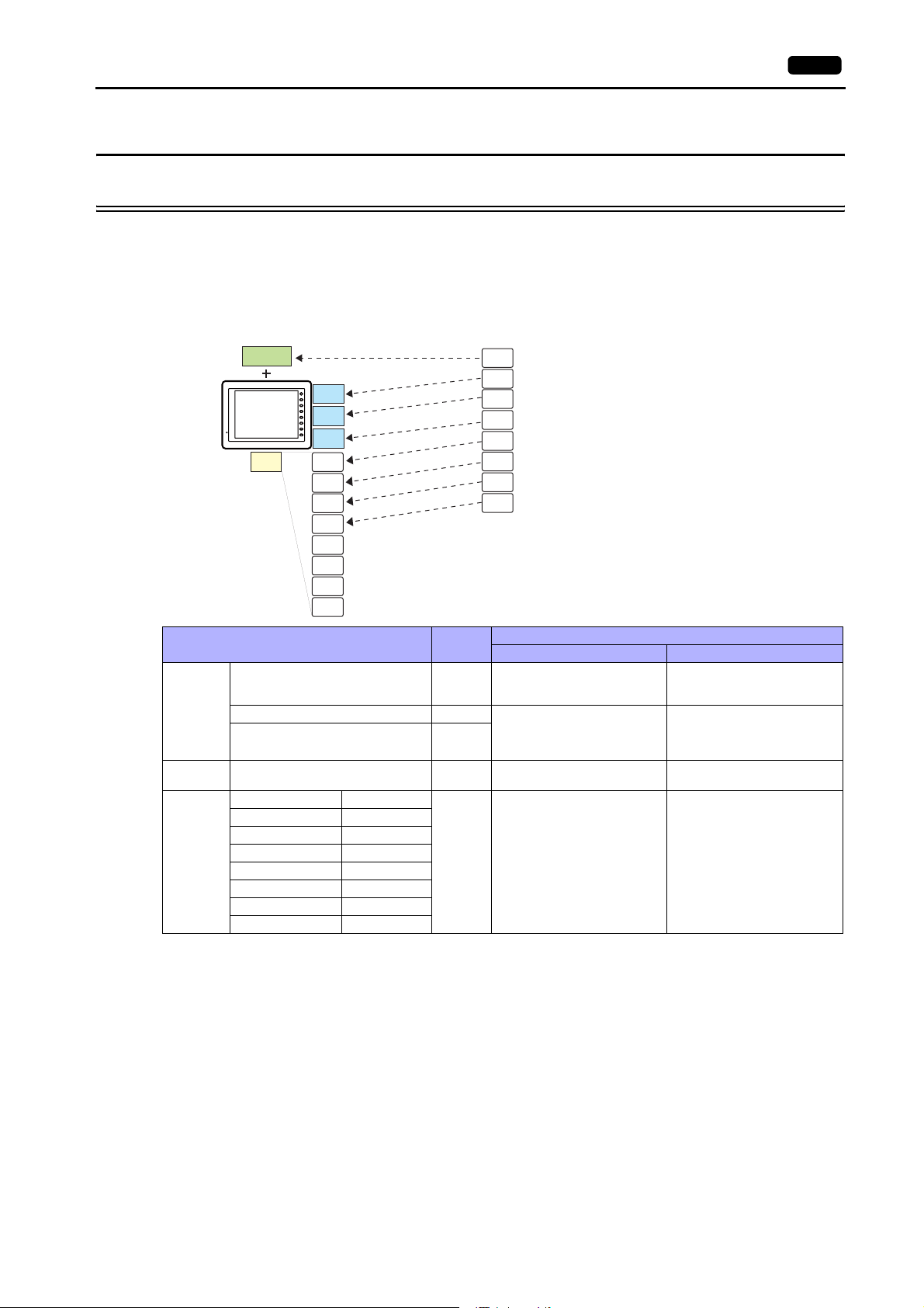
1.1 8-way Communication
1.1.1 Overview
1.1 8-way Communication 1-1
The V8 series is equipped with five physical ports consisting of three serial ports, one LAN port, and one network
communication port
*1
. The LAN port can open eight ports simultaneously. You can use the physical ports to connect a
maximum of eight different models of devices and allow the V8 series to communicate with them at the same time. This is
called the 8-way communication.
*1 A communication interface unit (CU-xx) is required to enable network communication.
Physical ports
CU-xx
V8
LAN
SYSTEM
CN1
F 1
F 2
F 3
F 4
MJ1
F 5
F 6
F 7
MJ2
port1
port2
port3
port4
Select a target for connection.
Logical ports
PLC1
PLC2
PLC3
PLC4
PLC5
PLC6
PLC7
PLC8
PLC (company A)
Temperature controller (company B)
Inverter (company C)
Barcode reader (company D)
PLC (company E)
PLC (company F)
PLC (company G)
PLC (company H)
port5
port6
port7
port8
Physical Ports
No. of
Ports
CN1 1
8-way Communication Other than 8-way
PLC/temperature
controller/servo/inverter/barcode
Applicable Devices
-
reader
Serial
Ethernet LAN 8
MJ1 1 PLC/temperature
controller/servo/inverter/barcode
MJ2 1
reader/V-Link/slave
communication (Modbus RTU)
PLC/slave communication
(Modbus TCP/IP)
Serial printer
CREC
V-I/O
-
OPCN-1 CU-00
T-Link CU-01
CC-Link CU-02-2
Network
Ethernet CU-03-3
PROFIBUS-DP CU-04
1PLC -
SX BUS CU-06
DeviceNet CU-07
FL-Net CU-08
• Only the logical port PLC1 can be selected for the following devices and functions. Thus, they cannot be connected at
the same time.
-Devices
- Network connection (CU-xx), without PLC connection, Mitsubishi Electric A-Link + Net10, AB Control Logix, Siemens
S7-200PPI, Siemens S7-300/400 MPI connection
- Functions
Multi-link2,
multi-link, ladder transfer, ladder monitor, Micrex SX variable name cooperation function
Page 26
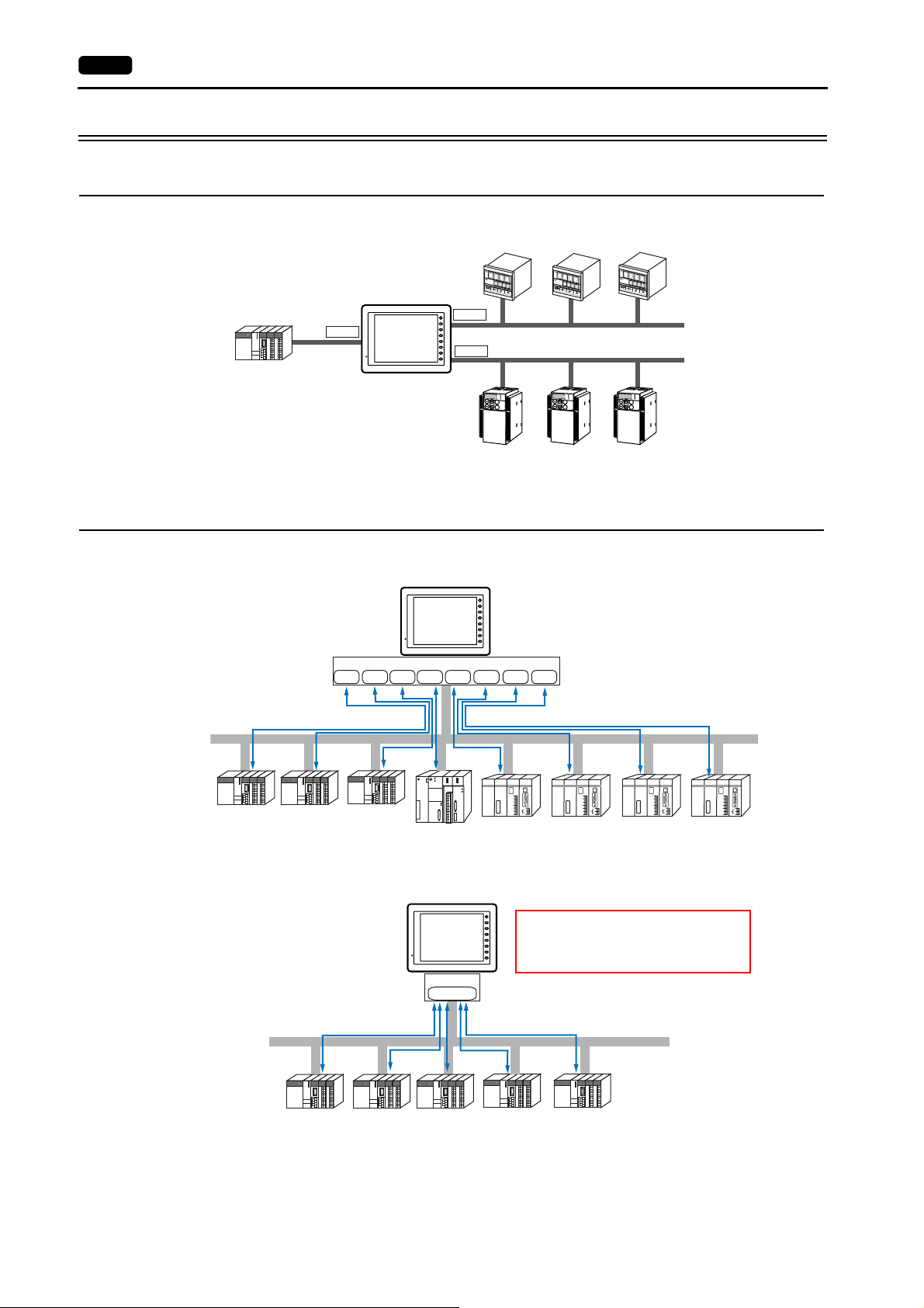
1-2 1. Overview
1.1.2 System Composition
Serial Communication
The V8 series is allowed to communicate with three different models of devices at the same time via three serial ports. A
maximum of 31 units of the same model can be connected to each port.
31 units
maximum
CN1
V8
31 units
MJ1
SYSTEM
F 1
F 2
F 3
F 4
F 5
F 6
MJ2
F 7
K
E
Y
P
A
K
E
Y
P
A
D
Hz
C
O
N
T
R
O
L
A
P
R
O
M
O
D
E
KW
PRG
R
E
S
E
T
R
U
N
FUNC
D
A
T
A
S
T
O
P
Inve
r
ter
D
Hz
C
O
N
T
R
O
L
A
P
R
O
M
O
D
E
KW
PRG
R
E
S
E
T
R
U
N
FU
NC
D
A
T
A
S
T
O
P
Inverte
r
PRG
R
E
S
E
T
FUNC
D
A
T
A
Inve
maximum
K
E
Y
P
A
D
Hz
C
O
N
T
R
O
L
A
P
R
O
M
O
DE
KW
R
U
N
S
T
O
P
31 units
r
ter
maximum
Ethernet Communication
Because eight communication ports can be opened, the V8 series is allowed to communicate with eight models of PLCs at
the same time.
Company A Company B Company C
When there are two or more PLCs of the same model, the V8 series is allowed to carry out 1 : n communication via one port.
SYSTEM
F 1
F 2
F 3
V8
F 4
F 5
F 6
F 7
LAN
Port2Port1 Port3 Port4 Port5 Port6 Port7 Port8
run
・・・
・・・
・・・
・・・
・・・
・・・
・・・
・・・
・・・
・・・
・・・
・・・
stop
・・・
・・・
・・・
・・・
PROGRAMMER
Company D
Company E Company F Company G Company H
SYSTEM
F 1
A maximum of 256 units can be connected to
F 2
F 3
V8
one port.*
F 4
F 5
In the case of TCP/IP communication, 64 units
F 6
F 7
in total can be connected to the eight ports.
LAN
Port1
Ethernet
PROGRAMMER
PROGRAMMER
PROGRAMMER
Ethernet
Company A
* V-SFT version 5.4.0.0 and later, system program version 1.400 and later: Max. 256 units connectable per port
V-SFT version earlier than 5.4.0.0, system program version earlier than 1.400: Max. 100 units connectable per port
Page 27
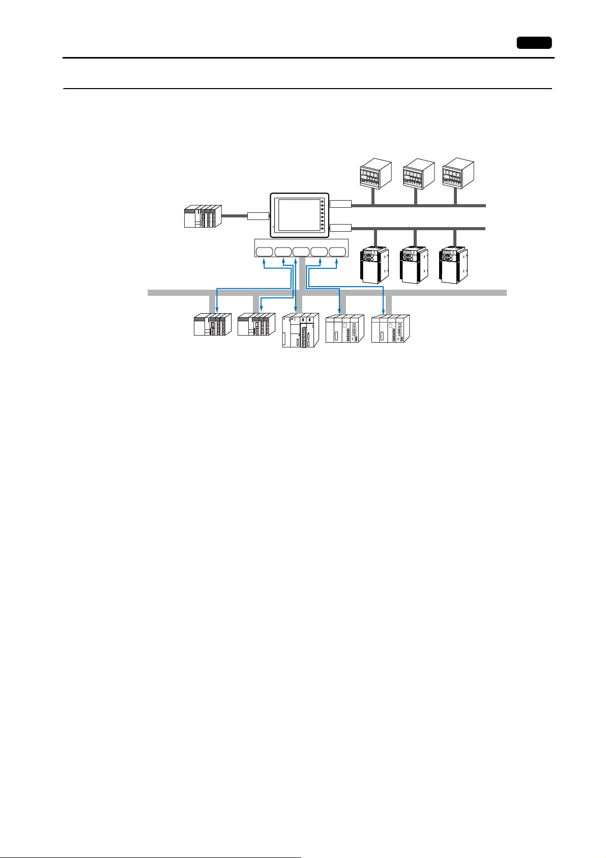
Mixed Serial-Ethernet Communication
In the case of mixed serial-Ethernet communication, the V8 series is allowed to communicate with eight different models of
devices at the same time.
• Connection of 3 models for serial communication and 5 models for Ethernet communication
CN1
Company A Company B
SYSTEM
F 1
MJ1
F 2
F 3
V8
F 4
F 5
F 6
F 7
MJ2
LAN
Port2Port1 Port3 Port4 Port5
run
・・・
・・・
・・・
・・・
・・・
・・・
・・・
・・・
・・・
・・・
・・・
・・・
stop
・・・
・・・
・・・
・・・
PROGRAMMER
Company C
Company D
K
E
Y
P
A
D
H
z
C
O
N
T
R
O
L
A
P
R
O
M
O
D
E
KW
PRG
R
E
S
E
T
R
U
N
FUNC
D
A
T
A
S
T
O
P
Inverte
r
Company E
1.1 8-way Communication 1-3
K
E
Y
P
A
D
H
z
C
O
N
T
R
O
L
A
P
R
O
M
O
D
E
K
W
PRG
R
E
S
E
T
R
U
N
FUNC
D
A
T
A
S
T
O
P
Inver
ter
PROGRAMMER
K
E
Y
P
A
D
H
z
C
O
N
T
R
O
L
A
P
RO
M
O
D
E
KW
PRG
R
E
S
E
T
R
U
N
FU
N
C
D
A
T
A
S
T
O
P
Inve
r
ter
Ethernet
Page 28
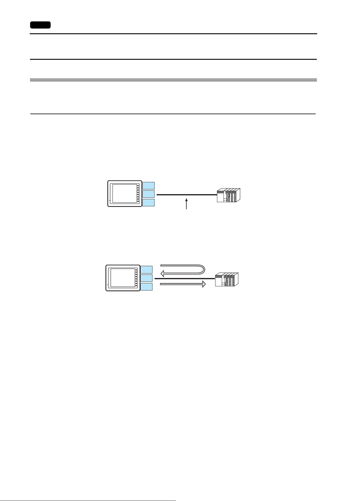
1-4 1. Overview
1.2 Connection Modes
1.2.1 PLC Connection
The V8 unit(s) can communicate with PLC(s) in serial, Ethernet, or network communication.
Serial Communication
There are four connection modes below to establish serial communication.
1 : 1 Connection
Overview
• One set of the V8 is connected to one PLC (1 : 1 connection).
• You can make settings for 1 : 1 communication in the [Communication Setting] tab window for the logical ports PLC1 -
PLC8. A communication port is selectable from CN1, MJ1, and MJ2.
PLC
V8
SYSTEM
CN1
F 1
F 2
F 3
F 4
MJ1
F 5
F 6
F 7
MJ2
RS-232C or RS-422 (RS-485) connection
• The V8 (master station) communicates with a PLC under the PLC’s protocol. Therefore, there is no need to prepare a
communication program for the PLC (slave station).
• The V8 reads the PLC memory for screen display. It is also possible to write switch data or numerical data entered
through the keypad directly to the PLC memory.
Read
PLC
V8
SYSTEM
CN1
F 1
F 2
F 3
F 4
MJ1
F 5
F 6
F 7
MJ2
Write
Connection
For more information on connection, see “1.4 Wiring” on page 1-18, “1.5 Settings for the Connected Device” on page 1-26, or
the chapters on individual manufacturers.
Page 29
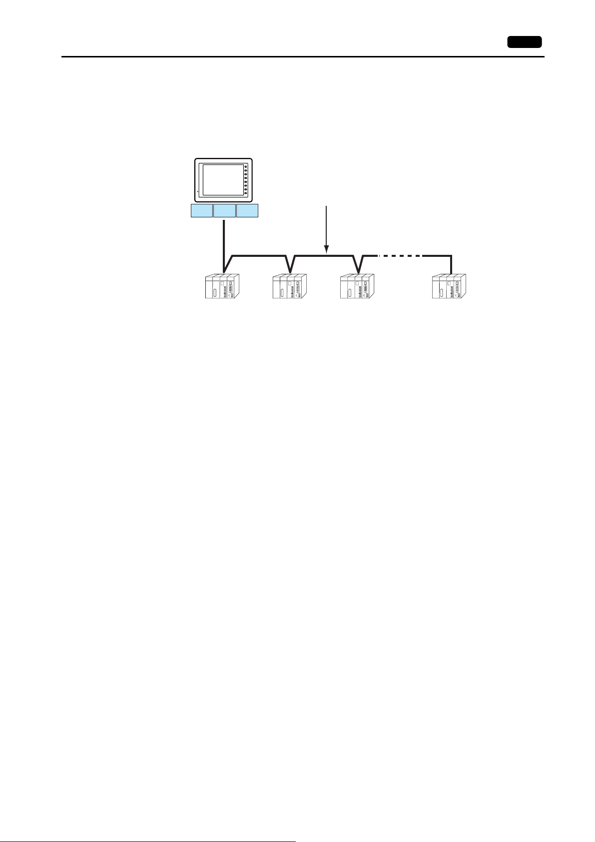
1 : n Connection (Multi-drop)
Overview
• Multi-drop connection connects one V8 unit to multiple PLCs of the same model as 1 : n connection. (Maximum
connectable PLCs: 31)
• You can make settings for 1 : n communication in the [Communication Setting] tab window for the logical ports PLC1 -
PLC8. A communication port is selectable from CN1, MJ1, and MJ2.
SYSTEM
F 1
F 2
F 3
V8
F 4
F 5
F 6
F 7
CN1 MJ1 MJ2
1.2 Connection Modes 1-5
Maximum length (V8 to the terminating PLC) = 500 m
RS-422/RS-485 connection
PLC (company A)
FACTORY
ACE
PROGRAMMER
FACTORY
ACE
PROGRAMMER
FACTORY
ACE
PROGRAMMER
FACTORY
ACE
PROGRAMMER
123 31
• For models that support multi-drop connection, refer to the list provided at the end of this manual or the chapters on
individual manufacturers.
Connection
For more information on connection, see “1.4 Wiring” on page 1-18, “1.5 Settings for the Connected Device” on page 1-26, or
the chapters on individual manufacturers.
For description of connecting the PLCs, refer to the manual for the corresponding PLC model.
Page 30
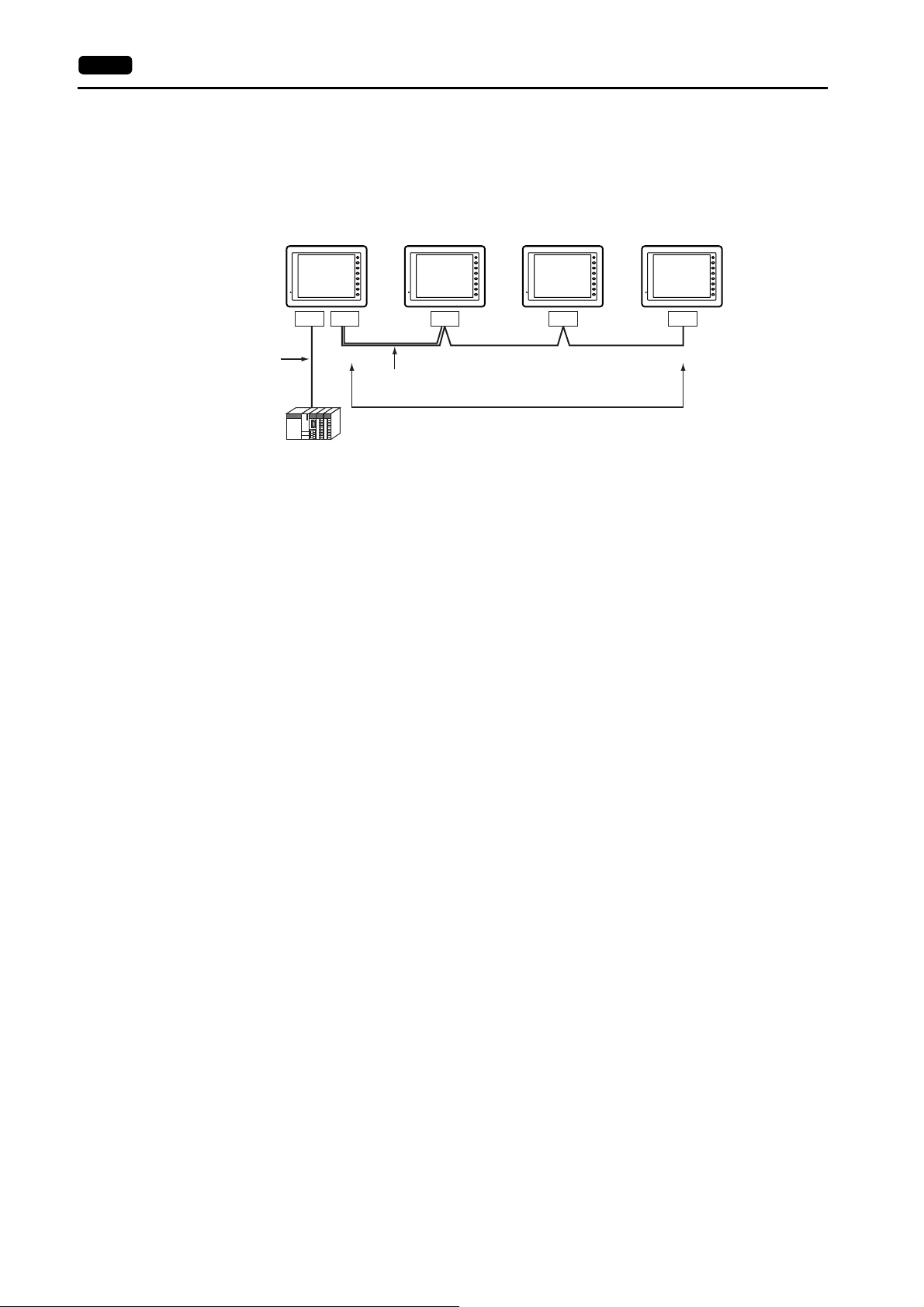
1-6 1. Overview
n : 1 Connection (Multi-link2)
Overview
• One PLC is connected to a maximum of four V8 units.
• Multi-link2 enables you to establish an original network consisting of a master V8 of local port No. 1 and slave V8 units of
local port Nos. 2, 3, and 4. The master V8 communicates with the PLC directly, and the slave V8 units communicate with
the PLC through the master.
Master
Local port 1
SYSTEM
F 1
F 2
F 3
F 4
F 5
F 6
F 7
Local port 2
Slave
SYSTEM
F 1
F 2
F 3
F 4
F 5
F 6
F 7
Local port 3
Slave
SYSTEM
F 1
F 2
F 3
F 4
F 5
F 6
F 7
Local port 4
Slave
SYSTEM
F 1
F 2
F 3
F 4
F 5
F 6
F 7
CN1 MJ2 CN1 CN1 CN1
RS-232C
RS-422
RS-485
Hakko Electronics’ cable “V6-MLT” (3 m)
RS-485 (2-wire system) connection
PLC
• You can make settings for multi-link2 in the [Communication Setting] tab window for the logical port PLC1. In the case of,
for example, network connection that uses the communication interface unit “CU-xx”, this type of connection is available
only with PLC1. Therefore, any device used for network connection cannot be connected concurrently for multi-link2.
• A communication port is selectable from CN1, MJ1, and MJ2.
• Multi-link2 enables PLC1 memory data to be shared among the V8 units. However, sharing data of PLC2 - PLC8 is not
possible.
• The V7 and V6 series cannot be used together.
* The V7 and V6 series can be connected together with some PLC models. For more information on the available PLC
models, refer to page App4-10.
• The communication speed between the master station and the PLC depend on the setting made on the PLC. The
maximum communication speed between V8 units is 115 kbps, which is higher than the one available with multi-link
connection described in “ n : 1 Connection (Multi-link)”.
• For PLCs that support multi-link2 connection, refer to the list provided at the end of this manual or the chapters on
individual manufacturers.
How to connect a master V8 and a PLC is the same as the method of 1 : 1 connection.
RS-485 (2-wire system) connection is adopted to connect a master with slaves. At this time, use Hakko Electronics’
cable “V6-MLT” for multi-link2 master.
Connection
For more information, see “Appendix 4.1 Multi-link2”.
Page 31

n : 1 Connection (Multi-link2 (Ethernet))
Overview
• One PLC is connected to a maximum of 32 units of the V8 series.
• Multi-link2 (Ethernet) enables you to establish an original network consisting of a master V8 of local port No. 1 and slave
V8 units of local port Nos. 2 to 32. The master V8 communicates with the PLC directly, and the slave V8 units
communicate with the PLC through the master.
- Connection example
1.2 Connection Modes 1-7
Master
Local port 1
SYSTEM
F 1
F 2
F 3
F 4
F 5
F 6
F 7
Local port 2
Slave
SYSTEM
F 1
F 2
F 3
F 4
F 5
F 6
F 7
Local port 3
Slave
SYSTEM
F 1
F 2
F 3
F 4
F 5
F 6
F 7
Local port 32
Slave
SYSTEM
F 1
F 2
F 3
F 4
F 5
F 6
F 7
LAN LAN LAN LANCN1
MJ1/MJ2
RS-232C
Ethernet
RS-422
RS-485
PLC
• You can make settings for multi-link2 (Ethernet) in the [Communication Setting] tab window for PLC1. Therefore,
multi-link2 (Ethernet) connection is not possible concurrently with a network connection that uses a “CU-xx”
communication interface unit.
• Multi-link2 (Ethernet) enables PLC1 memory data to be shared among the V8 units. However, sharing data of PLC2 -
PLC8 is not possible.
• The V7 and V6 series cannot be used together.
• The communication speed between the master station and the PLC depends on the setting made on the PLC; however,
communication among V8 units is performed via Ethernet, thus, high-speed communication is possible among them.
• For PLCs that support multi-link2 (Ethernet) connection, see the list provided at the end of this manual.
The method for connecting a master V8 and a PLC is the same as that for 1 : 1 connection.
Ethernet connection is adopted to connect a master with slaves.
Connection
For more information, see “Appendix 4.2 Multi-link2 (Ethernet)”.
Page 32

1-8 1. Overview
n : n Connection (1 : n Multi-link2 (Ethernet))
Overview
• A maximum of 32 units of the V8 series can be connected to a maximum of 31 units of PLCs.
• 1 : n multi-link2 (Ethernet) enables you to establish an original network consisting of a master V8 of local port No. 1 and
slave V8 units of local port Nos. 2 to 32. The master V8 communicates with the PLC directly, and the slave V8 units
communicate with the PLC through the master.
Master
Local port 1
SYSTEM
F 1
F 2
F 3
F 4
F 5
F 6
F 7
Local port 2
Slave
SYSTEM
F 1
F 2
F 3
F 4
F 5
F 6
F 7
Local port 3
Slave
SYSTEM
F 1
F 2
F 3
F 4
F 5
F 6
F 7
Local port 32
Slave
SYSTEM
F 1
F 2
F 3
F 4
F 5
F 6
F 7
LAN LAN LAN LANCN1
MJ1/MJ2
RS-422
Ethernet
RS-485
FACTORY
ACE
PROGRAMMER
FACTORY
ACE
PROGRAMMER
FACTORY
ACE
PROGRAMMER
FACTORY
ACE
PROGRAMMER
123 31
• You can make settings for 1 : n multi-link2 (Ethernet) in the [Communication Setting] tab window for PLC1. Therefore,
multi-link2 (Ethernet) connection is not possible concurrently with a network connection that uses a “CU-xx”
communication interface unit.
• 1 : n multi-link2 (Ethernet) enables PLC1 memory data to be shared among the V8 units. However, sharing data of PLC2
- PLC8 is not possible.
• The V7 and V6 series cannot be used together.
• The communication speed between the master station and the PLC depends on the setting made on the PLC; however,
communication among V8 units is performed via Ethernet, thus, high-speed communication is possible among them.
• For PLCs that support 1 : n multi-link2 (Ethernet) connection, see the list provided at the end of this manual.
The method for connecting a master V8 and a PLC is the same as that for 1 : n connection.
Ethernet connection is adopted to connect a master with slaves.
Connection
For more information, see “Appendix 4.3 1 : n Multi-link2 (Ethernet)”.
Page 33

n : 1 Connection (Multi-link)
Overview
• One PLC is connected to a maximum of 31 V8 units. The V8, V7, and V6 series can be used together.
- Connection Example
1.2 Connection Modes 1-9
SYSTEM
F 1
F 2
Port No. 1 Port No. 2 Port No. 3 Port No. 31
F 3
F 4
F 5
F 6
F 7
SYSTEM
F 1
F 2
F 3
F 4
F 5
F 6
F 7
SYSTEM
F 1
F 2
F 3
F 4
F 5
F 6
F 7
SYSTEM
F 1
F 2
F 3
F 4
F 5
F 6
F 7
CN1 CN1 CN1 CN1
Maximum length (PLC to the terminating V8) = 500 m
RS-485 (2-wire system) connection
PLC1
• You can make settings for multi-link using the logical port PLC1. For the V8, a communication port is selectable from
CN1, MJ1, and MJ2. For the V7 or V6, however, use CN1 only.
• Only a PLC for the signal level RS422/RS485 and with a port number is available. For PLCs that support multi-link
connection, refer to the list provided at the end of this manual or the chapters on individual manufacturers.
• RS-485 (2-wire system) connection is adopted to connect a V-series unit and a PLC.
Connection
For more information, see “Appendix 4.4 Multi-link”.
Page 34

1-10 1. Overview
Ethernet Communication
Overview
• Because eight communication ports can be opened, the V8 series is allowed to communicate with eight models of PLCs
at the same time.
Company A Company B Company C
• When there are two or more PLCs of the same model, the V8 series is allowed to carry out 1 : n communication via one
single port.
SYSTEM
F 1
F 2
F 3
V8
F 4
F 5
F 6
F 7
LAN
Port2Port1 Port3 Port4 Port5 Port6 Port7 Port8
run
・・・
・・・
・・・
・・・
・・・
・・・
・・・
・・・
・・・
・・・
・・・
・・・
stop
・・・
・・・
・・・
・・・
PROGRAMMER
Company D
Company E Company F Company G Company H
Ethernet
PROGRAMMER
PROGRAMMER
PROGRAMMER
SYSTEM
F 1
A maximum of 256 units can be connected to
F 2
F 3
V8
one port.*
F 4
F 5
In the case of TCP/IP communication, 64 units
F 6
F 7
in total can be connected to the eight ports.
LAN
Port1
Ethernet
Company A
* V-SFT version 5.4.0.0 and later, system program version 1.400 and later: Max. 256 units connectable per port
V-SFT version earlier than 5.4.0.0, system program version earlier than 1.400: Max. 100 units connectable per port
• If multiple V8 units are connected to one single PLC, the maximum permissible number of these units depends on the
PLC specifications. Refer to the PLC manual issued by the manufacturer.
Ethernet
FACTORY
ACE
PROGRAMMER
IP192.168.1.10
PLC
Port1
LAN
SYSTEM
F 1
F 2
V8 V8 V8
F 3
F 4
IP192.168.1.1 IP192.168.1.2 IP192.168.1.3
F 5
F 6
F 7
Port1
LAN
Port1
LAN
SYSTEM
F 1
F 2
F 3
F 4
F 5
F 6
F 7
SYSTEM
F 1
F 2
F 3
F 4
F 5
F 6
F 7
• You can make settings for Ethernet communication in the [Communication Setting] tab window for the logical ports PLC1
- PLC8.
Connection
For more information, see “Appendix 2 Ethernet”.
Page 35

Network Communication
Overview
• An appropriate communication interface unit is required to enable a network communication listed below.
Communication Interface Unit Network Models
CU-00
CU-01 T-Link
CU-02
CU-03-3 Ethernet
CU-04 PROFIBUS-DP
CU-06 SX BUS Fuji Electric MICREX SX(SX bus)
*1
CU-07
CU-08
*1 The driver is under development.
*2 Besides communicating with PLC via UDP/IP, data transfer, MES interface function and TELLUS and V-Server can be supported
by connecting to a PC. Use built-in Ethernet port when communicating on TCP/IP.
• You can make settings for network communication in the [Communication Setting] tab window for the logical port PLC1.
Thus, devices available with only PLC1, as those used for multi-link or multi-link2, cannot be connected concurrently for
network communication.
1.2 Connection Modes 1-11
OPCN-1 Fuji Electric MICREX SX(OPCN-1)
Fuji Electric MICREX F(T-LINK)
Fuji Electric MICREX SX(T-LINK)
CC-Link version 1.10
*2
DeviceNet -
FL-Net FL-Net
MITSUBISHI ELECTRIC A series(CC-LINK)
MITSUBISHI ELECTRIC QnA series(CC-LINK)
MITSUBISHI ELECTRIC QnH series(CC-LINK)
PLC Ethernet connection(UDP/IP)
Siemens S7 PROFIBUS-DP
PROFIBUS-DP
Connection
For more information, refer to the communication unit specifications provided for each network.
Page 36

1-12 1. Overview
1.2.2 Temperature Controller/Servo/Inverter Connection
The V8 series is connected to temperature controllers, servos, or inverters via serial communication.
Serial Communication
1 : n Connection
Overview
• The V8 series is connected to multiple temperature controllers, servos, or inverters of the same model as 1 : n
connection. (Maximum connectable units: 31)
• You can make settings for temperature controller/servo/inverter communication in the [Communication Setting] tab
window for the logical ports PLC1 - PLC8. RS-422 (4-wire system) connection is available only by using CN1 or MJ2 on
V806. To establish a connection via RS-422 (4-wire system), use CN1 or MJ2 on the V806.
SYSTEM
F 1
F 2
F 3
V8
F 4
F 5
F 6
Maximum length (V8 to the terminating device) = 500 m
F 7
CN1 MJ1 MJ2
RS-485 (2-wire system) connection
Temperature controller
(company A)
123 31
Connection
For more information on connection, see “1.4 Wiring” on page 1-18, “1.5 Settings for the Connected Device” on page 1-26, or
the chapters on individual manufacturers.
1.2.3 Barcode Reader Connection
The V8 series is connected to a barcode reader in serial communication.
Serial Communication
Overview
• The V8 series is connected to a barcode reader as 1 : 1 connection (RS-232C).
• You can make settings for barcode reader communication in the [Communication Setting] tab window for the logical ports
PLC2 - PLC8. A communication port is selectable from CN1, MJ1, and MJ2.
SYSTEM
F 1
Code No.
4902580302474
F 2
F 3
F 4
F 5
F 6
F 7
CN1
MJ1
MJ2
49025803024
PI !
4
7
RS-232C
Connection
For more information on connection, see “62.1 Barcode Reader Connection”.
Page 37

1.2.4 Slave Communication
Connecting via V-Link, Modbus RTU, or Modbus TCP/IP is applicable to slave communication using the V8. V-Link and
Modbus RTU are used for serial communication, and Modbus TCP/IP is used for Ethernet (TCP/IP) communication.
V-Link
• “V-Link” is the network where the computer reads from and writes to the internal memory of the V8 series, memory card,
or PLC1 to 8 memory using a dedicated protocol.
Dedicated commands
Read
Write
1.2 Connection Modes 1-13
SYSTEM
F 1
F 2
F 3
F 4
F 5
F 6
F 7
• You can make settings for V-Link in the [Communication Setting] tab window for the logical ports PLC2 - PLC8. A
communication port is selectable from CN1, MJ1, and MJ2.
• For more information, see “63.1 V-Link”.
Modbus RTU
• The V8 series is connected to a Modbus RTU master via serial connection.
• The Modbus slave communication memory table is prepared for the V8. The master is allowed to gain access to the
memory table and read/write the PLC data.
• For more information, refer to the Modbus Slave Communication manual separately provided.
Modbus TCP/IP
• The V8 is connected to a Modbus TCP/IP master via Ethernet communication.
• The Modbus slave communication memory table is prepared for the V8. The master is allowed to gain access to the
memory table and read/write the PLC data.
• For more information, refer to the Modbus Slave Communication manual separately provided.
V8 series
PLCPC
1.2.5 Other Connections
For connection to a V-I/O, a CREC, or a serial printer that is not in 8-way communication, serial ports of MJ1 and MJ2 are
used.
Page 38

1-14 1. Overview
1.3 Physical Port
* For details on the V808CH’s terminal block (TB), refer to the V808CH Hardware Specifications manual.
1.3.1 CN1
The CN1 port supports communication via RS-232C, RS-422 (4-wire system), and RS-485 (2-wire system). The signal level
can be changed between RS-232C and RS-422/485 on the [Communication Setting] tab window of the editor.
When executing communication via RS-232C, set the DIP switches 5 and 7 to OFF. (For more information on the DIP
switch, refer to the separate V8 Series Hardware Specifications manual.)
Pin Arrangement
CN1
D-sub 9-pin,
Female
5
9
6
1
No.
Signal Contents Signal Contents
1 NC Not used +RD Receive data (+)
2 RD Receive data −RD Receive data (−)
3 SD Send data −SD Send data (−)
4 NC Not used +SD Send data (+)
5 0V Signal ground 0V Signal ground
6 NC Not used +RS RS send data (+)
7 RS RS request to send −RS RS send data (−)
8 CS CS clear to send NC Not used
9 NC Not used +5 V Terminating resistance
RS-232C RS-422/RS-485
Recommended Connector for Communication Cable
Recommended Connector
DDK’s 17JE-23090-02(D8C)-CG D-sub 9-pin, male, inch screw thread, with hood, RoHS compliant
Applicable Devices
Applicable Devices
PLC, temperature controller, inverter, servo, barcode reader
Page 39

1.3.2 MJ1/MJ2
The MJ1 and MJ2 ports support communication via RS-232C, RS-422 (4-wire system)*1 and RS-485 (2-wire system).
MJ1 is also usable as a screen data transfer port.
*1 MJ2 on V806 only
Pin Arrangement
MJ1 (All Models) / MJ2 (V815/V812/V810/V808)
1.3 Physical Port 1-15
MJ1/MJ2
RJ-45 8-pin
12345678
No. Signal Contents
1 +SD/RD RS-485 + data
2 −SD/RD RS-485 − data
3
4
5
6
7 RD RS-232C receive data
8 SD RS-232C send data
+5 V
SG Signal ground
Externally supplied +5 V *
Max. 150 mA
MJ2 (V806)
Before using MJ2, select whether it is used as an RS-232C/RS-485 (2-wire system) or RS-422
CAUTION
MJ2
RJ-45 8-pin
12345678
* Allowable current for the external power supply +5 V:
For MJ1 and MJ2, the maximum allowable current is 150 mA in total.
When connecting an optional unit or communication unit, be careful not to exceed the total allowable current for USB-A, MJ1 and MJ2.
Extension Unit Communication Unit (CU-xx)
GU-00 - GU-03
GU-10, GU-11
(4-wire system) port using the slide switch.
The switch is factory-set to RS-232C/RS-485 (2-wire system).
No.
1 +SD/RD RS-485 + data +SD RS-422 + send data
2 −SD/RD RS-485 − data −SD RS-422 − send data
3
4
5
6
7 RD RS-232C receive data +RD RS-422 + receive data
8 SD RS-232C send data −RD RS-422 − receive data
None
Slide Switch (RS-232C/RS-485) Slide Switch (RS-422)
Signal Contents Signal Contents
+5 V
SG Signal ground SG Signal ground
Externally supplied +5 V *
Max. 150 mA
None
None
Provided 550 mA
None 650 mA
Provided 250 mA
+5V
Maximum Allowable Current
for MJ1 + MJ2 + USB
650 mAProvided
Externally supplied +5 V *
Max. 150 mA
Recommended Cable
Hakko Electronics’ cable “V6-TMP” 3, 5, 10 m
Recommended Cable
Page 40

1-16 1. Overview
Notes on Configuring a Cable
CAUTION
Applicable Devices
Port Applicable Devices
MJ1
MJ2
Pins No. 3 and 4 are provided for external power supply. To prevent damage to the device due to wrong
connection, check the pin numbers and connect wires correctly.
Pin arrangement
on MONITOUCH
87654321
SYSTEM
F 1
F 2
F 3
F 4
F 5
F 6
F 7
Computer (screen data transfer)
PLC, temperature controller, inverter, servo, barcode reader, V-Link, slave communication (Modbus RTU), serial printer,
CREC, V-I/O
PLC, temperature controller, inverter, servo, barcode reader, V-Link, slave communication (Modbus RTU), serial printer,
CREC, V-I/O
Pin arrangement
on the cable
12345678
Page 41

1.3.3 LAN
LAN Port Specifications
1.3 Physical Port 1-17
Item
100BASE-TX (IEEE802.3u) 10BASE-T (IEEE802.3)
Specifications
Baud Rate 100 Mbps 10 Mbps
Transmission Method Base band
Maximum Node Interval
*2
(Cascading connection via repeater
200 m
hubs: 2 stages)
(Cascading connection via repeater
500 m
hubs: 4 stages)
Maximum Segment Length 100 m (between the node and the hub)
Connecting Cable 100Ω, UTP cable, category 5
Protocol
Number of concurrently opened
*3
ports
Maximum number of connectable
*3
devices
Maximum number of connectable
devices (TCP/IP)
*1 For connection with some PLCs
*2 No limitation for a switching hub
*3
UDP/IP, TCP/IP
8 ports
256 sets each via one single port PLC1 - PLC8
64 sets in total via PLC1 - PLC8
*1
*3 See the figure shown below.
No.0
Company A
256 sets
(Screen data registered in
No.1
the PLC table)
No.99
During TCP/IP
communication,
communicating with up
to 64 sets in total is
possible via 8 ports.
No.0
Company B
256 sets
(Screen data registered in
the PLC table)
No.99
*4
*4
V8i
Number of ports
8
Port1
Port2
SYSTEM
F 1
F 2
Port3
F 3
F 4
LAN
F 5
F 6
F 7
Port8
PROGRAMMER
PROGRAMMER
*4
*4 V-SFT version 5.4.0.0 and later, system program version 1.400 and later:Max. 256 units connectable per port
V-SFT version earlier than 5.4.0.0, system program version earlier than 1.400:Max. 100 units connectable per port
Pin Arrangement
LAN
RJ45
12345678
No. Signal Contents
Applicable Devices
Applicable Devices
PLC, slave communication (Modbus TCP/IP), computer (screen data transfer, V-Server, etc.)
1.3.4 Network Communication Port
An optional communication interface unit (CU-xx) is required to perform network communication.
For more information, refer to the specifications for each unit.
1 TX+ Send signal +
2TX− Send signal −
3 RX+ Receive signal +
4
5
NC Not used
6RX− Receive signal −
7
8
NC Not used
Page 42

1-18 1. Overview
1.4 Wiring
This section provides notes on configuring cables. For device wiring diagrams, refer to the chapters on individual
manufacturers.
1.4.1 CN1 Connection
DANGER
Be sure to turn off the power before connecting cables. Otherwise, electrical shock or damage may occur.
RS-232C Connection
• Prepare a communication cable on your side. Twisted pairs of 0.3 mm sq. or above are recommended.
• Connect a shielded cable to either the V8 series or the connected device. The connection diagram shows the case
where the shielded cable is connected on the V8 series side. Connect the cable to the FG terminal on the backside of
MONITOUCH.
CN1
Dsub 9 (Male)
6
9
• If noise disturbs communications, establish connections between SD and SG and between RD and SG as pairs
respectively, and connect a shielded cable to both the V8 series and the connected device.
CN1
Dsub 9 (Male)
6
9
RS-232C port of the
No.Name
Shield
connected device
FG
RD
1
SD
5
SG
RS
CS
2
3
5
7
8
No.Name
Shield
FG
RD
1
SD
5
SG
2
3
5
Send data
Receive data
SG
RS-232C port of the
connected device
FG
Receive data
SG
SG
Send data
RS
CS
7
8
Page 43

RS-422/485 Connection
• Prepare a communication cable on your side. Twisted pairs of 0.3 mm sq. or above are recommended.
• Connect twisted pairs between +SD/−SD and +RD/−RD.
• If the PLC has the terminal for signal ground (SG), connect a wire.
• To use a terminal block for connection, use Hakko Electronics’ “TC-D9” optionally available.
• The DIP switch on the back of the V8 unit is used to set the terminating resistance. For more information on the DIP
switch, refer to the separate V8 Series Hardware Specifications manual.
• Connect a shielded cable to either the V8 series or the connected device. The connection diagram shows the case
where the shielded cable is connected on the V8 series side. Connect the cable to the FG terminal on the backside of
MONITOUCH.
- RS-422 (4-wire system)
CN1
Dsub 9 (Male)
6
9
1
5
Name
FG
+RD
-RD
-SD
No.
1
2
3
1.4 Wiring 1-19
RS-422 port of the
connected device
Shield
Send data (+)
Send data (−)
Receive data (−)
+SD
- RS-485 (2-wire system)
CN1
Dsub 9 (Male)
Name
FG
+RD
1
6
9
-RD
5
-SD
+SD
4
5SG SG
RS-485 port of the
No.
Shield
1
2
connected device
Send/receive data (+)
Send/receive data (−)
3
4
5SG SG
Receive data (+)
Page 44

1-20 1. Overview
• If noise disturbs communications, connect a shielded cable to both the V8 series and the connected device.
- RS-422 (4-wire system)
CN1
Dsub 9 (Male)
Name
FG
+RD
1
6
9
-RD
5
-SD
+SD
- RS-485 (2-wire system)
CN1
Dsub 9 (Male)
Name
FG
+RD
1
6
9
-RD
5
-SD
+SD
No.
Shield
1
2
3
4
5SG SG
No.
Shield
1
2
3
4
5SG SG
RS-422 port of the
connected device
FG
Send data (+)
Send data (−)
Receive data (−)
Receive data (+)
RS-485 port of the
connected device
FG
Send/receive data (+)
Send/receive data (−)
Multi-drop connection (1 : n)
In the case of multi-drop connection, wiring between a V8 and a connected device is the same as that for 1 : 1
communication. Meanwhile, for description of wiring between connected devices, refer to the manual issued by the
manufacturer.
• Connection example
CN1
Dsub 9 (Male)
Name
No.
FG
+RD
1
6
9
-RD
5
-SD
+SD
RD terminating resistance: ON
RS-422 port of the
connected device
FG
1
2
3
4
5SG
Send data (+)
Send data (−)
Receive data (−)
Receive data (+)
SG
For wiring between connected devices, refer to the
manual issued by the manufacturer.
RS-422 port of the
connected device
FG
Send data (+)
Send data (−)
Receive data (−)
Receive data (+)
SG
Page 45

1.4.2 MJ1/MJ2
CAUTION
RS-232C Connection
• Use Hakko Electronics’ cable “V6-TMP” (3, 5, 10 m) as a communication cable.
• Connect a shielded cable to either the V8 series or the connected device. Connect the cable to the FG terminal on the
backside of MONITOUCH.
MJ1/2
RJ - 45
12345678
1.4 Wiring 1-21
• Be sure to turn off the power before connecting cables. Otherwise, electrical shock or damage may occur.
• Pins No. 3 and 4 are provided for external power supply. To prevent damage to the device due to wrong
connection, check the pin numbers and connect wires correctly.
RS-232C port of the
connected device
Name
No.
Shield
FG
RD
SD
7
8
Receive data
Send data
SG
5
SG
• If noise disturbs communications, connect a shielded cable to both the V8 series and the connected device.
RS-232C port of the
MJ1/2
RJ - 45
12345678
Name
FG
RD
SD
SG
No.
7
8
5
Shield
connected device
FG
Receive data
Send data
SG
Page 46

1-22 1. Overview
RS-422/485 Connection
MJ2 on the V806 series can be used for connection via RS-422 (4-wire system). For the other models, MJ1 and MJ2
cannot be used for connection via RS-422 (4-wire system). Use the CN1 port instead or a RS-232C-to-RS-422 converter
commercially available.
• Use Hakko Electronics’ cable “V6-TMP” (3, 5, 10 m) as a communication cable.
• If the PLC has the terminal for signal ground (SG), connect a wire.
• The DIP switch on the back of the V8 unit is used to set the terminating resistance. For more information, refer to the
description of the DIP switch setting in the relevant Hardware Specifications manual.
• Connect a shielded cable to either the V8 series or the connected device. Connect the cable to the FG terminal on the
backside of MONITOUCH.
- RS-422 (4-wire system)
V806 MJ2
RJ - 45
Name
No.
FG
+RD
12345678
-RD
-SD
+SD
SG
* Slide switch on V806:
RS-422 (lower)
- RS-485 (2-wire system)
MJ1/2
RJ - 45
Name
FG
12345678
+RD/+SD
-RD/-SD
SG
RS-485 port of the
Shield
7
8
2
1
5
No.
Shield
1
2
5
connected device
Send data (+)
Send data (−)
Receive data (−)
Receive data (+)
SG
RS-485 port of the
connected device
Send/receive
data (+)
Send/receive
data (−)
SG
Page 47

1.4 Wiring 1-23
• If noise disturbs communications, connect a shielded cable to both the V8 series and the connected device.
- RS-422 (4-wire system)
V806 MJ2
RJ - 45
Name
No.
FG
+RD
12345678
-RD
-SD
+SD
SG
* Slide switch on V806:
RS-422 (lower)
- RS-485 (2-wire system)
MJ1/2
RJ - 45
Name
FG
12345678
+RD/+SD
-RD/-SD
SG
RS-485 port of the
Shield
connected device
FG
7
8
2
1
5
No.
Shield
Send data (+)
Send data (−)
Receive data (−)
Receive data (+)
SG
RS-485 port of the
connected device
FG
1
2
5
Send/receive
data (+)
Send/receive
data (−)
SG
Multi-drop connection (1 : n)
In the case of multi-drop connection, wiring between a V8 and a connected device is the same as that for 1 : 1
communication. Meanwhile, for description of wiring between connected devices, refer to the manual issued by the
manufacturer.
• Connection example
MJ1/2
RJ - 45
12345678
RD terminating resistance: ON
Name
FG
+RD/+SD
-RD/-SD
SG
No.
RS-485 port of the
connected device
1
2
5
Send/receive
data (+)
Send/receive
data (−)
SG SG
For wiring between connected devices, refer
to the manual issued by the manufacturer.
RS-485 port of the
connected device
Send/receive
data (+)
Send/receive
data (−)
Page 48

1-24 1. Overview
1.4.3 LAN
Connection Example
With hub
* Cascading connection via repeater hubs: 4 stages (2 stages) maximum
Without hub
Repeater hub
UTP straight cable
CU-03-3
SYSTEM
F 1
F 2
F 3
F 4
V8i V8
F 5
F 6
F 7
FACTORY
ACE
PROGRAMMER
Between hubs
100 m (5 m)
Between the node and the hub
100 m
SYSTEM
F 1
F 2
F 3
F 4
F 5
F 6
F 7
Numerals within parentheses:
applied to 100BASE-TX
Wiring Diagrams
• Use a commercially available cable. Using a self-made cable may cause an error in network connection.
• If the use of a cross cable cannot stabilize communication, use a hub.
• Straight cable
12345678 12345678
MJ1/2
RJ - 45
TX+
TX-
RX+
RX-
NC
NC
NC
NC
No.
SYSTEM
UTP cross cable
F 1
F 2
F 3
V8i
F 4
F 5
F 6
F 7
100 m
1
2
3
6
4
5
7
8
TX+
TX-
RX+
RX-
NC
NC
NC
NC
FACTORY
ACE
PROGRAMMER
MJ1/2
No.NameName
RJ - 45
1
2
3
6
4
5
7
8
Twist-pair cable
Page 49

• Cross cable
1.4 Wiring 1-25
MJ1/2
RJ - 45
12345678 12345678
TX+
TX-
RX+
RX-
NC
NC
NC
NC
No.
1
2
3
6
4
5
7
8
TX+
TX-
RX+
RX-
NC
NC
NC
NC
MJ1/2
No.NameName
RJ - 45
1
2
3
6
4
5
7
8
Twist-pair cable
Page 50

1-26 1. Overview
1.5 Settings for the Connected Device
1.5.1 PLC1 to PLC8
To enable communication with a PLC, a temperature controller, an inverter, etc., the following settings are required to be set
on the editor. You can see the contents of these settings on the V8 Main Menu screen.
For the Main Menu screen, refer to the separate V8 Series Hardware Specifications manual.
Selecting a Device to be Connected
Communication Setting
Connection Mode
Signal Level
Baud Rate
Data Length
Stop Bit
Parity
Target Port No.
*1
*1
*1
*1
*1
Select a connection mode.
1 : 1 / 1 : n / Multi-link / Multi-link2
Available options vary, depending on which device is connected. See the list at the end of this manual.
Select a signal level.
RS-232C / RS-422/485
Select a baud rate.
4800 / 9600 / 19200 / 38400 / 57600 / 76800 / 115K BPS
Select a data length.
7-Bit / 8-Bit
Select a stop bit.
1-Bit / 2-Bit
Select an option for parity bit.
None / Odd / Even
*1
Specify a port number of the connected device.
0 to 31 (Modbus RTU: 1 to 255)
Page 51

1.5 Settings for the Connected Device 1-27
Transmission Mode
*1
Time-out Time
Retrials
Send Delay Time
Start Time
Comm. Error Handling
Reset Condition
Code
Text Process
Select a transmission mode for the connected device.
This setting is required if a device of Mitsubishi, Omron, Hitachi Industrial Equipment Systems, Yokogawa,
JTEKT, or Yaskawa is in use.
Specify a period of time allowed for V8 to monitor a response from its connected device. If V8 receives no
response within the specified time, it retries to communicate with it.
0 to 999 (× 10 msec)
Specify the number of retrials to be allowed in the event of a timeout during communication. If a timeout
persists even after as many retrials as specified, an error handing routine will take place.
1 to 255
Specify a delay time that elapses before V8 sends the next command after receiving a response from its
connected device. Normally use the default setting.
0 to 255 (× 1 msec)
PLC
MONITOUCH
Send delay time “t”
Specify a delay time that elapses before V8 starts to send commands upon power-up. If V8 and its
connected device are turned on at the same time and the device is slower to start up, set [Start Time].
0 to 255 (× 1 sec)
Select an action to be taken in the event of a communication error.
• [Stop]
Communication will be stopped entirely and the communication error screen will be displayed. The
[RETRY] switch is available to retry the reestablishment of communication.
• [Continue]
The communication error message will be displayed in the top-left of the screen. The same
communication will continue until restoration, and screen operation is not allowed then. When
communication has been returned to a normal state, the message disappears and screen operation is
allowed.
• [Disconnect]
No error message will appear and communication will proceed to the next.
However, communication with the device, in which a timeout was detected, will be disconnected.
* Internal memory must be specified for [Read Area] and [Write Area].
*
This setting is valid when [Disconnect] is selected for [Comm. Error Handling].
• [ Return Time] 1 to 255 sec (× 10 sec)
When the specified time has elapsed, V8 checks the restoration of the device which discontinued
communicating.
• [ Auto-restoration upon screen switch-over]
When the screen is switched, V8 checks the restoration of the device which discontinued
communicating.
Select a code for the connected device. The selected option is reflected through the data displayed on
graphs or trending sampling parts.
DEC/BCD
Specify a byte order in text data. This setting is valid for macro commands that handle text.
LSB → MSB / MSB → LSB
[LSB → MSB]
[MSB → LSB]
15 0
MSB
LSB
2nd byte 1st byte
15 0
MSB
LSB
1st byte 2nd byte
*1 Be sure to match the settings to those made on the connected device.
Page 52

1-28 1. Overview
Detail
Priority
System memory ($s) V7
Compatible (PLC1)
System memory ($s) V7
Compatible (PLC2)
Transfer Table Control
Memory
Multi-link2 with V7/V6
Target Settings
[1] (higher priority) - [8] (lower priority)
Specify a priority taken during 8-way communication. If interrupts from two or more devices occur at the
same time, communication with these devices will take place in order of priority.
This box is checked if the V7-series screen data has been converted to the data for the V8 series. The
system information relevant to 8-way communication will be stored in memory $P1 and $s. For more
information, see “Appendix 3 System Memory” (page App3-1).
This box is checked if the V7-series screen data (including temperature control network/PLC2Way settings)
has been converted to the data for the V8 series.
• Unchecked
$P2:493/494/495 is used as the transfer table control memory.
• Checked
$s762/763/764 is used as the transfer table control memory.
For more information, see “Appendix 3 System Memory” (page App3-1).
Specify the transfer table control memory for PLC1 - PLC8.
The memory specified here is the same as [Control Memory] in the [Device Memory Map Setting] dialog
([System Setting] → [Device Memory Map] → [Device Memory Map Edit] window → [Device Memory Map
Setting] dialog).
For more information, see “ Control Memory” (page App1-11).
This box is checked when multi-link2 is used for connecting the V8 together with the V7 or V6.
Connection Check
Memory
Connect To
PLC Table
Specify a desired memory address used for connection confirmation when communication starts.
This memory address will be used mainly during Modbus communication.
Set these items for Ethernet communication. See “Appendix 2 Ethernet”.
Page 53

1.5.2 Read/Write Area
Read/Write Area
1.5 Settings for the Connected Device 1-29
Read Area
Specify a memory address used to give commands for display or operation from the PLC to MONITOUCH.
Three words (at the minimum)
*1
of consecutive memory addresses are secured.
For more information, see “ Read area” (page 1-29).
This is the area, to which the screen numbers or overlaps displayed on MONITOUCH or a buzzer state will
Write area
Calendar
be written. Three words of consecutive memory addresses are secured.
For more information, see “ Write area” (page 1-33).
*2
This setting is valid when the V8’s internal clock
The setting allows the calendar data to be read from the device via the selected port at PLC1 - PLC8.
The calendar data will be updated when:
• The power is turned on.
•STOP → RUN
• The date changes.
• Bit 11 in the read area “n” is set (ON) (0 → 1 leading edge)
is not used.
*1 More words are required if the sampling function is used:
sampling control memory (three words maximum), sampling data memory (variable depending on the setting)
*2 For more information on the internal clock, refer to the V8 Series Reference Manual.
Read area
The read area is the area where the PLC gives commands for display or operation to MONITOUCH.
Three words (at the minimum) of consecutive memory addresses are secured.
MONITOUCH always reads data from these three words to display and operate according to the commands.
“Display the ERROR screen.”
(a command is given.)
MONITORING
A-1 A-2 A-3 A-4 A-5
B-1 B-2 B-3 B-4 B-5
C-1 C-2 C-3 C-4 C-5
D-1 D-2 D-3 D-4 D-5
SYSTEM
F 1
F 2
F 3
F 4
F 5
F 6
F 7
ERROR screen is displayed.
ERROR
Power Supply Error
Turn the unit OFF at
once.
SYSTEM
F 1
F 2
F 3
F 4
F 5
F 6
F 7
Memory addresses are allocated as shown below.
Address Contents Operation
Read area = n Sub command/data
V series ← PLCn + 1 Screen status command
n + 2 Screen number command
* Data in these memory addresses is saved at $s460 to 462 of the V series internal memory. For more information on the internal memory
($s), refer to the V8 Series Reference Manual.
Page 54

1-30 1. Overview
Read area “n” (sub command/data)
15 14 13 12 11 10 09 08 07 06 05 04 03 02 01 00
0000
(1) Free
(2) BZ0 [0 → 1] (leading edge)
(3) BZ1 [0 → 1] (leading edge)
(4) BZ2 [1] (level)
(5) Calendar setting ([0 → 1] (leading edge)
(6) System reserved
(1) Free
When data is saved in this area, the same data is written to [Write Area] “n” after the screen has been
displayed. Utilizing this operation, these bits can be used for watch dog monitoring
*1
or display scanning
(2) BZ0 A beep (peep) sounds at the leading edge [0 → 1].
(3) BZ1 An error buzzer (peep-peep) sounds at the leading edge [0 → 1].
(4) BZ2
A buzzer (ffeee) sounds continuously while the bit remains [1].
When setting this bit, check [Use Continuous Buzzer Sound] ([System Setting] → [Unit Setting] → [General
Setting])
This bit is valid when the built-in clock is not used. This bit should be used differently depending on whether
the connecting PLC is equipped with the calendar function.
When MONITOUCH is connected to a PLC with calendar function:
When calendar data in the PLC is updated, it can forcibly be read by setting this bit (at the leading edge of [0
→ 1]).
(5) Calendar setting
*3
In addition to calendar data update using this bit, calendar data in the PLC is automatically read and updated
when:
• The power is turned on.
•STOP → RUN
• The date changes (AM 00:00:00).
When MONITOUCH is connected to a PLC without calendar function:
A virtual calendar area can be provided by setting [Calendar memory] in the [GD-80 Compatible] tab window
([Read/Write Area] → [GD-80 Compatible]). Then setting this bit (ON) updates the calendar data.
(6) System reserved This bit is reserved by the system. This bit must be “0”.
*1 Watchdog
When the PLC is communicating with MONITOUCH, there is no means for the PLC to know whether or not MONITOUCH is doing
operations correctly.
To solve this one-way communication, change data in bits 0 to 7 in [Read Area] “n” and check that the same data is saved in bits 0 to 7 in
[Write Area] “n”. This proves that the V series is correctly doing operations through communications with the PLC. This verification is
called “watchdog”.
Change data in [Read Area] “n”. (Bits 0 to 7)
SYSTEM
F 1
F 2
F 3
F 4
F 5
F 6
F 7
Data in [Write Area] “n” is changed. (Bits 0 to 7)
MONITORING
A-1 A-2 A-3 A-4 A-5
B-1 B-2 B-3 B-4 B-5
C-1 C-2 C-3 C-4 C-5
D-1 D-2 D-3 D-4 D-5
*2
.
*2 Display scanning
This operation can be utilized for display scanning. Change data in bits 0 to 7 in [Read Area] “n” when giving a graphic change command
and check that the same data is saved in bits 0 to 7 in [Write Area] “n”. This can prove that the graphic change command is received and
executed correctly.
[A-1] to [A-5]
ON-display commands
Data in [Read Area] “n”
(Bits 0 to 7)
Change data in [Read Area] “n”.
+
(Bits 0 to 7)
Data in [Write Area] “n”
=
(Bits 0 to 7)
MONITORING
A-1 A-2 A-3 A-4 A-5
B-1 B-2 B-3 B-4 B-5
C-1 C-2 C-3 C-4 C-5
D-1 D-2 D-3 D-4 D-5
SYSTEM
F 1
F 2
F 3
F 4
F 5
F 6
F 7
[A-1] to [A-5] ON-display: Normal termination
*3 If this bit is used during constant sampling, data sampling timing may be shifted. If this bit is set during constant sampling, we
recommend you to reset the sampling as well.
Page 55

Read area “n + 1” (screen status command)
15 14 13 12 11 10 09 08 07 06 05 04 03 02 01 00
0000
(4) Overlap 3
(5) System reserved
(6) Global macro execution [0 → 1] (leading edge)
(7) Data sheet output [0 → 1] (leading edge)
(8) Screen hard copy [0 → 1] (leading edge)
(9) Backlight (level)
(10) Analog RGB input (level)
(11) Screen internal switching (level)
(12) Screen forced switching [0 → 1] (leading edge)
(13) Data read refresh [0 →] (leading edge)
These bits are used for controlling show/hide operations of overlaps.
(1) Overlap 0
(2) Overlap 1
(3) Overlap 2
(4) Overlap 3
• Normal overlap or call-overlap
[0 → 1] (leading edge
[1 → 0] (falling edge
• Multi-overlap
[0] (level
[1] (level
*2
): Hide
*2
): Show
It is necessary to specify library No. 0 to 1023 for [Overlap Library Number] for [Multi-Overlap] dialog.
This bit is used for controlling show/hide operations of the global overlap screen.
[0 → 1]: Show
[1 → 0]: Hide
It is necessary to specify library No. 0 to 9999 for [Overlap Library Number] in the [Global Overlap Setting]
dialog.
*1
*1
): Show
): Hide
1.5 Settings for the Connected Device 1-31
(1) Overlap 0
(2) Overlap 1
(3) Overlap 2
(5) System reserved This bit is reserved by the system. This bit must be “0”.
The macro set for [Macro Block] is executed once at [0 → 1] (leading edge).
(6) Global macro execution
(7) Data sheet output
(8) Screen hard copy
The macro block number should be specified for [Global Macro Memory] in the dialog that is displayed by
selecting [System Setting] → [Macro Setting].
For more information, refer to the Macro Reference manual provided separately.
The data sheet is printed out at [0 → 1] (leading edge).
This bit becomes valid when the data sheet function is set.
The V series screen image is printed out at [0 → 1] (leading edge). This bit becomes valid when a printer is
connected.
It is also possible to make a screen hard copy using an internal switch [Function: Hard Copy].
This bit becomes valid when an option other than [Always ON] is selected in the [Backlight] tab window that
(9) Backlight
is displayed by selecting [System Setting] → [Unit Setting].
[0] (level): OFF when the conditions are satisfied
[1] (level): ON
These bits are used for controlling show/hide operations of the analog RGB input screen.
(10) Analog RGB input
[0] (level): RGB input screen not displayed (RUN screen displayed)
[1] (level): RGB input screen displayed
This bit controls screen switching by internal switches.
(11) Screen internal switching
[0]: Screen switching by internal switches is enabled.
[1]: Screen switching by internal switches is disabled.
* An “internal switch” means a switch you can create for internal processing within MONITOUCH by
selecting [Screen] or [Return] for [Function:] of the switch.
(12) Screen forced switching
(13) Data read refresh
This bit is used for switching the screen using the read area “n + 2” when the required screen number has
already been specified in “n + 2”.
All the data display items on the screen are refreshed at [0 → 1] (leading edge). This is applied to every
data display item regardless of the setting for [Process Cycle].
*3
*1 It is possible to make this function work with the bit in the level. For more information, refer to the V8 Series Reference Manual provided
separately.
*2 As an exception, a multi-overlap may appear/disappear at the edge. For more information, refer to the V8 Series Reference Manual
provided separately.
Page 56

1-32 1. Overview
*3 Usage Example
Step a: Screen change according to read area “n + 2”
Step b: Screen change with an internal switch
Step c: Screen change to the same screen number as step 1 according to read area “n + 2”
In this case, however, the same value is stored in read area “n + 2” so the command is not valid. In such a case, it is possible to forcibly
switch the screen to the screen number contained in read area “n + 2” at the leading edge [0 → 1] of bit 14.
a
D000
D001
D002
Data in the read area “n + 2” remains “5”
even if the actual screen has been
5
Read area “n + 2”
= external screen command
Screen No. 5
No. 2
b
Screen No. 2
No. 2
switched by an internal command.
To show screen No. 5 again using an
external screen command, set [0 → 1]
to bit 14 of read area “n + 1”.
Screen forced switching (bit 14)
15 14 13 12 11 10 09 08 07 06 05 04 03 02 01 00
D000
0 1 0 0 0 0 0 0 0 0 0 0 0 0 0 0
D001
D002
Reset to this bit after you check that bit 14 of write area “n+1” is set to “1” or the same value is stored in write area “n+2” as the value in
read area “n+2”.
5
c
Screen No. 5
No. 2
Read area “n + 2” (screen number command)
15 14 13 12 11 10 09 08 07 06 05 04 03 02 01 00
(1) Screen number
0 to 9999
These bits are used for switching the screen by an external command.
(1) Screen number command
*1
When a screen number is specified in these bits, the screen is displayed.
Even if the screen has been switched using an internal switch, it is possible to switch the screen using
an external command from the PLC. External commands have priority over internal switches.
*1 Screen No. Error
When MONITOUCH has started communications with the PLC, the screen of the screen number specified in read area “n + 2” is
displayed. If the screen number specified in read area “n + 2” does not exist in the screen data, “Screen No. Error” is displayed on
MONITOUCH.
SYSTEM
F 1
Data Loading...
Screen No. Error
Before starting communications with the PLC, check the data in [Read Area] “n + 2” and confirm that the screen number to be displayed
at first is specified.
F 2
F 3
F 4
F 5
F 6
F 7
Page 57

1.5 Settings for the Connected Device 1-33
Write area
This is the area where data is written from [Read Area], such as the displayed screen number, overlap display status, buzzer
sounding status, etc. Three words of consecutive memory addresses are secured.
MONITOUCH writes information to these three words during communications with the PLC.
When the V series has completed a display operation, sub command/data in [Read Area] “n” is written.
Backlight OFF!
(The unit status is set to the write area.)
MONITORING
A-1 A-2 A-3 A-4 A-5
B-1 B-2 B-3 B-4 B-5
C-1 C-2 C-3 C-4 C-5
D-1 D-2 D-3 D-4 D-5
SYSTEM
F 1
F 2
F 3
F 4
F 5
F 6
F 7
SYSTEM
F 1
F 2
F 3
F 4
F 5
F 6
F 7
The backlight goes OFF when the
screen is not touched for a certain time.
Memory addresses are allocated as shown below.
Address Contents Operation
Write area =
n Same as data in read area “n”
n + 1 Screen status
V series → PLC
n + 2 Displayed screen number
* Data in these memory addresses is saved at $s464 to 466 of the V series internal memory. For more information on the
internal memory ($s), refer to the V8 Series Reference Manual.
Write Area “n” (output of read area “n”)
15 14 13 12 11 10 09 08 07 06 05 04 03 02 01 00
0000
(1) Free
(2) BZ0
(3) BZ1
(4) BZ2
(5) Calendar setting
(6) System reserved
(1) Free
(2) BZ0
(3) BZ1
These bits reflect the data in read area “n” at the time MONITOUCH has been finished with processing.
(4) BZ2
(5) Calendar setting
(6) System reserved Always “0”
Page 58

1-34 1. Overview
Write area “n + 1” (screen status)
15 14 13 12 11 10 09 08 07 06 05 04 03 02 01 00
(14) Data read refresh
000
(1) Overlap 0
(2) Overlap 1
(3) Overlap 2
(4) Overlap 3
(5) System reserved
(6) Serial extension I/O
(7) Global macro execution
(8) Printer busy
(9) Print data transferring
(10) Backlight
(11) Analog RGB input
(12) Screen internal switching
(13) Screen forced switching
(1) Overlap 0
(2) Overlap 1
(3) Overlap 2
(4) Overlap 3
Overlap status
[0]: Hide
[1]: Show
*1
(5) System reserved Always “0”
Serial extension I/O (V-I/O) status
(6) Serial extension I/O
[0]: Normal
[1]: Error
(7) Global macro execution This bit reflects the data in bit 8 of read area “n + 1”.
(8) Printer busy
(9) Print data transferring
Printer status
Print data transferring status when a print command (hard copy, sample print or data sheet) is executed
*2
[0]: Not busy
[1]: Busy
[0 → 1]: Print data transferring start
[1 → 0]: Print data transferring end
*3
(10) Backlight
Backlight ON/OFF status
[0]: OFF
[1]: ON
* Even if bit 11 (backlight) in read area “n + 1” is reset (0: OFF), this bit shows “1” if the backlight is on.
Analog RGB input screen status
(11) Analog RGB input
[0]: RGB input screen not displayed (RUN screen displayed)
[1]: RGB input screen displayed
(12)Screen internal switching This bit reflects the data in bit 13 of read area “n + 1”.
(13)Screen forced switching This bit reflects the data in bit 14 of read area “n + 1”.
(14) Data read refresh This bit reflects the data in bit 15 of read area “n + 1”.
*2
Page 59

*1 Example:
a. Display overlap No. 0 from read area (n + 1) using an external command.
b. Display overlap No. 0 internally using the [Function: Overlap = ON] switch.
In either case (a or b), bit 0 of write area “n + 1” is set (ON).
In the case of b, the bit in read area “n + 1” remains “0”.
External command for screen display from read area “n + 1”
Line A Paint Process
D001
Screen Change
Line C Line DLine A Line B
Numerical
data
display
Error
Error AlarmMonitor
Line A Paint Process
Screen Change
Line C Line DLine A Line B
Numerical
data
display
Error
Error AlarmMonitor
Internal command for screen display using a switch on the screen
1.5 Settings for the Connected Device 1-35
a
When an overlap is displayed on the screen, bit 0
in write area “n + 1” is set to “1”.
15 14 13 12 11 10 09 08 07 06 05 04 03 02 01 00
0 0 0 0 0 0 0 0 0 0 0 0 0 0 0 1
(Write area “n + 1”)
b
*2 Data of bits 9 and 10 is output to internal memory address $s16. For more information on the internal memory ($s), refer to the V8 Series
Reference Manual.
*3 Data of bit 11 is output to internal memory address $s17. For more information on the internal memory ($s), refer to the V8 Series
Reference Manual.
Write area “n + 2” (displayed screen number)
15 14 13 12 11 10 09 08 07 06 05 04 03 02 01 00
(1) Screen number
(1) Screen number
0 to 9999
Screen number currently displayed
Page 60

1-36 1. Overview
GD-80 Compatible
GD-80 Compatible
Read/Write Area
Calendar
When converting screen data files created on the MONITOUCH GD-80/81S series into those of the V8
series, this option is automatically checked.
• Unchecked:
The memory addresses allocated to the V series are applied to the read and write areas. (See page
1-29.)
• Checked:
The memory addresses allocated to the GD-80/81S series are applied to the read and write areas.
For more information on [Read Area] and [Write Area] of the GD-80/81S series, refer to the GD-80
User’s Manual provided separately.
Use this memory area when the connected device is not equipped with the calendar function and the V8
series built-in clock * is not used.
Calendar memory
Follow the steps below to set the calendar memory.
1. Specify the desired memory address for [Calendar]. Six words are occupied consecutively.
2. Save calendar data in the calendar memory addresses specified in step 1 in BCD notation.
The allocation of calendar memory is shown below.
Memory Contents
n Year (BCD 0 to 99)
n + 1 Month (BCD 1 to 12)
n + 2 Day (BCD 1 to 31)
n + 3 Hour (BCD 0 to 23)
n + 4 Minute(s) (BCD 0 to 59)
n + 5 Second(s) (BCD 0 to 59)
The day of the week is automatically recognized from the above data. It is not necessary to input any data.
3. Set bit 11 (calendar setting) of read area “n”. At the leading edge of this bit (0 → 1), data in calendar memory is set for
calendar data.
*1 Calendar data is cleared when the power is turned off. When the power is turned on, set calendar data according to the
procedure mentioned above.
*2 When using the calendar memory, automatic reading of calendar data at the time of PLC connection as well as
once-a-day automatic correction is not performed. Consequently, some errors may be introduced. Perform the
procedure described above at regular intervals.
Page 61

1.5.3 Others
Printer
Make the setting when connecting to a printer. Refer to the V8 Series Reference Manual.
Card Recorder
Make the setting when connecting a card recorder, “CREC”.
V-I/O
Make the setting when connecting a serial extension I/O unit, “V-I/O”.
Touch Switch
Make the setting when using Touch Switch Emulation function of RGB input display.
The option unit (GU-01/GU-10/GU-11) is required to RGB input display.
For more information, refer to the V8 Series Reference Manual.
Simulator
Make the setting when saving screen data with simulator program to CF card (USB memory stick) by using CF card manager.
1.5 Settings for the Connected Device 1-37
Page 62

1-38 1. Overview
Please use this page freely.
Page 63

2. ALLEN BRADLEY
2.1 PLC Connection
Page 64

2.1 PLC Connection
Serial Connection
2.1 PLC Connection 2-1
PLC Selection
on the Editor
PLC-5
Control Logix /
Compact Logix
SLC500 SLC5/03 and later
MicroLogix
*1 Can be connected using the AB’s “1756-CP3” cable + D-sub gender changer (9-pin, female-to-male) commercially available.
*2 Use a D-sub gender changer (9-pin, female-to-male) commercially available.
*3 For the ladder transfer function, see “Appendix 5 Ladder Transfer Function”.
CPU Unit/Port
PLC-5/10, PLC-5/12,
PLC-5/15, PLC-5/25
PLC-5/11, PLC-5/20,
PLC-5/20E,
PLC-5/30, PLC-5/40,
PLC-5/40L,
PLC-5/40E,
PLC-5/60,
PLC-5/60L,
PLC-5/80,
PLC-5/80E
1756 Control Logix Logix 5550
1769 Compact Logix Channel 0
MicroLogix 1000
MicroLogix 1100
MicroLogix 1500
Manufacturer Model
Black Box FA440-R2
Misumi DGC-9PP
Signal
Level
1785-KE RS-232C Wiring diagram 3 - C2 Wiring diagram 4 - M2
1770-KF2
Channel 0
1785-KE RS-232C Wiring diagram 3 - C2 Wiring diagram 4 - M2
1770-KF2
Channel 0 RS-232C
1747-KE DF1
Channel 0 RS-232C
RS-232C Wiring diagram 4 - C2 Wiring diagram 5 - M2
RS-422 Wiring diagram 2 - C4 Wiring diagram 2 - M4
RS-232C Wiring diagram 4 - C2 Wiring diagram 5 - M2
RS-422 Wiring diagram 3 - C4 Wiring diagram 3 - M4
RS-232C Wiring diagram 4 - C2 Wiring diagram 5 - M2
RS-422 Wiring diagram 2 - C4 Wiring diagram 2 - M4
RS-232C
RS-232C Wiring diagram 2 - C2 Wiring diagram 2 - M2
RS-422 Wiring diagram 1 - C4 Wiring diagram 1 - M4
CN1 MJ1/MJ2
Wiring diagram 1 - C2
AB’s
“1761-CBL-PM02”
+
Gender changer
*2
Connection
*1
Wiring diagram 1 - M2
AB’s
“1761-CBL-PM02”
Wiring diagram 3 - M2
+
MJ2 (4-wire)
V806
Ladder
Transfer
*3
Ethernet Connection
PLC Selection on the Editor CPU Unit TCP/IP UDP/IP Port No.
PLC-5 (Ethernet)
Control Logix (Ethernet)
SLC500 (Ethernet TCP/IP) SLC 5/05
MicroLogix (Ethernet TCP/IP) MicroLogix 1100 -
NET-ENI
(SLC500 Ethernet TCP/IP)
NET-ENI
(MicroLogix Ethernet TCP/IP)
*1 For the ladder transfer function, see “Appendix 5 Ladder Transfer Function”.
*2 Supported by V-SFT version 5.4.27.0 or later and by system program version 1.920 or later.
PLC-5/20E
PLC-5/40E
PLC-5/80E
Logix 5550 1756-ENBT/A
1769-L32E
1769-L35E
1769-L27ERM-QBFC1B
SLC 5/03
SLC 5/04
SLC 5/05
MicroLogix 1000
MicroLogix 1100
MicroLogix 1200
MicroLogix 1500
*2
1747-L551
1747-L552
1747-L553
1761-NET-ENI
1761-NET-ENIW
1761-NET-ENI
1761-NET-ENIW
- 44818 fixed
-
44818 fixed
Fixed to 44818
(Max. 6 units)
Fixed to 44818
(Max. 6 units)
Ladder
Transfer
*1
Page 65

2-2 2. ALLEN BRADLEY
2.1.1 PLC-5
Communication Setting
Editor
Communication setting
Item Setting Remarks
Connection Mode
Signal Level RS-232C
Baud Rate 4800 / 9600 / 19200
Data Length 7 / 8
Stop Bit 1
Parity None / Even
Target Port No. 0 to 31
PLC
Series A 1785-KE
1 : 1
/ 1 : n / Multi-link2 / Multi-link2 (Ethernet) /
1 : n Multi-link2 (Ethernet)
/ RS-422/485
bps
bits Fixed to 8 bits except for Channel 0
/ 2 bits
(Underlined setting: default)
SW-1 (RS-232C Link Features)
No. Item Setting Remarks
SW1: OFF
SW2: OFF
1, 2, 5 RS-232C Link Features
3 Detect duplicate messages ON
4 Hand shaking signals OFF Ignore handshaking signals
SW5: OFF
SW1: ON
SW2: OFF
SW5: OFF
Error check: BCC
Parity: None
Embedded response: No
Error check: BCC
Parity: Even
Embedded response: No
Detect and ignore duplicate
messages
SW-2 (For Future Use)
No Setting Remarks
1, 2 OFF Always OFF (system reserved)
SW-3, SW-4 (Node Number)
SW Item Setting Remarks
No. 0 1 2 3 4 5 6 7
SW-3
SW-4
First digit
(OCT)
Second digit
(OCT)
SW1 OFF ON OFF ON OFF ON OFF ON
SW2 OFF OFF ON ON OFF OFF ON ON
SW3 OFF OFF OFF OFF ON ON ON ON
No. 0 1 2 3 4 5 6 7
SW1 OFF ON OFF ON OFF ON OFF ON
SW2 OFF OFF ON ON OFF OFF ON ON
SW3 OFF OFF OFF OFF ON ON ON ON
Setting example:
Station number 15 (DEC) = 17
(OCT)
SW-3: ON, OFF, OFF
SW-4: ON, ON, ON
SW-5 (Network Link Communication Rate)
No. Item Setting Remarks
1
2 ON
Network Communication Rate
ON
57600 bps For DH+ port
Page 66

2.1 PLC Connection 2-3
SW-6 (RS-232C Communication Rate and Diagnostic Commands)
No. Item Setting Remarks
1
2
RS-232C Communication Rate
3
4 Diagnostic Commands ON Execute diagnostic commands
4800 bps 9600 bps 19200 bps
SW1 ON OFF ON
SW2 OFF ON ON
SW3ONONON
Set the same value as the one
set on V8.
Series B 1785-KE
SW-1 (RS-232C Link Features)
No. Item Setting Remarks
SW1: OFF
SW2: OFF
1-3 RS-232C Link Features
4 Detect duplicate messages ON
5 Hand shaking signals OFF Ignore handshaking signals
6 Diagnostic Commands ON Execute diagnostic commands
SW3: OFF
SW1: ON
SW2: OFF
SW3: OFF
Error check: BCC
Parity: None
Embedded response: No
Error check: BCC
Parity: Even
Embedded response: No
Detect and ignore duplicate
messages
SW-2 (Node Number)
No. Item Setting Remarks
1
2
3-5 Octal Digit 1
6-8 Octal Digit 2
Octal Digit 0 0
No. 0 1 2 3 4 5 6 7
SW3 OFF ON OFF ON OFF ON OFF ON
SW4 OFF OFF ON ON OFF OFF ON ON
SW5 OFF OFF OFF OFF ON ON ON ON
No. 0 1 2 3 4 5 6 7
SW6 OFF ON OFF ON OFF ON OFF ON
SW7 OFF OFF ON ON OFF OFF ON ON
SW8 OFF OFF OFF OFF ON ON ON ON
SW1: ON
SW2: ON
Setting example:
Station number 15 (DEC) = 17
(OCT)
SW3-5: ON, OFF, OFF
SW6-8: ON, ON, ON
SW-3 (Communication Rates and Local/Remote Option)
No. Item Setting Remarks
1
2 ON
3-5 RS-232 Link Baud Rate
6 Local / Remote operation ON Local mode
Network Communication Rate
ON
SW3 ON OFF ON
SW4 OFF ON ON
SW5ONONON
57600 bps For DH+ port
4800 bps 9600 bps 19200 bps
Set the same value as the one
set on V8.
SW-4 (For Future Use)
No. Setting Remarks
1-4 OFF Always OFF (system reserved)
* Series B 1785-KE switch: ON = 0: DOWN (lower), OFF = 1: UP (upper)
Page 67

2-4 2. ALLEN BRADLEY
1770-KF2
Setting changes will take effect when the power is turned on. After changing a setting, turn the power off and back on again.
SW-1 (Asynchronous Link Features)
No. Item Setting Remarks
1, 2, 5 Asynchronous Link Features
3 Detect duplicate messages ON
4 Hand shaking signals OFF Ignore handshaking signals
SW-2, SW-3, SW-4 (Station Number)
SW Item Setting Remarks
SW-2 First Digit 0
SW-3
SW-4
Second Digit
(OCT)
Third Digit
(OCT)
SW1: OFF
SW2: OFF
SW5: OFF
SW1: ON
SW2: OFF
SW5: OFF
SW1: ON
SW2: ON
No. 0 1 2 3 4 5 6 7
SW3 OFF ON OFF ON OFF ON OFF ON
SW4 OFF OFF ON ON OFF OFF ON ON
SW5 OFF OFF OFF OFF ON ON ON ON
No. 0 1 2 3 4 5 6 7
SW6 OFF ON OFF ON OFF ON OFF ON
SW7 OFF OFF ON ON OFF OFF ON ON
SW8 OFF OFF OFF OFF ON ON ON ON
Error check: BCC
Parity: None
Embedded response: No
Error check: BCC
Parity: Even
Embedded response: No
Detect and ignore duplicate
messages
Setting example:
Station number 15 (DEC) = 17
(OCT)
SW-3: ON, OFF, OFF
SW-4: ON, ON, ON
SW-5 (Network Link Communication Rate)
No. Item Setting Remarks
1
2 ON
Network Communication Rate
ON
57600 bps For DH+ port
SW-6 (Asynchronous Link Communication Rate and Diagnostic Commands)
No. Item Setting Remarks
4800 bps 9600 bps
1, 2, 3 Asynchronous Communication Rate
4 Diagnostic Commands ON
SW1 ON OFF
SW2 OFF ON
SW3 ON ON
Execute Received
Diagnostic Commands
Set the same value as the one
set on V8.
SW-7 (Selecting the Network Link)
No. Item Setting Remarks
1
2 OFF
Selecting the Network Link
ON
Peer Communication Link
SW-8 (RS-232-C/RS-422-A Selection)
No. Item Setting Remarks
RS-232C RS-422
1, 2 Selection of RS-232C / RS-422-A
SW1 OFF ON
SW2 ON OFF
Page 68

Channel 0
SW-2 (Selection of RS-232C/RS-422A)
SW Setting Remarks
No. RS-232C RS-422A
1ON OFF
2ON OFF
3ON ON
4OFF OFF
SW2
5OFF OFF
6ON OFF
7ON OFF
8OFF OFF
9ON ON
10 OFF OFF
Channel Configuration
2.1 PLC Connection 2-5
ON: Lower position
OFF: Upper position
Channel 0
Serial Port
Options
Item Setting Remarks
Communication Mode System (Point to Point)
Remote Mode Change Unchecked
Baud Rate 4800 / 9600 / 19.2 K
Bits Per Char 7 / 8
Stop Bits 1 / 2
Control Line No Handshaking
Parity NONE / EVEN
Error Detect BCC
Detect Duplicate Messages Checked
NAK Receive 3
DF1 ENQs 3
ACK Timeout (20 msec) 50
Message application timeout 30 seconds
Page 69

2-6 2. ALLEN BRADLEY
Available Memory
The available memory setting range varies depending on the PLC model. Be sure to set within the range available for the
PLC. Use [TYPE] when assigning the indirect memory for macro programs.
N (integer) 00H
B (bit) 01H
T.ACC (timer/current value) 02H
T.PRE (timer/set value) 03H
C.ACC (counter/current value) 04H
C.PRE (counter/set value) 05H
I (input) 06H
O (output) 07H
S (status) 08H
T (timer/control) 09H
C (counter/control) 0AH
R(control) 0BH
R.LEN (control/data length) 0CH
R.POS (control/data position) 0DH
D (BCD) 0EH
A (ASCII) 0FH
F (FLOAT) 10H Real number
ST (STRING) 11H
Memory TYPE Remarks
Make settings for “Data Files” using the ladder tool. Otherwise, “Error Code F007”, etc. is displayed on MONITOUCH. For
more information, refer to the PLC manual issued by the manufacturer.
Address denotations
The assigned memory is indicated when editing the screen as shown below.
Example: For word access For bit access
Nxxx: yyy
Element number
File number
Device
Nxxx: yyy/zz
Bit number
Element number
File number
Device
The file number will not be displayed for the input, output or status memory.
Page 70

Indirect Memory Designation
2.1 PLC Connection 2-7
• For the file numbers 0 to 65:
15 8 7 0
MSB LSB
n + 0 Model Memory type
n + 1 Address No.
n + 2 00 Bit designation
n + 3 00 Station number
• For the file numbers 66 to 255:
MSB LSB
15 8 7 0
n + 0 Model Memory type
n + 1 Lower address No.
n + 2 Higher address No.
n + 3 00 Bit designation
n + 4 00 Station number
• Specify the file number as well as the element number for the address number.
Example: When specifying N007:123
Specify “7123” (DEC) for the address number.
Example: When specifying N120:123
Specify “120123” (DEC) for the address number.
120123 (DEC) is equivalent to 1D53B (HEX). Specify “D53B (HEX)” for the lower address number and
“0001” for the upper address number.
• When specifying an address for the timer (control), counter (control) or control device in bit designation, specify the bit
number in decimal notation as shown below:
- T: Timer (control)
DN = 13, TT = 14, EN = 15
- C: Counter (control)
UA = 10, UN = 11, OV = 12, DN = 13, CD = 14, CU = 15
- R: Control
FD = 08, IN = 09, UL = 10, ER = 11, EM = 12, DN = 13, EU = 14, EN = 15
Page 71

2-8 2. ALLEN BRADLEY
2.1.2 PLC-5 (Ethernet)
Communication Setting
Editor
Make the following settings on the editor. For more information, see “Appendix 2 Ethernet”.
• IP address for the V8 unit
- When specified on the screen data:
[System Setting] → [Ethernet Communication] → [Local Port IP Address]
- When specified on the V8 unit:
Main Menu screen → [Ethernet]
• Port number for the V8 unit (for communication with PLC)
[System Setting] → [Device Connection Setting] → [Communication Setting]
• IP address and port number (No. 44818) of the PLC
[System Setting] → [Device Connection Setting] → [PLC Table]
PLC
Channel 2
Channel Configuration (Channel 2)
Item Setting Remarks
Network Configuration Type Static
IP Address Set the IP address of the PLC.
Subnet Mask Set the subnet mask of the PLC.
Gateway Address Specify according to the environment.
Page 72

Available Memory
The available memory setting range varies depending on the PLC model. Be sure to set within the range available for the
PLC. Use [TYPE] when assigning the indirect memory for macro programs.
N (integer) 00H
B (bit) 01H
T.ACC (timer/current value) 02H
T.PRE (timer/set value) 03H
C.ACC (counter/current value) 04H
C.PRE (counter/set value) 05H
I (input) 06H
O (output) 07H
S (status) 08H
T (timer/control) 09H
C (counter/control) 0AH
R (control) 0BH
R.LEN (control/data length) 0CH
R.POS (control/data position) 0DH
D (BCD) 0EH
A (ASCII) 0FH
F (FLOAT) 10H Real number
ST (STRING) 11H
2.1 PLC Connection 2-9
Memory TYPE Remarks
Make settings for “Data Files” using the ladder tool. Otherwise, “Error Code F007”, etc. is displayed on MONITOUCH. For
more information, refer to the PLC manual issued by the manufacturer.
Address denotations
The assigned memory is indicated when editing the screen as shown below.
Example: For word access For bit access
Nxxx: yyy
Element number
File number
Device
Nxxx: yyy/zz
Bit number
Element number
File number
Device
The file number will not be displayed for the input, output or status memory.
Page 73

2-10 2. ALLEN BRADLEY
Indirect Memory Designation
• For the file numbers 0 to 65:
MSB LSB
15 8 7 0
n+0 Model Memory type
n+1 Address No.
n+2 00 Bit designation
n+3 00 Station number
• For the file numbers 66 to 255:
MSB LSB
15 8 7 0
n+0 Model Memory type
n+1 Lower address No.
n+2 Higher address No.
n+3 00 Bit designation
n+4 00 Station number
• Specify the file number as well as the element number for the address number.
Example: When specifying N007:123
Specify “7123” (DEC) for the address number.
Example: When specifying N120:123
Specify “120123” (DEC) for the address number.
120123 (DEC) is equivalent to 1D53B (HEX). Specify “D53B (HEX)” for the lower address number and
“0001” for the higher address number.
• When specifying an address for the timer (control), counter (control) or control device in bit designation, specify the bit
number in decimal notation as shown below:
- T: Timer (control)
DN = 13, TT = 14, EN = 15
- C: Counter (control)
UA = 10, UN = 11, OV = 12, DN = 13, CD = 14, CU = 15
- R: Control
FD = 08, IN = 09, UL = 10, ER = 11, EM = 12, DN = 13, EU = 14, EN = 15
Page 74

2.1.3 Control Logix / Compact Logix
The logical port PLC1 can only be selected because the tag table is used.
Communication Setting
Editor
Communication setting
Item Setting Remarks
Connection Mode 1 : 1
Signal Level RS-232C
Baud Rate 4800 / 9600 / 19200
Data Length 8
Stop Bit 1
Parity None
Target Port No. 0
PLC
Control Logix
/ Multi-link2
/ RS-422/485
/ 38400 / 57600 115k bps
bits
/ 2 bits
/ Odd / Even
to 31
2.1 PLC Connection 2-11
(Underlined setting: default)
For multi-link2, be sure to use the same tag
table.
Serial port
Item Setting Remarks
MODE System
Baud Rate 38400
Data Bits 8
Parity None
Stop Bits 1
Control Line No Handshake
Page 75

2-12 2. ALLEN BRADLEY
System protocol
Item Setting Remarks
Protocol DF1 Point to Point
Station Address 0
NAK Receive Limit 3
ENQ Transmit Limit 3
ACK Timeout 50
Embedded Responses Autodetect
Error Detection BCC
Enable Duplicate Detection Checked
Compact Logix
CH0 - serial port
Item Setting Remarks
MODE System
Baud Rate 38400
Data Bits 8
Parity None
Stop Bits 1
Control Line No Handshake
Page 76

CH0 - system protocol
Item Setting Remarks
Protocol DF1 Point to Point
Station Address 0
NAK Receive Limit 3
ENQ Transmit Limit 3
ACK Timeout 50
Embedded Responses Autodetect
Error Detection BCC
Enable Duplicate Detection Checked
2.1 PLC Connection 2-13
Available Memory
Create a CSV file by exporting “tag” created by using the ladder tool of the PLC. Then import the CSV file into the editor to
set the PLC memory.
For more information on importing, exporting and creating a tag, refer to “Connection with A•B Control Logix” provided
separately.
Indirect Memory Designation
Not available
Page 77

2-14 2. ALLEN BRADLEY
2.1.4 Control Logix (Ethernet)
The logical port PLC1 can only be selected because the tag table is used.
Communication Setting
Editor
Make the following settings on the editor. For more information, see “Appendix 2 Ethernet”.
• IP address for the V8 unit
- When specified on the screen data:
[System Setting] → [Ethernet Communication] → [Local Port IP Address]
- When specified on the V8 unit:
Main Menu screen → [Ethernet]
• Port number for the V8 unit (for communication with PLC)
[System Setting] → [Device Connection Setting] → [Communication Setting]
• IP address and port number (No. 44818) of the PLC
[System Setting] → [Device Connection Setting] → [PLC Table]
Valid only for 1 : 1 connection
IP address and port number (No. 44818)
for the PLC
• Others
• [System Setting] → [Device Connection Setting] → [Communication Setting] → [CPU Slot No. Setting]
- Unchecked (default)
The CPU slot No. is fixed to “0”.
CPU Ethernet
Slot
Slot
Slot
No.0
No.1
No.2
Slot
No.3
Page 78

2.1 PLC Connection 2-15
- Checked
Specify the CPU slot number for [PLC Table] in the [Target Settings] tab window ([System Setting] → [Device
Connection Setting]).
Setting range: 0 to 16
CPUEthernet
Slot
Slot
Slot
No.0
No.1
No.2
Slot
No.3
PLC
Use one of the following utilities to set an IP address. For more information, refer to the PLC manual issued by the
manufacturer.
• BOOTP utility
• RSLinx software
• RSLogix 5000 software
Available Memory
Create a CSV file by exporting “tag” created by using the ladder tool of the PLC. Then import the CSV file into the editor to
set the PLC memory.
For more information on importing, exporting and creating a tag, refer to “Connection with A•B Control Logix” provided
separately.
Valid only for 1 : 1 connection
CPU slot No. 0 to 16
Indirect Memory Designation
Not available
Page 79

2-16 2. ALLEN BRADLEY
2.1.5 SLC500
Communication Setting
Editor
Communication setting
Item Setting Remarks
Connection Mode 1 : 1
Signal Level RS-232C
Baud Rate 4800 / 9600 / 19200
Data Length 7 / 8
Stop Bit 1
Parity None / Even
Target Port No. 0 to 31
PLC
Channel 0
(Underlined setting: default)
/ 1 : n / Multi-link2
/ RS-422/485
/ 38400 bps
bits
/ 2 bits
Channel Configuration (chan. 0 - system)
Item Setting Remarks
Driver DF1 Full Duplex
Baud 9600 / 19200 / 38400
Parity None
Stop Bits 1
Control Line No Handshaking
Error Detection BCC
Embedded Responses Auto Detect
Duplicate Packet Detect Checked
/ Even
/ 2
(Underlined setting: default)
Page 80

1747-KE
Jumper JW2
Item Setting Remarks
RS-232
RS-422
DF1 port setup menu
Item Setting Remarks
Baudrate 19200
Bits Per Character 8
Parity Even
Stop Bits 1
DF1 full-duplex setup menu
2.1 PLC Connection 2-17
Item Setting Remarks
Duplicate Packet Detection Enabled
Checksum BCC
Constant Carrier Detect Disabled
Message Timeout 400
Hardware Handshaking Disabled
Embedded Response Detect Auto Detect
ACK Timeout (× 5 ms) 90
ENQuiry Retries 3
NAK Received Retries 3
Page 81

2-18 2. ALLEN BRADLEY
Available Memory
The available memory setting range varies depending on the PLC model. Be sure to set within the range available for the
PLC. Use [TYPE] when assigning the indirect memory for macro programs.
N (integer) 00H
B (bit) 01H
T. ACC (timer/current value) 02H
T. PRE (timer/set value) 03H
C. ACC (counter/current value) 04H
C. PRE (counter/set value) 05H
I (input) 06H
O (output) 07H
S (status) 08H
T (timer/control) 09H
C (counter/control) 0AH
R(control) 0BH
R. LEN (control/data length) 0CH
R. POS (control/data position) 0DH
D (BCD) 0EH
A (ASCII) 0FH
F (FLOAT) 10H Real number
ST (STRING) 11H
Memory TYPE Remarks
Make settings for “Data Files” using the ladder tool. Otherwise, “Error Code 10 00” is displayed on MONITOUCH.
For more information, refer to the PLC manual issued by the manufacturer.
Page 82

Address denotations
The assigned memory is indicated when editing the screen as shown below.
• Address other than input/output
- For word access For bit access
Nxxx: yyy
Element number
File number
Device
The file number will not be displayed for the input, output or status memory.
• Input/output address
- For word access For bit access
I: xxx. yyy
Element number
Slot No.
Device
Nxxx: yyy/zz
I: xxx. yyy/zz
2.1 PLC Connection 2-19
Bit number
Element number
File number
Device
Bit number
Element number
Slot No.
Device
Indirect Memory Designation
• For the file or slot numbers 0 to 65:
MSB LSB
15 8 7 0
n + 0 Model Memory type
n + 1 Address No.
n + 2 00 Bit designation
n + 3 00 Station number
• Specify the file number or slot number and the element number for the address number.
Example: When specifying N007:123
Example: When specifying N120:123
• When specifying an address for the timer (control), counter (control) or control device in bit designation, specify the bit
number in decimal notation as shown below:
- T: Timer (control)
- C: Counter (control)
- R: Control
Specify “7123” (DEC) for the address number.
Specify “120123” (DEC) for the address number.
120123 (DEC) is equivalent to 1D53B (HEX). Specify “D53B (HEX)” for the lower address number and
“0001” for the upper address number.
DN = 13, TT = 14, EN = 15
UA = 10, UN = 11, OV = 12, DN = 13, CD = 14, CU = 15
FD = 08, IN = 09, UL = 10, ER = 11, EM = 12, DN = 13, EU = 14, EN = 15
• For the file or slot numbers 66 to 255:
MSB LSB
15 8 7 0
n + 0 Model Memory type
n + 1 Lower address No.
n + 2 Higher address No.
n + 3 00 Bit designation
n + 4 00 Station number
Page 83

2-20 2. ALLEN BRADLEY
2.1.6 SLC500 (Ethernet TCP/IP)
Communication Setting
Editor
Make the following settings on the editor. For more information, see “Appendix 2 Ethernet”.
• IP address for the V8 unit
- When specified on the screen data:
[System Setting] → [Ethernet Communication] → [Local Port IP Address]
- When specified on the V8 unit:
Main Menu screen → [Ethernet]
• Port number for the V8 unit (for communication with PLC)
[System Setting] → [Device Connection Setting] → [Communication Setting]
• IP address and port number (No. 44818) of the PLC
[System Setting] → [Device Connection Setting] → [PLC Table]
PLC
Channel 1
Channel Configuration (Channel 1)
Item Setting Remarks
Driver Ethernet
IP Address PLC’s IP address
Subnet Mask PLC’s subnet mask
Gateway Address
Make settings in accordance with the network
environment.
Page 84

Available Memory
The available memory setting range varies depending on the PLC model. Be sure to set within the range available for the
PLC. Use [TYPE] when assigning the indirect memory for macro programs.
N (integer) 00H
B (bit) 01H
T. ACC (timer/current value) 02H
T. PRE (timer/set value) 03H
C. ACC (counter/current value) 04H
C. PRE (counter/set value) 05H
I (input) 06H
O (output) 07H
S (status) 08H
T (timer/control) 09H
C (counter/control) 0AH
R (control) 0BH
R. LEN (control/data length) 0CH
R. POS (control/data position) 0DH
A (ASCII) 0FH
F (FLOAT) 10H Real number
ST (STRING) 11H
2.1 PLC Connection 2-21
Memory TYPE Remarks
Make settings for “Data Files” using the ladder tool. Otherwise, “Error Code 10 00” is displayed on MONITOUCH.
For more information, refer to the PLC manual issued by the manufacturer.
Page 85

2-22 2. ALLEN BRADLEY
Address denotations
The assigned memory is indicated when editing the screen as shown below.
• Address other than input/output
- For word access For bit access
Nxxx: yyy
The file number will not be displayed for the input, output or status memory.
• Input/output address
- For word access For bit access
I: xxx. yyy
Element number
File number
Device
Element number
Slot No.
Device
Nxxx: yyy/zz
Bit number
Element number
File number
Device
I: xxx. yyy/zz
Bit number
Element number
Slot No.
Device
Indirect Memory Designation
• For the file or slot numbers 0 to 65:
MSB LSB
15 8 7 0
n + 0 Model Memory type
n + 1 Address No.
n + 2 00 Bit designation
n + 3 00 Station number
• Specify the file number or slot number and the element number for the address number.
Example: When specifying N007:123
Example: When specifying N120:123
• When specifying an address for the timer (control), counter (control) or control device in bit designation, specify the bit
number in decimal notation as shown below:
- T: Timer (control)
- C: Counter (control)
- R: Control
Specify “7123” (DEC) for the address number.
Specify “120123” (DEC) for the address number.
120123 (DEC) is equivalent to 1D53B (HEX). Specify “D53B (HEX)” for the lower address number and
“0001” for the upper address number.
DN = 13, TT = 14, EN = 15
UA = 10, UN = 11, OV = 12, DN = 13, CD = 14, CU = 15
FD = 08, IN = 09, UL = 10, ER = 11, EM = 12, DN = 13, EU = 14, EN = 15
• For the file or slot numbers 66 to 255:
MSB LSB
15 8 7 0
n + 0 Model Memory type
n + 1 Lower address No.
n + 2 Higher address No.
n + 3 00 Bit designation
n + 4 00 Station number
Page 86

2.1.7 Micro Logix
Communication Setting
Editor
Communication setting
Item Setting Remarks
Connection Mode 1 : 1
Signal Level RS-232C
Baud Rate 4800 / 9600
Data Length 7 / 8
Stop Bit 1 bit
Parity None
Target Port No. 0
PLC
Channel Configuration
2.1 PLC Connection 2-23
(Underlined setting: default)
/ Multi-link2
/ RS-422/485
/ 19200 / 38400 bps
bits
/ Even
to 31
Micro Logix 1000
Item Setting Remarks
Baud 4800 / 9600
Micro Logix 1100, 1500
(Underlined setting: default)
/ 19200 / 38.4K
Channel 0
Item Setting Remarks
Driver DF1 Full Duplex
Baud 4800 / 9600 / 19200
Parity None
Control Line No Handshaking
Error Detection BCC
Embedded Responses Auto Detect
Duplicate Packet Detect Checked
/ 38.4K
/ Even
(Underlined setting: default)
Page 87

2-24 2. ALLEN BRADLEY
Calendar
This model is not equipped with the calendar function. Use the built-in clock of the V series.
Available Memory
The available memory setting range varies depending on the PLC model. Be sure to set within the range available for the
PLC. Use [TYPE] when assigning the indirect memory for macro programs.
N (integer) 00H
B (bit) 01H
T. ACC (timer/current value) 02H
T. PRE (timer/set value) 03H
C. ACC (counter/current value) 04H
C. PRE (counter/set value) 05H
I (input) 06H
O (output) 07H
S (status) 08H
T (timer/control) 09H
C (counter/control) 0AH
R(control) 0BH
R. LEN (control/data length) 0CH
R. POS (control/data position) 0DH
D (BCD) 0EH
A (ASCII) 0FH
F (FLOAT) 10H Real number
ST (STRING) 11H
L (LONG) 12H Double-word
Memory TYPE Remarks
Make settings for “Data Files” using the ladder tool. Otherwise, “Error Code 10 00” is displayed on MONITOUCH.
For more information, refer to the PLC manual issued by the manufacturer.
Page 88

Address denotations
The assigned memory is indicated when editing the screen as shown below.
• Address other than input/output
- For word access For bit access
Nxxx: yyy
Element number
File number
Device
The file number will not be displayed for the input, output or status memory.
• Input/output address
- For word access For bit access
I: xxx. yyy
Element number
Slot No.
Device
Nxxx: yyy/zz
I: xxx. yyy/zz
2.1 PLC Connection 2-25
Bit number
Element number
File number
Device
Bit number
Element number
Slot No.
Device
Indirect Memory Designation
• For the file or slot numbers 0 to 65:
MSB LSB
15 8 7 0
n + 0 Model Memory type
n + 1 Address No.
n + 2 00 Bit designation
n + 3 00 Station number
• Specify the file number or slot number and the element number for the address number.
Example: When specifying N007:123
Example: When specifying N120:123
• When specifying an address for the timer (control), counter (control) or control device in bit designation, specify the bit
number in decimal notation as shown below:
- T: Timer (control)
- C: Counter (control)
- R: Control
Specify “7123” (DEC) for the address number.
Specify “120123” (DEC) for the address number.
120123 (DEC) is equivalent to 1D53B (HEX). Specify “D53B (HEX)” for the lower address number and
“0001” for the upper address number.
DN = 13, TT = 14, EN = 15
UA = 10, UN = 11, OV = 12, DN = 13, CD = 14, CU = 15
FD = 08, IN = 09, UL = 10, ER = 11, EM = 12, DN = 13, EU = 14, EN = 15
• For the file or slot numbers 66 to 255:
MSB LSB
15 8 7 0
n + 0 Model Memory type
n + 1 Lower address No.
n + 2 Higher address No.
n + 3 00 Bit designation
n + 4 00 Station number
Page 89

2-26 2. ALLEN BRADLEY
2.1.8 Micro Logix (Ethernet TCP/IP)
Communication Setting
Editor
Make the following settings on the editor. For more information, see “Appendix 2 Ethernet”.
• IP address for the V8 unit
- When specified on the screen data:
[System Setting] → [Ethernet Communication] → [Local Port IP Address]
- When specified on the V8 unit:
Main Menu screen → [Ethernet]
• Port number for the V8 unit (for communication with PLC)
[System Setting] → [Device Connection Setting] → [Communication Setting]
• IP address and port number (No. 44818) of the PLC
[System Setting] → [Device Connection Setting] → [PLC Table]
PLC
Channel 1
Channel Configuration (Channel 1)
Item Setting Remarks
Driver Ethernet
IP Address PLC’s IP address
Subnet Mask PLC’s subnet mask
Gateway Address
Make settings in accordance with the network
environment.
Calendar
This model is not equipped with the calendar function. Use the built-in clock of the V series.
Page 90

Available Memory
The available memory setting range varies depending on the PLC model. Be sure to set within the range available for the
PLC. Use [TYPE] when assigning the indirect memory for macro programs.
N (integer) 00H
B (bit) 01H
T. ACC (timer/current value) 02H
T. PRE (timer/set value) 03H
C. ACC (counter/current value) 04H
C. PRE (counter/set value) 05H
I (input) 06H
O (output) 07H
S (status) 08H
T (timer/control) 09H
C (counter/control) 0AH
R (control) 0BH
R. LEN (control/data length) 0CH
R. POS (control/data position) 0DH
A (ASCII) 0FH
F (FLOAT) 10H Real number
ST (STRING) 11H
L (LONG) 12H Double-word
2.1 PLC Connection 2-27
Memory TYPE Remarks
Make settings for “Data Files” using the ladder tool. Otherwise, “Error Code 10 00” is displayed on MONITOUCH.
For more information, refer to the PLC manual issued by the manufacturer.
Page 91

2-28 2. ALLEN BRADLEY
Address denotations
The assigned memory is indicated when editing the screen as shown below.
• Address other than input/output
- For word access For bit access
Nxxx: yyy
The file number will not be displayed for the input, output or status memory.
• Input/output address
- For word access For bit access
I: xxx. yyy
Element number
File number
Device
Element number
Slot No.
Device
Nxxx: yyy/zz
Bit number
Element number
File number
Device
I: xxx. yyy/zz
Bit number
Element number
Slot No.
Device
Indirect Memory Designation
• For the file or slot numbers 0 to 65:
MSB LSB
15 8 7 0
n + 0 Model Memory type
n + 1 Address No.
n + 2 00 Bit designation
n + 3 00 Station number
• Specify the file number or slot number and the element number for the address number.
Example: When specifying N007:123
Example: When specifying N120:123
• When specifying an address for the timer (control), counter (control) or control device in bit designation, specify the bit
number in decimal notation as shown below:
- T: Timer (control)
- C: Counter (control)
- R: Control
Specify “7123” (DEC) for the address number.
Specify “120123” (DEC) for the address number.
120123 (DEC) is equivalent to 1D53B (HEX). Specify “D53B (HEX)” for the lower address number and
“0001” for the upper address number.
DN = 13, TT = 14, EN = 15
UA = 10, UN = 11, OV = 12, DN = 13, CD = 14, CU = 15
FD = 08, IN = 09, UL = 10, ER = 11, EM = 12, DN = 13, EU = 14, EN = 15
• For the file or slot numbers 66 to 255:
MSB LSB
15 8 7 0
n + 0 Model Memory type
n + 1 Lower address No.
n + 2 Higher address No.
n + 3 00 Bit designation
n + 4 00 Station number
Page 92

2.1.9 NET-ENI (SLC500 Ethernet TCP/IP)
The V8 series establishes communication with SLC500 via NET-ENI.
Ethernet
SYSTEM
192.168.1.11
Communication Setting
Editor
Make the following settings on the editor. For more information, see “Appendix 2 Ethernet”.
• IP address for the V8 unit
- When specified on the screen data:
[System Setting] → [Ethernet Communication] → [Local Port IP Address]
- When specified on the V8 unit:
Main Menu screen → [Ethernet]
• Port number for the V8 unit (for communication with PLC)
[System Setting] → [Device Connection Setting] → [Communication Setting]
• IP address and port number (No. 44818) of the PLC
[System Setting] → [Device Connection Setting] → [PLC Table]
V8
F 1
F 2
F 3
F 4
F 5
F 6
F 7
NET-ENI
RS-232
192.168.1.10
RS-232C
AB’s cable
“1761-CBL-PM02”
2.1 PLC Connection 2-29
SLC500
Micro Logix
Channel0
PLC
NET-ENI / NET-ENIW
ENI / ENIW Utility
Item Setting Remarks
232 Baud Rate Auto
ENI IP Addr
Press [ENI ROM] to save the settings.
ENI IP Address Set the IP address of NET-ENI.
Subnet Mask Set the subnet mask of NET-ENI.
Gateway Make settings in accordance with the network environment.
Page 93

2-30 2. ALLEN BRADLEY
SLC500
Channel Configuration
Chan. 0 - System
Item Setting Remarks
Driver DF1 Full Duplex
Baud 9600 / 19200 / 38400
Parity None
Stop Bits 1
Control Line No Handshaking
Error Detection CRC
Embedded Responses Auto Detect
Duplicate Packet Detect Checked
Page 94

Available Memory
The available memory setting range varies depending on the PLC model. Be sure to set within the range available for the
PLC. Use [TYPE] when assigning the indirect memory for macro programs.
N (integer) 00H
B (bit) 01H
T. ACC (timer/current value) 02H
T. PRE (timer/set value) 03H
C. ACC (counter/current value) 04H
C. PRE (counter/set value) 05H
I (input) 06H
O (output) 07H
S (status) 08H
T (timer/control) 09H
C (counter/control) 0AH
R (control) 0BH
R. LEN (control/data length) 0CH
R. POS (control/data position) 0DH
A (ASCII) 0FH
F (FLOAT) 10H Real number
ST (STRING) 11H
2.1 PLC Connection 2-31
Memory TYPE Remarks
Make settings for “Data Files” using the ladder tool. Otherwise, “Error Code 10 00” is displayed on MONITOUCH.
For more information, refer to the PLC manual issued by the manufacturer.
Page 95

2-32 2. ALLEN BRADLEY
Address denotations
The assigned memory is indicated when editing the screen as shown below.
• Address other than input/output
- For word access For bit access
Nxxx: yyy
The file number will not be displayed for the input, output or status memory.
• Input/output address
- For word access For bit access
I: xxx. yyy
Element number
File number
Device
Element number
Slot No.
Device
Nxxx: yyy/zz
Bit number
Element number
File number
Device
I: xxx. yyy/zz
Bit number
Element number
Slot No.
Device
Indirect Memory Designation
• For the file or slot numbers 0 to 65:
MSB LSB
15 8 7 0
n + 0 Model Memory type
n + 1 Address No.
n + 2 00 Bit designation
n + 3 00 Station number
• Specify the file number or slot number and the element number for the address number.
Example: When specifying N007:123
Example: When specifying N120:123
• When specifying an address for the timer (control), counter (control) or control device in bit designation, specify the bit
number in decimal notation as shown below:
- T: Timer (control)
- C: Counter (control)
- R: Control
Specify “7123” (DEC) for the address number.
Specify “120123” (DEC) for the address number.
120123 (DEC) is equivalent to 1D53B (HEX). Specify “D53B (HEX)” for the lower address number and
“0001” for the upper address number.
DN = 13, TT = 14, EN = 15
UA = 10, UN = 11, OV = 12, DN = 13, CD = 14, CU = 15
FD = 08, IN = 09, UL = 10, ER = 11, EM = 12, DN = 13, EU = 14, EN = 15
• For the file or slot numbers 66 to 255:
MSB LSB
15 8 7 0
n + 0 Model Memory type
n + 1 Lower address No.
n + 2 Higher address No.
n + 3 00 Bit designation
n + 4 00 Station number
Page 96

2.1.10 NET-ENI (MicroLogix Ethernet TCP/IP)
The V8 series establishes communication with MicroLogix via NET-ENI.
Ethernet
SYSTEM
192.168.1.11
Communication Setting
Editor
Make the following settings on the editor. For more information, see “Appendix 2 Ethernet”.
• IP address for the V8 unit
- When specified on the screen data:
[System Setting] → [Ethernet Communication] → [Local Port IP Address]
- When specified on the V8 unit:
Main Menu screen → [Ethernet]
• Port number for the V8 unit (for communication with PLC)
[System Setting] → [Device Connection Setting] → [Communication Setting]
• IP address and port number (No. 44818) of the PLC
[System Setting] → [Device Connection Setting] → [PLC Table]
V8
F 1
F 2
F 3
F 4
F 5
F 6
F 7
NET-ENI
RS-232
192.168.1.10
RS-232C
AB’s cable
“1761-CBL-HM02”
2.1 PLC Connection 2-33
Micro Logix
Channel0
PLC
NET-ENI / NET-ENIW
ENI / ENIW Utility
Item Setting Remarks
232 Baud Rate Auto
ENI IP Addr
Press [ENI ROM] to save the settings.
ENI IP Address Set the IP address of NET-ENI.
Subnet Mask Set the subnet mask of NET-ENI.
Gateway Make settings in accordance with the network environment.
Page 97

2-34 2. ALLEN BRADLEY
MicroLogix
Channel Configuration
Driver DF1 Full Duplex
Baud 4800 / 9600 / 19200
Parity None
Chan. 0
Control Line No Handshaking
Error Detection CRC
Embedded Responses Auto Detect
Duplicate Packet Detect Checked
(Underlined setting: default)
Item Setting Remarks
/ 38.4K
Calendar
This model is not equipped with the calendar function. Use the built-in clock of the V series.
Page 98

Available Memory
The available memory setting range varies depending on the PLC model. Be sure to set within the range available for the
PLC. Use [TYPE] when assigning the indirect memory for macro programs.
N (integer) 00H
B (bit) 01H
T. ACC (timer/current value) 02H
T. PRE (timer/set value) 03H
C. ACC (counter/current value) 04H
C. PRE (counter/set value) 05H
I (input) 06H
O (output) 07H
S (status) 08H
T (timer/control) 09H
C (counter/control) 0AH
R (control) 0BH
R. LEN (control/data length) 0CH
R. POS (control/data position) 0DH
A (ASCII) 0FH
F (FLOAT) 10H Real number
ST (STRING) 11H
L (LONG) 12H Double-word
2.1 PLC Connection 2-35
Memory TYPE Remarks
Make settings for “Data Files” using the ladder tool. Otherwise, “Error Code 10 00” is displayed on MONITOUCH.
For more information, refer to the PLC manual issued by the manufacturer.
Page 99

2-36 2. ALLEN BRADLEY
Address denotations
The assigned memory is indicated when editing the screen as shown below.
• Address other than input/output
- For word access For bit access
Nxxx: yyy
The file number will not be displayed for the input, output or status memory.
• Input/output address
- For word access For bit access
I: xxx. yyy
Element number
File number
Device
Element number
Slot No.
Device
Nxxx: yyy/zz
Bit number
Element number
File number
Device
I: xxx. yyy/zz
Bit number
Element number
Slot No.
Device
Indirect Memory Designation
• For the file or slot numbers 0 to 65:
MSB LSB
15 8 7 0
n + 0 Model Memory type
n + 1 Address No.
n + 2 00 Bit designation
n + 3 00 Station number
• Specify the file number or slot number and the element number for the address number.
Example: When specifying N007:123
Example: When specifying N120:123
• When specifying an address for the timer (control), counter (control) or control device in bit designation, specify the bit
number in decimal notation as shown below:
- T: Timer (control)
- C: Counter (control)
- R: Control
Specify “7123” (DEC) for the address number.
Specify “120123” (DEC) for the address number.
120123 (DEC) is equivalent to 1D53B (HEX). Specify “D53B (HEX)” for the lower address number and
“0001” for the upper address number.
DN = 13, TT = 14, EN = 15
UA = 10, UN = 11, OV = 12, DN = 13, CD = 14, CU = 15
FD = 08, IN = 09, UL = 10, ER = 11, EM = 12, DN = 13, EU = 14, EN = 15
• For the file or slot numbers 66 to 255:
MSB LSB
15 8 7 0
n + 0 Model Memory type
n + 1 Lower address No.
n + 2 Higher address No.
n + 3 00 Bit designation
n + 4 00 Station number
Page 100

2.1.11 Wiring Diagrams
When Connected at CN1:
RS-232C
Wiring diagram 1 - C2
2.1 PLC Connection 2-37
CN1
Dsub 9 (Male)
FG
RD
1
6
9
SD
5
SG
RS
CS
Wiring diagram 2 - C2
CN1
Dsub 9 (Male)
FG
RD
1
6
9
SD
5
SG
RS
No.Name
Name
No.
PLC
Dsub 9 (Female)
CD 1
2
3
5
7
8
* Use shielded twist-pair cables.
RXD 2
TXD
DTR
SG 5
DSR 6
RTS 7
3
4
5
9
6
1
CTS 8
No.Name
Name
No.
PLC
Dsub 9 (Female)
CD 1
2
3
5
7
RXD 2
TXD
DTR
SG 5
5
9
3
6
4
1
CS
Wiring diagram 3 - C2
CN1
Dsub 9 (Male)
FG
RD
1
6
9
SD
5
SG
RS
CS
8
* Use shielded twist-pair cables.
DSR 6
RTS 7
CTS 8
No.Name
Name
No.
PLC
Dsub 15 (Male)
TXD 2
2
3
5
7
8
* Use shielded twist-pair cables.
RXD 3
RTS
CTS
DSR 6
SG 7
DCD 8
9
4
5
15
1
8
DTR 11
SG
13
 Loading...