


V
Operation Manual
8
series


Record of Revisions
Reference numbers are shown at the bottom left corner on the back cover of each manual.
Printing Date Reference No. Revised Contents
February, 2011 1058NE0 First edition
July, 2012
1058NE1
Second edition


Preface
Congratulations on purchasing the drawing/editing software (V-SFT-5) for the MONITOUCH V8 series.
For a clearer understanding, the MONITOUCH V8 series Reference Manual focuses on the outline of each
function and the way of using the drawing/editing software (V-SFT-5) according to operating procedures.
Notes:
1. The copyright of the software is possessed by Hakko Electronics Co., Ltd.
2. Reproduction of the contents of the software and this manual, in whole or in part, without permission
of Hakko Electronics Co., Ltd. is prohibited.
3. The specifications of the software and the information in this manual are subject to change without
prior notice.
4. If the specifications of the software do not correspond with the contents of this manual, the software
specifications have priority.
5. No liability is assumed by Hakko Electronics Co., Ltd. with respect to the influence brought by the
result of using the software or this manual.
6. You may use this software on a single central processing unit.
About Trademarks
• Windows, Word and Excel are registered trademarks of Microsoft Corporation in the United States
and other countries.
• All other company names or product names are trademarks or registered trademarks of their
respective holders.
• Programmable logic controllers (PLCs) are products of their respective manufacturers.

About Manuals
This manual describes the structure, operating procedures and useful functions of the drawing software “V-SFT-5”
for the MONITOUCH V8 series. Following manuals are available for the MONTOUCH V8 series.
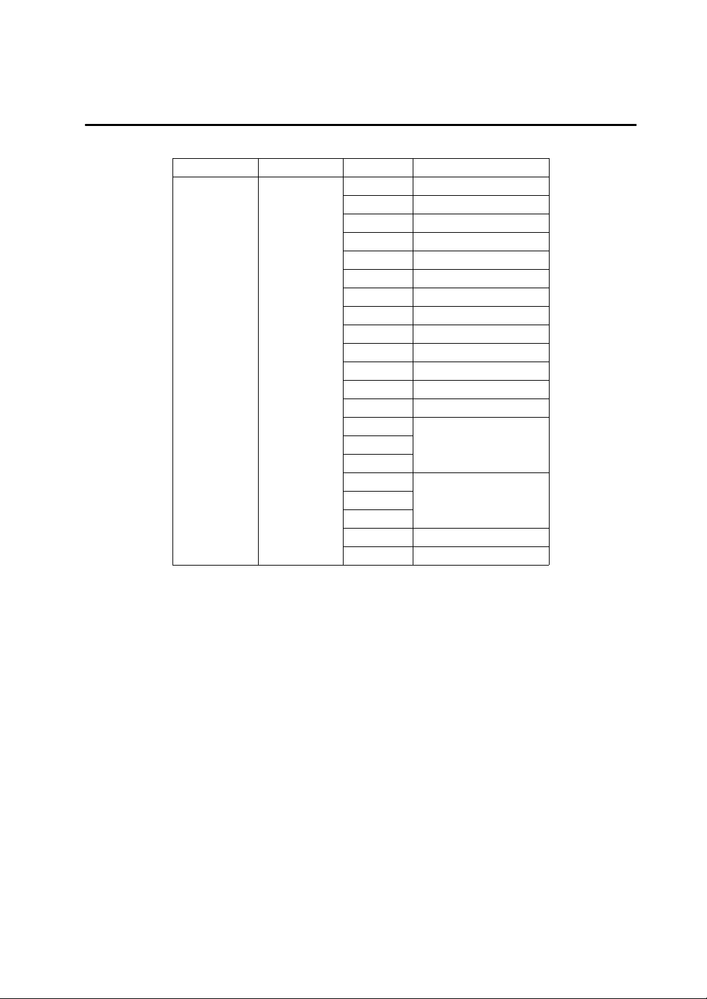
Manual Name Contents Reference No.
V8 Series Reference
Manual
V Series Macro Reference An overview of macros as well as macro editor operations and
V8 Series Introductory
Manual
V8 Series Operation
Manual (this manual)
V8 Series Reference:
Additional Functions
V8 Series Hardware
Specifications
V806 Series Hardware
Specifications
V815 Hardware
Specifications
V808CH Hardware
Specifications
V8 Series Connection
Manual
V Series DLL Function
Specifications
The functions and instructions of the V8 series are explained. 1055NEx
1056NEx
macro command descriptions are explained in detail.
The basic operating procedure of V-SFT version 5 is explained
in detail.
The information related to the operations of V-SFT version 5,
such as software composition, editing procedure or limitations,
is explained in detail.
The additional functions of the MONITOUCH V8 series for the
V-SFT version 5.1.0.0 and later are explained.
Notes on usage and hardware specifications for the V8 series
are explained.
Notes on usage and hardware specifications for the V806
series are explained.
Notes on usage and hardware specifications for the V815 are
described.
Notes on usage and hardware specifications for the V808CH
are described.
The connection and communication parameters for the V8
series and controllers are explained in detail.
An overview and contents of DLL files used for Ethernet
(HKEtn20.DLL) and CF card (VCFAcs.DLL) are explained in
detail.
1057NEx
1058NEx
1060NEx
2016NEx
2017NEx
2018NEx
2019NEx
2201NEx
1059NEx
V8 Series Models
The following MONITOUCH V8 series models are available:
Generic Name Series Model V Series Classification
V815iX V8i or V8i series
V812iS V8i or V8i series
V812S V8
V810iS V8i or V8i series
V810S V8
V810iT V8i or V8i series
V810T V8
V810iC V8i or V8i series
V810C V8
V808iS V8i or V8i series
V series V8 series
V808S V8
V808iC V8i or V8i series
V808C V8
V806iT
V806iM
V806T
V806M
V808iCH
V808CH
V8i or V806i seriesV806iC
V8 or V806 seriesV806C
Please note that the V8 series model names are used as listed above in the manuals.
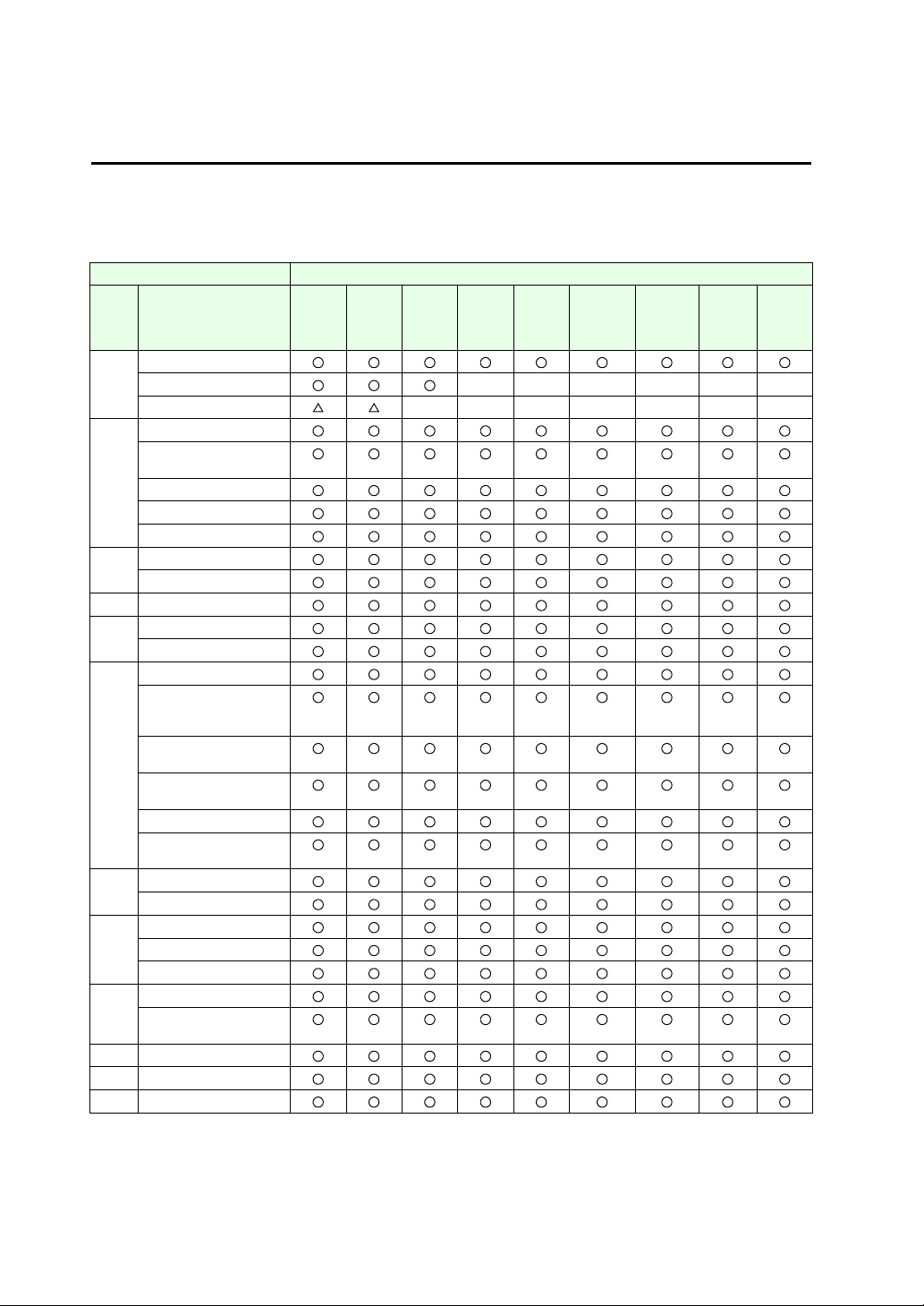
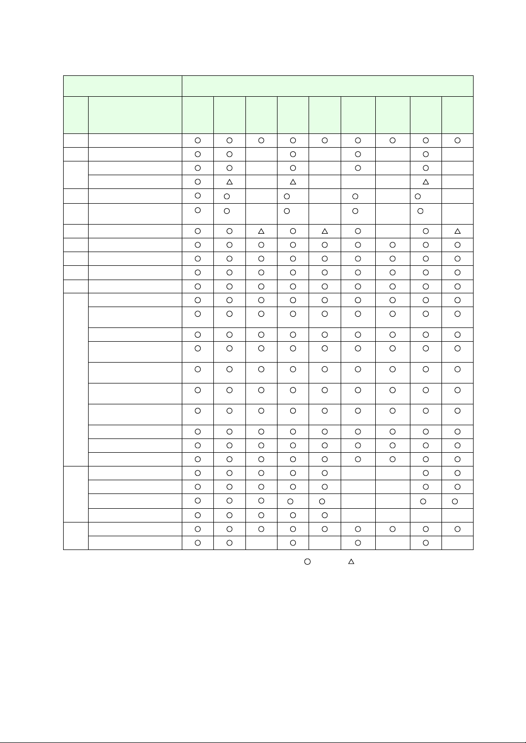
V8 Series Functions
The V8 series is equipped with the following functions. Depending on the V series model, some functions may not
be available. Please keep this limitation in mind. For more information, refer to the related chapter.
V8 Series
V8 Series Reference Manual V8 Series
Chapter Content V815iX V812iS
2Overlap
Superimpose ×× × × ××
Video overlap ×××× ×××
3 Switch
Coordinate output
(for analog only)
Transparency
Multi-output
Delay/Message box
4Lamp
Transparency
5 Data display
6 Message display
Comment display
7 Entry mode
Automatic writing
when the entry target
has been moved
[Function: Cancel]
switch
[Function: Max./Min.
Value Entry] switch
Password: variable
Digital switch
(add/subtract switch)
8 Graph
Scale: variable
9 Trend graph
XY parameters
X scale
10 Sampling
Acknowledge display
function
11 Graphic
12 Time display/calendar
13 Recipe mode
V810iS
V810iT
V808iS
V812S
V810S
V810T
V808S
V810iC
V808iC
V810C
V808C
V808iCH V808CH V806iT
V806iC
V806iM
V806T
V806C
V806M
V8 Series Reference Manual V8 Series
Chapter Content V815iX V812iS
V810iS
V810iT
V808iS
V812S
V810S
V810T
V808S
V810iC
V808iC
V810C
V808C
V808iCH V808CH V806iT
V806iC
V806iM
V806T
V806C
V806M
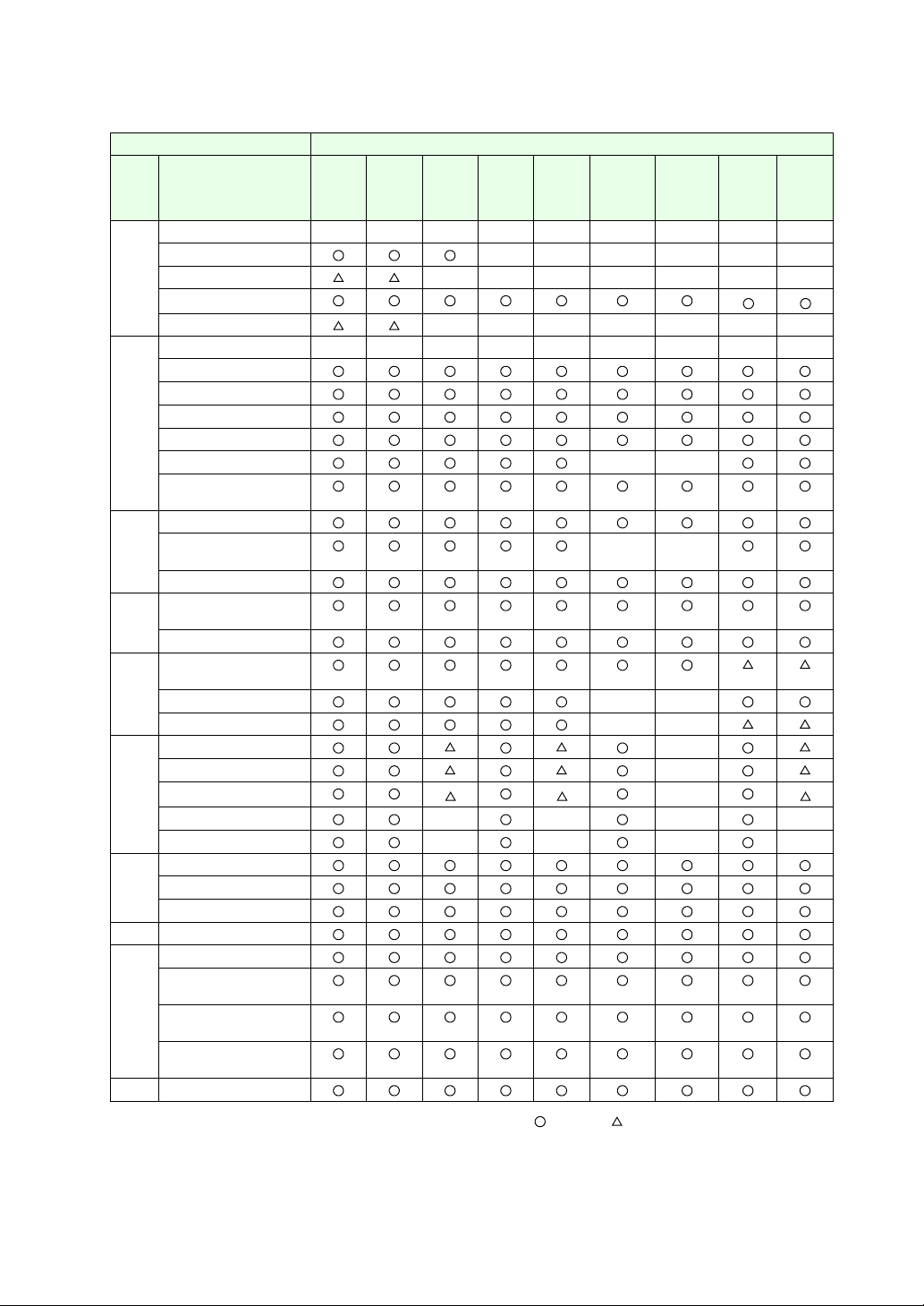
14 Multimedia −−−−− − − −−
Animation ×× × × ××
Video/RGB display ×××× ×××
JPEG display
*1
Sound replay function ×××× ×××
15 Others −−−−− − − −−
Data block area
Memory card mode
CF card
SRAM
CREC ××
Memo pad
(for analog only)
16 Print
Data sheet print
××
Serial
USB
17 Barcode
One-dimensional
Two-dimensional
18 CF card
Built-in
USB ××
2-drive connection ××
19 Ethernet function ×
Screen data transfer ×
PLC connection
*2
*2
×
E-mail ×× × ×
Web server ×× × ×
A1 Buffering area
Store target: SRAM
Store target: CF card
A2 SRAM/clock setting
A3 Display language
Multi-language
selection
Displayed character
selection
Multi-language
screen
− Windows fonts
*1
*2
*1 Not supported by V806iM and V806M
*2 Available only for UDP/IP.
: Available : Optionally available ×: Not available
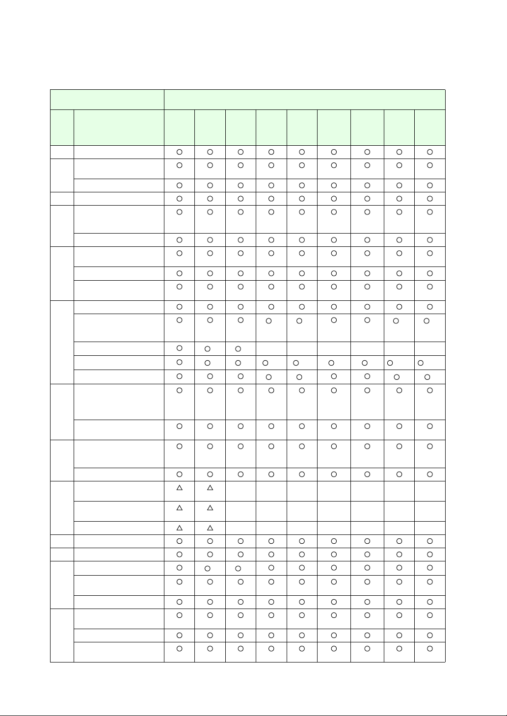
Functions Described in the V8 Series Reference: Additional Functions
Reference: Additional Functions
V8 Series
Chap. Contents V815iX V812iS
V810iS
V810iT
V808iS
2 Global overlap
3 Switch
Multi-function
Continuous buzzer
4 Word lamp
5 Data display
Offset value designation
memory
Attribute change
6 Data display with entry
function
Slider switch
Numerical data entry
(extended)
7 Graph (real values)
Panel meter function
extended
Alarm 2
Indicator setting extended
Scale setting extended
*1 *1
*1 *1 *1 *3 *1 *3 *1 *1 *1 *2 *3 *1 *2 *3
Numerical data display
8 Trend graph
real values
Sampling Buffer Word
No. extended
Trend sampling
Graph show/hide function
9 Alarm function
Parameter addition
function
Acknowledge
10 RGB display
(touch switch emulation)
Enlarged display
(full screen)
Size adjustment ××× × × ××
11 Scroll
12 Expanded data sheet
13 Stroke fonts
Extended point size range
for Windows fonts
*1 *1
16-language selection
14 CF card
Screen added
Message storage
Addition of titles to CSV
file (sampling data)
V812S
V810S
V810T
V808S
V810iC
V808iC
××× × × ××
××× × × ××
V8 Series
V810C
V808iCH V808CH V806iT
V808C
*3 *3 *3 *3
×× × × ××
*3 *3 *3 *3
V806iC
V806iM
V806T
V806C
V806M
V8 Series
V8 Series
Reference: Additional Functions
Chap. Contents V815iX V812iS
V810iS
V810iT
V808iS
V812S
V810S
V810T
V808S
V810iC
V808iC
V810C
V808iCH V808CH V806iT
V808C
V806iC
V806iM
V806T
V806C
V806M
15 Item display function
16 FTP server ×× × ×
17 E-mail certification ×× × ×
Two Ethernet ports ×××× ×
18 Network camera
19 Remote desktop window
display (for analog only)
*1
*1
*1 *3
×
*1 *3
×
×
×
*1
*1
*1*2*3
×
×
*1*2
×
×
20 MES interface ×
21 Operation log/Log viewer
22 Security
23 Macros
24 Tag editing
25 Jump to the target screen
Refined search filter for
project list-view window
Memory batch change
Selection order batch
change
Cross-reference
Macro command search
Text search and
replacement
Image file 3D part
conversion
Text comparison
Selective transfer
Message/comment transfer
26 USB barcode reader ××
USB keyboard ××
USB mouse
*3 *3
××
*3 *3
USB-FDD ××××
27 Ladder transfer USB
Ethernet ×× × ×
*1 The 128-color mode is not supported.
*2 The V806M is not supported.
*3 Not available on the portrait-orientated V808C/V806
: Available : Optionally available ×: Not available

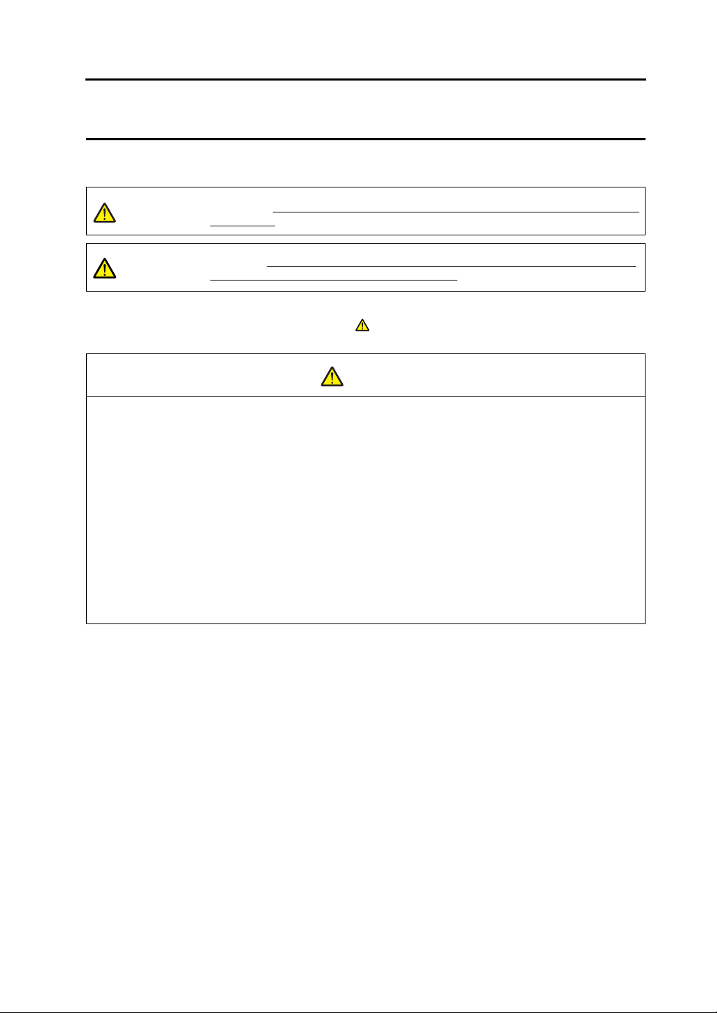
Notes on Safe Usage of MONITOUCH
In this manual, you will find various notes categorized under the following levels with the signal words “DANGER,”
and “CAUTION.”
DANGER
CAUTION
Note that there is a possibility that the item listed with may have serious ramifications.
Indicates an imminently hazardous situation which, if not avoided, will result in death or
serious injury.
Indicates a potentially hazardous situation which, if not avoided, may result in minor or
moderate injury and could cause property damage.
CAUTION
DANGER
• Never use the input function of MONITOUCH for operations that may threaten human life or damage the
system, such as switches to be used in case of emergency. Please design the system so that it can cope
with the malfunction of a touch switch. A malfunction of the touch switch will result in machine accident or
damage.
• Turn off the power supply when you set up the unit, connect new cables, or perform maintenance or
inspections. Failure to do so could cause electric shock or damage to the unit.
• Never touch any terminals while the power is on. Otherwise, electric shock may occur.
• Y ou must put a cover on the terminals on the unit when you turn the power on and operate the unit. Without
the terminal cover in place, electric shock may occur.
• The liquid crystal in the LCD panel is a hazardous substance. If the LCD panel is damaged, do not ingest
the leaked liquid crystal. If the liquid crystal spills on skin or clothing, use soap and wash off thoroughly.
• For MONITOUCH using a lithium battery, never disassemble, recharge, deform by pressure, short-circuit,
reverse the polarity (+/−) of the battery, or dispose of the battery in fire. Failure to follow these conditions will
lead to explosion or fire.
• For MONITOUCH using a lithium battery, never use a battery that is deformed, leaks, or shows any other
signs of abnormality. Failure to follow these conditions will lead to explosion or fire.

CAUTION
• Check the appearance of MONITOUCH when it is unpacked. Do not use the unit if any damage or
deformation is found. Failure to do so may lead to fire, damage, or malfunction.
• For use in a facility or for a system related to nuclear energy, aerospace, medical, traffic equipment, or
mobile installations, please consult your local distributor.
• Operate (or store) MONITOUCH under the conditions indicated in this manual and related manuals. Failure
to do so could cause fire, malfunction, physical damage or deterioration.
• Understand the following environmental limits for use and storage of MONITOUCH. Otherwise, fire or
damage to the unit may result.
- Avoid locations where there is a possibility that water, corrosive gas, flammable gas, solvents, grinding
fluids or cutting oil can come into contact with the unit.
- Avoid high temperature, high humidity, and outside weather conditions, such as wind, rain or direct
sunlight.
- Avoid locations where excessive dust, salt, and metallic particles are present.
- Avoid installing the unit in a location where vibration or physical shock may be transmitted.
• Equipment must be correctly mounted so that the main terminal of MONITOUCH can not be touched
inadvertently. Otherwise, an accident or electric shock may occur.
• Tighten the fixtures of MONITOUCH with a torque in the specified range. Excessive tightening may distort
the panel surface. Loose tightening may cause MONITOUCH to come off, malfunction, or be short-circuited.
• Check periodically that terminal screws on the power supply terminal block and fixtures are firmly tightened.
Loosened screws may result in fire or malfunction.
• Tighten terminal screws on the power supply terminal block equally to a torque of 0.5 N•m. Improper
tightening of screws may result in fire, malfunction, or other trouble.
• MONITOUCH has a glass screen. Do not drop or give physical shock to the unit. Otherwise, the screen
may be damaged.
• Connect the cables correctly to the terminals of MONITOUCH in accordance with the specified voltage and
wattage. Over-voltage, over-wattage, or incorrect cable connection could cause fire, malfunction or damage
to the unit.
• Be sure to establish a ground of MONITOUCH. The FG terminal must be used exclusively for the unit with
the level of grounding resistance less than 100Ω. Otherwise, electric shock or fire may occur.
• Prevent any conductive particles from entering the MONITOUCH. Failure to do so may lead to fire, damage,
or malfunction.
• After wiring is finished, remove the paper used as a dust cover before starting to operate MONITOUCH.
Operation with the cover attached may result in accident, fire, malfunction, or other trouble.
• Do not attempt to repair MONITOUCH at your site. Ask Hakko or the designated contractor for repair.
• Do not disassemble or modify MONITOUCH. Otherwise, malfunctions may occur.
• Hakko Electronics Co., Ltd. is not responsible for any damages resulting from repair, overhaul or
modification of MONITOUCH that was performed by an unauthorized person.
• Do not use a sharp-pointed tool when pressing a touch switch. Doing so may damage the screen.
• Only experts are authorized to set up the unit, connect the cables, or perform maintenance and inspections.
• For MONITOUCH using a lithium battery, handle the battery with care. The combustible materials such as
lithium or organic solvent contained in the battery may generate heat, explode, or catch fire, resulting in
personal injury or fire. Read related manuals carefully and handle the lithium battery correctly as instructed.
• When using a MONITOUCH that has an analog switch resolution with resistance film, do not press two or
more points on the screen at the same time. If two or more positions are pressed at the same time, the
switch located between the pressed positions will activate.
• Take safety precautions during such operations as setting change during running, forced output, start, and
stop. Any misoperation may cause unexpected machine motions, resulting in machine accident or damage.
• In facilities where a failure of MONITOUCH could lead to accident threatening human life or other serious
damage, be sure that the facilities are equipped with adequate safeguards.
• At the time of disposal, MONITOUCH must be treated as industrial waste.
• Before touching MONITOUCH, discharge static electricity from your body by touching grounded metal.
Excessive static electricity may cause malfunction or other trouble.

[General Notes]
• Never bundle control cables and input/output cables with high-voltage and large-current carrying cables such
as power supply cables. Keep these cables at least 200 mm away from high-voltage and large-current
carrying cables. Otherwise, malfunction may occur due to noise.
• When using MONITOUCH in an environment where a source of high-frequency noise is present, it is
recommended that the FG shielded cable (communication cable) be grounded at its ends. However, the cable
may be grounded only at one end if necessary due to unstable communication conditions, or for any other
reason.
• Plug connectors or sockets of MONITOUCH in their correct orientation. Otherwise, malfunctions may occur.
• Do not use thinners for cleaning because they may discolor the MONITOUCH surface. Use an alcohol-based
cleaner which is commercially available.
• If a “data receive error” occurs when MONITOUCH and the counterpart (PLC, temperature controller, etc.) are
started at the same time, read the manual for the counterpart unit and handle the error correctly.
• Avoid discharging static electricity on the mounting panel of MONITOUCH. Static charges can damage the
unit and cause malfunctions. Otherwise, malfunction may occur due to noise.
• Avoid prolonged display of any fixed pattern. Due to the characteristics of the liquid crystal display, an
afterimage may occur. If a prolonged display of a fixed pattern is expected, use the auto OFF function of the
backlight.


1 Introduction
1.1 Installation
Before Installing V-SFT............ .. ... .. ... .................................................. ... ............................1-1
Operating Environment..............................................................................................................1-1
Copyright ...................................................................................................................................1-1
Notes on Usage........................ .......................................... .......................................... ... ..........1-1
Installation........................................................................................................................... 1-2
Installation Procedure................................................................................................................1-2
1.2 Uninstallation
Uninstalling from Start Menu........................... ... .. ...............................................................1-6
Uninstalling from Control Panel...........................................................................................1-8
1.3 Starting
Opening a New File................................................ .. .........................................................1-10
Opening an Existing File............................................................................................ .......1-13
Saving the File ........... ... ... .. ...............................................................................................1-16
Save.........................................................................................................................................1-16
Save As...................................................................................................................................1-17
Closing the File .......... ... ....................................................................................................1-18
1.4 Quitting
2 Editor Configuration
2.1 Names of Components
2.2 Menu Bar
[File] Menu ..........................................................................................................................2-3
[Property] Dialog........................................................................................................................2-4
[Edit] Menu..........................................................................................................................2-7
[View] Menu ........................................................................................................................2-7
[Parts] Menu.......................................... .. ... ... ......................................................................2-7
[Registration Item] Menu....... ... .. ............................................... ... ... .. ..................................2-8
[Screen Setting] Menu........... ... .. ... .................................................. .. ..................................2-8
[System Setting] Menu........................................................................................................ 2-8
[Tool] Menu. .. ... ...................................................................................................................2-9
[Window] Menu ...................................................................................................................2-9
[Help] Menu.......................................................................................................................2-10
2.3 Menu Item [View]
Display Method .......... .......................................................................................................2-11
Item Dialog...............................................................................................................................2-11
How to Move....... .. ... .. .................................................. ... ... .. .............................................2-12
Item Dialog...............................................................................................................................2-13
How to Inset........ .. .................................................. ... .. ... ..................................................2-14
Item Dialog...............................................................................................................................2-15
Floating....................................................................................................................................2-15
Changing the Size of the List-view Window.............................................................................2-16
Content s

2.4 Types of [View]
2.5 Toolbar
Display Method ............................... ... ............................................................................... 2-19
How to Move........................... ... ... .. ... .................................................. .. ... ... .....................2-20
How to Inset............................ ... ... .. .................................................. ... .. ... ........................2-21
Names and Contents of Tools ..........................................................................................2-22
Standard..................................................................................................................................2-22
Draw........................................................................................................................................2-23
Drawing Method......................................................................................................................2-24
Edit..........................................................................................................................................2-25
Layout .....................................................................................................................................2-26
Parts........................................................................................................................................2-27
Parts Mini................................................................................................................................2-28
Pattern.....................................................................................................................................2-28
Multi-language.........................................................................................................................2-29
Font.........................................................................................................................................2-29
Overlap....................................................................................................................................2-30
Component Parts Editing........................................................................................................2-30
2.6 Screen Composition
Screen Outline ..................................................................................................................2-31
What Is an ID? ........................................................................................................................2-33
ID Number Check....................................................................................................................2-35
Screen Structure............................................................................................................... 2-36
Screen Resolution................................................................................................................... 2-36
Screen Capacity......................................................................................................................2-37
Auto Adjustment for Screen Resolution..................................................................................2-37
Screen Setting ..................................................................................................................2-39
[Main] Tab Window .................................................................................................................2-39
[Entry] Tab Window.................................................................................................................2-39
[Others] Tab Window.................................................................. .... ... .....................................2-40
[PLC Memory Transfer] Tab Window......................................................................................2-41
3 Screen Editing
3.1 Editing Procedure
3.2 Setting Up Editing Environment
Background Color Setting................................................................................................... 3-2
Grid Setting......................................................................................................................... 3-3
What Is “Grid”?..........................................................................................................................3-3
Grid Setting...............................................................................................................................3-4
Display Environment Setting.............................. ................................................. ................3-7
[Display] Tab Window...............................................................................................................3-7
[Others] Tab Window.................................................................. .... ... .......................................3-9
3.3 Basic Operation
Calling a Screen................................................................................................................3-12
From the [View] Menu.............................................................................................................3-12
From the Screen List...............................................................................................................3-12
From Project View...................................................................................................................3-14
Copying a Screen .............................................................................................................3-16
From the Screen List...............................................................................................................3-16
Changing Screen Number................................................................................................3-19
Deleting a Screen .............................................................................................................3-22
From the [Edit] Menu...............................................................................................................3-22
From the Screen List...............................................................................................................3-23

3.4 Setting Menu
Menu Types ............... ... .................................................. ..................................................3-25
Pull-down Type........................................................ .... .......................................... ..................3-25
Option Button...........................................................................................................................3-25
Numerical Data Entry Box Type..............................................................................................3-26
Check Box ...............................................................................................................................3-26
List Type..................................................................................................................................3-27
Command Button.....................................................................................................................3-27
Underlined Type for Numerical Data Entry..............................................................................3-28
Underlined Type for Selection.................................................................................................3-28
Memory Setting.................................................................................................................3-29
Display Type for Memory Setting.............................................................................................3-29
Memory Types.........................................................................................................................3-32
3.5 Color Types and Settings
Color Type Setting ............................................................................................................3-35
Color Types.......................................................................................................................3-35
64k-color Type ..................................................................................................................3-36
[Custom Color] Dialog..............................................................................................................3-37
32k-color Type ..................................................................................................................3-39
[Custom Color] Dialog..............................................................................................................3-39
128-color Type ..................................................................................................................3-40
[Custom Color] Dialog for 128-color Type ...............................................................................3-41
Monochrome 16 Gray Scales............................................................................................ 3-42
Monochrome-Type Colors.......................................................................................................3-42
Blinking Setting .................................................................................................................3-43
Blinking Setting Procedure.................................................... .... .......................................... ....3-43
Blinking Time Setting........................................................................... ....................................3-44
3.6 Parts
Parts Types and Limitation................................................................................................3-45
Types of Parts..................................... .......................................... .... .......................................3-45
Capacity for Parts Placement..................................................................................................3-47
Placing Parts.....................................................................................................................3-49
From the Parts List..................................................................................................................3-49
From the [Parts] Menu.............................................................................................................3-51
From the Parts Toolbar............................................................................................................3-52
From Catalog View..................................................................................................................3-53
How to Modify the Placed Part................................ ... .. .....................................................3-55
For Single Part.........................................................................................................................3-55
For Linked Part........................................................................................................................3-61
3.7 Parts Placement and Setting
Overlap..............................................................................................................................3-65
Normal Overlap Display...........................................................................................................3-65
Multi-overlap (Call-overlap) Display.........................................................................................3-72
Switch / Lamp................... .. ... ... .........................................................................................3-73
Data Display............................................ ... ... .. .................................................. ... .............3-74
Numerical Data Display / Character Display / Message Display.............................................3-74
Table Data Display..................................................................................................................3-75
Message Display / Comment Display...............................................................................3-80
Entry Mode........................................................................................................................3-81
Graph................................................................................................................................3-84
Trend Graph / Trend Sampling......................................................................................... 3-85
Data Sampling............ ... ... .. ...............................................................................................3-86
Alarm Tracking / Bit Order (Time Order) Alarming / Alarm Sub Display / Alarm Logging.3-87
Graphic / Graphic Relay........................................................................ ............................3-88
Macro / Interval Timer.................................................................................. .. ...................3-89
Time Display / Calendar....................................................................................................3-90

Recipe............................................................................................................................... 3-91
Animation / Sound.............................................................................................................3-92
Video Display / JPEG Display...........................................................................................3-93
Data Block Area / Memory Card / Memo Pad................................ ... ... ............................. 3-94
3.8 Useful Functions for Screen Editing
[Edit] Menu........................................................................................................................ 3-95
Right-click Menu (with No Item Selected)......................................................................... 3-96
Right-click Menu (with an Item Selected )............................................. .. ... ... ..................... 3-97
Paste to the Selected Screen .... ... .. .................................................. ... ............................. 3-98
Multi Copy....................... .................................................................................................. 3-99
Setting Example....................................................................................................................3-101
Alignment (E.g. Flush Left) .......................................... ... ................................................ 3 -1 02
Arrangement (Equal) (E.g. Vertically).............................................................................3-104
Put All in Same Size .......................................................................................................3-105
Changing Part.................................................................................................................3-106
Link / Link Cancel........................................................................................................ ... ....... 3-106
Change to Switch / Change to Lamp ...................................................................... .... ... .......3-106
Modify Part............................................................................................................................3-108
Batch Change................................. ... ............................................................................. 3-109
Setting Method......................................................................................................................3-109
Detail Setting.............. ... .. ... ............................................................................................. 3-111
Setting Method......................................................................................................................3-111
Selection Environment Setting........................................................................................ 3-112
Setting Method......................................................................................................................3-112
4Drawing
4.1 Drawing Toolbar
Display Method ............................... ... ................................................................................. 4-1
Icons ...................................................................................................................................4-2
4.2 Attribute Setting Icon
Selecting Colors..................................................................................................................4-5
Selecting Arrow Type.......................................................................................................... 4-7
Selecting Line Style ............................................................................................................4-7
Limitations on Line Styles.........................................................................................................4-7
4.3 Drawing Methods
Line..................................................................................................................................... 4-8
Single Line ........................................................................ .......................................... ..............4-8
Continuous Line........................................................................................................................4-9
Box.................................................................................................................................... 4-10
Rectangle................................................................................................................................4-10
Parallelogram..........................................................................................................................4-14
Polygon...................................................................................................................................4-15
Round Chamfering / Chamfering............................................................................................4-18
Circle................................................................................................................................. 4-19
Circle.......................................................................................................................................4-19
Arc and Sector........................................................................................................................4-21
Ellipse......................................................................................................................................4-24
Elliptical Arc and Elliptical Sector..................................................................... .......................4-26
Text................................................................................................................................... 4-31
How to Enter or Place Text and Multi-text...............................................................................4-31
[Text] Dialog............................................................................................................................4-32
[Multi Text] Dialog................................................................................................................... 4-36
Dot ....................................................................................................................................4-38
Drawing Method......................................................................................................................4-38

Paint.................................................................................................................................. 4-39
Paint Command Usage............................................................................................................4-39
How to Check the Painted Area...............................................................................................4-40
Paint Properties.................................................................................................................4-41
Scale.................................................................................................................................4-42
Bar Graph Scale......................................................................................................................4-42
Pie Graph Scale.......................................................................................................................4-43
Trend Graph Scale................................................................ .......................................... ........4-46
Pattern...............................................................................................................................4-48
Placing Patterns.......................................................................................................................4-48
Placing Multiple Patterns Continuously ...................................................................................4-49
Graphic Call ......................... .............................................................................................4-51
Placing Graphics......................................................................................................................4-51
Screen Library...................................................................................................................4-53
Placing Screen Library.............................................................................................................4-53
[Screen Library] Dialog............................................................................................................4-55
4.4 Graphic Properties Setting
How to Display the Item Dialog................................................................................................4-58
Example of Item Dialog............................................................................................................4-59
5 Registration Items
5.1 Outline of Registration Items
5.2 Contents of Registration Items
5.3 Screen
Calling a Screen..................................................................................................................5-3
Screen Editing.....................................................................................................................5-3
5.4 Message
Message Structure..............................................................................................................5-4
Relationship between Group Numbers and Absolute Addresses..............................................5-5
Calling a Message...............................................................................................................5-6
Message Editing..................................................................................................................5-7
Copying and Pasting Messages.............................. .......................................... .... ....................5-7
Deleting Messages........................................... .......................................... .... ... ........................5-8
Message Search and Replacement...........................................................................................5-9
Message Display Environment Setting.............................................................................5-10
Mark.........................................................................................................................................5-11
5.5 Macro Block
Macro Block Structure.......................................................................................................5-12
Calling a Macro Block .......................................................................................................5-12
Macro Block Editing ..........................................................................................................5-12
5.6 Graphic Library
Graphic Library Structure.............................................................................. ....................5-13
Calling the Graphic Library................................................................................................5-13
Graphic Library Editing................................. .....................................................................5-14
Offset Position Setting............................... .... ... .......................................... .............................5-14
Parameter Setting....................................................................................................................5-15
Data Display............................................................................................................................5-22
Graphic Library Environment Setting................................................................................5-24
Base Screen Dsp. ([Others] Tab Window)...............................................................................5-24
Background ([Others] Tab Window)........................................................................................5-25

5.7 Overlap Library
Overlap Library Structure.................................................................................................. 5-26
Calling an Overlap Library................................................................................................ 5-26
Editing an Overlap Library ........................................ ... ... .. ................................................ 5-27
Placing an Overlap Display Part.............................................................................................5-27
Item Placement on Overlap Display ........................................................................................5-28
Other Settings.................... ... .. ... .................................................. .. ................................... 5-29
Base Screen Display...............................................................................................................5-29
Macro Setting..........................................................................................................................5-30
5.8 Screen Library
Outline of Screen Library..................................................................................................5-31
Saving of Screen Memory.......................................................................................................5-31
Screen Parts Management Through Screen Library...............................................................5-32
Screen Library Structure................................................................................................... 5-32
Calling a Screen Library........ .. ... ... .. .................................................. ... ............................. 5-33
Screen Library Editing.......................................................................................................5-33
Notes on Editing................................................................ ... .......................................... ......... 5-33
Offset Position Setting..................................................................... ........................................5-34
Placing a Screen Library................................................................................................... 5-34
5.9 Data Block
Data Block Structure..................... .. ... .. ... .................................................. ... .. ...................5-35
Calling a Data Block.......................................................................................................... 5-35
Data Block Editing.............. ... .. ... ... .. .................................................. ... .. ... ........................5-36
Parts........................................................................................................................................5-36
Drawing...................................................................................................................................5-36
Data Block Environment Setting.......................................................................................5-37
Base Screen Dsp. ([Others] Tab Window).............................................................................5-37
Background ([Others] Tab Window)........................................................................................5-38
5.10 Pattern
Pattern Structure...............................................................................................................5-39
Calling a Pattern ...............................................................................................................5-39
Pattern Editing ..................................................................................................................5-40
[Pen] Icon................................................................................................................................5-40
[Eraser] Icon............................................................... ... .......................................... .... ............5-41
[Straight Line] Icon.......................................... .......................................... .... ..........................5-41
[Rectangle] Icon......................................................................................................................5-42
[Circle] Icon.............................................................................................................................5-42
[Text] Icon ...............................................................................................................................5-43
[Paint] Icon......................................................................................... .... .................................5-45
[Box Select Area] Icon............................................................................................................. 5-45
Transforming Patterns .. .. .................................................................................................. 5-47
Image File Import and Storage.........................................................................................5-50
Importing an Image File..........................................................................................................5-50
Storing in an Image File..........................................................................................................5-53
Pattern Environment Setting............................................................................................. 5-53
Display Environment...............................................................................................................5-54
Background Color Setting.......................................................................................................5-54
Placing a Pattern...............................................................................................................5-55
5.11 Data Sheet
Data Sheet Structure ......... ... .. .................................................. ... ..................................... 5-56
Calling a Data Sheet......................................................................................................... 5-56
Data Sheet Editing.................. ... ... ................................................. ... ................................ 5-57
Data Sheet Setting..................................................................................................................5-57
Drawing...................................................................................................................................5-58

Data Sheet Environment Setting............................. ... .. ... ... ............................................... 5-59
Display Environment................................................................................................................5-59
Grid Setting..............................................................................................................................5-60
5.12 Page Block
Page Block Structure ........................................................................................................ 5-61
Calling a Page Block.................. ... .. ..................................................................................5-61
Page Block Editing............................................................................................................ 5-62
5.13 Direct Block
Direct Block Structure ....................................................................................................... 5-64
Calling a Direct Block.................... .................................................. .. ................................5-64
Direct Block Editing...........................................................................................................5-65
5.14 Screen Block
Screen Block Structure .....................................................................................................5-67
Calling a Screen Block.................. .. ... ... .. .................................................. ........................5-67
Screen Block Editing......................................................................................................... 5-68
5.15 Tile
Tile Structure........................................................................................... ..........................5-69
Calling a Tile .....................................................................................................................5-69
Tile Editing ............ ... .. ... ... .................................................................................................5-70
5.16 Animation
Animation Function Structure............................................................................................5-72
Calling an Animation Function.......................................................................................... 5-72
Animation Editing ..............................................................................................................5-73
Frame Editing........................................ .. ... ... ............................................... .. ... ... .............5-75
Frame Structure.......................................................................................................................5-75
Frame Editing..........................................................................................................................5-75
5.17 Comment
Comment Structure........................................................................................................... 5-76
Limitations on Comments........................................................................................................5-76
Calling a Comment............................................................................................................5-77
Comment Editing...............................................................................................................5-77
Entering a Comment....................................................... .... .......................................... ... ........5-77
Text Properties........................................................................................................................5-78
Deleting a Comment.................... .......................................... .......................................... .... ....5-79
Comment Import and Export....................................................................................................5-80
[Page] Menu......................................................................................................................5-83
5.18 Multi-language
6 Transfer with V8
6.1 Transfer Methods
List of Transfer Methods.....................................................................................................6-1
Using a Communication Cable..................................................... ... ....................................6-1
V-CP (Serial Port)......................................................................................................................6-1
Ethernet (LAN Port)....................................... .......................................... ... ...............................6-2
USB (USB-B Port).....................................................................................................................6-2
Using a Card....... .. .................................................. ... .................................................. .. ..... 6-3
CF Card.....................................................................................................................................6-3
Memory Card.............................................................................................................................6-3
Using a Modem...................................................................................................................6-4
6.2 Type of Transferred Data
Transfer Data List............. .. ... .................................................. ............................................6-5
System Program File.................................................................................................................6-6

6.3 Preliminaries
Preparation for MONITOUCH...................................................... .. ..................................... 6-7
New MONITOUCH....................................................................................................................6-7
Existing MONITOUCH .................................... .... .......................................... ... .... .....................6-8
Preparation for Peripheral Equipment.................................................................................6-9
6.4 Transfer Procedure (Using a Communication Cable)
V-CP .................................................................................................................................6-10
System Configuration..............................................................................................................6-10
Transfer Procedure from the Editor to MONITOUCH .............................................................6-10
Transfer Procedure from the Editor to MONITOUCH .............................................................6-14
Data Comparison between Editor and MONITOUCH.............................................................6-16
Ethernet ............................................................................................................................6-19
System Configuration..............................................................................................................6-19
Transfer Procedure from the Editor to MONITOUCH .............................................................6-19
Transfer Procedure from the Editor to MONITOUCH .............................................................6-24
Data Comparison between Editor and MONITOUCH.............................................................6-27
USB...................................................................................................................................6-29
System Configuration..............................................................................................................6-29
Before Transfer via USB.........................................................................................................6-29
Transfer Procedure from the Editor to MONITOUCH .............................................................6-33
6.5 Transfer Procedure (Using a Card)
CF Card ............................................................................................................................6-36
System Configuration..............................................................................................................6-36
Transfer Procedure from the CF card to MONITOUCH..........................................................6-36
Memory Card.................................................................................................................... 6-43
System Configuration..............................................................................................................6-43
Transfer Procedure from Memory Card to MONITOUCH.......................................................6-43
6.6 Transfer Procedure (Using a Modem)
Preliminaries ..................................................................................................................... 6-49
Setting Procedure ............................................................................................................. 6-49
AT Command Setting..............................................................................................................6-50
Setting on the V Series...........................................................................................................6-52
Description of Connections.....................................................................................................6-53
Screen Data Transfer..............................................................................................................6-54
Transfer Error Messages Displayed on V-SFT............................................. ....................6-55
6.7 After Transfer (Communication with PLC)
Connection with PLC........................................................................................................6-56
Preliminaries on MONITOUCH......................................................................................... 6-56
Switching to RUN (= Communicating) Mode...........................................................................6-56
Display Contents after Communication...................................................................................6-57
7Print
7.1 Overview
Available Printers................................................................................................................7-1
Operating Procedure....... ... ... .. ... ... ................................................. ..................................... 7-1
[Option Setting] Dialog........................................................................................................7-2
[Page Setting] Dialog................................................................................................................7-2
Output Range............................................................................................................................7-3
Print Format ..............................................................................................................................7-5
Print Preview........................................ ... ... .........................................................................7-6
Operating Procedure.................................................................................................................7-6
Print Current Window.......................................................................................................... 7-6
Operating Procedure.................................................................................................................7-6

Print Example............................................. .........................................................................7-7
Screen Output............................................................................................................................7-7
List Output.................................................................................................................................7-7
Table Print.................................................................................................................................7-8
System Setting...........................................................................................................................7-9
Memory Use List........................................................................................................................7-9
Use Cross-reference............................... ... .......................................... .... ... .............................7-10
Animation.................................................................................................................................7-11
8 Useful Functions
8.1 Simulator
Overview.............................................................................................................................8-1
Operating Procedure...........................................................................................................8-3
Connecting a Computer and the V8 series.........................................................................8-4
Via V-CP....................................................................................................................................8-4
Via Ethernet...............................................................................................................................8-5
Via USB.....................................................................................................................................8-5
Screen Data and Simulator Program Transfer....................................................................8-6
Screen Data Transfer................................................................................................................8-6
Setting on MONITOUCH ...........................................................................................................8-8
Starting and Quitting ..... ... .. ............................................................................................... 8-11
Starting ....................................................................................................................................8-11
Quitting ....................................................................................................................................8-12
Starting and Stopping Commu ni cat io n............................................ .. ... .............................8-13
Starting Communication..........................................................................................................8-13
Stopping Communication.........................................................................................................8-13
Communication Setting............................................................................................................8-14
Via Ethernet.............................................................................................................................8-15
Via USB...................................................................................................................................8-15
Structure of the [Simulator] Window..................................................................................8-16
Menu Bar.................................................................................................................................8-17
Icon Menu................................................................ .... .......................................... ... ...............8-20
Structure of the Sheet..............................................................................................................8-21
[Untitled] Sheet........................................................................................................................8-23
Memory Addresses Displayed on Simulator............................................................................8-25
Test Example....................................................................................................................8-26
Testing Bit Access Device.......................................................................................................8-26
Testing Word Access Device...................................................................................................8-28
Error List............................................................................................................................ 8-30
8.2 Emulator
Overview...........................................................................................................................8-32
Operating Procedure.........................................................................................................8-33
Starting and Quitting ..... ... .. ............................................................................................... 8-33
Starting ....................................................................................................................................8-33
Quitting ....................................................................................................................................8-34
Operation ..........................................................................................................................8-35
Structure of the [Emulator] Window.................................................................................. 8-36
Menu Bar.................................................................................................................................8-36
Icon Menu................................................................ .... .......................................... ... ...............8-37
8.3 Useful Tools for Creating a Manual
Copying Screen Image to the Clipboard...........................................................................8-38
Operating Procedure...............................................................................................................8-39
Copying an Image Displayed on the Editor .............................................................................8-39
Pasting the Copied Image on another Application Software...................................................8-40
Converting to Rich Text Format........................................................................................8-41
Operating Procedure...............................................................................................................8-41

Emulator............................................................................................................................8-43
Copying an Image Displayed on Emulator..............................................................................8-43
Pasting the Copied Image on another Application Software...................................................8-44
8.4 Item List
Display Method ............................... ... ............................................................................... 8-45
Item List Window...............................................................................................................8-46
Configuration...........................................................................................................................8-46
Icon Menu ...............................................................................................................................8-47
Operation Procedure....... ... ... .. ... ... ................................................. ................................... 8-48
Text Change............................................................................................................................8-48
Memory Change......................................................................................................................8-50
Coordinate Change.................................................................................................................8-51
Display of the Item Dialog.......................................................................................................8-52
8.5 List of Memory Address in Use
Operation Procedure....... ... ... .. ... ... ................................................. ................................... 8-53
Searching with Memory Range Designated............................................................................8-53
Searching the Whole File.......................................................................... ..............................8-55
When [Cross-reference] Is Not Checked: ...............................................................................8-56
8.6 Customizing the Toolbar
Overview........................................................................................................................... 8-57
Icon................................................................................................................................... 8-57
How to Add..............................................................................................................................8-57
How to Delete..........................................................................................................................8-59
How to Change Order.............................................................................................................8-60
Separator Line ......... .. ............................................... ... ... .. ... .............................................8-61
What Is “Separator Line”?.......................................................................................................8-61
How to Add..............................................................................................................................8-61
How to Delete..........................................................................................................................8-62
8.7 Other Functions in the [Tool] Menu
[Tool] Menu........................ ... .. .......................................................................................... 8-63
Error Check....................................................................................................................... 8-64
Operating Procedure...............................................................................................................8-64
Reading the Error Check List..................................................................................................8-65
List of Memory Use........................................................................................................... 8-67
Operating Procedure...............................................................................................................8-67
Changing Memory.............................................................................................................8-69
Changing All Memory..............................................................................................................8-69
Changing Memory of Selected Items Only..............................................................................8-71
Windows Font Change All/List/Registrati on............................................. .........................8-72
DXF File Convert .......... .. .................................................................................................. 8-73
Operating Procedure...............................................................................................................8-73
Copy Image to Pattern...................................................................................................... 8-75
Operating Procedure...............................................................................................................8-75
Tag Table . .........................................................................................................................8-77
8.8 File Management
File Management Outline..................................................................................................8-78
File Management Functions............................................................ ... .... .................................8-78
Files for File Management......................................................................... .... ..........................8-78
File Comparison..................................................................................... ........................... 8-79
Operating Procedure...............................................................................................................8-79
[Comparison] Window .............................................................................................................8-80
How to Copy after Comparison...............................................................................................8-82
Copying the File................................................................................................................8-89
Deleting the File................................................................................................................8-90

Dividing and Combining the File.......................................................................................8-91
8.9 Wizard
Overview...........................................................................................................................8-93
Starting Wizard........... ... ... ................................................................................................. 8-93
8.10 Component Parts
Overview...........................................................................................................................8-95
Component Parts Placement ........................ ................................................. ...................8-95
Details of Component Parts..............................................................................................8-96
Appendix 1 Font
Font Types
Font Setting Procedure .....................................................................................................A1-4
Font Size...........................................................................................................................A1-7
Memory Sizes of Fonts .....................................................................................................A1-8
Language Entry Method
English/Western Europe, English/Western Europe HK Gothic ,
and English/Western Europe HK Times............................................................................A1-9
Chinese (Traditional) and Chinese (Simplified)...............................................................A1-12
Korean.............................................................................................................................A1-14
Central Europe/Cyrillic/Greek/Turkish.............................................................................A1-16
HK Gothic and HK Times
Outline.............................................................................................................................A1-18
Points of English/Western Europe HK Gothic/HK Times................................................A1-20
Setting Procedure ...........................................................................................................A1-21
1. Font Type Setting...................................... .. ................................................................A1-22
2. Font Setting for Individual Functio n s...........................................................................A1-23
3. Manual Font Setting...................................... ....................................................... .......A1-25
4. Data Transfer to the V Series......................................................................................A1-27
Error for the V series.......................................................................................................A1-28
Dividing the File....................................................................................... ... .... .........................8-91
Combining the File...................................................................................................................8-92
Start from Catalog View.................................................. .......................................... .... ...........8-93
Start from [Parts] Menu............................................................................................................8-94
Differences between Fonts and Windows Fonts....................................................................A1-2
Distinguishing Fonts on MONITOUCH...................................... .......................................... ...A1-3
Fonts.......................................................................................................................................A1-4
Transfer Font Setting..............................................................................................................A1-6
Enlarge X/Y.............................................................................................................................A1-7
Points......................................................................................................................................A1-7
Using “English/Western Europe” Font on Non-compatible Operating System.......................A1-9
Using “Chinese” Font on Non-compatible Operating System...............................................A1-12
Using “Korean” Font on Non-compatible Operating System................................................A1-14
Using “Central Europe/Cyrillic/Greek/Turkish” Fonts on Non-compatible
Operating System................................................................................................................. A1-16
Display Function Specifications............................................................................................A1-20
Automatic Font Setting.......................................................... .......................................... .... .A1-25
Manual Font Setting..............................................................................................................A1-25
Notes on Font Data to be Transferred..................................................................................A1-27

Windows Font
Limitations.......................................................................................................................A1-29
Option .............................................................................................................................A1-30
Setting Procedure ...........................................................................................................A1-31
In Text Properties Setting......................................................................................................A1-31
In Message Editing....................................... .......................................... ... ............................A1-32
Font Registration...................................................................................................................A1-33
[Windows Font List] Window...........................................................................................A1-35
Location of the Dialog.............................................................. ... ..........................................A1-35
Change All Windows Fonts.............................................................................................A1-36
Procedure..............................................................................................................................A1-36
Windows Fonts for Language Selection......................................................... ................A1-38
Conditions for Language Selection Using Windows Fonts ...................................................A1-38
Multi-Language Editing Using Windows Fo nt s........................................................ ..............A1-38
Windows Font Not Installed on Your Computer Exists in Screen Data..........................A1-39
Appendix 2 3D Parts
64k- or 32k-color Type
Switch / Lamp ............... ....................................................................................................A2-1
Available Parts........................................................................................................................A2-1
Setting Procedure...................................................................................................................A2-3
Flashing Function....................................................................................................................A2-8
Data Display/Graph/Calendar....... .. .................................................. ... .. ... ........................A2-9
Available Parts........................................................................................................................A2-9
Setting Procedure...................................................................................................................A2-9
Customizing....................................................................................................................A2-14
Notes.....................................................................................................................................A2-14
Setting Procedure.................................................................................................................A2-15
128-color Type
Switch / Lamp ............... ..................................................................................................A2-17
Available Parts......................................................................................................................A2-17
Setting Procedure.................................................................................................................A2-19
Notes
Notes on Dealing with 3D Parts......................................................................................A2-24
Memory Size...................................................................................................................A2-24
Limitation on Parts ............................. .............................................................................A2-25
How to Count Patterns..........................................................................................................A2-25
Color Pallets....................................................................................................................A2-26
Appendix 3 Parts Editing
Parts
Structure of a Part........................................... ... ................................................. ... ...........A3-1
Editable Parts....................................................................................................................A3-1
Calling the [Modify Part] Window
Calling...............................................................................................................................A3-2
Closing..............................................................................................................................A3-3
Parts Editing
Overlap .............................................................................................................................A3-4
Structure..................................................................................................................................A3-4
Procedure................................................................................................................................A3-4
Switch / Lamp ............... ....................................................................................................A3-5
Structure..................................................................................................................................A3-5
Procedure................................................................................................................................A3-5

Data Display............................................ ... ... .. .................................................. ... ...........A3-10
Structure...............................................................................................................................A3-10
Procedure............................................................................................................................. A3-10
Keypad............................................................................................................................A3-11
Structure...............................................................................................................................A3-11
Procedure............................................................................................................................. A3-11
Slider Switch/Scroll Bar.............................. ... .. ................................................................A3-11
Structure...............................................................................................................................A3-11
Procedure............................................................................................................................. A3-11
Graph..............................................................................................................................A3-12
Bar Graph.............................................................................................................................A3-12
Pie Graph.............................................................................................................................. A3-13
Closed Area Graph...............................................................................................................A3-17
Panel Meter..........................................................................................................................A3-19
Statistic Bar Graph........................................................................................................ ........A3-20
Statistic Pie Graph............................................................................ ... .................................A3-21
Trend Graph (Trend Sampling).............................................................................................A3-22
Display Area............................................ ........................................................................A3-23
Structure...............................................................................................................................A3-23
Procedure............................................................................................................................. A3-23
Data Sampling............ ... ... .. .............................................................................................A3-24
Structure...............................................................................................................................A3-24
Procedure............................................................................................................................. A3-24
Calendar..........................................................................................................................A3-26
Structure...............................................................................................................................A3-26
Procedure............................................................................................................................. A3-27
After Completion of Parts Editing
Access from [Parts List] ..................................................................................................A3-28


1 Introduction
1.1 Installation
Before Installing V-SFT
Operating Environment
Make sure that your system meets the system requirements given in the following table before starting
the V-SFT Ver. 5.
Computer PC/AT compatible computer for Windows
OS* Windows98 SE/Me/NT Version 4.0/2000/XP/XP64 Edition/
CPU Pentium III processor with 800 MHz or above
Memory 512 MB or above
Hard disk Free disk space before installation: 1 GB or above
CD-ROM drive 24× or above recommended
Display Resolution 1024 × 768 (XGA) or above recommended
Display colors High color (16-bit) or above
Vista (32-bit, 64-bit)/7 (32-bit, 64-bit)
(Pentium IV 2.0 GHz or above recommended)
1.1 Installation
1
Introduction
* In the case of Windows NT Version 4.0/2000/XP/XP64 Edition/Vista (32-bit, 64-bit)/
7 (32-bit, 64-bit), install the V-SFT editor with authorization of administrator.
Copyright
• The software as well as its copyrights or all other rights related to the software is the property of
Hakko Electronics Co., Ltd.
• The software may not be used or copied, in whole or in part, without permission of Hakko
Electronics Co., Ltd.
• The specifications and components of the software are subject to change without prior notification.
• Hakko Electronics Co., Ltd., bears no responsibility for the results of using the software.
• You must purchase one set of software for each computer in principle.
• Windows is the registered trademark of Microsoft Corporation in the United States.
• All other company names or product names are trademarks or registered trademarks of their
respective holders.
Notes on Usage
• The software may not be correctly installed if resident programs such as a virus scanning program
are running. Be sure to close all applications before installing the software.
• For the CD-ROM, the side on which the product name is printed is front and the other side on
which nothing is printed is back.
If the CD-ROM is scratched with a sharp object, it may not be read correctly. The computer reads
backside of the CD-ROM. Touching backside of the CD-ROM and leaving fingerprints will result in
malfunction. Handle both sides of the CD-ROM with care.
• When placing the CD-ROM in the CD-ROM drive, pay attention to the orientation of the disc and
place the disc in the drive as instructed in the instruction manual of your computer.
• If the free space for memory becomes insufficient during running the configuration software,
Windows may forcefully terminate the software.
To prevent data from being deleted due to forced termination, save the screen data file regularly.
1-1

1.1 Installation
Installation
Installation Procedure
Follow the procedure below to install V-SFT.
1. Boot computer with Windows operating system.
2. Place the “V-SFT Ver. 5” CD-ROM in the CD-ROM drive.
The display shown below automatically appears on the screen.
3. Click [INSTALL].
1-2

1.1 Installation
4. The following dialog is displayed: Click the [Next] button.
5. The [License Agreement] dialog is displayed.
Read the contents thoroughly. If you agree to the License Agreement, select [I accept the terms of
the license agreement.] and click the [Next] button.
1
Introduction
6. The [Customer Information] dialog is displayed.
Enter a user name and company name, and click the [Next] button.
1-3

1.1 Installation
7. The [Choose Destination Location] dialog is displayed.
8. The “Ready to Install the Program” dialog is displayed.
If the designated folder is correct, click the [Next] button. To change the folder, click the [Change]
button and select the desired folder. Then click the [Next] button.
The default location of where to install V-SFT depends on the OS in use.
• For Windows XP/2000/98/Me/NT C:\Program Files\V-SFT V5
• For Windows Vista (32-bit, 64-bit)/7 (32-bit, 64-bit) C:\MONITOUCH\V-SFT V5
Click the [Install] button.
1-4

1.1 Installation
9. Installation is automatically started.
To cancel installation, click the [Cancel] button.
10. When installation is completed, the following dialog is displayed.
If you intend to use ladder transfer via USB or Ethernet, click [Yes]. For more information, refer to
the V8 Series Reference: Additional Functions.
If not, click [No].
1
Introduction
11. When installation is completed, the following dialog is displayed.
To read the “ReadMe” file, check [ Read the ReadMe file.].
To start-up the editor immediately, check [ Start up V-SFT Version 5.0 now.].
Installation wizard is closed by pressing the [Finish] button.
The installation has been completed.
1-5

1.2 Uninstallation
1.2 Uninstallation
This section describes the procedure for uninstalling the V-SFT Ver. 5. installed on the hard disk.
Uninstalling from Start Menu
1. Click [Start] → [Programs] → [V-SFT5] → [Uninstall].
2. The following dialog is displayed:
Select [Remove] and click the [Next] button.
1-6
3. The following confirmation dialog is displayed.
Click the [Yes] button.

4. Uninstallation begins.
5. When uninstallation is completed, the following dialog is displayed.
Click the [Finish] button.
1.2 Uninstallation
1
Introduction
The uninstallation has been completed.
1-7

1.2 Uninstallation
Uninstalling from Control Panel
1. Click [Add or Remove Programs] selected from [Control Panel].
1-8
2. The [Add or Remove Programs] dialog is displayed.
Select [V-SFT Version 5.0] and click the [Remove] button.

3. The following confirmation dialog is displayed.
Click the [Yes] button.
4. Uninstallation begins.
1.2 Uninstallation
1
Introduction
5. When uninstallation is completed, the following dialog is displayed.
Click the [Finish] button.
6. The [Add or Remove Programs] dialog is displayed again.
To finish uninstalling the software, click the [OK] button.
The uninstallation has been completed.
1-9

1.3 Starting
1.3 Starting
Opening a New File
Start-up the editor and open a new screen file following the procedure below.
1. Click [Start] → [Programs] → [V-SFTV5] → [V-SFTV5].
2. V-SFT Ver. 5 is started.
1-10

3. Click [New] from the [File] menu or click the [New] icon on the toolbar.
OR
4. The [Edit Model Selection] dialog is displayed.
Select the model name and click [OK].
1.3 Starting
1
Introduction
5. The [PLC1 Connection Device Selection] dialog is displayed.
Select the PLC type and click [OK].
1-11

1.3 Starting
6. The [Device Connection Setting] dialog for the selected device and the [Screen [0] Edit] window of
the new file are cascaded.
7. Make the necessary settings in the [Device Connection Setting] dialog and close the dialog.
Only the [Screen [0] Edit] window is now open. Proceed to screen editing in the window.
For more information on the [Device Connection Setting] dialog, refer to the V8 Series Connection
Manual.
This step completes the procedure for opening a new file.
1-12

Opening an Existing File
Open an existing file following the procedure below.
1. Click [Start] → [Programs] → [V-SFTV5] → [V-SFTV5].
2. V-SFT Ver. 5 is started.
1.3 Starting
1
Introduction
1-13

1.3 Starting
3. Click [Open] from the [File] menu or click the [Open] icon on the toolbar.
OR
4. The [Open] dialog is displayed.
Select a file type from [Files of type], and select the desired file. Click [Open].
File type
Extension Target Model Remarks
*.V8 V8 series
*.V7 V7 series
*.V6 V6 series
*.V4 V4 series
*.80 GD-80/81 series A file with the extension of “*.80” cannot be edited on the
V-SFT editor.
When the “*.80” file is opened on the editor, it is
automatically converted to the V series data.
1-14

5. The selected screen data file is opened.
1.3 Starting
1
Introduction
1-15

1.3 Starting
Saving the File
Save
1. Click [Save] from the [File] menu or click the [Save] icon on the toolbar.
OR
2. When an existing file is opened, it is overwritten at this time.
In the case of a new file, the confirmation dialog shown below is displayed.
Click [Yes].
1-16
3. The [Select the image data to be saved.] dialog is displayed.
Give a name to the file and click [Save].
The screen data file has been saved.

Save As
1. Click [Save As] from the [File] menu.
2. The [Select the image data to be saved.] dialog is displayed.
Give a name to the file and click [Save].
1.3 Starting
1
Introduction
The screen data file has been saved.
1-17

1.3 Starting
Closing the File
1. Click the icon on the top left corner of the [Screen Edit] window and click [Close].
Alternatively, click the [×] button on the top right corner of the [Screen Edit] window.
Click the icon of the [Screen Edit] window. Click [Close].
OR
1-18
The file is closed.
Attempting to close a new file calls up the confirmation dialog below.
Save the file if necessary.

1.4 Quitting
Quit the V-SFT Ver. 5 editor following the procedure shown below.
1. Select [Quit Application] from the [File] menu or click the [×] button in the upper right corner of the
screen.
OR
1.4 Quitting
1
Introduction
2. The file is closed.
An attempt to close a new file calls up the confirmation dialog below.
Save the file if necessary.
1-19

1.4 Quitting
1-20
Please use this page freely.

2 Editor Configuration
2.1 Names of Components
2.1 Names of Components
Menu bar
Toolbar
Project list-view window
(Project View)
Editing screen
Item dialog in the
list-view window style
Catalog list-view
window (Catalog
View)
Parts list
2
Editor
2-1

2.2 Menu Bar
2.2 Menu Bar
Menu bar
Title Content Refer to:
File Creates a new file, opens an existing file, transfers data, prints out
Edit Tools for copying, cutting, pasting, grouping, placing, arranging,
View Sets the drawing environment, such as displaying/hiding a toolbar
Parts Selects parts or items to be placed. page 3-51
Registration Item Edits each library. page 5-1
Screen Setting Selects the background color of the screen or defines macros. page 2-8
System Setting Sets the edit model, devices to be connected, fonts, etc. *
Tool Contains useful functions for screen editing, performs error check
Window Shows windows currently edited. page 2-9
Help Refers to the version information or manuals. page 2-10
page 2-3
screen data, sets the properties or starts the CF card manager.
page 3-95
and other functions are available.
page 2-7
or list-view window displaying the screen list, changing screens,
setting the display environment, displaying grids, or changing the
zoom.
page 8-63
or checks memory in use.
2-2
* For more information, refer to “Chapter 1 System Setting” in the V8 Series Reference Manual.

2.2 Menu Bar
[File] Menu
New Opens a new file, and brings up the screen for editing.
Open Opens an existing screen data file.
A screen data file for the V7, V6, or GD-80 series can be opened and
converted into a file for the V8 series.
For more information, refer to the File Conversion Manual.
Save Saves the current file. (If it is a new file, you must give a name to the
file.)
Save As Saves the current file under a new or different name.
Property Allows you to check the information on the current file and to set up
the editing environment. For more information, refer to page 2-4.
Project Becomes active when Fuji Electric’s MICREX-SX is designated as
Transfer Transfers data between the computer and the V8 series or a memory
Print Prints out the created screen data file from the printer connected to
Print Preview Allows you to preview the image to be printed.
Print Current Window Prints out the window currently opened.
Component Parts Editing Allows you to edit component parts.
CF Card Manager Allows you to write the V8 series data to a CF card or to convert the
Start Font Setting Selects a font type in language used for displaying text on the editor.
Start Emulator Launches Emulator or updates the emulator data when any changes
Update Emulator Data
File Management Compares or copies data between different two files.
Quit Application Closes V-SFT Ver. 5.
PLC1 in the [Device Connection Setting] dialog.
card.
For more information, refer to “6 Transfer with V8”.
the computer.
For more information, refer to “7 Print”.
data imported from the CF card to a specific file format. For more
information, refer to “Chapter 18 CF Card” in the V8 Series Reference
Manual.
are made on the screen. For more information, refer to page 8-43.
For more information, refer to page 8-78.
2
Editor
2-3

2.2 Menu Bar
[Property] Dialog
Select [Property] from the [File] menu. The [Property] dialog is displayed.
[File Information] tab window
File Name Displays the screen data file name.
File Comment
(16 one-byte characters/8
two-byte characters max.)
Change Password
(6 one-byte alphanumeric
characters max.)
The comment for the current screen data file can be entered.
The comment entered will be transferred together with the screen
data file to MONITOUCH, and will be displayed on the Main Menu
screen.
It is possible to prohibit the screen data from opening. Once the
password is set here, you are requested to give the password
anytime when opening the file or displaying the data loaded from
MONITOUCH. A password ensures security against unauthorized
access.
2-4
Manage the password on your own. Note that Hakko Electronics is not liable for any damages
resulting from lost or unknown passwords.
[PLC Information] tab window
This dialog shows the device names designated as PLC1 to PLC8 in the [Device Connection Setting]
dialog.

[General] tab window
Set the editing environment.
2.2 Menu Bar
2
Editor
Contracted Display * Check this box when you prefer short window title displayed on top of
Display File Path * Check this box to display the path of the screen data file on the title
Backup File Creation Check this box to create a backup file (with extension “*.bak”) when
Auto Save Check this box to save the screen data file automatically at regular
Limit the number of
open screens
Display Item in
Movement
Prohibit Item View
Display by Single Click
No Docking Check this box to prevent item dialogs from being inset into the
the editor.
displayed on top of the editor.
When this box is unchecked, the path is not displayed.
saving a screen data file. (Data previously saved is saved as a
backup file, which is separate from the saved data.) If not necessary,
remove the check mark.
intervals (setting range: 10 to 60 minutes).
For a new file, a name should be given when the file is auto-saved for
the first time.
* The auto-save function does not work when the macro editing
window or the message window is opened.
Check this box to set the number of windows to be opened during the
editor is running.
When this box is unchecked, you can open as many windows as
possible.
Check this box to display parts graphically on the editor during
movement.
When this box is unchecked, a dotted box showing the part size is
displayed instead.
Check this box to bring up the item dialog by double-clicking on the
part.
editing screen.
2-5

2.2 Menu Bar
[ Cont racted Display] target
* Title display
File path
[ Contracted Display] checked/[ Display File Path] checked
[ Contracted Display] checked/[ Display File Path] unchecked
[ Contracted Display] target
2-6

2.2 Menu Bar
[Edit] Menu
For more information on the [Edit] menu, refer to “3.8 Useful Functions for Screen Editing” (page 3-95).
[View] Menu
Toolbar Shows or hides toolbars.
For more information, refer to page 2-19.
View Shows or hides list-view windows.
For more information, refer to page 2-11.
Status Bar Shows or hides the status bar.
Status bar
Jump Calls a screen.
Preview Calls the previous screen.
Next Calls the next screen.
Skip Non-registered
Screen
Screen List Brings up current screens or graphics in the graphic library in a list form.
Grid Sets the properties for the grid display.
Zoom Allows you to specify the zoom factor.
Skips screens that are not registered when scrolling screens.
For more information, refer to page 3-12.
For more information, refer to page 3-3.
Check [Specify] to specify the desired factor.
When the following dialog is brought up, enter your desired factor here.
2
Editor
Display Environment Allows you to set the display environment. For more information, refer to
page 3-7.
Detail Shows or hides the center line.
Redraw Refreshes the screen display.
[Parts] Menu
For more information on the [Parts] menu, refer to page 3-51.
2-7

2.2 Menu Bar
[Registration Item] Menu
For more information on the [Registration Item] menu, refer to “5 Registration Items” (page 5-1).
[Screen Setting] Menu
This menu is available during screen editing, and the settings are only valid for the screen currently
opened.
[System Setting] Menu
Screen Setting Allows you to select the screen background color, item select memory , etc.
For more information, refer to page 2-39.
OPEN Macro Edit Allows you to edit the macro executed when the screen is opened.
CLOSE Macro Edit Allows you to edit the macro executed when the screen is closed.
CYCLE Macro Edit Allows you to edit the macro executed while the screen is opened.
Local Function Switch
Setting
Allows you to set function switches activated while the screen is opened.
For a switch commonly used for all screens, go to the [Global Function
Switch Setting] dialog selected from the [System Setting] menu.
This menu is used when you make settings of, such as, the edit model, devices to be connected, and
fonts.
For more information, refer to “Chapter 1 System Setting” in the V8 Series Reference Manual.
Edit Model Selection Allows you to select an edit model of the V8 series.
Device Connection
Setting
Device Memory Map Allows you to perform batch data transfer or sampling between controllers.
Ethernet
Communication
Unit Setting Allows you to make settings associated with MONITOUCH, such as the
Font Setting Allows you to set interface languages displayed on MONITOUCH.
Global Function
Switch Setting
CF Card Setting Allows you to specify a location of where to connect the CF card and a
Attribute Setting Allows you to set a format, in which writing to a CSV file takes place in
Buffering Area Setting Allows you to make buffering area settings associated with the use of the
Memory Card Setting Allows you to make settings for the memory card mode (the settings are
Macro Setting Allows you to make settings for initial, global, or event timer macro.
Allows you to select controller models connected to MONITOUCH.
Allows you to set the network table associated with the use of the IP
address of a local port (V8 series) or the macro command EREAD or
EWRITE.
backlight and the buzzer.
Allows you to set function switches that are commonly used on all screens
displayed on MONITOUCH.
For setting function switches enabled while a certain screen is opened, go
to [Local Function Switch Setting] dialog selected from the [Screen Setting]
menu.
access folder name.
recipe mode.
sampling function.
made automatically when the sampling function is used).
2-8

2.2 Menu Bar
Tim e Display Format
Setting
Use Japanese
Conversion Function
Allows you to set a user-designated calendar format.
Allows you to use the Japanese FEP function.
[Tool] Menu
For more information on the [T ool] menu, refer to “8.7 Other Functions in the [Tool] Menu” (page 8-63).
[Window] Menu
Cascade Aligns and overlaps multiple windows.
Tile Vertically Tiles multiple windows vertically.
Tile Horizontally Tiles multiple windows horizontally.
Arrange Aligns the minimized windows.
(Window titles) Displays titles of the windows currently opened.
2
Editor
When [Overlap Library] is clicked,
the overlap library window is
displayed on the top.
Clicking the title of a window brings up the window on the top.
2-9

2.2 Menu Bar
[Help] Menu
(Manual titles) Opens a manual in PDF format.
Version Information Indicates the editor version information.
2-10

2.3 Menu Item [View]
Display Method
2.3 Menu Item [View]
Select [View] from the [View] menu. Click the desired menu item to be displayed.
(A check mark denotes that the item is already displayed on the screen.)
1.
2.
3.
1. Project View 3. Item dialog 2. Catalog View
Item Dialog
2
Editor
The item dialog is displayed at an arbitrary position by clicking on the item.
The item dialog (e.g. switch) is displayed.
Click on the item.
2-11

2.3 Menu Item [View]
When the item dialog is not displayed by single clicking, double-click the part or click the [Detail
Setting] icon.
OR
Click the [Detail Setting] icon
Double-click.
(This is caused when the [ Prohibit Item View Display by Single Click] is checked in the [General]
tab window selected from [File] → [Property].)
while the item is selected.
How to Move
The displayed list-view window can be moved on the editor.
By double-clicking the upper side of the list-view window or dragging it to a desired position, the
window turns to the “floating” status.
Drag.
2-12

2.3 Menu Item [View]
If you cannot bring the list-view window into “floating” status, drag the window while holding down the
Ctrl key.
The frame for “floating” is displayed. Release the mouse button at the desired position.
[Ctrl] key + drag
2
Editor
Item Dialog
The [Switch] item dialog is displayed by clicking on the switch part placed on the screen.
The [Switch] item dialog is displayed.
Click the switch part.
2-13

2.3 Menu Item [View]
3. The item dialog is moved by dragging the title bar.
Drag the title bar. The dialog is moved.
How to Inset
The list-view window in the “floating” status can be inset into the editing screen.
Double-click the title bar of the list-view window or drag it to a desired position. The window is inset
into the editing screen.
Drag.
Drag.
2-14

2.3 Menu Item [View]
Item Dialog
Drag the item dialog to the right side of the editing screen and release the mouse button. Then the
dialog is inset into the right side of the editing screen.
Drag the title bar.
2
Editor
The item dialog has been moved. The dialog cannot only be moved rightward but also be moved
upward, downward or leftward by following the same procedure.
Floating
The item dialog inset into the editing screen can be brought to the “floating” status. In this case, click
[File] → [Property] → [General] → [ No Docking]. For more information, refer to page 2-5.
2-15

2.3 Menu Item [View]
Changing the Size of the List-view Window
The display size of the list-view window can be changed after it is inset into the editing screen.
Move the cursor to the upper, lower, right or left side of the list-view window. The cursor is changed to
the shape for enlarging or reducing the display size.
Bring the cursor closer.
The cursor shape is
changed.
Drag the cursor toward the desired direction with the double-headed cursor displayed. The list-view
window can be enlarged or reduced.
Drag.
2-16
Enlarged.

2.4 Types of [View]
2.4 Types of [View]
2
Editor
1. Project View 3. Item dialog 2. Catalog View
4. Mode Item View
1. Project View Displays the entire configuration of the screen data or number of
screens in a tree-structured format.
2. Catalog View Displays parts or items to be placed on the screen in a tree-structured
3. Item dialog Settings for each part or item can be checked and changed.
4. Mode Item View Displays the registration status for items whose area does not exist on
format. Parts or items can be placed on the screen by dragging the
icon.
the screen (macro mode, multi-overlap, etc.).
2-17

2.4 Types of [View]
5. Item List window
6. Simulator window
5. Item List window Displays items placed or set on the screen in the list.
6. Simulator window Screen data can be debugged using the simulation function.
2-18

2.5 Toolbar
Display Method
2.5 Toolbar
Select [Toolbar] from the [View] menu. Click the desired item to display the corresponding toolbar.
(A check mark denotes that the item is already displayed on the screen.)
1.
2.
3.
4.
Toolbar
1.
2.
3.
4.
2
Editor
2-19

2.5 Toolbar
How to Move
The displayed toolbar can be moved on the editor.
The toolbar turns to “floating” status by dragging the upper side of the icon on the extreme left of the
toolbar to the desired position.
(Enlarged view)
Drag.
The toolbar can be changed into a desired shape.
Ex. 1)
Changed by dragging vertically
([Edit] toolbar)
Ex. 2)
Changed into nine lines
([Parts] toolbar)
Drag.
2-20

2.5 Toolbar
How to Inset
Drag the toolbar title to the desired position on the editor and release the mouse button. The toolbar is
inset into the editing screen.
Drag.
2
Editor
2-21

2.5 Toolbar
Names and Contents of Tools
Standard
1. 2. 3. 4. 5. 6. 7. 8. 9. 10. 11. 12. 13. 14. 15. 16.
1. New Opens a new file, and brings up the screen for editing.
2. Open Opens an existing screen data file.
3. Save Saves the current screen data.
4. Transfer Transfers the screen data to MONITOUCH.
5. Simulate Starts up Simulator.
6. Print Displays the print setting.
7. Select Cancels editing status, and makes items or parts selectable.
8. Detailed Setting Displays the item dialog for the selected item or part.
9. Status Selection Change-over the status of the switch part or lamp part (OFF/ON/P3, etc.)
10. Scaling Display Specifies zooming factor.
11. Screen Skip Depressed: Skips unregistered screens.
Raised: Displays unregistered screens.
12. Previous Screen Moves back to the previous screen.
13. Next Screen Moves to the next screen.
14. Screen List Displays the screen list window.
15. Item List Displays items placed or set on the screen in the item list window.
16. Version Information Displays the version information.
2-22

Draw
1. 2. 3. 4. 5. 6. 7. 8. 9. 10. 11. 12. 13. 14.
2.5 Toolbar
2
Editor
1.
5.
2. 3. 4.
7. 8.
12. 13. 14.
1. Line Draws straight lines (or continuous lines).
2. Box Draws boxes (rectangles/parallelograms/polygons, etc.).
3. Circle Draws circles (ellipses/sectors/elliptical arcs, etc.).
4. Text Produces text (or multi-text).
5. Dot Draws dots.
6. Paint Paints.
7. Scale Draws scales (bar type/pie type/trend type).
8. Pattern/Library Places patterns (or graphic library/screen library).
9. Character Color Specifies a foreground color for text.
10. Line Color/Frame Color Specifies a line or frame color.
11. Paint Color/Background Specifies a background color for text or a paint color for boxes.
12. Arrow Type Specifies arrow type for straight lines.
13. Line Type Specifies line type such as straight lines, continuous lines or boxes.
14. Frame Type Specifies frame type for boxes or circles.
2-23

2.5 Toolbar
Drawing Method
1. 2. 3. 4. 5.
1. 2. 3.
4. 5.
1. Drawing Method for
Polygon
2. Drawing Method for Circle Allows you to select drawing method for circles.
3. Drawing Method for Arc Allows you to select drawing method for arcs.
4. Drawing Method for
Ellipse
5. Drawing Method for
Elliptical Arc
Allows you to select drawing method for polygons.
Allows you to select drawing method for ellipses.
Allows you to select drawing method for elliptical arcs.
2-24

Edit
1. 2. 3. 4. 5. 6. 7. 8. 9. 10. 11. 12. 13. 14. 15. 16.
1. Cut Cuts selected item.
2. Copy Copies selected item.
3. Paste Pastes copied or cut item.
4. Multi Copy Copies selected item multiple times.
5. Bring to Top Brings selected item on the top.
6. Send to Bottom Sends selected item to the bottom.
7. Group Groups multiple items selected.
8. Ungroup Ungroups selected items.
9. Rotate 90 degrees CCW Rotates selected item 90 degrees counterclockwise.
10. Rotate 90 degrees CW Rotates selected item 90 degrees clockwise.
11. Horizontal Flip Flips selected item horizontally.
12. Vertical Flip Flips selected item vertically.
13. Modify Part Opens window where selected part is modified.
14. Undo Cancels action performed last (enabled up to 16 times).
15. Redo Reverts state before undoing (enabled up to 16 times).
16. Point Search Depressed: Point search becomes enabled.
Raised: Point search is disabled.
* For more information on point search, refer to page 3-4.
2.5 Toolbar
2
Editor
2-25

2.5 Toolbar
Layout
This toolbar is active when multiple items are selected.
1. 2. 3. 4. 5. 6. 7. 8. 9. 10. 11. 12. 13.
1. Flush Left Aligns selected items to the left end of datum item.
2. Flush Right Aligns selected items to the right end of datum item.
3. Flush Top Aligns selected items at the top of datum item.
4. Bottom Align Aligns selected items at the bottom of datum item.
5. Vertical Center Align Vertically aligns selected items at the center of datum item.
6. Horizontal Center Align Horizontally aligns selected items at the center of datum item.
7. Vertical Align (Regular
Spacing)
8. Horizontal Align (Regular
Spacing)
9. Vertical Align (Specified) Vertically aligns selected items at specified intervals.
10. Horizontal Align
(Specified)
11. Align Width Arranges width of selected items to width of datum item.
12. Align Height Arranges height of selected items to height of datum item.
13. Align Size Arranges size of selected items to size of datum item.
Vertically aligns selected items at regular intervals.
Horizontally aligns selected items at regular intervals.
Horizontally aligns selected items at specified intervals.
2-26

Parts
1. 2. 3. 4. 5. 6. 7. 8. 9. 10. 11. 12. 13. 14. 15. 16. 17. 18. 19. 20. 21.
22. 23. 24. 25. 26. 27. 28. 29. 30. 31. 32. 33. 34. 35. 36. 37. 38. 39.
1. Normal Overlap Places normal overlap display.
2. Switch Places switch.
3. Lamp Places lamp.
4. Numerical Data Display Places numerical data display.
5. Text Display Places text display.
6. Message Display Places message display.
7. Table Data Display Places table data display.
8. Bit Order Alarming Places bit order alarming.
9. Alarm Sub Display Places alarm sub display.
10. Message Places message display.
11. Entry Mode Places entry mode.
12. Data Block Area Places data block area.
13. Bar Graph Places bar graph.
14. Pie Graph Places pie graph.
15. Panel Meter Places panel meter.
16. Statistic Bar Graph Places statistic bar graph.
17. Statistic Pie Graph Places statistic pie graph.
18. Trend Graph Places trend graph.
19. Closed Area Graph Places closed area graph.
20. Graphic Places graphic mode.
21. Graphic Relay Places graphic relay mode.
22. Trend Sampling Places trend sampling.
23. Data Sampling Places data sampling.
24. Alarm Logging Places alarm logging.
25. Time Order Alarming Places time order alarming.
26. Alarm Tracking Places alarm tracking.
27. Time Display Places time display.
28. Calendar Places calendar.
29. Memo Pad Places memo pad.
30. Macro Places macro mode.
31. Interval Timer Places interval timer.
32. Memory Card Places memory card mode.
33. Animation Places animation.
2.5 Toolbar
2
Editor
2-27

2.5 Toolbar
34. Video Display Places video display.
35. JPEG display Places JPEG display.
36. Sound Places sound item.
37. Comment Display Places comment display.
38. Recipe Places recipe mode.
39. Display Area Places display area.
Parts Mini
1. 2. 3. 4. 5. 6. 7. 8. 9. 10.
1. Normal Overlap Places normal overlap display.
2. Switch Places switch.
3. Lamp Places lamp.
4. Numerical Data Display Places numerical data display.
5. Text Display Places text display.
6. Entry Mode Places entry mode.
7. Bar Graph Places bar graph.
8. Trend Sampling Places trend sampling.
9. Alarm Tracking Places alarm tracking.
10. Time Display Places time display.
2-28
Pattern
This toolbar is available when [Pattern] is selected from the [Registration Item] menu.
1. 2. 3. 4. 5. 6.
1. Read from Image File Imports an image file into pattern.
2. Save in Image file Saves current pattern as a BMP or JPEG file.
3. Change Size Changes pattern size.
4. Transparent Color
Setting
5. Display Environment Sets display environment.
6. Background Sets margin color of the pattern editing.
Sets transparent color.

Multi-language
The interface language can be changed when the multi-language environment is set.
1.
1. Language Display Allows you to change language number (1 to 8).
Font
1. 2. 3. 4. 5. 6. 7. 8. 9.
1. Bold Sets bold typeface for text.
2. Italic Sets italic typeface for text.
3. Character Color Specifies foreground color for characters.
4. Transparent Makes text transparent.
5. Not Transparent Makes text non-transparent.
6. Font Name This item is active when the Windows font is used.
Allows you to select Windows font type.
7. Font Size This item is active when the Windows font is used.
Allows you to change Windows font size.
8. Character Set Allows you to select Windows character set.
9. Windows Font Depressed: Windows font is available.
Raised: Windows font is not available.
2.5 Toolbar
2
Editor
2-29

2.5 Toolbar
Overlap
This toolbar is active only when the overlap display is placed.
1. 2. 3. 4. 5. 6. 7. 8. 9.
1. Overlap 0 Shows or hides overlap ID No. 0.
2. Overlap 1 Shows or hides overlap ID No. 1.
3. Overlap 2 Shows or hides overlap ID No. 2.
4. Bring Overlap 0 to Top Displays overlap ID No. 0 on the top.
5. Bring Overlap 1 to Top Displays overlap ID No. 1 on the top.
6. Bring Overlap 2 to Top Displays overlap ID No. 2 on the top.
7. Overlap 0 Edit Displays the normal overlap ID No. 0 editing screen.
8. Overlap 1 Edit Displays the normal overlap ID No. 1 editing screen.
9. Overlap 2 Edit Displays the normal overlap ID No. 2 editing screen.
Component Parts Editing
1. 2. 3. 4. 5.
1. New Opens a new component parts editing window.
2. Open Opens an existing component parts editing window.
3. Component Memory Table Displays the memory table in the component parts editing
window.
4. Component Text Table Displays the text table in the component parts editing
window.
5. Component Parts Places a component part on the screen.
2-30

2.6 Screen Composition
Each display of the V8 series is called a “screen.”
A maximum of 1,024 screens can be registered in a screen data file.
This chapter explains screen composition and elements containing parts and graphics to be displayed
on screens.
Screen Outline
• One screen is composed of a base screen (indispensable) and overlap displays (a maximum of
three overlap displays can be placed).
2.6 Screen Composition
2
Editor
Line B Monitor
1135
7 8 9 UP
120
4 5 6 DW
1564
1 2 3 CL
554
0 . +/- CR
1653
10.23
9.89
7.23
Do you want to save the setting?
11.02
12.03
YES NO
849
Line A Error!
988
Detail
489
156
484
5548
6615
4485
9981
1165
Line B Monitor
1135
10.23
120
1564
554
11.02
1653
12.03
7 8 9 UP
4 5 6 DW
1 2 3 CL
0 . +/- CR
Do you want to save the setting?
YES NO
Line A Error!
Detail
9.89
7.23
849
988
489
156
484
Overlap ID 0
Base
5548
6615
4485
9981
1165
Overlap ID 1
Overlap ID 2
• Each base screen is composed of 256 areas called “ID.” These 256 IDs are overlaid like invisible
sheets.
ID 0 to 255
ID 0 to 255
Overlap ID 2
Base
ID 0 to 255
ID 0 to 255
Overlap ID 1
Overlap ID 0
2-31

2.6 Screen Composition
• Each ID area contains parts. These parts are given numbers identical to their respective sheet
numbers (= ID numbers). Graphics will be directly placed on the base screen and overlap display.
These graphics are not given ID numbers.
400
Base
Down
Menu
Reset
Trend Sampling
00
Graph
Return
Page UpPage
Down
Roll UpRoll
ID
Graph
Return
Page UpPage
Down
Roll UpRoll
Switches, numerical data displays,
display areas, etc.
Down
Reset
Menu
Base
Trend Sampling
400
00
Graphics (texts, boxes, etc.)
2-32

2.6 Screen Composition
What Is an ID?
• “ID” is a number given to each invisible sheet.
Every part that functions on the screen is placed on the sheet. To identify its sheet number, an ID
number is assigned to each part.
Whether one sheet can contain multiple parts or only one part depends on the types of parts.
(For more information on the limit on the number of parts, refer to page 3-45.)
• The editor automatically performs ID number allocations. Normally, you do not need to worry
about the allocation of ID numbers.
A part that executes its function singly, such as a switch, lamp, numerical data display, or bar
graph, has no limit on the number of parts per ID (page 3-45).
It is not necessary to worry about ID numbers when placing these types of parts.
For the part that can be placed only one per sheet, see the description below.
Combination of parts
Different parts may be combined to execute a single function. Such parts must share the same ID
number.
• Error message display (= alarm display)
• Numerical data entry on the V8 series (= entry mode)
2
Editor
Allocate the same ID number to the
display area and the scroll switches.
Menu
Alarm Tracking
#2 Roller error
16:15:43 16:21:12
#1 Sensor error
16:15:51 16:21:54
#1 Roller error
16:15:52 16:21:55
#2 Sensor error
17:05:02 18:08:01
#3 Sensor error
17:06:31 18:08:01
#5 Roller error
19:21:30 21:09:44
#4 Sensor error
19:22:45 21:10:22
DWUP
-+
DELRET RESET
Value 1
Value 2
Value 3
Value 4
Text 1
Entry Screen
1234
1234
12.34
12.34
ABCD
If the parts are given different ID numbers, they will not work correctly.
Check the ID numbers and set them correctly.
Max.
Min.
Key-in
7 8 9
4 5 6
1 2 3
0 . +/-
Set the same ID.
1234
1234
1234
UP
DW
CL
CR
2-33

2.6 Screen Composition
When using screen library:
With the use of an editing area called “screen library,” the same part can be placed repeatedly on
multiple screens.
Before using this area, check that the ID number registered in the screen library is different from the ID
numbers of the parts already placed on screens.
In the case of parts limited in number, using the same ID number will prevent these parts from working
correctly.
(For more information on the screen library, refer to “5.8 Screen Library” (page 5-31).)
When the ID number for the alarm
display is set to “10”:
-+
YY/MM/DD hh:mm:ss
DELRET RESET
SLIB
Menu
SLIB
Alarm Tracking Entry Screen
#2 Roller error
16:15:43 16:21:12
#1 Sensor error
16:15:51 16:21:54
#1 Roller error
16:15:52 16:21:55
#2 Sensor error
17:05:02 18:08:01
#3 Sensor error
17:06:31 18:08:01
#5 Roller error
19:21:30 21:09:44
#4 Sensor error
19:22:45 21:10:22
DWUP
When the ID numbers for the entry mode
part is set to “0”:
SLIB
Value 1
Value 2
Value 3
Value 4
Text 1
YY/MM/DD hh:mm:ss
1234
1234
12.34
12.34
ABCD
For the calendar part that is
YY/MM/DD hh:mm:ss
Max.
1234
Min.
1234
Key-in
1234
7 8 9 UP
4 5 6 DW
1 2 3 CL
0 . +/- CR
placed on both screens, the
ID number must be set to the
number other than “0” or “10”.
2-34

2.6 Screen Composition
ID Number Check
To check the ID number of the part placed on the screen, click [Display Environment] from the [View]
menu. Then, check [ Display ID Number] for [Detail].
2
Editor
Displayed ID number
For more information on the [Display Environment] setting, refer to “Display Environment Setting” in
“3.2 Setting Up Editing Environment” (page 3-7).
2-35

2.6 Screen Composition
Screen Structure
Screen Resolution
Screen resolution varies with different models of the V8 series.
X axis (dots)
Y axis
(dots)
0
0
319 639 799
1023
239
399
479
599
767
V706/V606e/V606i
V609E
V708C/V710T/V710C/V608CH
V708S/V710S/V712S
V715X
Lines and columns
Lines and columns are used as units to designate coordinates of overlaps or sizes of character
displays.
0
81624
0
0
10
0
20
1
30
40
12
Dot
Column
1 column
1 line
= 8 dots
= 20 dots
Model Column Line
V806T/V806C/V806M 40 12
V808C/V810C/V810T/V808CH 80 24
V808S/V810S/V812S 100 30
V815X 128 38
2-36
Dot
2
Line

2.6 Screen Composition
Screen Capacity
• There is no limitation of available memory per screen for the V8 series. (Available memory on a
screen is limited to 256 KB for the V7 series, and to 128 KB for the V6 series.)
However, there is the limitation of the number of items registered with one screen.
For more information, refer to “Capacity for Parts Placement” (page 3-47).
• One file is capable of storing 4,000 screens.
• The memory capacity of one file differs depending on the V8 series model as well as the font type
in use.
For more information, refer to “Appendix 3 Display Language” in the V8 Series Reference Manual.
• Make sure to check the use environment and available memory when registering screens.
* If a screen data file exceeds the maximum capacity, an attempt to transfer the file causes an
alarm message “The size is too large to communicate” and results in transmission failure.
Auto Adjustment for Screen Resolution
When you change the current edit model to another, it is possible to make the screen resolution adjust
automatically to fit in its own screen display.
The resolution of 800 × 600 is changed to
640 × 480 when the edit model is changed.
2
Editor
As an example, change the edit model from V810T to V812S following the procedure shown below.
1. Click [Edit Model Selection] from the [System Setting] menu.
2-37

2.6 Screen Composition
2. The [Edit Model Selection] dialog is displayed.
Change [Edit Model] from [V810T] to [V812S], and click [OK].
3. The confirmation dialog is displayed.
[V810T] is changed to [V812S].
4. Click [Yes]. Then the screen resolution is automatically adjusted.
When you click [No], the edit model is changed while the screen resolution remains as it is.
Notes
• The target area for the auto adjustment function is:
screen, screen library, overlap library, graphic library, data block
• The character properties are adjusted according to the screen resolution; however, those of the
following functions will not be changed.
Bit order alarming, alarm sub display, time order alarming, alarm logging, message, data
sampling, alarm tracking, memory card
• The video display size is not changed automatically.
• For the parts whose size will not be changed automatically, adjust them manually.
• For performing auto adjustment neatly with the analog switch type, go to [View] → [Grid] → [Grid
Setting], and uncheck [ Place switches on switch grids.].
2-38

2.6 Screen Composition
Screen Setting
Select a screen background color or other settings which are unique to the screen in the [Screen
Setting] dialog.
Clicking [Screen Setting] in the [Screen Setting] menu brings up the [Screen Setting] dialog shown
below.
2
Editor
[Main] Tab Window
Screen No.
(0 to 1023)
Comment
(16 one-byte characters/8
two-byte characters)
Back Color Allows you to select a background color for the current screen.
Switch Output This option is active only when the V8 series switch type is the matrix
Allows you to change a screen number assigned to the current screen.
Allows you to add a comment to the current screen.
type.
For more information, refer to “Chapter 3 Switch” in the V8 Series
Reference Manual.
[Entry] Tab Window
• [ Item Select Memory]
This option is active when numerical data display or character display parts with the setting of
[Display Function: Entry Target] are placed in the entry mode on the base screen.
For more information, refer to “Chapter 7 Entry Mode” in the V8 Series Reference Manual.
2-39

2.6 Screen Composition
[Others] Tab Window
Animation Setting Set this option when using the animation function.
Superimpose Setting Set this option when using the superimpose function on the
Wallpaper
Setting
For more information, refer to “Chapter 14.1 Animation” in the V8
Series Reference Manual.
overlap display.
For more information, refer to “Chapter 2 Overlap” in the V8
Series Reference Manual.
It is possible to use a bitmap file or a JPEG file as screen wallpaper.
When [ Use Wallpaper] is checked, the following options become active.
File Type
(Pattern/JPEG *)
Select a file type.
When [Pattern] is selected:
Set Pattern No. (0 to 1023).
A bitmap or JPEG file to be used as the wallpaper is imported
into the screen data file and handled as a pattern.
2-40
When [JPEG] is selected:
Specify a JPEG file name (within eight one-byte
alphanumerics) to be used as wallpaper.
Position Setting [ Enlarge]
This option is active when [Pattern] is selected.
When this box is checked, a selected file can be enlarged
under equal magnification, and placed with respect to the
upper left corner of the screen.
When this box is unchecked, the following options become
active.
[Position Setting] (Display in Center/Tile/Display in the Corner)
Places the selected file at the selected position.
When [Display in the Corner] is selected, select either [Upper
Left], [Upper Right], [Lower Left], or [Lower Right].
* For the procedures to store JPEG files into a CF card or other information about JPEG files, refer
to “Chapter 14.3 JPEG Display” in the V8 Series Reference Manual.

2.6 Screen Composition
[PLC Memory Transfer] Tab Window
This tab window is not available when [Universal Serial] or [Without PLC Connection] is selected for
PLC1 to PLC8 in the [Device Connection Setting] dialog.
2
Editor
When you mainly use PLC memory for the macro and also directly use PLC memory for macro
commands, a read to PLC memory occurs and as a result, the display speed is slowed.
To avoid this, copy memory necessary for each cycle to the internal memory and execute macro
commands in the internal memory. Through this process, speed down can be decreased.
Using these options, specify the copy source and the copy target for each screen.
2-41

2.6 Screen Composition
2-42
Please use this page freely.

3 Screen Editing
3.1 Editing Procedure
The following flowchart shows the procedure from creating a new screen data to transferring the
created screen data to the V8 series.
Create a new file.
Select an edit model.
3.1 Editing Procedure
Make device connection settings.
PLC1
Model and target port selection
Communication setting
Other settings
Read/write area
Edit screen data.
Background color setting
Editing environment setting
Drawing
Refer to the V8 Series Connection Manual.
PLC2 -
Model and target port selection
Communication setting
Other settings
For setting PLC2 and after:
“3.2 Setting Up Editing Environment” page 3-2
“3.2 Setting Up Editing Environment” page 3-2
“4 Drawing” page 4-1
3
Screen Editing
Editing parts and items
Editing other libraries
Save the screen data file.
Transfer to MONITOUCH.
This chapter explains the setting procedures for the items in the above dotted frame.
“6 Transfer with V8” page 6-1
“3.6 Parts” page 3-45
“5 Registration Items” page 5-1
3-1

3.2 Setting Up Editing Environment
3.2 Setting Up Editing Environment
Background Color Setting
Follow the procedure shown below to change the screen background color during screen editing.
1. Click [Screen Setting] from the [Screen Setting] menu.
The [Screen Setting] dialog is displayed.
2. Click the [Back Color] button. The pull-down menu for selecting a color is displayed.
Select a background color as desired.
3-2
3. The selected color is displayed on the icon.

3.2 Setting Up Editing Environment
If you want to select any color other than colors listed in the pull-down menu, click [Custom Color] in
the menu. The [Custom Color] dialog is displayed.
Select a color as desired.
3
Screen Editing
Grid Setting
What Is “Grid”?
“Grid” is used as a guide when graphics or parts are placed. This is not displayed on MONITOUCH,
but displayed on the editor only.
Center line
Aside from the grid, you can show/hide the center lines.
Click [View] → [Customize]. Check or uncheck [Center Line Display] to show or hide the center lines.
3-3

3.2 Setting Up Editing Environment
Grid Setting
Click [Grid] from the [View] menu, or click [Grid] from the right-click menu.
Grid Display Shows grids when this option is checked.
ON Grid When this option is checked, items are moved or changed based on
Grid Offset Position This menu is active when [Free] is chosen for [Grid Type].
Right-click.
OR
Unchecking this option clears grids from the screen.
the grid.
(“ON Grid” is not valid for overlap displays.)
When this menu is checked, the grid offset position is determined by
clicking the desired position on the screen.
Example:
X pitch: 30, Y pitch: 40
Grid offset position (Grid position is
determined based on this point.)
40 dots
30 dots
Grid Setting Clicking this menu brings up the [Grid Setting] dialog.
For more information on the [Grid Setting] dialog, refer to the next
page.
Point Search When this menu is checked, the handle closest the dragged point
becomes the datum point.
By dragging at the upper left: By dragging at the upper right:
The datum handle
turns green.
Upper left handle becomes
datum point.
Upper right handle becomes
datum point.
3-4

[Grid Setting] dialog
3.2 Setting Up Editing Environment
3
Screen Editing
Grid Display Shows grids when this option is checked.
ON Grid When this option is checked, items are moved or changed based on
Grid Type
(Free / Switch / 1-Byte /
Mode)
Unchecking this option clears grids from the screen.
the grid.
(“ON Grid” is not valid for overlap displays.)
Allows you to select the grid type.
Free:
You can freely set a desired grid.
Switch:
This grid is used for the matrix type switch.
The grid is based on the unit: 16 × 20 dots (the unit of switch: 14 × 18
dots plus spaces: 2 × 2 dots). The datum point is placed at the
coordinates (1, 1).
Origin point
(0, 0)
1-Byte:
The grids are based on the unit: 8 × 20 (the unit of one-byte
character: 8 × 16 dots plus four Y-axis dots). The reference point is
placed at coordinates (0, −3).
Grid offset position
(1, 1)
Grid offset position
(0, −3)
Origin point
(0, 0)
3-5

3.2 Setting Up Editing Environment
Grid Color Allows you to select the desired grid color.
X Offset *1
Y Offset
X Pitch *1
Y Pitch
Place switches on
switch grids.
Apply to all screens. When this option is checked, the grid settings are applied to all screen
Mode:
The mode grid is equivalent to the one-byte character grids, but its
offset position differs.
The mode grid is based on the unit: 8 × 20 dots. The datum point is
placed at the origin point (0, 0).
Lines and columns are used to indicate item positions.
Grid offset position
(0, 0)
Origin point
(0, 0)
This option is active when [Free] is chosen for [Grid Type].
The offset coordinate is specified.
* The offset coordinate can be specified for [Grid Offset Position]
selected from the [Grid] right-click menu.
This option is active when [Free] is chosen for [Grid Type].
The pitch is specified.
When this option is checked, switches are moved or changed based
on the switch grid, irrespective of the grid setting.
editing windows.
*1 Relation between “offset” and “pitch”
Grids are placed from the offset point at intervals specified by X and Y pitches as shown in the
examples below.
Ex. 1)
[X Offset: 0]
[Y Offset: 0]
[X Pitch: 20]
[Y Pitch: 20]
Offset point Offset point
(0, 0)
(0, 20)
(0, 40)
(20, 0)
(40, 0)
Ex. 2)
[X Offset: 10]
[Y Offset: 10]
[X Pitch: 20]
[Y Pitch: 20]
(30, 10)
(10, 10)
(10, 30)
3-6

3.2 Setting Up Editing Environment
Display Environment Setting
The display environment on the screen can be set all at once.
Click [Display Environment] from the [View] menu. The [Display Environment] dialog is displayed.
3
Screen Editing
[Display] Tab Window
Switch/Lamp Display Allows you to select the display status of switch parts or
Display Language This option is set to select an interface language.
Overlap Display Allows you to select respectively whether to show or hide
Detail Display Memory When this option is checked, the memory set for each item is
Display Component
Parts Memory
lamp parts selecting from [ON], [OFF], and [P3] - [P16].
* This option can also be set from the [Standard] toolbar.
The interface language is changed selecting from [1] to [8].
* This option can also be set from the [Multi-language]
toolbar.
overlap ID numbers from 0 to 2.
* This option can also be set from the [Overlap] toolbar or
from the right-click menu.
displayed.
When this option is checked, the memory set for each item
of component parts is displayed.
3-7

3.2 Setting Up Editing Environment
Display ID Number When this box is checked, the ID number of each part is
Display Area When this option is checked, the area of each part (the touch
Display Paint When this option is checked, the graphic drawn with the
Display Message When this option is checked, messages set for bit order
Display Data Block This option is valid only when a data block area is set on the
Display
MLIB/GLIB/SLIB
Mark
Interlock T ext with the
Switch
Display in
Monochrome 8-tone
Colors
Limit of Edit Model
Area
Display Path of
Animation
Display Center Line When this option is checked, the center lines are displayed.
Display Component
Parts Icon
Apply to all screens. When this option is unchecked, the display environment
displayed.
switch area in case of a switch) is displayed with dotted
lines.
[Paint] icon is displayed as painted. When this box is
unchecked, [×] is displayed as the paint start point.
Checked: Unchecked:
alarming/message (applicable only when [Block] or [Internal
Command] is set)/alarm tracking are displayed on the
screen.
screen.
When this option is checked, contents registered in the data
block area are displayed on the screen.
When this option is checked, the MLIB (overlap library)
mark, GLIB (graphic library) mark and SLIB (screen library)
mark are displayed.
When a switch part or lamp part is enlarged/reduced in size
while this option is checked, the text on the switch part or the
lamp part is also enlarged/reduced.
This option is valid on MONITOUCH of monochrome type.
When this option is checked, the colors on the screen are
displayed in the monochrome 8-gradation colors.
When this option is unchecked, items can be placed in the
marginal area (right or bottom).
When this option is checked, items can only be placed within
the available area for the edit model.
This option is valid only for animation.
When this option is checked, the path of animated graphics
is displayed.
When this option is checked, the component part icon is
displayed.
setting is only applied to the current screen.
When this option is checked, the setting is applied to all
screens.
3-8
 Loading...