

Page 1

V8 Series
SYSTEM
F 1
F 2
F 3
F 4
F 5
F 6
F 7
Page 2

Record of Revisions
Reference numbers are shown at the bottom left corner on the back cover of each manual.
Printing Date Reference No. Revised Contents
December, 2007 2016NE0 First edition
May, 2008 2016NE1 Second edition
• V810C/V808C added
• USB keyboard/mouse etc. added
August, 2009 2016NE2 Third edition
• V812/V810/V808 (Hardware version
• Error message during card transfer modified
“j” or later) added
Page 3

Page 4
Preface
Thank you for selecting the V8 series.
For correct set-up of the V8 series, you are requested to read through this manual to understand more about the
product.
The manuals shown below are related manuals for the V8 series. Refer to them as necessary.
Manual Name Contents Reference No.
V8 Series Reference Manual The functions and instructions of the V8
series are explained.
V8 Series Reference Additional Functions Additional specifications for the Reference
Manual are explained.
V Series Macro Reference An overview of macros as well as macro
editor operations and macro command
descriptions are explained in detail.
V8 Series Introductory Manual The basic operating procedure of V-SFT
version 5 is explained in detail.
V8 Series Connection Manual The connection and communication
parameters for the V8 series and controllers
are explained in detail.
V Series DLL Function Specifications An overview and contents of DLL files used
for Ethernet (HKEtn20.DLL) and CF card
(VCFAcs.DLL) are explained in detail.
For further details about controllers (PLCs, temperature controllers, etc.), refer to the manual issued by each
controller manufacturer.
1055NE
1060NE
1056NE
1057NE
2201NE
1059NE
Notes:
1. This manual may not, in whole or in part, be printed or reproduced without the prior written consent of
Hakko Electronics Co., Ltd.
2. The information in this manual is subject to change without prior notice.
3. Windows and Excel are registered trademarks of Microsoft Corporation in the United States and other
countries.
4. All other company names or product names are trademarks or registered trademarks of their
respective holders.
5. If the specifications of the software do not correspond with the contents of this manual, the software
specifications have priority.
Page 5

Page 6
Notes on Safe Usage of MONITOUCH
In this manual, you will find various notes categorized under the following levels with the signal words “DANGER,”
and “CAUTION.”
DANGER
CAUTION
Note that there is a possibility that the item listed with may have serious ramifications.
Indicates an imminently hazardous situation which, if not avoided, will result in death or
serious injury.
Indicates a potentially hazardous situation which, if not avoided, may result in minor or
moderate injury and could cause property damage.
CAUTION
DANGER
• Never use the output signal of MONITOUCH for operations that may threaten human life or damage the
system, such as signals used in case of emergency. Please design the system so that it can cope with the
malfunctions of a touch switch. A malfunction of a touch switch will result in machine accident or damage.
• Turn off the power supply when you set up the unit, connect new cables or perform maintenance or
inspections. Otherwise, electrical shock or damage may occur.
• Never touch any terminals while the power is on. Otherwise, electric shock may occur.
• You must put a cover on the terminals on the unit when you turn the power on and operate the unit.
Otherwise, electric shock may occur.
• The liquid crystal in the LCD panel is a hazardous substance. If the LCD panel is damaged, do not ingest
the leaked liquid crystal. If the liquid crystal spills on skin or clothing, use soap and wash off thoroughly.
• Never disassemble, recharge, deform by pressure, short-circuit, reverse the polarity of the lithium battery,
nor dispose of the lithium battery in fire. Failure to follow these conditions will lead to explosion or ignition.
• Never use a lithium battery that is deformed, leaks, or shows any other signs of abnormality. Failure to
follow these conditions will lead to explosion or ignition.
• The power lamp flashes when the backlight is at the end of life or is faulty. However, the switches on the
screen are operable at this time. Do not touch the screen when the screen becomes dark and the power
lamp flashes. Otherwise, a malfunction may occur and result in machine accident or damage.
Page 7

CAUTION
• Check the appearance of the unit when it is unpacked. Do not use the unit if any damage or deformation is
found. Failure to do so may lead to fire, damage or malfunction.
• For use in a facility or for a system related to nuclear energy, aerospace, medical, traffic equipment, or
mobile installations, please consult your local distributor.
• Operate (or store) MONITOUCH under the conditions indicated in this manual and related manuals. Failure
to do so could cause fire, malfunction, physical damage or deterioration.
• Understand the following environmental limits for use and storage of MONITOUCH. Otherwise, fire or
damage to the unit may result.
- Avoid locations where there is a possibility that water, corrosive gas, flammable gas, solvents, grinding
fluids or cutting oil can come into contact with the unit.
- Avoid high temperature, high humidity, and outside weather conditions, such as wind, rain or direct
sunlight.
- Avoid locations where excessive dust, salt, and metallic particles are present.
- Avoid installing the unit in a location where vibration or physical shock may be transmitted.
• Equipment must be correctly mounted so that the main terminal of MONITOUCH will not be touched
inadvertently. Otherwise, an accident or electric shock may occur.
• Tighten the fixtures of MONITOUCH with a torque in the specified range. Excessive tightening may distort
the panel surface. Loose tightening may cause MONITOUCH to come off, malfunction or be short-circuited.
• Check periodically that terminal screws on the power supply terminal block and fixtures are firmly tightened.
Loosened screws may result in fire or malfunction.
• Tighten terminal screws on the power supply terminal block equally to a torque of 0.8 N•m for MONITOUCH.
Improper tightening of screws may result in fire, malfunction, or trouble.
• MONITOUCH has a glass screen. Do not drop or give physical shock to the unit. Otherwise, the screen
may be damaged.
• Connect the cables correctly to the terminals of MONITOUCH in accordance with the specified voltage and
wattage. Over-voltage, over-wattage, or incorrect cable connection could cause fire, malfunction or damage
to the unit.
• Be sure to establish a ground of MONITOUCH. The FG terminal must be used exclusively for the unit with
the level of grounding resistance less than 100 Ω. Otherwise, electric shock or a fire may occur.
• Prevent any conductive particles from entering into MONITOUCH. Failure to do so may lead to fire,
damage, or malfunction.
• After wiring is finished, remove the paper used as a dust cover before starting to operate MONITOUCH.
Operation with the cover attached may result in accident, fire, malfunction, or trouble.
• Do not attempt to repair MONITOUCH at your site. Ask Hakko Electronics or the designated contractor for
repair.
• Do not repair, disassemble or modify MONITOUCH. Hakko Electronics Co., Ltd. is not responsible for any
damages resulting from repair, disassembly or modification of MONITOUCH that was performed by an
unauthorized person.
• Do not use a sharp-pointed tool when pressing a touch switch. Doing so may damage the screen. Doing so
may damage the screen.
• Only experts are authorized to set up the unit, connect the cables or perform maintenance and inspection.
• Lithium batteries contain combustible material such as lithium or organic solvent. Mishandling may cause
heat, explosion or ignition resulting in fire or injury. Read related manuals carefully and handle the lithium
battery correctly as instructed.
• When using a MONITOUCH that has analog switch resolution with resistance film, do not press two or more
points on the screen at the same time. If two or more positions are pressed at the same time, the switch
located between the pressed positions activates.
• Take safety precautions during such operations as setting change during running, forced output, start, and
stop. Any misoperation may cause unexpected machine motions, resulting in machine accident or damage.
• In facilities where a failure of MONITOUCH could lead to accident threatening human life or other serious
damage, be sure that the facilities are equipped with adequate safeguards.
• At the time of disposal, MONITOUCH must be treated as industrial waste.
• Before touching MONITOUCH, discharge static electricity from your body by touching grounded metal.
Excessive static electricity may cause malfunction or trouble.
• Insert the CF card into the V8 unit in the correct orientation. Failure to do so may damage the CF card or the
socket at the unit.
• The LED lamp on the CF card interface cover illuminates in red when the power is supplied to the CF card.
Never remove the CF card or turn off the power of MONITOUCH while the LED lamp is lit. Doing so may
destroy the data on the CF card. Check that the LED lamp has gone off before removing the CF card or
turning off the power of MONITOUCH.
Page 8

[General Notes]
• Never bundle control cables nor input/output cables with high-voltage and large-current carrying cables such
as power supply cables. Keep these cables at least 200 mm away from the high-voltage and large-current
carrying cables. Otherwise, malfunction may occur due to noise.
• When using MONITOUCH in an environment where a source of high-frequency noise is present, it is
recommended that the FG shielded cable (communication cable) be grounded at its ends. However, the cable
may be grounded only at one end if this is necessary due to unstable communication conditions or for any
other reason.
• Plug connectors or sockets of MONITOUCH in the correct orientation. Failure to do so may lead to damage or
malfunction.
• If a LAN cable is inserted into the MJ1 or MJ2 connector on MONITOUCH, the counterpart device may be
damaged. Check the indication on the unit and insert a cable into the correct position.
• Do not use thinners for cleaning because they may discolor MONITOUCH surface. Use alcohol or benzine
commercially available.
• If a data receive error occurs when MONITOUCH and the counterpart (PLC, temperature controller, etc.) are
started at the same time, read the manual for the counterpart unit and remove the error correctly.
• Avoid discharging static electricity on the mounting panel of MONITOUCH. Static charges can damage the
unit and cause malfunctions. Otherwise, malfunction may occur due to noise.
• Avoid prolonged display of any fixed pattern. Due to the characteristics of the liquid crystal display, an
afterimage may occur. If a prolonged display of a fixed pattern is expected, use the auto OFF function of the
backlight.
[Notes on LCD]
Note that the following conditions may occur under normal circumstances.
• The response time, brightness and colors of MONITOUCH may be affected by the ambient temperature.
• Tiny spots (dark or luminescent) may appear on the display due to the liquid crystal characteristics.
• There are variations in brightness and colors on each unit.
• Cold cathode tubes are incorporated into the LCD display for backlights. Optical properties (brightness,
irregular colors, etc.) may change in a low-temperature environment or over time of operation.
Page 9

Page 10

Preface
Notes on Safe Usage of MONITOUCH
Chapter 1 Product Outline
1. Features......................................................................................................... 1-1
2. Models and Peripheral Equipment ................................................................. 1-2
MONITOUCH Models ................................................................................................ 1-2
Peripheral Equipment ................................................................................................ 1-4
3. System Composition ......................................................................................1-7
System Composition of V8i/V8iC Series.................................................................... 1-7
System Composition of V8/V8C Series...................................................................... 1-8
Chapter 2 Specifications
1. Specifications.................................................................................................2-1
General Specifications............................................................................................... 2-1
Installation Specifications........................................................................................... 2-4
Display Specifications................................................................................................ 2-4
Touch Switch Specifications ...................................................................................... 2-4
Function Switch Specifications................................................................................... 2-4
Interface Specifications.............................................................................................. 2-5
Clock and Backup Memory Specifications................................................................. 2-5
Drawing Environment................................................................................................. 2-6
Display Function Specifications ................................................................................. 2-6
Function Performance Specifications......................................................................... 2-7
2. Dimensions and Panel Cut-out.......................................................................2-8
External Dimensions and Panel Cut-out Dimensions for V812S / V812iS................. 2-8
External Dimensions and Panel Cut-out Dimensions for V810S / V810iS / V810T /
V810iT........................................................................................................................ 2-9
External Dimensions and Panel Cut-out Dimensions for V810C / V810iC .............. 2-10
External Dimensions and Panel Cut-out Dimensions for V808S / V808iS............... 2-11
External Dimensions and Panel Cut-out Dimensions for V808C / V808iC .............. 2-12
3. Names and Functions of Components.........................................................2-13
Contents
4. Serial Connector (CN1)............................................................... ... .............. 2-16
Connector for a Controller........................................................................................ 2-16
5. Modular Jack (MJ1 / MJ2)............................................................................ 2-17
Modular Jack 1 (MJ1) / 2 (MJ2) ............................................................................... 2-17
6. USB Connector ............................................................................................ 2-20
USB-A (Master Port)................................................................................................ 2-20
USB-B (Slave Port).................................................................................................. 2-24
Securing USB Cable................................................................................................ 2-29
Page 11

7. LAN Connector (LAN)...................................................................................2-32
LAN Connector......................................................................................................... 2-32
Wiring....................................................................................................................... 2-33
8. CF Card ........................................................................................................2-34
CF Card Connector.................................................................................................. 2-34
Notes on Handling the CF Card............................................................................... 2-35
Chapter 3 Installation
1. Mounting Procedure........................................................................................3-1
Mounting Procedure................................................................................................... 3-1
Mounting Angle.......................................................................................................... 3-2
2. Power Supply Cable Connection....................................................................3-3
Power Supply Cable Connection ............................................................................... 3-3
Notes on Usage of 100 - 240 VAC Specifications...................................................... 3-4
Grounding .................................................................................................................. 3-4
Chapter 4 Instructions
1. Coin-type Lithium Battery (V7-BT)..................................................................4-1
Battery Usage ............................................................................................................ 4-1
Battery Mounting Procedure ...................................................................................... 4-1
Battery Voltage Drop Detection.................................................................... .............. 4-2
Battery Replacement.................................................................................................. 4-3
2. DIP Switches.................................. .................................... .............................4-5
DIP Switch (DIPSW) Setting...................................................................................... 4-5
3. Function Switches...........................................................................................4-7
Types ......................................................................................................................... 4-7
Function of Switches.................................................................................................. 4-7
Chapter 5 MONITOUCH Operations
1. Before Operation.............................................................................................5-1
Procedure before Operation....................................................................................... 5-1
Transferring Screen Data to MONITOUCH for the First Time ...................................5-2
2. Main Menu Screen..........................................................................................5-3
Displaying the Main Menu Screen ............................................................................. 5-3
Main Menu Screen..................................................................................................... 5-3
[Main Menu] Switch.................................................................................................... 5-4
Main Menu Screen Composition................................................................................ 5-4
1. RUN.................................................................................................................... 5-5
2. Language Selection............................................................................................ 5-5
3. Communication Parameter................................................................................. 5-6
4. Ethernet.............................................................................................................. 5-7
4-1. IP Address Setting of the V8 Series......................................................... 5-8
5. SRAM/Clock..................................................................................................... 5-11
5-1. Date and Time Adjustment..................................................................... 5-12
5-2. Formatting SRAM................................................................................... 5-12
Page 12

5-3. Japanese FEP Function Learning/User Phrase Area............................ 5-13
6. Extension Program Information........................................................................ 5-14
7. Card Transfer................................................................................................... 5-15
7-1. Folder Configuration in the CF Card...................................................... 5-17
7-2. Transferring Screen Data....................................................................... 5-18
7-3. Saving Backup Copies of SRAM............................................................ 5-24
7-4. Transferring Ethernet Table (Under Development)................................ 5-26
7-5. Deleting Data on the CF Card................................................................ 5-27
7-6. Transferring Data to the Card Recorder................................................. 5-28
7-7. Message Dialog Displayed during Data Transfer (between V8 and Card) ....
5-30
8. RGB Adjustment............................................................................................... 5-31
8-1. Adjusting the Display Position of the RGB Screen................................. 5-32
9. I/O Test............................................................................................................. 5-34
9-1. Self-loop Test......................................................................................... 5-35
9-2. USB Test................................................................................................ 5-40
9-3. Printer Test............................................................................................. 5-40
9-4. [SYSTEM] Switch & Function Switch Test............................................. 5-41
9-5. Touch Switch Test.................................................................................. 5-42
9-6. Keyboard Selection................................................................................ 5-44
10. Extended Function Setting ............................................................................... 5-45
10-1. Setting Baud Rate between V8 Series and Modem............................... 5-46
10-2. Setting V-Link Local Port Number.......................................................... 5-47
10-3. Local Port Number Setting for Modbus Slave Communication.............. 5-47
Chapter 6 Error Handling
1. Error Messages.............................................................................................. 6-1
1. Communication Error ......................................................................................... 6-1
1-1. Error Messages for Network Communication .......................................... 6-2
2. Data Loading.............................................................. ..................... ................... 6-6
3. Warning.............................................................................................................. 6-6
4. SYSTEM ERROR............................................................................................... 6-7
5. Touch Switch Is Active ....................................................................................... 6-7
2. Troubleshooting..............................................................................................6-8
In the Event of an Error.............................................................................................. 6-8
Probable Symptoms................................................................................................... 6-8
Chapter 7 Inspection and Maintenance
1. Inspection and Maintenance ............................................................. .. ... ........ 7-1
Daily Inspection.......................................................................................................... 7-1
Periodical Inspection.................................................................................................. 7-1
Page 13

2. Warranty Policy...............................................................................................7-2
Inquiries about Failure................................................................................................ 7-2
Warranty Period......................................................................................................... 7-2
Free-of-charge Repair................................................................................................ 7-2
Chargeable Repair..................................................................................................... 7-2
Inquiry Form....................................................... ..................... ..................... .............. 7-3
Page 14

1
1. Features
2. Models and Peripheral Equipment
3. System Composition
Product Outline
Page 15

Page 16
1. Features 1-1
1. Features
The V8 series inherits and heightens the features of the V7 series as described below.
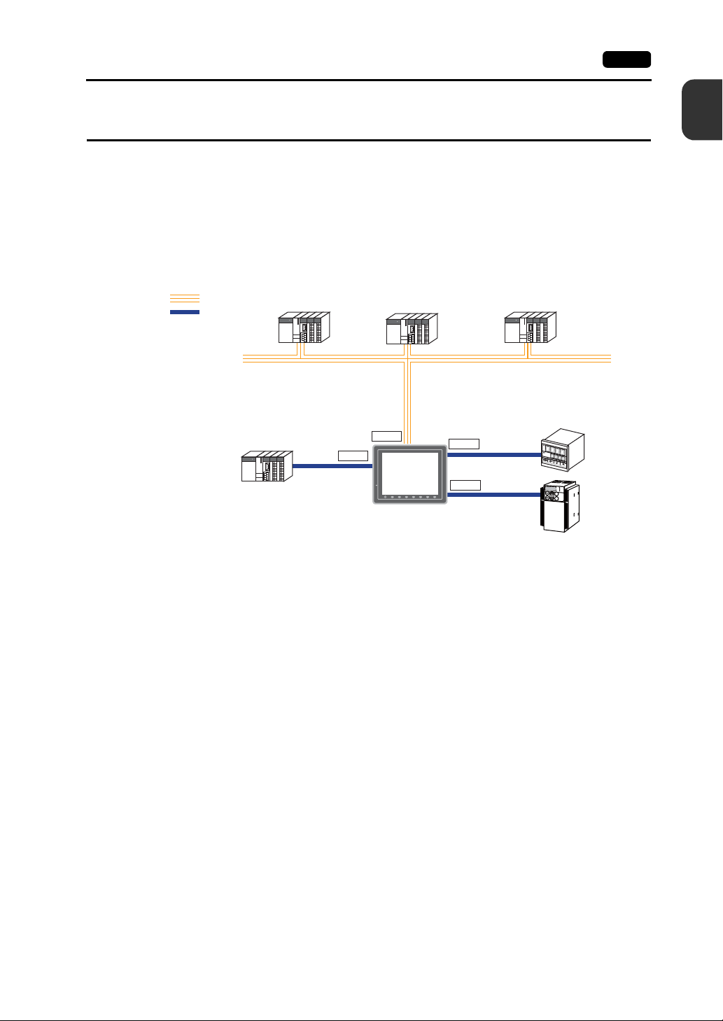
1. 8-way communication
A maximum of eight controllers, such as PLCs or peripheral equipment, of different models and
manufacturers can be connected to one V8 series via mixed network of Ethernet (max. 8
protocols) and serial communications (max. 3 protocols).
The V8 series can communicate with eight types of devices at one time and can exchange data
among connected devices.
Connection example: serial 3 ports + Ethernet
Ethernet
Serial
Manufacturer
A
CN1
LAN
1
Product Outline
A maximum of 5 types
of devices can be
connected.
Manufacturer
B
MJ1
V8
MJ2
SYSTEM
F 7F 6F 5F 4F 3F 2F 1
Manufacturer
C
K
E
Y
P
A
D
Hz
C
O
N
T
R
O
L
A
P
R
O
M
O
D
E
KW
PRG
R
E
S
E
T
R
U
N
FUNC
D
A
T
A
S
T
O
P
Inv
er
te
r
Ethernet
2. 65536-color display
A high-definition display of 65,536 colors (without blinks, 32,768 colors with blinks) is possible.
Photographs (JPEG) or illustrations (bitmap) are displayed close to the real image. An operator
can view operating conditions easily because of the increased viewability.
3. 16770k-color display & 30-frame display per second for video (V812iS/V810iS/V810iT/V808iS
only)
Video image is displayed in 16770k-color and with 30 frames per second.
Even if takt time is short, the video image can be displayed in real time.
* For V808iS: 260k-color
4. Stroke font
Unlike standard bitmap fonts, the font size can be adjusted as desired regardless of the display
resolution. Quality expression is possible.
5. Process for screen data creation is reduced with use of “component parts”.
A “component part” is a part which consists of multiple components having different functions or
different macro programs.
Screen data with advanced functions can be created easily and rapidly.
6. CF-card 2 drives provided
CF cards can be used at the same time in both built-in CF interface and USB-CFREC.
Data can be transmitted between two CF cards. You can use CF cards for various purposes as
required.
7. PictBridge-compatible printer available
A PictBridge-compatible printer can be connected.
Simple printing using a USB cable is possible.
Page 17
1-2 2. Models and Peripheral Equipment
2. Models and Peripheral Equipment
MONITOUCH Models
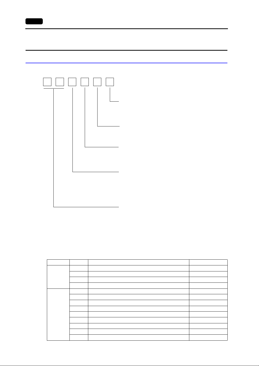
The model name consists of the following information.
V8
Power supply specification
None: 100 - 240 VAC specification
D: 24 VDC specification
(CE/UL/cUL approved)
Touch switch specification
None: Analog
M: Matrix
Device specification
S: TFT color LCD (SVGA)
T: TFT color LCD (VGA)
C: TFT color LCD (VGA)
Functional specification
i: High-performance type
(With built-in LAN port and optional unit port
None: Standard type
(Without built-in LAN port nor
optional unit port)
Screen size
12: 12.1-inch
10: 10.4-inch
08: 8.4-inch
* V810iC/ V808iC: without optional unit port
The following models are available.
Analog resistance film type
Series Model Specifications Remarks
V812S TFT color, 800 × 600 dots, standard, AC power supply
V812 series
12-inch
V810 series
10-inch
V812SD TFT color, 800 × 600 dots, standard, DC power supply CE/UL/cUL approved
V812iS TFT color, 800 × 60 0 dot s, h igh-performan ce, AC power supply
V812iSD TFT color, 800 × 600 dots, high-perf ormance, DC power supply CE/UL/cUL approved
V810S TFT color, 800 × 600 dots, standard, AC power supply
V810SD TFT color, 800 × 600 dots, standard, DC power supply CE/UL/cUL approved
V810iS TFT color, 800 × 60 0 dot s, h igh-performan ce, AC power supply
V810iSD TFT color, 800 × 600 dots, high-performance, DC power supply CE/UL/cUL approved
V810T TFT color, 640 × 480 dots, standard, AC power supply
V810TD TFT color, 640 × 480 dots, standard, DC power supply CE/UL/cUL approved
V810iT TFT color, 640 × 480 dots, high-perf ormance, AC power supply
V810iTD TFT color, 640 × 480 dots, high-performance, DC power supply CE/UL/cUL approved
V810C TFT color, 640 × 480 dots, standard, AC power supply
*
)
Page 18
2. Models and Peripheral Equipment 1-3
Series Model Specifications Remarks
V810 series
10-inch
V808 series
8-inch
V810CD TFT color, 640 × 480 dots, standard, DC power supply CE/UL/cUL approved
V810iC TFT color, 640 × 480 dots, high-p erforman ce, AC power supply
V810iCD TFT color, 640 × 480 dots, high-performance, DC power supply CE/UL/cUL approved
V808SD TFT color, 800 × 600 dots, standard, DC power supply
V808iSD TFT color, 800 × 600 dots, high-performance, DC power supply
V808CD TFT color, 640 × 480 dots, standard, DC power supply
V808iCD TFT color, 640 × 480 dots, high-performance, DC power supply
CE/UL/cUL approved
Matrix resistance film type
Series Model Specifications Remarks
V812SM TFT color, 800 × 600 dots, standard, AC power supply
V812 series
12-inch
V810 series
10-inch
V812SMD TFT color, 800 × 600 dots, standard, DC power supply CE/UL/cUL approved
V812iSM
V812iSMD
V810TM TFT color, 640 × 480 dots, standard, AC power supply
V810TMD TFT color, 640 × 480 dots, standard, DC power supply CE/UL/cUL approved
V810iTM
V810iTMD
V810CM TFT color, 640 × 480 dots, standard, AC power supply
V810CMD TFT color, 640 × 480 dots, standard, DC power supply CE/UL/cUL approved
V810iCM
V810iCMD
TFT color, 800 × 600 dots, high-performance, AC power
supply
TFT color, 800 × 600 dots, high-performance, DC power
supply
TFT color, 640 × 480 dots, high-performance, AC power
supply
TFT color, 640 × 480 dots, high-performance, DC power
supply
TFT color, 640 × 480 dots, high-performance, AC power
supply
TFT color, 640 × 480 dots, high-performance, DC power
supply
CE/UL/cUL approved
CE/UL/cUL approved
CE/UL/cUL approved
1
Product Outline
Page 19
1-4 2. Models and Peripheral Equipment
Peripheral Equipment
The following devices are available as options for the V8 series.
Drawing Tool
V-SFT-5 (configuration software: English version)
Application software for editing screen data for MONITOUCH.
(Windows98SE/NT4.0/Me/2000/XP/XP 64 Edition/Vista 32-bit compatible)
V-CP (screen data transfer cable) 3 m
Used for connection between the V8 series and a computer, or a computer and the card
recorder (CREC).
Optional Unit
GU-xx
Optional unit for the V812iS/ V810iS/ V810iT/ V808iS
GU-00 → Video input (4 channels) + sound output (1 channel)
GU-01 → RGB input (1 channel) + sound output (1 channel)
GU-02 → RGB output (1 channel) + sound output (1 channel)
GU-03 → Sound output (1 channel)
GU-10 → Video input (2 channels) + RGB input (1 channel)
GU-11 → RGB input (2 channels)
Communication Interface Unit
CU-xx
Communication unit used for each network
CU-00 → OPCN-1
x1
x10
SD
T2
T1
CU-01 → T-LINK
CU-02 → CC-LINK
CU-03-3 → Ethernet
CU-04 → PROFIBUS-DP
CU-06 → SX BUS
CU-07 → DeviceNet (I/F driver under development)
CU-08 → FL-NET
Cable
V6-BCD (barcode reader connection cable) 3 m
Used for connection between the V8 series and a barcode reader.
V6-MLT (multi-link 2 master cable) 3 m
Used for multi-link 2 connection between the V8 master station and the V8 slave sta tion.
Page 20
2. Models and Peripheral Equipment 1-5
V6-TMP (connection cable for controllers)
Used for connection between the V8 series and a controller.
V6-TMP: 3 m
V6-TMP-5M: 5 m
V6-TMP-10M: 10 m
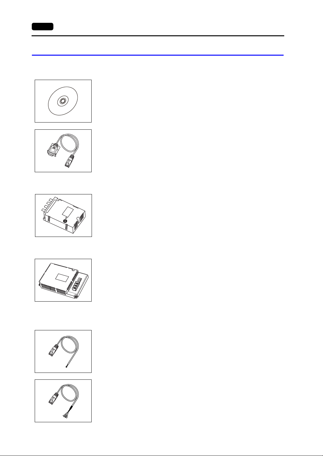
D9-D25 (D-sub9 to D-sub25 conversion cable) 0.1 m
Conversion cable for use of the communication cable used at CN1 (D-sub 25 pin) of the
V6/V7 series at CN1 (D-sub 9 pin) of the V8 series
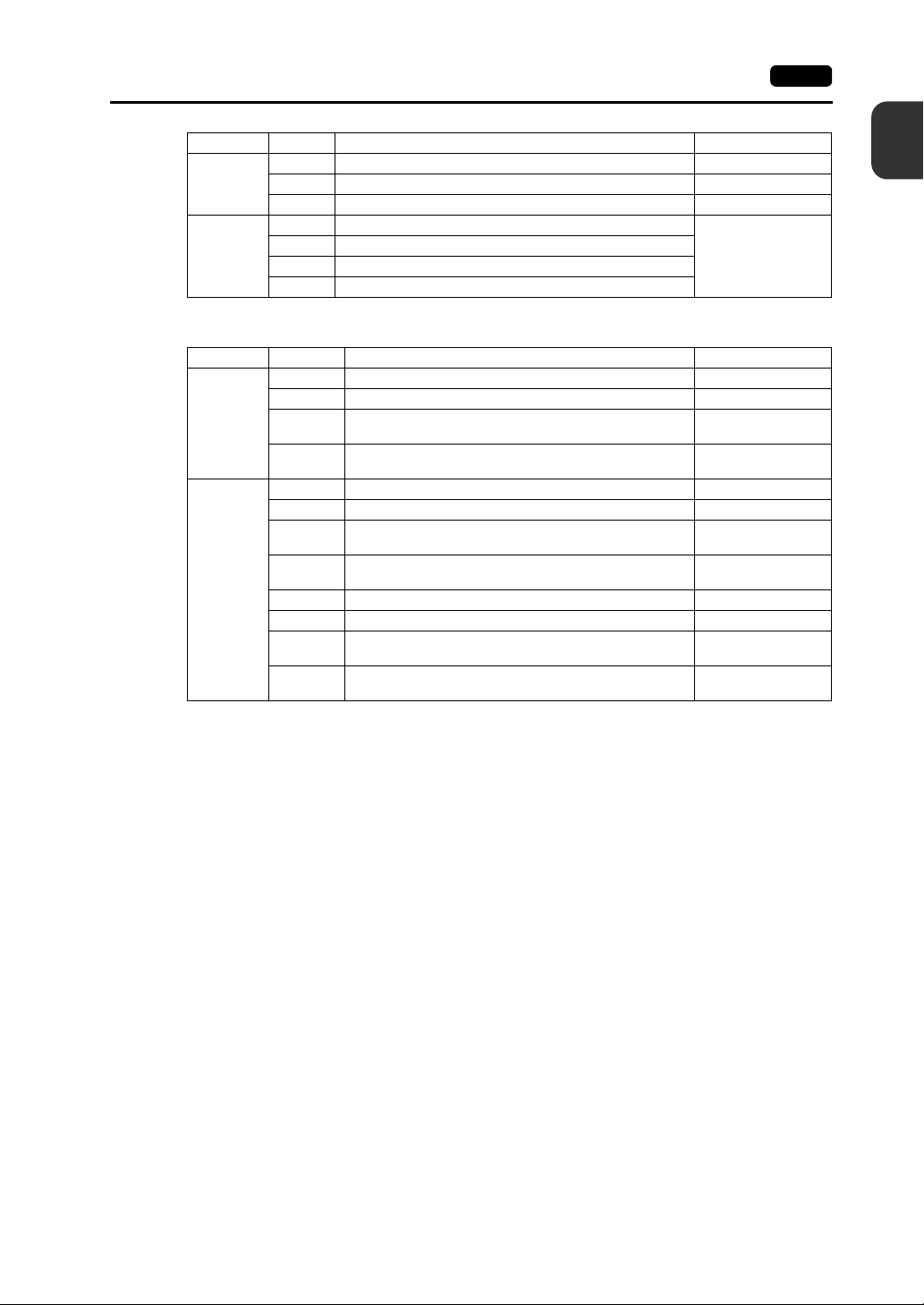
UA-FR (for USB-A port) 1 m
Cable for USB-A (master), with which connection from the front of the control cabinet is
possible.
UB-FR (for USB-B port) 1 m
Cable for USB-B (slave), with which connection from the front of the control cabinet is
possible.
1
Product Outline
Protective Sheet
Other Options
V8xx-GS
Used for protecting the operation panel surface (5 pcs./set).
V812-GS → V812 series
V810-GS → V810 series
V808-GS → V808 series
V8xx-GSN10
Used for protecting the operation panel surface (5 pcs./set, anti-glare treated).
The sheet is colored in light gray and has graininess on its surface to avoid light reflection.
V812-GSN10 → V812 series
V810-GSN10 → V810 series
V808-GSN10 → V808 series
V7-BT (replacement battery)
Replacement lithium battery for the V8 series, V7 series and V606e.
Page 21
1-6 2. Models and Peripheral Equipment
V8xxx-FL (replacement backlight for TFT)
Replacement backlight for the V8 series.
V812-FL → V812 series
V810-FL → V810S/V810T/V810C series
V808S-FL → V808S series
V808C-FL → V808C series
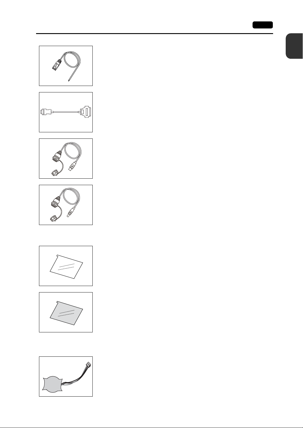
TC-D9 (terminal converter)
Used for connection between the V8 series and a controller at the RS-422/485 terminal
+5V
SG
+SD
-SD
+RD
-RD
FG
block via CN1 (D-sub 9-pin).
V-MDD (ACPU/QnACPU/FXCPU dual port interface)
Add-on connector with two ports, specifically desi gned for the connector on the
V
-
M
GPP
D
1 2 3
D
GD
MITSUBISHI’s ACPU/QnACPU/FXCPU programmer. Operability can be improved when
directly connecting the V8 series to the ACPU/QnACPU/FXCPU programmer.
V-I/O (serial extension I/O)
DC24V
IN1 IN3
FG
IN5
IN0 IN2
IN7 IN9
IN4
IN11
IN6
IN13 IN15
IN8
IN10
IN12
IN14
COM+
OUT0
OUT1 OUT3 OUT5 OUT7
OUT2 OUT4
MJ1
OUT8 OUT10
OUT6 COM1
OUT12 OUT14
OUT9
COM2
OUT11
OUT13
OUT15
Used as an external I/O unit. It has 16 inputs and 16 outputs.
Card Recorder
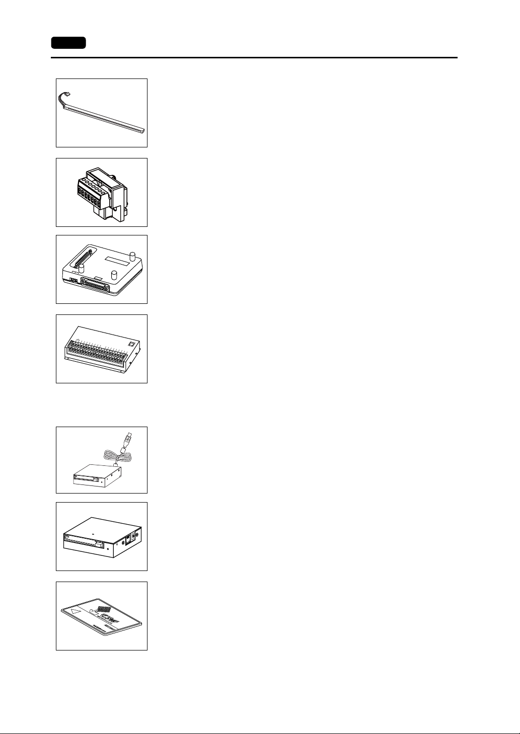
USB-CFREC (USB CF card recorder)
Unit that connects to the USB-A port of the V8 series and makes a CF card available.
CREC (card recorder)
Used for creating a backup copy of screen data or works as an external memory storage
system for memory manager and data logging functions by connecting to the MJ port.
REC-MCARD (memory card compliant with JEIDA ver. 4.0)
Used with the card recorder (CREC) when making a backup copy of screen data or saving
data on an external medium for memory manager and data logging functions.
SRAM 256 K, 512 K, 1 M, 2 M, 4 Mbytes
FLASH ROM 4 Mbytes
Page 22
3. System Composition 1-7
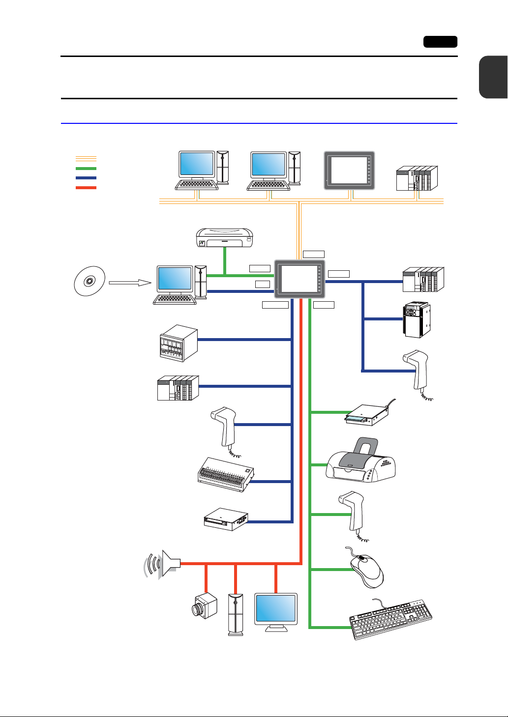
3. System Composition
System Composition of V8i/V8iC Series
The following illustration shows possible system configurations using the V8i/V8iC series.
Ethernet
USB
Serial
Optional unit
V series
configuration
software
"V-SFT-5"
Temperature
controller, inverter
Computer (PC)
Printer (PictBridge)
PictBridge
Creating screens
Computer (PC)
Computer (PC)
"V-CP"
Transferring
screen data
"V6-TMP"
USB-B
MJ1
V8i
LAN
1
Product Outline
SYSTEM
F 1
F 2
F 3
F 4
V8i
F 5
F 6
F 7
Ethernet
PLC/general-purpose
SYSTEM
F 1
F 2
F 3
F 4
F 5
F 6
F 7
CN1
Communication
cables
USB-AMJ1/MJ2
computer
K
E
Y
P
A
D
Hz
C
O
N
T
R
O
L
A
P
RO
M
O
D
E
KW
PRG
R
E
S
E
T
R
U
N
FUNC
D
A
T
A
S
T
O
P
Inve
rte
r
Temperature controller,
inverter
PLC
"V6-BCD"
Barcode reader
Serial extension I/O unit
"V-I/O"
N
5
I
N
0
I
N
7
I
N
2
IN
4
I
N
6
I
N
8
M
J
I
N
9
I
N
1
1
I
N
1
1
I
N
1
3
I
N
1
5
0
I
N
1
O
2
U
T1
I
N
O
1
U
4
T
3
C
O
O
M
U
+
T
5
O
U
O
T
U
0
T7
O
U
O
T2
U
T
8
O
U
O
T4
U
T
1
0
O
O
U
U
T
6
T1
2
C
O
O
M
U
1
T
14
O
U
C
T
O
9
M
2
O
U
T
1
1
O
U
T
13
O
U
T
1
5
D
C
2
4
V
I
N
1
F
G
I
N
3
I
Card recorder
"CREC"
Speaker
(Sound output)
Video camera
(Video input)
Computer (RGB input)
Display (RGB output)
*1 For the V8i series only. The option unit (GU-xx) is required.
Barcode reader
USB CF card recorder
"USB-CFREC"
Printer
Barcode reader
*1
Mouse
Keyboard
Page 23
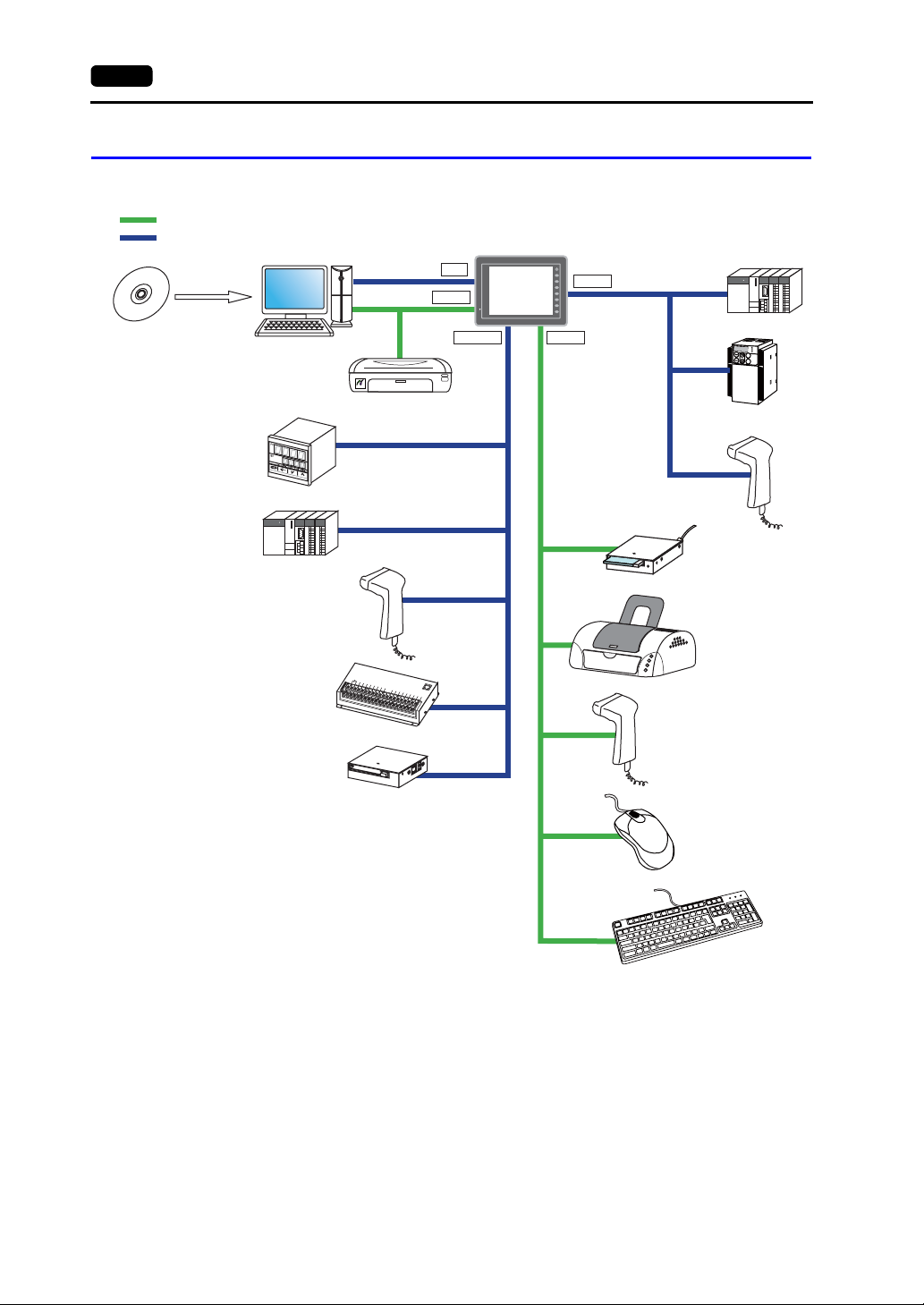
1-8 3. System Composition
System Composition of V8/V8C Series
The following illustration shows possible system configurations using the V8/V8C series.
USB
"V-SFT-5"
V series
configuration
software
Serial
Creating screens
Temperature
controller, inverter
PLC
Barcode reader
Transferring screen data
"V-CP"
USB-B
PictBridge
Printer (PictBridge)
"V6-TMP"
"V6-BCD"
MJ1
V812S
V8
V810S/T/C
V808S/C
SYSTEM
F 1
F 2
F 3
F 4
F 5
F 6
F 7
USB-AMJ1/MJ2
CN1
Communication
cables
PLC/general-purpose
computer
Temperature
controller, inverter
K
E
Y
P
A
D
Hz
C
O
N
T
R
O
L
A
P
R
O
M
O
D
E
KW
PRG
R
E
S
E
T
R
U
N
FUNC
D
A
T
A
S
T
O
P
In
ve
r
te
r
Barcode reader
USB CF card recorder
"USB-CFREC"
Serial extension I/O unit
"V-I/O"
Card recorder
"CREC"
Printer
D
C
2
4
V
I
N
1
F
G
I
N
3
I
N
5
I
N
0
I
N
7
IN
2
IN
4
I
N
6
I
N
8
M
I
N
9
I
N
1
0
J1
IN
1
1
IN
1
3
IN
1
5
IN
1
O
2
U
T
1
I
N
O
1
U
4
T
3
C
O
O
M
U
+
T
5
O
U
O
T0
U
T
7
O
U
O
T
U
2
T
8
O
U
O
T4
U
T
1
0
O
O
U
U
T
6
T
1
2
C
O
O
M
U
1
T1
4
O
U
C
T
O
9
M
2
O
U
T
1
1
O
U
T
1
3
O
U
T
15
Barcode reader
Mouse
Keyboard
Page 24

2
1. Specifications
2. Dimensions and Panel Cut-out
3. Names and Functions of Components
4. Serial Connector (CN1)
5. Modular Jack (MJ1 / MJ2)
6. USB Connector
7. LAN Connector (LAN)
8. CF Card
Specifications
Page 25

Page 26
1. Specifications
1. Specifications 2-1
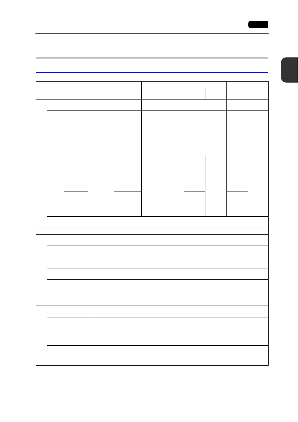
General Specifications
Item
CE Marking -
UL/cUL -
Standards
Permissible Range
of Voltage
Permissible
Momentary Power
Failure
Power Consumption
(Maximum Rating)
to “i”
“a”
Power Supply
Rush
Current
“j” or later
Withstand Voltage
Insulation Resistance 500 VDC, 10 MΩ or above
Surrounding Air
Temperature
Storage Surrounding
Air Temperature
Surrounding Air
Humidity
Storage Surrounding
Air Humidity
Altitude 2000 m or less
Physical Environment
Atmosphere No corrosive gas, no excessive dust, and no conductive dust
Contamination
*6
Level
Vibration Resistance
Working
Shock Resistance
Mechanical
Noise Resistance
100 - 240
VAC ± 10 %
(47 to 63 Hz)
Within 20 ms
70 VA or
less
For 100
*3
VAC:
20 A, 10 ms
or less
For 200
VAC:
*3
40 A, 10 ms
or less
AC external terminals to FG: 1500 VAC, 1 minute
DC external terminals to FG: 500 VAC, 1 minute
0 °C to +50 °C
−10 °C to +60 °C
85 % RH or less (without dew condensation, max. wet-bulb temperature: 39 °C or less)
85 % RH or less (without dew condensation, max. wet-bulb temperature: 39 °C or less)
Contamination level: 2
Vibration frequency: 10 to 150 Hz, acceleration: 9.8 m/s
X, Y, Z: 3 directions for one hour
Pulse shape: sine half wave, peak acceleration: 147 m/s
Noise voltage: 1500 Vp-p, pulse width: 1 μs, rising time: 1 ns
(Measured by using a noise simulator.)
V812 V810 V808
V812xS V812xSD
EN61000-6-2
EN61000-6-4
UL508
*1
UL1604
24 VDC ±
*2
10 %
For 24 VDC:
Within 1 ms
30 W or less
For 24 VDC:
20 A, 2 ms or
less
For 24 VDC:
30 A, 1 ms or
less
*4
V810xS
V810xT
100 - 240 VAC
± 10 %
(47 to 63 Hz)
Within 20 ms
70 VA or
less
For 100
VAC:
20 A,
10 ms or
less
For 200
VAC:
40 A,
10 ms or
less
V810xC
-
-
60 VA or
less
For 100
VAC:
16 A,
6 ms or
less
For 200
VAC:
32 A,
7 ms or
less
V810xSD
V810xTD
EN61000-6-2
EN61000-6-4
UL508
UL1604
24 VDC ± 10 %
For 24 VDC:
Within 1 ms
25 W or
less
For 24
VDC:
20 A,
2 ms or
less
For 24
VDC:
30 A,
1 ms or
less
2
2
V810xCD V808xSD V808xCD
EN61000-6-2
EN61000-6-4
*2
UL508
*1
UL1604
24 VDC ± 10 %
For 24 VDC:
Within 1 ms
23 W or
less
For 24
VDC:
20 A,
2 ms or
less
For 24
VDC:
30 A,
1 ms or
less
20 W or
less
For 24
VDC:
20 A,
1 ms or
less
*5
*5
*1
20 W or
less
For 24
VDC:
20 A,
1 ms or
less
(1.0 G), half-amplitude: 0.075 mm,
(15 G), X, Y, Z: 3 directions six times each
2
Specifications
*2
Static Electricity
Condition
Discharge
Resistance
Electrical Working
Compliant with IEC61000-4-2, contact: 6 kV, air: 8 kV
Page 27
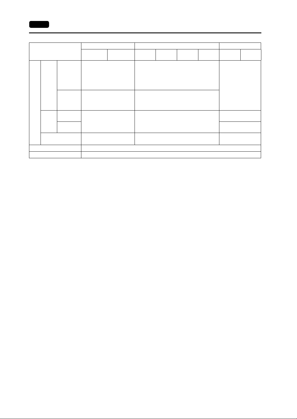
2-2 1. Specifications
Item
“a” to “i”
V812xS V812xSD
*3
Approx. 2.9 kg
Weight
Analog resistance film type
Approx. 2.4 kg
*3
Mounting
Conditions
Dimensions
W × H
× D
Panel Cut-out
Dimensions
“j” or later
“a” to “i”
“j” or later
Matrix resistance film type
Approx. 2.8 kg
*3
326.4 × 259.6 × 69.0 mm 303.8 × 231.0 × 69.0 mm
*3
+0.5
313.0 × 246.2 mm 289.0 × 216.2 mm
−0
Case Color Gray
Material PC/ABS resin
*1 The hardware version “a” to “i” is only approved. For more information on the hardware version, refer to
page 7-3.
*2 Use the Class 2 power supply for the 24-VDC power unit.
*3 This is the hardware version for the V8 unit. For more information on the hardware version, refer to page 7-3.
*4 Sorrounding air temperature is 0 °C to + 45 °C when applying for UL listing using V810 series, hardware
version “j” or later.
*5 Use MONITOUCH in the environment whose wet-bulb temperature is 39 °C or less. Otherwise, MONIT O UCH
may be damaged.
*6 This is an index that expresses the degree of conductive contamination in the environment where
MONITOUCH is used.
“Contamination level 2” indicates the condition where only non-conductive contamination occurs. However,
due to condensation, temporary conductive contamination may occur.
V812 V810 V808
V810xS
V810xT
Analog resistance film type
Matrix resistance film type
V810xC
V810xS/ V810xT: Approx. 2.5 kg
V810xC: Approx. 2.2 kg
V810xT: Approx. 2.5 kg
V810xC: Approx. 2.6 kg
V810xSD
V810xTD
V810xCD V808xSD V808xCD
Approx. 1.5 kg
V810xS/ V810xT: Approx. 2.1 kg
233.0 × 178.0 × 65.8
mm
233.0 × 178.0 × 65.6
mm
+0.5
220.5 × 165.5
+0.5
−0
+0.5
−0
+0.5
−0
mm
−0
+0.5
−0
About UL/cUL Approval
The V8 series (DC power supply type) is UL/cUL-approved.
(File No.: E313548 (UL508), File No.: E315977 (UL1604))
The V8 series conforms to the following four standards.
• UL 508 : Industrial Control Equipment
• UL1604 : Electrical Equipment for Use in Class I, Division 2 Hazardous Locations
• CSA-C22.2 : No. 142-M1987 Process Control Equipment
• CSA-C22.2 No. 213-M1987 : Non-Incendive Electrical Equipment for Use in Class I, Division 2
Hazardous Locations
UL1604/CSA-C22.2 No. 213 Compliance and Handling Cautions
• Power, input and output wiring must be in accordance with Class I, Division 2 wiring methods -
Article 501 - 10(B) of the National Electrical Code, NFPA 70.
• This product is certified for use in Class I, Division 2, Groups A, B, C or D hazardous location or
non-hazardous locations.
• WARNING: Explosion Hazard: Substitution of components may impair compliance to Class I,
Division 2.
• WARNING: Explosion Hazard: Do not disconnect the device while the circuit is alive unless area is
known to be non-hazardous. Perform system set-up or diagnostics of the CF card port, USB-A
and USB-B port only in a non-hazardous location.
• WARNING: Explosion Hazard: For use in a hazardous location, turn off the power before replacing
or wiring modules.
• Do not replace a battery in a hazardous location.
• In the case of use in a hazardous location, be sure to check that the externally connected unit and
each interface have been secured with screws or have been locked. In a hazardous location, it is
impossible to insert or remove a cable from the applicable port. Be sure to check that the location
is non-hazardous before inserting or removing it.
Page 28
UL Listing Application for a System Equipped with the V8 Series
CE Marking
1. Specifications 2-3
• The back panel of the V8 series is not approved as an enclosure. For UL listing application, build
the V8 series in the system, and configure an enclosure so that the entire system will be
UL-approved.
• Use the V8 series indoors only.
• For use on a flat surface of a type 1 enclosure
• In the case of the V812/V810 series, use a UL-approved crimp-style terminal for wiring of the
power supply cable.
Model
V812/V810 M3.5 0.8 N•m AWG16 - 18
• In the case of the V808 series, use naked wires for wiring of the power supply cable.
Model
V808 M3.5 0.8 N•m AWG14 - 16
• Use the Class 2 power supply for the 24-VDC power unit.
• The V8 series (DC power supply type) complies with the following EMC Directives:
EN61000-6-2, EN61000-6-4
• The V8 series is identified as a class-A product in an industrial environment. In the case of usage
in a domestic environment, the V8 series is likely to cause electromagnetic interference.
Appropriate preventive measures should be taken.
Screw Size Tightening Torque
Screw Size Tightening Torque
Terminal Screw
Terminal Screw
Power Cable
Power Cable
2
Specifications
Page 29
2-4 1. Specifications
Installation Specifications
Item Specifications
Grounding Less than 100Ω, FG/SG separated
Protection Structure
Cooling System Cooling naturally
Structure Inserted in a mounting panel
Appropriate Mounting Panel Thickness 1.5 to 5 mm
Front Panel
Rear Case Compliant with IP20
*1 Protection structure for the front when the V8 seri es is mounted on the mounting panel
*2 It is recommended to use the mounting panel who se th ickness ( steel , st a inless) is 3 .0 mm or mor e t o keep th e
unit compliant with IP65. The strength differs depending on the material of the mount ing panel. Check the
environment where the V8 series is used.
*1
Compliant with IP65 (when using waterproof gasket)
*2
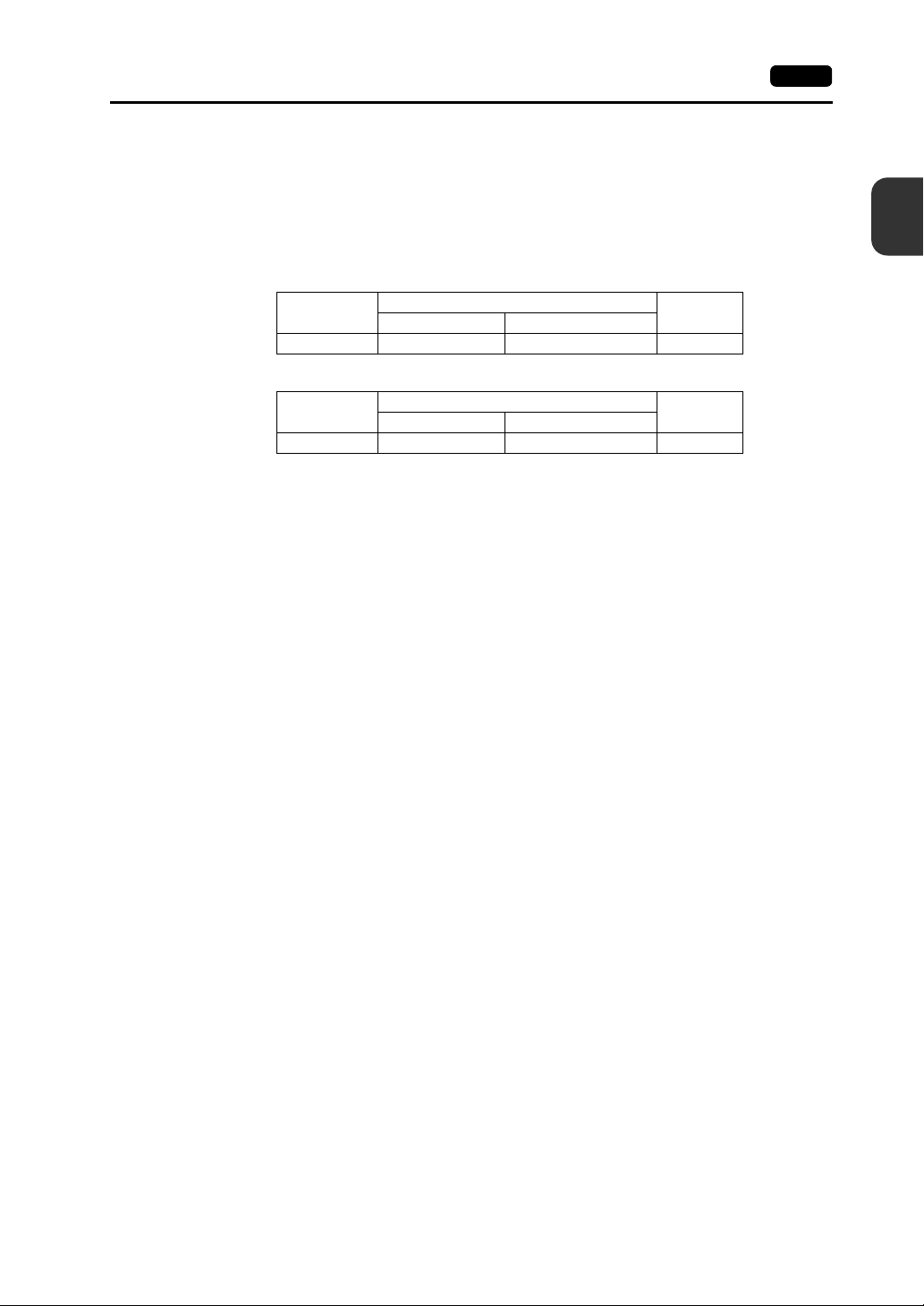
Display Specifications
Item V812xS V810xS V810xT/ V810xC V808xS V808xC
Display Device TFT color
Display Size 12.1-inch 10.4-inch 8.4-inch
Colors 65,536 colors (without blinks) / 32,768 colors (with blinks)
Display Resolution (W × H) 800 × 600 dots 640 × 480 dots 800 × 600 dots 640 × 480 dots
Dot Pitch (W × H)
Backlight Cold cathode tube
Backlight Life
(average life of backlight only)
Backlight Auto OFF Function Always ON, random setting
Brightness Adjustment Function switch: 3 levels / Macro: 128 levels
Surface Sheet Material Polycarbonate, 0.3 mm thick
POWER Lamp
0.3075 × 0.3075 mm0.264 × 0.264
Approx. 50,000 hours (at the normal temperature of 25°C)
ON: Normal (green)
Blink: Backlight error
mm
0.33 × 0.33 mm
0.213 × 0.213 mm0.267 x 0.267
mm
Touch Switch Specifications
Item Analog Resistance Film Type Matrix Resistance Film Type
Number of Switches 1024 × 1024
Mechanical Life One million activations or more
Surface Treatment Hard-coated, anti-glare treat ment 5%
Function Switch Specifications
Item Specifications
Number of Function Switches 8 pcs.
Method Matrix resistance film type
Mechanical Life One million activations or more
12-inch: 50 × 30
10-inch: 40 × 24
Page 30
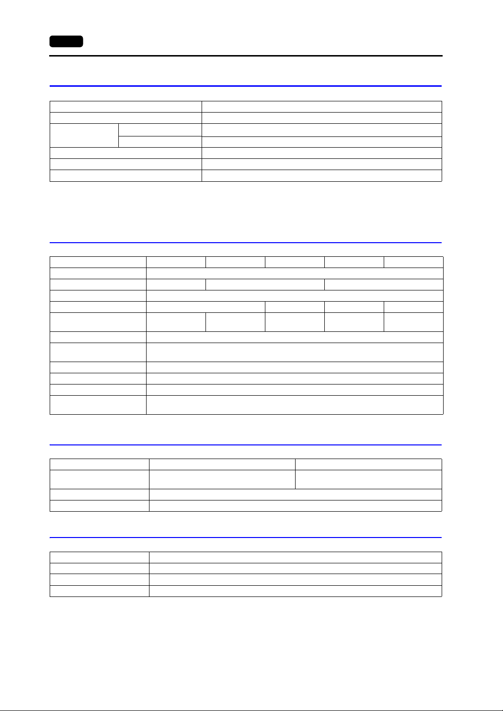
Interface Specifications
Item Specifications
Applicable Standards RS-232C, RS-422/485
Synchronization Asynchronous type
Data Length 7- or 8-bit
D-sub 9-pin (CN1)
Modular Jack 8-pin
(MJ1/MJ2)
USB Connector
(USB-A/B)
Ethernet Port
100BASE-TX/10BA
SE-T
(LAN)
CF Card Interface
Extensional Communication Port (CN5)
Optional Unit Port (CN7)
Parity None, odd, even
Stop Bit 1- or 2-bit
Baud Rate
Applications PLC, temperature controller, barcode reader, etc.
Applicable Standards RS-232C, RS-485 (2-wire connection)
Applications
Applicable
Standards
Baud Rate Low speed: 1.5 Mbps, full speed: 12 Mbps
USB-A
Applications Printer (EPSON STYLUS PHOTO series), USB-CFREC, keyboard, mouse, etc.
Applicable
Standards
Baud Rate Low speed: 1.5 Mbps, full speed: 12 Mbps
USB-B
Applications Screen data transfer, PictBridge-compatible printer
Applicable Standards Compliant with IEEE802.3u (100BASE-TX), IEEE802.3 (10BASE-T)
Baud Rate 10 Mbps, 100 Mbps
Recommended Cable 100Ω UTP (unshielded twist-pair cable), category 5, max. 100 m long
Applications PLC connection, etc.
* For details, refer to the V8 Series Connection Manual.
1. Specifications 2-5
4800, 9600, 19200, 38400, 57600, 76800, 115k bps
(187500 bps for MPI connection
Screen data transfer (MJ1), PLC, temperature contro ller, CREC, barcode
reader, V-I/O, Multi-link 2, V-Link, etc.
Compliant with USB version 1.1
Compliant with USB version 1.1
Compliant with CompactFlash
SX Bus, T-Link, Ethernet, CC-Link, PROFIBUS-DP, DeviceNet, etc.
(The communication interface unit “CU-xx” is necessary.)
RGB input/output, video, sound
(The optional unit “GU-xx” is necessary.)
TM
*
)
2
Specifications
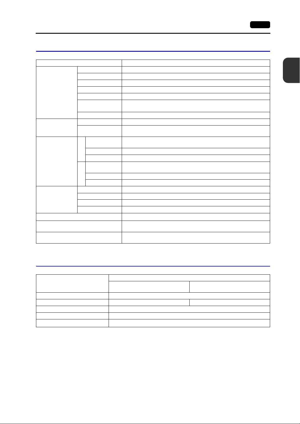
Clock and Backup Memory Specifications
Item
Battery Specification Coin-type lithium primary cell
Backup Memory SRAM 512 kbytes SRAM 128 kbytes
Backup Period 5 years (ambient temperature at 25°C)
Battery Voltage Dr op Detection Provided (internal memory of $s167 allocated)
Calendar Accuracy
* Time loss is approximately 90 seconds a month in an ambient temperature of 25°C in the non-energized state
(backup with battery). Depending on the ambient temperature, the calendar may lose 356 seconds or advance
189 seconds in a month at the maximum. Correct the clock periodically.
V812xS/ V810xS/ V810xT/ V810iC/
V808xS/ V808iC
Monthly deviation ±90 sec (ambient temperature at 25°C)
Specifications
*
V810C/ V808C
Page 31

2-6 1. Specifications
Drawing Environment
Item Specifications
Drawing Method Exclusive configuration software
Name of exclusive configuration software: V-SFT-5
Personal computer: Pentium III 800 MHz or above
Drawing Tool
OS: Windows98SE/NT4.0/Me/2000/XP/XP64 Edition/
Capacity of hard disk required: Free space of approx. 850 Mbytes or more
Memory: 512 Mbytes or more
Display: Resolution 1024 × 800 or above
Display Function Specifications
Item Specifications
Interface Language
1/4-size, 1-byte ANK code Latin 1 ASCII code ASCII code ASCII code
Characters
Font
Character
Size
Number of
Displayable
Characters
Character
Properties
Graphics
Graphic
Properties
2-byte 16-dot JIS #1, 2 levels −
2-byte 32-dot JIS #1 level −−−−
*1 In addition, the following fonts are available.
*2 Applicable when Gothic font, Windows font or stroke font is used.
*
1/4-size 8 × 8 dots
1-byte 8 × 16 dots
2-byte 16 × 16 dots or 32 × 32 dots
Enlargement
Factor
Display
Resolution
1/4-size 100 characters × 75 lines 80 characters × 60 lines
1-byte 100 characters × 37 lines 80 characters × 30 lines
2-byte 50 characters × 37 lines 40 characters × 30 lines
Display
properties
Colors 65,536 colors (without blinks) / 32,768 colors (with blinks)
Lines Line, continuous line, box, parallelogram, polygon
Circles Circle, arc, sector, ellipse, elliptical arc
Others Tile patterns
Line types 6 (thin, thick, dot, chain, broken, two-dot chain)
Tile patterns 16 (incl. user-definable 8 patterns)
Display
properties
Colors 65,536 colors (without blinks) 32,768 colors (with blinks)
Color selection Foreground, background, boundary (line)
Gothic, English/Western Europe HK Gothic, English/Western Europe HK Times, Central Europe, Cyrillic,
Greek, Turkish
For more information, refer to the V8 Series Reference Manual.
Japanese
Normal, reverse, blink, bold, shadow, transparent
Normal, reverse, blink
English/Western
Europe
*2
Point
: 8, 9, 10, 11, 12, 14, 16, 18, 20, 22, 24, 26, 28, 36, 48, 72
800 × 600 640 × 480
(Pentium IV 2.0 GHz or above recommended)
Vista 32-bit
Screen color: 16 bits or more
Chinese
(Traditional)
Chinese
(traditional)
Windows font
Stroke font
X: 1 to 8 times, Y: 1 to 8 times
Chinese
(Simplified)
Chinese
(simplified)
Korean
Hangul
(without Kanji)
Page 32

Function Performance Specifications
1. Specifications 2-7
Item
Screens Max. 1024
Screen Memory (Flash memory)
Switch 1024 per screen
Switch Actions
Lamp
Graph
Numerical Data
Display
Data
Setting
Sampling
Graphic Library Max. 2560
Overlap Library Max. 1024
Data Blocks Max. 1024
Messages Max. 32768 lines
Patterns Max. 1024
Macro Blocks Max. 1024
Page Blocks Max. 1024
Direct Blocks Max. 1024
Screen Blocks Max. 1024
Data Sheets Max. 1024
Screen Library Max. 1024
Comments Max. 32767
Device Memory Map Max. 32 × 8 (PLC1 to PLC8)
Time Display Provided
Hard Copy Provided
Buzzer Provided, 2 sounds (short beep, long beep)
Auto OFF Function Always ON, random setting
Self-diagnostic Function
Character
Display
Message Display
*1 The number of setting memory locations is limited to 1024 per screen.
*2 Layer: 4 per screen (base + 3 overlap displays)
V812xS/ V810xS/ V810xT/ V810iC/ V808xS/
Approx. 12.5 Mbytes
(varies depending on the font)
Set, reset, momentary, alternate, to light
(Possible to press a function switch and a switch on the display at the same time)
Reverse, blink, exchange of graphics
1024 per screen
Pie, bar, panel meter and closed area graph:No limitation
Statistics and trend graphs: Max. 256 per layer
No limitation
No limitation
Display Resolution: 800 × 600: Max. 100 characters (1-byte)
No limitation
Sampling display of buffer data
(Constant sampling, bit synchronization, alarm logging, time order alarming, alarm function)
Switch self-test function
Communication parameter set t in g ch eck function
Communication check funct i on
V808iC
640 × 480: Max. 80 characters (1-byte)
Specifications
V810C/ V808C
Approx. 4.5 Mbytes
(varies depending on the font)
*2
2
Specifications
Page 33

2-8 2. Dimensions and Panel Cut-out
2. Dimensions and Panel Cut-out
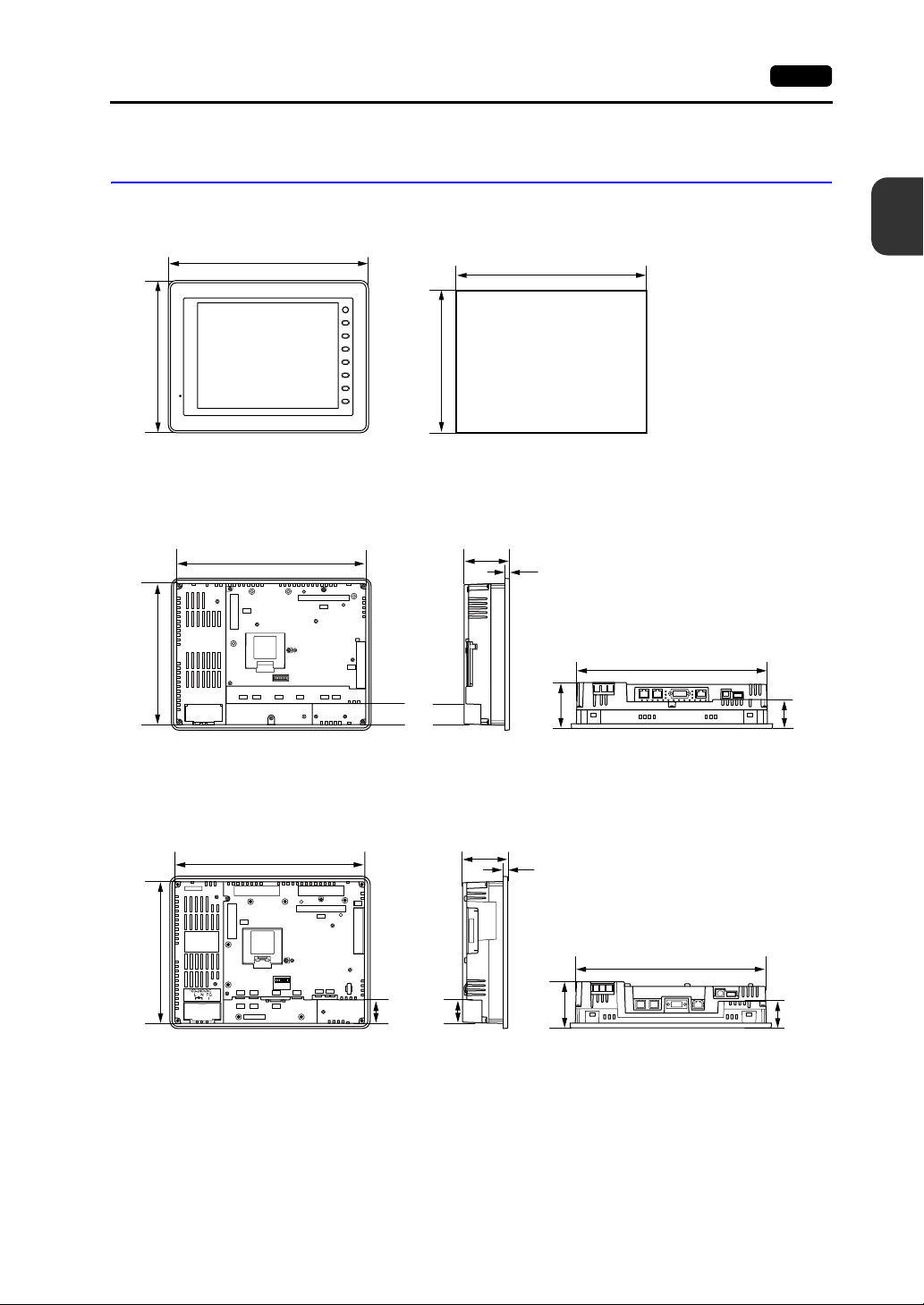
External Dimensions and Panel Cut-out Dimensions for V812S / V812iS
• Front View
326.4
• Panel Cut-out Dimensions
+0.5
313.0
-0
-0
+0.5
259.6
246.2
F 2
F 1
SYSTEM
F 7F 6F 5F 4F 3
Hardware version : a to i
• Rear View • Side View • Bottom View
245.2
312.0
CN5
CN7
CF
U-B U-A
CN1MJ2MJ1
LAN
58.1
69.0
7.0
69.0
(Unit: mm)
312.0
43.5
Hardware version : j or later
• Rear View • Side View • Bottom View
312.0
CN5
CF
CN7
69.0
7.0
245.2
U-B U-A
CN1
MJ1
MJ1
LAN
MJ2
MJ2
CN1
61.23
69.0
* For more information on the hardware version, refer to page 7-3.
312.0
40.0
Page 34
2. Dimensions and Panel Cut-out 2-9
External Dimensions and Panel Cut-out Dimensions for V810S / V810iS / V810T / V810iT
• Front View
231.0
303.8
SYSTEM
F1
F2
F3
F4
F5
F6
F7
• Panel Cut-out Dimensions
+0.5
289.0
-0
-0
+0.5
216.2
Hardware version : a to i
• Rear View • Side View • Bottom View
69.0
7.0
69.0
215.2
CN5
MJ1
288.0
MJ2
CN7
CF
LAN
CN1
U-AU-B
31.47
288.0
(Unit: mm)
43.5
2
Specifications
Hardware version : j or later
• Rear View • Side View • Bottom View
69.0
7.0
CN5
288.0
CF
CN7
215.2
U-B
CN1MJ1 MJ2
CN1MJ1 MJ2
U-A
LAN
34.43
69.0
* For more information on the hardware version, refer to page 7-3.
288.0
40.0
Page 35

2-10 2. Dimensions and Panel Cut-out
External Dimensions and Panel Cut-out Dimensions for V810C / V810iC
• Front View
231.0
• Rear View
215.2
CN5
303.8
288.0
CN1MJ1 MJ2
(Unit: mm)
SYSTEM
F1
F2
F3
F4
F5
F6
F7
• Side View
69.0
7.0
CF
U-B
U-A
LAN
35.2
• Bottom View
69.0
288.0
46.3
• Panel Cut-out Dimensions
289.0
-0
+0.5
216.2
+0.5
-0
Page 36

2. Dimensions and Panel Cut-out 2-11
External Dimensions and Panel Cut-out Dimensions for V808S / V808iS
• Front View
178.0
233.0
SYSTEM
F1
F2
F3
F4
F5
F6
F7
• Panel Cut-out Dimensions
+0.5
220.5
-0
-0
+0.5
165.5
Hardware version : a to i
• Rear View • Side View • Bottom View
220.0
65.8
6.9
CF
CN7
CN5
165.0
24VDC
FG
LAN
U-B
CN1
U-A
MJ2
MJ1
24.3
65.8
(Unit: mm)
2
Specifications
220.0
44.6
Hardware version : j or later
• Rear View • Side View • Bottom View
220.0
CF
CN7
CN5
65.6
6.9
165.0
24VDC
FG
CN1
LAN
U-B
U-A
MJ2
FG
MJ1
24.3
65.6
* For more information on the hardware version, refer to page 7-3.
44.5
Page 37

2-12 2. Dimensions and Panel Cut-out
External Dimensions and Panel Cut-out Dimensions for V808C / V808iC
• Front View
178.0
165.0
(Unit: mm)
233.0
SYSTEM
F1
F2
F3
F4
F5
F6
F7
• Side View• Rear View
65.8
220.0
CF
CN5
24VDC
FG
CN1
U-A
U-B
LAN
MJ1
MJ2
61.8
6.9
12.8
• Bottom View
65.8
220.0
44.6
• Panel Cut-out Dimensions
+0.5
220.5
-0
-0
+0.5
165.5
Page 38

3. Names and Functions of Components 2-13
3. Names and Functions of Components
V812S / V812iS
1
2
F 2
F 1
SYSTEM
F 7F 6F 5F 4F 3
3
V810S / V810iS / V810T / V810iT
1
SYSTEM
F 1
F 2
F 3
3
F 4
F 5
2
F 6
F 7
46 5
8
CN5
MJ1
MJ2
CN7
CF
U-B U-A
CN1
LAN
16
1514131211109
17
678
45
CN5
MJ2
MJ1
CN7
CF
LAN
CN1
U-AU-B
2
Specifications
7
V810C / V810iC
2
16
11 12 13
9
10
14 15
17
1
SYSTEM
F1
F2
F3
3
F4
F5
F6
F7
678
4
CN5
CF
U-B
CN1MJ1 MJ2
U-A
LAN
16
10
11 12 13
9
14 15
17
Page 39

2-14 3. Names and Functions of Components
V808S / V808iS
2
V808C / V808iC
2
1
456
CF
CN7
CN5
3
24VDC
FG
9
LAN
U-B
CN1
12
MJ2
MJ1
13
14 15
10
11
7
16
U-A
8
17
1
SYSTEM
F1
F2
F3
3
F4
F5
F6
F7
4 6
CF
CN5
7
16
24VDC
FG
CN1
9
12
U-B
LAN
MJ1
13
14 15
8
U-A
MJ2
10
11
17
1. Display
This is the display unit.
2. Power lamp (POWER)
Illuminates in green when the V8 series is powered on, and is operating normally. Flashes when
an error occurs to the backlight (burned-out backlight, etc.).
3. Function keys
Used for RUN/STOP selection, brightness adjustment and backlight ON/OFF (setting on the
V-SFT-5 editor required). These switches can be used as user-defined switches in the RUN
mode.
4. Communication interface unit connector (CN5)
This is the connector where the communication unit (“CU-xx”, optional) for OPCN-1, T-LINK,
CC-Link, Ethernet, PROFIBUS-DP, SX Bus or DeviceNet is mounted.
5. Optional unit connector (CN7) V812iS/V810iS/V810iT/V808iS only
Used for mounting the optional unit “GU-xx” for video input, sound output, RGB input or RGB
output.
6. Battery holder
Contains a backup battery for SRAM and clock.
When the battery voltage drops, replace the battery with a new one (V7-BT).
7. CF card connector (CF)
This is the connector where the CF card is inserted. Access to the CF card is enabled when the
cover is closed.
Page 40

3. Names and Functions of Components 2-15
8. DIP switch
8-bit DIP switch used for setting terminating resistance of the CN1 signal line and the MJ1/MJ2
RS-485 signal line.
9. Power supply terminal block
Supplies the power to the V8 series (100 to 240 VAC, 24 VDC).
10. Modular jack 1 (MJ1)
Used for screen data transfer and connection with PLCs or other peripheral devices.
11. Modular jack 2 (MJ2)
Used for connection with PLCs or other peripheral devices.
12. PLC communication connector (CN1)
Used for connection with a controller (PLC, temperature controller, inverter, etc.).
13. 100BASE-TX/10BASE-T connector (LAN) V8i/V8iC series only
Used for Ethernet connection.
14. USB-B (slave port)
Used for screen data transfer or connection with a PictBridge-compatible printer.
15. USB-A (master port)
Used for connection with a printer, a USB CF card recorder
16. USB cable clamp mounting hole
For V810/V812, this hole is used for attaching a USB cable clamp.
For V808, this hole is used for attaching a USB cable tie.
17. Mounting holes
Used for inserting fixtures when securing the V8 series to the mounting panel.
“USB-CFREC”, keyboard, mouse etc.
2
Specifications
Page 41

2-16 4. Serial Connector (CN1)
4. Serial Connector (CN1)
Connector for a Controller
Communication (RS-232C, RS-422/485) with a controller is enabled via the serial connector (CN1).
• For V812/V810 • For V808
Bottom View
The serial connector pins correspond to signals as given below.
CN1 (D-sub 9-pin, fem ale)
Bottom View
5
9
*1
Pin No.
1 NC Not used +RD Receive data (+)
2 RD Receive data -RD Receive data (−)
3 SD Send data -SD Send data (−)
4 NC Not used +SD Send data (+)
5 SG Signal ground SG Signal ground
6 NC Not used +RTS Request to send (+)
7 RTS Request to send -RTS Request to send (−)
8 CTS Clear to send NC Not used
9 NC Not used +5V
*1 The signal level can be changed between RS-232C and RS-422/485 on the configuration software.
When RS-232C is selected, set the DIP switches 5 and 7 to the OFF position.
(For more information on the DIP switch, refer to “Chapter 4”.)
*2 When RS-422/485 is selected, +5V is output from pin No. 9.
+5V is used as the power supply for the external terminating resistance for RS-4 22/485 communication. It
cannot be used as an external power supply.
Signal Contents Signal Contents
RS-232C
1
6
RS-422 / RS-485
*1
Use prohibited
Recommended Connector
The following connector is recommended for a self-made cable.
Recommended
connector
DDK’s 17JE-23090-02(D8C)-CG
D-sub 9-pin / male / inch screw thread (#4-40UNC) type
/ with hood / lead- and cadmium-free
*2
PLC/Temperature Controller Connection
The V8 series can communicate with PLC or temperature controller.
For more information about the connectable device models and the setting on V-SFT-5, refer to the “V8
Series Connection Manual”.
Barcode Reader Connection
The V8 series can receive the barcode data from the connected barcode reader. For more information
about the connectable device models and the setting on V-SFT-5, refer to the “V8 Series Connection
Manual”.
Page 42

5. Modular Jack (MJ1 / MJ2)
5. Modular Jack (MJ1 / MJ2) 2-17
Modular Jack 1 (MJ1) / 2 (MJ2)
A screen data transfer cable (MJ1 only), temperature controller, barcode reader, CREC, or V-I/O can
be connected to the modular jack (MJ1 or MJ2).
• For V812/V810 • For V808
Bottom View Bottom View
Pins of MJ1 and MJ2 correspond to signals as given below.
MJ1/2 Pin No. Signal Contents
8 76 5 43 21
*1 Allowable current for the external power supply +5V at MJ1/MJ2/USB-A of the V8 series
- For MJ1 and MJ2, the maximum allowable current is 150 mA in total.
- When connecting an optional unit or communication unit, be careful not to exceed the total allowable
current for USB-A, MJ1 and MJ2.
Type Optional Unit
V812xS / V810xS
V810xT / V808xS
V812iS / V810iS
V810iT / V808iS
V810xC / V808xC -
1 +SD/RD RS-485 + data
2 −SD/RD RS-485 − data
3+5V
4+5V
5SG
6SG
7 RD RS-232C receive data
8 SD RS-232C send data
None
GU-00 - GU-03
GU-10 / GU-11
Externally supplied +5 V
Signal ground
Communication Unit
(CU-xx)
None
None
Provided 550 mA
None 650 mA
Provided 250 mA
None 500 mA
Provided 150 mA
(MJ1 + MJ2 + USB-A)
2
Specifications
*1
Allowable Current
650 mAProvided
Combined Use of MJ1 and MJ2 Functions
Multi-link 2 and ladder transfer function cannot be used at the same time.
Page 43

2-18 5. Modular Jack (MJ1 / MJ2)
PLC/Temperature Controller Connection
The V8 series can communicate with PLC or temperature controller.
For more information about the connectable device models and the setting on V-SFT-5, refer to the “V8
Series Connection Manual”.
Transferring Screen Data
When transferring screen data, use Hakko Electronics' data transfer cable (V-CP: 3 m) to connect MJ1
of the V8 series to a personal computer.
* Screen data can be transferred via Ethernet or using a CF card in addition to serial transfer.
Connection Example
V8
SYSTEM
* When [MJ1] is selected for [No Connection] on the V-SFT editor, it is possible to transfer data in
the RUN mode because the RUN/STOP mode (on the Main Menu screen) can be automatically
selected. Also, the RUN/STOP mode is automatically selected when the difference program
transfer and the simulator are used.
When an option other than [No Connection] is selected for [MJ1], select the STOP mode (on the
Main Menu screen) and transfer screen data. Simulation or Difference Program Transfer is not
available.
V-SFT-5 Setting
Select [File] → [Transf er] → [Communication Setting], and select “Serial Port” for [Communication
Port] in the [Communication Setting] window.
F 7F 6F 5F 4F 3F 2F 1
Barcode Reader Connection
The V8 series can connect to the barcode reader at the MJ1/2 of the V8 series with Hakko Electronics'
optional cable (V6-BCD: 3 m), and receive the barcode data from it. For more information about the
connectable device models and the setting on V-SFT-5, refer to the “V8 Series Connection Manual”.
MJ1
V-CP
D-sub 9-pin
PC
Page 44
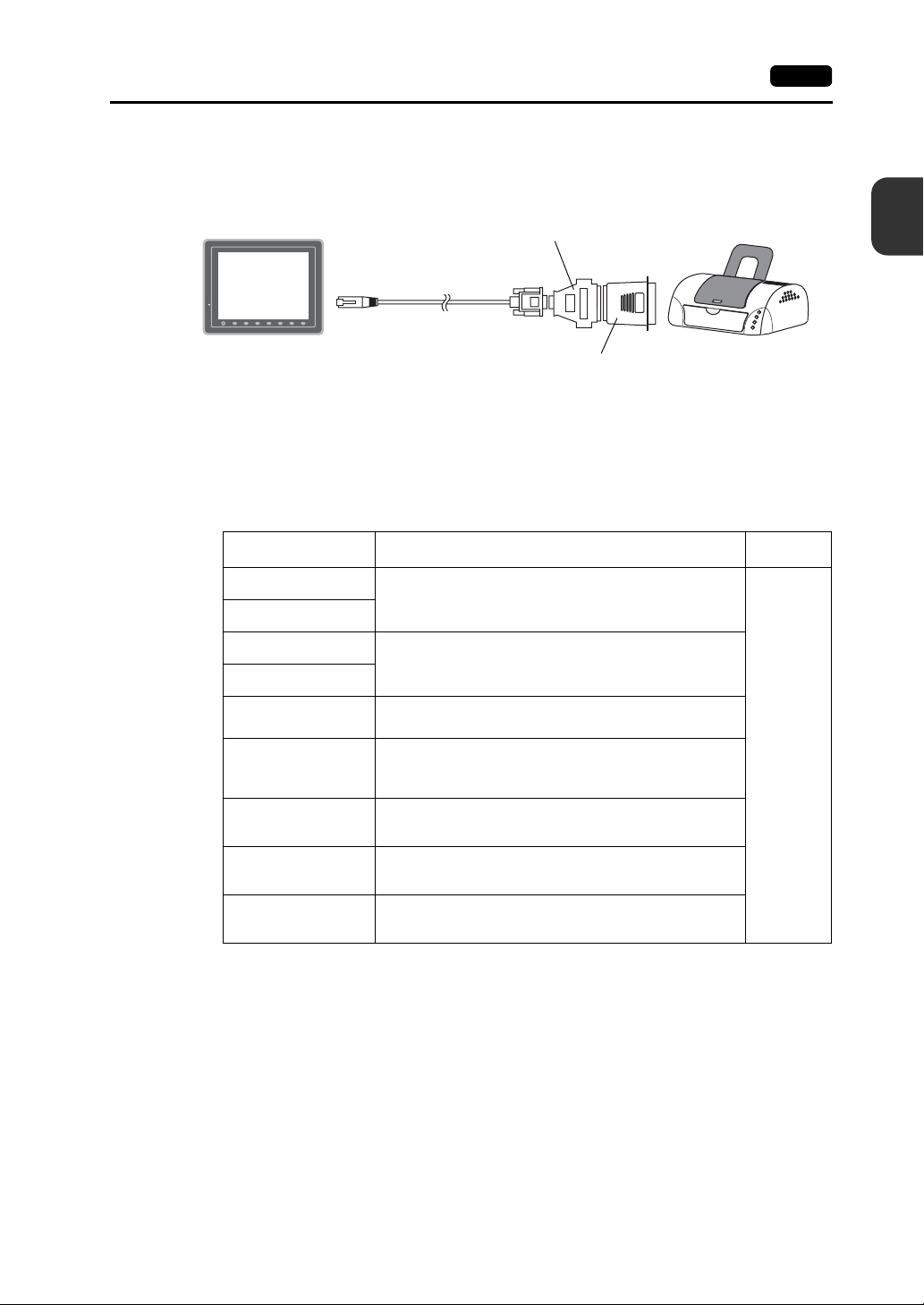
Printer Connection (Serial Printer)
The printer for the serial interface is connected with the MJ1/2 port of the V8 series, and it is possible
to print.
5. Modular Jack (MJ1 / MJ2) 2-19
D-sub 25-pin ←→ 9-pin converter
Parallel port
V8
SYSTEM
*1 Refer to the specification sheet of the printer to be used for the connecting cable for serial interface. For
information on MJ1/MJ2 signals, refer to page 2-17.
*2 To connect to a printer equipped with a p arallel i nterfa ce, u se a commercially available p ara llel-se rial converter.
When the serial connector of the converter is a D-sub 9-pin male connector, use Hakko Electronics’ V-CP
connection cable.
MJ1/2
F 7F 6F 5F 4F 3F 2F 1
V-CP
Parallel ←→ serial converter
Printer
Compatible Printer Models
Editor Setting
*
PR201 Monochrome
PR201 Color
ESC-P Monochrome
ESC-P Color
CBM292 / 293
MR - 400
EPSON STYLUS
PHOTO
EPSON STYLUS
C86 Series
EPSON STYLUS
C65 Series
PC-PR201 series models with which printing from
MS-DOS is possible
ESC/P24-J84, ESC/P-J84, ESC/P Super models with
which printing from MS-DOS is possible
Citizen CBM Line Thermal Printer
(Hard copy is not possible)
Sato barcode printer MR-400 Series
(Hard copy, data sheet print, and sample print are not
possible.)
EPSON Color Inkjet Printer STYLUS PHOTO
(Hard copy print in 32k colors is possible.)
EPSON Color Inkjet Printer STYLUS C86
(Hard copy print in 32k colors is possible.)
EPSON Color Inkjet Printer STYLUS C65
(Hard copy print in 32k colors is possible.)
Applicable Models Port
MJ1/MJ2
2
Specifications
* For more information on the printer that can be connected to the V8 series, visit our website
(http://www.hakko-elec.co.jp/index_e.html).
V-SFT-5 Setting
Select [System Setting] → [Device Connection Setting] → [Others] → [Printer], and select a
desired printer type for [Type] and “MJ1/2” for [Connect to:] in the [Printer] tab window. Also, set
the baud rate etc. in the [Serial Port] tab window.
Page 45

2-20 6. USB Connector
6. USB Connector
USB-A (Master Port)
A printer, USB-CFREC, keyboard, mouse or USB hub can be connected via USB-A.
The USB port on the V8 unit is compliant with USB 1.1.
• For V812/V810 • For V808
Bottom View Bottom View
Enlarged View
Printer
Screen hard copy, historical dat a or dat a sheet can be printed out from the printer connected to the V8
series.
Connection Example
USB cable
V8
USB-A
F 7F 6F 5F 4F 3F 2F 1
USB-to-parallel cable
Recommended cable: ELECOM’s
“UC-PGT”
SYSTEM
* Use a cable included as an accessory of the printer.
*
USB-B
Parallel port
Available Printer
*
Model
PR 201
ESC-P
EPSON STYLUS PHOTO
EPSON STYLUS C86
EPSON STYLUS C65
* For more information on the printer that can be connected to the V8 series, visit our website
(http://www.hakko-elec.co.jp/index_e.html).
Port on the Printer Side Cable
Parallel port UC-PGT
Parallel port UC-PGT
USB-B USB cable
V-SFT-5 Setting
Select [System Setting] → [Device Connection Setting] → [Others] → [Printer], and select a
desired printer type for [Type] and “USB-A” for [Connect to:] in the [Printer] tab window.
Printer
Page 46

USB CF Card Recorder (USB-CFREC)
Screen data or historical data can be transferred and saved on the CF card by connecting a
USB-CFREC to the V8 series.
6. USB Connector 2-21
Barcode
Connection Example
V8
SYSTEM
USB-A
V-SFT-5 Setting
Select [USB Port] for the CF card connecting port in the [System Setting] → [CF Card Setting]
dialog.
Barcode data can be read via the USB barcode connected to the V8 series.
Connection Example
V8
F 7F 6F 5F 4F 3F 2F 1
USB-CFREC
4902580302447
2
Specifications
SYSTEM
USB-A
F 7F 6F 5F 4F 3F 2F 1
Barcode
Available Barcode
• Barcode reader in compliance with USB-HID can be connected.
• For details on the barcode reader which has been verified by Hakko Electronics, visit our website
(http://www.hakko-elec.co.jp/index_e.html).
V-SFT-5 Setting
Select [USB A] for the Barcode connecting port in the [System Setting] → [Device Connection
Setting] → [PLC n : Barcode] dialog.
Page 47

2-22 6. USB Connector
Keyboard
Numerical data or characters can be entered by using the USB keyboard or the USB keypad
connected to the V8 series.
Connection Example
Available Keyboard
V8
SYSTEM
USB-A
F 7F 6F 5F 4F 3F 2F 1
keyboard
keypad
Mouse
Type Detail
Japanese specification 106 keyboard, 109 keyboard
US specification 101 keyboard, 104 keyboard
Keypad
V-SFT-5 Setting
It is necessary to register the [Entry] icon on the screen. It is also necessary to set the numerical
display or character display of [Display Function: Entry Target]. For details, refer to the “V8 series
Reference Additional Functions”.
V8 Setting
Select a keyboard type on the Main Menu screen. For details, refer to the “Keyboard Selection”
(page 5-44).
Screen operation is possible by using the USB mouse connected to the V8 series.
Connection Example
V8
SYSTEM
F 7F 6F 5F 4F 3F 2F 1
mouse
USB-A
For details, refer to the “V8 series Reference Additional Functions”.
Page 48

USB Hub
6. USB Connector 2-23
A printer and a USB-CFREC etc. can be used at the same time by using a USB hub to the V8 series.
Connection Example
V8
SYSTEM
USB-A
* The parallel printer can also be connected. (In this case, the parallel printer which can be used on the V8
series and a commercially available parallel-to-USB cable (ELECOM’s UC-PGT recommended) must be
used. For more information on the printer that can be connected to the V8 series, visit our website
(http://www.hakko-elec.co.jp/index_e.html).
F 7F 6F 5F 4F 3F 2F 1
USB-B
USB CF card recorder
Recommended USB Hub (Operations Verifie d )
The operations of the USB hubs shown below are verified.
Manufacturer Model
ELECOM U2H-Q4SBS USB 2.0 compatible
ELECOM UH-A4SID USB 1.1 compatible
Arvel H415US2-LV USB 2.0 compatible
Arvel H413US-BL USB 1.1 compatible
* USB2.0-compatible hub can be connected; however, it works as USB 1.1 because the USB port on the V8
unit is compliant with USB 1.1.
USB hub
USB-B
Remarks
*
Printer
2
Specifications
*
V-SFT-5 Setting
Refer to “V-SFT -5 Setting” on page 2-20 for the printer, page 2-21 for the USB-CFREC, page 2-21
for the barcode and page 2-22 for the keyboard.
Notes
• A barcode reader and a keyboard cannot be used via a USB hub at the same time.
• Two or more barcode readers or keyboards cannot be used via a USB hub at the same time.
• A maximum of two USB hubs can be connected (cascaded) to the V8 unit.
Note that the performance will be decreased more when two USB hubs are connected.
• Do not turn off the power adaptor or disconnect the connector between the power adaptor and the
USB hub when the USB hub is connected to the V8 unit and is activated by its power adaptor.
Doing so may cause insufficient power supply to the V8 unit resulting in faulty operation such as
repeated restarting.
• When connecting two USB hubs to the V8 unit, supply the power to the USB hub using the adaptor
included with the hub.
Even if connecting one USB hub, use the power supply adaptor included with the USB hub if
provided.
Page 49

2-24 6. USB Connector
USB-B (Slave Port)
Screen data can be transferred and the PictBridge-compatible printer can be connected via USB-B.
• For V812/V810 • For V808
Printer (PictBridge)
Screen hard copy, historical data or data sheet can be printed out from the PictBridge-compatible
printer.
Connection Example
Bottom View Bottom View
Enlarged View
Printer
(PictBridge)
V8
SYSTEM
USB-B
* Use a commercially available USB cable. It is recommended to use a shielded twist-pair USB cable of 5 m
long.
F 7F 6F 5F 4F 3F 2F 1
USB cable
*
Available Printer
Any PictBridge-compatible printer can be connected.
V-SFT-5 Setting
Select [System Setting] → [Device Connection Setting] → [Others] → [Printer], and select
“PictBridge” for [Type] in the [Printer] tab window.
PictBridge
USB-A
Page 50

Transferring Screen Data
Screen data can be transferred via USB-B (USB slave port).
Be sure to install the dedicated USB driver for the V8 series on the computer. For the installation
procedure, refer to “Installation Procedure of the Driver for Screen Data Transfer” on page 2-25.
Connection Example
V8
6. USB Connector 2-25
2
Specifications
SYSTEM
USB-B
*1 Use a commercially available USB cable. It is recommended to use a shielded twist- pair USB cable of 5 m
long.
*2 When using USB on Windows 98, Windows 98 Second Edition or later is required.
F 7F 6F 5F 4F 3F 2F 1
USB cable
*1
USB-A
Computer
*2
Installation Procedure of the Driver for Screen Data Transfer
The installation procedure on Windows XP is described as an example below.
1. Connect the USB-B port of the V8 series (with power on) to the computer (with power on) using a
USB cable.
2. The message “Found New Hardware” and then the driver installation wizard appear on the
computer. Select [No, not this time] and click the [Next] button.
3. The dialog below is displayed. Select [Install from a list or specific location], and click the [Next]
button.
Page 51

2-26 6. USB Connector
4. The following dialog is displayed. Select [Don’t search. I will choose the driver to install.], and
click the [Next] button.
5. The dialog below is displayed. Click the [Next] button.
6. The following dialog is displayed. Click [Have Disk] button.
7. The [Install From Disk] dialog is displayed. Click the [Browse] button.
Page 52

6. USB Connector 2-27
8. The USB driver “OP-U.inf” is automatically stored in the “INF” folder within the V-SFT-5 editor
installation folder (“V-SFT V5” for example).
CAUTION
Select the “OP-U.inf” file that corresponds to OS of the personal computer and click the [Open]
button.
9. The previous dialog is displayed again. Check the path shown under [Copy manufacturer’s files
from:] and click the [OK] button.
The USB driver to be installed varies, depending on the OS installed on your computer.
Be sure that the driver is correct.
Windows VISTA 32-bit version
Windows XP
Windows XP 64-bit version
OS earlier than Windows XP
2
Specifications
10. The following dialog is displayed. Check that [Operation Panel USB Driver] is shown under
[Model]. Click the [Next] button.
Page 53

2-28 6. USB Connector
11. The driver installation starts.
12. The dialog shown below is displayed on completion of installation. Click the [Finish] button.
Recognition of USB Driver
When the driver has been installed successfully, the [Device Manager] window shows “Operation
Panel - Operation Panel USB Driver”.
This will disappear when MONITOUCH and computer are disconnected.
If [Other Device] or [?] is shown even while their connection via USB is maintained, the USB driver is
not recognized. If this happens, uninstall the USB driver and reinstall it.
Page 54

Securing USB Cable
A USB cable may be disconnected from the V8 unit depending on the mounting condition.
To avoid disconnection, use the USB cable clamp or cable tie supplied with the unit.
Components for USB Cable Fixation
V812 / V810 (Hardware version : “a” to “i”) V812 / V810 (Hardware version : “j” or later), V808
M3 × 8 screws 2 pcs.
USB cable clamp for port B 1 pce.
Securing USB Cable for V812 / V810 (Hardware version : “a” to “i”)
1. Securing the clamp temporarily
Secure the USB cable clamps for port A and port B temporarily using two screws (M3 × 8). If
using one USB cable, secure the cable clamp for the port to be used only.
6. USB Connector 2-29
2
Specifications
Cable tie 1 pce.USB cable clamp for port A 1 pce.
A port
B port
LAN
2. Inserting a USB cable and tightening with screws
Insert a USB cable to the port and slide the USB cable clamp in the direction of the arrow.
Adjust the position of the cable clamp until it fits with the connector, and tighten screws.
(Tightening torque: 0.5 to 0.8 N•m)
LAN
Page 55
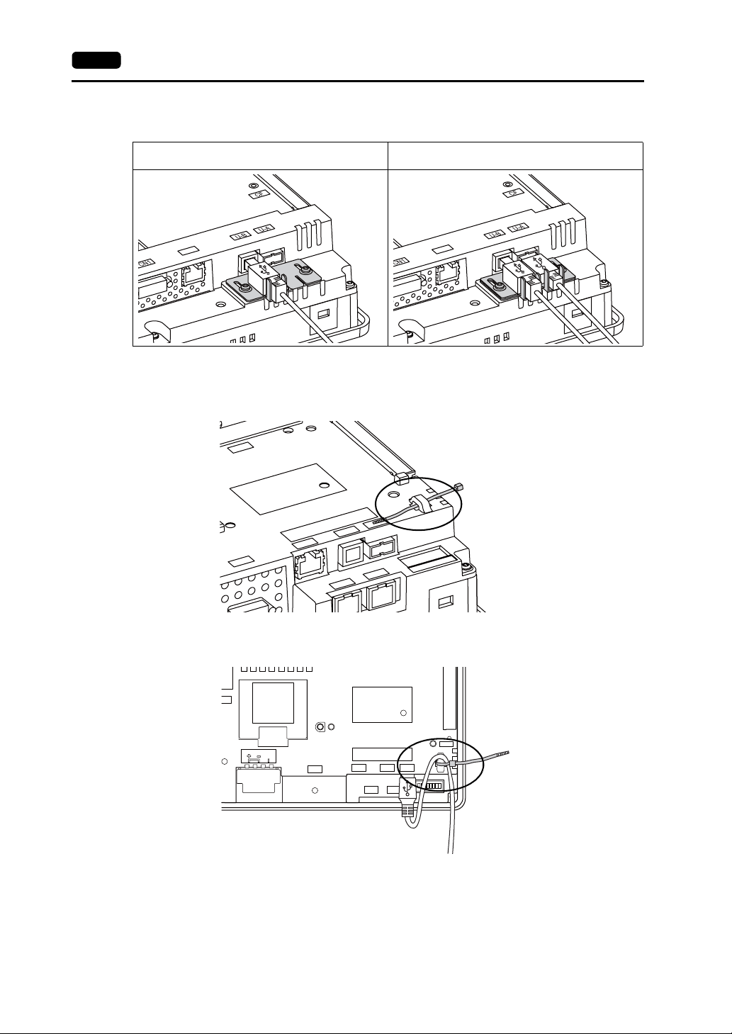
2-30 6. USB Connector
The following figure shows the case where only USB-B is used and the one where both USB-A
and B are used.
When only USB-B is used:
LAN
When both USB-A and USB - B ar e used
(two cables are used):
LAN
Securing USB Cable on V812 / V810 (Hardware version : “j” or later), V808
1. Having a cable tie
Draw a cable tie through the hole as shown in the figure below.
CN7
U-A
MJ1
U-B
MJ2
LAN
CN1
2. Inserting and securing a USB cable
Insert a USB cable and secure it using the cable tie.
N5
24VDC
FG
CN1
LAN
MJ1
RESET
U-B
U-A
MJ2
Page 56
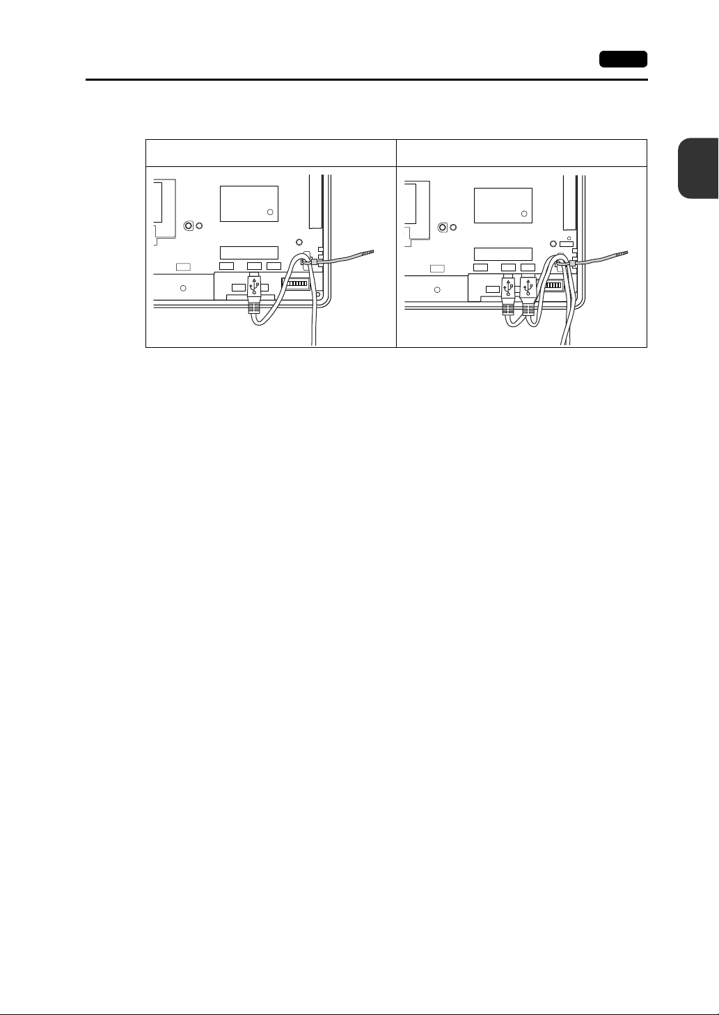
6. USB Connector 2-31
The following figure shows the case where only USB-B is used and the one where both USB-A
and B are used.
When only USB-B is used:
CN1
LAN
MJ1
When both USB-A and USB-B are used
(two cables are used):
2
Specifications
RESET
U-B
MJ2
U-A
CN1
LAN
MJ1
U-B
U-A
MJ2
Page 57

2-32 7. LAN Connector (LAN)
7. LAN Connector (LAN)
LAN Connector
An Ethernet-ready controller can be connected via a LAN connector.
The LAN connector supports 100BASE-TX/10BASE-T.
• For V812/V810 • For V808
Bottom View Bottom View
MJ1 (or MJ2) and LAN connector are 8-pin modular jacks.
CAUTION
The LAN connector pins correspond to signals as given below.
Specification: IEEE802.3 (u) compliant, supporting UDP and TCP/IP
Check the indication on the unit and insert a cable into the correct position.
Do not connect any over voltage peripheral device to the LAN connector.
LAN Pin No. Signal Contents
8 76 5 4321
1 TX+ Ethernet send signal (+)
2TX− Ethernet send signal (−)
3 RX+ Ethernet receive signal (+)
4 NC Not used
5 NC Not used
6RX− Ethernet receive signal (−)
7 NC Not used
8 NC Not used
Page 58

Wiring
7. LAN Connector (LAN) 2-33
CAUTION
Distance between the node and the HUB: 100 m maximum
Maximum network nodes: 100
When using the LAN port, keep the LAN cable away from the power supply cable as
much as possible.
UTP cable
Straight cable
PLC
Cable Connection Diagram
Straight cable
(with hub)
RJ-45 8Pin
1
2
3
6
4
5
7
8
* Unshielded twist-pair cable * Unshielded twist-pair cable
HUB
CU-03-3 LAN
V8
F 7F 6F 5F 4F 3F 2F 1
SYSTEM
SYSTEM
RJ-45 8Pin
1
2
3
6
4
5
7
8
UTP cable
Straight or cross cable
(For more information, refer to the HUB specifications.)
V8i
Node
F 7F 6F 5F 4F 3F 2F 1
HUB
Node
Cross cable
(without hub)
RJ-45 8Pin RJ-45 8Pin
1
2
3
6
4
5
7
8
2
Specifications
3
6
1
2
4
5
7
8
Recommended Cable
Use a commercially available cable. Using a self-made cable may cause an error in network
connection.
Recommended cable: 100Ω, UTP (unshielded twist-pair) cable, category 5
Page 59

2-34 8. CF Card
8. CF Card
CF Card Connector
Screen data can be transferred and historical data and image data can be saved on the CF card.
The CF card interface is provided at the rear of the unit.
• For V812/V810 • For V808
Enlarged View
CF card interface cover
Rear View
CN5
MJ2
CN1
MJ1
Rear View
CN7
CN5
CF
LAN
U-AU-B
24VDC
FG
LAN
CN1
CF
CN7
U-B
U-A
MJ2
MJ1
* Hardware version “a” to “i” of
V812xS/V810xS/V810xT/V808xS
Enlarged View
LED
LED
CF card interface cover
LED
With the DIPSW2, the LED status when the CF card interface cover is opened can be set.
DIPSW2 LED Contents
OFF
Off
Lights up in red
ON Lights up in red Access to the CF card is possible at all times.
When the DIPSW2 is set to the ON position, access to the CF card is
CAUTION
possible whether the cover is opened or not. In case access to the CF card
is disabled because of damage of the CF card interface cover, set the
DIPSW2 to the ON position. Normally keep it in the OFF position.
The power is not supplied to the CF card.
The CF card can be removed.
The power is supplied to the CF card.
At the completion of access, the LED goes off.
Page 60

Notes on Handling the CF Card
8. CF Card 2-35
1. The V8 series can recognize a CF card in the file system of FAT or FAT32.
2. The LED lamp on the CF card interface cover illuminates in red when the power is supplied to the
CF card. Do not insert or remove the CF card while the LED lamp is illuminating. Doing so may
destroy data on the CF card. Check that the LED lamp has gone off before inserting or removing
the CF card.
* DIPSW2: OFF (R efer to “LED” on page 2-34.)
3. Do not turn the main unit off during access to the CF card.
4. Make a backup copy of the CF card at regular intervals.
5. If a disk error occurs and data read/write operation is disabled, perform a scan disk on Windows
and try to restore the disk.
If not restored, format the CF card. Note that data on the CF card will be completely deleted by
formatting. (For information on scan disk and Windows operations, refer to the manual for
Windows.)
6. The number of writing times per CF card is limited (approx. 300,000 times). Consequently,
frequent writing at short intervals may shorten service life of the CF card. When using a CF card to
save sampling data, be aware of the sampling time. Also, avoid repeated writing using a CYCLE
macro command.
7. When using the CF card of a large capacity (2G or above), it may take long time for the V8
recognize the CF card. Do not insert or remove the CF card in a short time.
CF Card Insertion/Removal Procedure
1. Open the CF card interface cover.
2. Insert the card securely into the interface with the card backside outwards viewed from the side of
the unit as shown below.
2
Specifications
CAUTION
Eject button
Insert the CF card into the V8 unit in the correct orientation. Failure to do so may
damage the CF card or the socket at the unit.
* Hardware version “a” to “i” of
V812xS/V810xS/V810xT/V808xS
LED
Backside
Eject button
Backside
3. Close the CF card interface cover. The LED lamp lights up in red.
4. To remove the card, open the CF card interface cover first. When the LED lamp has gone off,
press the eject button. The card pops out.
LED
Page 61

2-36 8. CF Card
Please use this page freely.
Page 62

3
1. Mounting Procedure
2. Power Supply Cable Connection
Installation
Page 63

Page 64

1. Mounting Procedure
Mounting Procedure
1. Insert the V8 unit into the mounting panel (max. thick: 5 mm).
1. Mounting Procedure 3-1
Panel cut-out dimensions
X
Model
V812 / V812i
V810 / V810i
V808 / V808i
313.0
289.0
220.5
X
+0.5
-0
+0.5
-0
+0.5
-0
X
246.2
216.2
165.5
Y
+0.5
-0
+0.5
-0
+0.5
-0
Unit: mm
Y
Y
2. Insert four fixtures attached to the V8 series into the mounting holes, and tighten them with the
tightening screws.
Tightening torque: 0.5 to 0.7 N•m
Fixture dimensions
(Unit: mm)
CN7
CF
RESET
U-A
U-B
LAN
CN1
18.0
10.5
17.8
* When the V8 unit is attached to the
mounting panel, the fixtures and frame
grounds (FG) are connected. To prevent
static electricity, be sure to connect the
mounting panel to the frame ground.
CN5
MJ2
MJ1
3
Installation
3. Mount the gasket so that it will be sandwiched securely between the V8 unit and the mounting
panel.
Page 65

3-2 1. Mounting Procedure
Mounting Angle
Install the unit within the angle of 15° to 135° as shown on the right.
Type Optional Unit Communication Unit Mounting Angle
V812xS
V810xS
V810xT
V808xS
V810xC
V808xC
None
GU-xx
90°
135°
D
i
s
p
l
a
y
45°
y
a
l
p
s
i
D
15°
0
None
CU-xx
None
CU-xx
None
CU-02
CU-06 (Hardware version “d” and earlier)
CU-00
-
CU-01
CU-03-3
CU-04
CU-06 (Hardware version “e” and later)
CU-07 (I/F driver under development)
CU-08
15° to 135°
45° to 135°
15° to 135°
Page 66

2. Power Supply Cable Connection 3-3
2. Power Supply Cable Connection
DANGER
Electric shock hazard
Shut the power off before connecting the power supply cable.
Power Supply Cable Connection
Connect the power supply cable to the terminal on the backside of the unit.
• For V812/V810 • For V808
LAN
CN1
FG
Grounding
CN7
CF
U-AU-B
DC24V
24V DC
Power
supply
CN5
MJ2
MJ1
AC100V-240V
LN
Power
supply
FG
Grounding
3
Installation
CF
CN7
CN5
24VDC
FG
LAN
U-B
DC24V
24V DC
Power
supply
MJ1
U-A
MJ2
FG
Grounding
CN1
• Tighten terminal screws on the power supply terminal block with the following torque.
Use a power supply cable within the range shown below.
8 mm or
less
7.1 mm
or less
Terminal Screw
Crimp-style Terminal
3.7 mm
3.7 mm
8 mm or
less
7.1 mm or
less
Power Cable
φ3.7 mm
φ3.7 mm
Model
V812
V810
Screw
Size
Tightening
Torque
M3.5 0.8 N•m AWG16 - 18
V808 M3.5 0.8 N•m AWG14 - 16
Page 67

3-4 2. Power Supply Cable Connection
Notes on the Power Supply:
• The power source must be within the allowable voltage fluctuation.
• Use a power source with low noise between the cables or between the ground and the cable.
• Use as thick a power supply cable as possible to minimize drop in voltage.
• Keep power supply cables away from high-voltage, large-current carrying cables.
Notes on Usage of 100 - 240 VAC Specifications
• Generally, an isolating transformer improves noise resistance. However, if the display unit is far
away from the secondary port of the transformer and noise gets mixed in, an isolating transformer
becomes unnecessary.
• If any power voltage fluctuation caused by noise is expected, it is recommended that a voltage
stabilizer (effective in noise resistance) be used.
Power supply
Grounding
CAUTION
• An independent earth pole must be used for MONITOUCH.
• Use a cable which has a nominal cross section of more than 2 mm
• Set the grounding point near MONITOUCH to shorten the distance of grounding cables.
Insulation transformer or
stabilized transformer
2
1.25 mm
Twist the cables.
To the V8 unit
Be sure to establish a ground of the V8 series.
(The level of grounding resistance should be less than 100Ω.)
2
for grounding.
V8 unit
Other
equipment
V8 unit
Other
equipment
V8 unit
Other
equipment
* When the V8 unit is attached to the mounting panel, the fixtures and frame grounds (FG) are
connected. To detach the FG terminal from the ground, attach the insulating sheet to the
fixtures and the mounting panel for insulation.
Page 68

4
1. Coin-type Lithium Battery (V7-BT)
2. DIP Switches
3. Function Switches
Instructions
Page 69

Page 70

1. Coin-type Lithium Battery (V7-BT) 4-1
1. Coin-type Lithium Battery (V7-BT)
MONITOUCH is delivered without inserting the battery connector in the battery holder
CAUTION
Battery Usage
The battery is used for the user memory area (non-volatile memory $L and $LD, storing sampling data,
etc.) in SRAM, or backup battery for the built-in clock.
Battery Mounting Procedure
on the back of the unit.
Be sure to set the battery when using the calendar function or SRAM.
Without a battery, the contents in the SRAM or calendar will not be retained.
4
Instructions
DANGER
Electric shock hazard
Steps 2 to 5 must be performed when the power to the V8 series is turned off.
1. Turn the unit off.
2. Open the battery holder cover in the direction of the arrow as shown in the left illustration below.
Rear View
CN5
MJ2
MJ1
CN7
CF
LAN
CN1
RESET
U-AU-B
3. Check that the battery is securely attached to the backside of the cover, and connect the battery
connector.
Coin-type lithium battery
Battery cable
(Upon delivery)
Battery connector
Page 71

4-2 1. Coin-type Lithium Battery (V7-BT)
4. Close the battery holder cover.
5. Enter a date five years from now for “Battery replacement” on the sticker on the battery holder.
Write down the date five years from now.
6. Turn the V8 unit off.
When no battery is set, the message “Battery not set” is displayed, and when the battery voltage
has dropped, the message “Brownout Battery” is displayed at the bottom center of the Main Menu
screen.
Main Menu screen when the battery is not connected
Do not Replace Battery in a
Hazardous Location. Replacement
of Battery shall be done by an
expert only. See operating or
maintenance instruction for
type of battery to be used.
Battery replacement.
Battery not set
SYSTEM
F 1
F 2
F 3
F 4
F 5
F 6
F 7
The message
“Battery not set”
Battery Voltage Drop Detection
The battery status is output to the internal memory $s167 of the V8 series.
When the battery voltage is lowered, the message “Brownout Battery” is displayed at the bottom
center on the Main Menu screen.
If the battery voltage drops (4th bit is set) before five years has elapsed, replace the battery
immediately.
MSB LSB
15 14 13 12 11 10 09 08 07 06 05 04 03 02 01 00
$s167
0000000000 0
System reserved (Setting: 0)
000
0: Battery OK.
1: Battery voltage drop
2: No battery
Page 72

Battery Replacement
Replacement batteries are available from Hakko Electronics.
Name Model Contents
Battery for
replacement
V7-BT
Safety Instructions on Handling the Battery
Lithium batteries contain combustible material such as lithium or organic solvent. Mishandling may
cause heat, explosion or ignition resulting in fire or injury. To prevent accidents, pay attention to the
following cautions when handling the lithium battery.
• Be sure to discharge static electricity from your body before battery replacement.
• Use the battery “V7-BT” (replacement battery) for replacement.
• Rough handling of the battery may cause a fire or chemical burn hazard.
• Do not disassemble, incinerate or heat the battery.
CAUTION
• Observe local and governmental regulations when disposing of waste batteries.
• Keep batteries out of reach of children. (If swallowed, immediately consult a doctor.)
• Never re-charge the battery.
• When the battery leaks or smells, the leaking battery electrolyte may catch fire.
Keep from heat or flame.
SRAM Area Backup Procedure
Replace the battery “V7-BT” within three minutes after the unit is turned off.
If it is not possible to replace within three minutes, use the V-SFT-5 editor or a CF card and make a
backup copy of data in the SRAM.
When Using the V-SFT-5 Editor:
1) Connecting a cable
Connect the V8 unit and the computer using the transfer cable (“V-CP”, USB cable,
Ethernet cable)
2) Starting the V-SFT-5 editor
Start the V-SFT-5 editor on the computer.
3) Displaying the [Transfer] dialog
Click the [Transfer] icon. The [Transfer] dialog is displayed.
4) Selecting data to be transferred
Select [Display] for [Transfer Device], and [SRAM Data] for [Transfer Data].
Do not check [Use Simulator].
5) Starting SRAM data transfer
Click the [PC <−] button under [Transfer]. Data transfer from the SRAM is started.
6) Saving the SRAM data
When the SRAM data has been transferred, the [Save As] dialog is displayed on the
computer. Save the data as a backup copy. The extension is “∗.RAM”.
* To transfer the “∗.RAM” data saved as a backup to the V8, click the [PC −>] button under
[Transfer] in step 5).
When Using a CF Card:
For the backup procedure with a CF card, refer to “Saving Backup Copies of SRAM” (page
5-24).
• Coin-type lithium primary cell 1 pce.
• Cautions sticker 1 pce.
1. Coin-type Lithium Battery (V7-BT) 4-3
4
Instructions
Page 73

4-4 1. Coin-type Lithium Battery (V7-BT)
Battery Replacement Procedure
1. Turning the power of the V8 unit off
Turn the power of the V8 unit off, and open the battery holder. The battery in the socket will come
into view.
2. Battery removal
Unplug the battery connector. Slide the battery toward the
direction shown in the figure on the right, and remove the battery
from the socket.
3. New battery installation
Fit the battery into the socket in such a manner that the red
cable side of the new battery faces the board and the cable
is on the left of the battery . Before fitting the battery into the
Socket
Battery holder
socket, slide it toward the direction shown in the figure on
the right.
4. Battery connector plug-in
Plug in the battery connector and close the battery holder
cover.
5. Entering an expiry date of the battery
Battery connector
Remove the existing caution sticker. Enter a date five
years from now for “Battery replacement” as an expiry date on the new caution sticker, and attach
it to the battery holder.
6. Turning the power of the V8 unit on
Turn the power of the V8 unit on and check that the battery is correctly set on the Main Menu
screen.
7. Backup data transfer
If the backup data “∗.RAM” has been made, transfer it to the V8 series.
Printed
circuit
board
Page 74
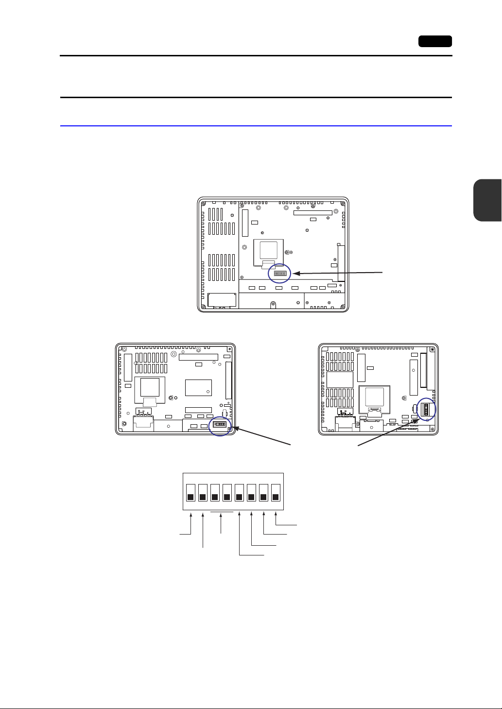
2. DIP Switches
DIP Switch (DIPSW) Setting
The V8 series is equipped with eight (1 to 8) DIP switches. When setting the DIP switch, turn the
power off.
Upon delivery, all the DIP switches are set to OFF.
For V812xS / V810xS / V810xT / V810xC
Rear View
CN5
2. DIP Switches 4-5
4
CN7
Instructions
For V808xS
Rear View
CN5
24VDC
FG
CF auto-loading
CF card interface cover
access control
CN7
LAN
CN1
MJ1
CF
RESET
U-B
U-A
MJ2
ON
12345678
Not used
CF
MJ2
MJ1
LAN
CN1
RESET
U-AU-B
For V808xC
Rear View
CN5
24VDC
FG
CN1
DIP switch
MJ2 (modular jack 2) terminal resistance
CN1 +RD/-RD terminating resistance at pins 1 and 2
MJ1 (modular jack 1) terminal resistance
CN1 +SD/-SD terminating resistance at pins 3 and 4
DIP switch
U-B
LAN
MJ1
CF
U-A
MJ2
Page 75

4-6 2. DIP Switches
DIPSW1* (CF Auto Loading)
Set the DIPSW1 to the ON position when auto-loading a screen data file saved on a CF card.
Procedure
1. Have a CF card.
Have a CF card to which the screen data is loaded using the V-SFT-5 editor. (For the loading
procedure, refer to the V8 Series Reference Manual.)
2. Insert a CF card.
Turn the power of the V8 unit off, and set the DIPSW1 to the ON position. Open the CF card
interface cover, and insert a CF card.
3. Auto-loading starts.
Turn the power of V8 unit on. The screen data is automatically loaded into the FLASH memory of
MONITOUCH.
* Be sure to set the DIPSW1 to the OFF position if you do not use CF auto-loading fun ct i on.
DIPSW2 (CF Card Interface Cover Access Control)
When the DIPSW2 is set to the ON position, access to the CF card is possible whether
CAUTION
the cover is opened or not. In case access to the CF card is disabled because of
damage of the CF card interface cover, set the DIPSW2 to the ON position. Normally
keep it in the OFF position.
With the DIPSW2, the LED status when the CF card interface cover is opened can be set.
DIPSW2 LED Contents
OFF
Not lit
Lights up in red
ON Lights up in red Access to the CF card is possible at all times.
Access to the CF card is not performed.
CF card can be removed.
Accessing the CF card
After the access is finished, the LED goes off.
DIPSW3, 4 (Not Used)
Set the DIPSW3 and 4 to OFF.
DIPSW5, 6, 7, 8 (Terminating Resistance Setting)
CAUTION
• When connecting a controller at CN1 via RS-422/485 (2-wire connection), set the DIPSW7 to the
ON position.
• When connecting a controller at CN1 via RS-422/485 (4-wire connection), set the DIPSW5 and 7
to the ON position.
• For the following connections at modular jack 1 or 2, set the DIPSW6 or 8 to the ON position.
When connecting a controller at CN1 via RS-232C, set the DIPSW5 and 7 to the OFF
position.
- Master station for multi-link 2 connection
- Connection with a controller (PLC, temperature controller, etc.) via RS-485
- Connection with the card recorder “CREC” (optional)
- Connection with the serial extension I/O “V-I/O” (optional)
- Connection to the V8 series at the termination of V-link connection via RS-485
Page 76

3. Function Switches
Types
There are eight function switches provided.
[SYSTEM], [F1], [F2], [F3], [F4], [F5], [F6], [F7]
Function of Switches
3. Function Switches 4-7
[SYSTEM] Switch
The [SYSTEM] switch works in “alternate” operations.
When the [SYSTEM] switch is pressed once, the switch menu is displayed at the left side of the
function switches [F1] to [F7] as shown in the figure below. Each function switch corresponds to the
item displayed in the switch menu.
Works as user-defined
function switches.
* If the switch menu is not displayed with the [SYSTEM] switch pre ssed, th e [SYSTEM] switch is disabl ed. To
enable the [SYSTEM] switch, keep pressing the [F7] switch for the time specified for [Change-over Time]
(max. 30 seconds) with the [SYSTEM] switch held down. [Change-over Ti me] is set on the editor.
When the switch menu is not displayed: When the switch menu is displayed:
S
Y
S
T
E
M
SYSTEM
F 1
F 2
F 3
F 4
F 5
F 6
F 7
Works as switches that
correspond to the item in
the switch menu.
SYSTEM
M
O
F 1
D
E
BR
F 2
BR
F 3
BR
F 4
B
A
C
F 5
K
L
T
F 6
F 7
4
Instructions
Page 77

4-8 3. Function Switches
[F1] to [F5] Switch Functions with Switch Menu Displayed
Functions Specifications
*1
*1
Mode
selection
Brightness
Backlight
control
*3
Selects the operation mode between STOP ↔ RUN.
Bright
Medium
Dark
Always ON -
Auto 1
Auto 2
Auto 3
• The [F5] switch turns the backlight off.
• This is valid when the backlight control bit (bit 11) in the read
area “n + 1” in the system memory is reset (OFF: 0).
• Manual
The [F5] switch turns the backlight off. To turn it on, press
somewhere on the screen or a function switch.
Manual
Manual 2
• Manual 2
The [F5] switch turns the backlight on and off.
• [Backlight Power ON Time Control] that determines the
backlight status at power-up becomes valid.
When the power is turned on:
ON → Backlight ON
OFF → Backlight OFF
F1
F2
F3
F4
F5
F6 -
F7 -
*2
S
Y
S
T
E
M
SYSTEM
M
O
F 1
D
E
BR
F 2
BR
F 3
BR
F 4
B
A
C
F 5
K
L
T
F 6
F 7
*1 When a medium or dark brightness is set, the backlight service life may become shorter.
*2 If the mode cannot be changed between STOP and RUN using the [MODE] switch, the [F1] (MODE) switch is
disabled. To enable the [F1] (MODE) switch, keep pressing the [F7] switch for the time specified for
[Change-over Time] (max. 30 seconds) with the [F1] switch held down while the switch menu is displayed by
pressing the [SYSTEM] switch. [Change-over Time] is set on the edi tor.
*3 The backlight can be controlled by the setting in the [Backlight] tab wind ow that is di splayed by selecting
[System Setting]
→ [Unit Setting] → [Backlight] on the V - SFT-5 editor.
User-defined Settings for Function Switches [F1] to [F5]
When the V8 series is in the RUN mode and the switch menu by the [SYSTEM] switch is not
displayed, the function switches can be defined by the user.
User-defined function switches should be set on the V-SFT-5 editor.
- Settings for each screen
[Screen Setting] → [Local Function Switch Setting] → [Local Function Switch Setting] dialog
- Setting for all screens
[System Setting] → [Global Function Switch Setting] → [Global Function Switch Setting] dialog
* If the switch menu is not displayed by the [SYSTEM] switch on the Main Menu scr een, no function is
specified for each function switch.
Page 78

5
1. Before Operation
2. Main Menu Screen
MONITOUCH
Operations
Page 79

Page 80

1. Before Operation
Procedure before Operation
1. Mount the V8 series on the mounting panel, install it and carry out wiring.
For more information, refer to “Chapter 3”.
2. Install peripheral devices, such as PLCs or temperature controllers, and carry out wiring.
For information on precautions, refer to the V8 Series Connection Manual separately provided.
3. Turn the power of the V8 series on.
When turning the power on for the first time:
1. Before Operation 5-1
Other cases:
5
SYSTEM
F 1
F 2
F 3
F 4
F 5
F 6
F 7
SYSTEM
F 1
F 2
F 3
F 4
F 5
F 6
F 7
MONITOUCH Operations
4. Transfer the created screen data.
• When turning the power on for the first time:
For details, refer to “Transferring Screen Data to MONITOUCH for the First Time” (page 5-2).
• Other cases:
For the procedure to change screen data with another, refer to the V8 Series Operation
Manual.
5. Start MONITOUCH operation. To change to the RUN mode, refer to “Main Menu Screen” (page
5-3).
When the connection with controllers has been established, the RUN screen is displayed.
* If MONITOUCH does not operate normally and shows an error message, eliminate the cause
by referring to “Chapter 6” or the V8 Series Reference Manual.
Page 81

5-2 1. Before Operation
Transferring Screen Data to MONITOUCH for the First Time
There are five methods for transferring screen data for the first time.
Initial screen displayed when the power is turned on for the first time
CF
MJ1
USB-B
LAN
MJ1
F 1
F 2
F 3
F 4
F 5
F 6
F 7
IP address setting
for the V8
Displays the Card
Transfer screen.
SYSTEM
Memory card
V-CP
USB
Ethernet
CREC
Displays communication status between the V8 and the computer.
1) Serial transfer
Connect the screen data transfer cable “V-CP” to the modular jack 1 on the V8 series, and
transfer screen data from the computer.
2) Transfer via USB
Connect the USB cable to the USB slave port (USB-B) on the V8 series, and transfer screen
data from the computer.
3) Transfer using a card
A CF card or card recorder “CREC” (optional) and memory card
are required.
Load screen data from the computer to the card in advance. Press
the [CF Card (English)] switch on the initial screen. The Card
Transfer screen is displayed and data transfer is enabled.
4) Transfer using a CF card (auto-loading)
Load screen data from the computer to the card in advance. When the power of MONITOUCH
is turned on, screen data transfer is automatically started.
5) Transfer via Ethernet
Connect an Ethernet cable to the LAN port on the V8 series, and
transfer screen data from the computer.
Pressing the [IP Address (English)] switch on the initial screen
brings up the Ethernet screen on which you can set the IP address for the V8 series.
When the screen data has been transferred, the following screen is brought up. For details, refer
to “Main Menu Screen” (page 5-3).
Main Menu screen after screen data is transferred
SYSTEM
F 1
F 2
F 3
F 4
F 5
F 6
F 7
Page 82

2. Main Menu Screen
Displaying the Main Menu Screen
To bring up the Main Menu screen in the RUN mode, press the [SYSTEM] switch and then the [F1]
switch (*2) while the switch menu is displayed (*1).
2. Main Menu Screen 5-3
Main Menu screen
SYSTEM
Switch menu
*1 If the switch menu is not displayed with the [SYSTEM] switch pressed, the [SYSTEM] switch is disabled. To
*2 If the Main Menu screen is not brought up with the [F1] switch pressed , the [F1] (= [MODE]) switch is disable d.
F 1
F 2
F 3
F 4
F 5
F 6
F 7
enable the [SYSTEM] switch, keep pressing the [F7] switch for the time specified for [Change-over T i me] (max.
30 seconds) with the [SYSTEM] switch held down. [Change-over Time] is set on the editor.
To enable the [F1] (= [MODE]) switch, keep pressing the [F7] switch for the time specified for [Cha nge-over
Time] (max. 30 seconds) with the [F1] switch held down while the switch menu is displayed by pressing the
[SYSTEM] switch. [Change-over Time] is set on the editor.
Main Menu Screen
The Main Menu screen indicates the V8 series model, system information, and screen data
information.
Also, it works as the system screen when the screen data is transferred between a computer and the
V8 series. To transfer screen data from the computer to the V8 series through serial communication,
display this Main Menu screen. (However, if [No connection] is selected for [Modular Jack1], it is not
necessary to bring up the this screen.)
SYSTEM
F 1
F 2
F 3
F 4
F 5
F 6
F 7
SYSTEM
F 1
F 2
F 3
F 4
F 5
F 6
F 7
5
MONITOUCH Operations
Main Menu drop-down window
Screen data file comment, total amount
of memory occupied by the screen data
System program version
Font version
Ethernet information
Port used for screen data transfe r
* For more information on the hardware version, refer to page 7-3.
V8-series model
“*” : Hardware version “j” or later
None : Hardware version “a” to “i”
SYSTEM
F 1
F 2
F 3
F 4
F 5
F 6
F 7
Clock
Controller and
version of the I/F
driver specified for
the screen data file
Page 83

5-4 2. Main Menu Screen
[Main Menu] Switch
Pressing the [Main Menu] switch brings up the following drop-down window.
Main Menu screen Main Menu drop-down window
Main Menu Screen Composition
SYSTEM
F 1
F 2
F 3
F 4
F 5
F 6
F 7
The Main Menu screen is configured as shown below:
Main Menu
Screen
[Main Menu]
switch
RUN screen (refer to page 5-5.)
Language screen (refer to page 5-5.)
Comm. Parameter screen (refer to page 5-6.)
Ethernet screen (refer to page 5-7.)
SRAM/Clock screen (refer to page 5-11.)
Extension Program Info. screen (refer to page 5-14.)
Card Transfer screen (refer to page 5-15 .)
Card Recorder Menu screen (refer to page 5-28.)
RGB Adjustment screen (refer to page 5-31.)
I/O Test screen (refer to page 5-34.)
Print Test screen (refer to page 5-40.)
Touch switch test screen (refer to page 5-42.)
Keyboard screen (refer to page 5-44.)
For details on the simulator , re fer to the V8 Seri es Opera tion
Manual separately provided.
For details on the extended setting, refer to the V8 Series
Reference Additional Functions provided.
Extended Function Setting screen
Displayed by pressing the [Editor: MJ1] switch at the bottom left on the
Main Menu screen and the [F5] function switch at one time. For more
information, refer to “Extended Function Setting” (page 5-45).
Page 84

1. RUN
Pressing the [RUN] switch on the Main Menu drop-down window switches the screen to the RUN
mode.
Main Menu drop-down window
2. Main Menu Screen 5-5
RUN screen
SYSTEM
F 1
F 2
F 3
F 4
F 5
F 6
F 7
5
MONITOUCH Operations
2. Langu age Selection
Pressing the [Language] switch on the Main Menu drop-down window brings up the Language
Selection screen.
Languages (*) selected in the [Font Setting] dialog of the V-SFT-5 editor are displayed on the
Language Selection screen that is used for selecting an interface language for the Main Menu screen.
Main Menu drop-down window
Language Selection screen
SYSTEM
F 1
F 2
F 3
F 4
F 5
F 6
F 7
* The interface language for the Main Menu screen can be selected fro m English, Japane se, Chinese (simplif ied),
Chinese (traditional) or Korean. English is always displayed.
Page 85

5-6 2. Main Menu Screen
3. Communication Parameter
Pressing the [Comm. Parameter] switch on the Main Menu drop-down window brings up the Comm.
Param. screen.
Communication parameters of PLC1 to PLC8 that are set on the V-SFT-5 editor can be checked on
this screen.
Main Menu drop-down window
Displays a specified
communication
parameter.
Comm. Param. screen
SYSTEM
Moves back to the
Main Menu screen.
F 1
F 2
F 3
F 4
F 5
F 6
F 7
Changes the display
of the setting from
PLC1 to PLC8.
Page 86

4. Ethernet
Pressing the [Ethernet] switch on the Main Menu drop-down window brings up the Ethernet screen.
This screen is used for setting an IP address for the V8 unit.
Main Menu drop-down window
2. Main Menu Screen 5-7
5
MONITOUCH Operations
Ethernet screen
Selects [Built-in LAN]
or [Extended LAN].
Selects [IP Address
Setting] or [Select IP
Address from Network
*2
Table].
Indicates whether the LAN port works correctly
with an Ethernet cable inserted.
*1
Normal: Connect (white)
Abnormal: Disconnect (gray)
*1 This is valid only when the Ethernet unit CU-03-3 is installed.
*2 Refer to the V8 Series Connection Manual.
Moves back to the
SYSTEM
F 1
F 2
F 3
F 4
F 5
F 6
F 7
Main Menu screen
or the initial screen.
Displays the keypad
for IP address
setting.
When making the setting, press the [Setting
Finished] switch to determine the setting. The
Main Menu screen is displayed.
Page 87

5-8 2. Main Menu Screen
4-1. IP Address Setting of the V8 Series
When using Ethernet communications, you need to set the IP address of the V8 unit. Set the IP
address either on the V8 unit or for screen data using the V-SFT editor.
Setting on the V8 Unit
1. Press the [Ethernet] switch on the Main Menu drop-down window to display the Ethernet screen.
2. Select [Built-in LAN] or [Extended LAN] by pressing the switch to specify the port for setting.
3. Press the [EDIT] switch and set each item.
Before change
It is not used when the gateway or the subnet mask is zero.
4. Press the [Setting Finished] switch to determine the IP address. Check the IP address displayed
at “Ethernet Information” on the Main Menu screen.
Determine the IP address setting.
Change the IP address using the keypad.
Page 88

Setting using the V-SFT editor
1. Select [System Setting] → [Ethernet Communication] → [Local Port IP Address] on the V-SFT
editor. The [IP Address Setting] dialog is displayed.
2. Specify the IP address.
When specifying an IP address for the built-in LAN port, select [IP Address Setting]. Alternatively,
when specifying an IP address for the Ethernet unit, select [IP Address Setting (extended)].
2. Main Menu Screen 5-9
For the built-in LAN port
For the Ethernet unit
3. Check the [ Set IP] check box and set each item.
Select IP Address from
Network Table
IP Address
Send Timeout Specify the timeout time to send the EREAD/EWRITE command.
Retrials
Memory Protect
*
Default Gateway
Subnet Mask
Port No.
Internal Memory
Memory Card Memory
*
*
*
This is valid when the IP address of the V8 has been registered in the
network table. Select a network table number from 0 to 99 to set the IP
address.
Set the IP address for the V8.
Set the default gateway.
Set the subnet mask.
When this box is not checked, the subnet mask is automatically assi gned
based on the bits at the extreme left of the IP address.
Example:
When IP address is “172.16.200.185”, “255.255.0.0” is set.
When IP address is “192.168.1.185”, “255.255.255.0” is set.
Set a port number from 1024 to 65535 other than 8001.
0 to 255
Set the number of retrials to be performed when a time-out occurs.
Check either check box to write-protect the memory from computers or
other stations.
5
MONITOUCH Operations
* For more information on setting items, refer to page 5-10.
4. Click [OK].
5. Transfer the screen data to the V8 unit. Check the IP address displayed at “Ethernet Information”
on the Main Menu screen.
Page 89

5-10 2. Main Menu Screen
IP Address
This is an address that is used for recognizing each node on the Ethernet and should be unique.
The IP address is 32-bit data which consists of the network address and th e host address and can be classified
into A to C depending on the network size.
Class A
Class B
Class C
<Notation>
A string of 32-bit data is divided into four, and each segment delimited with a period is in decimal notatio n.
Example: The IP address in class C shown below is represented as “192.128.1.50”.
11000000 10000000 00000001 00110010
<Unusable IP addresses>
• “0” is specified for one byte at the extreme left. Example: 0.x.x.x
• “127” is specified for one byte at the extreme left (loop back address). Example: 127.x.x.x
• “224” or more is specified for one byte at the extreme left (for multi-cast or experiment). Example: 224.x.x.x
• The host address consists of only “0” or “255” (broadcast address). Example: 128.0.255.255, 192.168.1.0
Port No.
Multiple applications are running on each node, and communicatio ns are carried out for each application between
the nodes. Consequently , it is necessary to have a means to identify the application that data should be
transferred to. The port number works as this identifier. Each port number is 16-bit data (from 0 to 65535).
The V8 series uses the port for screen data transfer (8001), PLC communication (as desired), and the simulator
(8020). Set a unique number in the range of 1024 to 65535. For a PLC or a computer, set the port number in the
range of 256 to 65535. It is recommended to set a greater number.
0
10
110
Network
address (7)
Network address (14) Host address (16)
Network address (14)
Host address (24)
Host address (8)
Default Gateway
A gateway and a router are used for communication between different networks.
The IP address of the gateway (router) should be set to communicate with the node(s) on oth er network.
Subnet Mask
A subnet mask is used for dividing one network address into multiple networks (subnet).
The subnet is assigned by specifying a part of the host address in the IP address as a subnet address.
Class B
Subnet mask
<Unusable subnet masks>
• All bits are set to “0”. (0.0.0.0)
• All bits are set to “1”. (255.255.255.255)
10
Network address (14)
255. 255.
11111111
Network address Subnet address
11111111 11111111 00000000
Host address (16)
255.
Host address
0
Page 90

5. SRAM/Clock
Pressing the [SRAM/Clock] switch on the Main Menu drop-down window brings up the SRAM/Clock
screen.
This screen is used for correcting the built-in calendar (date and time), for formatting the SRAM area,
and for clearing learning/user phrase area in the Japanese FEP function.
Main Menu drop-down window
2. Main Menu Screen 5-11
5
MONITOUCH Operations
SRAM/Clock screen
Formats an SRAM
area.
Clears the learning/user
phrase area.
*1
*1 This option is displayed when [Use Japanese Conversion Function] in the [System Setting] menu is checked
on the V-SFT-5 editor. For the setting procedure, refer to the V8 Series Reference Manual.
*2 Be sure to set the battery. Without the battery, the contents in the SRAM or clock data will not be retained.
Moves back to the
SYSTEM
F 1
F 2
F 3
F 4
F 5
F 6
F 7
Main Menu screen.
Determines the
changed date and
time.
[←] / [→] switch:
moves the cursor.
[+] / [−] switch:
corrects the date and
time.
Displayed when the battery need to be replaced.
*2
Page 91

5-12 2. Main Menu Screen
5-1. Date and Time Adjustment
This screen is used for correcting the built-in clock of the V8 series.
To use the built-in clock of the V8 series, check [Use Built-in Clock] in the [SRAM/Clock Setting] dialog
that is displayed by selecting [System Setting] → [Unit Setting] → [SRAM/Clock] on the V-SFT -5 editor.
1. Move the cursor using the [←] and [→] switches. Correct the date and time using the [+] and [−]
switches.
2. Press the [Set] switch to determine the setting. The clock displayed at the top right is modified.
Before change
3. Pressing the [Return] switch displays the Main Menu screen again.
5-2. Formatting SRAM
An SRAM area can be formatted.
When the SRAM area is formatted, the contained data (historical data saved in SRAM, internal
memory $L, etc.) is cleared. Double-check before formatting the SRAM.
1. Press the [Format] switch and the [Execute] switch.
The SRAM area is formatted in the current screen data format. When formatting has been
completed, the message “∗∗Format Completed∗∗” is displayed.
Before formatting the SRAM area
After change
Format of the SRAM area completed
2. Pressing the [Return] switch displays the Main Menu screen again.
Page 92

2. Main Menu Screen 5-13
5-3. Japanese FEP Function Learning/User Phrase Area
The area used by the Japanese FEP function can be cleared.
When the learning/user phrase area is cleared, all of the registered data is deleted. Double-check
before clearing the area.
1. Press the [Clear] switch and the [Execute] switch. When the area has been completely cleared,
the message “∗∗Clear Completed∗∗” is displayed.
Format of the learning/user phrase area completedBefore clearing the learning/user phrase area
2. Pressing the [Return] switch displays the Main Menu screen again.
5
MONITOUCH Operations
Page 93

5-14 2. Main Menu Screen
6. Extension Program Information
Pressing the [Extension Program Info.] switch on the Main Menu drop-down window brings up the
Extension Program Info. screen. This screen is used for checking program versions of the ladder
transfer function, printer, Japanese FEP function, simulator, etc.
Main Menu drop-down window
Extension Program Info. screen
SYSTEM
Moves back to the
Main Menu screen.
F 1
F 2
F 3
F 4
F 5
F 6
F 7
Changes the page of
the extension program
information.
Displays the
extension program
information.
Page 94

7. Card Transfer
Pressing the [Card Menu] switch on the Main Menu drop-down window brings up the Card Transfer
screen.
This screen is used to transfer screen data between the V8 series and a CF card or a memory card.
Main Menu drop-down window
2. Main Menu Screen 5-15
5
MONITOUCH Operations
Card Transfer screen
SYSTEM
F 1
1.
2.
F 2
F 3
F 4
F 5
F 6
F 7
1. [CF Card inserted to] field
• [Built-in Socket]
Press this switch when using the built-in CF card connector on the V8 series.
• [USB Port]
Press this switch when using a CF card while a USB-CFREC (optional) is connected to the
USB-A (master port).
Moves back to the
Main Menu screen or
the initial screen.
4.
3.
Page 95

5-16 2. Main Menu Screen
2. [Data Selection] field
• [Screen Data]
Press this switch when transferring screen data using a CF card.
• [SRAM]
Press this switch when saving backup data in the SRAM memory or when uploading the
backup data from the CF card to the V8 series.
• [Ethernet Table]
Press this switch when transferring the Ethernet table (where an IP address for a PLC etc. is
registered) set on the V-SFT-5 editor using a CF card.
3. [Transfer Menu] field
• [Display <--- Card]
Transfers data from a CF card to the V8 series.
• [Display ---> Card]
Transfers data from the V8 series to a CF card.
• [Display <--> Card]
Compares data stored in the V8 series and that stored on the CF card.
• [Delete]
Deletes data on the CF card.
4. [Memory Card Recorder Menu] switch
Press this switch when connecting the card recorder “CREC” (optional) to the MJ port of the
V8 series and transferring screen data between the V8 series and a memory card.
For more information, refer to “Transferring Data to the Card Recorder” (page 5-28).
Page 96

7-1. Folder Configuration in the CF Card
CF Card Folder Configuration
Folders in the CF card are configured as shown below.
CF Card
DAT0000
Access folder
Folder Name
(Fixed)
BITMAP
CARD
DSP
FONT
HDCOPY
JPEG JPEG file
MEMO Memo pad data MEMxxxx.BIN
MSG Messages (Reduces the screen data capacity.)
OPELOG Operation log data OPELOG_xxyyzz.BIN
RECIPE Recipe data
SAMPLE Data of data logging and alarm history
SCRN
SNAP Video snapshot images VDxxxxx.JPG
*1
*2
Pattern (bitmap) data
(Reduces the screen data capacity.)
Recipe data using the V6-compatible memory
manager function
Screen data
Ethernet table
Gothic fonts or language data
(Reduces the screen data capacity.)
Hard copy image
(JPEG file format)
Screen
3D part
Windows font data
(Reduces the screen data capacity.)
Contents File Name
2. Main Menu Screen 5-17
BMPxxxx.BIN
MCMHEAD.BIN
MCMxxxx.BIN
DSP0000.BIN
xxxxxxxx.CSV
xxxxx.FTD
HDxxxx.JPG
HDxxxx.BIN
xxxxx.JPG
JPxxxxx.JPG
MSGxxyyy.BIN
MSGxxyyy.TXT
RECxxxx.CSV
xxxxxxxx.CSV
SMPxxxx.BIN
SMPxxxx.CSV
SCHEADER.BIN
SCxxxx.BIN
MCRxxxx.BIN
MSGxxxx.BIN
3Dxxxx.BIN
WFSxxxx.BIN
WFMxxxx.BIN
5
MONITOUCH Operations
SRAM Backup copy of data in the SRAM SRM0000.BIN
WAV
WEBSERV Files to be accessed from the Web browser
DSPDEF
TEST
BITMAP
CARD
Screen data auto upload folder
Folder Name
(Fixed)
DSP Stores screen data for auto-uploading. DSPDEF.BIN
*1
WAV files for sound output
(Reduces the screen data capacity.)
*3
Contents File Name
*1 This is an access folder set on the V-SFT-5 editor. Any folder name
within 32 one-byte characters can be given.
*2 These folders are automatically created when the access folder is
created. The folder name cannot be changed.
*3 The folder name for screen data auto uploading cannot be changed.
WAxxxx.WAV
xxxxxxxx.SHT
xxxxxxxx.HTM
xxxxxxxx.TXT
Page 97

5-18 2. Main Menu Screen
7-2. Transferring Screen Data
The procedure for transferring data when a CF card is inserted into the built-in socket of the V8 series
is described below.
1. Mounting the CF card
Open the CF card interface cover and insert a CF card into the connector at the rear of the V8 unit.
CF card
Backside
CF card cover
* Do not remove or insert the CF card in the later steps.
* Hardware version “a” to “i” of
V812xS/V810xS/V810xT/V808xS
CF card cover
CF card
Backside
2. Displaying the Card Transfer screen
Press the [Card Menu] switch on the Main Menu drop-down window displayed from the Main Menu
screen. The Card Transfer screen is displayed.
3. Selecting CF card location and data to be transferred
Select [Built-in Socket] in the [CF Card inserted to] field and [Screen Data] in the [Data Selection]
field.
Card Transfer screen
[CF Card inserted to] field
[Data Selection] field
SYSTEM
F 1
F 2
F 3
F 4
F 5
F 6
F 7
[Transfer Menu]
field
4. Transfer selection
• For details, refer to “When [Display <−− Card] Is Selected:” (page 5-19).
• For details, refer to “When [Display −−> Card] Is Selected:” (page 5-22).
• For details, refer to “When [Display <−−> Card] Is Selected:” (page 5-23).
Page 98

When [Display <−− Card] Is Selected:
1. When [Display <−− Card] is selected, the Card Transfer screen is displayed.
2. Main Menu Screen 5-19
Displays information of the
folder currently selected.
* The access folder name that is set for screen data is displayed as default. If there is no screen data in the
V8 series, “DAT0000” is displayed.
2. Checking the access folder
Check the contents of [Folder Name], [Rest Size], and [CF Card File Information]. If the correct
folder is selected, go to step 4. To change the folder, go to step 3.
3. Changing the access folder (file check in the folder)
To change the access folder to another, press the [Select Folder] switch.
The Select Folder screen is displayed. Select the desired folder and press the [OK] switch.
Card Transfer screen
Select Folder screen
Lights up during communication
with the CF card.
Folder name currently selected *
SYSTEM
F 1
F 2
F 3
F 4
F 5
F 6
F 7
Free space in the CF card
Used for checking or renaming
folder names. To step 3.
Starts tr ansfer from the card to the
unit ([Display <−− Card])
Moves back to the previous
screen.
5
MONITOUCH Operations
Moves the cursor.
Displays the contents
of the folder where the
cursor is placed.
SYSTEM
F 1
F 2
F 3
F 4
F 5
F 6
F 7
Displays folders in the CF card.
Determines the folder selection.
Page 99

5-20 2. Main Menu Screen
Pressing the [Folder Detail] switch displays the contents of the folder where the cursor is placed.
Moves the cursor.
The cursor is moved
by using the [↑] or [↓]
switch.
4. Data selection to be transferred
After selecting the folder, press the [Select Data] switch.
The [Data Selection] dialog is displayed, and the [Select Data] switch changes to [Start].
Select Folder screen Select th e data to be transferred.
SYSTEM
F 1
F 2
F 3
F 4
F 5
F 6
F 7
Moves back to the Select
Folder screen.
[Data Selection] dialog
[Start] switch
* To cancel the [Data Selection] dialog, press the [Return] switch.
5. Starting data transfer
Select the desired data, and press the [Start] switch. During data transfer, the [Start] switch
changes to [Transferring].
Starting data transfer Duri ng data transfer
Page 100

2. Main Menu Screen 5-21
6. Data transfer completed
When the data has been transferred successfully, the following message dialog is displayed.
Press the [OK] switch.
If the [Sys. Program] or [Select All] switch was selected on the [Data Selection] dialog, the Main
Menu screen is automatically displayed on completion of data transfer.
Data transfer completed
* If any other message is displayed, refer to “Message Dialog Displayed during Data Transfer
(between V8 and Card)” (page 5-30).
5
MONITOUCH Operations
 Loading...