

Page 1

Page 2

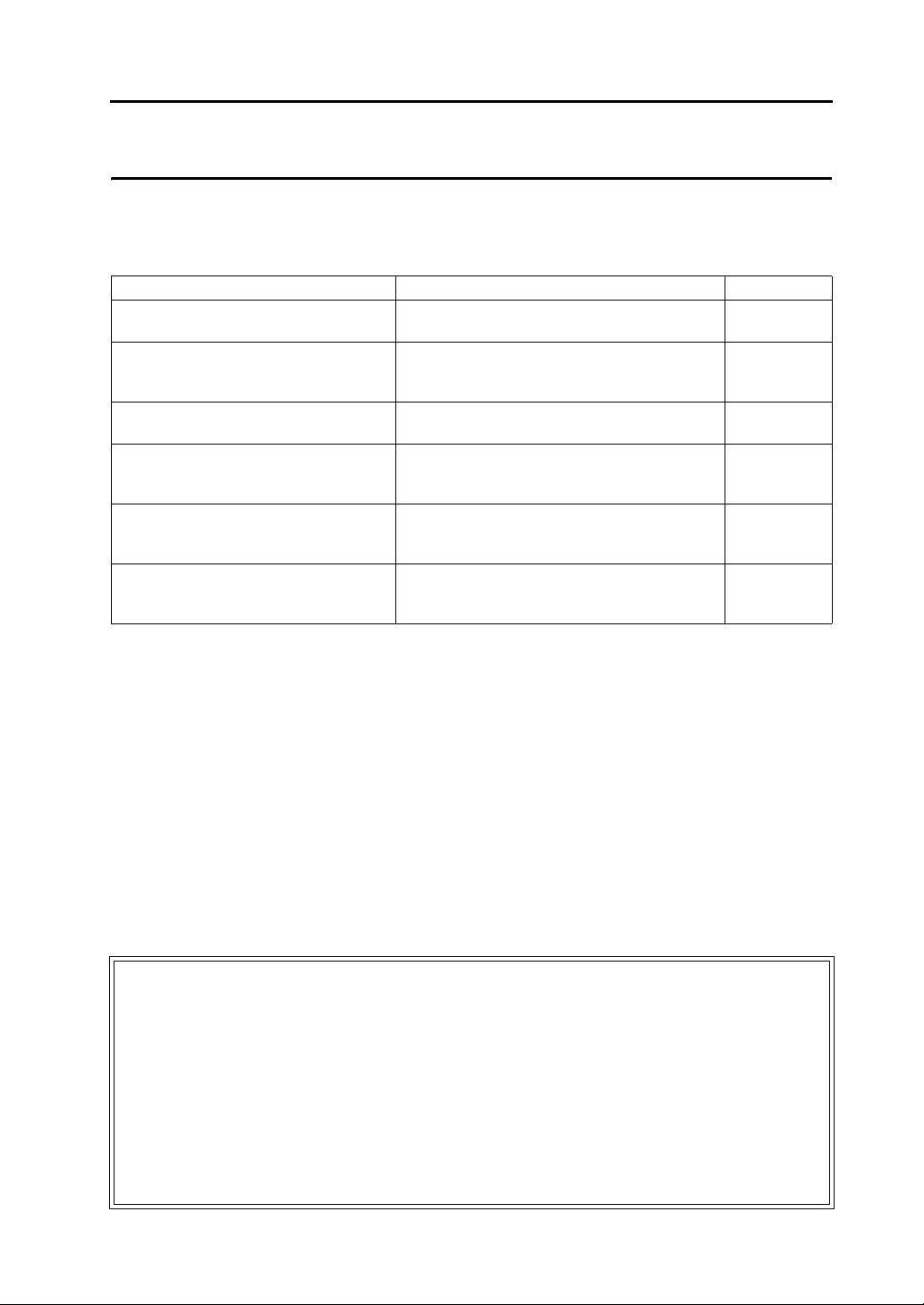
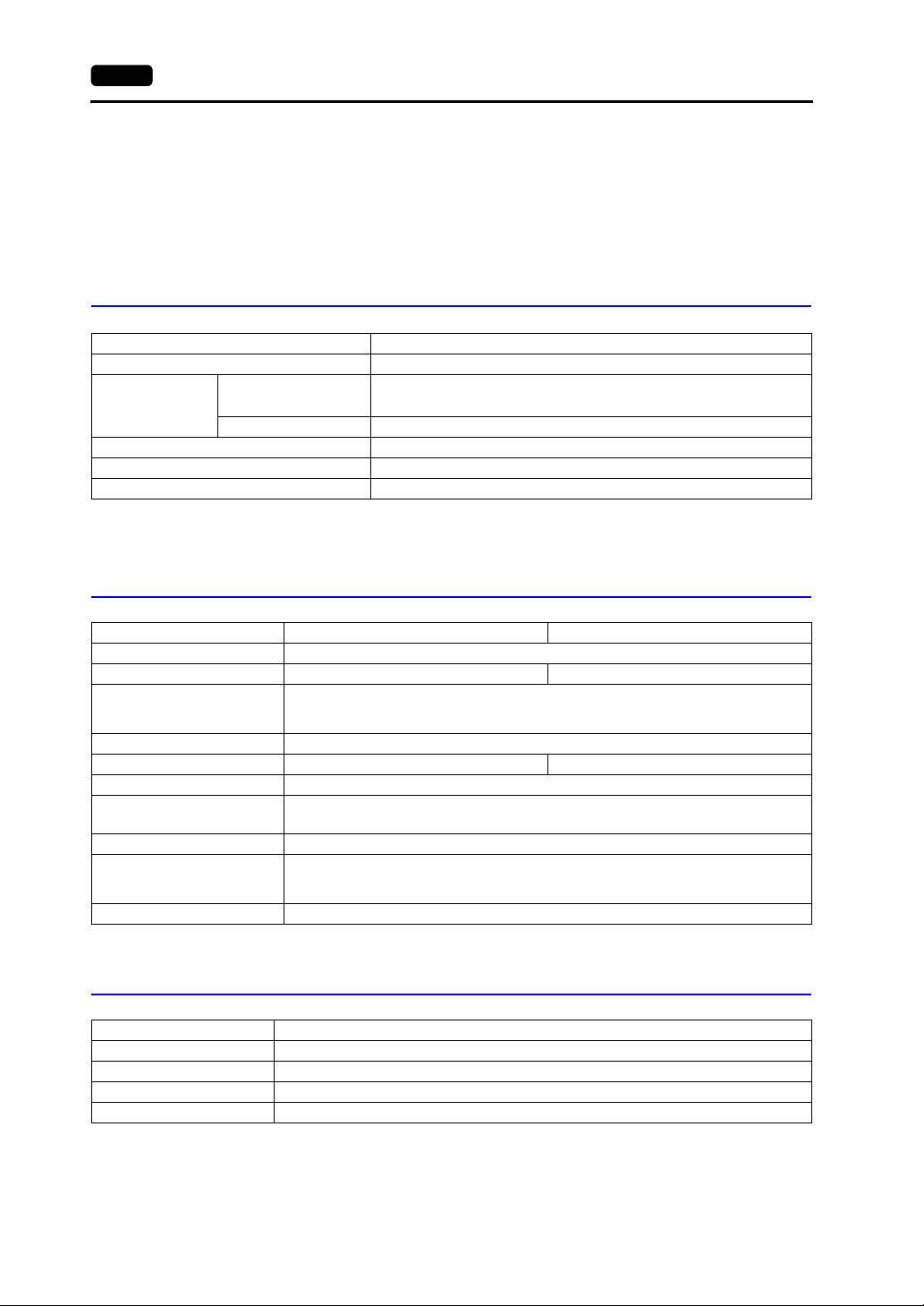
Record of Revisions
Reference numbers are shown at the bottom left corner on the back cover of each manual.
Printing Date Reference No. Revised Contents
April, 2013 2022NE0 First edition
June, 2013 2022NE1 Second edition
Page 3
Preface
Thank you for selecting the Techno Shot series (TS series).
For correct set-up of the TS series, you are requested to read through this manual to understand more about the
product.
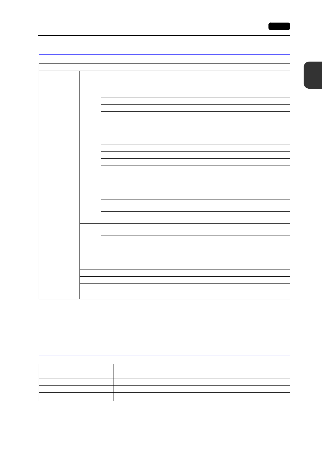
The manuals shown below are related manuals for the TS series. Refer to them as necessary.
Manual Name Contents Reference No.
TS Series Training Manual Screen configuration procedures using V-SFT
version 5 are explained with examples.
TS Series Connection Manual Connecting the TS series with controllers and
setting their communication parameters are
explained.
V8 Series Reference Manual The functions and instructions of the V8 series are
explained.
V8 Series Reference: Additional Functions Additional functions and operations of the V8
series that are available with V-SFT version
5.1.0.0 and later are explained.
V Series Macro Reference An overview of macros as well as macro editor
operations and macro command descriptions are
explained in detail.
V8 Series Operation Manual Information related to the operations of V-SFT
version 5, such as software composition, editing
procedure or limitations, is explained.
For further details about controllers (PLCs, temperature controllers, etc.), refer to the manual issued by each
controller manufacturer.
1203NE
2203NE
1055NE
1060NE
1056NE
1058NE
Notes:
1. This manual may not, in whole or in part, be printed or reproduced without the prior written consent of
Hakko Electronics Co., Ltd.
2. The information in this manual is subject to change without prior notice.
3. Windows and Excel are registered trademarks of Microsoft Corporation in the United States and other
countries.
4. All other company names or product names are trademarks or registered trademarks of their
respective holders.
5. If the specifications of the software do not correspond with the contents of this manual, the software
specifications have priority.
Page 4
Notes on Safe Usage of TS Series
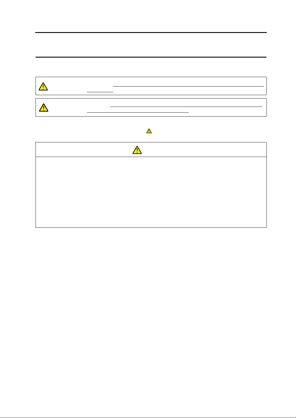
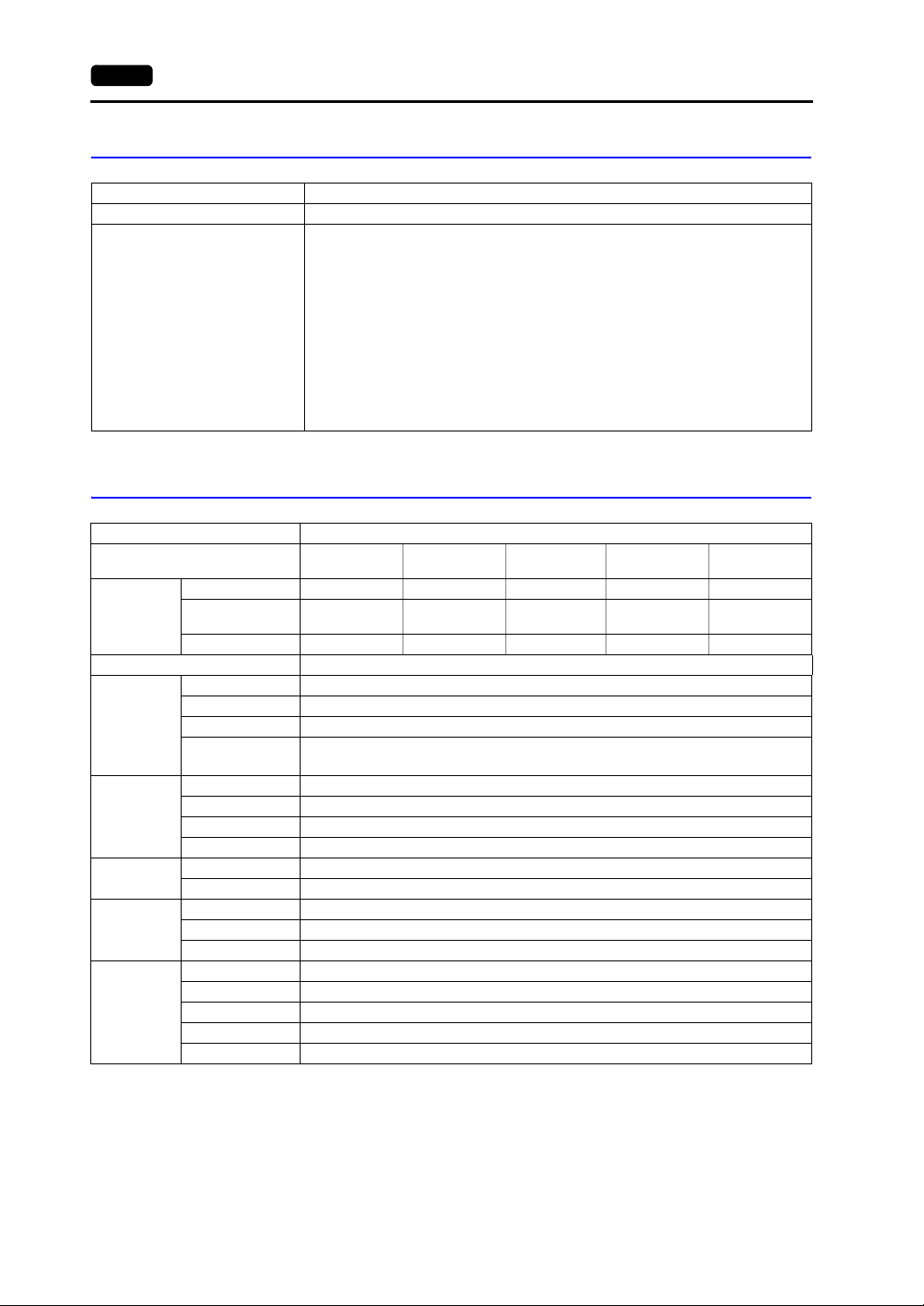
In this manual, you will find various notes categorized under the following levels with the signal words “DANGER”
and “CAUTION”.
DANGER
CAUTION
Note that there is a possibility that the item listed with may have serious ramifications.
Indicates an imminently hazardous situation which, if not avoided, will result in death or
serious injury.
Indicates a potentially hazardous situation which, if not avoided, may result in minor or
moderate injury and could cause property damage.
CAUTION
DANGER
• Never use the output signal of the TS series for operations that may threaten human life or damage the
system, such as signals used in case of emergency. Please design the system so that it can cope with the
malfunctions of a touch switch. A malfunction of a touch switch will result in machine accident or damage.
• Turn off the power supply when you set up the unit, connect new cables or perform maintenance or
inspections. Otherwise, electrical shock or damage may occur.
• Never touch any terminals while the power is on. Otherwise, electric shock may occur.
• The liquid crystal in the LCD panel is a hazardous substance. If the LCD panel is damaged, do not ingest
the leaked liquid crystal. If the liquid crystal spills on skin or clothing, wash off thoroughly with soap.
• Never disassemble, recharge, deform by pressure, short-circuit, reverse the polarity of the lithium battery,
nor dispose of the lithium battery in fire. Failure to follow these conditions will lead to explosion or ignition.
• Never use a lithium battery that is deformed, leaks, or shows any other signs of abnormality. Failure to
follow these conditions will lead to explosion or ignition.
Page 5

CAUTION
• Check the appearance of the unit when it is unpacked. Do not use the unit if any damage or deformation is
found. Failure to do so may lead to fire, damage or malfunction.
• For use in a facility or for a system related to nuclear energy, aerospace, medical, traffic equipment, or
mobile installations, please consult your local distributor.
• Operate (or store) the TS series under the conditions indicated in this manual and related manuals. Failure
to do so could cause fire, malfunction, physical damage or deterioration.
• Understand the following environmental limits for use and storage of MONITOUCH. Otherwise, fire or
damage to the unit may result.
- Avoid locations where there is a possibility that water, corrosive gas, flammable gas, solvents, grinding
fluids or cutting oil can come into contact with the unit.
- Avoid high temperature, high humidity, and outside weather conditions, such as wind, rain or direct
sunlight.
- Avoid locations where excessive dust, salt, and metallic particles are present.
- Avoid installing the unit in a location where vibration or physical shock may be transmitted.
• Equipment must be correctly mounted so that the main terminal of the TS series will not be touched
inadvertently. Otherwise, an accident or electric shock may occur.
• Check periodically that terminal screws on the power supply terminal block and nuts are firmly tightened.
Loosened screws or nuts may result in fire or malfunction.
• Tighten terminal screws on the power supply terminal block equally to a torque of 0.5 to 0.6 N•m (5 to
6 kgf•cm). Improper tightening of screws may result in fire, malfunction, or other serious trouble.
• Tighten the nuts on the TS series equally to the specified torque. Excessive tightening may distort the panel
surface. Loose tightening may cause the unit to come off, malfunction or be short-circuited.
• The TS series has a glass screen. Do not drop or give physical shock to the unit. Otherwise, the screen
may be damaged.
• Connect the cables correctly to the terminals of the TS series in accordance with the specified voltage and
wattage. Over-voltage, over-wattage, or incorrect cable connection could cause fire, malfunction or damage
to the unit.
• Be sure to establish a ground of the TS series. The FG terminal must be used exclusively for the unit with
the level of grounding resistance less than 100 Ω. Otherwise, electric shock or a fire may occur.
• Prevent any conductive particles from entering into the TS series. Failure to do so may lead to fire, damage,
or malfunction.
• Do not attempt to repair the TS series at your site. Ask Hakko Electronics or the designated contractor for
repair.
• Do not repair, disassemble or modify the TS series. Hakko Electronics Co., Ltd. is not responsible for any
damages resulting from repair, disassembly or modification of the unit that was performed by an
unauthorized person.
• Do not use a sharp-pointed tool when pressing a touch switch. Doing so may damage the screen.
• Only experts are authorized to set up the unit, connect the cables or perform maintenance and inspection.
• Lithium batteries contain combustible material such as lithium or organic solvents. Mishandling may cause
heat, explosion or ignition resulting in fire or injury. Read related manuals carefully and handle the lithium
battery correctly as instructed.
• Do not press two or more positions on the screen at the same time. If two or more positions are pressed at
the same time, the switch located between the pressed positions may be activated.
• Take safety precautions during such operations as setting change during running, forced output, start, and
stop. Any misoperation may cause unexpected machine motions, resulting in machine accident or damage.
• In facilities where a failure of the TS series could lead to accident threatening human life or other serious
damage, be sure that the facilities are equipped with adequate safeguards.
• At the time of disposal, the TS series must be treated as industrial waste.
• Before touching the TS series, discharge static electricity from your body by touching grounded metal.
Excessive static electricity may cause malfunction or trouble.
Page 6

[General Notes]
• Never bundle control cables nor input/output cables with high-voltage and large-current carrying cables such
as power supply cables. Keep these cables at least 200 mm away from the high-voltage and large-current
carrying cables. Otherwise, malfunction may occur due to noise.
• When using the TS series in an environment where a source of high-frequency noise is present, it is
recommended that the FG shielded cable (communication cable) be grounded at its ends. However, the cable
may be grounded only at one end if this is necessary due to unstable communication conditions or for any
other reason.
• Plug connectors or sockets of the TS series in the correct orientation. Failure to do so may lead to damage or
malfunction.
• Do not use thinners for cleaning because they may discolor the TS series surface. Use alcohol commercially
available.
• If a data receive error occurs when the TS series and the counterpart (PLC, temperature controller, etc.) are
started at the same time, read the manual for the counterpart unit and remove the error correctly.
• Avoid discharging static electricity on the mounting panel of the TS series. Static charges can damage the unit
and cause malfunctions. Otherwise, malfunction may occur due to noise.
• Avoid prolonged display of any fixed pattern. Due to the characteristic of liquid crystal displays, an afterimage
may occur. If prolonged display of a fixed pattern is expected, use the auto OFF function of the backlight.
[Notes on LCD]
Note that the following conditions may occur under normal circumstances.
• The response time, brightness and colors of the TS series may be affected by the ambient temperature.
• Tiny spots (dark or luminescent) may appear on the display due to the liquid crystal characteristics.
• Each unit varies slightly with respect to brightness and colors.
Page 7

Preface
Notes on Safe Usage of TS Series
Chapter 1 Product Outline
1. Features.............................................................................................................. 1-1
2. Models and Peripheral Equipment...................................................................... 1-3
Models............................................................................................................................. 1-3
Peripheral Equipment...................................................................................................... 1-4
3. System Composition........................................................................................... 1-5
TSi Series System Composition...................................................................................... 1-5
TS Series System Composition ...................................................................................... 1-6
Chapter 2 Specifications
1. Specifications...................................................................................................... 2-1
General Specifications .................................................................................................... 2-1
Installation Specifications................................................................................................ 2-2
Display Specifications ..................................................................................................... 2-2
Touch Switch Specifications ........................................................................................... 2-2
Interface Specifications ................................................................................................... 2-3
Clock and Backup Memory Specifications ...................................................................... 2-3
Drawing Environment...................................................................................................... 2-4
Display Function Specifications ...................................................................................... 2-4
Function Performance Specifications.............................................................................. 2-5
2. Dimensions and Panel Cut-out........................................................................... 2-6
External Dimensions and Panel Cut-out Dimensions for TS1100................................... 2-6
External Dimensions and Panel Cut-out Dimensions for TS1070................................... 2-7
3. Names and Functions of Components................................................................ 2-8
4. Serial Connector ............................................................................................... 2-10
COM1: RS-422/485 Communication Connector ........................................................... 2-10
COM2: RS-232C/COM3:RS-485 Communication Connector ....................................... 2-11
5. USB Connector................................................................................................. 2-12
USB-A (Master Port) ..................................................................................................... 2-12
USB-miniB (Slave Port)................................................................................................. 2-18
Securing USB Cables ................................................................................................... 2-23
Space for USB Connectors Behind the Unit ................................................................. 2-24
6. LAN Connector (TS1100i/TS1070i Only)......................................................... 2-25
LAN Connector.............................................................................................................. 2-25
Wiring ............................................................................................................................ 2-25
Contents
Page 8

Chapter 3 Installation
1. Mounting Procedure ............................................................................................3-1
Mounting Procedure ........................................................................................................ 3-1
Mounting Angle ............................................................................................................... 3-2
2. Power Supply Cable Connection.........................................................................3-3
Power Supply Cable Connection..................................................................................... 3-3
Chapter 4 Handling of TS Series Components
1. Coin-type Lithium Battery....................................................................................4-1
Battery Usage ................................................................................................................. 4-1
Time for Battery Replacement......................................................................................... 4-1
Battery Replacement....................................................................................................... 4-1
Notes on Battery: EU Directive 2006/66/EC.................................................................... 4-5
2. DIP Switches.......................................................................................................4-6
DIP Switch (DIPSW) Setting ........................................................................................... 4-6
Chapter 5 TS Series Operations
1. Before Operation.................................................................................................5-1
Procedure before Operation............................................................................................ 5-1
Transferring Screen Data to TS Series for the First Time ............................................... 5-2
2. Main Menu Screen ..............................................................................................5-3
Displaying the Main Menu Screen................................................................................... 5-3
Main Menu Screen .......................................................................................................... 5-4
[Main Menu] Switch ......................................................................................................... 5-5
Main Menu Screen Composition ..................................................................................... 5-5
1. RUN ..................................................................................................................... 5-6
2. Language Selection ............................................................................................. 5-6
3. Communication Parameter .................................................................................. 5-7
4. Ethernet (TS1100i/TS1070i Only)........................................................................ 5-8
4-1. IP Address Setting for the TS Series .......................................................... 5-9
5. SRAM/Clock ...................................................................................................... 5-12
5-1. Date and Time Adjustment ....................................................................... 5-13
5-2. Formatting SRAM ..................................................................................... 5-13
6. Extension Program Information ......................................................................... 5-14
7. Storage Transfer ................................................................................................ 5-15
7-1. Storage Folder Configuration.................................................................... 5-17
7-2. Transferring Screen Data.......................................................................... 5-18
7-3. Saving Backup Copies of SRAM .............................................................. 5-24
7-4. Storage Data Deletion .............................................................................. 5-26
7-5. Message Dialog Displayed during Data Transfer
(between TS and Storage)........................................................................ 5-27
8. Brightness Adjustment ....................................................................................... 5-28
Page 9

9. I/O Test .............................................................................................................. 5-29
9-1. Self-loop Test............................................................................................ 5-30
9-2. USB Test .................................................................................................. 5-34
9-3. Print Test .................................................................................................. 5-34
9-4. Touch Switch Test .................................................................................... 5-35
9-5. Keyboard Selection................................................................................... 5-37
10. Extended Setting (TS1100i/TS1070i Only)........................................................ 5-38
10-1. Registering/Unregistering the License
11. Extended Function Setting................................................................................. 5-41
11-1. Setting Local Port Number........................................................................ 5-42
3. System Menu.................................................................................................... 5-43
Types of the System Menu Switches ............................................................................ 5-43
Functions of the System Menu Switches ...................................................................... 5-43
Chapter 6 Error Handling
1. Error Messages................................................................................................... 6-1
1. Communication Error ........................................................................................... 6-1
2. Data Loading ....................................................................................................... 6-2
3. Warning ............................................................................................................... 6-3
4. Touch Switch Is Active......................................................................................... 6-3
2. Troubleshooting .................................................................................................. 6-4
In the Event of an Error ................................................................................................... 6-4
Probable Symptoms........................................................................................................ 6-4
for the Remote Desktop Function ............................................................. 5-39
Chapter 7 Inspection and Maintenance
1. Inspection and Maintenance............................................................................... 7-1
Daily Inspection............................................................................................................... 7-1
Periodical Inspection ....................................................................................................... 7-1
2. Warranty Policy................................................................................................... 7-2
Inquiries about Failure..................................................................................................... 7-2
Warranty Period .............................................................................................................. 7-2
Free-of-charge Repair..................................................................................................... 7-2
Chargeable Repair .......................................................................................................... 7-2
Inquiry Form ....................................................................................................................7-3
Page 10

1
1. Features
2. Models and Peripheral Equipment
3. System Composition
Product Outline
Page 11
1. Features 1-1
1. Features
The Techno Shot series (the TS series) features:
1. Low-cost standard model
The TS series is a high-performance low-cost model with a high degree of usability.
This is a high-resolution, high-definition programmable display unit that offers 65,536 maximum
displayable colors and WVGA (800 × 480 dots) resolution, incorporating a LCD with an LED
backlight.
2. Ethernet-enabled (TS1100i and TS1070i only)
The TS series, while it is a low-cost model, supports Ethernet connection.
The following network systems via Ethernet can be achieved with the TS series.
• Remote desktop
Screens on a server computer can be displayed on the TS series.
Computer functions become available even at worksites where computers cannot be brought
in.
* Using the remote desktop function requires licensing.
• Network camera
Images taken by network cameras can be viewed on the TS series.
Angles of network cameras at remote locations can be changed by operation from the TS
series.
• FTP server
The TS series can serve as the FTP server.
Via the FTP client tool in the computer, storage (e.g. USB memory) connected to the TS series
can be accessed.
• MES interface
From the TS series via the remote monitoring software “V-Server”, insertion, retrieval, deletion,
and update can be executed on databases.
• TELLUS and V-Server Lite (remote maintenance software)*
TELLUS and V-Server Lite enable monitoring, operating, and gathering information from the
TS series at remote locations.
* This software has minimum required functions, and is supplied with the V-SFT-5 (version 5.4.28.0 or
later).
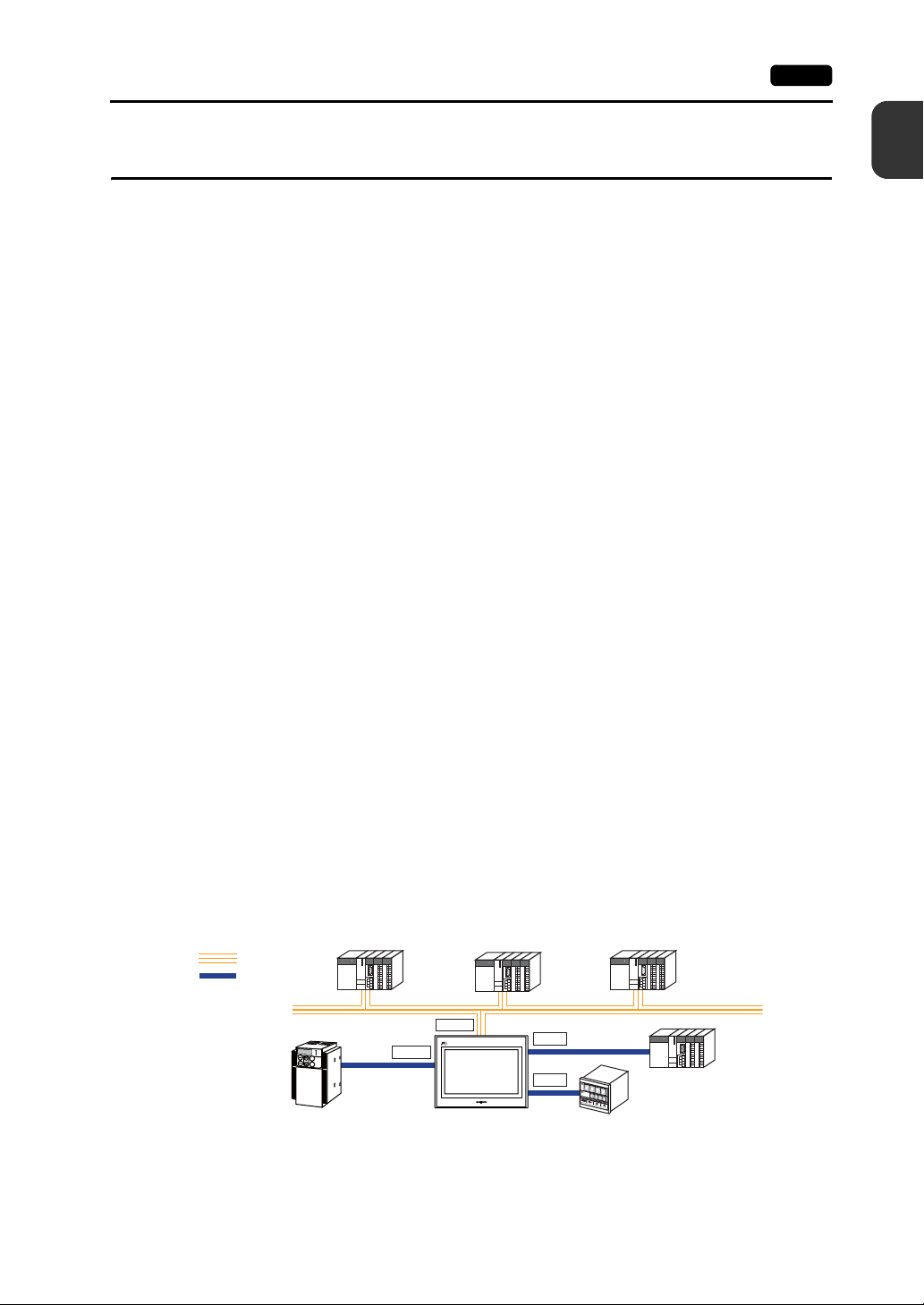
3. 8-way communication
A maximum of eight devices, such as PLCs or peripheral equipment, of different models or
manufacturers can be connected to one unit of the TS series over a network in combination with
Ethernet (max. 8 protocols) and serial communications (max. 3 protocols). A unit can
communicate with eight types of devices at one time and exchange data among the connected
devices.
1
Product Outline
Connection example: serial 3 ports + Ethernet
Ethernet
Serial
K
E
Y
P
A
D
Hz
C
O
N
T
R
O
L
A
P
R
O
M
O
D
E
KW
PRG
R
E
S
E
T
R
U
N
FUNC
D
A
T
A
S
T
O
P
Inve
r
ter
Manufacturer
A
COM1
LAN
TS
Manufacturer
B
COM2
COM3
A maximum of
Manufacturer
C
5 types of
devices can be
connected.
Ethernet
* The same connector is used for
COM2 and COM3.
Communicating via RS-232C
(COM2) and via RS-485 (COM3)
can take place at the same time.
Page 12

1-2 1. Features
4. Handling operation logs
Logs of screen operations (operation logs) can be output to storage (e.g. USB memory).
If errors occur, such logs should be helpful for cause analysis.
Operation logs can be browsed on the TS series.
5. Security function
Screen display or operation can be controlled according to security levels set for screens or items.
Security levels can be changed at the time of user login.
Page 13
2. Models and Peripheral Equipment 1-3
2. Models and Peripheral Equipment
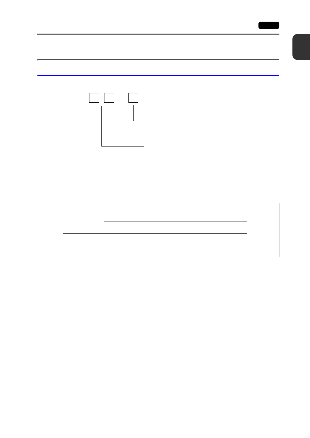
Models
The model name consists of the following information.
TS1
The series consists of the following models:
Analog resistance film type
Series Model Specifications Remarks
TS1100 series
10.2-inch wide
TS1070 series
7.0-inch wide
TS1100
TS1100i
TS1070
TS1070i
0
Functional specification
i: With built-in LAN port
None: Without built-in LAN port
Screen size
TFT color, 800 × 480 dots, without built-in LAN port, DC
power supply
TFT color, 800 × 480 dots, with built-in LAN port, DC power
supply
TFT color, 800 × 480 dots, without built-in LAN port, DC
power supply
TFT color, 800 × 480 dots, with built-in LAN port, DC power
supply
10: 10.2-inch wide
07: 7.0-inch wide
1
Product Outline
CE/KC
approved
Page 14
1-4 2. Models and Peripheral Equipment
Peripheral Equipment
The following are the options for the TS series:
Drawing Tool
V-SFT-5 (configuration software)
Application software for editing screen data for MONITOUCH.
Use version 5.4.28.0 or later with the TS series.
Applicable OS:
Windows 98SE/NT4.0/Me/2000/XP/XP 64 Edition/Vista (32-bit, 64-bit)/7 (32-bit, 64-bit)/
8 (32-bit, 64-bit)
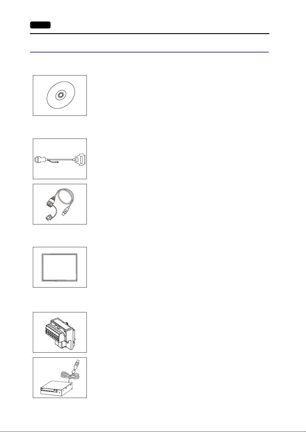
Cables
D9-D25 (D-sub 9-pin-to-25-pin conversion cable) 0.3 m
Conversion cable used for connecting the communication cable for the CN1 (D-sub 25-pin)
in the V6/V7 series to the COM1 (D-sub 9-pin) in the TS series.
UA-FR (for USB-A port) 1 m
Cable for USB-A (master), with which connection from the front of the control cabinet is
allowed.
Waterproof gasket
Other Options
+5V
SG
+SD
-SD
+RD
-RD
FG
TS1xx0-WP
Waterproof gasket to make the front panel protection compliant with IP65.
TS1100-WP → TS1100 series
TS1070-WP → TS1070 series
TC-D9 (terminal converter)
Used for connection between COM1 (D-sub 9-pin) of the TS series and a controller at the
RS-422/485 terminal block.
USB-CFREC (USB CF card recorder)
Unit that connects to the USB-A port and makes a CF card available.
Page 15
3. System Composition 1-5
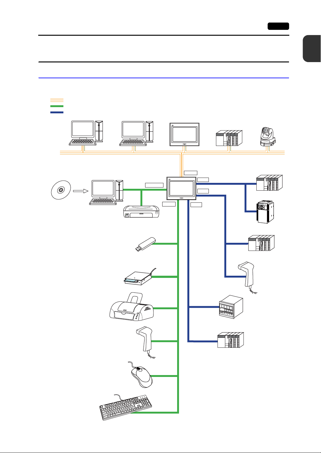
3. System Composition
TSi Series System Composition
System configurations available with the TSi series:
Ethernet
USB
Serial
Computer (PC) Computer (PC)
The V/TS series
configuration software
ޟV-SFT-5ޠ
Creating
screens
Computer (PC)
Transferring
screen data
PictBridge
USB-miniB
Printer (PictBridge)
USB-A
TSi
TSi
LAN
COM3
COM1
COM2
(RS-485)
PLC
(RS-422/485)
(RS-232C)
Network camera
Ethernet
PLC
Temperature
controller, inverter
K
E
Y
P
A
D
Hz
C
O
N
T
R
O
L
A
PR
O
M
O
D
E
KW
PRG
R
E
S
E
T
R
U
N
FUNC
D
A
T
A
S
T
O
P
In
ve
r
te
r
1
Product Outline
USB memory
USB CF card recorder
ޟUSB-CFRECޠ
Printer
Barcode reader
Keyboard
Mouse
Barcode reader
Temperature
controller, inverter
PLC
* The same connector is used for COM2 and
COM3. Communicating via RS-232C
(COM2) and via RS-485 (COM3) can take
place at the same time.
PLC
Page 16
1-6 3. System Composition
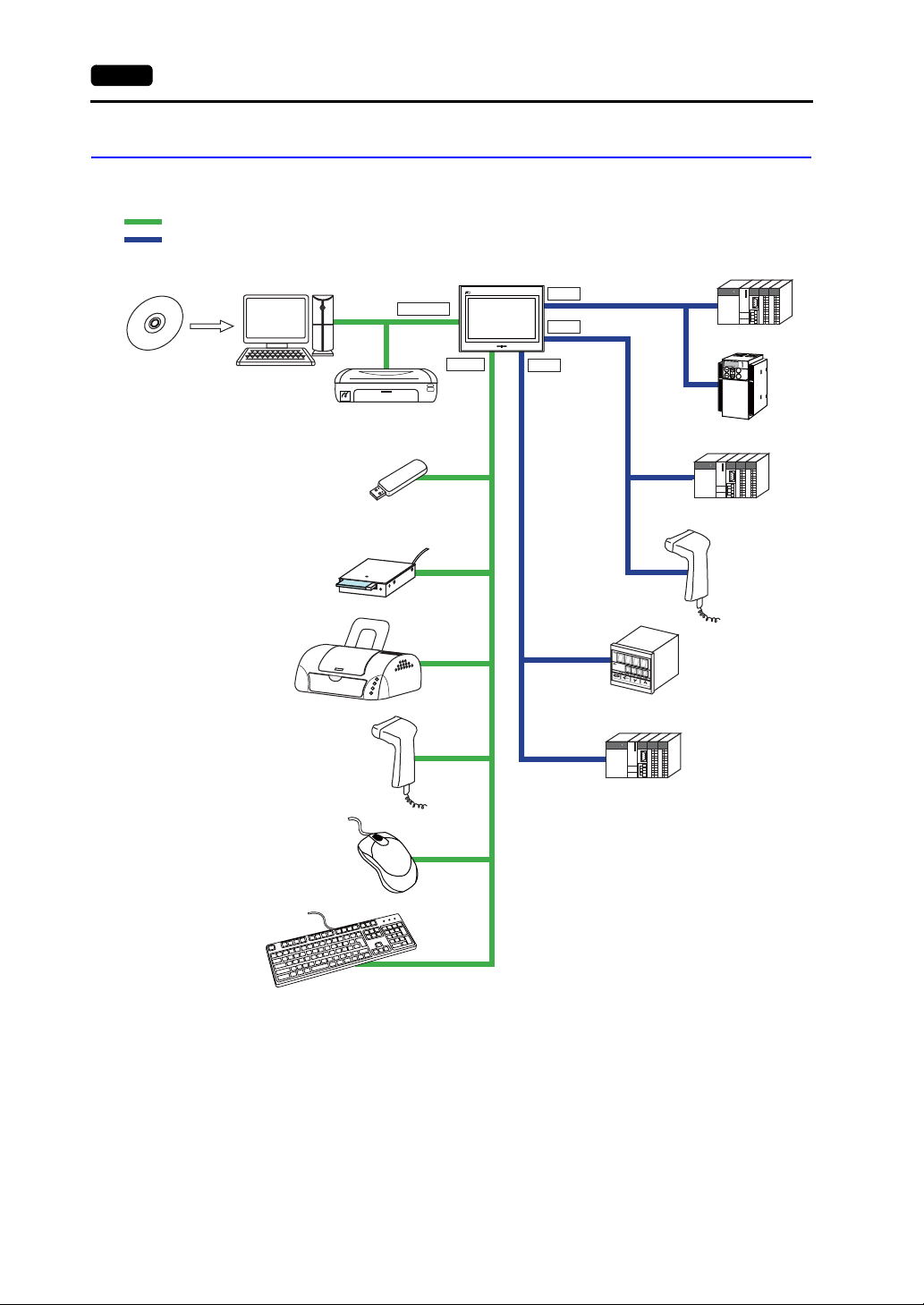
TS Series System Composition
System configurations available with the TS series:
USB
Serial
The V/TS series
configuration software
ޟV-SFT-5ޠ
Creating
screens
Computer (PC)
Transferring
screen data
PictBridge
Printer (PictBridge)
USB-miniB
USB-A
TS
COM3
COM1
COM2
(RS-485)
(RS-422/485)
(RS-232C)
PLC
Temperature
controller, inverter
K
E
Y
P
A
D
Hz
C
O
N
T
R
O
L
A
PR
O
M
O
D
E
KW
PRG
R
E
S
E
T
R
U
N
FUNC
D
A
T
A
S
T
O
P
In
ve
r
te
r
USB memory
USB CF card recorder
ޟUSB-CFRECޠ
Printer
Barcode reader
Mouse
Keyboard
Barcode reader
Temperature
controller, inverter
PLC
* The same connector is used for COM2 and
COM3. Communicating via RS-232C
(COM2) and via RS-485 (COM3) can take
place at the same time.
PLC
Page 17

2
1. Specifications
2. Dimensions and Panel Cut-out
3. Names and Functions of Components
4. Serial Connector
5. USB Connector
6. LAN Connector (TS1100i/TS1070i Only)
Specifications
Page 18
1. Specifications
1. Specifications 2-1
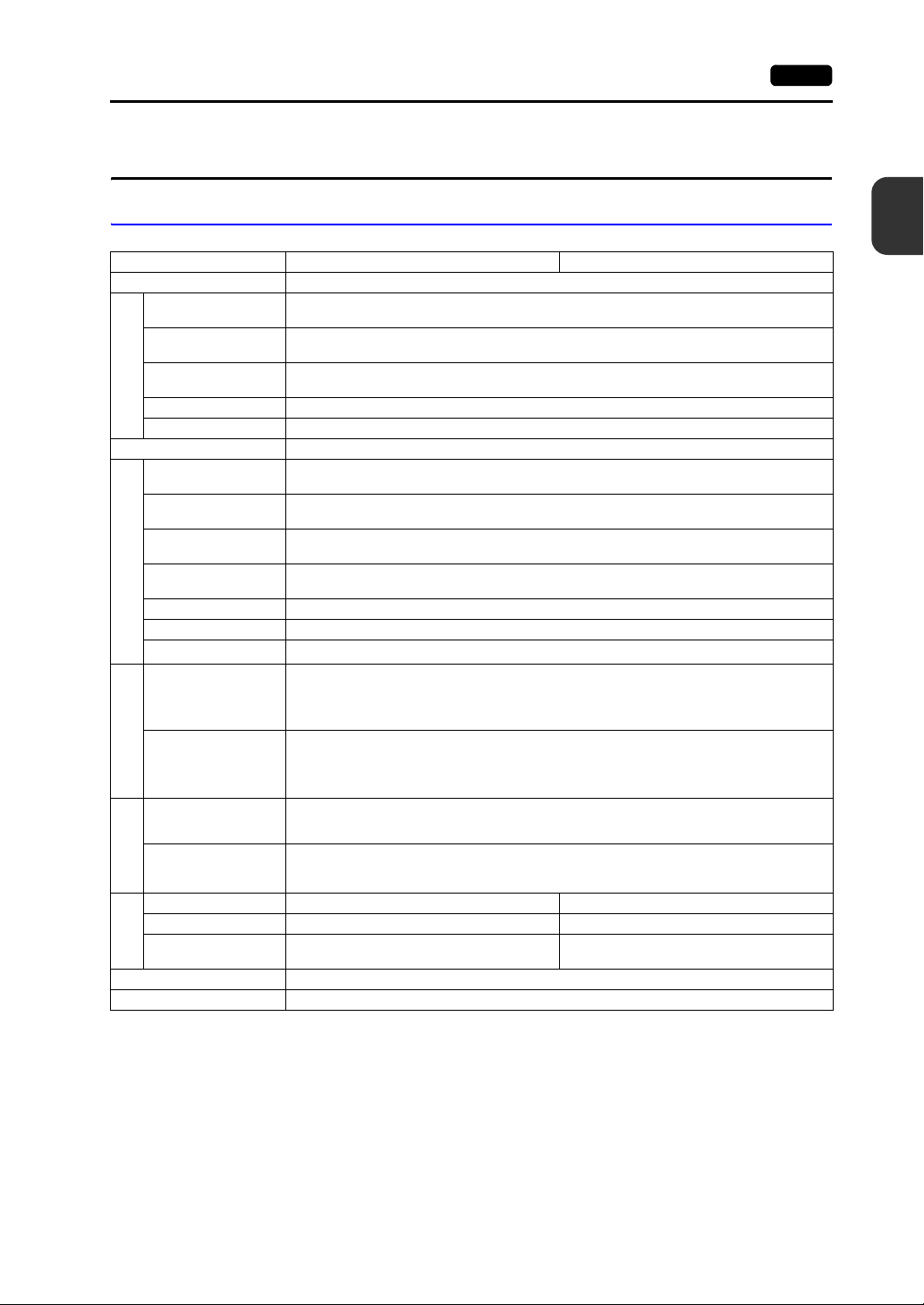
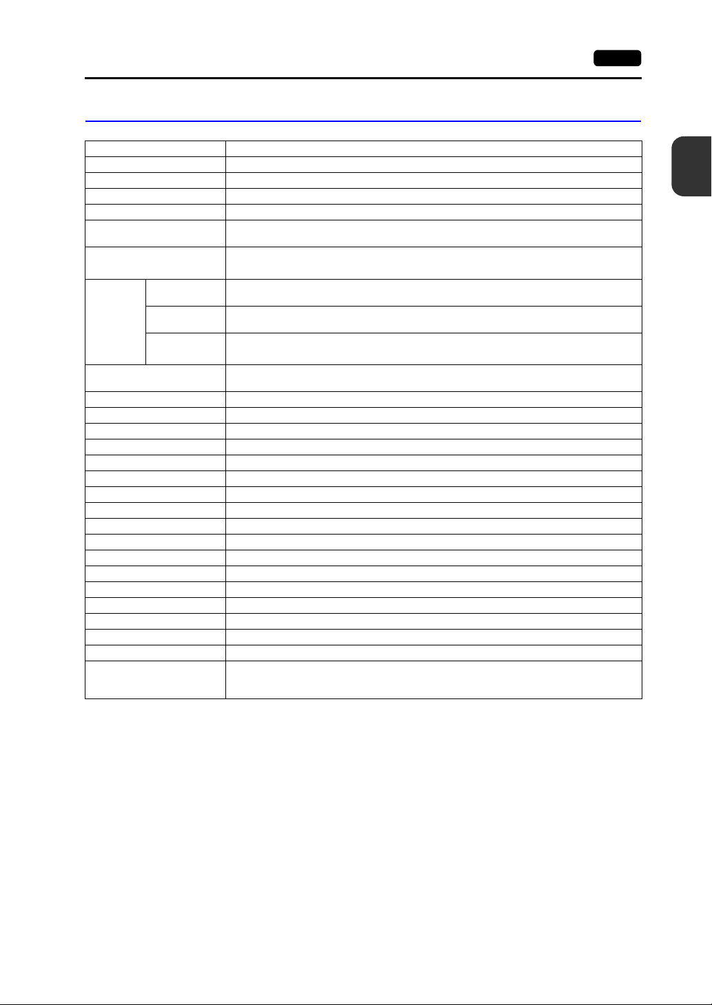
General Specifications
Item TS1100 TS1070
Standards CE (EN61000-6-2, EN61000-6-4), KC
Permissible Range of
Voltage
Permissible Momentary
Power Failure
Power Consumption
(Maximum Rating)
Power Supply
Rush Current 22 A or less (within 2 ms)
Withstand Voltage DC external terminals to FG: 500 VAC, 1 minute
Insulation Resistance DC external terminals to FG: 500 VDC, 10 MΩ or above
Operational Ambient
Temperature
Storage Ambient
Temperature
Operational Ambient
Humidity
Storage Ambient
Temperature
Altitude 2000 m or less
Physical Environment
Atmosphere No corrosive gas, no excessive dust, and no conductive dust
Contamination Level
Vibration Resistance
*2
Vibration frequency: 9 to 150 Hz Constant acceleration: 9.8 m/s
85 %RH or less (without dew condensation)
85 %RH or less (without dew condensation)
Vibration frequency: 5 to 9 Hz Half-amplitude: 3.5 mm,
JIS B 3502 (IEC61131-2) compliant
3 directions of X, Y, and Z: 10 times
JIS B 3502 (IEC61131-2) compliant
Shock Resistance
Mechanical Working Conditions
Noise Resistance
Noise voltage: 1000 Vp-p, pulse width: 1 µs, rising time: 1 ns
Peak acceleration: 147 m/s
3 directions of X, Y, and Z: 3 times each
(Measured by using a noise simulator)
24 VDC ± 10 %
Within 1 ms
16.0 W or less
0 °C to +50 °C
−10 °C to +60 °C
*1
*1
Contamination level: 2
2
(15 G),
*1
*1
2
(1 G),
2
Specifications
Electrical
Static Electricity
Discharge Resistance
Working Conditions
Compliant with IEC61000-4-2, contact: 6 kV, air: 8 kV
Weight Approx. 1.5 kg Approx. 0.9 kg
Dimensions W × H × D 283.0 × 220.0 × 42.0 mm 215.0 × 155.0 × 42.0 mm
Panel Cut-out
Mounting
Conditions
Dimensions
+0.5
257.0 × 199.0 mm 189.0 × 134.0 mm
−0
+0.5
−0
+0.5
−0
Case Color Black
Material PC / PS
*1 Use MONITOUCH in the environment whose wet-bulb temperature is 39 °C or less. Otherwise, MONITOUCH
may be damaged.
*2 This is an index that expresses the degree of conductive contamination in the environment where
MONITOUCH is used.
“Contamination level 2” indicates the condition where only non-conductive contamination occurs. However,
due to condensation, temporary conductive contamination may occur.
+0.5
−0
Page 19
2-2 1. Specifications
CE Marking
• The TS series complies with following EMC Directives:
EN61000-6-2, EN61000-6-4
• The TS series is identified as a class-A product in industrial environments. In the case of use in a
domestic environment, the TS series is likely to cause electromagnetic interference. Preventive
measures should thereby be taken as appropriate.
Installation Specifications
Item Specifications
Grounding Less than 100 Ω, FG/SG separated
Protection Structure
Cooling System Cooling naturally
Structure Inserted in a mounting panel
Appropriate Mounting Panel Thickness 1.5 to 5 mm
Front Panel
Rear Case Compliant with IP20
*1 Protection structure for the front when the TS series is mounted on the mounting panel
*2 The strength differs depending on the material of the mounting panel. Check the environment where the TS
series is used.
*1
With waterproof gasket “TS1xx0-WP” (optional): IP65-compliant
Without waterproof gasket “TS1xx0-WP” (optional): IP40-compliant
Display Specifications
*2
Item TS1100 TS1070
Display Device TFT color
Display Size 10.2-inch wide 7.0-inch wide
Colors
Display Resolution (W × H) 800 × 480 dots
Dot Pitch (W × H) 0.2775 × 0.276 mm 0.192 × 0.1805 mm
Backlight LED
Backlight Life
(average life of backlight only)
Backlight Auto OFF Function Always ON, random setting
Brightness Adjustment
Surface Sheet Material PET, 188 µm
*1 Time until the surface brightness becomes 50 % of the initial value at an ambient temperature of 25 °C.
65,536 colors (without blinks)
32,768 colors (with blinks)
128 colors (with 16-color blinks)
Approx. 40,000 hours
*1
System menu: 3 levels
Main Menu screen (Bright Adjustment screen): 128 levels
Macro: 128 levels
Touch Switch Specifications
Item Specifications
Method Analog resistance film type
Switch Resolution 1024 × 1024
Mechanical Life One million activations or more
Surface Treatment Anti-glare coating
Page 20
Interface Specifications
Item Specifications
Applicable
Standards
Synchronization Asynchronous type
Data Length 7- or 8-bit
Parity None, odd, even
Stop Bit 1- or 2-bit
Baud Rate
Applications PLC, temperature controller, etc.
Applicable
Standards
Synchronization Asynchronous type
Data Length 7- or 8-bit
Parity None, odd, even
Stop Bit 1- or 2-bit
Baud Rate 4800, 9600, 19200, 38400, 57600, 76800, 115 Kbps
Applications PLC, temperature controller, barcode reader, etc.
Applicable
Standards
Baud Rate
Applications
Applicable
Standards
USBminiB
Baud Rate
Applications Screen data transfer, PictBridge-compatible printer
D-sub 9-pin
(COM1/2/3)
USB Connector
(USB-A / B)
Ethernet Port
100BASE-TX /
10BASE-T
*4
(LAN)
COM1
COM2
COM3
USB-A
Applicable Standards IEEE802.3u (100BASE-TX), IEEE802.3 (10BASE-T)
Baud Rate 10 Mbps, 100 Mbps
Protocol TCP/IP, UDP/IP
Functions Auto-MDIX
Recommended cable
Applications Screen data transfer, PLC, etc.
*1 Use DIP switches to switch between RS-422 (4-wire connection) and RS-485 (2-wire connection). For more
information, refer to page 4-6.
*2 For more information, refer to the TS Series Connection Manual.
*3 The same connector is used for RS-232C and RS-485 (2-wire connection) ports. Communicating via RS-232C
(COM2) and RS-485 (COM3) can take place at the same time.
*4 Provided as standard for TS1100i and TS1070i only
*5 Both straight and cross cables are usable, irrespective of the presence or absence of a hub.
1. Specifications 2-3
RS-422 (4-wire connection) / RS-485 (2-wire connection)
4800, 9600, 19200, 38400, 57600, 76800, 115 Kbps
(For PPI/MPI connection with a Siemens PLC: 187.5 Kbps
COM2: RS-232C / COM3: RS-485 (2-wire connection)
USB versions 2.0 and 1.1
Version 2.0: High-speed 480 Mbps
Version 1.1: Low-speed 1.5 Mbps, full-speed 12 Mbps
Printer (EPSON STYLUS PHOTO series), USB memory, USB-CFREC,
keyboard, mouse, etc.
USB versions 2.0 and 1.1
Version 2.0: High-speed 480 Mbps
Version 1.1: Low-speed 1.5 Mbps, full-speed 12 Mbps
*5
100 Ω UTP (unshielded twist-pair cable), category 5, max. 100 m long
*1
2
Specifications
*2
)
*3
Clock and Backup Memory Specifications
Item Specifications
Battery Specification Coin-type lithium primary cell (CR2032)
Backup Memory SRAM 128 kbytes
Backup Period 3 years from the date of manufacturing (ambient temperature at 25 °C)
Calendar Accuracy
* The range of deviation may increase, depending on the ambient temperature. Check and correct the clock
Monthly deviation ±5 sec (ambient temperature at 25 °C)
periodically.
*
Page 21
2-4 1. Specifications
Drawing Environment
Item Specifications
Drawing Method Exclusive configuration software
Name of exclusive configuration software: V-SFT-5 (version 5.4.28.0 or later)
Drawing Tool
Personal computer: Pentium III 800 MHz or above (Pentium IV 2.0 GHz or above
OS: Windows 98SE/NT4.0/Me/2000/XP/XP 64 Edition/Vista (32-bit,
Memory: 512 MB or more
Hard disk capacity: Free space of approx. 1.5 GB or more
CD-ROM disk drive: 24X or above recommended
Display: Resolution 1024 × 768 or above
Others: Microsoft .NET Framework 4.0 or 4.5
recommended)
64-bit)/ 7 (32-bit, 64-bit)/ 8 (32-bit, 64-bit)
Screen color: 16 bits or more
(If a PC running on Windows XP/Vista/7/8 does not have .NET
Framework 4.0 or 4.5, Framework 4.0 will automatically be installed
on the PC.)
Display Function Specifications
Item Specifications
Interface Language
Characters
Font Bitmap font, Gothic font, Windows font
Character
Size
Number of
Displayable
Characters
Character
Properties
Graphics
Graphic
Properties
*1
1/4-size, 1-byte ANK code Latin 1 ASCII code ASCII code ASCII code
2-byte 16-dot JIS #1, 2 levels −
2-byte 32-dot JIS #1 level −−−−
1/4-size 8 × 8 dots
1-byte 8 × 16 dots
2-byte 16 × 16 dots or 32 × 32 dots
Enlargement
Factor
Display Resolution 800 × 480 dots
1/4-size 100 characters × 60 lines
1-byte 100 characters × 30 lines
2-byte 50 characters × 30 lines
Display Properties Normal, reverse, blink, bold, shadow, transparent
Colors 65,536 colors (without blinks), 32,768 colors (with blinks), 128 colors (with 16-color blinks)
Lines Line, continuous line, box, parallelogram, polygon
Circles Circle, arc, sector, ellipse, elliptical arc
Others Tile patters
Line Types 6 types (thin, thick, dot, chain, broken, two-dot chain)
Tile Patterns 16 types (including user-definable 8 patterns)
Display Properties Normal, reverse, blink
Colors 65,536 colors (without blinks), 32,768 colors (with blinks), 128 colors (with 16-color blinks)
Color Selection Foreground, background, boundary (line)
*1 In addition, the following fonts are available.
Gothic, English/Western Europe HK Gothic, English/Western Europe HK Times, Central Europe, Cyrillic,
Greek, Turkish, Baltic
For more information, refer to the V8 Series Reference Manual.
*2 Applicable when Gothic font is used.
With Windows fonts, the allowable number of points ranges from 6 to 999.
For more information on the number of points for Windows fonts, refer to the V8 Series Reference: Additional
Functions.
Japanese
English/Western
Europe
*2
: 8, 9, 10, 11, 12, 14, 16, 18, 20, 22, 24, 26, 28, 36, 48, 72
Point
X: 1 to 8 times, Y: 1 to 8 times
Chinese
(Traditional)
Chinese
(traditional)
(Simplified)
(simplified)
Chinese
Chinese
Korean
Hangul
(without Kanji)
Page 22
Function Performance Specifications
Item Specifications
Screens Max. 4000
Screen Memory Flash memory: Approx. 10.5 MB (variable depending on the font)
Switch 1024 per screen
Switch Actions Set, reset, momentary, alternate, to light
Lamp
Graph
Numerical Data
Display
Data
Setting
Sampling
Graphic Library Max. 2560
Overlap Library Max. 4000
Data Blocks Max. 1024
Messages Max. 32768 lines
Patterns Max. 1024
Macro Blocks Max. 1024
Page Blocks Max. 2048
Direct Blocks Max. 1024
Screen Blocks Max. 1024
Data Sheets Max. 1024
Screen Library Max. 4000
Comments Max. 32767
Device Memory Map Max. 32 × 8 (PLC1 to 8)
Time Display Provided
Hard Copy Provided
Buzzer Provided, 3 sounds (short beep, long beep, continuous beep)
Auto OFF Function Always ON, random setting
Self-diagnostic Function
Character
Display
Message
Display
*1 The number of setting memory locations is limited to 1024 per screen.
*2 Layer: 5 layers per screen (base + 4 overlap displays including global overlap)
Reverse, blink, exchange of graphics
1024 per screen
Pie, bar, panel meter and closed area graph: No limitation
Statistics and trend graphs: Max. 256 per layer
No limitation
No limitation
No limitation
Maximum number of characters per line: 100 one-byte characters
Sampling display of buffer data
(Constant sampling, bit synchronization, alarm logging, time order alarming, alarm function)
Switch self-test function
Communication parameter setting check function
Communication check function
*1
*1
*1
*1
1. Specifications 2-5
2
Specifications
*2
Page 23
2-6 2. Dimensions and Panel Cut-out
2. Dimensions and Panel Cut-out
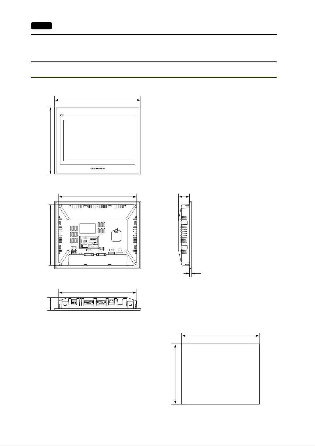
External Dimensions and Panel Cut-out Dimensions for TS1100
• Front View
220.0
• Rear View
198.0
283.0
256.0
(Unit: mm)
• Side View
36.0
• Bottom View
42.0
256.0
6.0
• Panel Cut-out Dimensions
257.0
-0
+0.5
199.0
+0.5
-0
Page 24
2. Dimensions and Panel Cut-out 2-7
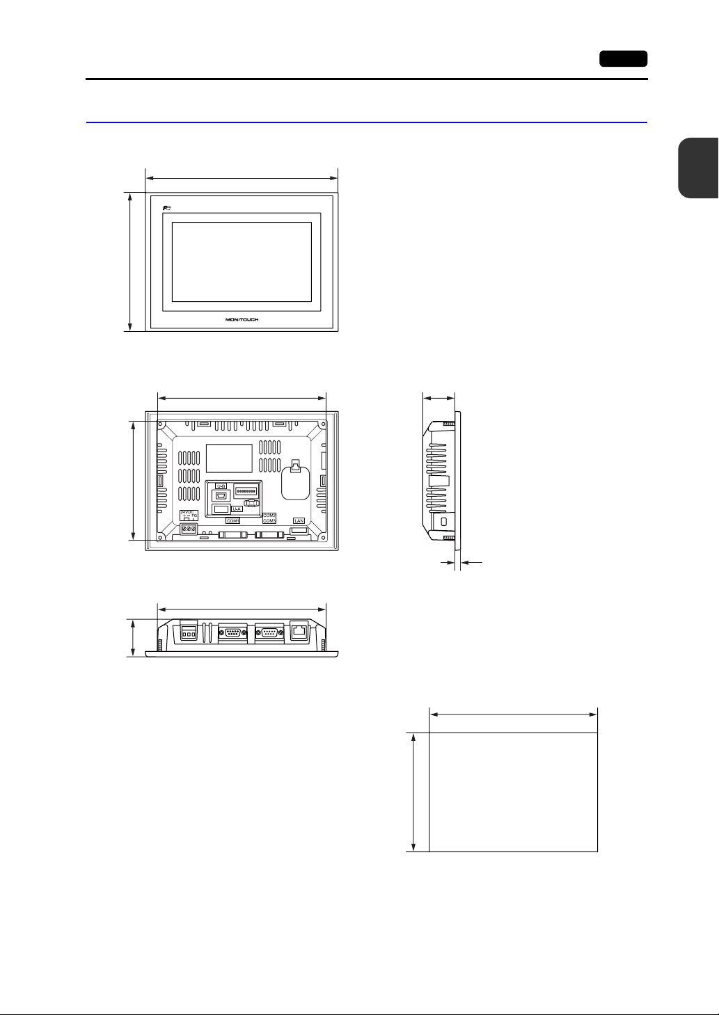
External Dimensions and Panel Cut-out Dimensions for TS1070
• Front View
155.0
• Rear View
133.0
215.0
188.0
(Unit: mm)
2
Specifications
• Side View
36.0
• Bottom View
42.0
188.0
6.0
• Panel Cut-out Dimensions
189.0
-0
+0.5
134.0
+0.5
-0
Page 25
2-8 3. Names and Functions of Components
3. Names and Functions of Components
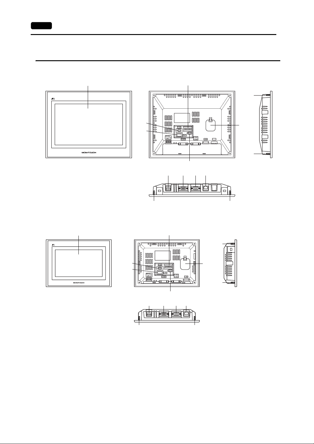
TS1100
1
2
11
TS1070
4
5
6
7
11
1
4
5
7
2
6
9 10
8
9 10
8
11
3
11
3
11
11
11
1. Display
This is the display unit.
2. DIP switches
Used to switch between RS-422 (4-wire connection) and RS-485 (2-wire connection) at COM1 or
setting the terminal resistance of the RS-422/RS-485 signal line at COM1 or COM3.
3. Battery holder
Contains a backup battery for SRAM and clock.
Replace the battery when its voltage has decreased.
4. USB-miniB (slave port)
Used for screen data transfer or connection with a PictBridge-compatible printer.
11
Page 26

3. Names and Functions of Components 2-9
5. USB-A (master port)
Used to connect a printer, a USB memory device, a USB CF card recorder USB-CFREC (optional
unit), a keyboard, or a mouse.
6. USB cable clamp hole
Used to attach a USB cable tie.
7. Power supply terminal block
Used for power supply (24 VDC) to the TS series.
8. RS-422/RS-485 communication connector (COM1)
Used to connect a controller (such as PLC, temperature controller, or inverter) via RS-422 (4-wire
connection) or RS-485 (2-wire connection).
9. RS-232C/RS-485 communication connector (COM2/COM3)
Used to connect a controller or a barcode reader via RS-232C or to connect a controller via
RS-485 (2-wire connection).
10. 100BASE-TX/10BASE-T connector (LAN) for TS1100i and TS1070i only
Used for Ethernet connection.
11. Mounting screws
Used to attach fixtures for securing the TS series to the mounting panel.
2
Specifications
Page 27
2-10 4. Serial Connector
4. Serial Connector
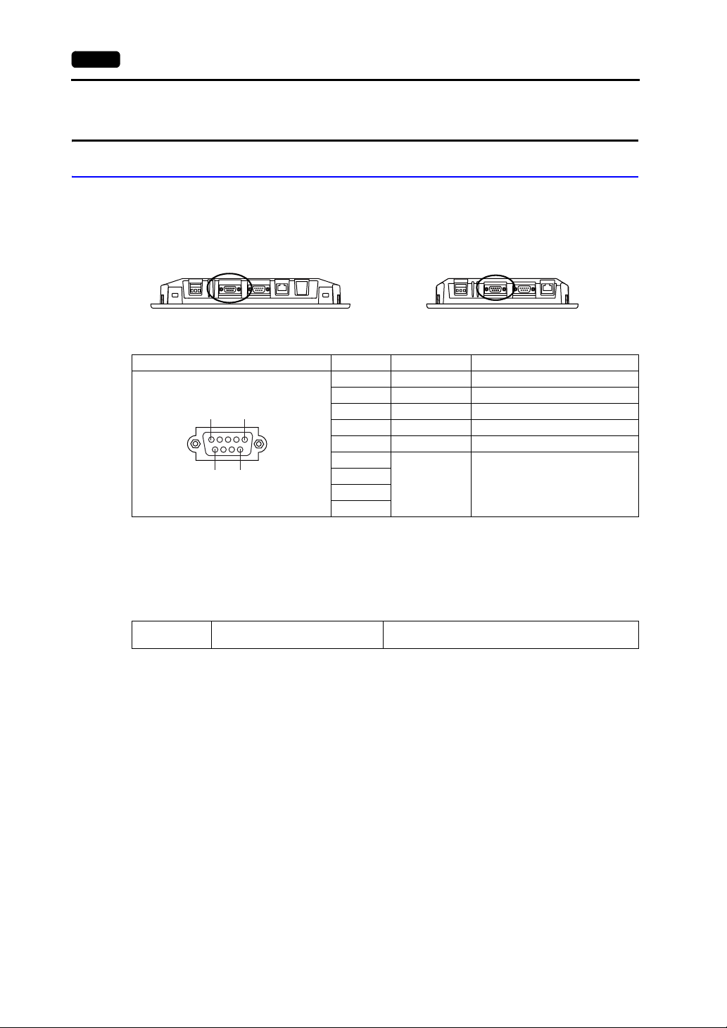
COM1: RS-422/485 Communication Connector
This connector is used to connect a controller via RS-422 (4-wire connection) or RS-485 (2-wire
connection).
• TS1100
Bottom view
• TS1070
Bottom view
The serial connector pins (COM1) correspond to signals as given below.
COM1 (D-sub 9-pin, female) Pin No. Signal Contents
1 +RD Receive data (+)
2 −RD Receive data (−)
5
1
6
9
* Use DIP switches 2 and 3 to switch between RS-422 (4-wire connection) and RS-485 (2-wire connection).
Setting the DIP switches 2 and 3 to ON connects +RD with +SD, and -RD with -SD in the TS unit.
For more information on DIP switches, refer to page 4-6.
3 −SD Send data (−)
4 +SD Send data (+)
5 SG Signal ground
6
7
8
9
NC Not used
Recommended Connector
The following connector is recommended for a self-made cable.
Recommended
connector
DDK’s 17JE-23090-02(D8C)-CG
D-sub 9-pin / male / inch screw thread (#4-40UNC) type
/ with hood / lead- and cadmium-free
Connection with PLC/Temperature Controller
The PLC or temperature controller can be connected.
For details on available models or settings on the V-SFT-5, refer to the TS Series Connection Manual.
Page 28
4. Serial Connector 2-11
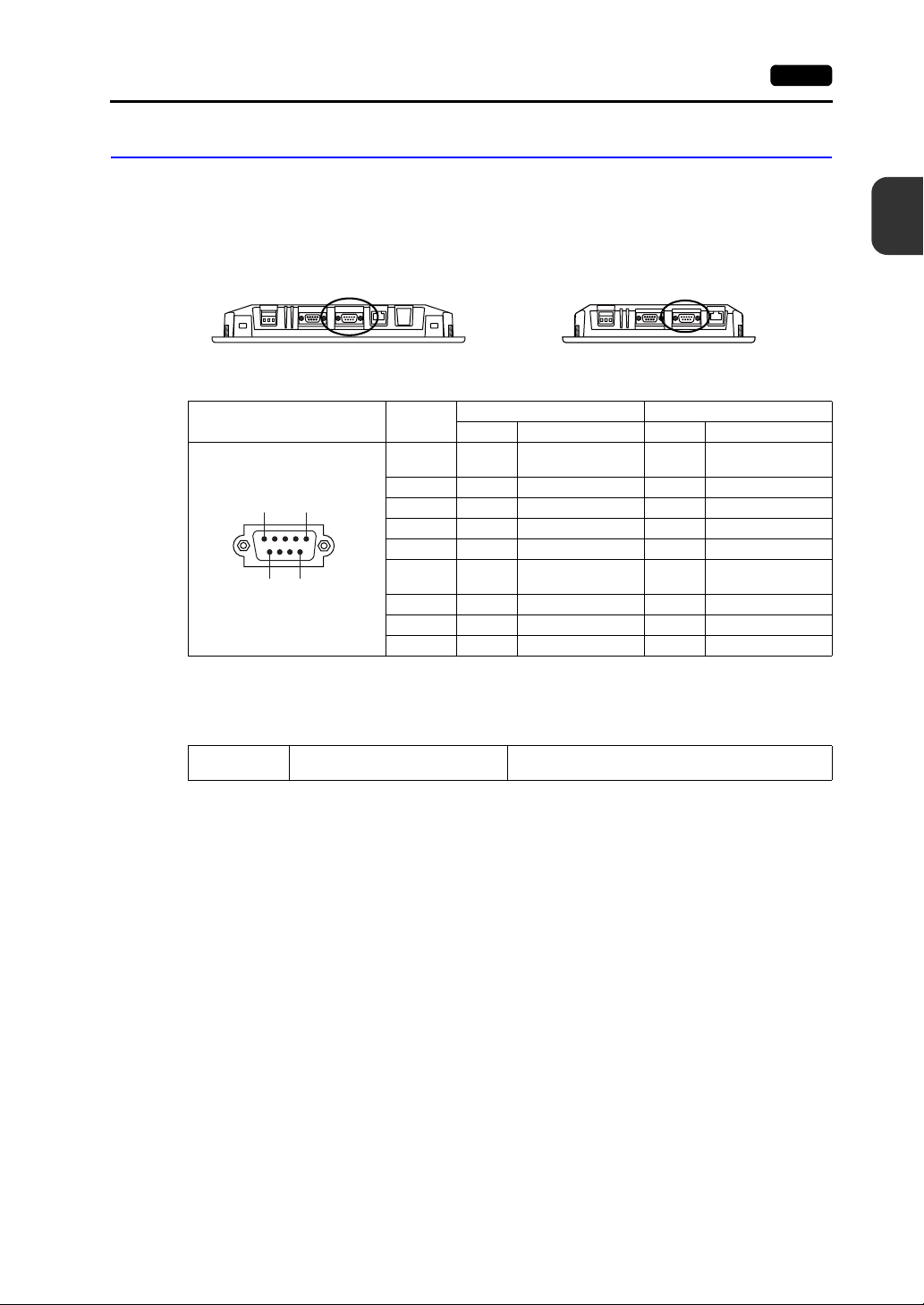
COM2: RS-232C/COM3:RS-485 Communication Connector
This connector is used to connect a controller or a barcode reader via RS-232C or to connect a
controller via RS-485 (2-wire connection).
Communicating via RS-232C (COM2) and RS-485 (COM3) can take place at the same time.
2
• TS1100
Bottom view
• TS1070
Bottom view
The serial connector pins (COM2/COM3) correspond to signals as given below.
COM2/COM3
(D-sub 9-pin, male)
1
5
9
6
Pin No.
1- - -SD/RD
2 RD Receive data - -
3 TD Send data - -
4 NC Not used - -
5 SG Signal ground - -
6- - +SD/RD
7 RTS Request to send - -
8 CTS Permission to send - -
9 - - SG Signal ground
RS-232C (COM2) RS-485 (COM3)
Signal Contents Signal Contents
Recommended Connector
The following connector is recommended for a self-made cable.
Recommended
connector
DDK’s 17JE-13090-02(D8C)A-CG
D-sub 9-pin / female / inch screw thread (#4-40UNC)
type / with hood / lead- and cadmium-free
Send/receive data
(-)
Send/receive data
(+)
Specifications
Connection with PLC/Temperature Controller
The PLC or temperature controller can be connected.
For details on available models or settings on the V-SFT-5, refer to the TS Series Connection Manual.
Connection with Barcode Reader
The barcode reader can be connected to read barcode data.
For details on settings on the V-SFT-5, refer to the TS Series Connection Manual.
Page 29

2-12 5. USB Connector
5. USB Connector
USB-A (Master Port)
This connector is used to connect a printer, a USB memory device, a USB-CFREC, a barcode reader,
a keyboard, a mouse, or a USB hub.
The USB-A port on the TS series complies with USB versions 2.0 and 1.1.
Printer
• TS1100
Rear view
• TS1070
Rear view
Enlarged view
By connecting a printer to the TS series, screen data, historical data, or data sheets can be printed out.
Connection Example
USB cable
*
TS
USB-A
* Use the cable included with the printer.
Available Printer
Model
PR-201
ESC-P
EPSON STYLUS PHOTO series
EPSON PX-V600/700
EPSON PX-V500
* For more information on available printers, visit our website (http://www.monitouch.com).
USB-to-parallel cable
UC-PGT (ELECOM) recommended
*
Port on the Printer Side Cable
Parallel port UC-PGT
Parallel port UC-PGT
USB-B USB cable
USB-B
Parallel port
Printer
Page 30
5. USB Connector 2-13
V-SFT-5 Setting
Click [System Setting] → [Device Connection Setting] → [Others] → [Printer]. In the tab window,
select [USB A] for [Connect to:] and a desired option for [Type].
USB Memory
By inserting a USB memory device (commercially available) into the TS series, the device can be used
for screen data transfer or historical data saving.
Connection Example
V-SFT-5 Setting
Notes on Handling the USB Memory
1. The TS series can recognize USB memory in FAT or FAT32 file systems.
2. Do not turn off the unit while the TS series is accessing the USB memory.
3. Make a backup copy of the USB memory at regular intervals.
4. If a disk error occurs and data read/write operation is disabled, execute ScanDisk on Windows and
5. The number of write cycles for a USB memory is limited. Consequently, frequent writing at short
6. When disconnecting the USB memory, open the Main Menu screen or hold down the [Storage
2
Specifications
TS
USB memory
USB-A
Click [System Setting] → [Storage Setting]. In the dialog, select [USB Port] for [Storage
Connection Target].
try to restore the device.
If not restored, format the device. Note that formatting will completely delete any stored data. (For
information on executing ScanDisk on Windows, refer to the manual for Windows.)
intervals may shorten the service life of the USB memory. When using USB memory to save
sampling data, be aware of the sampling time. Also, avoid repeated writing using a CYCLE macro
command.
Removal] switch on the screen.
Page 31

2-14 5. USB Connector
USB CF Card Recorder (USB-CFREC)
By connecting a USB-CFREC to the TS series, a CF card can be used for screen data transfer or
historical data saving.
Connection Example
TS
USB-A
USB-CFREC
V-SFT-5 Setting
Click [System Setting] → [Storage Setting]. In the dialog, select [USB Port] for [Storage
Connection Target].
Notes on Handling the CF Card
1. The TS series can recognize CF cards in FAT or FAT32 file systems.
2. Do not turn off the unit while the TS series is accessing the CF card.
3. Make a backup copy of the CF card at regular intervals.
4. If a disk error occurs and data read/write operation is disabled, execute ScanDisk on Windows and
try to restore the device.
If not restored, format the device. Note that formatting will completely delete the stored data. (For
information on executing ScanDisk on Windows, refer to the manual for Windows.)
5. The number of write cycles per CF card is limited (approx. 300,000 times). Consequently, frequent
writing at short intervals may shorten the service life of the CF card. When using a CF card to
save sampling data, be aware of the sampling time. Also, avoid repeated writing using a CYCLE
macro command.
6. When disconnecting the CF card, open the Main Menu screen or hold down the [Storage Removal]
switch on the screen.
7. When inserting a CF card, take care not to invert the card (make a distinction between its front and
back).
If a CF card is inserted upside down into the USB-CFREC, the card, the data stored on the card, or
the socket of the USB-CFREC may be damaged.
Page 32

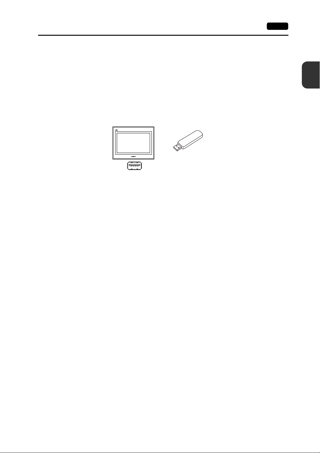
Barcode Reader
By connecting a barcode reader to the TS series, barcode data can be read through the barcode
reader.
5. USB Connector 2-15
Keyboard
Connection Example
TS
USB-A
4902580302447
Barcode reader
Available Barcode Reader
A USB-HID-compliant barcode reader can be connected.
For details on barcode readers of which operations have been verified, visit our website
(http://www.monitouch.com).
V-SFT-5 Setting
Click [System Setting] → [Device Connection Setting] → [PLC n: Barcode]. Select [USB A] for
[Connect to:]. In the [Communication Setting] tab window, select an option for [Type].
Numerals or characters can be entered by connecting a keyboard or a numeric keypad to the TS
series.
Connection Example
2
Specifications
Available Keyboard
Japanese keyboard 106 keyboard, 109 keyboard, etc.
US standard keyboard 101 keyboard, 104 keyboard, etc.
Numeric keypad
TS
USB-A
Type Re mark s
Keyboard
or
Numeric keypad
Page 33

2-16 5. USB Connector
V-SFT-5 Setting
An [Entry] icon must be registered on the screen where the keyboard is to be used.
In addition, numerical data or character display parts of [Display Function: Entry Target] are
required.
For more information, refer to the V8 Series Reference: Additional Functions.
TS Unit Setting
On the Main Menu screen, select a type of the keyboard to be connected.
For details, refer to “Keyboard Selection” page 5-37.
Mouse
By connecting a mouse to the TS series, the mouse can be used to operate screens displayed on the
unit.
Connection Example
TS
USB Hub
USB-A
For more information, refer to the V8 Series Reference: Additional Functions.
By connecting a USB hub to the TS series, devices like a printer or a USB-CFREC can be used at the
same time.
Mouse
Connection Example
TS
USB-B
USB-A
USB-CFREC
* A parallel printer can also be connected (on conditions that the model is available with the TS series and
connected with a commercially available parallel-to-USB cable (ELECOM’s UC-PGT recommended)). For
more information on available printer models, visit our website (http://www.monitouch.com).
USB-HUB
USB-B
Printer
*
Page 34

5. USB Connector 2-17
V-SFT-5 Setting
Refer to the previous “V-SFT-5 Setting”:
• Printer (page 2-12)
• USB Memory (page 2-13)
• USB CF Card Recorder (USB-CFREC) (page 2-14)
• Barcode Reader (page 2-15)
• Keyboard (page 2-15)
Notes
• A barcode reader and a keyboard cannot be connected to a USB hub at the same time.
• Two or more barcode readers or keyboards cannot be connected to a USB hub at the same time.
• A maximum of two USB hubs can be connected (cascaded) to the TS unit.
Note that performance will decrease when two USB hubs are connected.
• When a USB hub connected to the TS unit is powered through its accessory power supply
adaptor, do not turn off the adaptor or disconnect the connector between the adaptor and the USB
hub.
Doing so may cause insufficient power supply to the TS unit resulting in faulty operation such as
repeated restarting.
• When connecting two USB hubs to the TS unit, supply the power to each USB hub using its
accessory power supply adaptor.
Even when connecting only one USB hub, use its power supply adaptor (if the one is supplied with
a hub).
• Before disconnecting the USB memory device or the USB cable of the USB CF card recorder
USB-CFREC, open the Main Menu screen on the unit or hold down the [Storage Removal] switch
on the screen.
2
Specifications
Page 35

2-18 5. USB Connector
USB-miniB (Slave Port)
This connector is used for screen data transfer or connection with a PictBridge-compatible printer.
The USB-miniB port on the TS series complies with USB versions 2.0 and 1.1.
• TS1100
Printer (PictBridge)
Screen hard copy, historical data or data sheet can be printed out from the PictBridge-compatible
printer.
Connection Example
Rear view
• TS1070
Rear view
Enlarged view
Printer (PictBridge)
TS
USB cable
USB-miniB
* Use a commercially available USB cable. You are recommended to use a shielded twist-pair USB cable of
5 m in length.
*
PictBridge
USB-A
Available Printer
Any PictBridge-compatible printer can be connected.
V-SFT-5 Setting
Select [System Setting] → [Device Connection Setting] → [Others] → [Printer], and select
“PictBridge” for [Type] in the [Printer] tab window.
Page 36

Transferring Screen Data
Screen data can be transferred via USB-miniB (USB slave port).
Be sure to install the dedicated USB driver for the TS series on the computer. For the installation
procedure, refer to “Installation Procedure of the Driver for Screen Data Transfer” on (page 2-19).
Connection Example
TS
5. USB Connector 2-19
2
Specifications
USB cable
USB-miniB
*1 Use a commercially available USB cable. You are recommended to use a shielded twist-pair USB cable of
5 m in length.
*1
USB-A
Computer
Installation Procedure of the Driver for Screen Data Transfer
• For Windows Vista/7/8
1. Connect the USB-mini B port of the TS series (with power on) to the computer (with power on)
using a USB cable.
2. The USB driver is automatically installed. During installation, the following message is
displayed on the computer's taskbar.
3. The following message is displayed on the computer's taskbar when installation is finished.
If installation has terminated due to an error, reinstall the USB driver. See page 2-21.
- When successfully completed
- When terminated due to error
Page 37

2-20 5. USB Connector
• For Windows XP
1. Connect the USB-mini B port of the TS series (with power on) to the computer (with power on)
using a USB cable.
2. The message “Found New Hardware” and then the driver installation wizard appear on the
computer.
Select [No, not this time] and click the [Next] button.
3. Select [Install the software automatically (Recommended)] on the [Hardware Update Wizard]
and click [Next].
4. Installation of the USB driver starts.
Page 38

5. USB Connector 2-21
5. Click the [Finish] button on the screen below.
• For OSs earlier than Windows XP
For more information, refer to the V8 Series Operation Manual.
• When USB driver installation fails
If automatic installation of the USB driver fails, perform installation by the following procedure.
1. Open the following folder from [My Computer] or [Windows Explorer].
- For Windows Vista/7/8
C:\MONITOUCH\V-SFT V5\INF
- For Windows XP
C:\Program Files\V-SFT V5\INF
2. Double-click "V-SFTV5_USBDriver.exe".
2
Specifications
Depending on your computer, the following dialog may be displayed when using Windows Vista/7/8.
Click the [Yes] button.
Page 39

2-22 5. USB Connector
3. Click the [Next] button on the screen below. Installation of the USB driver starts.
4. Click the [Finish] button on the screen below.
USB driver installation is complete.
Recognition of USB Driver
When the driver has been installed successfully, the [Device Manager] window shows “Operation
Panel - Operation Panel USB Driver”.
• For Windows Vista/7/8 • For Windows XP
This will disappear when MONITOUCH and computer are disconnected.
If [Other Device] or a mark other than shown above is displayed even while the USB is connected, the
USB driver is not recognized. If this happens, uninstall the USB driver and reinstall it.
Page 40

Securing USB Cables
A USB cable may be disconnected from the TS unit depending on the mounting condition.
Using the cable tie supplied with the unit should prevent such a problem.
Securing the USB Cable
1. Preparing a cable tie
Draw a cable tie through the hole as shown in the figure below.
2. Inserting and securing a USB cable
Insert a USB cable and secure it using the cable tie.
5. USB Connector 2-23
2
Specifications
The following figures show cases where only USB-miniB is used and where both USB-A and
USB-miniB are used.
When only USB-miniB port is used:
When both USB-A and USB-miniB (two cables) are
used:
Page 41

2-24 5. USB Connector
Space for USB Connectors Behind the Unit
On the TS series, ports to connect USB cables or USB memory are provided on its backside.
Because of this design, space is needed behind the unit.
To allow connection of USB cables or USB memory, leave 150.0 mm (or more) of space to the rear of
the TS unit.
Example: A USB cable (with ferrite core) connected
150.0 mm or more
(recommended)
Page 42

6. LAN Connector (TS1100i/TS1070i Only) 2-25
6. LAN Connector (TS1100i/TS1070i Only)
LAN Connector
This connector is used to connect a controller via Ethernet.
The LAN connector supports 100BASE-TX/10BASE-T.
• TS1100
The LAN connector pins correspond to signals as given below.
Specification: IEEE802.3 (u)-compliant, supporting UDP/IP, TCP/IP, and Auto-MDIX
The LAN connector is associated with LEDs as given below.
Green LED Orange LED
• TS1070
Bottom view
LAN Pin No. Signal Contents
1 TX+ Ethernet send signal (+)
2TX− Ethernet send signal (−)
3 RX+ Ethernet receive signal (+)
4 NC Not used
5 NC Not used
6RX− Ethernet receive signal (−)
8 76 5 43 21
LAN
LED Status
Green Orange
ON ON Connected via 100 BASE-TX
7 NC Not used
8 NC Not used
Bottom view
2
Specifications
Contents
Wiring
CAUTION
ON OFF Connected via 10 BASE-T
Blinking ON/OFF Sending/receiving data
When using the LAN port, keep the LAN cable away from the power supply cable as
much as possible.
Use a commercially available cable. Using a self-made cable may cause an error in network
connection.
Recommended cable: 100 Ω UTP (unshielded twist-pair) cable, category 5, max. 100 m long
* Both straight and cross cables are usable, irrespective of the presence or absence of a hub.
Page 43

2-26 6. LAN Connector (TS1100i/TS1070i Only)
Please use this page freely.
Page 44

3
1. Mounting Procedure
2. Power Supply Cable Connection
Installation
Page 45

1. Mounting Procedure
Mounting Procedure
1. Insert the TS unit into the mounting panel (max. thick: 5 mm).
* When using an optional waterproof gasket “TS1xx0-WP”, firmly sandwich the gasket between
the mounting panel and the TS series.
Panel cut-out hole
X
Y
Mounting panel
1. Mounting Procedure 3-1
Panel cut-out dimensions
X
+0.5
TS1100
TS1070
257.0
189.0
-0
+0.5
-0
X
Y
199.0
134.0
YModel
+0.5
-0
+0.5
-0
Unit: mm
3
Installation
2. Fit the supplied four fixtures onto the screws of the TS series. Tighten them with the supplied four
nuts. (Tightening torque: 0.3 to 0.4 N•m)
* When the TS unit is attached to the mounting panel, the fixtures and frame grounds (FG) are
connected.
Screw
Mounting panel
• Nut dimensions
8
14.0
•Fixture
dimensions
4.2
17.5
• Dimensions of a tightened fixture that lies off the edges of the
TS unit
17.5
8.5
Fixture
Nut
(Unit: mm)
8.5
Back of the TS unit
Page 46

3-2 1. Mounting Procedure
Mounting Angle
Install the unit within the angle of 15° to 135° as shown below.
90q
135q
D
i
s
p
l
a
y
y
a
l
p
s
i
D
15q
0q
Page 47

2. Power Supply Cable Connection 3-3
2. Power Supply Cable Connection
DANGER
Electric shock hazard
Shut the power off before connecting the power supply cable.
Power Supply Cable Connection
Connect the power supply cable to the terminal on the backside of the unit.
Cable Specifications
For information on the tightening torque of the screws on the terminal block, refer to the following table.
Tightening Torque 0.5 to 0.6 N•m (5 to 6 kgf•cm)
Recommended Screwdriver SZS 0.6 × 3.5 (Phoenix Contact)
When Using Bare Cables
• Do not solder the end sections of power cable wires. Soldering may result in bad
electrical contacts.
CAUTION
• When using stranded wire for the power cable, make sure the strands are
sufficiently twisted.
Failure to do so may cause shorting between stray strands or adjacent electrodes.
Power supply
24 VDC ± 10 %
3
Installation
Grounding
Cable Size
Wire Length
Power supply cable: AWG 18 to AWG 14, twisted/single (1.0 to 1.6 mm diameter)
Frame ground (FG): AWG 20 to AWG 14, twisted/single (0.8 to 1.6 mm diameter)
6.5 mm
When Using Ferrules
AI 0.75-6 GY
Recommended Ferrule (Pin type)* Phoenix Contact
Recommended Crimping Tool Phoenix Contact CRIMPFOX 6
* Select a ferrule according to the cross section area (diameter) of the power cable.
AI 1-6 RD
AI 1.5-6 BK
Page 48

3-4 2. Power Supply Cable Connection
Power Supply Cable Connection
Avoid applying excessive force to the power supply cable. This may lead to
DANGER
unintentional disconnection of the cable and cause serious accidents such as electric
shock.
• The power source must be within the allowable voltage fluctuation.
• Use a power source with low noise between the cables or between the ground and the cable.
• Use the thickest power supply cable possible to minimize drops in voltage, and twist.
• Keep power supply cables away from high-voltage, large-current carrying cables.
Grounding
CAUTION
Be sure to establish a ground of the TS Series.
(The level of grounding resistance should be less than 100 Ω.)
• An independent earth pole must be used for the TS Series.
• Use AWG20 to AWG14 size wiring for the grounding cable.
• Set the grounding point near the TS Series to shorten the distance of grounding cables.
Independent grounding (best) Shared grounding (good) Cross grounding (prohibited)
TS unit
D class grounding
(ground resistance
of 100 Ω or less)
Other
equipment
TS unit
D class grounding (ground
resistance of 100 Ω or less)
Other
equipment
TS unit
Other
equipment
Page 49

4
1. Coin-type Lithium Battery
2. DIP Switches
Handling of
TS Series
Components
Page 50

1. Coin-type Lithium Battery
1. Coin-type Lithium Battery 4-1
CAUTION
The battery is inserted upon delivery.
Battery Usage
This battery for memory backup is used for the user memory area in SRAM (non-volatile memory $L
and $LD, sampling data) and the built-in clock.
Time for Battery Replacement
The battery validity period is about thee years after the date of manufacture.
When the time to replace the battery is approaching, the [Press this switch after battery replacement.]
switch and the message “Battery changeover required” appear at the bottom of the Main Menu screen
on the TS unit.
* For more information about the Main Menu screen, refer to “Main Menu Screen” (page 5-3).
4
Handling of TS Series Components
Main Menu screen
Battery Replacement
Recommended Battery
Recommended battery manufacturers and battery model are as follows:
Recommended Manufacturer Model
Mitsubishi Electric Home
Appliance
Hitachi Maxell
Panasonic
FDK
CR2032 Coin-type lithium primary cell
Page 51

4-2 1. Coin-type Lithium Battery
Safety Instructions on Handling the Battery
Lithium batteries contain combustible material such as lithium or organic solvents. Mishandling may
cause heat, explosion or ignition resulting in fire or injury. To prevent accidents, pay attention to the
following cautions when handling lithium batteries.
CAUTION
• Be sure to discharge static electricity from your body before battery replacement.
• Use the recommended battery for replacement.
• Rough handling of the battery may cause fire or chemical burn hazard.
• Do not disassemble, incinerate or heat the battery.
• Observe local and governmental regulations when disposing of waste batteries.
• Keep batteries out of reach of children. (If swallowed, immediately consult a doctor.)
• Never re-charge the battery.
• If the battery leaks or smells, the leaking battery electrolyte is flammable. Keep
from heat or flame.
SRAM Area Backup Procedure
Before replacing the battery, be sure to make a backup copy of data stored in SRAM using the
V-SFT-5 editor.
When Using the V-SFT-5 Editor:
1) Connecting a USB cable
Connect the TS unit and the computer with a USB cable.
2) Starting the V-SFT-5 editor
Start the V-SFT-5 editor on the computer.
3) Displaying the [Transfer] dialog
Click the [Transfer] icon. The [Transfer] dialog is displayed.
4) Selecting data to be transferred
Select [Transfer Device: Display] and [Transfer Data: SRAM Data].
Do not check [ Use Simulator].
5) Starting SRAM data transfer
Click the [PC <−] button under [Transfer]. Data transfer from the SRAM is started.
6) Saving the SRAM data
When the SRAM data has been transferred, the [Save As] dialog is displayed on the
computer. Save the data as a backup copy. The extension is “∗.RAM”.
* To transfer the “∗.RAM” data saved as a backup to the TS unit, click the [PC −>] button
under [Transfer] in step 5.
When Using Storage:
For backing up data to storage such as a USB memory, refer to “Saving Backup Copies of
SRAM” (page 5-24).
Page 52

Battery Replacement Procedure
1. Coin-type Lithium Battery 4-3
DANGER
1. Make a backup copy of data stored in the SRAM area.
For backing up procedure, refer to “SRAM Area Backup Procedure” (page 4-2).
2. Turn off the TS unit.
3. Lift and remove the cover of the battery holder according to the arrows marked in the figures
below.
Example: TS1070
4. Press the detent on the right of the battery in the direction of the arrow.
Electric shock hazard
Turn off the power to the TS series before performing steps 3 through 7 below.
Rear view
4
Handling of TS Series Components
Detent
Battery
5. When the right side of the battery rises, insert a finger under the battery as indicated by the arrow
and take it out.
6. Slide a new battery with the “+” side of facing upward, to the left into the battery holder. Press the
right side of the battery until it clicks.
Page 53

4-4 1. Coin-type Lithium Battery
7. Insert the detent on the underside of the battery holder cover into the TS unit. Press the top of the
cover until it clicks.
8. Turn on the TS unit. Go to the Main Menu screen and press the [Press this switch after battery
replacement.] switch.
The following confirmation dialog appears. Press [Completed].
* If not replacing with a new battery, press [Cancel].
If the [Completed] switch is pressed though no new battery is set, no power will be
CAUTION
supplied to retain the clock time and SRAM.
Finish replacing with a new battery before pressing [Completed].
9. Check that the [Press this switch after battery replacement.] switch and the message “Battery
changeover required” are cleared from the bottom of the Main Menu screen.
10. When a backup file “∗.RAM” is saved, transfer it to the TS series.
Page 54

Notes on Battery: EU Directive 2006/66/EC
According to the EU directive 2006/66/EC effective in EU countries, the battery supplied with the TS
series as well as the package box of the TS series have the marking shown below:
1. Coin-type Lithium Battery 4-5
CAUTION
• The marking shown above is effective only in EU countries.
• The details on the marking are designated in Article 20 “Information for end-users”
and ANNEX II in EU directive 2006/66/EC.
• The marking indicates that the battery should be disposed of separately from
general household waste.
• If element symbols are indicated below the marking, it means that the battery
contains the specified heavy metal at a concentration exceeding the control value.
See the following for the control values of concentration.
Hg: mercury (0.0005 %), Cd: cadmium (0.002 %), Pb: lead (0.004 %)
• The EU has determined the separating program for used batteries.
Dispose of used batteries properly at your local waste-disposal/recycling center.
4
Handling of TS Series Components
Page 55

4-6 2. DIP Switches
2. DIP Switches
DIP Switch (DIPSW) Setting
The TS series is equipped with DIP switches 1 to 8. When setting the DIP switches, turn the power off.
TS1100
Rear view
DIP switch setting upon delivery
ON
12345678
Storage automatic upload
COM1 4-wire → 2-wire (+) switch
COM1 4-wire → 2-wire (-) switch
PPI/MPI terminating resistance (-RD/SG)
TS1070
Rear view
DIP switches
Enlarged view
COM3 terminating resistance
+RD/-RD terminating resistance of COM1
+SD/-SD terminating resistance of COM1
PPI/MPI terminating resistance (+RD/+5V)
Page 56

2. DIP Switches 4-7
DIPSW1* (Storage automatic upload)
Set the DIPSW1 to ON when automatically uploading screen data from storage such as a USB
memory.
Procedure
1. Preparation of storage
Prepare storage such as a USB memory with screen data written from V-SFT-5. (For the loading
procedure, refer to the V8 Series Reference Manual.)
2. Connection of storage
Turn off the TS unit. Connect the storage device to the USB-A port.
3. DIP switch setting
Slide the DIPSW1 to ON.
4. Automatic upload start
Turn on the TS unit. Screen data is automatically loaded into the flash memory of the TS unit.
* Be sure to set the DIPSW1 to OFF when automatic upload is not performed.
DIPSW2 and DIPSW3 (COM1 switching between 4-wire and 2-wire)
• When connecting a controller to COM1 via RS-422/485 (2-wire connection), set the DIPSW2 and
DIPSW3 to ON.
• When connecting a controller to COM1 via RS-422/485 (4-wire connection), set the DIPSW2 and
DIPSW3 to OFF.
4
Handling of TS Series Components
DIPSW4 and DIPSW5 (PPI/MPI terminating resistance setting)
When connecting a Siemens PLC (PPI/MPI) to COM1, set the DIPSW4 and DIPSW5 to ON.
DIPSW6, DIPSW7, and DIPSW8 (terminating resistance setting)
• When connecting a controller to COM1 via RS-422/485 (2-wire connection), set the DIPSW7 to
ON.
• When connecting a controller to COM1 via RS-422/485 (4-wire connection), set the DIPSW6 and
DIPSW7 to ON.
• When connecting a controller to COM3 via RS-422/485 (2-wire connection), set the DIPSW8 to
ON.
Page 57

4-8 2. DIP Switches
Please use this page freely.
Page 58

5
1. Before Operation
2. Main Menu Screen
3. System Menu
TS Series
Operations
Page 59

1. Before Operation
Procedure before Operation
1. Mount the TS series on the mounting panel, install it and carry out wiring.
For more information, refer to “Chapter 3 ”.
2. Install peripheral devices, such as PLCs or temperature controllers, and carry out wiring.
For information on precautions, refer to the TS series Connection Manual separately provided.
3. Turn the TS series on.
When turning the power on for the first time: Other cases:
1. Before Operation 5-1
5
&CVC.QCFKPI
4. Transfer the created screen data.
• When transferring screen data for the first time:
For details, refer to “Transferring Screen Data to TS Series for the First Time” (page 5-2).
• Other cases:
For information on the procedure to change screen data with another, refer to the V8 series
Operation Manual.
5. Start MONITOUCH operation. To change to the RUN mode, refer to “Main Menu Screen” (page
5-3).
When the connection with controllers has been established, the RUN screen is displayed.
* If MONITOUCH does not operate normally and shows an error message, eliminate the cause
by referring to Chapter 6 or the V8 Series Reference Manual.
TS Series Operations
Page 60

5-2 1. Before Operation
Transferring Screen Data to TS Series for the First Time
There are four methods for transferring screen data for the first time after purchase.
Initial screen displayed when the power is turned on for the first time
IP address setting
for the TS
Displays the
Storage Transfer
screen.
USB memory
or
USB-CFREC
Ethernet
USB
LAN
USB-miniB
USB-A
Displays communication status between the TS and the computer.
1) Transfer via USB
Connect a USB cable to the USB slave port (USB-miniB) on the TS series, and transfer screen
data from the computer.
2) Transfer from storage
Use a USB memory device or an optional USB-CFREC with a CF
card.
Load screen data from the computer into storage in advance.
Press the [Storage (English)] switch on the initial screen. The
Storage Transfer screen is displayed. Data transfer can be performed on the screen.
3) Transfer from storage (automatic upload)
Load screen data from the computer to the storage device (e.g. USB memory) in advance.
When the power to MONITOUCH is turned on, screen data transfer is automatically started.
4) Transfer via Ethernet (TS1100i/TS1070i only)
Connect an Ethernet cable to the LAN port on the TS series, and
transfer screen data from the computer.
Pressing the [IP Address (English)] switch on the initial screen
brings up the Ethernet screen. Set the IP address for the TS series on the screen.
When the screen data has been transferred, the following screen is brought up. For details, refer
to “Main Menu Screen” (page 5-3).
Main Menu screen after screen data is transferred
Page 61

2. Main Menu Screen
Displaying the Main Menu Screen
2. Main Menu Screen 5-3
To bring up the Main Menu screen in the RUN mode, press the corners on the TS series unit and the
[MODE] switch on the System Menu
Recognition area
* For the details on the System Menu, refer to “System Menu” (page 5-43).
1. Hold down any corner for two seconds or longer, and remove your finger.
2 cm
2 cm
*
.
2 cm
2 cm
2 cm
2 cm
2 cm
2 cm
Recognition area
5
TS Series Operations
Hold down the upper left corner for two second or longer.
2. Hold down one of the other three corners for two seconds or longer. Then the System Menu is
displayed.
Hold down one of the other three corners for two second or longer.
* When an item, such as a switch, data display part with switch, display area, slider switch, scroll bar, or table data
display part, is placed on the position you press, the switch in the recognition area becomes invalid. Press a
corner where none of the items described above is placed. If the items are placed on all of the corners, change
the screen to another and display the Main Menu screen by following the procedure described above.
System Menu
Page 62

5-4 2. Main Menu Screen
3. Press the [MODE] switch while the System Menu is displayed. Then the Main Menu screen is
displayed.
Main Menu Screen
The Main Menu screen indicates the TS series model, system information, and screen data
information.
Also, it works as the system screen when the screen data is transferred between a computer and the
TS series.
Main Menu screen
[Main Menu] switch
Screen data file comment,
total amount of memory
occupied by the screen data
System program version
Font version
Ethernet information
(on TS1100i/TS1070i only)
Port used for screen data transfer
Model
Error/warning (at the time of occurrence)
Clock
Controller and version of
the I/F driver specified for
the screen data file
Page 63

[Main Menu] Switch
Pressing the [Main Menu] switch brings up the following drop-down window.
Main Menu screen
Main Menu Screen Composition
2. Main Menu Screen 5-5
Main Menu drop-down window
5
TS Series Operations
The Main Menu screen is configured as shown below:
Main Menu
screen
[Main Menu]
switch
Extended Function Setting screen
Hold down the [Editor : USB] switch at the bottom left corner of the Main
Menu screen for three seconds or longer.
For more information, refer to “Extended Function Setting” (page 5-41).
[RUN] switch (refer to page 5-6.)
[Language] switch (refer to page 5-6.)
[Comm. Parameter] switch (refer to page 5-7.)
[Ethernet] switch (on TS1100i/TS1070i only)(refer to page 5-8.)
[SRAM/Clock] switch (refer to page 5-12.)
[Extension Program Info.] switch (refer to page 5-14.)
[Storage Transfer] switch (refer to page 5-15.)
[Bright Adjustment] switch (refer to page 5-28.)
[I/O Test] switch (refer to page 5-29.)
[Print Check] switch (refer to page 5-34.)
[Switch Check] switch (refer to page 5-35.)
[Keyboard] switch (refer to page 5-35.)
For more information on the [Simulator] switch, refer to the
V8 Series Operation Manual.
[Extended Setting] switch (on TS1100i/TS1070i only)
(refer to page 5-41.)
Page 64

5-6 2. Main Menu Screen
1. RUN
Pressing the [RUN] switch on the Main Menu drop-down window switches the screen to the RUN
mode.
Main Menu drop-down window
RUN screen
&CVC.QCFKPI
2. Language Selection
Pressing the [Language] switch on the Main Menu drop-down window brings up the Language
Selection screen.
Languages* selected in the [Font Setting] dialog of the V-SFT-5 editor are displayed on the Language
Selection screen that is used for selecting an interface language for the Main Menu screen.
Main Menu drop-down window
Language Selection screen
* The interface language for the Main Menu screen can be selected from English, Japanese, Chinese (Simplified),
Chinese (Traditional) or Korean. English is always displayed.
Page 65

3. Communication Parameter
Pressing the [Comm. Parameter] switch on the Main Menu drop-down window brings up the Comm.
Param. screen.
Communication parameters of PLC1 to PLC8 that are set on the V-SFT-5 editor can be checked on
this screen.
Main Menu drop-down window
2. Main Menu Screen 5-7
5
TS Series Operations
Displays a specified
communication
parameter.
Comm. Param. screen
Moves back to the
Main Menu screen.
Changes the display
of the setting
between PLC1 to
PLC8.
Page 66

5-8 2. Main Menu Screen
4. Ethernet (TS1100i/TS1070i Only)
Pressing the [Ethernet] switch on the Main Menu drop-down window brings up the Ethernet screen.
This screen is used to set an IP address for the TS unit.
Main Menu drop-down window
Ethernet screen
Switches between [IP
Address Setting] and
[Select IP Address from
Network Table].
Indicates whether the LAN port works correctly with an Ethernet cable inserted.
Normal: Connect (white)
Abnormal: Disconnect (gray)
*1 *2
*1 For more information, refer to the TS Series Connection Manual.
*2 This switch is not displayed if [IP Address Setting] (page 5-10) is set using V-SFT editor.
Moves back to the
Main Menu screen
or the initial screen.
Displays the keypad
for IP address
setting.
When making the setting, press the [Setting
Finished] switch to determine the setting.
The Main Menu screen is displayed.
Page 67

4-1. IP Address Setting for the TS Series
For communicating via Ethernet, set the IP address for the TS unit. An IP address can be set either on
the TS unit or in screen data using the V-SFT editor.
Setting on the TS Unit
1. Press the [Ethernet] switch on the Main Menu drop-down window to display the Ethernet screen.
2. Press the [EDIT] switch and set each item.
Before change
It is not used when the gateway or the subnet mask is zero.
3. Press the [Setting Finished] switch to determine the IP address. Check the IP address displayed
under [Ethernet Information] on the Main Menu screen.
2. Main Menu Screen 5-9
Change the IP address using the keypad.
5
TS Series Operations
Determine the IP address setting.
Page 68

5-10 2. Main Menu Screen
Setting using the V-SFT Editor
1. Select [System Setting] → [Ethernet Communication] → [Local Port IP Address] on the V-SFT
editor. The [IP Address Setting] dialog is displayed.
2. Check the [Set IP] check box and set each item.
Select IP Address from
Network Table
IP Address
Send Timeout
Retrials
Memory Protect
* For more information on setting items, refer to page 5-11.
*
Default Gateway
Subnet Mask
Port No.
Internal Memory
Memory Card Memory
*
*
*
This is valid when the IP address of the TS has been registered in the
network table. Select a network table number from 0 to 99 to set the IP
address.
Set the IP address for the TS.
Set the default gateway.
Set the subnet mask.
When this box is not checked, the subnet mask is automatically assigned
based on the byte at the extreme left of the IP address.
Example:
IP address 172.16.200.185: “255.255.0.0” is set.
IP address 192.168.1.185: “255.255.255.0” is set.
Set a port No. 1024 to 65535, except for 8001.
Set a timeout period for transmitting macro commands SEND, EREAD or
EWRITE, or macro commands for MES.
0 to 255
Set the number of retrials to be performed when a time-out occurs.
Check either check box to write-protect the memory from computers or
other stations.
3. Click [OK].
4. Transfer the screen data to the TS unit. Check the IP address displayed under [Ethernet
Information] on the Main Menu screen.
Page 69

2. Main Menu Screen 5-11
IP Address
This is an address that is used for recognizing each node on the Ethernet and should be unique.
The IP address is 32-bit data which consists of the network address and the host address and can be classified
into A to C depending on the network size.
Class A
Class B
Class C
Notation
A string of 32-bit data is divided into four, and each segment delimited with a period is in decimal notation.
Example: The IP address in class C shown below is represented as “192.128.1.50”.
<Unusable IP addresses>
• “0” is specified for one byte at the extreme left. Example: 0.x.x.x
• “127” is specified for one byte at the extreme left (loop back address). Example: 127.x.x.x
• “224” or more is specified for one byte at the extreme left (for multi-cast or experiment). Example: 224.x.x.x
• The host address consists of only “0” or “255” (broadcast address). Example: 128.0.255.255, 192.168.1.0
Port Number
Multiple applications are running on each node, and communications are carried out for each application between
the nodes. Consequently, it is necessary to have a means to identify the application that data should be
transferred to. The port number works as this identifier. Each port number is 16-bit data (from 0 to 65535).
The TS series uses ports for screen data transfer (8001), PLC communication (as desired), and the simulator
(8020). Set a unique number in the range of 1024 to 65535. For a PLC or a computer, set the port number in the
range of 256 to 65535. It is recommended to set a greater number.
11000000 10000000 00000001 00110010
Network address
0
(7)
10
110
Host address (24)
Network address (14) Host address (16)
Network address (14)
Host address (8)
5
TS Series Operations
Default Gateway
A gateway and a router are used for communication between different networks.
The IP address of the gateway (router) should be set to communicate with the node(s) on other networks.
Subnet Mask
A subnet mask is used for dividing one network address into multiple networks (subnet).
The subnet is assigned by specifying a part of the host address in the IP address as a subnet address.
Class B
Subnet mask
<Unusable subnet masks>
• All bits are set to “0”. 0.0.0.0
• All bits are set to “1”. 255.255.255.255
10
Network address (14)
255. 255.
11111111
Network address Subnet address
11111111 11111111 00000000
Host address (16)
255.
Host address
0
Page 70

5-12 2. Main Menu Screen
5. SRAM/Clock
Pressing the [SRAM/Clock] switch on the Main Menu drop-down window brings up the SRAM/Clock
screen.
This screen is used for correcting the built-in calendar (date and time) and for formatting the SRAM
area.
Main Menu drop-down window
Formats an SRAM area.
*1 Be sure to replace the battery. SRAM and clock time cannot be retained without battery power.
For replacing the battery, refer to “Coin-type Lithium Battery” (page 4-1).
SRAM/Clock screen
Moves back to the
Main Menu screen.
Determines the
changed date and
time.
[←] / [→] switch:
moves the cursor.
[+] / [−] switch:
corrects the date and
time.
Displayed when the time for battery replacement is approaching.
*1
Page 71

5-1. Date and Time Adjustment
This screen is used for correcting the built-in clock of the TS series.
To use the built-in clock of the TS series, check [Use Built-in Clock] in the [SRAM/Clock Setting] dialog
that is displayed by selecting [System Setting] → [Unit Setting] → [SRAM/Clock] on the V-SFT-5 editor.
1. Move the cursor using the [←] and [→] switches. Correct the date and time using the [+] and [−]
switches.
2. Press the [Set] switch to determine the setting. The clock displayed on the upper right is modified.
2. Main Menu Screen 5-13
Before change
3. Pressing the [Return] switch displays the Main Menu screen again.
5-2. Formatting SRAM
An SRAM area can be formatted.
When the SRAM area is formatted, the contained data (historical data saved in SRAM, internal
memory $L, etc.) is cleared. Double-check before formatting the SRAM.
1. Press the [Format] switch and the [Execute] switch.
The SRAM area is formatted in the current screen data format. When formatting has been
completed, the message “∗∗Format Completed∗∗” is displayed.
Before formatting the SRAM area
After change
5
TS Series Operations
Format of the SRAM area completed
2. Pressing the [Return] switch displays the Main Menu screen again.
Page 72

5-14 2. Main Menu Screen
n
6. Extension Program Information
Pressing the [Extension Program Info.] switch on the Main Menu drop-down window brings up the
Extension Program Info. screen. This screen is used for checking program versions of the ladder
transfer function, simulator, etc.
Main Menu drop-down window
Extension Program Info. screen
Moves back to the Mai
Menu screen.
Changes the page of
the extension program
information.
Displays the
extension program
information.
Page 73

7. Storage Transfer
Pressing the [Storage Transfer] switch on the Main Menu drop-down window brings up the Storage
Transfer screen.
This screen is used to transfer screen data between the TS series and a USB memory device or a CF
card (with an optional USB-CFREC).
Main Menu drop-down window
2. Main Menu Screen 5-15
5
TS Series Operations
Storage Transfer screen
Moves back to the
Main Menu screen or
the initial screen.
1.
1. [Data Selection] field
• [Screen Data]
Press this switch when transferring screen data to/from storage.
• [SRAM]
Press this switch when backing up data from the SRAM in the TS series to a storage device
before battery replacement or when uploading from a storage device to the SRAM.
2.
Page 74

5-16 2. Main Menu Screen
2. [Transfer Menu] field
• [Display <--- Storage]
Press this switch when transferring data from a storage device to the TS series.
• [Display---> Storage]
Press this switch when transferring data from the TS series to a storage device.
• [Display <--> Storage]
Press this switch when comparing stored data between the TS series and a storage device.
• [Delete]
Press this switch when deleting data from storage.
Page 75

2. Main Menu Screen 5-17
7-1. Storage Folder Configuration
The table below lists the folders in storage, the files in the folders, and the contained data.
For more information, refer to the V8 Series Reference Manual.
Storage (USB memory/CF card)
DAT0000 (Access folder name: User-definable within 32 one-byte characters)
Folder Name
(fixed)
BITMAP Pattern (bitmap) data BMPxxxx.BIN TS ← Storage
CARD
DSP Screen data DSP0000.BIN TS ↔ Sto ra ge
FONT Gothic fonts or language data xxxxxx.FTD TS ← Storage
HDCOPY
JPEG JPEG file (except for some models)
LADDER
MEMO Memo pad data MEMxxxx.BIN
MSG Message file
OPELOG
RECIPE
SAMPLE
SCRN
SRAM Backup copy of SRAM SRM0000.BIN TS ↔ Storage
WEBSERV Files to be accessed from the Web browser *.SHT, *.HTML, *.TXT etc. TS ← Storage
Recipe data using the V6-compatible memory
manager function
Hard copy image
(JPEG/BIN format selectable for 128-color display)
Ladder data associated with the ladder monitor function
Operation log file
Recipe data
Data of data logging and alarm history
Title file SMHxxxx.CSV TS ← Storage
Header file SCHEADER.BIN
Screen file
Component parts (macro blocks, sampling messages)
3D parts file 3Dxxxx.BIN
Windows font file (graphics, messages)
*1
Contents File Name
MCMHEAD.BIN
MCMxxxx.BIN
HDxxxx.JPG
*1
HDxxxx.BIN
xxxxx.JPG
JPxxxxx.JPG
*2
MSGxxyyy.BIN
MSGxxyyy.TXT
*3
OPELOG_hhmmss.BIN TS ↔ Stor ag e
RECxxxx.CSV
xxxxxxxx.CSV
SMPxxxx.BIN
SMPxxxx.CSV
SCxxxx.BIN
MCRxxxx.BIN
MSGxxxx.BIN
WFSxxxx.BIN
WFMxxxx.BIN
Transfer
Direction
TS ↔ Storag e
TS → Storage
TS ← Storage
TS ← Storage
TS → Storage
TS ← Storage
TS ↔ Storag e
TS → Storage
TS ← Storage
*4
5
TS Series Operations
*5
*5
*1 Refer to the V Series Macro Reference.
*2 Refer to the V8 Series Ladder Monitor Specifications.
*3 Refer to the V8 Series Reference: Additional Functions.
Storage (USB memory/CF card)
DSPDEF (Screen data automatic upload folder: Fixed folder name)
Folder Name
(fixed)
DSP
(Other folders are the same as the “access folder”.)
When a storage device is inserted into the TS unit on
condition that DIP switch settings on the unit are finished,
screen data will automatically be uploaded into the unit.
Contents File Name
*4 On the Web server: TS ← Storage
*5 Files created on the TS: TS ← Storage
Direction
DSPDEF.BIN TS ← Storage
Transfer
Page 76

5-18 2. Main Menu Screen
7-2. Transferring Screen Data
This section describes how to transfer data to/from a USB memory device inserted in the TS series.
1. USB memory connection
Connect a USB memory device to the USB-A port.
2. Storage Transfer Screen display
Open the Main Menu drop-down window on the Main Menu screen. Press the [Storage Transfer]
switch on the window.
The Storage Transfer screen is displayed.
* Do not remove and reinsert the USB memory device from now on.
3. USB memory data selection
Select [Screen Data] from the [Data Selection] field.
Storage Transfer screen
[Data Selection] field
4. [Transfer Menu] field
• Refer to “When [Display <−− Storage] Is Selected:” (page 5-19).
• Refer to “When [Display −−> Storage] Is Selected:” (page 5-22).
• Refer to “When [Display <−−> Storage] Is Selected:” (page 5-23).
[Transfer Menu] field
Page 77

When [Display <−− Storage] Is Selected:
1. When [Display <−− Storage] is selected, the Storage Transfer screen below is displayed.
2. Main Menu Screen 5-19
Storage Transfer screen
Information of the folder
currently selected.
* The access folder name that is set for screen data is displayed as default. If there is no screen data in the
TS series, “DAT0000” is displayed.
2. Access folder confirmation
Check [Folder Name], [Rest Size], and [Storage File Information]. When the selected folder is OK,
go to step 4. To change the folder, go to step 3.
3. Access folder change (showing folders in storage)
When changing the access folder to another folder, press the [Select Folder] switch.
The Select Folder screen is displayed. Select the desired folder and press the [OK] switch.
Select Folder screen
Lights up during communication
with a storage device.
Folder name currently selected *
Remaining storage memory
capacity
Used for checking or renaming
folder names. To step 3.
Starts [Display <−− Storage]
transfer.
Moves back to the previous
screen.
5
TS Series Operations
Moves the cursor.
Displays the contents
of the folder where the
cursor is placed.
Shows the folders in storage.
Determines the folder selection.
Page 78

5-20 2. Main Menu Screen
Pressing the [Folder Detail] switch displays the contents of the folder where the cursor is placed.
Moves the cursor.
Use the [↑] or [↓] switch
to scroll the list.
4. Transfer data selection
After selecting the folder, press the [Select Data] switch.
The [Data Selection] dialog is displayed, and the [Select Data] switch changes to [Start].
Storage Transfer screen Data Selection
Moves back to the Select
Folder screen.
[Data Selection] dialog
[Start] switch
* To cancel the [Data Selection] dialog, press the [Return] switch.
5. Data transfer start
Select the desired data, and press the [Start] switch. The [Start] switch changes to [Transferring].
Start Transferring
Page 79

2. Main Menu Screen 5-21
6. Data transfer completed
When the data has been transferred successfully, the following message dialog is displayed.
Press the [OK] switch.
If the [Sys. Program] or [Select All] switch was selected on the [Data Selection] dialog, the Main
Menu screen is automatically displayed on completion of data transfer.
Data transfer completed
* If any other message is displayed, refer to “Message Dialog Displayed during Data Transfer
(between TS and Storage)” (page 5-27).
5
TS Series Operations
Page 80

5-22 2. Main Menu Screen
When [Display −−> Storage] Is Selected:
1. When [Display −−> Storage] is selected, the Storage Transfer screen below is displayed.
Displays information of the
folder currently selected.
2. Data transfer start
Check [Folder Name] and [Storage File Information], and press the [Start] switch.
* If the access folders of the screen data and the storage device are given the same name, the
folder in the storage device will be overwritten.
If [Storage File Information] field is blank, a new file “DSP0000.BIN” will be created in the DSP
folder under the access folder.
3. During data transfer to data transfer completed
During data transfer, the [Start] switch changes to [Transferring]. When data has been transferred
successfully, the following message dialog is displayed. Press the [OK] switch.
Transferring
Storage Transfer screen
Lights up during communication
with a storage device.
Folder name currently selected
Remaining storage memory
capacity
Starts [Display −−> Storage]
transfer.
Moves back to the previous
screen.
Data transfer completed
[Storage File Information] switches to the information on the transferred data.
* If any other message is displayed, refer to “Message Dialog Displayed during Data Transfer
(between TS and Storage)” (page 5-27).
Page 81

When [Display <−−> Storage] Is Selected:
1. When [Display <−−> Storage] is selected, the Storage Transfer screen below is displayed.
The screen data in the unit is compared with the screen data (in the DSP folder) in the access
folder.
Storage Transfer screen
Displays information of the
folder currently selected.
2. Data comparison start
Press the [Start] switch.
3. During data comparison to data comparison completed
During data comparison, the [Start] switch changes to [Transferring]. On successful completion,
the following message dialog is displayed. Press the [OK] switch.
2. Main Menu Screen 5-23
Lights up during communication
with a storage device.
Folder name currently selected
Remaining storage memory
capacity
Starts comparison between
[Display <−−> Storage].
Moves back to the previous
screen.
5
TS Series Operations
Comparing Data comparison completed
* If any other message is displayed, refer to “Message Dialog Displayed during Data Transfer
(between TS and Storage)” (page 5-27).
Page 82

5-24 2. Main Menu Screen
7-3. Saving Backup Copies of SRAM
This section explains the procedure for saving backup copies of the SRAM memory for battery
replacement.
1. Data selection
Press the [SRAM] switch on the Storage Transfer screen. When the switch is in the pressed state,
it is selected.
2. Transfer operation selection
Select [Display <−− Storage], [Display −−> Storage] or [Display <−−> Storage] from [Transfer
Menu] .
[Transfer Menu] field
3. Access folder confirmation and selection
The SRAM Transfer screen is displayed.
• When [Display −−> Storage] or [Display <−−> Storage] is selected:
The access folder given the same name as the screen data in the TS unit is selected from
storage. The selected folder name is displayed.
Displays information of the
file currently selected (file
name fixed).
SRAM Transfer screen
Shows [Display <−−> Storage] when
[Display <−−> Storage] is selected.
Lights up during communication
with a storage device.
Folder name currently selected
Remaining storage memory
capacity
Starts [Display −−> Storage]
transfer.
Moves back to the previous
screen.
Page 83

• When [Display <−− Storage]is Selected:
2. Main Menu Screen 5-25
Displays information of
the file currently selected
(File name
“SRM0000.BIN” fixed)
4. Transfer or comparison start
Check [Folder Name], [Rest Size], and the transfer direction. Press the [Start] switch.
During data transfer or comparison, the [Start] switch changes to [Transferring].
SRAM Transfer screen
Transfer or comparison start During data transfer or comparison
Lights up during communication with a
storage device.
Folder name currently selected
Remaining storage memory capacity
Used to check or change the folder
name.
For more information, refer to page 5-19.
Starts [Display <−− Storage] transfer.
Moves back to the previous screen.
5
TS Series Operations
5. Data transfer completed
On successful completion, the following message dialog is displayed. Press the [OK] switch.
Data transfer or comparison completed
* If any other message is displayed, refer to “Message Dialog Displayed during Data Transfer
(between TS and Storage)” (page 5-27).
Page 84

5-26 2. Main Menu Screen
7-4. Storage Data Deletion
Data can be completely deleted from storage. To delete data, follow the procedures described below.
1. Transfer operation selection
Select [Delete] in the [Transfer Menu] field to display the Delete Data in Storage screen.
To move back to the previous screen, press the [Return] switch.
[Transfer Menu] field Delete Data in Storage screen
2. Execution of data delete to during execution
Press the [Execute] switch if deleting all data from storage. The switch is lit for a while.
Execution of data delete During execution
Lit.
3. Data delete completed
When the data has been completely deleted, the message “Deleting Completed” is displayed.
Data is completely deleted. Press the [Return] switch. The Storage Transfer screen is displayed
again.
Data delete completed
* Data in storage is completely deleted. However, redisplaying the Main Menu screen by the
[Return] switch will automatically create the access folder of the screen data transferred to
MONITOUCH.
Page 85

2. Main Menu Screen 5-27
7-5. Message Dialog Displayed during Data Transfer (between TS and
Storage)
If an error occurs during data transfer, the message
dialog shown on the right is displayed.
Messages and their contents are shown below.
Messages Contents Storage
Work normally finished. The specified operation has been concluded normally.
Storage is not connected. No storage device is inserted.
Storage Capacity over
Write Protect: ON
Writing Error occurred. An error occurred during writing to a storage device.
Selected data does not exist. The data does not exist in the reading target.
Data type is different.
Selected data can not be read. The data in storage cannot be read.
Reading Error occurred.
Data discrepant
Screen data on TS will be broken.
Undefined Error occurred.
Invalid format.
Cannot write data to a storage device because the data
size in the TS unit is larger than the capacity of the
storage device.
Cannot write data to a storage device because the device
is write-protected with the write-protect switch.
When writing to the TS unit, the type of data in storage
does not match the model of the TS unit.
An error occurred during writing to the flash ROM in the
TS unit.
Data comparison found a discrepancy between the
storage device and the TS.
Warning about data destruction in the TS unit that may
occur when transferring font data larger than the present
data from storage to the TS unit.
(When you press the [OK] switch to continue, transfer the
screen data again.)
An error occurred due to a cause other than those
mentioned above.
The format of the file system in storage cannot be
identified.
Reformat it to FAT or FAT32 in the computer.
−
5
TS Series Operations
Page 86

5-28 2. Main Menu Screen
8. Brightness Adjustment
Pressing the [Bright Adjustment] switch on the Main Menu drop-down window brings up the Bright
Adjustment screen.
This screen is used to adjust the brightness of the TS series.
Main Menu drop-down window
Brightness increases
upon each [-] press.
Bright Adjustment screen
Adjusts the brightness to
the highest level.
(Setting: 0)
Adjusts the brightness to
the medium level.
(Setting: 63)
Moves back to the
Main Menu screen.
Shows the current
brightness.
Setting: 0 to 127
Brightness decreases
upon each [+] press.
Press the [Setting
Finished] switch to
determine the setting.
The Main Menu
screen is displayed.
Adjusts the brightness to the
lowest level.
(Setting: 127)
Page 87

9. I/O Test
Pressing the [I/O Test] switch on the Main Menu drop-down window brings up the I/O Test screen.
This screen is used to check that there is no problem with the TS interfaces and touch switch
operation.
Main Menu drop-down window
2. Main Menu Screen 5-29
5
TS Series Operations
Moves to the touch switch
test screen. (page 5-35)
Used to check
USB connections.
(page 5-34)
Performs a
COM1/COM2/COM3
interface test.
(page 5-30)
I/O Test screen
Moves back to
the Main Menu
screen.
(page 5-3)
Moves to the
Keyboard
Selection screen.
(page 5-37)
Moves to the Print
Test screen.
(page 5-34)
Page 88

5-30 2. Main Menu Screen
9-1. Self-loop Test
This is a signal test for communications through the COM1, COM2 or COM3 connector.
Perform this test if the communication is not successfully established when connecting a controller
(PLC, temperature controller, etc.) using COM1, COM2 or COM3.
COM1 (D-sub 9-pin, female) COM2 / COM3 (D-sub 9-pin, male)
COM1: RS-485 Signal Test
SD/RD Test
Check the signals [SD] and [RD].
1. Set DIP switch Nos. 2 and 3 to OFF.
* Turn the power off when setting DIP switches.
2. Install a jumper between pins 1 and 4, and between pins 2 and 3 of COM1 on the TS series.
1
5
1
6
9
5
9
6
Name No.
+RD 1
-RD
2
-SD 3
+SD
4
3. Press the [COM1] switch in the [Communication Port] field. The [RS485] lamp comes on.
4. Press the [Self-Loop Test] switch. When the [OK] lamp lights up, the test is successfully
completed.
* If the [NG] lamp lights up, a pin may be faulty. Contact your local distributor.
Page 89

COM2: RS-232C Signal Test
SD/RD Test
Check the signals [SD] and [RD].
1. Install a jumper between pins 2 and 3 of COM2 on the TS series.
2. Press the [COM2] switch in the [Communication Port] field. The [RS232C] lamp comes on.
3. Press the [Self-Loop Test] switch. When the [OK] lamp lights up, the test is successfully
completed.
Name No.
RD 2
SD
2. Main Menu Screen 5-31
3
5
TS Series Operations
* If the [NG] lamp lights up, pin 2 or 3 may be faulty. Contact your local distributor.
Page 90

5-32 2. Main Menu Screen
CTS/RTS Test
Check the signals [CTS] and [RTS].
1. Install a jumper between pins 7 (RTS) and 8 (CTS) of COM2 on the TS series.
Name No.
RTS 7
CTS
2. Press the [COM2] switch in the [Communication Port] field. The [RS232C] lamp comes on.
3. Press the [RTS] switch and check that both [RTS] and [CTS] lamps light up at the same time.
Press the [RTS] switch again and check that both [RTS] and [CTS] lamps go off at the same
time.
8
Page 91

COM3: RS-485 Signal Test
SD/RD Test
Check the signals [SD] and [RD]. Be sure that no problem is found in “COM1: RS-485 Signal Test”
(page 5-30) beforehand.
1. Set DIP switch Nos. 2 and 3 to ON.
* Turn the power off when setting DIP switches.
2. On the TS series, connect pin 1 of COM1 with pin 6 of COM3, and pin 2 of COM1 with pin 1 of
COM 3.
COM1 COM3
Name No.
Name No.
2. Main Menu Screen 5-33
+RD 1
-RD
2
3. Press the [COM3] switch in the [Communication Port] field. The [RS485] lamp lights up.
4. Press the [Self-Loop Test] switch. When the [OK] lamp lights up, the test is successfully
completed.
* If the [NG] lamp lights up, a pin may be faulty. Contact your local distributor.
-SD/RD 1
+SD/RD
6
5
TS Series Operations
Page 92

5-34 2. Main Menu Screen
9-2. USB Test
This section describes how to check the connection to USB-A (master) port.
Checking the Connection Status
If the lamp on the screen shows [No Connected], the USB device is not identified.
When the lamp shows [Connected], the USB device is identified.
Example: Checking the connection with USB memory or USB-CFREC
Disconnected
9-3. Print Test
Pressing the [Print Check] switch on the I/O Test screen displays the Print Test screen. This screen is
used to perform a print test with a printer connected.
Connected
Print Test screen
Displays a printer
port name. *
* The printer port name specified on the V-SFT-5 editor is displayed. Either [USB-A (Host)] or [USB-B
(Device)] is displayed.
Print Test Result Example
Pressing the [Print] switch executes a print test. When the print test has been finished successfully, a
test result is printed out as shown below.
!"#$%&@ 0123456789 ABCDEFGHIJKLMNO
!"#$%&@ 0123456789 ABCDEFGHIJKLMNO
!"#$%&@ 0123456789 ABCDEFGHIJKLMNO
!"#$%&@ 0123456789 ABCDEFGHIJKLMNO
!"#$%&@ 0123456789 ABCDEFGHIJKLMNO
!"#$%&@ 0123456789 ABCDEFGHIJKLMNO
!"#$%&@ 0123456789 ABCDEFGHIJKLMNO
The I/O Test screen is
displayed again.
Performs a print test.
Page 93

9-4. Touch Switch Test
If a touch switch does not activate at all or if an operation is performed without pressing any touch
switch, check if the touch switches on the TS panel are working properly.
1. Touch switch test screen:
Press the [Switch Check] switch. Grids appear on the screen as shown below.
2. Main Menu Screen 5-35
I/O Test screen
Touch switch test screen
2. Checking the switch output state:
Press a position on the panel, and check if the pressed position turns white. When the pressed
position turns white, the switch is activated normally. To move back to the I/O Test screen, press
the [Return] switch. To delete white dots, press the [Erase] switch.
Touch switch test screen
Coordinates (0, 0)
419
345
Output coordinates
5
TS Series Operations
Displays the I/O Test
screen.
Deletes white dots.
Displays the Touch Switch
Adjustment screen.
Output coordinates
*
* If a position different from the pressed position turns white, refer to “Touch Switch Adjustment”
on the next page and adjust the touch switch position.
Page 94

5-36 2. Main Menu Screen
Touch Switch Adjustment
If a position different from the pressed position turns white on the touch switch test screen, follow the
steps described below to adjust the touch switch position.
1. Press the [Adjust] switch on the touch switch test screen. The Touch Switch Adjustment screen
appears.
Touch switch test screen
2. Press on “1” that is flashing at the corner. When
the finger is released, a beep sounds and the
position is set. “2” flashes.
3. Press on “2” that is flashing at the corner. When
the finger is released, a beep sounds and the
position is set. “3” flashes.
4. Press on “3” that is flashing at the corner. When
the finger is released, a beep sounds and the
position is set. “4” flashes.
Touch Switch Adjustment screen
5. Press on “4” that is flashing at the corner. When
the finger is released, a beep sounds and the
position is set.
6. To re-set the positions, press the
[Reset] switch and follow step 2 and
later.
7. To cancel the setting, press the
[Return] switch. The touch switch
test screen is displayed again.
8. To determine the setting, press the
[Fix] switch. A long beep sounds and
the positions are determined. The
touch switch test screen is displayed
again.
Page 95

9-5. Keyboard Selection
This section describes how to select the type of the keyboard to be connected to the USB-A (master)
port.
1. Keyboard Selection screen
Press the [Keyboard] switch to display the Keyboard Selection screen.
2. Keyboard type selection
Select the keyboard type by pressing the [English] or [Japanese] switch.
2. Main Menu Screen 5-37
Keyboard Selection screenI/O Test screen
5
TS Series Operations
Keyboard Selection screen
Moves back to the I/O Test
screen.
Used to select a keyboard type:
English or Japanese.
After selecting a keyboard,
press the [Setting
Finished] switch to
determine the setting. The
I/O Test screen is
displayed again.
* [English] is selected as the default.
After selecting a keyboard type from the Keyboard Selection screen and pressing the [Setting
Finished] switch, the selected keyboard remains effective even after turning off and on the
power.
3. Press the [Setting Finished] switch to determine the setting. The I/O Test screen is displayed
again.
Page 96

5-38 2. Main Menu Screen
10. Extended Setting (TS1100i/TS1070i Only)
Pressing the [Extended Setting] switch on the Main Menu drop-down window brings up the Extended
Setting screen.
Go to this screen when registering or unregistering the license for the remote desktop function.
Main Menu drop-down window
Moves to the Remote
Desktop screen.
(page 5-39)
Extended Setting screen
Moves back to the
Main Menu
screen.
Page 97

2. Main Menu Screen 5-39
10-1. Registering/Unregistering the License for the Remote Desktop
Function
Pressing the [Remote Desktop Key Code] switch on the Extended Setting screen brings up the
Remote Desktop screen. This screen is used to register or unregister the license for the remote
desktop function.
Licensing is required for using the remote desktop function.
One license is granted per TS unit.
* For purchasing the license “V-RemoteDT”, please consult with your local distributor.
Registering the License
1. Key in the key code (8 numerals) on the keypad and enter the code by pressing the [Setting
Finished] switch.
Remote Desktop screen
5
TS Series Operations
2. On completion of registration, the screen switches to the Main Menu screen.
Unregistering the License
The license registered with the TS series can be unregistered.
* If using the remote desktop function again, reregister the key code.
Be careful in managing the key code because it will not be reissued.
1. Press the [Delete] switch. When the dialog appears, press the [Execute] switch.
Page 98

5-40 2. Main Menu Screen
2. The [Delete] switch disappears, and the [Not registered] switch appears instead.
3. The procedure for unregistering is complete.
Password unregistered
Page 99

11. Extended Function Setting
Holding down the [Editor: USB] switch for three seconds on the Main Menu screen displays the
Extended Function Setting screen. This screen is used to set the local port number for V-Link, Modbus
slave or multi-link communication.
Main Menu screen
2. Main Menu Screen 5-41
5
Selects [Modem Comm.
Baud Rate] or [Local No.].
* The switches on the Main Menu screen are not valid for 15 seconds after the [Setting Finished] switch is
pressed.
[Editor: USB] switch
Extended Function Setting screen
Moves back to the
Main Menu screen.
Changes the setting
value.
Determines the
*
setting.
TS Series Operations
Page 100

5-42 2. Main Menu Screen
11-1. Setting Local Port Number
For V-Link, Modbus slave or multi-link communication, set the local port number from the Main Menu
screen.
(The local port number can be set when [Set Local Port No. in Main Menu] is checked with [PLCn:
V-Link] or [PLCn: Modbus Slave (RTU)] selected in the [Device Communication Setting] dialog
([System Setting] → [Device Connection Setting]) or with [Connection Mode: Multi-link] selected in the
[Communication Setting] tab window ([System Setting] → [Device Connection Setting] →
[Communication Setting]) on the V-SFT-5 editor.
1. Displaying the [Local No.] field:
Press the [Down] switch to display the [Local No.] field.
2. Setting the local port number:
Select a local port number using the [+] or [−] switch. The local port number can be selected from
1 to 254.
Press the [Setting Finished] switch to complete the setting.
Local port number setting screen Setting completed
3. The Main Menu screen is automatically displayed again.
 Loading...