

Page 1

TS
Training Manual
series
Page 2

Record of Revisions
Reference numbers are shown at the bottom left corner on the back cover of each manual.
Creation Date Reference No. Revised Contents
April, 2013 1203NE0 First edition
Page 3
Preface
Thank you for purchasing the Techno Shot Series monitor (hereafter referred to as “TS Series”).
Thoroughly read and understand the contents of this manual to ensure correct usage of the TS Series unit.
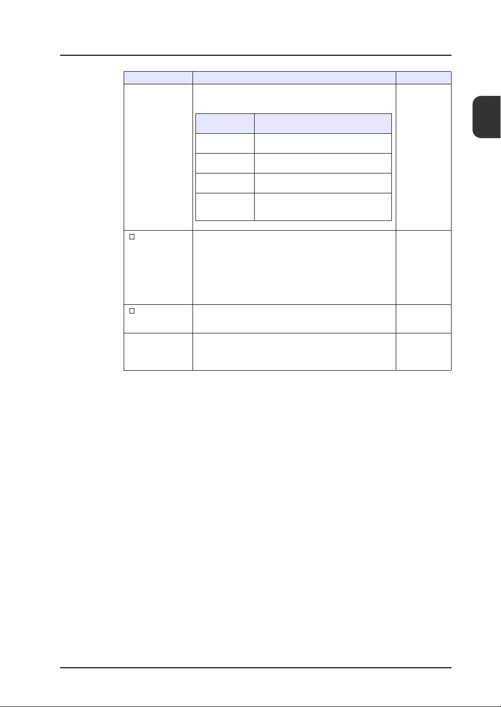
The following manuals relate to the TS Series unit. Reference these manuals as required.
Manual Name Description Reference
TS Series Training Manual (this manual) This manual provides detailed explanations of the
TS Series Connection Manual This manual provides detailed explanations of the
TS Series Hardware Specifications This manual explains the hardware specifications and
V8 Series Reference Manual This manual explains the functions and operating
V8 Series Reference: Additional
Functions
V Series Macro Reference This reference provides an overview of the macros
V8 Series Operation Manual This manual provides detailed explanations of
screen creation process with examples using V-SFT
version 5.
connections between the TS Series unit and each type
of controller as well as communication settings.
operating methods of the TS Series unit.
methods of the V8 Series.
This manual explains the V8 Series functions and
operating methods added to V-SFT version 5.1.0.0 and
later.
available in V-SFT version 5 as well as detailed
explanations of macro editor operations and macro
commands.
information related to operating V-SFT version 5, such
as software composition, editing procedures, and
limitations.
1203NE
2203NE
2022NE
1055NE
1060NE
1056NE
1058NE
No.
For more information on each type of controller (PLC, temperature control, etc.), refer to the manufacturer’s
instruction manual for the corresponding controller.
Notes:
1. No part of this manual may be reproduced without prior permission.
2. The contents of this manual may change without prior notice.
3. Windows and Excel are registered trademarks of Microsoft Corporation in the United States and other
countries.
4. All other company names or product names are trademarks or registered trademarks of their
respective holders.
5. While the utmost care has been taken in the production of this manual, please contact your local
distributor regarding any doubts on the accuracy of explanations.
Page 4
Notes on Safety
In this manual, you will find various notes categorized under the following levels with the signal words “DANGER,”
and “CAUTION.”
DANGER
CAUTION
Note that there is a possibility that items listed with may have serious ramifications.
Indicates an imminently hazardous situation which, if not avoided, will result in death or
serious injury.
Indicates a potentially hazardous situation which, if not avoided, may result in minor or
moderate injury and could cause property damage.
CAUTION
DANGER
• Never use the input and output signals of the TS Series unit for operations that may threaten human life,
cause damage to the system, or as emergency switches. Please design the system so that it can withstand
touch switch malfunctions. Touch switch malfunctions may result in machine accidents or damage.
• Turn off the power supply when you set up the unit, connect new cables, or perform maintenance or
inspections. Failure to do so could cause electric shock or damage to the unit.
• Never touch any terminals while the power is on. Otherwise, electric shock may occur.
• The liquid crystal in the LCD panel is a hazardous substance. If the LCD panel is damaged, avoid ingesting
any leaking liquid crystal. If any liquid crystal spills onto your skin or clothing, use soap to wash it off
thoroughly.
• Never disassemble, recharge, deform by pressure, short-circuit, or reverse the polarity of lithium batteries,
and never dispose of lithium batteries in fire. Failure to follow these conditions may lead to explosion or
ignition.
• Never use lithium batteries that are deformed, leaking, or exhibit any other abnormalities. Failure to follow
these conditions may lead to explosion or ignition.
Page 5

CAUTION
• Check the appearance of the TS Series unit after unpacking. Do not use the unit if any damage or
deformation is found. Using the unit in such a state may lead to fire, damage, or malfunction.
• Please consult your local distributor before using this product in facilities or systems related to nuclear
energy, aerospace, medical, traffic equipment, or mobile installations.
• Operate (and store) the TS Series unit under the environmental conditions indicated in the general
specifications of this manual and related manuals. Failure to do so could cause fire, malfunction, physical
damage or deterioration.
• Understand the following environmental limits for use and storage of TS Series units. Failure to follow these
conditions may result in fire or damage to the unit.
- Avoid locations where there is a possibility that water, corrosive gas, flammable gas, solvents, grinding
fluids, or cutting oil may come into contact with the unit.
- Avoid high temperature, high humidity, and outside weather conditions, such as wind, rain, or direct
sunlight.
- Avoid locations where excessive dust, salt, or metallic particles are present.
- Avoid installing the unit in a location where vibrations or physical shocks may be transmitted.
• Equipment must be correctly mounted so that the main terminal of the TS Series unit cannot be touched
inadvertently. Failure to do so may result in electric shock or accidents.
• Periodically check that the terminal screws on the power supply terminal block and mounting nuts are firmly
tightened. Using the unit with loose screws may result in fire or malfunction.
• Tighten the terminal screws on the TS Series power supply terminal block to an equal torque of 0.5 to
0.6 N•m (5 to 6 kgf•cm). Failure to tighten these screws properly may result in fire, malfunction, or damage
to the system.
• Tighten the mounting nuts on the TS Series unit to equal torque within the specified range. Note that
excessive tightening may distort the panel surface. Failure to tighten these nuts properly may cause the TS
Series unit to fall, malfunction, or short-circuit.
• The TS Series features a glass screen. Do not drop or impart physical shocks to the unit. Such handling will
damage the unit.
• Connect the cables correctly to the terminals of the TS Series unit in accordance with the specified voltage
and wattage. Failure to supply the correct voltage or wattage, or improper cable connection may cause fire,
malfunction, or damage to the unit.
• Always ground the TS Series unit. Ground the FG terminal of the TS Series unit with an independent D
class grounding (ground resistance of 100 Ω or less). Failure to do so may result in electric shock or fire.
• Prevent any conductive particles from entering into the TS Series unit. Failure to do so may lead to fire,
damage, or malfunction.
• Do not attempt to repair the TS Series unit at your site. Contact Hakko Electronics Co., Ltd. or the
designated contractor for repairs.
• Do not attempt to repair, disassemble, or modify the TS Series unit. Hakko Electronics Co., Ltd. is not
responsible for any damages resulting from repairs, disassembly, or modification of TS Series units
performed by unauthorized personnel.
• Do not use sharp-pointed tools to press touch switches. Doing so may damage the screen.
• Only personnel who possess the required knowledge and technical skills are authorized to set up the unit,
connect the cables, and perform maintenance and inspections.
• Lithium batteries contain combustible material such as lithium and organic solvents. Mishandling may cause
heat, explosion, or ignition resulting in fire or injury. Read the related manuals carefully and handle lithium
batteries correctly as instructed.
• Do not press two or more positions on the screen at the same time. If two or more positions are pressed at
the same time, the switch located between the pressed positions will be activated.
• Take sufficient safety precautions during operations such as changing settings during running, forced output,
start, and stop. Operating errors may cause unexpected machine motions, resulting in machine accidents or
damage.
• In facilities where TS Series unit failure could lead to accidents that threaten human life or result in other
serious damage, make sure that such facilities are equipped with adequate safeguards.
• TS Series units must be disposed of as industrial waste.
• Before touching the TS Series unit, discharge any static electricity from your body by touching grounded
metal. Excessive static electricity may cause malfunction or damage to the unit.
Page 6

[General Notes]
• Never bundle control cables and communication cables with high-voltage and large-current carrying cables
such as power supply cables. Keep these cables at least 200 mm away from high-voltage and large-current
carrying cables. Otherwise, malfunction may occur due to noise.
• When using the TS Series unit in an environment where a source of high-frequency noise is present, it is
recommended that the FG shielded cable (communication cable) be grounded at both ends. However, the
cable may be grounded only at one end if necessary due to unstable communication conditions or for other
reasons.
• Plug connectors and sockets of the TS Series unit in the correct orientation. Otherwise, malfunction or
damage may occur.
• Do not use thinners for cleaning because it may discolor the surface of the TS Series unit. Use a commercially
available alcohol-based cleaner instead.
• If a “data receive error” occurs when the TS Series unit and the counterpart unit (PLC, temperature controller,
etc.) are started at the same time, read the instruction manual for the counterpart unit and handle the error
accordingly.
• Avoid discharging static electricity on the mounting panel of the TS Series unit. Static charge can cause
malfunctions due to noise.
• Avoid prolonged display of any fixed pattern. An afterimage may remain due to the characteristics of the liquid
crystal display. If a prolonged display of a fixed pattern is expected, use the backlight’s auto OFF function.
[Notes on the LCD Screen]
Note that the following conditions may occur under normal circumstances.
• The response time, brightness, and colors of the TS Series unit may be affected by the ambient temperature.
• Tiny spots (dark or luminescent) may appear on the display due to liquid crystal characteristics.
• Each unit varies slightly with respect to brightness and colors.
Page 7

Contents
Preface
Notes on Safety
1. Creating New Files .......................................................................................................... 1-1
2. Creating Switches and Lamps......................................................................................... 2-1
3. Creating Overlaps ........................................................................................................... 3-1
4. Entry Screens.................................................................................................................. 4-1
5. Alarm Screens.................................................................................................................5-1
6. Trend Screen (Trend Sampling)...................................................................................... 6-1
7. Screen Data Transfer ...................................................................................................... 7-1
Page 8
1. Creating New Files
1. Creating New Files
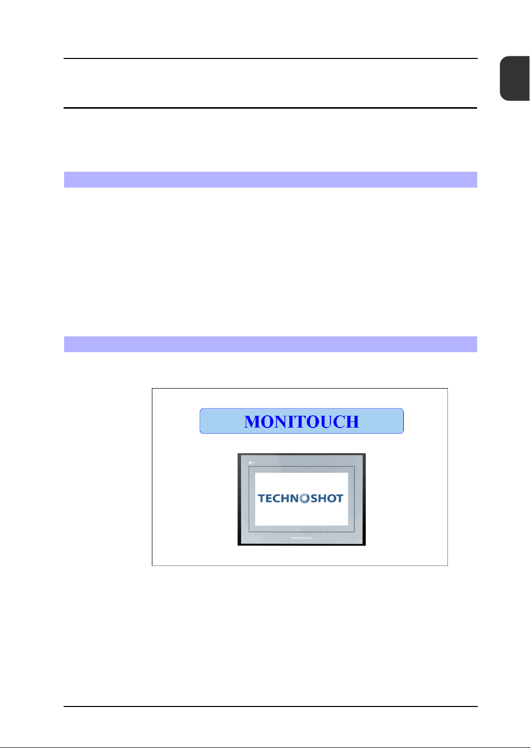
This chapter explains how to create new files and the initial screen displayed when the unit first
starts up after turning on the power.
Contents
Screen Example.................................................................................................................. page 1-1
Screen Creation .................................................................................................................. page 1-2
1. Creating a New File .................................................................................................. page 1-2
2. Changing the Background Color .............................................................................. page 1-5
3. Drawing Graphics ..................................................................................................... page 1-7
4. Moving and Aligning Parts...................................................................................... page 1-13
5. Saving Files ............................................................................................................ page 1-16
Unit Operation................................................................................................................... page 1-17
Error Display............................................................................................................... page 1-17
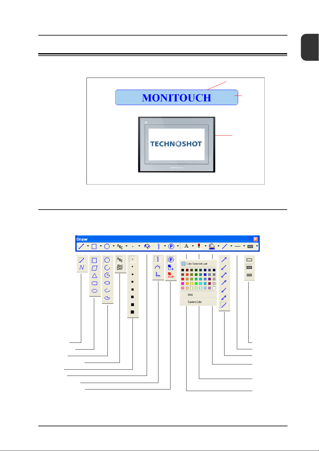
Screen Example
The drawing tools are used to draw graphics, place text, and paste image files (JPEG, bitmap).
1
Contents
1-1
Page 9
1. Creating New Files
1. Creating a New File
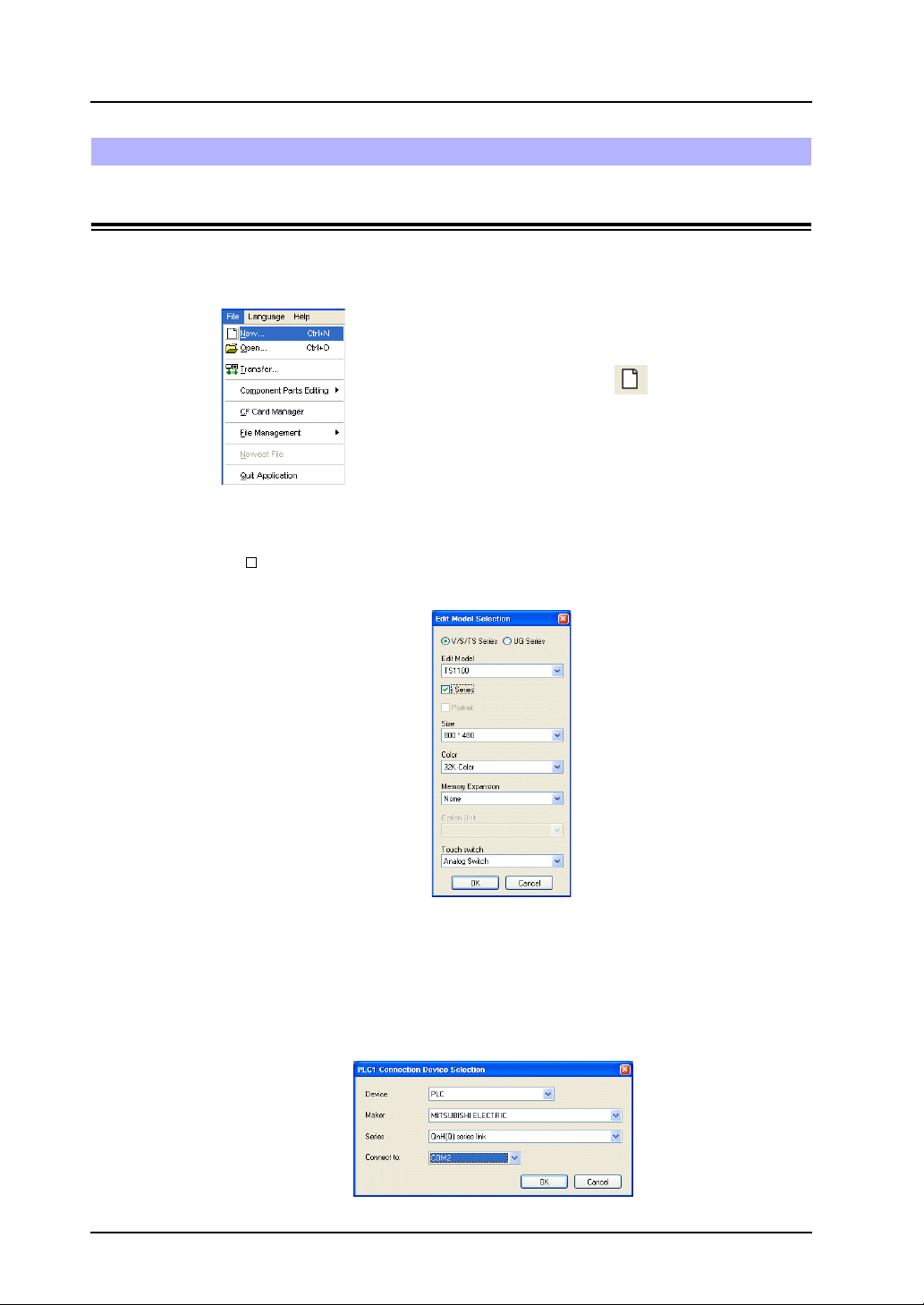
1. Start V-SFT-5.
2. Click [File] → [New] or click the [New File] icon.
3. Configure the following settings in the [Edit Model Selection] dialog box and click [OK].
Create the example screen in this manual with the following settings.
Edit Model : TS1100
i Series : Selected
Color : 32K-Color
Screen Creation
New file icon
or
1-2
4. Configure the PLC type and TS connection port in the [PLC1 Connection Device Selection]
dialog box and click [OK].
Create the example screen in this manual with the following settings.
Device connected : PLC
Maker : MITSUBISHI ELECTRIC
Series : QnH (Q) series link
Connect to : COM2
Page 10
1. Creating New Files
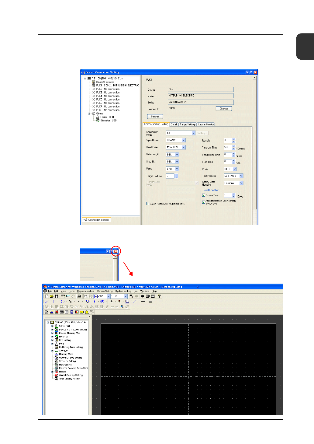
5. Configure the communication parameters in the [Device Connection Setting] window. For
more information on settings in the [Device Connection Setting] window, refer to the “TS
Series Connection Manual.”
1
Screen Creation
6. Click the [Close] button to close the [Device Connection Setting] window.
The [Screen [0] Edit] window is displayed.
Close
1-3
Page 11
1. Creating New Files
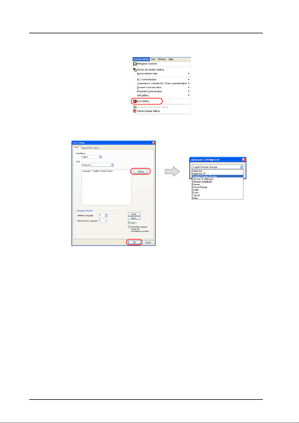
7. Click [System Setting] → [Font Setting]. The [Font Setting] dialog box is displayed.
8. Set the font using the [Setting] button. Click the [OK] button to close the dialog box.
For more information on settings in the [Font Setting] dialog box, refer to the “V8 Series
Reference Manual.”
1-4
Page 12
1. Creating New Files
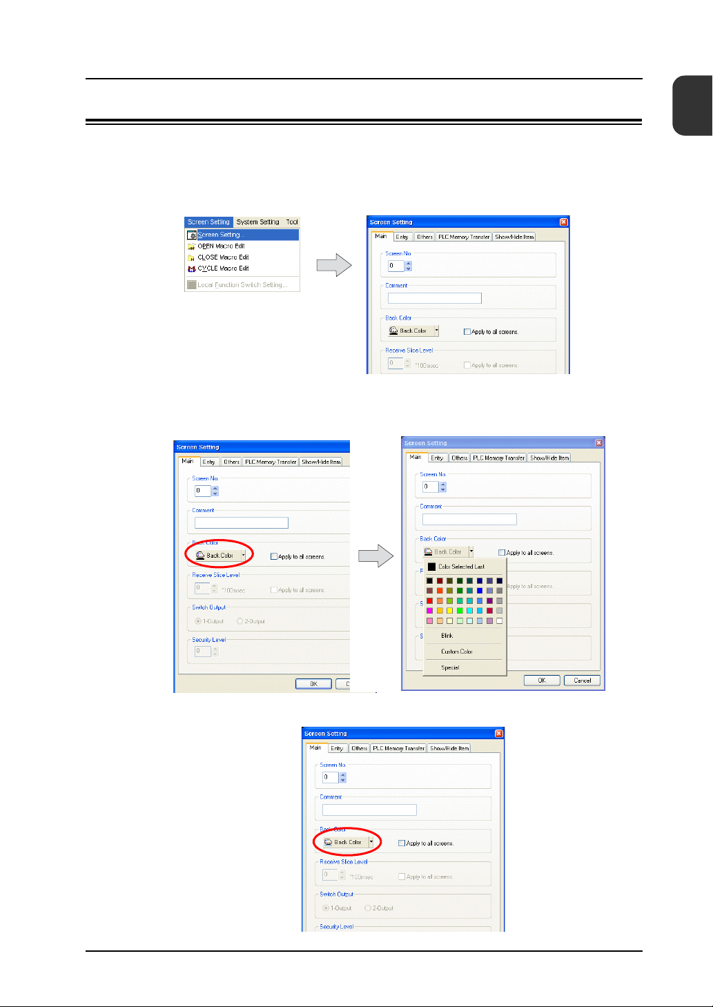
2. Changing the Background Color
This section explains how to change the background color.
1. Click [Screen Setting] → [Screen Setting].
The [Screen Setting] dialog box is displayed.
2. Click the [Back Color] button on the [Main] tab. A drop-down list for color selection is
displayed.
Select the desired background color.
1
Screen Creation
3. The selected color is displayed on the icon and the background changes to this color.
1-5
Page 13
1. Creating New Files
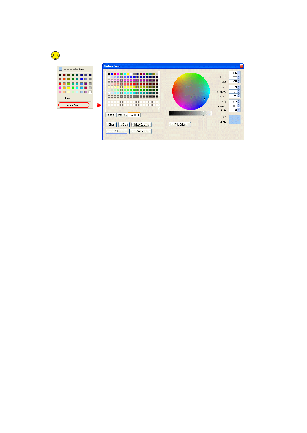
Click [Custom Color] to select a color that is not shown on the drop-down list. The [Custom Color]
dialog box is displayed.
Select the desired background color.
1-6
Page 14
1. Creating New Files
3. Drawing Graphics
This section explains how to use the drawing tools to create text and draw graphics.
3.1 Draw Toolbar
The icons on the [Draw] toolbar are shown below. Click the → symbol on the right of each icon to
change the properties of each icon’s function.
1
Screen Creation
Te xt
Rectangle
Bitmap image
Straight
Line
Rectangle
Circle
Text/Multi Text
Dot
Paint
Graph Scale
Pattern/Library
Frame Type
Line Type
Arrow Type
Paint Color/
Background
Line
Color/Frame
Color
Character Color
1-7
Page 15
1. Creating New Files
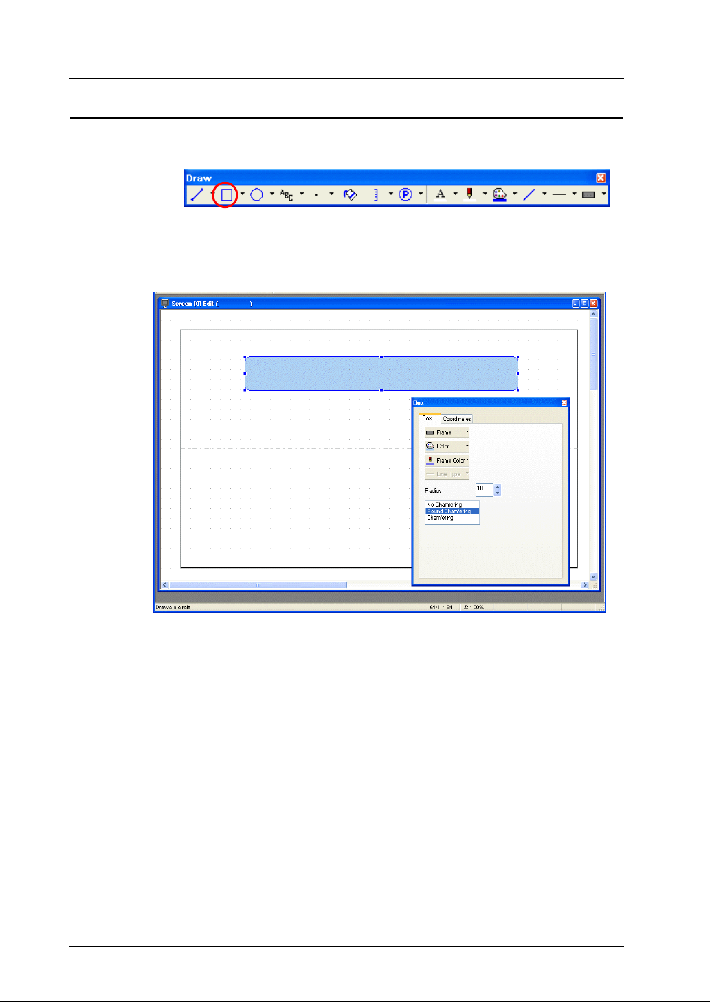
3.2 Creating a Rectangle
1. Click the [Rectangle] icon on the [Draw] toolbar. The [Rectangle] icon becomes depressed
and the mouse cursor changes to a cross-shaped cursor.
2. Drag from the start point to the end point on screen using the mouse. This draws a rectangle.
3. Set the color and frame type in the item dialog box.
1-8
Page 16
1. Creating New Files
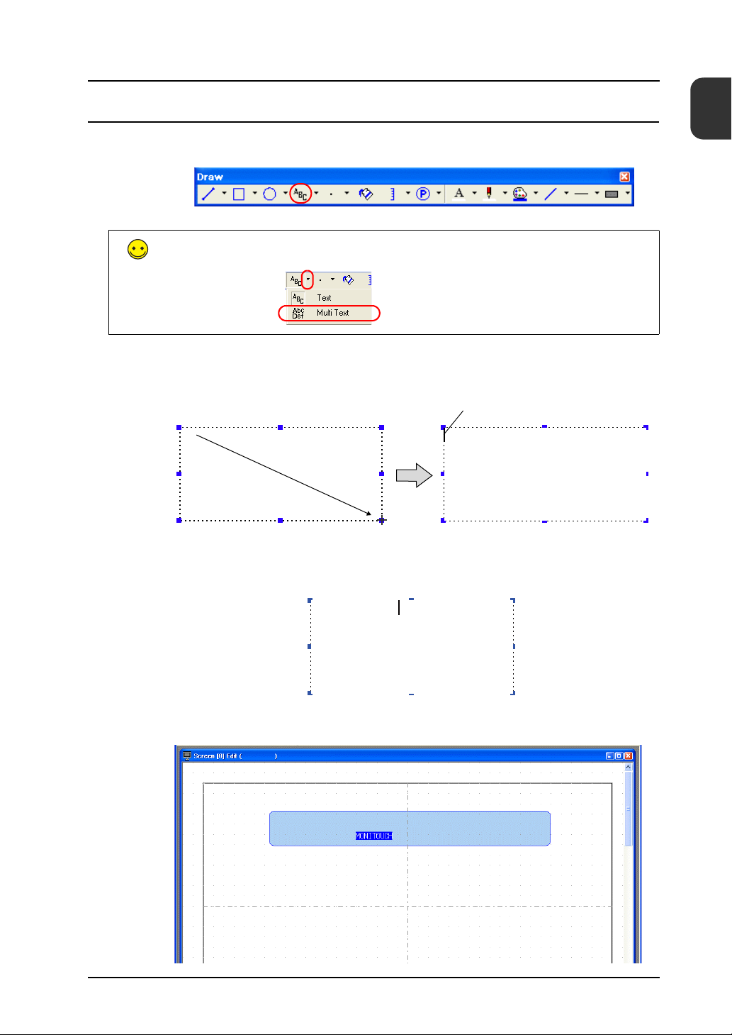
3.3 Creating Text
1. Click the [Text] icon on the [Draw] toolbar.
The [Text] icon becomes depressed.
Use [Multi Text] to enter more than two lines of text.
2. Drag from the start point to the end point on screen using the mouse.
The specified area and a blinking cursor are displayed on screen.
1
Screen Creation
Blinking cursor
Drag
3. Enter text.
MONITOUCH
4. Click a location on the screen other than the text.
1-9
Page 17
1. Creating New Files
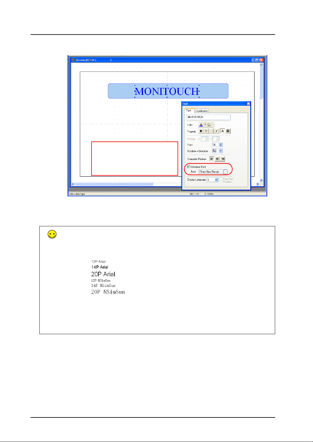
5. Click the text to display its item dialog box. Change the text color and text size properties.
Windows fonts on the computer can
also be set in addition to the standard
bitmap fonts.
Windows fonts on the computer can
also be set.
Windows Fonts
The use of Windows fonts enables text size settings from 6 to 999 points and results in
smoother display.
However, note that a common font should be used when editing on multiple computers
because the types of Windows fonts can vary between computers.
A warning message is displayed if attempting to use a Windows font that is not present on
the computer. In this case, editing cannot be performed unless the missing font is
substituted with another Windows font or the missing font is installed.
1-10
Page 18
1. Creating New Files
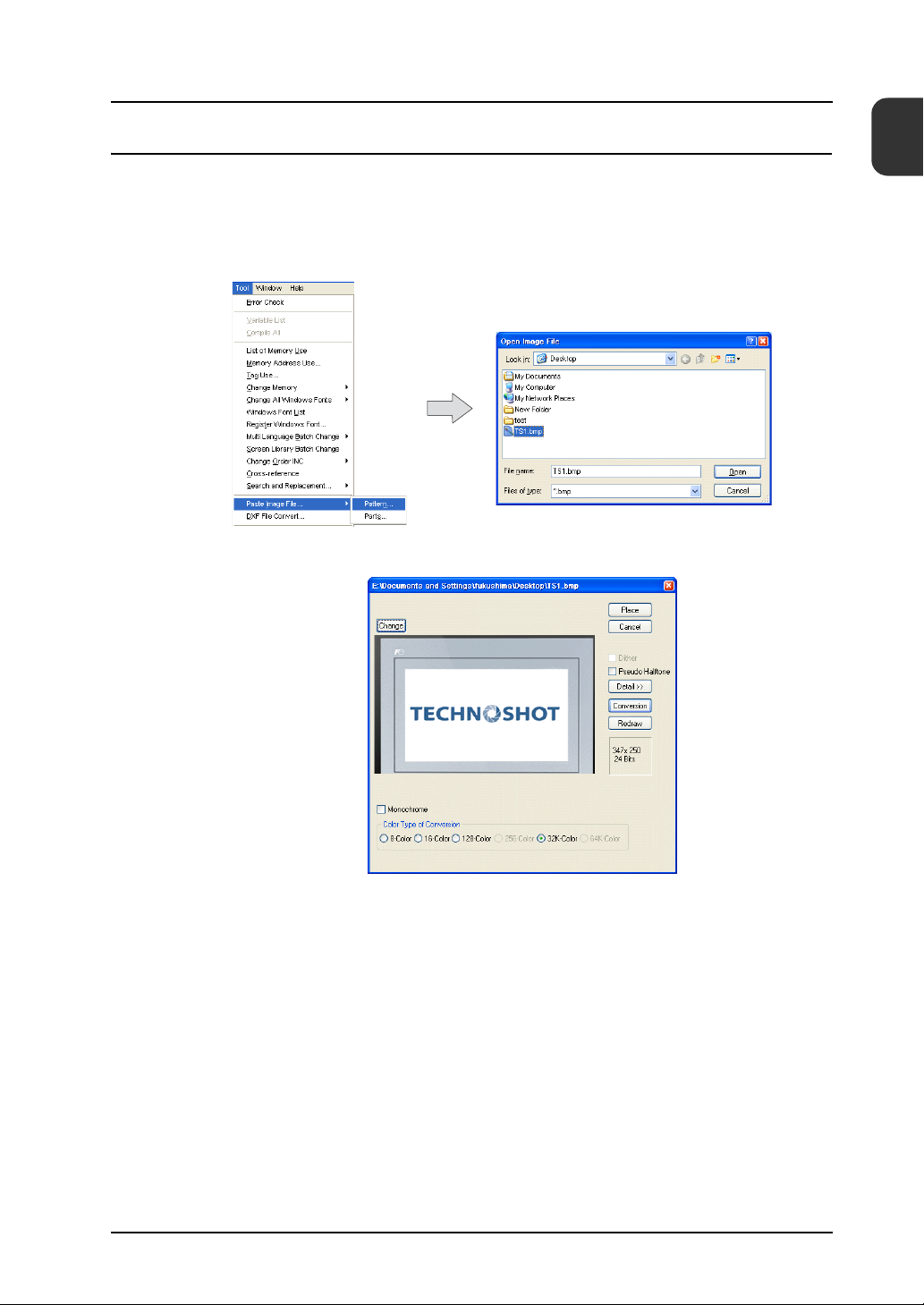
3.4 Pasting JPEG/Bitmap Files
This section explains how to load JPEG or bitmap files of company logos or machine image data
onto the screen as pattern data.
1. Click [Tool] → [Paste Image File] → [Pattern].
The [Open Image File] dialog box is displayed.
2. Select the file to load and click [Open]. The loaded image is displayed.
1
Screen Creation
1-11
Page 19
1. Creating New Files
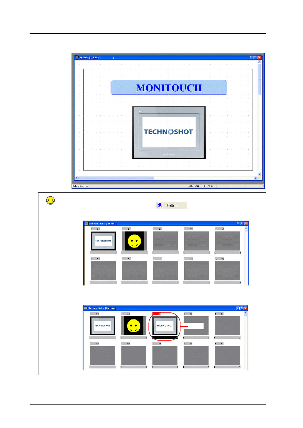
3. Click the [Place] button to place the image on the screen.
The loaded image is registered to [Registration Item] → [Pattern]. The image can be used on
other screens by clicking the [Pattern] icon ( ) on the [Draw] toolbar and selecting
the image for placement.
Loading the same image multiple times results in multiple registrations and increases the screen
data size. Delete any unnecessary patterns.
Delete
1-12
Page 20
1. Creating New Files
4. Moving and Aligning Parts
This section explains how to move parts, change item size, and align multiple parts.
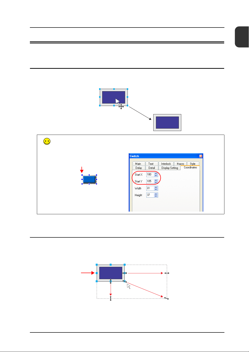
4.1 Moving Parts
1. Click on the part. Handles are displayed around the part.
2. With the mouse cursor displaying a cross-shaped mark, drag the part to another position.
The part position can also be set using [Start X] and [Start Y] on the [Coordinates] tab in the item
dialog box.
Start point
1
Screen Creation
Move
4.2 Enlarging and Reducing Part Size
1. Click on the part. Handles are displayed around the part.
2. Place the mouse cursor over a handle. The mouse cursor changes to a ↔ mark.
3. Drag the handle with the mouse cursor displayed as ↔.
Handle
Mouse cursor changes to
↔ when nearing a handle
Enlarge vertically
Enlarge horizontally
Enlarge horizontally and vertically
1-13
Page 21
1. Creating New Files
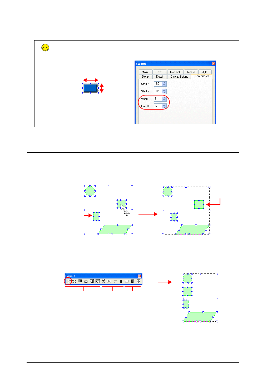
The part size can also be set using [Width] and [Height] on the [Coordinates] tab in the item
dialog box.
Width
Height
4.3 Aligning Parts and Matching Size
This section explains how to align the positions and match the sizes of multiple parts at once.
1. Select the parts for alignment. Handles are displayed around the parts.
2. Hold down the [Ctrl] key and click the reference part. The handle color of this part changes
and the part is specified as the reference part.
Reference partClick
Reference part
3. Use the [Layout] icons or the [Edit] menu → [Arrangement (Equal)] submenu or [Put All in
Same Size] submenu to align the positions or match the sizes of parts.
Example: Left justification
Align parts to the left of
Placement Arrange/
equalize
Match
size
the reference part.
1-14
Page 22
1. Creating New Files
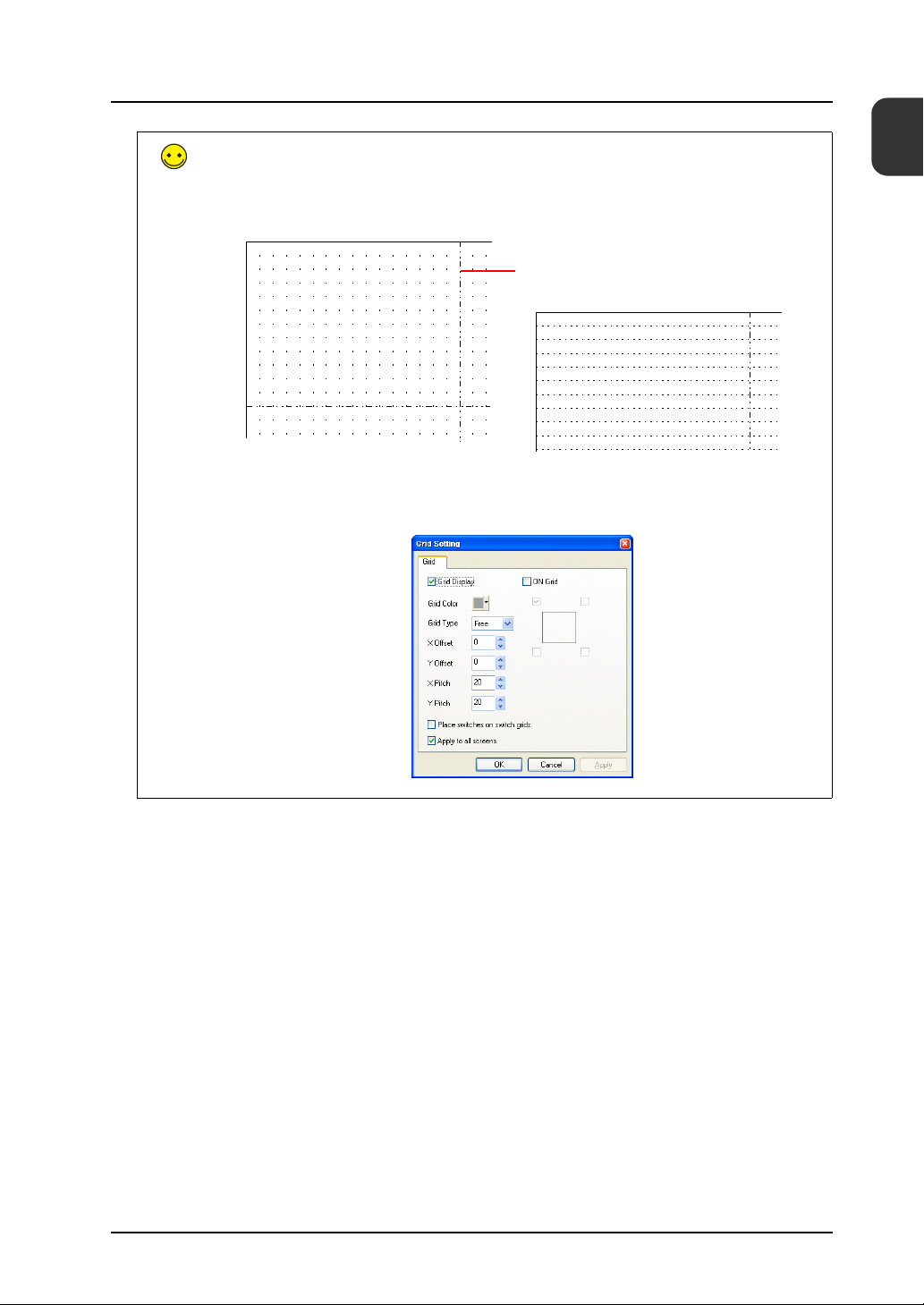
Grid Settings/Center Line Display
Use [Center Line Display] and [Grid Display] to display center lines and grid lines of reference on
screen to assist with item placement. These lines are only displayed in the V-SFT software and
not on the unit.
Center line
Display the center lines by clicking [View] → [Customize] → [Center Line Display].
Display grid line settings by clicking [View] → [Grid] → [Grid Display] and configure grid lines by
clicking [View] → [Grid] → [Grid Setting].
1
Screen Creation
1-15
Page 23
1. Creating New Files
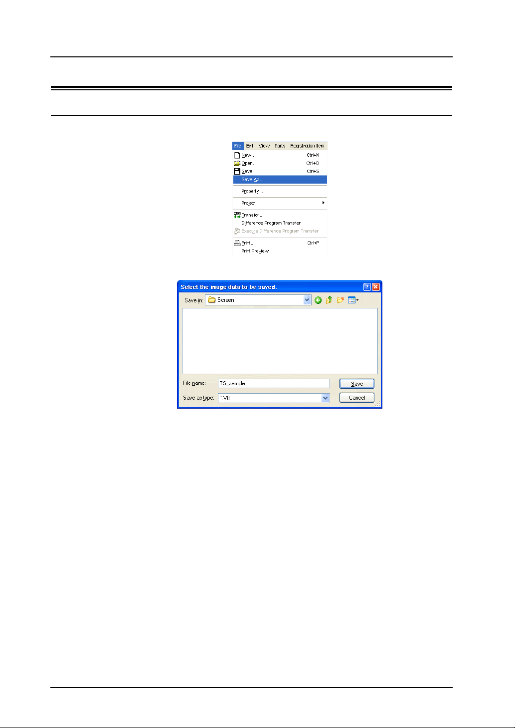
5. Saving Files
5.1 Saving as a New File
1. Click [File] → [Save As]. The [Select the image data to be saved.] dialog box is displayed.
2. Enter the desired filename and click [Save].
1-16
File creation is complete. Screen data may now be transferred to the unit.
Page 24
1. Creating New Files
Unit Operation
Screen data is displayed when the TS Series unit and PLC are connected correctly. Check that
the unit operates properly.
MONITOUCH
TECHNOSHOT
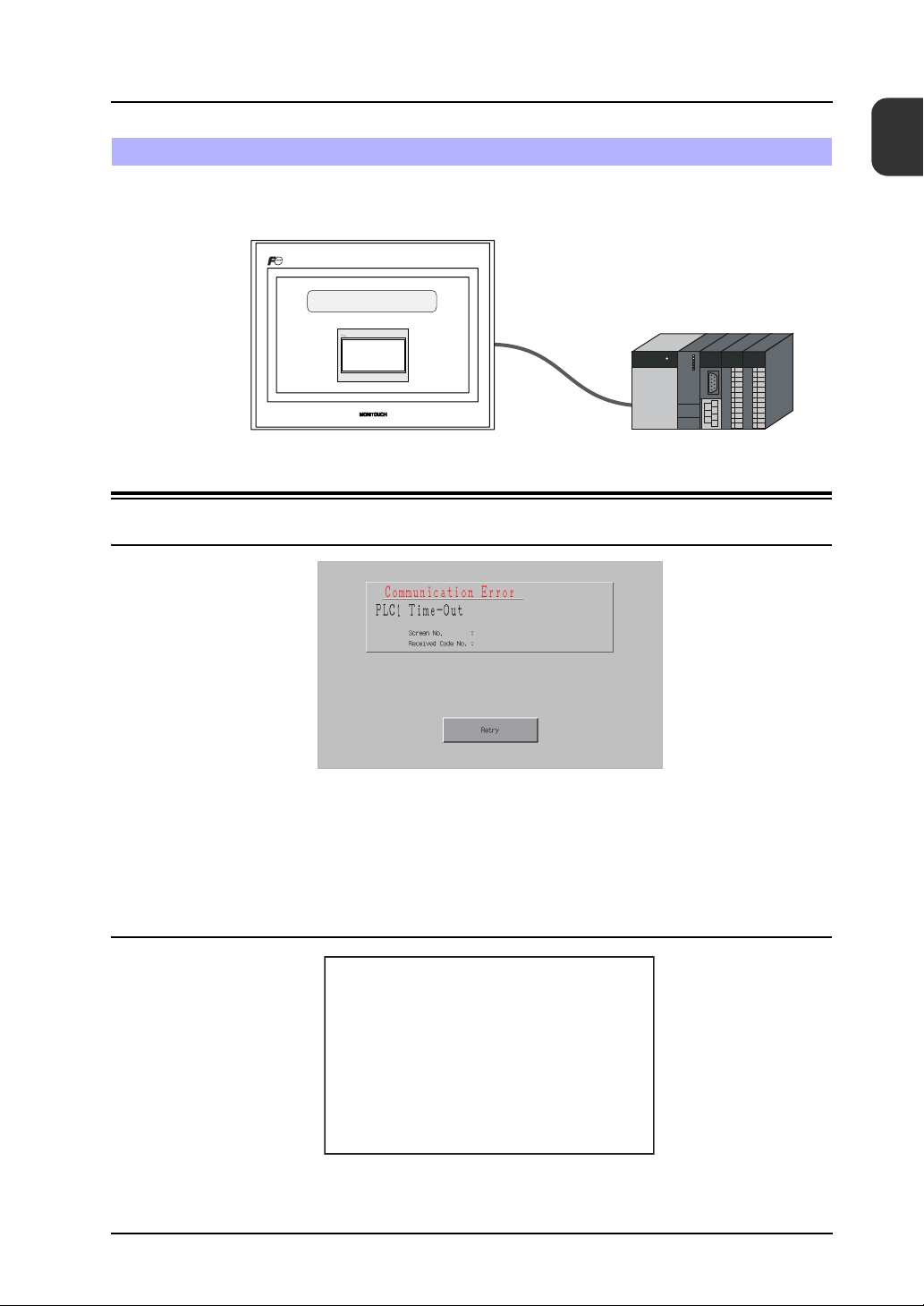
1. Error Display
1.1 Communication Error - Timeout
1
Unit Operation
Communication is not being performed correctly due to any of the following reasons.
• The model select for screen data in the [Device Connection Setting] window differs from the
actual connected model.
• The communication parameters of the TS Series unit and the PLC do not match.
• The communication cable is not connected correctly or disconnected.
1.2 Screen No. Error
Check the value of the screen number command specified in the read area (n + 2).
Data Loading...
Screen No. Error
1-17
Page 25
1. Creating New Files
The TS Series unit displays screens by looking at the memory value of the screen number
command when communication starts. The “Screen No. Error” message is displayed if this value
is set to a screen number that does not exist.
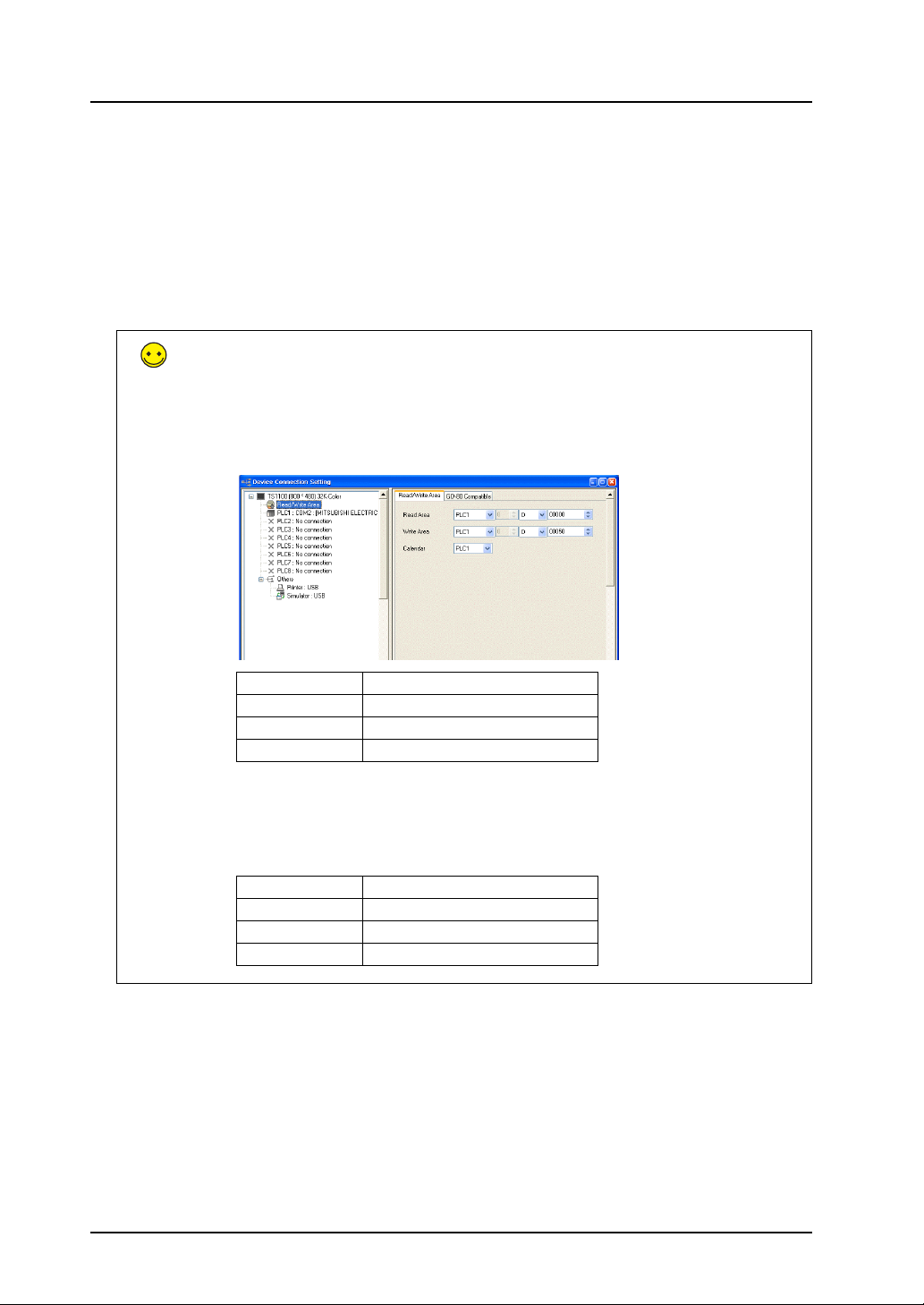
For the screen data in this manual, the [Read Area] value is “D0000” so the screen number
command memory is “D0002”. For data where screen numbers 0 to 5 have been created:
Read Area
The [Read Area] and [Write Area] settings can be accessed by clicking [System Setting] →
[Device Connection Setting].
The read area is the memory address where the PLC issues display or operation commands to
the TS Series unit. Three words of consecutive memory addresses are secured for this
purpose.
D0002 = 0 to 5 → Display correctly
D0002 = 6 to 9999 → Screen No. Error
Read Area Description Setting Example
n Subcommand D0
n + 1 Screen status command D1
n + 2 Screen number command D2
Write Area
This memory address is for outputting the screen status from the TS Series unit to the PLC.
Three words of consecutive memory addresses are secured for this purpose.
Write Area Description Setting Example
n Subcommand state D50
n + 1 Screen status D51
n + 2 Displayed screen number D52
1-18
Page 26
2. Creating Switches and Lamps
2. Creating Switches and Lamps
This chapter explains how to create screens that contain switches and lamps.
Contents
Screen Example.................................................................................................................. page 2-1
Screen Creation .................................................................................................................. page 2-2
1. Editing Screens ...................................................................................................... page 2-13
2. Procedure for Changing Parts ................................................................................ page 2-13
Confirming Unit Operation ................................................................................................ page 2-19
1. Memory Addresses................................................................................................. page 2-19
2. Unit Operation ........................................................................................................ page 2-19
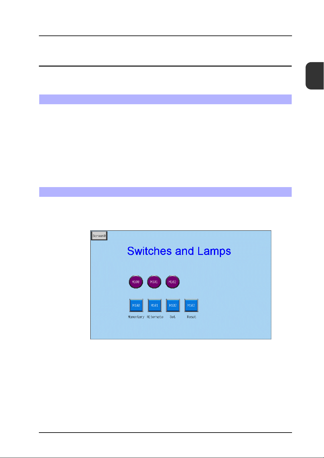
Screen Example
Create the following example screen that uses switch output to turn lamps on and off and switches
to another screen using a switch.
2
Contents
2-1
Page 27
2. Creating Switches and Lamps
1. Editing Screens
1.1 Creating a New Screen
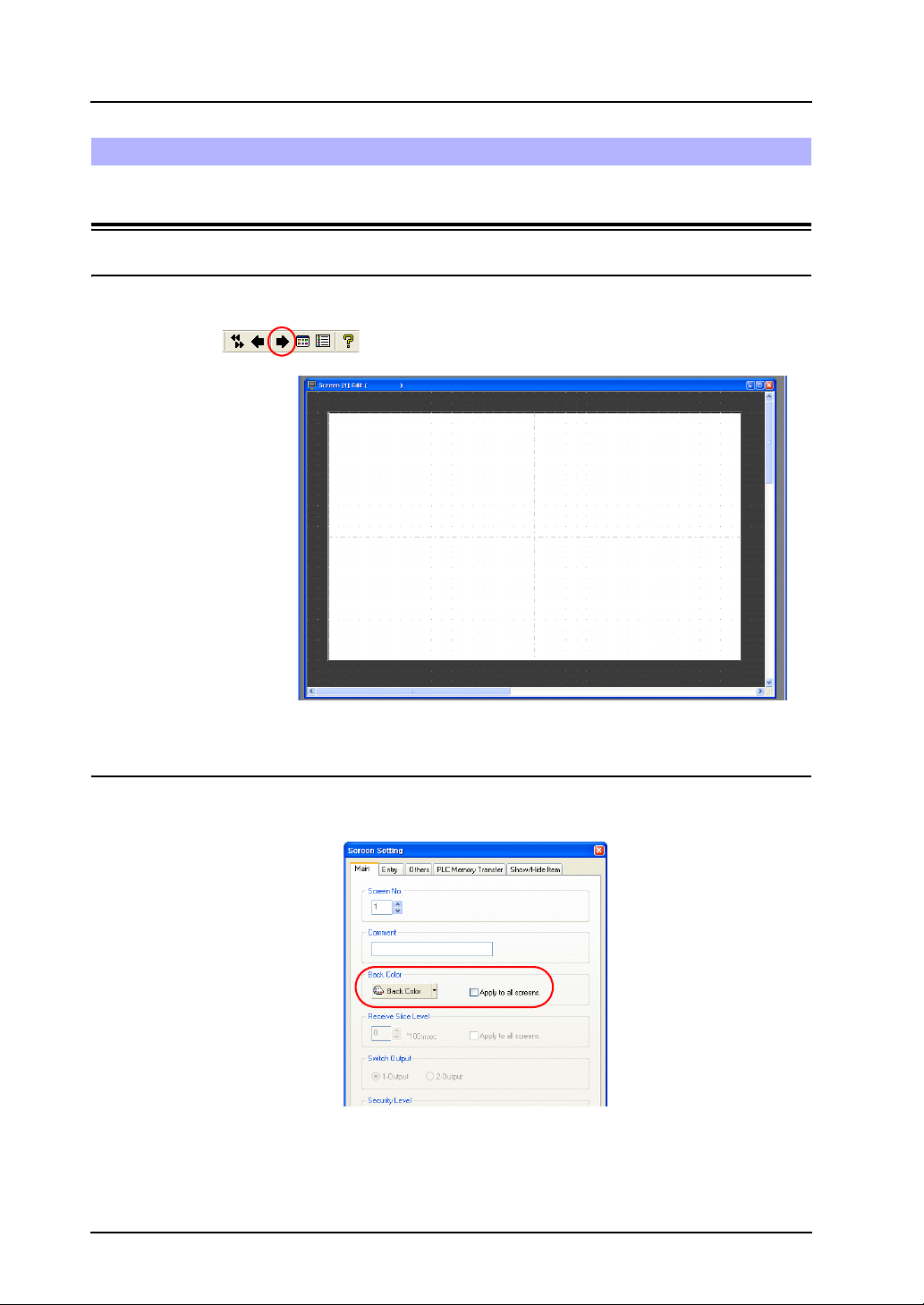
3. Click the [Next Screen] icon to display the [Screen [1] Edit] window.
Screen Creation
1.2 Changing the Background Color
Change the background color of the screen by clicking [Screen Setting] → [Screen Setting].
For more information, refer to “Changing the Background Color” on page 1-5.
2-2
Page 28
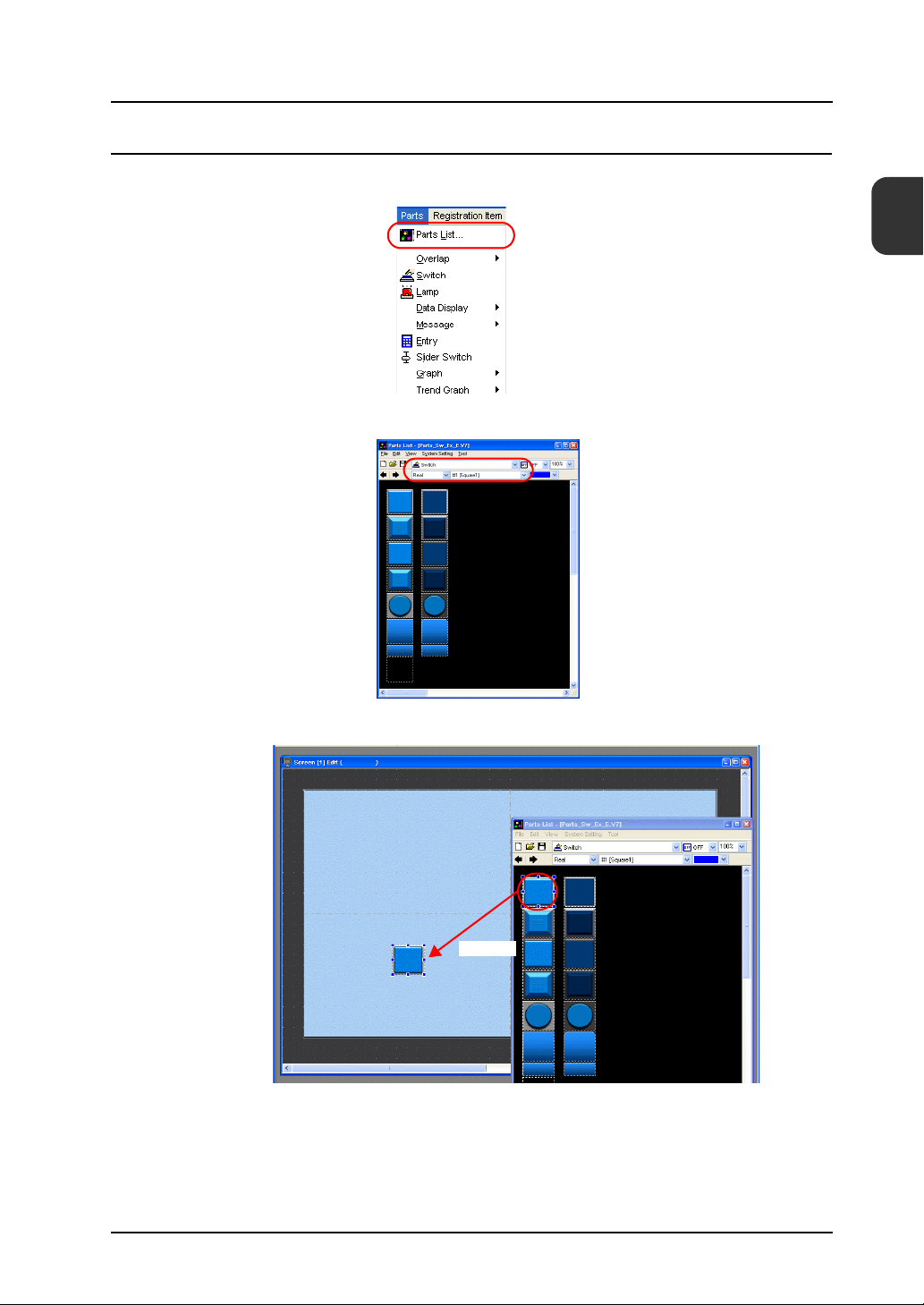
1.3 Placing Switches
1. Click [Parts] → [Parts List]. The [Parts List] window is displayed.
2. Select [Switch], [Real], and [#1 [Square1]].
2. Creating Switches and Lamps
2
Screen Creation
3. Select a switch and drag it onto the screen. This places the switch on the screen.
Drag
2-3
Page 29
2. Creating Switches and Lamps
In addition to the [Parts List], the following four methods are available for placing parts.
1. Placement from the parts icons
2. Placement from the [Parts] menu
3. Placement from the [Catalog] dialog box
4. Placement using the wizard
1. Parts icons
2. [Parts] menu
3. [Catalog] dialog box
4. Wizard ([Parts] menu)
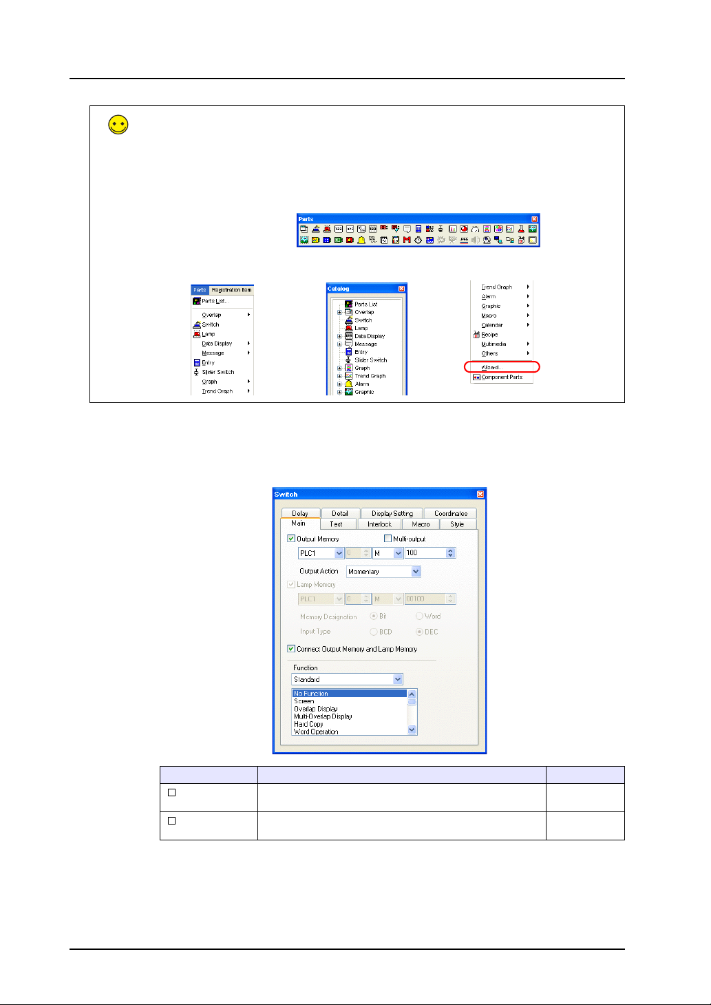
5. Configure each setting in the switch’s item dialog box.
•[Main] tab
Set the bit memory address for output and select a setting for [Function].
2-4
Item Details Setting Value
Output Memory
Multi-output
Set the bit memory address to output when the switch is pressed. Selected
Select this checkbox to perform a single output action with
respect to multiple memory addresses.
M100
Deselected
Page 30
2. Creating Switches and Lamps
Item Details Setting Value
Output Action Set the write operation to perform with respect to the output
memory address.
Momentary
Switch
Operation
Set The specified bit memory address is set to
Reset The specified bit memory address is reset
Momentary
Momentary W
Alternate The specified bit memory address is
Lamp Memory
Connect Output
Memory and Lamp
Memory
Function Set the function of the switch, or in order words, how the switch
*1 For more information on functions, refer to the “V8 Series Reference Manual.”
Change the display of the switch area.
Deselected:
Pressing the switch turns on the lamp in the switch. Releasing
your finger from the switch turns the lamp off.
Selected:
Set the memory address for the lamp display using [Memory
Designation] and [Input Type].
Select this checkbox to use the same memory address for output
memory and lamp memory.
should work when it is pressed. Functions that are frequently
used include “Screen”, “Overlap Display”, and “Multi-Overlap
*1
Display”.
“ON”.
to “OFF”.
The specified bit memory address is set to
“ON” while the switch is depressed.
alternately set (ON) and reset (OFF) each
time the switch is pressed.
Output Processing
2
Screen Creation
-
Selected
No Function
2-5
Page 31

2. Creating Switches and Lamps
•Text
Set the text displayed on the switch.
If the switch displays
different text in the ON and
OFF states, register the
text to display in each state
on the [ON] and [OFF]
tabs.
Item Details Setting Value
OFF, ON to P128
Pattern No.
Color
Property
Enlarge
Point
Rotation + Direction
Windows Font
Register the text to be displayed on the switch. M100
Set the text color, properties, and text size. -
• Changes to the settings on the [Interlock], [Macro], [Style], [Delay], [Detail], and [Display
Setting] tabs are not covered in this section.
2-6
Page 32

1.4 Creating Multiple Copies of Switches
This section explains how to copy a switch multiple times.
1. Select a switch. Handles are displayed around the switch.
2. Click [Edit] → [Multi Copy] or click the [Multi-copy] icon. The [Multi Copy] dialog box is
displayed.
2. Creating Switches and Lamps
2
Screen Creation
or
3. Set the options as shown below and click [OK]. This copies the switch multiple times.
2-7
Page 33

2. Creating Switches and Lamps
4. Click [View] → [Customize] → [Memory Display]. Memory addresses are displayed at the
lower left on each switch.
5. Change the switch text and output action to the following.
[Main] tab
Output Action: Alternate
[Text] tab
OFF: M101
This completes the switch creation process.
[Main] tab
Output Action: Set
[Text] tab
OFF: M102
[Main] tab
Output Memory:
M102
Output Action: Reset
[Text] tab
OFF: M102
2-8
Page 34

1.5 Placing Lamps
1. Click [Parts] → [Parts List]. The [Parts List] window is displayed.
2. Select [Lamp], [Real], and [#0 [Circle1]].
3. Select a lamp and drag it onto the screen. This places the lamp on the screen.
2. Creating Switches and Lamps
2
Screen Creation
Drag
4. Configure each setting in the lamp’s item dialog box.
•[Main] tab
Set the memory address for the lamp.
Item Details Setting Value
Lamp Memory The display of the lamp area can be changed.
Function Set the lamp’s function.
Set the memory address for the lamp display using [Memory
Designation] and [Input Type].
Normally select [No Function].
M100
No Function
2-9
Page 35

2. Creating Switches and Lamps
• [Text] tab
Set the text displayed on the lamp.
If the lamp displays different text in
the ON and OFF states, register the
text to display in each state on the
[ON] and [OFF] tabs.
Item Details Setting Value
OFF, ON to P128
Pattern No.
Color
Property
Enlarge
Point
Rotation + Direction
Windows Font
Register the text to be displayed on the lamp. M100
Set the text color, properties, and text size. -
• Changes to the settings on the [Style], [Detail], and [Display Setting] tabs are not covered in
this section.
2-10
Page 36

1.6 Creating Multiple Copies of Lamps
Create multiple copies of lamps using the same procedure for multiple copies of switches.
2. Creating Switches and Lamps
1. Select the lamp. Handles are displayed around the lamp.
2. Click [Edit] → [Multi Copy] or click the [Multi-copy] icon. The [Multi Copy] dialog box is
displayed.
or
2
Screen Creation
3. Set the options as shown below and click [OK]. This copies the lamp multiple times.
2-11
Page 37

2. Creating Switches and Lamps
4. Change the text displayed on each lamp.
This completes the lamp creation process.
[Text] tab
M101
[Text] tab
M102
2-12
Page 38

2. Procedure for Changing Parts
Perform the following procedure to change the design or color of parts placed on the screen.
2.1 Changing Parts
2. Creating Switches and Lamps
2
1. Select the part for changing to display its item dialog box.
2. Click [Style] → [Change Part]. The [Change Part] window is displayed.
Screen Creation
2-13
Page 39

2. Creating Switches and Lamps
3. Select the part using [Change Part Color] and [Part Type Change].
Item Details
Maintain Size
Pattern Change The pattern image of OFF, ON, and patterns up to P128 can be checked.
Change Part Color Change the color.
Part Type Change Change the part type.
Deselected:
Change to the default size.
Selected:
Maintain the size prior to changing.
Real/Sign/3D
Circle/Square/Plant/Icon etc.
4. Select the part properties for changing and click [Select] to change the lamp on the screen.
2-14
Page 40

2.2 Changing the Color of Parts
1. Select the part for changing to display its item dialog box.
2. Select the pattern (OFF/ON/P3 or higher) whose color is to be changed on the [Style] tab and
click [Customize].
2. Creating Switches and Lamps
2
Screen Creation
3. Select an image and color in the [Change the image] window.
2-15
Page 41

2. Creating Switches and Lamps
Different color settings for OFF and ON can be configured by changing the color in the [Change
the image] window.
Before change
After change
OFF ON
2-16
Page 42

2.3 Placing Text
This section explains how to place the screen title and other text elements.
♦ Creating Text
1. Click the [Text] icon on the [Draw] toolbar. A cross-shaped cursor is displayed.
2. Creating Switches and Lamps
2
Te xt
Screen Creation
Te xt
2. Click on the screen. A text frame is displayed.
3. Enter text.
4. Click a location on the screen other than the text.
5. Click the text to display its item dialog box. Change the text color and text size properties.
2-17
Page 43

2. Creating Switches and Lamps
2.4 Creating a Switch for Changing to Another Screen
This section explains how to place a switch that changes between screen 0 and screen 1 when
pressed.
1. Place a switch.
2. Set [Function] to “Screen” in the switch’s item dialog box and set [Screen No.] to the number of
the destination screen.
Screen 1
Switch
Function: Screen 0
Screen 0
Switch
Function: Screen 1
3. Adjust the switch color and position.
This completes the screen creation process. The next section covers confirming screen operation
on the TS Series unit.
2-18
Page 44

1. Memory Addresses
The memory addresses used in this example are listed below.
2. Creating Switches and Lamps
Confirming Unit Operation
2
Memory
Address
M100 Switch output memory (momentary), lamp memory
M101 Switch output memory (alternate), lamp memory
M102 Switch output memory (set/reset), lamp memory
2. Unit Operation
This section explains how to confirm screen operation after transferring screen data to the unit.
2.1 Switching Screens
1. Screen 0 is displayed initially.
(Refer to the next page if a different screen or “Screen No. Error” is displayed.)
Memory Contents
Confirming Unit Operation
2. Press [Screen1] at the upper right of the screen. The screen changes to display screen 1.
2-19
Page 45

2. Creating Switches and Lamps
Changing Screens Using PLC Commands (External Commands)
The [Read Area] and [Write Area] settings, accessed by clicking [System Setting] → [Device
Connection Setting], are used for this purpose. “D0002” is used for the screen number
command memory in this manual.
Setting “D0002” to the screen number will allow the display to change. Note that the screen
number of the currently displayed screen is stored using “D0052” in the [Write Area].
PLC
Screen0
D0002
D0052
D0002
D0052
0
0
PLC
Screen1
1
1
2-20
The screen number to display when the unit is powered on is also determined by “D0002”.
The “Screen No. Error” message is displayed if a screen number that does not exist is set.
For more information on the [Read Area] and [Write Area], refer to page 1-17.
Page 46

2.2 Switch Output and Lamp Display
♦ Momentary Switch
The output memory address is set to “ON” while the switch is depressed.
1. Press the M100 (momentary) switch. The M100 lamp turns on.
2. Releasing your finger from the switch turns the M100 lamp off.
2. Creating Switches and Lamps
2
Confirming Unit Operation
2-21
Page 47

2. Creating Switches and Lamps
♦ Alternate Switch
The specified bit memory address is alternately set (ON) and reset (OFF) each time the switch is
pressed.
1. Press the M101 (alternate) switch. The M101 lamp turns on.
2. The M101 lamp stays on even after releasing your finger from the switch.
2-22
3. Press the M101 (alternate) switch again. The M101 lamp turns off.
The ON/OFF state of the lamp changes each time the switch is pressed.
Page 48

♦ Set/Reset Switch
The specified bit is set to “ON” or “OFF”.
2. Creating Switches and Lamps
1. Press the M102 (set) switch. The M102 lamp turns on.
2. The M102 lamp stays on even after releasing your finger from the switch.
2
Confirming Unit Operation
3. Press the M102 (reset) switch. The M102 lamp turns off.
2-23
Page 49

2. Creating Switches and Lamps
2-24
Please use this page freely.
Page 50

3. Creating Overlaps
Windows can be temporarily overlaid on the displayed screen when necessary. These types of
windows are referred to as “overlaps”.
A maximum of four overlaps can be displayed at once on the screen.
3. Creating Overlaps
Screen 1 Screen 1
113 5
120
1564
554
1653
10.23
9.89
7.23
11.02
12.03
849
988
489
156
484
5548
6615
4485
9981
116 5
7 8 9
UP
120
4 5 6
DW
1564
1 2 3
CL
Do you wish to save?
554
0 . +/-
CR
1653
10.23
11.02
12.03
9.89
7.23
849
5548
Error Occurred
6615
988
4485
489
156
9981
484
116 5
113 5
Overlaps that are frequently used include normal overlaps, which can only be displayed on the
screen on which they are created, and multi-overlaps registered to the overlap library that can be
used across several screens.
• Normal Overlap
Screen 1 Screen 2
113 5
120
AAA
1564
554
1653
10.23
11.02
12.03
9.89
7.23
BBB
849
988
489
156
484
5548
6615
CCC
4485
9981
116 5
4407
4508
4356
4640
4412
10.23
9.89
7.23
11.02
5.89
CCC
849
988
489
156
780
126
129
189
172
168
• Multi-overlap
Overlap library
7 8 9
4 5 6
1 2 3
0 . +/-
UP
DW
CL
CR
Do you wish to save?
Menu
Error
3
Screen 1 Screen 2 Screen 3
113 5
10.23
849
120
1564
554
1653
988
489
156
484
5548
6615
4485
9981
116 5
Menu Menu Menu
9.89
7.23
11.02
12.03
4407
4508
4356
4640
4412
10.23
9.89
7.23
11.02
5.89
849
988
489
156
780
126
129
189
172
168
540
561
587
510
532
9.81
9.89
7.23
11.02
6.92
115 4
114 1
1205
119 5
117 9
105.6
100.6
99.8
115.2
92.5
3-1
Page 51

3. Creating Overlaps
Screen Example.................................................................................................................. page 3-2
Screen Creation .................................................................................................................. page 3-3
Confirming Unit Operation ................................................................................................ page 3-14
Add a multi-overlap to screen 1, which was created with switches and lamps.
Contents
1. Editing the Overlap Library ....................................................................................... page 3-3
2. Editing Screens ........................................................................................................ page 3-8
1. Unit Operation ........................................................................................................ page 3-14
Screen Example
3-2
Page 52

1. Editing the Overlap Library
This section explains how to create overlaps.
3. Creating Overlaps
Screen Creation
Almost all items including switches, lamps, and alarms can be placed on overlaps.
1.1 Placing Overlaps
1. Click [Registration Item] → [Overlap Library]. The [Overlap Library] dialog box is displayed.
2. Select a registration number and click the [OK] button. The [Overlap Library Edit] window is
displayed.
3
Screen Creation
3. Click [Parts] → [Overlap] → [Normal Overlap] to place an overlap.
3-3
Page 53

3. Creating Overlaps
4. Configure settings in the item dialog box.
•[Main] tab
Item Description
System Button
Select this checkbox to add a switch function (move/dismiss) to
the upper left corner of the overlap area.
For more information on the operation of this switch, refer to
“1.2 Overlap System Button Function” (page 3-15).
•[Style] tab
Item Description
Color
Frame, Area
Change Part Change the part used for the overlap. -
Set the area color. -
Setting
Val ue
Selected
Setting
Val ue
3-4
• [Detail] tab
Settings on this tab do not require configuration.
• [Coordinates] tab
Set the placement position and size of the overlap.
Page 54

3. Creating Overlaps
The size of the overlap can also be changed by selecting the overlap and dragging the displayed
handles.
3
1.2 Placing Text
This section explains how to place text on the overlap.
1. Click the [Text] icon ( ). A cross-shaped cursor is displayed.
2. Click on the overlap. A text frame is displayed.
3. Enter text.
4. Click a location on the screen other than the text.
5. Click the text to display its item dialog box. Change the text color and text size properties.
Drag
Screen Creation
3-5
Page 55

3. Creating Overlaps
1.3 Placing Switches
This section explains how to create a switch for hiding the overlap.
1. Click [Parts] [Parts List]. The [Parts List] window is displayed.
2. Select [Switch], [Real], and [#18 [Icon10]].
3. Select a switch and drag it onto the overlap. This places the switch on the overlap.
Drag
3-6
Page 56

4. Set the [Function] option in the switch’s item dialog box.
Function: Standard, Overlap Display
Overlap ID: 0
Action: OFF
Match the overlap ID to the ID of the screen’s overlap
icon.
(For more information on the overlap icon, refer to page
3-12.)
3. Creating Overlaps
3
Screen Creation
Edit items on the overlap by clicking [Overlap Editing] → [No. 0] on the right-click menu.
This allows multiple items to be selected by dragging with the mouse.
The completes the overlap editing process.
3-7
Page 57

3. Creating Overlaps
2. Editing Screens
This section explains how to register a multi-overlap icon and a switch for displaying a
multi-overlap.
2.1 Placing the Switch
Multi-overlap
icon
Switch
1. Display the [Screen [1] Edit] window.
2. Click [Parts] [Parts List]. The [Parts List] window is displayed.
3-8
Page 58

3. Creating Overlaps
3. Select [Switch], [Real], and [#1 [Square1]].
4. Select the switch and drag it onto the screen. This places the switch on the screen.
3
Screen Creation
Drag
In addition to the [Parts List], the following four methods are available for placing parts.
1. Placement from the parts icons
2. Placement from the [Parts] menu
3. Placement from the [Catalog] dialog box
4. Placement using the wizard
1. Parts icons
2. [Parts] menu
3. [Catalog] dialog box
4. Wizard ([Parts] menu)
3-9
Page 59

3. Creating Overlaps
5. Set the [Function] option in the switch’s item dialog box.
•[Main] tab
Item Details Setting Value
Output Memory
Lamp Memory
Function Select the function of the switch, or in order words, how the
Overlap ID Set the overlap ID.
Overlap Library No. Set the overlap library number.
Display Position
*1 The settings for normal overlap display are:
[Main] tab
Function: Overlap Display
Action: ON
Set the bit memory address to output when the switch is pressed. Deselected
Change the display of the switch area.
Deselected:
Pressing the switch turns on the lamp in the switch. Releasing
your finger from the switch turns the lamp off.
Selected:
Set the memory address for the lamp display using [Memory
Designation] and [Input Type].
switch should work when it is pressed. Functions that are
frequently used include “Screen”, “Overlap Display”, and
“Multi-Overlap Display”.
Setting value: 0 to 2
Setting value: 0 to 9999
Set the [X Coordinate] and [Y Coordinate] values for the display
position of the overlap.
Specify with Mouse: Specify the coordinates by clicking with the
*2
mouse.
*1
Deselected
Multi-Overlap
Display
0
0
Selected
X120
Y125
3-10
Page 60

3. Creating Overlaps
*2 Mouse specification method
Click the [Specify with Mouse] button. A cross-shaped cursor and a rectangle the size of the overlap are
displayed.
OVLP
Click
Click on a position where the rectangle does not protrude outside the screen. The mark that shows
the display position of the multi-overlap moves to the clicked position.
• [Text] tab
Register the text displayed on the switch.
3
Screen Creation
This completes the switch creation process.
3-11
Page 61

3. Creating Overlaps
2.2 Registering an Overlap Icon
1. Click [Parts] → [Overlap] → [Multi-Overlap].
2. Click on the screen to place the multi-overlap icon.
3. Configure settings in the item dialog box.
•[Main] tab
Item Details Setting Value
Overlap ID A maximum of three overlaps can be displayed at once.
Designate
Internal, External
Set the area of IDs 0 to 2 in which to display the overlap
registered in the overlap library.
Setting value: 0 to 2
Internal
Display the overlap using the switch function.
External
Specify the overlap library number in a memory address and
show or hide the overlap according to the bit in the read area
or command memory.
0
Internal
3-12
Page 62

3. Creating Overlaps
Item Details Setting Value
Info Output Memory Stores the currently displayed overlap library number.
Overlap Library No. This option is valid when [Designate] is set to “External”.
Coordinate
Designation
This memory address stores “-1” when the overlap display is
hidden.
This memory address specifies the overlap library number.
This option is valid when [Designate] is set to “External”.
Select this checkbox to set the display position of the overlap (X
and Y coordinates).
-
-
-
• [Detail] tab
Settings on this tab do not require changing.
This completes the screen creation process. The next section covers confirming screen operation
on the TS Series unit.
3
Screen Creation
3-13
Page 63

3. Creating Overlaps
Confirming Unit Operation
1. Unit Operation
This section explains how to confirm screen operation after transferring screen data to the unit.
1.1 Showing and Hiding Multi-overlaps
1. Display screen 1.
2. Press the [OVLP] switch. The overlap is shown.
3. Press the [CLOSE] switch. The overlap is hidden.
3-14
Page 64

1.2 Overlap System Button Function
A system button function can be added to overlaps.
This function can perform the following two operations.
• Overlap movement
• Overlap dismissal
Movement and dismissal of overlaps is only available when the [System Button] checkbox is
selected in the overlap settings.
1. Press the [OVLP] switch to display the multi-overlap.
3. Creating Overlaps
3
Confirming Unit Operation
2. Press the upper left corner of the overlap. The periphery of the overlap starts flashing.
Periphery of the
overlap flashes
3-15
Page 65

3. Creating Overlaps
3. While the periphery of the overlap is flashing, press the position to move the overlap.
The overlap moves to the specified position.
Press the position to move the
overlap with your finger
3-16
4. Double-tap the upper left corner of the overlap to dismiss it.
Page 66

4. Entry Screens
This chapter explains how to create a keypad entry screen. As keypads are usually not
permanently displayed on screens, here we will create a screen that displays a keypad only when
entry is required.
• Normal: Keypad OFF
• Entry: Keypad displayed
4. Entry Screens
4
Contents
Tap the numerical data
display to display the keypad.
Press the [Enter] key to hide
the keypad.
Contents
Screen Example.................................................................................................................. page 4-2
Screen Creation .................................................................................................................. page 4-3
1. Editing Screens ........................................................................................................ page 4-3
2. Overlap Library ....................................................................................................... page 4-14
Confirming Unit Operation ................................................................................................ page 4-19
1. Memory Addresses................................................................................................. page 4-19
2. Unit Operation ........................................................................................................ page 4-19
4-1
Page 67

4. Entry Screens
Screen Example
In this section, create a screen for entering values into parts “D100” through “D115”.
D100
D101
D102
D103
Keypad display
PLC
0 Dec
0 Dec
0 Dec
0 Dec
4-2
Entry
D100
D101
D102
D103
PLC
33 Dec
0 Dec
0 Dec
0 Dec
Page 68

1. Editing Screens
Screen editing involves registration of numerical data and character displays targeted for writing as
well as multi-overlaps.
4. Entry Screens
Screen Creation
Multi-overlap
Numerical
data display
1.1 Placing Numerical Data Displays and Registering Keypads
1. Click [Parts] → [Parts List]. The [Parts List] window is displayed.
2. Select [Entry], [Real #0 NUM.Display].
Character
display
4
Screen Creation
4-3
Page 69

4. Entry Screens
3. Select a numerical data display part and drag it onto the screen. This places the numerical
data display on the screen.
Drag
4. Configure each setting in the numerical data display’s item dialog box.
•[Main] tab
Set the memory address for writing and select a setting for [Function].
Item Details Setting Value
Memory Set the memory address for writing. D100
Offset Value
Designation
Memory
Data Length Set the data length of the memory address for writing.
Select this checkbox to specify an offset.
Not used in this section. For more information, refer to the “V8
Series Reference Manual.”
Setting value: 1-Word/2-Word
Deselected
1-Word
4-4
Page 70

4. Entry Screens
Item Details Setting Value
Digits Set the number of digits used by the memory address for writing.
Decimal Point Select whether to include a decimal point.
Display Type Set the format of numbers to be displayed on the screen. DEC
Input Type Set the format for reading values from memory. DEC
Zero Suppress
Function Set the numerical data display function. Entry Target
Order INC Set the order in which the cursor moves when multiple entry
With Entry Key
Overlap ID Set the overlap ID to be used for showing the entry keys.
Overlap Library No.
Register button
Display Position
X Coordinate
Y Coordinate
Specify with
Mouse button
*1 Registration method
Setting [Overlap Library No.] to “1” and clicking the [Register] button displays the [Change Part] window.
Select the design and color and then click the [Select] button.
Setting value: 1 to 32
Setting value:
0: No decimal point
1 to 10: Insert decimal point (at corresponding 1st to 10th
decimal place)
Select this checkbox to enable zero suppression. Selected
Selected (Flush Right)
12
Space
targets are placed on the screen.
Function: Entry Target (enabled when selected)
Select this checkbox to add the entry key call function.
Setting value: 0 to 2
Set the overlap library number for registering the entry keys.
*1
Select the desired keypad by pressing the [Register] button and
register the keypad to the overlap library.
If the keypad is already registered to the overlap library, simply
specify the overlap library number.
Setting value: 0 to 9999
Set the [X Coordinate] and [Y Coordinate] values for the display
position of the overlap.
[Specify with Mouse] button: Specify the coordinates by clicking
with the mouse.
*2
Deselected
00012
(with sign +-)
Flush Right
Selected
Selected
X Coordinate:
240
Y Coordinate:
145
5
0
4
Screen Creation
0
0
1
A keypad is registered to the specified overlap library number. For more information on the registered
details, refer to page 4-14.
If the specified overlap library number is already registered, the following confirmation message is
displayed.
Select [Yes] to overwrite the overlap library number or select [No] to register the keypad to another overlap
library number.
4-5
Page 71

4. Entry Screens
*2 Mouse specification method
Click the [Specify with Mouse] button. A cross-shaped cursor and a rectangle the size of the overlap are
displayed.
Click
OVLP
Click on a position where the rectangle does not protrude outside the screen. The mark that shows
the display position of the multi-overlap moves to the clicked position.
•[Style] tab
Set text properties of the entry target.
Use the [Change Part] button to change parts.
• Operation/Alarm
Set the alarm options.
Item Details Setting Value
Alarm Select this checkbox to use the alarm function. Selected
Min. Set the minimum and maximum entry values.
Max. 5000
Word Operation Not used in this section.
Scaling
Values outside this range cannot be entered.
For more information, refer to Chapter 5 in the “V8 Series
Reference Manual.”
−5000
Red
Blue
Deselected
4-6
• Changes to the settings on the [Detail], [Comment], and [Display Setting] tabs are not covered
in this section.
Page 72

1.2 Creating Multiple Copies of Numerical Data Displays
1. Select the numerical data display on the screen. Handles are shown around the numerical
data display.
4. Entry Screens
4
Screen Creation
2. Click [Edit] → [Multi Copy] or click the [Multi-copy] icon. The [Multi Copy] dialog box is
displayed.
or
3. Set the options as shown below and click [OK]. This copies the numerical data display.
X
(100)
Y
(5)
Copy direction
4-7
Page 73

4. Entry Screens
4. Select [View] → [Customize] → [Memory Display].
Memory addresses are displayed at the lower left on each numerical data display. The
memory addresses are set from “D100” to “D109”.
4-8
5. Change the settings of each numerical data display. In this section, change the settings to the
following.
[Main] tab
Decimal Point: 1
[Main] tab
Digits: 4
Display Type: HEX
Zero Suppress: Deselected
Display Position
X Coordinate: 400
Y Coordinate: 145
[Operation/Alarm] tab
Alarm: Deselected
Page 74

4. Entry Screens
Configuring Multiple Items at Once in the Item Dialog
The settings of multiple items can be configured at once by selecting multiple instances of the
same item.
1. Select all of the numerical data display items for configuration.
The [Num. Display (Multiple Selection)] item dialog box is displayed.
2. Change [Decimal Point] to “1”. All the selected numerical data displays are updated with
this change.
4
Screen Creation
Note that blank settings denote
setting values that differ for each
item.
Take care when changing these
settings.
This completes the numerical data display and entry key registration process.
4-9
Page 75

4. Entry Screens
1.3 Placing Character Displays and Registering Character Keys
1. Click [Parts] → [Parts List]. The [Parts List] window is displayed.
2. Select [Entry], [Real #1 CHRA.Display].
3. Select a character display part and drag it onto the screen. This places the character display
on the screen.
Drag
4-10
Page 76

4. Configure each setting in the character display’s item dialog box.
•[Main] tab
Set the memory address for writing and select a setting for [Function].
4. Entry Screens
4
Screen Creation
Item Details Setting Value
Memory Set the memory address for writing. D110
Offset Value
Designation
Memory
No. of Bytes Set the number of bytes for the character array.
Character Position Select either flush-left or flush-right for the character display. Flush Left
Text Process Set the order of the 1st byte and 2nd byte in 1 word.
Function Set the character display function. Entry Target
Order INC Set the order in which the cursor moves when multiple entry
With Entry Key
Overlap ID Set the overlap ID to be used for showing the character entry
Overlap Library No.
Register button
Select this checkbox to specify an offset.
Not used in this section. For more information, refer to the “V8
Series Reference Manual.”
Setting value: 1 to 127
Flush Left → ABC
Flush Right → ABC
[LSB → MSB]
[MSB → LSB]
targets are placed on the screen.
Function: Entry Target (enabled when selected)
Select this checkbox to add the entry key call function.
keys.
Setting value: 0 to 2
Set the overlap library number for registering the character entry
*1
keys. Select the desired keyboard by pressing the [Register]
button and register the keyboard to the overlap library.
If the keyboard is already registered to the overlap library, simply
specify the overlap library number.
Setting value: 0 to 9999
15 0
MSB LSB
2nd byte 1st byte
15 0
LSB MSB
1st byte 2nd byte
Deselected
12
LSB→MSB
0
Selected
0
2
4-11
Page 77

4. Entry Screens
Item Details Setting Value
Display Position
X Coordinate
Y Coordinate
Specify with
Mouse button
*1 Registration method
Setting [Overlap Library No.] to “2” and clicking the [Register] button displays the [Change Part] window.
Select [Real #4 [Character TS]] and click the [Select] button.
Set the [X Coordinate] and [Y Coordinate] values for the display
position of the overlap.
[Specify with Mouse] button: Specify the coordinates by clicking
with the mouse.
*2
Selected
X Coordinate:
Y Coordinate:
100
182
The character keys are registered to the specified overlap library number. For more information on the
registered details, refer to page 4-14.
If the specified overlap library number is already registered, the following confirmation message is
displayed.
Select [Yes] to overwrite the overlap library number or select [No] to register the character keys to another
overlap library number.
*2 Mouse specification methodRefer to
page 4-6.
This completes the character display and entry key registration process.
4-12
Page 78

1.4 Placing Text
This section explains how to place the screen title and text that indicates memory address
numbers.
1. Click the [Text] icon ( ). A cross-shaped cursor is displayed.
2. Click on the screen. A text frame is displayed.
3. Enter text.
4. Click a location on the screen other than the text.
5. Click the text to display its item dialog box. Change the text color and text size properties.
4. Entry Screens
4
Screen Creation
Te xt
1. [Text] icon
The completes the screen editing process.
4-13
Page 79

4. Entry Screens
2. Overlap Library
The following items are registered to the overlap library contain the entry keys registered using the
[Register] button. These can be used without changing any settings.
If size adjustment or color changes are required, change these settings in the [Overlap Library
Edit] window.
• Overlap library number 1 (keypad)
Entry icon
Overlap
• Overlap library number 2 (character keys)
Entry icon
Overlap
2.1 Editing the Overlap Library
Max. value display
Min. value display
Entry display
Keypad
Entry display
Character entry keys
4-14
1. Click [Registration Item] → [Overlap Library]. The [Overlap Library] dialog box is displayed.
Page 80

2. Specify number “1” for the overlap library to which the entry key is registered.
The [Overlap Library Edit] dialog box is displayed.
4. Entry Screens
4
♦ Overlap Settings
1. Click the overlap to display its item dialog box. Properties such as area color and size can be
changed in this dialog box.
•[Main] tab
Item Description
System Button
•[Style] tab
Select this checkbox to add a switch function (move/dismiss) to
the upper left corner of the overlap area.
For more information on the operation of this switch, refer to
page 3-14 in “Showing and Hiding Multi-overlaps.”
Deselected
Screen Creation
Setting
Val ue
Item Description
Color
Area
Change Part Change the part used for the overlap. -
Set the area color. -
Setting
Val ue
4-15
Page 81

4. Entry Screens
♦ Settings of Items Placed on the Overlap
• [Detail] tab
Settings on this tab do not require changing.
• [Coordinates] tab
Set the placement position and size of the overlap. Settings on this tab do not require
changing.
The size of the overlap can also be changed by selecting the overlap and dragging the displayed
handles.
Drag
Edit items on the overlap by clicking [Overlap Editing] → [No. 0] on the right-click menu.
2.2 Entry Icon
An entry icon for configuring keypad settings is displayed at the upper left of the keypad placed on
the screen. If this entry icon is not displayed or settings are incorrect, the keypad will not function
correctly.
In this section, use the keypad without changing any settings.
For more information on the entry icon, refer to Chapter 7 in the “V8 Series Reference Manual.”
4-16
Entry icon
Page 82

2.3 Entry Display Part/Max. Value Display Part/Min. Value Display Part
The entry display part function temporarily displays values entered using the entry keys.
The max. value display part and min. value display part functions display the range of values that
can be entered using the entry keys.
The maximum and minimum values set for [Alarm] when [Function] is set to “Entry Target” are
displayed automatically.
This section only explains the essential settings for each function.
♦ Overlap Library No. 1
1. Click on the overlap. The numerical data display’s item dialog box is displayed.
2. Configure the numerical data display settings.
•[Main] tab
4. Entry Screens
4
Screen Creation
Item Description Setting Value
Digits For entry display parts on the TS Series unit, the system
Decimal Point 1
Display Type DEC
Zero Suppress Selected
Function Set the function to use. Entry Display
automatically refers to the properties set for the entry
target. Configure these settings for the purpose of
layout. Set the part by referring to the greatest value or
the longest display among the entry targets.
(with sign +-)
Flush Right
Max. Value
Display Part
Min. Value
Display Part
•[Style] tab
Set text properties of the entry target.
Use the [Change Part] button to change parts.
• [Detail] tab
Item Description
ID Set the ID. Always set the same ID as that shown on the entry icon. 0
• [Coordinates] tab
Adjust the placement position.
5
Part
Setting
Val ue
4-17
Page 83

4. Entry Screens
♦ Overlap Library No. 2
1. Click on the overlap. The character display’s item dialog box is displayed.
2. Configure the character display settings.
•[Main] tab
Item Description
No. of Bytes For entry display parts on the TS Series unit, the system
Character Position Select either flush-left or flush-right for the character display. Flush
Function Set the function to use. Entry
automatically refers to the properties set for the entry target.
Configure these settings for the purpose of layout. Set the part
by referring to the greatest value or the longest display among
the entry targets.
Flush Left → ABC
Flush Right → ABC
Setting
Val ue
12
Right
Display
Part
•[Style] tab
Set text properties of the entry target.
Use the [Change Part] button to change parts.
• [Detail] tab
Item Description
ID Set the ID. Always set the same ID as that shown on the entry
icon.
Setting
Val ue
0
• [Coordinates] tab
Adjust the placement position.
The completes the overlap library editing process. The next section covers screen operation after
transferring screen data to the TS Series unit.
4-18
Page 84

1. Memory Addresses
The memory addresses used in this example are listed below.
4. Entry Screens
Confirming Unit Operation
Memory
Address
D100 to 109 Numerical data display (Entry Target)
D110 to 115 Character display (Entry Target)
$u16330 * Entry mode (Command Memory)
$u16340 * Entry mode (Info Output Memory)/Multi-overlap (Info Output Memory)
* Change to a different memory address to control the entry mode and use information
output memory.
2. Unit Operation
2.1 Entering Values
1. Press the numerical data display for “D100”. This displays the keypad overlap and highlights
the value for “D100”.
Memory Contents
4
Confirming Unit Operation
The maximum and
minimum values are also
!
p
i
l
B
displayed because an
alarm is configured for the
“D100” entry target.
The entry display part
displays the current value
for “D100”.
If an alarm is configured for the entry target, [Max.] and [Min.] are displayed on the overlap. The
[Enter] key cannot be pressed if the entered value is outside the displayed range.
4-19
Page 85

4. Entry Screens
2. Press “3” twice on the keypad. “33” is displayed on the entry display part.
Entry display part displays
“33”
3. Press the [Enter] key. The keypad overlap disappears and the value of “D100” displays “33”.
Checking the “D100” address on the PLC should show that “33” is written.
PLC
Writing operations for other data are performed in the same manner.
Entering negative values, such as “-200”:
Press “2” “0” “0” “+/-” and then [Enter] on the keypad.
D100
D101
D102
D103
33 Dec
0 Dec
0 Dec
0 Dec
4-20
Page 86

2.2 Entering Text
1. Press the character display for “D110”. This displays the character overlap and highlights the
value for “D110”.
2. Press “D” “A” “T” “E” using the character entry keys. “DATE” is displayed on the entry display
part.
4. Entry Screens
4
Confirming Unit Operation
3. Press the [Enter] key. The character entry overlap disappears and “DATE” is displayed.
Checking the “D110” and “D111” addresses on the PLC should show that “4144Hex” and
“4554Hex” are written.
PLC
D110
4144 Hex
D111
4554 Hex
D112
D113
0 Hex
0 Hex
4-21
Page 87

4. Entry Screens
4-22
Please use this page freely.
Page 88

5. Alarm Screens
• Alarm tracking (historical)
Depending on the ON/OFF state of the relevant bit, the corresponding error message and time
information (occurrence/reset) are displayed on a single line. This information is stored in the
buffering area as alarm history.
5. Alarm Screens
TS
PLC
Menu
Alarm Tracking
Occurrence/Reset Time
16:15:43 16:21:12
#2 Roller error
#1 Sensor error
16:15:51 16:21:54
#1 Roller error
16:15:52 16:21:55
#2 Sensor error
17:05:02 18:08:01
#3 Sensor error
17:06:31 18:08:01
#5 Roller error
19:21:30 21:09:44
#4 Sensor error
19:22:45 21:10:22
DWUP
-+
DELRET RESET
Configure the following settings for [Alarm Tracking] that stores the alarm history.
- Store the alarm history → Buffering area
- Display the stored alarm history → Alarm tracking parts
- Register error messages → Message editing
Buffering Area
This area is used to store sampling data. Select either the internal memory (DRAM/SRAM) of
the TS Series unit or the external storage device for the storage target.
#2 Roller error occurred
16:15:43
#1 Sensor error occurred
16:15:51
#1 Roller error occurred
16:15:52
#2 Roller error reset
16:21:12
#1 Sensor error reset
16:21:54
#1 Roller error reset
16:21:55
#2 Sensor error occurred
17:05:02
#3 Sensor error occurred
17:06:31
#2 Sensor error reset
18:08:01
#3 Sensor error reset
18:08:01
#5 Roller error occurred
19:21:30
#4 Sensor error occurred
19:22:45
#5 Roller error reset
21:09:44
#4 Sensor error reset
21:10:22
Buffering area
D200-00
D200-01
D200-02
D200-03
D200-04
D200-05
D200-06
Changes to data in the PLC memory are
monitored and stored.
5
• Real time alarm display
History information from alarm tracking can be used to just display the currently occurring
error.
5-1
Page 89

5. Alarm Screens
Contents
Screen Example................................................................................................................. page 5-2
Screen Creation (1)............................................................................................................ page 5-3
1. Placing Parts............................................................................................................. page 5-3
2. Alarm Tracking Parts ................................................................................................ page 5-4
3. Alarm Tracking Settings............................................................................................ page 5-5
4. Buffering Area Settings............................................................................................. page 5-8
5. Editing Messages ................................................................................................... page 5-12
6. SRAM/Clock Settings ............................................................................................. page 5-15
7. Placing Text ............................................................................................................ page 5-16
8. Checking the Display Area Size ............................................................................. page 5-17
Screen Creation (2).......................................................................................................... page 5-21
1. Placing Parts........................................................................................................... page 5-21
2. Real Time Alarm Display Parts............................................................................... page 5-22
3. Real Time Alarm Display Settings .......................................................................... page 5-22
4. Placing Text ............................................................................................................ page 5-24
5. Creating a Switch for Changing to Another Screen................................................ page 5-25
Confirming Unit Operation ............................................................................................... page 5-26
1. Memory Addresses and Registered Messages ...................................................... page 5-26
2. Unit Operation ........................................................................................................ page 5-28
Screen Example
Create the following screens in this section.
Alarm Tracking
Single line display of
bit ON and OFF times
Real Time Alarm Display
Message display of the
currently occurring
error (bit ON)
ON
OFF
5-2
Page 90

1. Placing Parts
This section explains how to place alarm tracking parts.
1. Click [Parts] → [Parts List]. The [Parts List] window is displayed.
2. Select [Alarm Tracking].
5. Alarm Screens
Screen Creation (1)
5
Screen Creation (1)
3. Select the desired part using the [←] and [→] icons or from the drop-down list.
4. Drag the selected part onto the screen. This places the alarm tracking part on the screen.
Drag
5-3
Page 91

5. Alarm Screens
In addition to the [Parts List], the following four methods are available for placing parts.
1. Placement from the parts icons
2. Placement from the [Parts] menu
3. Placement from the [Catalog] dialog box
4. Placement using the wizard
1. Parts icons
2. [Parts] menu
2. Alarm Tracking Parts
The parts that comprise alarm tracking are shown below.
Configure detailed settings via the alarm tracking icon. For more information on the operational
specifications of other switches, refer to page 5-34.
Alarm tracking
3. [Catalog] dialog box
Display area
4. Wizard ([Parts] menu)
Previous block switch
Roll down switch
5-4
Delete switch
Reset switch
Change display switch
Change display order switch
Graph return switch
Roll up switch
Next block switch
Page 92

3. Alarm Tracking Settings
This section explains how to configure the settings for alarm tracking.
1. Click on the alarm tracking part. Red handles and a [Link] item dialog box are displayed.
5. Alarm Screens
Red handle
5
Screen Creation (1)
2. Click the alarm tracking icon at the upper left corner of the area. The [Alarm Tracking] item
dialog box is displayed.
Alarm tracking icon
3. Configure the settings for alarm tracking.
5-5
Page 93

5. Alarm Screens
3.1 [Main] Tab
Configure the following settings.
Item Description
Buffering Area No. Set the desired buffering area number for storing the alarm
Start Message G No. Set the G No. to which alarm messages are registered.
History Display Set the information to display in the alarm tracking area. Occurrence/
Date Display
Year 4-digit Display
Zero Suppress for
Yea r
Zero Suppress for
Month-Day
Time Display
Display Order
Ascending Order
Descending Order
Acknowledge
function
history.
Setting range: 0 to 11
Set or check the buffering area numbers by clicking the [Refer
to Buffering Status] button.
For more information, refer to “4. Buffering Area Settings.”
Setting range: 0 to 127
Register or edit messages by clicking [Open].
For more information, refer to “5. Editing Messages.”
This setting is valid when [History Display] is set to “Time of
Occurrence” or “Occurrence/Cancellation Time”.
Select the format for displaying the date when this checkbox is
selected.
This setting becomes active when the [Date Display] checkbox
and a Common Era calendar are selected.
Select this checkbox to use four digits for displaying the year.
This setting becomes active when the [Date Display] checkbox
and a Common Era calendar are selected.
Set whether to enable zero suppression when displaying the
year.
This setting becomes active when the [Date Display] checkbox
and a Common Era calendar are selected.
Set whether to enable zero suppression when displaying the
month and day.
Select the format for displaying the time when this checkbox is
selected.
Select a display order.
• Ascending Order
Errors are displayed with the oldest one at the top.
• Descending Order
Errors are displayed with the newest one at the top.
Select this checkbox to use the acknowledge function. Deselected
Setting
Val ue
0
0
Cancellation
Time
06/04/01
Deselected
Deselected
Deselected
13:30:20
Ascending
Order
5-6
Page 94

3.2 [Style] Tab
Set the text color and properties of error messages.
5. Alarm Screens
3.3 [Detail] Tab
The settings on this tab do not require changing in this section.
Item Description
Color Set the message color. Black
Property
Bold/Shadow/Italic
Transparent/Not
Transparent
Windows Font
Item Description
Only Primary Cause
Display
Primary Cause
Mark Display
Screen Display
Screen No.
ID Set the ID. 0
Set the properties and transparency of messages. Transparent
Select this checkbox to use a Windows font. Deselected
Select this checkbox to only display primary cause messages. Deselected
Select this checkbox to display a mark (*) to the left of primary
cause messages.
Select this checkbox to change to the details screen by tapping
an alarm message on the unit.
Setting
Val ue
Setting
Val ue
Deselected
Deselected
5
Screen Creation (1)
This completes the configuration of the alarm tracking settings. The next section covers buffering
area configuration.
5-7
Page 95

5. Alarm Screens
4. Buffering Area Settings
Set the buffering area for storing the alarm history.
The buffering area can be partitioned into a maximum of 12 sections (buffers), numbering 0 to
11.
1. Click [Refer to Buffering Status] on the [Main] tab in the [Alarm Tracking] dialog box or click
[System Setting] → [Buffering Area Setting].
or
2. Configure the settings for buffering area number 0.
Sampling settings
Discrete memory/CSV format
Sampling control memory
Store Target
Others
5-8
Page 96

♦ Sampling Settings
Buffering area
number 0
5. Alarm Screens
Item Details
Type
Sampling Method
Sampling Cycle
High Speed
Memory
Continuous,
Individually
Memory address
specification ON/OFF
Data Length
Word Count
Set the sampling method.
The type and method are set automatically when an alarm item
is placed on the screen.
Set the interval for monitoring sampling memory.
Setting range: 0 to 65535 sec
Set the error memory address and total number of words.
Continuous, memory address specification ON:
Continuous, memory address specification OFF:
Individually:
♦ Store Target
Set the storage target for sampling data.
The sampling memory comprises the consecutive
addresses starting from the specified memory address. Set
the data length of the specified memory address.
The sampling memory comprises the consecutive
addresses starting from the read area and sampling control
memory.
The sampling memory comprises the specified memory
address.
A bit memory address can be specified for each error.
Set these addresses on the [Discrete memory/CSV format]
tab.
Setting
Val ue
Alarm
Alarm
Tracking
0
Continuous
M00000
Data
Length
1-Word
Word Count
1
5
Screen Creation (1)
Item Details
Primary storage target
Type
DRAM:
Store sampled data in the DRAM area of the unit.
This area is cleared when the unit changes to STOP mode
(when the power is turned off or the [Main Menu] screen is
displayed).
SRAM:
Store sampled data in the SRAM area of the unit.
Data in this area is retained even when the unit changes to
STOP mode (when the power is turned off or the [Main
Menu] screen is displayed).
Setting
Val ue
SRAM
5-9
Page 97

5. Alarm Screens
Item Details
Primary storage target
Full Processing
Primary storage target
No. of Samples
Secondary storage
target
Output media
Secondary storage
target
No. of Samples
Secondary storage
target
CSV Output
Secondary storage
target
Create Backup
File
Setting
Val ue
Set what happens when the specified number of sampling times
([No. of Samples]) is exceeded.
Overwrite:
Sampling continues even when the number specified for [No.
of Samples] is exceeded. Old data is discarded
automatically.
Stop :
Sampling stops when the number specified for [No. of
Samples] is exceeded.
Set the number of history samples to store in the primary
storage target.
An error occurrence (bit ON) is counted as one sample and
error reset (bit OFF) is counted as one sample as well.
If the number of samples is less than the display area size, the
roll up and roll down switches do not operate.
Select “Storage” to store history data in the external storage
device.
History data is stored in BIN file format.
Set the number of history samples to store in the external
storage device.
If the number of samples is less than the display area size, the
roll up and roll down switches do not operate.
Select this checkbox to convert the secondary storage target
BIN file to a CSV file and save it to the external storage device.
Save the secondary storage target data in a backup folder. Deselected
Overwrite
1000
None
None
Deselected
♦ Discrete Memory/CSV Format
Configure the sampling memory settings and data format settings for CSV file output to the
external storage device when [Memory] is set to “Individually”.
Item Details
Start Message G No.,
No.
CSV Format Set the alarm format and date and time format when outputting
Memory Valid when [Memory] is set to “Individually”.
Set the message group number to which alarm messages are
registered.
to CSV file.
Set the error bit corresponding to each message.
Setting
Val ue
GNo. 0
No. 0
-
-
5-10
Page 98

5. Alarm Screens
Item Details
Message
Memorize
E-Mail
Parameter Configure the parameter function settings. None
Displays the message corresponding to each error bit.
The configuration can be checked when using the e-mail
sending function.
Double-click on a cell to display the [Message - Edit] window.
♦ Others
Configure settings on this tab when using time order alarming, e-mail sending or parameter
functions.
Since the time order alarming screen is added to page 5-21 “Screen Creation (2)” in this chapter,
perform the following settings.
Item Details
Add Time Order
Alarming
Acknowledge
function
Choose this setting when using the time order alarming
function.
Choose this setting when using the acknowledge function for
time order alarming.
Deselected
Setting
Val ue
-
Setting
Val ue
Selected
5
Screen Creation (1)
♦ Sampling Control Memory/Information Output Memory
The sampling control memory is used to control the buffering area and the information output
memory is used for outputting the state of the buffering memory.
This completes the configuration of the buffering area settings.
5-11
Page 99

5. Alarm Screens
5. Editing Messages
This section explains how to register error messages.
Register these
messages.
1. Click the alarm tracking icon to display its item dialog box.
2. Click [Main] tab → [Open]. The message editing window for the corresponding group number
is displayed.
Group No.
[Next] icon
Change the group number.
Cursor
Memorize/e-mail sending settings
Memory address
Line number
The [Message - Edit] window can also be displayed with the following method.
Click [Registration Item] → [Message]. The [Message] dialog box is displayed. Set [Group] to
“0” and click [OK].
Group No.
5-12
Page 100

5. Alarm Screens
The line number display can be changed between the actual address (0 to 32767) and the group
number (0 to 255).
3. Enter the error message. Sixteen lines of messages can be registered because [Word Count]
is set to “1” in the [Buffering Area Setting] dialog box.
Line No. Message
00000 Tank A Error M00000
00001 Tank B Error M00001
00002 Tank C Error M00002
00003 Tank D Error M00003
00004 Tank E Error M00004
00005 Tank F Error M00005
00006 Tank G Error M00006
00007 Tank H Error M00007
00008 Valve A Error M00008
00009 Valve B Error M00009
00010 Valve C Error M00010
00011 Valve D Error M00011
00012 Valve E Error M00012
00013 Valve F Error M00013
00014 Valve G Error M00014
00015 Valve H Error M00015
Memory
Address
5
Screen Creation (1)
The underline in messages is used to indicate the line feed position. If an underline is present
where there are no characters, it indicates that there is a space character present.
The underline can be hidden by clicking [Display] → [Underline] to remove the checkmark.
No underlines
5-13
 Loading...