

Page 1

Setup Manual
Page 2
Record of Revisions
Reference numbers are shown at the bottom left corner on the back cover of each manual.
Printing Date Reference No. Revised Contents
December, 2014 1067NE0 First edition
Page 3
Preface
Thank you for selecting the MONITOUCH V9 series.
For correct setup of the V9 series, you are requested to read through this manual to understand more about the product.
For details on other operating procedures for the V9 series, refer to the following related manuals.
Manual Name Contents
V9 Series
Reference Manual [1]
V9 Series
Reference Manual [2]
V9 Series
Setup Manual
V9 Series
Troubleshooting/Maintenance
Manual
V9 Series Training Manual
Beginner’s Guide
V9 Series Training Manual Practical
Guide
V9 Series
Macro Reference
V9 Series
Operation Manual
V9 Series
Connection Manual [1]
V9 Series
Connection Manual [2]
V9 Series
Connection Manual [3]
V9 Series Hardware Specifications Explains hardware specifications and precautions when handling the V9 series. 2023NE
Explains the functions and operation of the V9 series. 1065NE
Explains the installation procedure of V-SFT version 6, the creation process of
simple screen programs as well as how to transfer a created screen program using
V-SFT version 6.
Provides an error list and explains the operating procedures for the V9 series. 1068NE
Explains the screen creation process for the V9 series using V-SFT version 6 with
examples.
Provides an overview of macros of V-SFT version 6 and explains macro editor
operations and macro command descriptions in detail.
Explains the configuration of V-SFT version 6, the editing process of each part and
limitations regarding operation in detail.
Explains the connection and communication parameters for the V9 series and
controllers in detail.
Included Makers
ALLEN BRADLEY, Automationdirect, Azbil, Baumuller, BECKHOFF, CHINO,
CIMON, DELTA, DELTA TAU DATA SYSTEMS, EATON Cutler-Hammer,
EMERSON, FANUC, FATEK AUTOMATION, FUFENG, Fuji Electric, Gammaflux,
GE Fanuc, Hitachi, Hitachi Industrial Equipment Systems
Explains the connection and communication parameters for the V9 series and
controllers in detail.
Included Makers
IAI, IDEC, JTEKT, KEYENCE, KOGANEI, KOYO ELECTRONICS, LS,
MITSUBISHI ELECTRIC, MODICON, MOELLER, M-SYSTEM, OMRON,
Oriental Motor, Panasonic, RKC, RS Automation
Explains the connection and communication parameters for the V9 series and
controllers in detail.
Included Makers
SAIA, SAMSUNG, SanRex, SANMEI, SHARP, SHIMADEN, SHINKO TECHNOS,
Siemens, SINFONIA TECHNOLOGY, TECO, Telemecanique, TOHO, TOSHIBA,
TOSHIBA MACHINE, TURCK, UNIPULSE, UNITRONICS, VIGOR, WAGO, XINJE,
YAMAHA, Yaskawa Electric, Yokogawa Electric, MODBUS, Barcode Reader,
Slave Communication Function, Universal Serial Communication
Reference
No.
1066NE
1067NE
1069NE
1070NE
1071NE
1072NE
2210NE
2211NE
2212NE
For details on devices including PLCs, inverters, and temperature controllers, refer to the manual for each device.
Notes:
1. This manual may not, in whole or in part, be printed or reproduced without the prior written consent of Hakko Electronics
Co., Ltd.
2. The information in this manual is subject to change without prior notice.
3. Windows and Excel are registered trademarks of Microsoft Corporation in the United States and other countries.
4. All other company names or product names are trademarks or registered trademarks of their respective holders.
5. This manual is intended to give accurate information about MONITOUCH hardware. If you have any questions, please
contact your local distributor.
Page 4
Notes on Safe Usage of MONITOUCH
DANGER
CAUTION
CAUTION
DANGER
CAUTION
In this manual, you will find various notes categorized under the following levels with the signal words “DANGER” and “CAUTION”.
Indicates an imminently hazardous situation which, if not avoided, will result in death or serious injury.
Indicates a potentially hazardous situation which, if not avoided, may result in minor or moderate injury and could
cause property damage.
Note that there is a possibility that items listed with may have serious ramifications.
• Never use the output signal of the V9 series for operations that may threaten human life or damage the system, such as signals
used in case of emergency. Please design the system so that it can cope with a touch switch malfunction. A touch switch
malfunction may result in machine accidents or damage.
• Turn off the power supply when you set up the unit, connect new cables, or perform maintenance or inspections. Otherwise,
electrical shock or damage may occur.
• Never touch any terminals while the power is on. Other wise, electrical shock may occur.
• You must cover the terminals on the unit before turning the power on and operating the unit. Otherwise, electrical shock may occur.
• The liquid crystal in the LCD panel is a hazardous substance. If the LCD panel is damaged, do not ingest the leaked liquid crystal. If
leaked liquid crystal makes contact with skin or clothing, wash it away with soap and water.
• Never disassemble, recharge, deform by pressure, short-circuit, reverse the polarity of the lithium battery, nor dispose of the lithium
battery in fire. Failure to follow these conditions will lead to explosion or ignition.
• Never use a lithium battery that is deformed, leaking, or shows any other signs of abnormality. Failure to follow these conditions will
lead to explosion or ignition.
• Switches on the screen are operable even when the screen has become dark due to a faulty backlight or when the backlight has
reached the end of its service life. If the screen is dark and hard to see, do not touch the screen. Otherwise, a malfunction may occur
resulting in machine accidents or damage.
• Check the appearance of the unit when it is unpacked. Do not use the unit if any damage or deformation is found. Failure to do so
may lead to fire, damage, or malfunction.
• For use in a facility or as part of a system related to nuclear energy, aerospace, medical, traffic equipment, or mobile installations,
please consult your local distributor.
• Operate (or store) the V9 series under the conditions indicated in this manual and related manuals. Failure to do so could cause fire,
malfunction, physical damage, or deterioration.
• Observe the following environmental restrictions on use and storage of the unit. Otherwise, fire or damage to the unit may result.
- Avoid locations where there is a possibility that water, corrosive gas, flammable gas, solvents, grinding fluids, or cutting oil can
come into contact with the unit.
- Avoid high temperatures, high humidity, and outside weather conditions, such as wind, rain, or direct sunlight.
- Avoid locations where excessive dust, salt, and metallic particles are present.
- Avoid installing the unit in a location where vibrations or physical shocks may be transmitted.
• Equipment must be correctly mounted so that the main terminal of the V9 series will not be touched inadvertently. Otherwise, an
accident or electric shock may occur.
• Tighten the mounting screw on the fixtures of the V9 series to an equal torque of 0.6 N·m.
Excessive tightening may distort the panel surface. Loose mounting screws may cause the unit to fall down, malfunction, or
short-circuit.
• Check periodically that terminal screws on the power supply terminal block and fixtures are firmly tightened. Loosened screws or
nuts may result in fire or malfunction.
• Tighten the terminal screws on the power supply terminal block of the V9 series to an equal torque of 7.1 to 8.8 inch-lbf (0.8 to
1.0 N·m). Improper tightening of screws may result in fire, malfunction, or other serious trouble.
• The V9 series has a glass screen. Do not drop the unit or impart physical shocks to the unit. Otherwise, the screen may be damaged.
• Correctly connect cables to the terminals of the V9 series in accordance with the specif ied voltage and wattage. Overvoltage,
overwattage, or incorrect cable connection could cause f ire, malfunction, or damage to the unit.
• Always ground the V9 series. The FG terminal must be used exclusively for the V9 series with the level of grounding resistance less
than 100 . Otherwise, electric shock or a fire may occur.
• Prevent any conductive particles from entering the V9 series. Failure to do so may lead to fire, damage, or malfunction.
• After wiring is finished, remove the paper used as a dust cover before starting operation of the V9 series. Operation with the dust
cover attached may result in accidents, fire, malfunction, or other trouble.
Page 5
• Do not attempt to repair the V9 series yourself. Contact Hakko Electronics or the designated contractor for repairs.
CAUTION
• Do not repair, disassemble, or modify the V9 series. Hakko Electronics Co., Ltd. is not responsible for any damages resulting from
repair, disassembly, or modification of the unit that was performed by an unauthorized person.
• Do not use sharp-pointed tools to press touch switches. Doing so may damage the display unit.
• Only experts are authorized to set up the unit, connect cables, and perform maintenance and inspection.
• Lithium batteries contain combustible material such as lithium and organic solvents. Mishandling may cause heat, explosion, or
ignition resulting in fire or injury. Read the related manuals carefully and correctly handle the lithium battery as instructed.
• Do not press two or more positions on the screen at the same time. If two or more positions are pressed at the same time, the
switch located between the pressed positions may be activated.
• Take safety precautions during operations such as changing settings when the unit is running, forced output, and starting and
stopping the unit. Any misoperations may cause unexpected machine movement, resulting in machine accidents or damage.
• In facilities where the failure of the V9 series could lead to accidents that threaten human life or other serious damage, be sure that
such facilities are equipped with adequate safeguards.
• When disposing of the V9 series, it must be treated as industrial waste.
• Before touching the V9 series, discharge static electricity from your body by touching grounded metal. Excessive static electricity
may cause malfunction or trouble.
• Insert an SD card into the unit in the same orientation as pictured on the unit. Failure to do so may damage the SD card or the slot
on the unit.
• The SD card access LED flashes red when the SD card is being accessed. Never remove the SD card or turn off power to the unit
while the LED is flashing. Doing so may destroy the data on the SD card. Check that the LED has turned off before removing the SD
card or turning off the power to the unit.
[General Notes]
• Never bundle control cables or input/output cables with high-voltage and large-current carrying cables such as power supply cables.
Keep control cables and input/output cables at least 200 mm away from high-voltage and large-current carrying cables. Otherwise,
malfunction may occur due to noise.
• When using the V9 series in an environment where a source of high-frequency noise is present, it is recommended that the FG
shielded cable (communication cable) be grounded at each end. However, when communication is unstable, select between
grounding one or both ends, as permitted by the usage environment.
• Be sure to plug connectors and sockets of the V9 series in the correct orientation. Failure to do so may lead to damage or malfunction.
• If a LAN cable is inserted into the MJ1 or MJ2 connector, the device on the other end may be damaged. Check the connector names
on the unit and insert cables into the correct connectors.
• Do not use thinners for cleaning because it may discolor the V9 series surface. Use commercially available alcohol.
• If a data receive error occurs when the V9 series unit and a counterpart unit (PLC, temperature controller, etc.) are started at the same
time, read the manual of the counterpart unit to correctly resolve the error.
• Avoid discharging static electricity on the mounting panel of the V9 series. Static charge can damage the unit and cause malfunctions.
Discharging static electricity on the mounting panel may cause malfunction to occur due to noise.
• Avoid prolonged display of any fixed pattern. Due to the characteristic of liquid crystal displays, an afterimage may occur. If prolonged
display of a fixed pattern is expected, use the backlight’s auto OFF function.
• The V9 series is identif ied as a class-A product in industrial environments. In the case of use in a domestic environment, the unit is
likely to cause electromagnetic interference. Preventive measures should thereby be taken appropriately.
[Notes on the LCD]
Note that the following conditions may occur under normal circumstances.
• The response time, brightness, and colors of the V9 series may be affected by the ambient temperature.
• Tiny spots (dark or luminescent) may appear on the display due to the characteristics of liquid crystal.
• There are variations in brightness and color between units.
Page 6

Contents
1Introduction
1.1 About V-SFT Version 6 ............................................................................................................................................... 1-1
1.1.1 Operating Environment .................................................................................................................................................................... 1-1
1.1.2 Installation Procedure .......................................................................................................................................................................1-2
1.1.3 Configuration of Installation Folder ............................................................................................................................................ 1-6
1.1.4 Uninstallation ....................................................................................................................................................................................... 1-6
2Starting
2.1 Creating a New Screen Program ............................................................................................................................ 2-1
2.2 Layout of V-SFT Ver. 6 ................................................................................................................................................ 2-4
3 Screen Configuration
3.1 Screen Example ............................................................................................................................................................. 3-1
3.2 Registering Screen Comments and Changing the Background Color..................................................... 3-2
3.3 Creating Text .................................................................................................................................................................. 3-3
3.4 Creating Switches ......................................................................................................................................................... 3-4
3.5 Creating Lamps.............................................................................................................................................................. 3-6
3.6 Entry Settings ................................................................................................................................................................. 3-8
3.6.1 Numerical Display .............................................................................................................................................................................. 3-8
3.6.2 Character Display ................................................................................................................................................................................3-9
4 Transferring (via USB)
4.1 Overview .......................................................................................................................................................................... 4-1
4.2 Installing the USB Driver ............................................................................................................................................ 4-2
4.3 Transfer Procedure (Downloading from PC to V9 Series Unit) ................................................................... 4-4
4.4 Connecting to a PLC .................................................................................................................................................... 4-5
Page 7

1Introduction
1.1 About V-SFT Version 6
1.1 About V-SFT Version 6
1.1.1 Operating Environment
Make sure that your system meets the following system requirements before starting V-SFT version 6.
Computer PC/AT compatible computer for W indows
OS* Windows XP / XP64 Edition / Vista (32-bit, 64-bit) / 7 (32-bit, 64-bit) / 8 (32-bit, 64-bit) / 8.1 (32-bit, 64-bit)
CPU Pentium III processor with 800 MHz or above (Pentium IV 2.0 GHz or higher recommended)
Memory 1 GB or more (2 GB recommended)
Hard disk Free disk space before installation: 1.8 GB or more
CD-ROM drive 24 or higher recommended
Display resolution 1024 768 dots (XGA) or higher
Display colors High color (16-bit) or higher
Others Microsoft .NET Framework 4.0 or 4.5
* Administrator privileges are required for installation.
Software Copyrights
• The software as well as its copyright and any other copyrights and rights related to the software are property of Hakko
Electronics Co., Ltd.
• The software may not be used or copied, whether in whole or in part, without permission of Hakko Electronics Co., Ltd.
• The specifications and components of the software are subject to change without prior notification.
• Hakko Electronics Co., Ltd. bears no responsibility for any results of using the software.
• You must purchase one set of software per computer in principle.
• Windows is a registered trademark of Microsoft Corporation in the United States.
• All other product names are trademarks or registered trademarks of their respective holders.
(If a PC does not have .NET Framework 4.0 or 4.5 installed, Framework 4.0 will be automatically installed on the
PC.)
1
2
3
4
5
Notes on Usage
• The software may not be correctly installed if resident programs and applications such as an antivirus program are
running. Be sure to close all applications before installing the software.
• The face of the CD-ROM is the side with the product name printed on it. The blank side is the data side.
• If the CD-ROM is scratched with a sharp object, it may be read incorrectly. Touching the data side and leaving fingerprints
may lead to a malfunction because the computer reads data from the data side. Handle both sides of the CD-ROM with
care.
• When placing the CD-ROM in the CD-ROM drive, pay attention to the orientation of the disc and place the disc in the
drive as instructed in the instruction manual of your computer.
• If free memory space becomes insufficient while the configuration software is running, Windows may forcefully terminate
the software.
In order to prevent losing data from a forced termination, save the screen program regularly.
6
7
8
9
1-1
10
Page 8
1 Introduction
Computer
Disc 1
1.1.2 Installation Procedure
Example: Windows 7
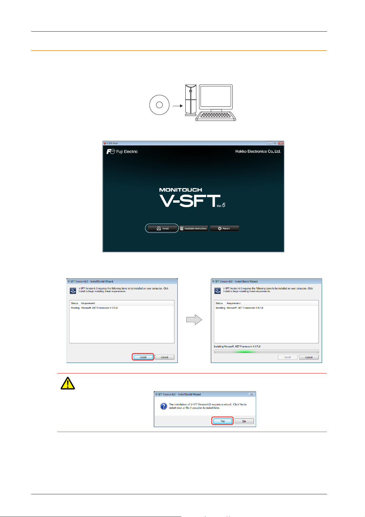
1. Startup Windows and place the “V-SFT Ver. 6 Disc 1” CD-ROM in the CD-ROM drive.
2. The following installation window is automatically displayed. Click [Install].
3. When Microsoft .NET Framework 4.0 or 4.5 is not installed on the computer, the following dialog box is displayed.
Click [Install]. Installation of .NET Framework 4.0 automatically starts.
After installation of .NET Framework 4.0, a message prompting you to reboot the computer may be displayed.
If displayed, be sure to reboot the computer.
1-2
Page 9
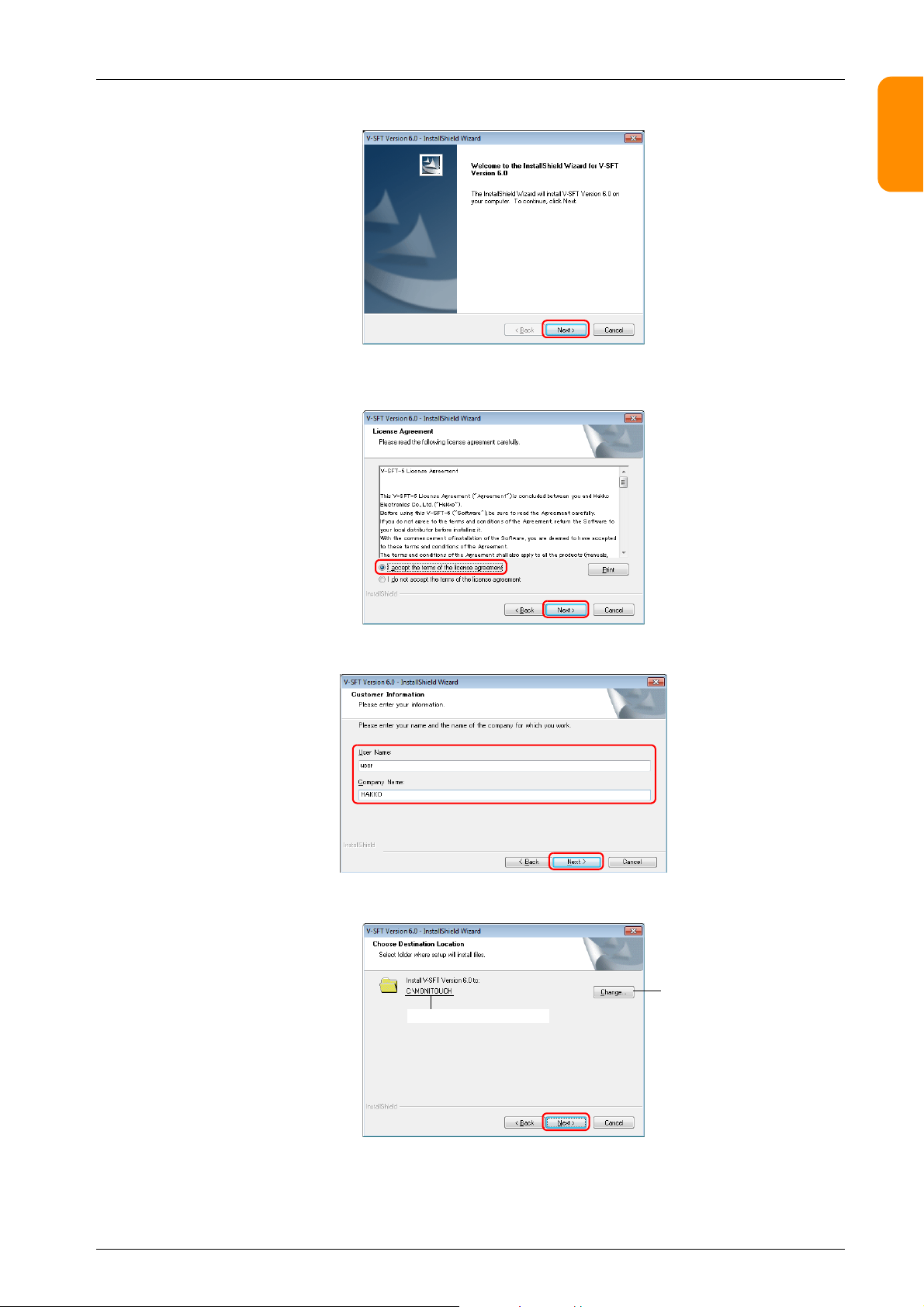
4. The following dialog box is displayed. Click [Next].
Installation location (default)
Click to change the
installation location
1.1 About V-SFT Version 6
1
2
5. The [License Agreement] dialog box is displayed.
Read the contents carefully, select [I accept the terms of the license agreement], and then click [Next].
6. The [Customer Information] dialog box is displayed. Enter your [User Name] and [Company Name], and then click [Next].
3
4
5
6
7. The [Choose Destination Location] dialog box is displayed. Click [Next].
7
8
9
10
1-3
Page 10
1 Introduction
Computer
Disc 2
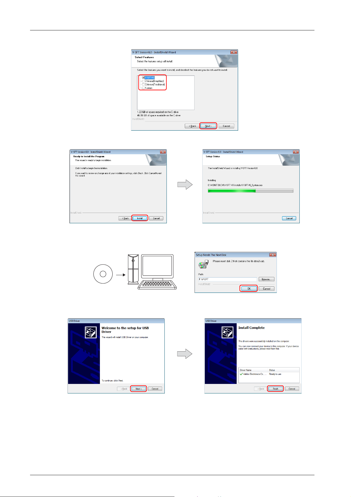
8. The following dialog box is displayed. Select a display language(s) to use on the V-SFT editor, and then click [Next].
9. The following dialog box is displayed. Click [Install]. Installation automatically starts.
10. The [Setup Needs The Next Disk] dialog box is displayed. Insert the “V-SFT Ver. 6 Disc 2” CD-ROM in the CD-ROM drive
and then click [OK]. Installation will resume.
11. When installation of V-SFT version 6 is complete, the [Welcome to the setup for USB Driver] dialog box is displayed.
Click [Next] to install the USB driver.
1-4
Page 11

1.1 About V-SFT Version 6
Selected:
The “README” file is
displayed.
Selected:
V-SFT Version 6 is started up.
12. After all installation processes are complete, the [Install Complete] dialog box is displayed. Click [Finish].
1
2
This completes the installation procedure.
3
4
5
6
7
8
9
10
1-5
Page 12

1 Introduction
USB driver, system programs, etc.
User files such as image f iles
“Vsft60.exe” application software etc.
1.1.3 Configuration of Installation Folder
The default installation location is as follows:
C:\MONITOUCH
“Common”, “User”, and “V-SFT V6” subfolders are created inside the “MONITOUCH” folder.
The “Vsft60.exe” application software is located in the “V-SFT V6” folder.
1.1.4 Uninstallation
The procedure for uninstalling V-SFT version 6 differs depending on your operating system.
For Windows Vista, 7, 8 or 8.1
Display the list of installed programs from [Control Panel] [Programs] [Programs and Features]. Select “V-SFT Version
6.0” from the list and click [Uninstall].
For Windows XP or XP 64 Edition
Display the list of installed programs from [Control Panel] [Add or Remove Programs]. Select “V-SFT Version 6.0” from the
list and click [Remove].
1-6
Page 13

2Starting
• Double-click the shortcut on the Desktop.
Start menu
• Click “V-SFTV6” in the Start menu.
• Double-click “Vsft60.exe” located in the installation folder.
Example: C:\MONITOUCH\V-SFT V6\VSft60.exe
[New]
Click to open an existing screen program file.
2.1 Creating a New Screen Program
2.1 Creating a New Screen Program
The procedures for starting the V-SFT and creating a new screen program are described.
1. Start V-SFT version 6 by any of the following methods.
1
2
3
4
2. The startup menu is displayed. Click [New].
5
6
7
8
When opening an existing screen program file, either click on [Open] in the Startup menu, or double-click on
the relevant screen program file.
9
10
2-1
Page 14

2 Starting
Port on V9
series unit
[PLC Properties] window
[Hardware
Setting]
window
Close
Device memory for switching the screen
using an external command
The first screen that is displayed
when entering RUN mode
3. Select the model for editing and device to connect and click [Finish].
4. The hardware settings and PLC properties are displayed. Configure the communication settings in the [PLC Properties]
window and then close the window. (Example: MITSUBISHI ELECTRIC QnU series CPU for PLC1)
5. Click [Control Area] in the [Hardware Setting] window and conf igure the following settings.
2-2
Page 15

2.1 Creating a New Screen Program
Screen configuration area
6. Click the [Close] button to close the [Hardware Setting] window. The [Screen [0] Edit] tab window is displayed.
1
2
7. Click [System Setting] [Multi-language setting].
8. The [Font Setting] window is displayed. Press the [Setting] button and set the font. Then click [OK] to close the window.
3
4
5
6
This completes the settings required to create a new screen program.
7
8
9
10
2-3
Page 16

2 Starting
Quick access toolbar
Catalog
Project
Function item
view window
Item list
Editing window
Application button
Status bar
Item settings window
Ribbon menu
2.2 Layout of V-SFT Ver. 6
The layout of the V-SFT editor is shown below.
2-4
Page 17

3 Screen Configuration
Numerical data entry
Device memory address
D100
page 3-8
Lamps
Device memory
addresses M0, M1
page 3-6
Switches
Device memory
addresses M0, M1
page 3-4
Numerical
data display
Character
display
Character entry
Device memory
addresses D101 to D104
page 3-8
Te xt
•M0: Momentary
•M1: Alternate
Release
Press
Press
Release
Press
The lamp turns on
while the switch is
pressed.
The lamp turns
on/off each time the
switch is pressed.
On
Off
On
Off
On
Keypad
Press
3.1 Screen Example
This section describes methods for configuring screen components.
For the procedure on creating a new screen program, refer to “2.1 Creating a New Screen
Program”.
3.1 Screen Example
Create the following example screen that uses switch output to turn lamps on and off and includes data entry parts.
•Screen No. 0
1
2
3
4
- Switch output (switch/lamp)
- Data entry: Keypad/keyboard display (numerical data display, character display)
5
6
7
8
9
10
3-1
Page 18

3 Screen Configuration
Comment
Background color
Enter a comment.
3.2 Registering Screen Comments and Changing the Background Color
Add a comment to the screen and change the background color.
1. Click [Screen Setting] [Screen Setting].
2. Add a comment and change the background color on the [Main] tab window.
3. Click [OK].
This completes the settings.
Comments can also be entered from the screen list.
Click [Home] [Screen List].
3-2
Page 19

3.3 Creating Text
Te xt
Select [Multi Text]
when entering two or
more lines.
Cursor
Start point
End point
Drag
MONITOUCH
Enter text.
Set the color and background
color of the text.
Set the text size.
3.3 Creating Text
Create the following part.
1. Click [Home] [Text] [Text]. The mouse cursor changes to a crosshair.
2. Drag from the start point to the end point on screen using the mouse. The specified area and a blinking cursor are
displayed on screen.
1
2
3
4
3. Enter text.
4. Click a location on the screen other than the text to accept the text entry.
5. Click the text to display its settings window. Change the text color and text size properties.
This completes the text creation process.
5
6
7
8
9
10
3-3
Page 20

3 Screen Configuration
Switches
Output
Switches
3.4 Creating Switches
Create the following parts.
1. Click [Home] [Switch] and place a switch on the screen.
2. Double-click on the switch to display its settings window. Configure each setting.
• [Char. Prop.]
Set the text to display on the switch.
•[Output Device]
Set the bit device memory for output and the operation to perform.
3. Click [Finish] to exit settings.
3-4
Page 21

4. Copy the created switch and configure the following settings.
Handle
Drag
3.4 Creating Switches
Copy method
•[Edit] [Copy]/[Paste]
• Right-click menu [Copy]/[Paste]
• [Char. Prop.]
•[Output Device]
1
2
3
4
5. Click [Finish] to exit settings.
A placed part can be enlarged or reduced. Click on the placed part to display its handles, and drag a handle with the mouse.
5
6
7
8
9
10
3-5
Page 22

3 Screen Configuration
Lamps
Input
OFF: Red
ON: Green
3.5 Creating Lamps
Create the following parts.
1. Click [Home] [Lamp] and place a lamp on the screen.
2. Double-click on the lamp to display its settings window. Configure each setting.
•[Style]
Set the ON/OFF colors of the lamp and the lamp device memory.
• [Char. Prop.]
Set the text to display on the lamp.
3-6
3. Click [Finish] to exit settings.
Page 23

4. Copy the created lamp and configure the following settings.
OFF: Red
ON: Green
3.5 Creating Lamps
Copy method
•[Edit] [Copy]/[Paste]
• Right-click menu [Copy]/[Paste]
•[Style]
• [Char. Prop.]
1
2
3
4
5. Click [Finish] to exit settings.
5
6
7
8
9
10
3-7
Page 24

3 Screen Configuration
Numerical data display
Character display
Entry from
keypad
Reading
(Display)
3.6 Entry Settings
Create the following parts.
3.6.1 Numerical Display
1. Click [Home] [Data Display] [Num. Display] and place a numerical display part on the screen.
2. Double-click on the numerical data display part to display its settings window. Configure each setting.
•[Contents]
•[Function]
3-8
3. Click [Finish] to exit settings.
Page 25

3.6.2 Character Display
3.6 Entry Settings
1. Click [Home] [Data Display] [Char. Display] and place a character display part on the screen.
2. Double-click on the character display part to display its settings window. Configure each setting.
•[Contents]
1
2
3
4
•[Function]
5
6
7
8
3. Click [Finish] to exit settings.
This completes the screen creation process.
Transfer the screen program to the V9 series unit and check the screen operation.
9
10
3-9
Page 26

3 Screen Configuration
3-10
Page 27

4 Transferring (via USB)
USB-A
USB-miniB
Computer
V9
Commercially available cable
Computer
V9
Commercially available
straight * or cross cable
* The V9 series suppor ts
Auto-MDIX.
D-sub 9pin
MJ1
Computer
V9
Hakko Electronics
“V-CP” cable
* If the computer is not equipped
with a serial port (D-sub 9-pin),
use a commercially available
USB-to-serial converter.
SD
USB
Memory
V9
SD card or USB flash drive
4.1 Overview
4.1 Overview
This section describes the procedure for transferring a screen program using a USB cable.
Screen programs can also be transferred by the following methods.
For details, refer to the V9 Series Operation Manual.
• Transfer via Ethernet
• Serial transfer
Ethernet
1
2
3
4
• Transfer via storage device
5
6
7
8
9
10
4-1
Page 28

4 Transferring
Computer
V9
With power on
The installation
wizard starts up.
Click to start installation.
4.2 Installing the USB Driver
A USB driver must be installed on the computer in advance to perform transfer using a USB cable.
Connect the V9 series unit (with power on) to the computer using a USB cable.
USB-miniB
For Windows Vista, 7, 8 or 8.1
The USB driver is automatically installed.
For Windows XP
Install the USB driver by the following procedure.
USB-A
4-2
Page 29

Confirming Successful Installation of the USB Driver
• Windows Vista, 7, 8, 8.1 • Windows XP
4.2 Installing the USB Driver
When the driver has been installed successfully, “Operation Panel - Operation Panel USB Driver” is displayed in the [Device
Manager] window.
This item will disappear when the USB connection is disconnected.
If [Other Device] or a mark other than shown above is displayed even while connected via USB, the USB driver is not
recognized. If this happens, uninstall the USB driver and reinstall it.
When USB Driver Installation Fails
If installation of the USB driver has failed, reinstall it.
1
2
3
4
5
Install by double-clicking “USBDriverInstaller.exe” in the “C:\MONITOUCH\Common\Driver” folder.
6
7
8
9
4-3
10
Page 30

4 Transferring
USB-A
USB-miniB
Computer
V9
Commercially available cable
Tra ns fe r
Screen program
Unselected
Computer (V-SFT) V9 series unit (Local mode) *
System menu
4.3 Transfer Procedure (Downloading from PC to V9 Series Unit)
This section explains how to transfer a screen program from the computer to the V9 series unit.
1. Click [Transfer] [Download] to display the [Transfer] window.
2. Configure the following settings.
Simulator
If a PLC is not available during debugging, use the simulator to check screen operation with only the V9 series unit.
The simulator runs on the computer and acts as a PLC. For details, refer to the V9 Series Training Manual Beginner's Guide.
3. Click [PC ].
A screen program is transferred and written to the V9 series unit. The following screens are displayed respectively during
transfer.
* If the V9 series unit does not automatically switch to Local mode and transfer does not start, manually switch to Local mode and execute
the transfer.
To switch to Local mode, press the [SYSTEM] switch and press [Local] on the system menu displayed at the top of the screen.
4-4
- When the [Local] switch is not displayed (with [Mode Switch Prohibited] selected):
Display the system menu and hold down the [F1] switch and the [F7] switch (max. 30 seconds).
- When the system menu is not displayed (with [System Switch Prohibited] selected):
Hold down the [SYSTEM] switch and the [F7] switch (max. 30 seconds).
Page 31

4.4 Connecting to a PLC
V9
Communication cable
PLC
Checking connection with PLC
(A splash screen can be set by
preference. *)
* For details, refer to V9 Series
Reference Manual 2.
The created screen program is
displayed.
The V9 series unit will switch to RUN mode once
the cause of the error is resolved.
* For details on errors, refer to the V9 Series
Troubleshooting/Maintenance Manual.
4.4 Connecting to a PLC
Connect the V9 series unit with a PLC and switch to RUN mode.
1. Use a communication cable to connect the V9 series unit with a PLC.
For details of wiring, refer to the V9 Series Connection Manual.
2. If communication is established, the created screen program (in RUN mode) is displayed.
If the Local mode screen or a communication error screen is displayed, press the switch indicated below to switch to RUN
mode.
1
2
3
4
5
6
7
8
This completes the necessary settings.
9
10
4-5
Page 32

4 Transferring
4-6
 Loading...