

Page 1

– 1 –
Thank you for your purchasing "Fuji Digital Temperature Controller."Please check that the product is exactly the
one you ordered and use it according to the following instructions. (Please refer to a separate operation manual
for details.) Dealers are cordially requested to ensure the delivery of this Instruction Manual to hands of the endusers.
NOTICE The contents of this document may be changed in the future without prior notice.
We paid the utmost care for the accuracy of the contents. However, we are not liable for direct and
indirect damages resulting from incorrect descriptions, omission of information, and use of information in this document.
Read before using................................................ 3
Index ................................................................ 7
1. Installation/mounting ...................................... 8
2. Wiring............................................................. 9
3. Usage............................................................. 10
4. Display and operation .................................... 11
5. Setting methods of temperature and
paramenters............................................ 12
1st block parameter........................................ 12
2nd block parameter ...................................... 13
3rd block parameter ....................................... 14
6. Function ......................................................... 15
6-1 ON/OFF control ...................................... 15
6-2 Auto-tuning (A T)...................................... 16
6-3 Self-tuning............................................... 17
6-4 Alarm function [option] ............................ 19
6-5 Ramp/soak function [option] ................... 21
6-6 Communication function [option]............. 22
6-7 Digital input (DI function) [option]............ 23
6-8 Other functions ....................................... 24
7. Setting of input type and control algorithm..... 25
8. Error indications ............................................. 27
[Table1] Input type code ....................................... 28
[Table2] Control output action code...................... 28
[Table3] Input range (Standard range) ................. 29
[Table4] Alarm action type code........................... 30
PXR Model Code Configuration ........................... 31
Specification......................................................... 32
CONENTS
Instruction Manual
Micro-controller X
Model: PXR4
INP-TN1PXRa-E
Fuji Electric Co., Ltd.
Head Office
11-2, Osaki 1-chome, Shinagawa-ku, Tokyo, 141-0032 Japan
http://www.fujielectric.co.jp
Fuji Electric Instruments Co., Ltd.
Sales Div. International Sales Dept.
No.1, Fuji-machi, Hino-city, Tokyo, 191-8502 Japan
Phone : +81-42-585-6201,6202
Fax : +81-42-585-6187,6189
http://www.fic-net.co.jp
Page 2
– 2 –
The related documents
For details, refer to the following documents.
Before using the controller, check if the type and specifications are as ordered. (A Table of Model code configuration is given in Page 4).
Check that all of the following accessories are included in the package box.
Check of specifications and accessories
· Temperature controller 1 unit
· Instruction manual 1 copy
· Mounting bracket 1 pce.
· I/V unit (250Ω resistor) 1 pce. (4-20mA DC input type only)
· Terminal cover 1 pce. (optional item seperately ordered.)
Contents Name
Operation method
MICRO-CONTROLLER X (Model : PXR)
OPERATION MANUAL
Communication functions
COMMUNICATION FUNCTIONS (MODBUS)
INSTRUCTION MANUAL
Specifications
Catalogue
Name
ECNO : 406
INP-TN512642-E
ECNO : 1136
Page 3
– 3 –
1. Warning
1.1 Installation and wiring
• This controller designed to be installed at the following conditions.
• The controller must be installed such that with the exception of the connection to the mains, creepage
and clearance distances shown in the table below are maintained between the temperature probe
and any other assemblies which use or generate a voltage shown in the table below.
Failure to maintain these minimum distances would invalidate the EN 61010 safety approval.
Operating temperature -10 to +50 [°C ]
Conforming to IEC1010-1
Installation category II
Pollution degree 2
Operating humidity 90%RH or less (Non condensation)
Up to 50Vrms or Vdc
Voltage used or generated
by any assemblies
Clearance
(mm)
Creepage
(mm)
0.2
Up to 150Vrms or Vdc 0.5
Up to 300Vrms or Vdc 1.5
Above 300Vrms or Vdc Contact with our sales office.
Up to 100Vrms or Vdc 0.2
1.2
1.6
3.0
1.4
Before using this product, the user is requested to read the following precautions carefully to ensure
the safety . Safety precautions must be taken by every user to prevent accidents.
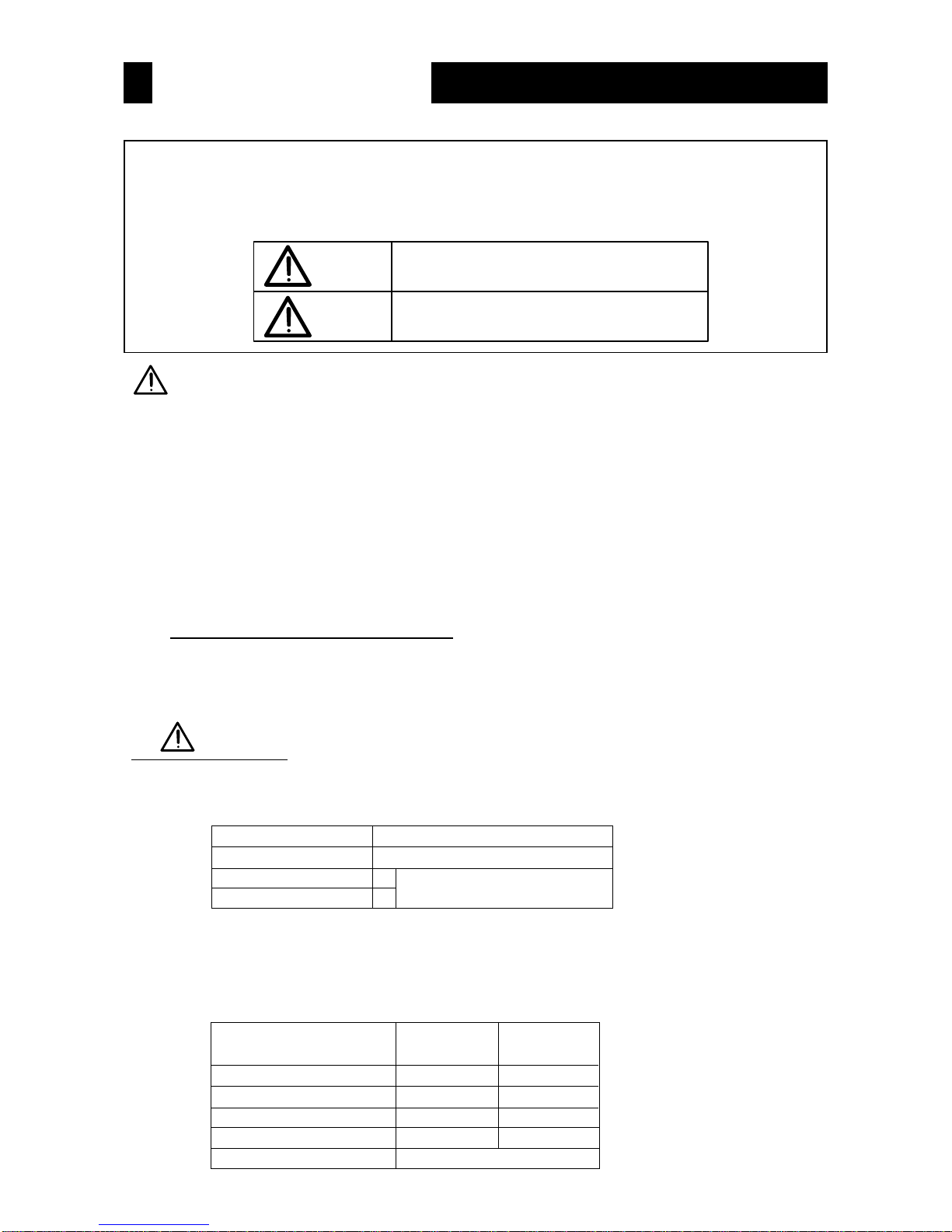
The safety requirements are classified into "warning" and "caution" according to the following
interpretations :
Warning
Suggesting that the user's mishandling can
result in personal death or serious injury.
Caution
Suggesting that the user's mishandling can result
in personal injury or damage to the property.
WARNING Over-temperature Pr otection
Any control system should be designed with prior consideration that any part of the system has potential to
fail.
In case of temperature controlling, a continuance of heating on should be regarded as the most dangerous
state.
The followings are the most probable causes of inducing continuance of heating on:
1) The failure of the controller with heating output constantly on
2) The disengagement of the temperature sensor out from the system
3) The short circuit in the thermocouple wiring
4) V alve or switch contact point outside the system is locked to keep heating on
In any application in which it is apprehended that physical injury or destruction of equipment might occur,
please install an independent safeguard equipment to prevent over-temperature which shut down the heating
circuit, and for additional safety, we recommend this equipment to have its own temperature sensor.
The alarm output signal of the controller is not designed to work as protective measures when the controller
is in failure condition.
Safety PrecautionsRead before using
Page 4
– 4 –
• If the voltage shown above exceeds 60Vdc (i.e. hazardous voltage), the basic insulation is required
between all terminals of this controller and the ground, and supplementary insulation is required for
the alarm output.
Isolation class of this controller is as shown below. Be sure to check that the isola-tion class of the
controller satisfies your requirements before installan.
• If there is a danger of a serious accident resulting from a failure or a defect in this unit, provide the unit
with an appropriate external protective circuit to prevent an accident.
• The unit is normally supplied without a power switch and fuses.
Make wiring so that the fuse is placed between the main power supply switch and this controller. (Main
power supply: 2 pole breaker, fuse rating: 250V, 1A)
• When wiring the power supply terminal, use vinyl insulated 600 volt cable or equivalent.
• To avoid the damage and failure of controller, supply the power voltage fitting to the rating.
• T o avoid an electric shock and controller failure, do not turn ON the power before all wiring is completed.
• Be sure to check that the distance is kept to avoid electric shock or firing before turning the power ON.
• Keep away from terminals while the circuit is energized in order to avoid an electric shock and a
malfunction.
• Never attempt to disassemble, fabricate, modify, or repair this unit because tampering with the unit
may result in a malfunction, electric shock, or a fire.
1.2 Maintenance precautions
• Be sure to turn off the power before this controller is installed or removed in order to avoid an electric
shock, malfunction, and fault.
• Regular maintenance is recommended a longer service life of this controller. Some parts of this
controller have a limited life span, or they will be deteriorated with the lapse of time.
• One-year warranty is guaranteed for this unit including accessories, provided that the controller is
properly used.
Mains (Power source) Measured value input, CT input
Control output1 (relay output) Internal circuit
Control output2 (relay output) Control output1 (SSR drive output / Current output)
Alarm outout (AL1)
Alarm outout (AL2) Communication (RS-485) circuit
Heater burnout alarm output (HB) Digital input (DI).
: Basic insulation,
: Non-insulation,
: Functional insulation
Page 5
– 5 –
2. Warning
2.1 Cautions on installation
Avoid the following places for installation.
• a place where the ambient temperature may reach beyond the range of from 0 to 50∞C while in
operation.
• a place where the ambient humidity may reach beyond the range of from 45 to 85% RH while in
operation.
• a place where a change in the ambient temperature is so rapid as to cause
condensation.
• a place where corrosive gases (sulfide gas and ammonia gas, in particular) or combustible gases are
emitted.
• a place where the unit is subject directly to vibration or shock.
• a place exposed to water oil, chemicals,steam and vapor.
(if immersed with water, take the inspection by sales office to avoid an electrical leakage and firing )
• a place where the unit is exposed to dust, salt air, or air containing iron particles.
• a place where the unit is subject to intereference with static electricity, magnetism, and noise.
• a place where the unit is exposed to direct sunlight.
• a place where the heat may be accumulated due to the radiation of heat.
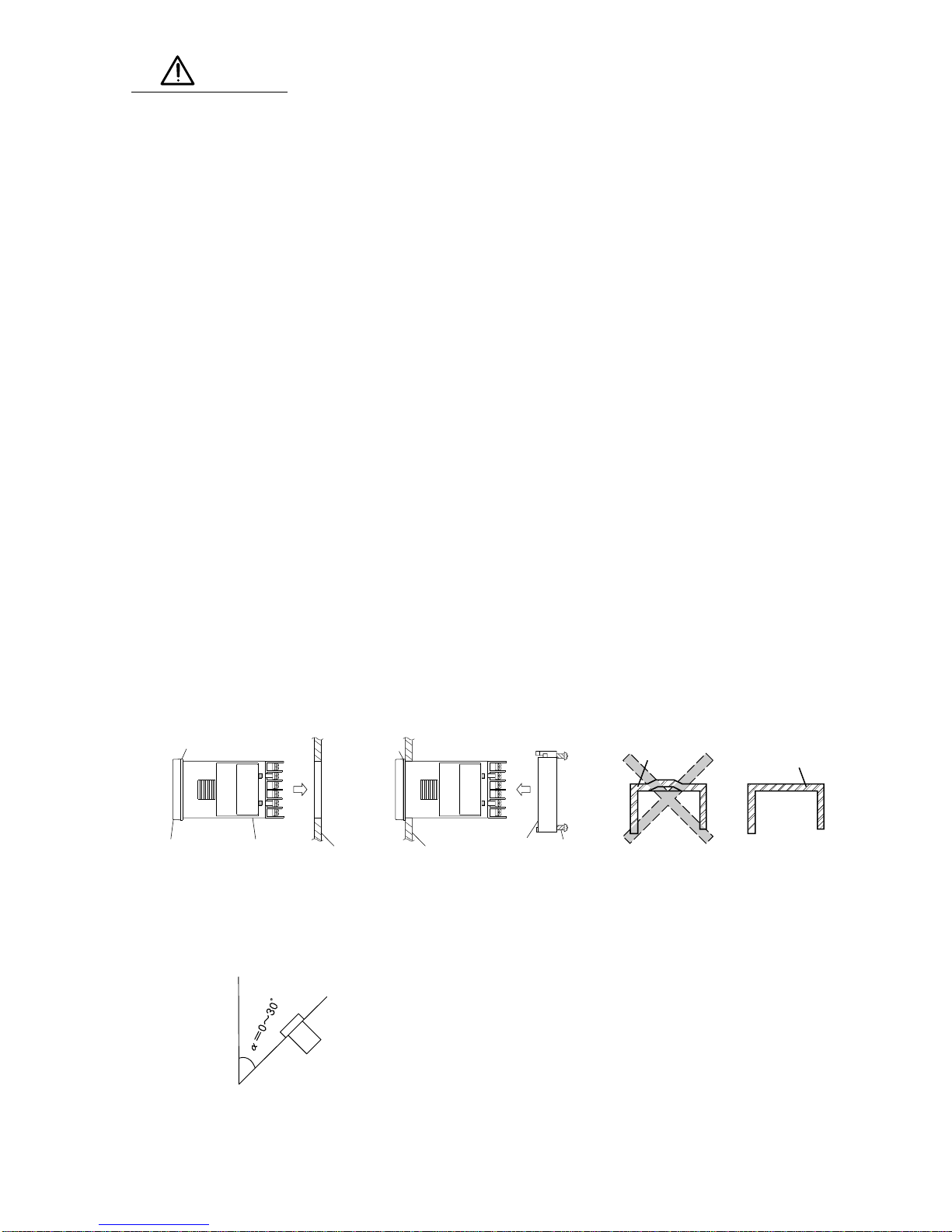
2.2 Caution on installation on panel
• Insert the mounting bracket (accessory) from the rear side until the main unit is securely fit into the
panel. If there should be a play , tighten two screws lightly until the play is eliminated. (Do not tighten
the screws excessively because the mounting bracket can be removed from the stopper by the force.)
• The front side of this controller conforms to NEMA 4X(equivalent with IP66). To ensure the
waterproofness between the instrument and the panel, use packings that are provided as accessories
in the following manner: (The improper fitting of packings will ruin the waterproofness.)
q As shown in Figure 1, fit a packing to the case of the unit and then insert it in the panel.
w Tighten screws on the fixing frame or fixtures so that no gaps are given between the front of
controller and packing and between panels. Check that there are no deviation and deformation of
packing as shown in Fig.3.
No. 000001T
PXR4TAA1-1YM00-D
MFD 2000-04
No. 000001T
PXR4TAA1-1YM00-D
MFD 2000-04
Figure 1 Figure 2
Unit Unit
Front
Case
Panel
PackingPacking
Panel
Mounting
bracket
Screw
Figure 3
Packing
Packing
Case
Case
(Bad) (Good)
Standard : Vertical mounting, flush on the panel. (The controller is horizontal.)
When mounting the controller on tilted surface, the maximum tilt angle is 30° (degree) from virtical.
(Caution)
• Don’t block the openings around the controller, or radiation effect will be reduced.
• Don’t block the ventilation openings at the top of the terminal block.
Page 6

– 6 –
2.3 Precautions in wiring connection
• For the thermocouple sensor type, use thermocouple compensation wires for wiring.
For the RTD type, use a wiring material with a small lead wire resistance and no resistance differentials
among three wires.
• Keep input lines away from power line and load line to avoid the influence from noise induced.
• For the input and output signal lines, be sure to use shielded wires and keep them away from each
other.
• If a noise level is excessive in the power supply , the additional installation of an insulating transformer
and the use of a noise filter are recommended. (example: ZMB22R5-1 1 Noise Filter manufactured by
TDK)
Make sure that the noise filter is installed to a place such as a panel that is properly grounded. The
wiring between the noise filter output terminal and the instrument power supply terminal should be
made as short as possible. None of fuses or switches should be installed to the wiring on the noise
filter output side because the filter effect will be degraded by such a installation.
• A better anti-noise effect can be expected by using stranded power supply cable for the instrument.
(The shorter the stranding pitch is, the better the anti-noise effect can be expected.)
• For the unit with an alarm against a failure (burn-out) in the heater, use the same power line for
connection of the power supplies for the heater and the controller.
• A setup time is required for the contact output when the power is turned on. If the contact output is
used as a signal for an external interlock circuit, use a delay relay at the same time.
• Use the auxiliary relay since the life is shortened if full capacity load is connected to the output relay .
SSR/SSC drive output type is preferred if the output operations occur frequently.
[Proportional interval] relay output: 30 seconds or more, SSR/SSC: one second or more]
• If inductive load such as magnetic switches connected as a relay output load, it is recommended to
use Z-Trap manufactured by Fuji Electric to protect a contact from switching serge and keep a longer
life.
Model : ENC241D-05A (power supply voltage: 100 V)
ENC471D-05A (power supply voltage: 200 V)
Where to install : Connect it between contacts of the relay control
output.
Example)
• The SSR/SSC-driven output, an output of 4 to 20 mA DC, are not electrically insulate from internal
circuits.
Use a non-grounded sensor for resistance bulb or thermocouple.
2.4 Requirement for key operation/operation in abnormalities
• Prior to the operation, be sure to check alarm functions, since a failure in the proper setting will result
in a failure in the proper output of an alarm in case of an abnormality.
• A display of UUUU or LLLL will appear in case of a break in the input. Be sure to turn off the power
when a sensor is replaced.
2.5 Others
• Do not use organic solvents such as alcohol and benzine to wipe this controller. Use a neutral detergent
for wiping the controller.
1 7
13
2 8
14
3 9
15
4
10 16
5
11 17
6
12 18
Z-Trap connection
Page 7

– 7 –
<Reference items>
<Description>
Error indication
8
Power on
Wiring
2
Usages
3
Display and operation
4
Setting method of temperature and parameters
5
Functions
6
Setting of input type and control method.
7
Operation
Installation/mounting
1
Confirming type specification
• Confirming that the delivered
controller is equal to the ordered
one.
• Outline dimensions
• Panel cutout dimensions
• Mounting method on the panel
• Set value change method
• Basic operation method
• List of parameters
• List of input/output/alarm codes
• Setting of input type and ranges
• Selecting of control method
• Terminal connection diagram
*Note
(Note) *To start the operation, wait for about 30 minutes after the power-on for
warm up.
Index.
Page 8
– 8 –
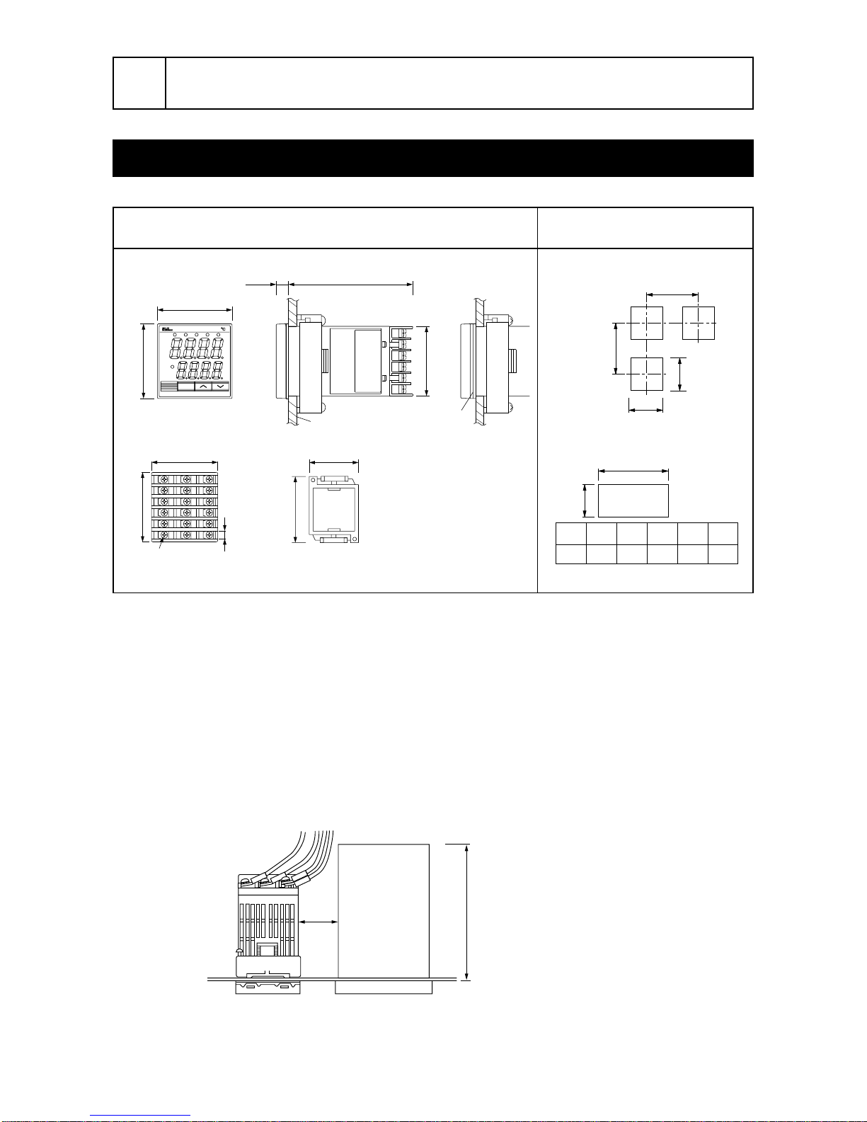
1 Installation/mounting
Outline and Panel Cutout Dimensions (Standard type/ Waterproof type)
Note 1
Caution on side by side installation
• With the power supply of 200 V AC or more, a maximum ambient temperature is 45˚C.
(It is recommended to use a fan for cooling.)
Cautions on wiring
• Wiring should be started from the left side terminal (No. 1 to No. 6).
• Use crimped terminals matched to the screw size. Tightening torque should be 0.8 Nm (Since the
case is made of plastic, do not tighten excessively).
• Do not connect anything to terminals not used.
No. 000001T
PXR4TAA1-1YM00-D
MFD 2000-04
AL2AL1C1 C2 AL3
SEL
PXR-4
SV
PV
48
44.8
44.8
79.88
48
Mounting bracket
Panel
Panel thickness 1 to 8mm
Packing
48
44.8
57
6.2
Terminal screw M3×6
13
16
17
18
14
15
7
8
10
11
12
9
1
2
4
5
6
3
63 or more
73 or more
+0.5
a -0
Number
of units
23456
a 93 141 189 237 285
45
+0.5
0
45
+0.5
0
45
+0.5
0
For side by side installation
Note) See the Note1.
Outline dimensions
Panel cutout dimensions
(Unit : mm)
When there is another instrument (larger than 70mm) or a wall on the right side of this controller, be sure
to install the controller keeping a space of more than 30mm.
30 min.
70 or more
Page 9
– 9 –
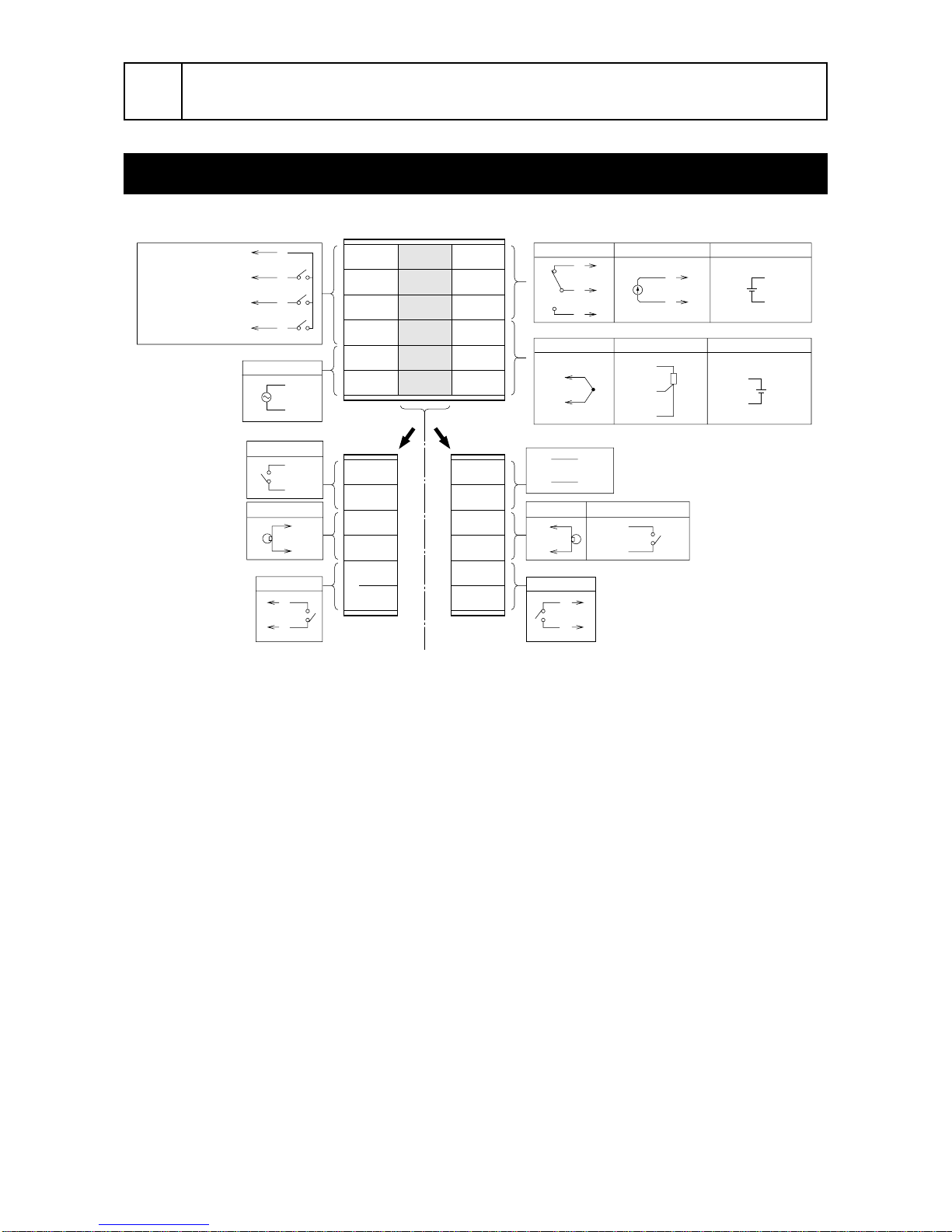
2 Wiring
Terminal Connection Diagram (100 to 240 Vac)
· Common
Relay output
Thermocouple Resistance valve Current/Voltage
Current output
uq!3
iw!4
oe!5
!0r
q
w
e
r
!6
!1t!7
!2y
t
y
!8
· Alarm output1 (AL1)
· Alarm output2 (AL2)
· Heater break
alarm output (AL3)
AC100-240V
Digtal input
CT input
CT input Digtal input
50/60Hz
(+)
(-)
SSR/SSC drive output
Control output1
Alarm output
!3
!4
Note1 : Check the power supply voltage before installation.
Note2 : Connect the I/V unit (250Ω resistor) (accesory) between the terminal !7 and !8 in case of
currert input.
u
i
u
i
o
!0
o
!0
!1
!2
u
i
u
i
o
!0
o
!0
o
!0
!1
!2
!1
!2
Communicaton (RS485)
Power supply
+
-
!77
!8
Signal input
A
B
B
!6
!77
!8
Control output 2
!3
!4
+
-
Relay output
Control output 2
!1
!2
Relay output
!77
!8
(Note2)
!3
!4
!5
(
Note1
)
Page 10
– 10 –
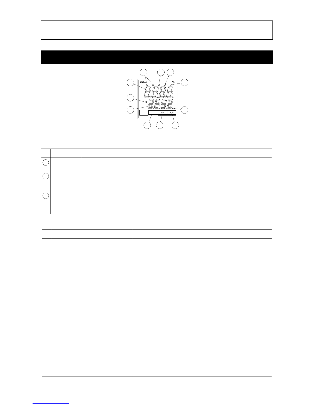
3 Usage (Read before using)
Name of Functional Parts and Functions
AL2AL1C1 C2 AL3
SEL
PXR-4
SV
PV
1
2
3
S1 S2 S3
4
8
765
Model : PXR4
Name Function
Select key The key shifting to the 1st, the 2nd or the 3rd block parameter, switching the display
between parameter and the data at the 1st, the 2nd and the 3rd block.
Setting keys
S1
Down key · The numerical value is decreased by pressing the key once. The numerical value
keeps on decreasing by pressing the key continuously.
· For searching parameters within the 1st, tne 2nd and the 3rd block.
S3
Up key · The numerical value is increased by pressing the key once. The numerical value
keeps on increasing by pressing the key continuously.
· For searching parameters within the 1st, the 2nd and the 3rd block.
S2
Name Function
Process value (PV)/parameter
name display
1) Displays a process value (PV).
2) Displays the parameter symbols at parameter setting mode.
3) Displays various error indications
(refer to the 8, Error indications).
Display/Indication
q
Set value (SV)/parameter setting
display
1) Displays a set value (SV).
2) Display the parameter settings at parameter setting mode.
3) Flickers at Standby mode.
4) Displays the set value (SV ) and “SV-1” alternately when
the SV switching function is used.
e
Set value (SV) indication lamp The lamp is lit while a set value (SV) is displayed.
w
Auto-tuning/self-tuning indicator The lamp flickers while the PID auto-tuning or the self-tuning
is being performed.
r
Control output indication lamp C1 : The lamp is lit while the control output 1 is ON.
C2 : The lamp is lit while the control output 2 is ON.
t
Alarm output 1 (AL1)
indication lamp (Note 1)
The lamp is lit when the alarm output 1 is activated. It flickers
during ON delay operation.
y
Alarm output 2 (AL2)
indication lamp (Note 1)
The lamp is lit when the alarm output 2 is activated. It flickers
during ON delay operation.
u
Heater break alarm output (AL3)
indication lamp (Note 1)
The lamp is lit while the heater break alarm output is ON.
Note 1) Control output 2 and alarm function are optional.
i
Page 11

– 11 –
4 Display and operation
AL2AL1C1 C2 AL3
SEL
PXR-4
SV
PV
AL2AL1C1 C2 AL3
SEL
PXR-4
SV
PV
· To perform standby operation, set "STby" as ON in the
1st block parameter.
· Standby mode:
(Output) Control outputs (1 and 2) and alarm outputs (all) are not provided. However,
depending on setting of "P-n1", control action, control outputs are provided at the
abnormal input.
No alarm output is provided at standby mode, even in (Fault-condition).
Standby mode
Operation mode
Parameter setting mode
Switching by the key
SEL
1
Change of set value (SV)
2
Shift to the 1st, 2nd and 3rd block parameter
To shift to the other blocks, press the key.
When the SV lamp is lit, the set value (SV) is displayed at the lower line.
The set value (SV) can be changed.
After the data setting, the data are registered
automatically in 3 seconds.
Depending on the pressing time of key,
you can select the block to shift.
SEL
SEL
SEL
pressing time Shifting block
About 1 sec pressing 1st block
About 3 sec pressing 2st block
About 5 sec pressing 3st block
Caution
Caution
Caution
Caution
(Control) Control is not performed.
(Display) SV display flickers.
(Setting) SV and parameter settings are able to perform.
Be careful since the equipment does not provide output of the alarm of
the main unit abnormality during the standby operation.
The SV display does not flicker while the 1st, 2nd and
3rd block parameters are displayed.
Switching by 1st block
STby settings
AL2AL1C1 C2 AL3
SEL
PXR-4
SV
PV
AL2AL1C1 C2 AL3
SEL
PXR-4
SV
PV
SEL
SEL
SEL
SEL
SEL
SEL
AL2AL1C1 C2 AL3
SEL
PXR-4
SV
PV
1
Press the
once.
Press the for 2 sec.
Parameter selection
Parameter setting procedure
Select a parameter you want to
set by pressing the or
key.
3
3
1 2
To shift to Operation/Standby
mode, press the key for 2 sec.
2-1
Press the key to allow the
parameter to change.
(Under the changing condition,
the parameter set value flickers).
2-2
Pressing the or key, to
change the parameter set value.
2-3
After the parameter has been
changed, press the key
for registration.
Parameter settings
Shift to operating condition
Parameter search.
1
Registers
parameter set
value, returning
to the parameter shift mode .
Operation mode
Press the . Press the .
Parameter change.
Increases parameter set value
Decreases parameter set value
By repeating the same procedure, the parameters
can be displayed according to the parameter list
shown in 5, Setting methods of temperature and
parameters.
Page 12

– 12 –
5 Setting methods of temperature and paramenters
Standby
AL2AL1C1 C2 AL3
SEL
PXR-4
SV
PV
Control output status
Alarm status
PV value
indication
SV value
indication
When the set value (SV) is displayed at the lower line, the SV lamp is lit.
AL2AL1C1 C2 AL3
SEL
PXR-4
SV
PV
Operation/Standby mode
SV value
indication
flickers.
SEL SEL
Operation
Parameter
display symbol
Parameter
Standby settings
Description of contents
Default
setting
Remarks
STbY
ProG
LACH
AT
TM-2
AL1
A1-L
A2-L
A2-H
LoC
TM-1 Timer 1 display
Timer 2 display
Alarm 1 low limit
set value
Alarm 1 set value
(appears only with alarm action type 16 to 31).
Setting range: Note 1
Alarm 1 high limit
set value
(appears only with alarm action type 1 to 10).
Setting range: Note 1
Alarm 2 set value
10
10
A1-H
AL2
10
10
0
Switches RUN or Standby of the control.
ON: Control standby (output: OFF, alarm: OFF)
OFF: Control RUN
OFF: stop, rUn: Start, HLd: status hold
0: Stop, 1: Standard AT start, 2: Low PV type AT start
OFF
Alarm latch cancel Releases alarm latch.
1: Alarm latch release
0
Ramp/soak control
OFF
Auto-tuning
Time displays remining time at the timer mode.
(appears only with alarm action type 1 to 10).
Setting range: Note 1
(appears only with alarm action type 16 to 31).
Setting range: Note 1
(appears only with alarm action type 16 to 31).
Setting range: Note 1
Alarm 2 high limit
set value
(appears only with alarm action type 16 to 31).
Setting range: Note 1
Alarm 2 low limit
set value
Setting of key lock status. Key lock
10
0
10
10 Table 3
(Page 4)
Table 3
(Page 4)
Table 3
(Page 4)
Table 3
(Page 4)
Table 3
(Page 4)
Table 3
(Page 4)
10
All parameters
Front key
0
1
2
3
4
5
Comm-
unication
SV
Front key Comm-
unication
Note 1) Setting range :0 to 100%FS (in case of absolute value alarm)
100 to 100%FS (in case of deviation alarm)
Note 2) Never set "TC" / "TC2" = 0
· Some parameters may not be displayed on the screen, depending upon the types.
1st block parameter
: Setting enable, : Setting disable
Press for about 1 sec. Press for about 2 sec.
Page 13

– 13 –
Standby
AL2AL1C1 C2 AL3
SEL
PXR-4
SV
PV
Control output status
Alarm status
PV value
indication
SV value
indication
When the set value (SV) is displayed at the lower line, the SV lamp is lit.
AL2AL1C1 C2 AL3
SEL
PXR-4
SV
PV
Operation/Standby mode
SV value
indication
flickers.
SEL SEL
Operation
Parameter
Proportional band
Description of contents
Default
setting
Remarks
P
I
D
TC
TC2
CooL
db
P-SU
P-dP
ALM1
ALM2
HYS
Hysteresis for ON/OFF contorol
Cycle time (control output 2)
Deadband/overlap
Proportional band
coefficient on cooling side
Input type code
Lower limit of input range
As ordered
As ordered
P-n2
P-SL
As ordered
As ordered
0/5
0/9
5.0
Derivative action time
60.0
Integral time (reset)
240
Cycle time (control output 1)
Setting types of alarm action (Setting range: 0 to 34)
Setting of decimal point
position
PVOF
0
PV offset
Type of alarm 1
Upper limit of input range
Type of alarm 2
1
30/2 Note 2
30
1.0
0.0
PTn
1
Selects the ramp/soak execute type.
1: Executes 1st to 4th segment.
2. Executes 5th to 8th segment.
3. Executes 1st to 8th segment.
Ramp/soak execute type
SV-1
to
SV-8
0%FS
Sets the target SV for each ramp segment.
(Setting range: 0 to 100%FS)
Ramp target SV-1 to SV-8
TM1r
to
TM8r
0.00
Sets the time for each ramp segment.
(Setting range: 0 to 99 hours and 59 minutes)
1st ramp segment time to
8th ramp segment time
TM1S
to
TM8S
0.00
Sets the time for each soak segment.
(Setting range: 0 to 99 hours and 59 minutes)
1st soak segment time to
8th soak segmentl time
STAT
-
Ramp/soak status
Shift the display of process value (PV).
(Setting range: -10 to 10%FS)
Displays the current Ramp/Soak status.
No setting can be made.
Setting range: 0.0 to 999.9%
ON/OFF control when "P" = 0
Setting range: 0 to 3200 sec.
No integral action when "I" = 0
Setting range: 0.0 to 999.9 sec.
No derivative action when "d" = 0
Sets cycle time of control output 1.
(Setting range: 1 to 150 sec)
Setting range: 0 to 50% FS
Sets cycle time of control output 2.
(Setting range: 1 to 150 sec)
Sets the proportional band coefficient on the cooling side.
(Setting range : 0.0 to 100.0)
ON/OFF control when "Cool" = 0
Shifts the output value on the cooling side.
(Setting range: -50.0 to 50.0%)
Lower limit of input range
(Setting range: -1999 to 9999)
Upper limit of input range
(Setting range: -1999 to 9999)
Type of input Table 1
(Page 4)
Table 2
(Page 4)
Table 2
Table 2
(Page 4)
Table 3
(Page 4)
Table 3
(Page 4)
Select a decimal point position of display.
(Setting range: 0 to 2)
. .
"1"
0 : No decimal point
"2"
CTrL
PID
Type of control algorithm.
(Setting range: PID, FUZZY, SELF)
Control algorithm
P-dF
Time constant of input filter
5.0
Time constant (Setting range: 0.0 to 900.0 sec.)
2nd block parameter
Parameter
display symbol
Note 2
Table 2
(Page 4)
Press for about 3 sec. Press for about 2 sec.
Page 14

– 14 –
Standby
AL2AL1C1 C2 AL3
SEL
PXR-4
SV
PV
Control output status
Alarm status
PV value
indication
SV value
indication
When the set value (SV) is displayed at the lower line, the SV lamp is lit.
AL2AL1C1 C2 AL3
SEL
PXR-4
SV
PV
Operation/Standby mode
SV value
indication
flickers.
SEL SEL
Operation
Parameter
Control action
Description of contents
Default
setting
Remarks
P-n1
A1hY
A2hY
dLY2
A1oP
A2oP
dLY1 ON delay time of
alarm 1
ON delay time of
alarm 2
Additional function
of alarm 2
Additional function
of alarm 1
Lower limit of SV
(Setting range: 0 to 100%FS)
Lower limit of SV
Upper limit of SV
(Setting range: 0 to 100%FS)
Upper limit of SV
0%FS
100%FS
SV-L
SV-H
0 Table 4
(Page 4)
6-7
(Page 3)
6-6
(Page 3)
Hysteresis for
alarm 1
Sets ON-OFF hysteresis for alarm output.
(Setting range: 0 to 50%FS)
1
Hysteresis for
alarm 2
ON delay time setting for alarm output
(Setting range: 0 to 9999 sec)
Additional function of alarm output
(Setting range: 000 to 111)
Alarm latch (1:use, 0:not use)
Alarm of error status (1:use 0:not use)
De-energized (1:use 0:not use), Note 3.
0
1
0
000
000
dl-1
CT
-
CT (Current Transformer) input valueCT input value
0(OFF)
Selects digital input 1 (DI1) function
(Setting range: 0 to 12)
DI1
function
STno
1
Communication station No. (Setting range: 0 to 255)Station No.
CoM
0
Parity setting
Parity setting. Baud rate is fixed at 9600 bps.
(Setting range: 0 to 2)
PYP
34
Code for PYP input
type
Input type code used when communicating with PYP.
See the OPERATION MANUAL
(Initial value: K: 0 to 400 C)
dSP1
to
dSP13
Parameter mask Specifying parameter mask
Selects the control action.
Hb
0.0
Sets current value to detect the heater disconnection
(Setting range: 1.0 to 50.0A, 0: OFF)
HB alarm set value
Parameter
display symbol
3rd block parameter
Note 3) De-energized: Contact opens when the alarm "ON".
Press for about 5 sec. Press for about 2 sec.
Page 15

– 15 –
6 Functions
• At ON/OFF control mode,output signal is as shown below.
Set parameter “P” = 0 for selecting the ON/OFF control mode.
Set the hysteresis to avoid chattering.
(Default setting: Hys = 1)
• Parameter setting and operation example
Example 1 : Reverse operation
Parameter
P
P-n1
HYS
Relationship of
PV and SV
PV > SV
PV < SV
Output
OFF
ON
Setting value
0.0
0 (or 1)
Any value
PV
when PV
increases
PV
when PV
decreases
HYS
SV
PV
when PV
increases
PV
when PV
decreases
HYS
SV
ON
ON
ON
ON
Example 2 : Direct operation
Parameter
P
P-n1
HYS
Setting value
0.0
2 (or 3)
Any value
6-1 ON/OFF control
Page 16

– 16 –
Setting code (AT)
012
When auto-tuning
is cancelled or not
performed.
Standard type
(auto-tuning at SV)
Low PV type (autotuning at 10%FS
below SV.)
Start of AT
End of AT
PV
PID control
Start of AT
End of AT
PV
PID control
SV-10%FS
Set value (SV)
Set value (SV)
q Standard type (AT=1)
(a) The P.I.D. parameter calculated by auto-tuning remains even if the power is turned off. If the power is
turned off before the auto-tuning is completed, you must restart the auto-tuning.
(b) The PV may be changed greatly depending on the process, because the con trol output is ON/OFF action
(two position operation) in the auto-tuning. So, do not use the auto-turning if the process does not allow a
significant variation of PV.
In addition, the auto-tuning should not be used in any process such as pressure control and flow control,
where a quick-response is required.
(c) If the auto-tuning isn’t completed in four hours, the auto-tuning is suspected to fail. In this case, check the
wiring and parameters such as the control action,
input type, etc.
(d) Carry out the auto-tuning again, if there is any change in SV, input range (P-SL, P-SV or P-dP) or process
condition. Perform the auto-tuning if fuzzy control is selected as the control algorithm.
(e) When resetting the AT parameter , set the parameter to “0” once, then reset it.
6-2 Auto-tuning (AT)
Autotuning is the automatic calculation and entering of the control parameters (P,I and D) into memory. Prior
to the auto-tuning, complete the setting of input range
(P-SL,P-SU, P-dP), a set value (SV), alarm setting (AL1, AL2), and cycle time (TC).
Set the parameter AT as either “1” or “2” by using or key, and press the
SEL
key to start the auto-turning.
Then the point indicator at the lower right starts blinking. At the completion of Auto-tuning, the point indicator
stops blinking, then parameter AT is automatically set to 0.
How to start the auto-tuning
w Low PV type (AT=2) :
Overshoot decreased
at tuning.
Page 17

– 17 –
1) At power on, changing a set value or the external disturbance, tuning is made automatically so that the PID
parameters are re-optimized.
It is useful where modification of PID parameters is required repeatably due to frequent change in process
condition.
If high controllability is important, select the PID or fuzzy control algorithm and use auto-tuning.
2) Setting for self-tuning
q Turn on the power and set the SV.
w Select SELF at “CTrL” (control algorithm) parameter.
e Turn off the power once.
r Turn on the power of the whole system. The controller should be turned on at the same time with the
other equipments or even later. Otherwise, the selftuning might not be performed successfully.
t Self-tuning starts. Then the point indicator at the lower right corner starts blinking until the PID parameters
are re-optimized.
Note) Whenever it is necessary to re-try the self-tuning, please set “CTrL” = PID
once, and then start the above setting procedure from the beginning.
2nd block parameter
· Set "CTrL" (control algorithm) as SELF.
PID PID control
FUZY Fuzzy control
SELF Self-tuning control
PV
SV
PV
SV
6-3 Self-tuning
3) Self-tuning indication
The point indicator at the lower right corner starts blinking until the PID parameters are re-optimized.
SV
PV
C1 C2 AL1 AL2
Page 18

– 18 –
4) Self-tuning is executed by any of the following conditions.
q During temperature rise at power ON.
w During temperature rise at SV changing if necessary.
e When control is out of stable condition and is judged as being out of stable condition continuously.
5) Self-tuning is not executed under the following conditions:
q During standby mode
w During ON/OFF control
e During auto-tuning
r During ramp/soak operation
t During input error
y With dual output (“P-n1” ≥ 4)
u When P, I, D or Ar is manually set
Under the following coditions, self-tuning is canceled.
q When SV is changed.
w When Self-Tuning can not be completed in about 9 hours after the start.
6) Cautions
· Turn on the power of the whole system. The controller should be turned on at the same time with the
other equipments or even later. Otherwise, the self tuning might not be performed successfully.
· Don’t change the SV while the self-tuning is executing.
· Once PID parameters are optimized, the self-tuning is not excuted at the next power on unless SV is
changed.
· After the execution of self-tuning, if the controlability is not your expected level, please select PID or
FUZZY at “CTrL” parameter, and then, start the auto-tuning.
Page 19

– 19 –
1) Kinds of alarm
• Absolute value alarm, deviation alarm, combination alarm, and zone alarm are available.
(For details, see Table 4, Alarm action type codes on page 4.)
ON delay function
ON delay setting time
ON
Alarm
OFF
ON
OFF
ON
OFF
Without ON delay function
With ON delay function
Relay output
ON
OFF
ON
OFF
ON
OFF
Without
De-energizing
function
With
De-energing
function
No.
Function
Description Parameters to set
q Hysteresis Set the hysterisis to avoid chattering. Alarm 1 :
Alarm 2 :
Alarm 1 :
Alarm 2 :
w ON delay
The alarm is turned on with delay of a certain seconds
as previously set after PV goes in the alarm band.
r Error status
alarm
Alarm is turned on when error indications are
displayed.
t De-energizing Alarm output can be de-energized.
e Alarm latch Keeps the alarm ON status once an alarm is
turend ON. To cancel the alarm latch, please take
one of the following procedure.
i) Turn ON the controller again.
ii) Turn the alarm latch settings to OFF once.
iii) Use alarm lacth cancel parameter.
iv) Cancel by Digtal input (DI1).
v) Cancel by communication function.
Alarm 1 :
Alarm 2 :
Alarm 1 :
Alarm 2 :
Alarm 1 :
Alarm 2 :
6-4 Alarm function [option]
2) Alarm function
Energizing/de-energizing function
Page 20

– 20 –
No. Cautions
Cautions on alarms
Combination of alarm functions
Please see the table as shown below.
O: Possible combination
X: Impossible combination
Note 1) The alarm is not turned on the first time the measured value is in the
alarm band. Instead it turns on only when the measured value goes out
of the band and enters it again.
Items/Classification
1 Note that the ON delay function is effective for alarm in error status.
Alarm in error
status
Alarm at error
indication
2 Even during "Err" display, alarms in error status work.
3
Even when “LLLL” or “UUUU” is displayed, an alarm function works normally.
5 With the HB alarm, ON delay function, de-energizing function and latch
function cannot be used.
HB alarm
Alarm action type
code
4 Alarm action type codes in No.12 to 15 are also included in No.24 to 27.
It is, therefore, recommended to use No.24 to 27. In addition, please note
when selecting No.12 to 15, setting in ALM2, dLY2, and A2hy are effective.
6
The minimum alarm set value is –199.9.
Alarm set value
Note that all of alarm outputs are not provided at the standby condition.
Alarm at standby
mode.
Error status alarm is not provided at the standby mode.
The HOLD function is effective e v en if the PV v alue is in the h ysteresis area
when the power is turned ON.
7 As the alarm action type changed, the alarm set value may also be
changed accordingly.
8
9
10
Alarm in error status
ON delay
De-energizing
Alarm latch
Without HOLD/Timer
O
O
O
O
With HOLD
O
O
Note 1
O
With Timer
X
O
X
X
Page 21

– 21 –
1. Function
Changes the set value (SV) as the time elapses according to a predetermined program pattern, as shown
below.
Either 4 ramp/soak x 2 patterns or 8 ramp/soak x 1 pattern can be programmed. The first ramp starts from
the process value (PV) just before the programming is executed.
2. Setting
· Select the program pattern (PTn) and set the rUn at
“ProG” parameter.
· Ramp/soak pattern can not be changed while ramp/soak program is running.
Note:
· The ramp/soak program is canceled if the controller becomes to standby mode.
Then, if the controller becames to opration mode, the program doesn’t run again.
SV-1
SV-2
SV-3
SV-4
SV-5
SV-6
SV-7
SV-8
Time
TM1rPVTM1s TM4rTM4s TM5rTM5s TM8rTM8s
1st 4 ramp/soak 2nd 4 ramp/soak
8 steps
PTn
1
2
3
Pattern
1
2
1 + 2
Ramp/Soak
4
4
8
and/orand/or
6-5 Ramp/soak function [option]
Page 22

– 22 –
1) Function
· Data can be written/read through the MODBUS® protocol.
2) Before using this function, please set related parameters as shown below.
3rd block parameter
Set the station No. at "STno"
(station No. setting paramter).
[Sample: station No. = 18]
Set the parity at "COM".
[Sample: Odd parity]
CoM
0
1
2
Odd
Even
No parity
PV
SV
PV
SV
Please do not change "PYP"
unless used with PYP,
Color T ouch-Oper ation Unit.
PV
SV
6-6 Communication function [option]
3) Caution
· Station No. can be set in the range of 0 to 255. (No communication is allowed with 0).
· After changing the setting of parity at “COM”, please power off and re-start the controller.
· Baud rate is fixed to 9600 bps.
Page 23

– 23 –
1) Function
· With Digital input, the follwing functions are available.
q SV switching
w Control mode; RUN/STANDBY selection
e Ramp/soak RUN/RESET selection
r Auto-tuning start/stop
t Alarm latch cancel
y Timer start/reset
2) To use DI function;
· Select the function refering to the
Table shown below.
3) Table of DI function
3rd block parameter
PV
SV
DI function code
(0 to 12)
DI
function
code
Function Description
1 Set value (SV) switcing Switching between local SV and " " (remote SV)
5 All alarm latch cancel
When this function is not used, DI is not effective.
6 Alarm 1 latch cancel
2
Control mode, RUN/STANDBY
At standby mode, control is not provided and SV flickers.
3 Auto-tuning (standard)
start
Start/Stop can be switched at the time of DI raising up or
dropping down.
7 Alarm 2 latch cancel
9
ALM1 timer
ON/OFF delay timer operation is available. The remaining
time of the timer can be checked with timer-1 and -2
display parameters (first block).
10
ALM2 timer
12 Ramp/soak RUN/RESET RUN/RESET of ramp/soak can be performed at the time
of DI raising up or dropping down.
4 Auto-tuning (low PV)
start
6-7 Digital input (DI function) [option]
Page 24

– 24 –
Work
Time
Don't work
Integral action
Don't work
Ar
Ar
SV
PV
6-8 Other functions
Mask/Unmask bAL and Ar
1 To unmask
q Display the "dSP3" in the third block parameter and then subtract 128 from current value.
w Display the "dSP4" in the third block parameter and then subtract 1 from current value.
2 To mask
q Display the "dSP3" in the third block parameter and then add 128 to current value.
w Display the "dSP4" in the third block parameter and then add 1 to current value.
The parameters “bAL” and “Ar” are masked at defauit setting.
If necessary to appear these parameters, please refer to the following procedure.
1) Function
•“bAL” and “Ar” are functions to suppress overshoot.
(Usually it is not necessary to change the setting.)
2) If they aren't optimum value, sometime you don't get the good control. Usually it is not necessary to set
them.
3) "Ar"(Anti-reset wind-up) is automatically set by "Auto tuning".
1 bAL
MV is calculated by adding the offset (bAL) to MV’ ,the result of PID calculation, from PV and SV.
2 Ar
The integral range is SV±Ar.
Integral action don't work when PV is out of
the range.
bAL increase
bAL decrease
bAL
50%
100%
0%
Set value (SV)
Proportional band
Control output (MV)
MV' (PV)
PV
SV
PID
bAL
MV'
MV
+
+
Operation value
Page 25

– 25 –
7 Setting of input type and control algorithm
Setting of
the input type
* Skip this procedure
if the input type is
specified when
you order.
1
q Please check if the input type set at “P-n2” is same as
what you use.
Choose the sensor type you use from Table 1 shown below, and set
the code at “P-n2”.
(Example) For T thermo-couple, set “P-n2”=7.
(Note) Please refer to the following table for the modification of the
input type.
Standard range to each sensor is shown in Table 2. Select the
temperature range suitable for the equipments you use, set lower/
upper limit values to “P-SL” / “P-SU” respectively.
(Example) For temperature range 0 to 800 [°C] : Set “P-SL” and
“P-SU” to 0 and 800 respectively.
(Note) If the span of setting ranges is smaller than the one of
minimum standard range, the accuracy (% full scale) is
influenced.
(Note) No standard range is given in case of 1 to 5VDC (4 to 20mA
DC) input. Please set the range within the following limitation.
• Maximum span : 9999 • Lower limit : -1999
• Upper limit : 9999
w Is setting of input temperature range suitable for the
sensor you use?
TC Can be modified by changing “P-n2”.RTD
(within Group I)*
TC/RTD
(Group I)*
Modification not possible
TC : Thermocouple RTD : Resistance bulb
1 to 5Vdc
4 to 20mAdc
(Group II)*
(*Please refer to table 1)
Note:
Please set “P-n2”: Input sensor type and “P-SL/P-SU/P-dP”: input range setting prior to any other parameter
settings. When “P-n2” and/or “P-SL/P-SU/P-dP” is changed, some other parameters may also be in fluenced.
Please check all parameters before starting control.
Page 26

– 26 –
Setting of
the algorithm
2
* Read if the control
doesn't work as you
expect.
q Select the type of control output action.
w Control algorithm (ON/OFF, PID or fuzzy)
Setting
Set “P” =0.0.
Refer to “6-1 ON/OFF control”
Select PID at “CTrL”.
Execute auto-tuning so that optimum
P.I.D can be calculated automatically.
(PID parameters can be set
spontaneously).
*Refer to “6-2 Auto-tuning”.
Select FUZy at “CTrL”.
Then execute the auto-tuning so that
FUZZY control starts.
Select SELF at “CTrL”.
Refer to “6-3 Self-tuning”.
Heating
Cooling
Reverse
Direct
Control
output action
As PV increases,
MV decreases.
As PV decreases,
MV increases.
As PV increases,
MV also
increases.
As PV decreases,
MV also
decreases.
Setting procedure
Set parameter
“P-n1” = 0 or 1.
(Refer to Table 2)
Set parameter
“P-n1” = 2 or 3.
(Refer to Table 2)
Type of control
ON/OFF control
PID control
Fuzzy control
PID control with
self-tuning.
Description
Output is either ON (100%) or OFF
(0%).
(Suitable when frequent output
switching is inconvenient.)
The output signal changes within
the range at 0 to 100% according
to PID calculation which determine
the proportional of ON to OFF in
each TC (cycle time).
Fuzzy operation is added to PID
providing
control with less overshoot.
At power on, changing a set value or
the external disturbance, tuning is
made automatically so that the PID
parameters are re-optimized. It is
useful where modification of PID
parameters is required repeatably due
to frequent change in process
condition.
Description
Page 27

– 27 –
This controller has a display function to indicate several types of error code shown below.
If any of the error codes is displayed, please eliminate the cause of error immediately.
After the cause is eliminated, turn off the power once, and then re-start the controller.
Error code
(SV indication flickers)
Possible cause Control output
Group
q Thermocouple burnt out.
w RTD (A) leg burnt out.
e PV value exceeds P-SU by 5% FS.
q The RTD leg (B or C) burnt out.
w The RTD leg (between A and B or
A and C ) short.
e PV value is below P-SL by 5%FS.
r 1 to 5 VDC or 4 to 20mADC wiring
open or short.
q PV value < -1999.
Note) In case of RTD input, "LLLL" is not
displayed even if the temperature
becomes below -150 ˚C.
Incorrect range setting (P-SL/P-SU).
Fault in the controll.
q when the burn-out control output
is set as the lower limit (standard):
OFF or 4 mA or less
w when the burn-out control output is
set as the upper limit: ON or 20 mA
or larger
Control is continued until the value
reaches -5% FS or less, after which
burn-out condition will occur.
OFF or 4mA or less
Undefined (Stop using this controller
immediately.)
Contact with Fuji Electric Co.,Ltd. or
the nearest repesentatives.
I
II
8 Error indications
Page 28

– 28 –
Input typeGroup
I
· Pt100 (IEC)
RTD
· J
· K
· R
· B
· S
· T
· E
· N
· PL-II
1
2
3
4
5
6
7
8
12
13
Thermocouple
Code
Input type
Group
II 1 to 5VDC,
4 to 20mA DC
16
Code
Can be modified by
changing "P-n2"
Modification
not possible
· In case of 4 to 20mA DC input, mount a 250Ω
resistor enclosed in the package box.
TC RTD
(within Group I)*
TC/RTD
1 to 5 VDC
4 to 20 mA DC
(Group I)* (Group II)*
(*) Outputs when Error Indication Group I.
Please refer to 8 (Error indications).
This is effective even in Standby mode.
Lower limit:OFF or 4mA or less
Upper limit:ON or 20mA or more
[Caution for dual output] (option)
(1) Parameter “I” and “D” can not be set
separately.
(2) In case “P”=0 (ON/OFF control) for heating
side, cooling side becomes ON/OFF
control automatically .
(3) In case “Cool” =0.0, cooling side becomes
ON/OFF control. And hysteresis is fixed at
0.5%FS.
Table 2
0
1
2
3
4
5
6
7
8
9
10
11
12
13
14
15
16
17
18
19
Single
(Control output 1)
Dual
Control output
1 and 2.
Heating/Cooling
Output 1
Reverse action
Direct action
Reverse action
Direct action
Reverse action
Direct action
Output 2
---
Direct action
Reverse action
Output 1
Lower limit
Upper limit
Lower limit
Upper limit
Lower limit
Upper limit
Lower limit
Upper limit
Lower limit
Upper limit
Lower limit
Upper limit
Lower limit
Upper limit
Lower limit
Upper limit
Lower limit
Upper limit
Lower limit
Upper limit
Output 2
---
Lower limit
Upper limit
Lower limit
Upper limit
Lower limit
Upper limit
Lower limit
Upper limit
Control output action
Output at Burn-out*
Code
Output
Parameter :
Control output action code
Table 1
Input type code
Parameter :
Page 29

– 29 –
RTD (IEC)
Thermocouple
Pt100Ω
Pt100Ω
Pt100Ω
Pt100Ω
Pt100Ω
Pt100Ω
Pt100Ω
Pt100Ω
J
J
K
K
K
0 to 150
0 to 300
0 to 500
0 to 600
-50 to 100
-100 to 200
-150 to 600
-150 to 850
0 to 400
0 to 800
0 to 400
0 to 800
0 to 1200
Range
(°C)
Input signal type Input signal type
32 to 302
32 to 572
32 to 932
32 to 1112
-58 to 212
-148 to 392
-238 to 1112
-238 to 1562
32 to 752
32 to 1472
32 to 752
32 to 1472
32 to 2192
Range
(°F)
Range
(°F)
Thermocouple
R
B
S
T
T
E
E
N
PL-II
0 to 1600
0 to 1800
0 to 1600
-199 to 200
-150 to 400
0 to 800
-199 to 800
0 to 1300
0 to 1300
Range
(°C)
32 to 2912
32 to 3272
32 to 2912
-328 to 392
-238 to 752
32 to 1472
-328 to 1472
32 to 2372
32 to 2372
-1999 to 9999
(Scaling is possible)
• Maximum span : 9999
• Lower limit : -1999
• Upper limit : 9999
1 to 5VDCDC voltage
Note 1) Except for the following, the input accuracy is ±0.5% FS ±1 digit ±1°C
(Input accuracy does not be guaranteed for the ranges of measurement
other than in the table above.)
R thermocouple 0 to 400
°
C
B thermocouple 0 to 500
°
C
Note 2) In case a measuring range of -150 to 600
°
C or -150 to 850°C is used for
resistance bulb input, temperatures below -150
°
C does not be indicated
correctly. Therefore, “LLLL” does not appear despite a continuous fall
below -150
°
C.
Note 3) If the resistance bulb or thermocouple is used at a temperature below
the lowest value in the measurement range, the input accuracy cannot
be guaranteed.
Note 4) Addition of decimal point is impossible if the input range or span is larger
than 999.9 at the RTD/thermocouple input.
in these ranges, this controller may
display an incorrect process value
due to the characteristic of the sensor.
:
Input range (Standard range)
Parameter :
, ,
Table 3
Page 30

– 30 –
Note) · When alarm action type code is changed, alarm set value may also become different from previous
settings.
Please check these parameters, turn off the power once, and then re-start the controller, before s
tarting control.
· When selecting No.12 to 15, setting in ALM2, dLY2, and A2hy are effective, and output to the AL2
relay.
ALM1 ALM2 Alarm type Action diagram Alarm type Action diagram
0 0 No alarm PV
11
High alarm
High alarm
(with hold)
Low alarm
(with hold)
Absolute
value
alarm
PV
AL1
AL2
AL1
AL2
55
High alarm
High alarm
(with hold)
Low alarm
(with hold)
Deviation
alarm
PV
SV
22
Low alarm
PV
AL1
AL2
AL1
AL2
PV
AL1
AL2
33
44
PV
66
High/Low
alarm
High/Low
alarm
(with hold)
High/Low
absolute alarm
High/Low
absolute alarm
High/Low
absolute alarm
High/Low
absolute alarm
(with hold)
High/Low
absolute alarm
(with hold)
High/Low
deviation alarm
High/Low
deviation alarm
High/Low
deviation alarm
High/Low
deviation alarm
(with hold)
High/Low
deviation alarm
(with hold)
High absolute
/Low deviation
alarm
High absolute
/Low deviation
alarm (with hold)
High absolute
/Low deviation
alarm
High absolute
/Low deviation
alarm
High absolute
/Low deviation
alarm (with hold)
High deviation
/Low absolute
alarm
High deviation
/Low absolute
alarm (with hold)
High deviation
/Low absolute
alarm
High deviation
/Low absolute
alarm
High deviation
/Low absolute
alarm (with hold)
High/Low
deviation alarm
(ALM1/2 independent
action)
Low alarm
PV
SV
AL1
AL2
77
PV
AL1
AL2
SV
AL1
AL2
11 11
Zone
alarm
Zone
alarm
PV
SV
AL1
AL2
PV
SV
AL1
AL2
99
PV
SV
AL1
AL2
10 10
PV
AL1
AL2
SV
AL1
AL2
AL1
AL2
-12
PV
AL2 AL1
-14
PV
SV AL1
AL2
AL1
-15
PV
SVAL2
-13
PV
SV
AL2 AL1
88
· Alarm code with dual set value· Standard alarm code
ALM1 ALM2
16 16
17 17
High
/Low
limit
alarm
21 21
18 18
19 19
20 20
22 22
23 23
27 27
25 25
26 26
28 28
30 30
31 31
29 29
PV
A1-L
A2-L
A1-H
A2-H
PV
SV
A1-H
A2-H
A1-L
A2-L
PV
SV
A1-H
A2-H
A1-L
A2-L
PV
SV
A1-L
A2-L
A1-H
A2-H
PV
A1-L
A2-L
A1-H
A2-H
PV
SV
A1-H
A2-H
A1-L
A2-L
PV
SV
A1-H
A2-H
A1-L
A2-L
PV
SV
A1-L
A2-L
A1-H
A2-H
PV
SV
A1-L
A2-L
PV
A1-H
A2-H
A1-H
A2-H
PV
SV
A1-H
A2-H
A1-L
A2-L
SV
A1-L
A2-L
PV
A1-L
A2-L
A1-H
A2-H
PV
SV
A1-L
A2-L
PV
A1-H
A2-H
A1-H
A2-H
PV
SV
A1-H
A2-H
A1-L
A2-L
SV
A1-L
A2-L
PV
A1-L
A2-L
A1-H
A2-H
24 24
· Timer code
ALM1 ALM2
Alarm type Action diagram
32 32
ON delay timer
33 33
OFF delay timer
Timer
34 34
ON/OFF
delay timer
DI
OUT
dLY1
dLY2
DI
OUT
DI
OUT
dLY1
dLY2
dLY1
dLY2
dLY1
dLY2
Table 4
Parameter :
Alarm action type code
,
Page 31

– 31 –
PXR Model Code Configuration
PXR
4 5 6 7 8 9 10 11 12 13 14
4
4
1
0
M
S
V
F
Note 3
Note 1) In case of 7th digit code "A", the codes "3", "7", "F" and "G" in 9th digit are not available.
Note 2) In case of 9th digit code "3", "7", "F" or "G", the code "A" in 7th digit is not available.
In case of 9th digit code "2", "3", "6" or "7", the code "E" in 6th digit is not available,
and the code "V00" in 11th to 13th digit is not available.
Note 3) In case of 11th to 13th code "V00", the code "2", "3", "6" and "7" in 9th digit is not
available.
Note 2
Note 1
N
Y
V
T
R
N
S
B
A
A
C
E
Y
A
1
0
1
2
3
4
5
6
7
F
G
0
0
0
0
0
0
0
0
<Size of front H X W>
48
X 48mm Screw terminal type
<Input signal>
Thermocouple °C
Thermocouple °F
RTD Pt100 3-wire type °C
RTD Pt100 3-wire type °F
4 to 20mA DC
1 to 5VDC
<Control output 1>
Relay contact output
SSR / SSC drive output
DC4 to 20mA output
<Control output 2>
None
Relay contact output
<Revision code>
<Optional specification 1>
None
One alarm
Heater break alarm
One alarm + heater break alarm
8 ramps / soaks
One alarm + 8 ramps / soaks
Heater break alarm + 8 ramps / soaks
One alarm + Heater break alarm + 8 ramps / soaks
Two alarms
Two alarms + 8 ramps / soaks
<Instruction manual> <Power supply voltage>
None 100 to 240VAC
Japanese 100 to 240VAC
English 100 to 240VAC
<Optional specification 2>
None
RS485 transmission
Dgital input 1 point
RS485 transmission + Digital input 1 point
<Non-standard specification>
Non-standard parameter setting
4
5
6
7
9
8
10
11
12
13
14
Digit Specification
Page 32

– 32 –
Specification
Power voltage: 100 (- 15%) to 240V AC (+10%), 50/60Hz
Power consumption: 15V AC or less/240V AC
Relay contact output: Control output 1: SPDT contact, 220VAC /
30VDC 3A (resistive load)
Control output 2: SPST contact, 220VAC /
30VDC 3A (resistive load)
SSR/SSC driving output: ON: 24V DC (17 to 25V DC)
(voltage pulse output) OFF: 0.5V DC or less
Maximum current ; 20mA or less
Resistive load 850W or more
4-20mA DC output: Allowable load resistor 600W or less
Alarm output (up to 2 outputs): Relay contact (SPST contact) 220V AC /
30V DC 1A (resistive load)
Heater disconnection alarm output: Relay contact (SPST contact) 220V AC /
30V DC 1A (resistive load)
Communication function : RS-485 Modbus interface
Transmission system ; Half-dueplex bit serial
start-stop synchronization
Transmission rate ; 9600bps
Transmission protocol ; In conformity to Modbus RTU
Transmission distance ;Up to 500m (total length)
Connectable units ; Up to 31units
Digital input : Number of input;1 input
Input contact capacity ; 5V, 2mA DC
Ambient temperature: -10 to 50°C
-10 to 45°C (when side by side mounting)
Operating ambient humidity: 90%RH or less (no condensation)
Preservation temperature: -20 to 60°C
Modbus RTU : A trademark of Modicon Corp.,USA
 Loading...